introduction 4 characteristics and ... - steering accessories
TRANSCRIPT

®
2
Page Content3 Watch Dog® Introduction4 Characteristics and Specifications5 Time Delay Programming6-7 Watch Dog® Mounting and Dimensions8-911
Wiring / Wiring DiagramsAdditional Switches
WARRANTY DISCLAIMER: Flaming River’s Limited WarrantyFlaming River warrants its products to be free from defects in material and workmanship for a period of one (1) year after the date of purchase, except that: All steering columns are warranted for a period of three (3) years from the date of purchase. The Big Switch (part number FR1005) is warranted for a period of three (3) years from the date of purchase, provided that it is not mounted with a steel bracket and provided further that it is adequately protected from environmental conditions. All electrical products other than the Big Switch are warranted for a period of ninety (90) days from the date of purchase. Flaming River’s warranty liability is limited to the replacement of defective products. Flaming River is not liable for any labor costs associated with any warranty claim, or for any incidental or consequential damages. Improper installation, abuse, racing, and/or modification of the products voids this warranty. No warranty of merchantability or fitness for a particular purpose is made by Flaming River with respect to any of its products.
WARNINGS AND RECOMMENDATIONS:It is the customer’s responsibility to determine the suitability of a given Flaming River product for the customer’s uses. Likewise, it is the customer’s responsibility to install a Flaming River product. Contact the vehicle manufacturer whenever installing a switch to confirm the appropriateness of using such a switch and the recommended placement of the switch on the vehicle. Use qualified chassis specialists for the installation of all steering related components. Be aware that the installation of certain Flaming River products may adversely impact a manufacturer’s warranty with respect to certain vehicles and other manufactured goods. Flaming River will repair or replace any product found to be defective in material or workmanship. Improper installation, abuse, racing and/or modification VOID WARRANTY. Flaming River is not responsible for any labor costs associated with any warranty. Note: The information contained in this catalog is correct to the best of our knowledge and belief, having been compiled from reliable and official sources of information. However, Flaming River Industries, Inc. cannot assume responsibility for possible error.
Table of Contents and Warranty Disclaimer
LITTLEFUSE guarantees the product 24 months (fromthe time of sale) against fabrication defects in compliance with applicable laws and terms of liability. All damages caused by improper - handling, installation, use, service or lack of service will void warranty. It is all so excluded malfunctions attributable to outside phenoma. Menber’s will take over possible replacement of the defective product at its discretion. In case of controversies or disputes related to the product and / or interpretation of the warranty conditions the competent FORMUM OF VERONA.
P/N 102593 REV A 01/18/17

3
Watch Dog® Advanced Automatic Battery Disconnect Switch • Powerful (300 Amps). Designed for heavy loads. • Bistable “magnetic latch” technology. Main switch can maintain either of its two positions without current consumption.• Reliable. Excels in tough conditions, operating more than 100,000 cycles. Automatically works with your vehicle’s ignition system.• Durable. Maximum protection from dust and water ingress with an IP76 and IP69K rating. High corrosion resistance (salt spray test, 300h). Requires more than 80G of force to mechanically manipulate internal contacts.
• Versatile. Available for 12V and 24V systems. Can be used in simple installations or in demanding ADR (Dangerous Goods Transportation) environments. Multiple installation orientations, and positive or negative battery disconnect supported. Time delay duration can be adjusted on the main switch.• Safe. Emergency external battery disconnect switch is available. Built-in LED indicates electrical system status: ON, OFF, or counting down time delay.
NOTE: The Watch Dog® system is an electromechanical battery disconnect switch. The emergency external switch will only disconnect the battery from the electrical system. This product is NOT designed to deactivate the alternator or shut down the vehicle completely.*
TGC/MGE-FL
4
TO LOAD
cod. 19238900
DL1SWITCH
321
R
4231
ON-OFF EXTERNAL SWITCHcod. 00227070
4321 PLUG 4 POLESDIN 72585
43 21 PLUG 4 POLESDIN 72585
+
-
COMMAND
AUX
GND
POS.
TO POSITIVEor
NEGATIVE POLE
ELECTRICAL CONNECTIONS TGC/MGE-FL cod. 19238900 AND 19238960
cod. 19238960
Note: Terminals on battery disconnect switches are live parts of the electrical
system and should be treated just like battery terminals. Covers are recommended, but not
included, for each kit. Contact your vehicle’s manufacturer to
determine proper placement and suitability.
P/N 102593 REV A 01/18/17
4
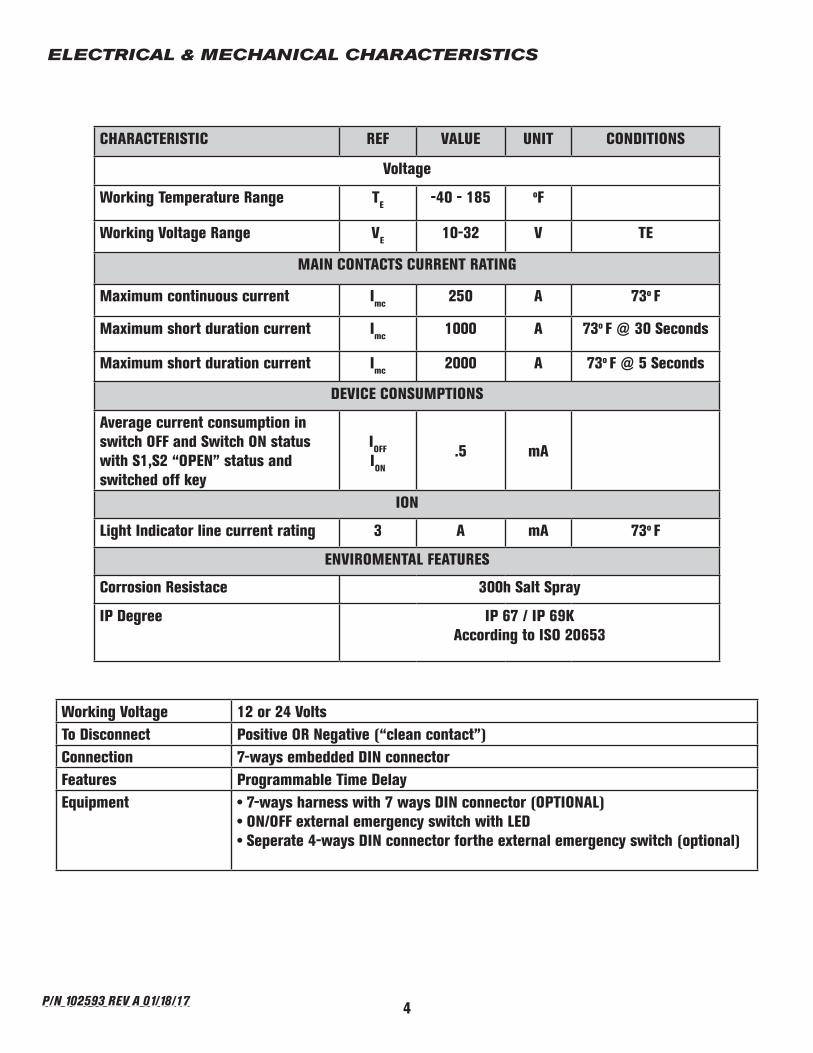
CHARACTERISTIC REF VALUE UNIT CONDITIONS
Voltage
Working Temperature Range TE -40 - 185 oF
Working Voltage Range VE 10-32 V TE
MAIN CONTACTS CURRENT RATING
Maximum continuous current Imc 250 A 73o F
Maximum short duration current Imc 1000 A 73o F @ 30 Seconds
Maximum short duration current Imc 2000 A 73o F @ 5 Seconds
DEVICE CONSUMPTIONS
Average current consumption in switch OFF and Switch ON status with S1,S2 “OPEN” status and switched off key
IOFF
ION
.5 mA
ION
Light Indicator line current rating 3 A mA 73o F
ENVIROMENTAL FEATURES
Corrosion Resistace 300h Salt Spray
IP Degree IP 67 / IP 69KAccording to ISO 20653
ELECTRICAL & MECHANICAL CHARACTERISTICS
Working Voltage 12 or 24 VoltsTo Disconnect Positive OR Negative (“clean contact”)Connection 7-ways embedded DIN connectorFeatures Programmable Time DelayEquipment • 7-ways harness with 7 ways DIN connector (OPTIONAL)
• ON/OFF external emergency switch with LED• Seperate 4-ways DIN connector forthe external emergency switch (optional)
P/N 102593 REV A 01/18/17

5
Watch Dog® Time Delay Programming
NOTE:• If an error occurs during the programming procedure, the de-
vice enters into normal operating mode and the S2 (Emergency Switch) light blinks for 10 seconds. - Disconnect pin 7 from the battery and the repeat steps 1-4.
• The Time Delay is set in the Watch Dog®memory and is present even after the switch is disconnected from a power supply.
• Every time the Watch Dog is powered on, the S2 light will blink to show the Time Delay.
Programming Instructions1. NOTE: The default value for the time delay is 6 minutes.2. To start the programming procedure, connect the Watch Dog® as illustrated in the wiring diagram. A. NOTE: The Switch S2 (External Emergency Switch) should be in the OFF position. The GREEN wire (Pos. Battery) should NOT be connected.3. Now connect the GREEN wire to the positive battery terminal.4. The light will blink a specified number of times depending on the current time delay setting (see time delay table above) memorized by the device. The green LED on Switch S2 will then turn on for 2.5 seconds. Within 3 seconds after the green LED turns off, toggle Switch S2 ON and then OFF.5. Wait for the green LED to blink the required number of times for the chosen time delay (see time delay table above). The light will blink slowly to give you enough time to select your preferred time delay. Once the green LED has blinked the desired number of times, toggle Switch S2 ON and then OFF.
LED Time-Delay Sequence
LED Blinks Time Delay
1 30 Seconds
2 1 Minute
3 3 Minutes
4 6 minutes
P/N 102593 REV A 01/18/17

6
Watch Dog® and Emergency Switch Mounting
P/N 102593 REV A 01/18/17

7
1. Using M4 bolts mount the Watch Dog®
to the chassis following these requirements:
A. Mount the Watch Dog®as close as possible to the battery - No more than 20” away B. At least 32” from the ground C. Mount the studs upward or to the side do not mount the switch with the studs facing the ground. D. Ensure the Watch Dog® is shielded from impact from debris.
Torque the mounting bolts to 53 (+/- 17) in lbs.
2. Using M6 bolts, mount the external emergency switch to the chassis as close as possible to the drivers door following these requirements:
A. Switch should be clearly visible and easily accessible. B. At least 32” from the ground C. Ensure the Emergency Switch is shielded from impact from debris. Torque the mounting bolts to 70 (+/- 17) in lbs.
5MENBER’S WATCH DOG TECHNICAL MANUAL - Electrical Battery Main Switch
2. Mechanical Fixation
84mm [3,31'']
60m
m [2,3
6''] 4 x 6.4mm [0,26'']
24mm [0,94'']
38mm [1,5'']
2 x 6.5mm [0,26'']
0 1 2 0(O N )
14 237 5
OFF 5015
1 2 3 4
+ -
8630 87
85
DL1
R
DL1
R
4 3 2 1
+ -
0 1 2 0(O N )
14 23 75
OFF 5015
DL1
R
DL1
R
4 3 2 1
1 2 3 4
Using 4 M6 bolts with a closing torque on nuts of 6±2 Nm [53,1±17,7 lbf*in] and referring to the “WatchDog fixing diagram”, fix the WatchDog to the chassis in a position:• as close as possible to the battery (the cable length between the WatchDog and the battery pole should be < 0,5m [20’’]);• at 0.8m [31,5’’] (at least) from the ground;• not exposed to gravel impacts;
The device can be installed in any orientation except with studs pointing to the ground; protections for studs are recommended (whether the WatchDog is installed inside or outside the battery box).
* External Emergency Switch (accessory) p.n. 00227000 ON/OFF external emercency switch with LED.Mechanical Fixation
• To the chassis, with 2 M6 bolts, in a position as close as possible to the driver door. It should be clearly visible and easily accessible• Height from the ground: > 0.8m [31,5’’]• In a position not exposed to gravel impacts• Closing torque on M6 nuts: 8±2 Nm [70,8±17,7 lbf*in]N.B.: If any other switch is used instead, it shall withstand min. 0,1A /12V and shall have IP67 / IP69K protection degrees
84mm [3,31'']
60m
m [2,3
6''] 4 x 6.4mm [0,26'']
24mm [0,94'']
38mm [1,5'']
2 x 6.5mm [0,26'']
0 1 2 0(O N )
14 237 5
OFF 5015
1 2 3 4
+ -
8630 87
85
DL1
R
DL1
R
4 3 2 1
+ -
0 1 2 0(O N )
14 23 75
OFF 5015
DL1
R
DL1
R
4 3 2 1
1 2 3 4
BATTERY SWITCH FIXING DIAGRAM
EXTERNAL SWITCH FIXING DIAGRAM*
3. ELECTRICAL CONNECTIONS
For the electrical connection of the WatchDog to the vehicle system, refer to the wiring diagrams in section 5.
• S1 (dashboard push button) is a push-button for the device activation and S2 (External Emergency Switch ) is a switch for the device emergency deactivation (with a LIGHT indicator with maximum absorbed current of 3A): both should have minimum contact rating of 5mA@12V (and @24V).• KEY is the vehicle ignition key, positive in “ON” position.
3.1 POWER CONNECTIONS• Power cables with total section of 90 mm2 [AWG 3/0] or more for each stud are recommended;• Maximum closing torque on M10 studs: 19 Nm [168,1 lbf*in].
NOTE7-ways wiring: 1x1,5 [AWG 15] + 6x1mm2 [AWG 17]4-ways wiring: 4x0,75mm2 [AWG 18]
In-cab pushbutton: any (ON)-OFF push button min. 0,1A / 12V
Installation layout - Example
S1 - PUSH BUTTON to switch ON
the WatchDog
S2 - EMERGENCY SWITCH(easily accessible, on driver side)
GREEN LED Light
7-WAYS HARNESSWatchDog (close to the battery)
IgnitionKey
Ref. 00712600
Watch Dog® and Emergency Switch Mounting (Continued)
P/N 102593 REV A 01/18/17

8
5MENBER’S WATCH DOG TECHNICAL MANUAL - Electrical Battery Main Switch
2. Mechanical Fixation
84mm [3,31'']
60m
m [2,3
6''] 4 x 6.4mm [0,26'']
24mm [0,94'']
38mm [1,5'']
2 x 6.5mm [0,26'']
0 1 2 0(O N )
14 237 5
OFF 5015
1 2 3 4
+ -
8630 87
85
DL1
R
DL1
R
4 3 2 1
+ -
0 1 2 0(O N )
14 23 75
OFF 5015
DL1
R
DL1
R
4 3 2 1
1 2 3 4
Using 4 M6 bolts with a closing torque on nuts of 6±2 Nm [53,1±17,7 lbf*in] and referring to the “WatchDog fixing diagram”, fix the WatchDog to the chassis in a position:• as close as possible to the battery (the cable length between the WatchDog and the battery pole should be < 0,5m [20’’]);• at 0.8m [31,5’’] (at least) from the ground;• not exposed to gravel impacts;
The device can be installed in any orientation except with studs pointing to the ground; protections for studs are recommended (whether the WatchDog is installed inside or outside the battery box).
* External Emergency Switch (accessory) p.n. 00227000 ON/OFF external emercency switch with LED.Mechanical Fixation
• To the chassis, with 2 M6 bolts, in a position as close as possible to the driver door. It should be clearly visible and easily accessible• Height from the ground: > 0.8m [31,5’’]• In a position not exposed to gravel impacts• Closing torque on M6 nuts: 8±2 Nm [70,8±17,7 lbf*in]N.B.: If any other switch is used instead, it shall withstand min. 0,1A /12V and shall have IP67 / IP69K protection degrees
84mm [3,31'']
60m
m [2,3
6''] 4 x 6.4mm [0,26'']
24mm [0,94'']
38mm [1,5'']
2 x 6.5mm [0,26'']
0 1 2 0(O N )
14 237 5
OFF 5015
1 2 3 4
+ -
8630 87
85
DL1
R
DL1
R
4 3 2 1
+ -
0 1 2 0(O N )
14 23 75
OFF 5015
DL1
R
DL1
R
4 3 2 1
1 2 3 4
BATTERY SWITCH FIXING DIAGRAM
EXTERNAL SWITCH FIXING DIAGRAM*
3. ELECTRICAL CONNECTIONS
For the electrical connection of the WatchDog to the vehicle system, refer to the wiring diagrams in section 5.
• S1 (dashboard push button) is a push-button for the device activation and S2 (External Emergency Switch ) is a switch for the device emergency deactivation (with a LIGHT indicator with maximum absorbed current of 3A): both should have minimum contact rating of 5mA@12V (and @24V).• KEY is the vehicle ignition key, positive in “ON” position.
3.1 POWER CONNECTIONS• Power cables with total section of 90 mm2 [AWG 3/0] or more for each stud are recommended;• Maximum closing torque on M10 studs: 19 Nm [168,1 lbf*in].
NOTE7-ways wiring: 1x1,5 [AWG 15] + 6x1mm2 [AWG 17]4-ways wiring: 4x0,75mm2 [AWG 18]
In-cab pushbutton: any (ON)-OFF push button min. 0,1A / 12V
Installation layout - Example
S1 - PUSH BUTTON to switch ON
the WatchDog
S2 - EMERGENCY SWITCH(easily accessible, on driver side)
GREEN LED Light
7-WAYS HARNESSWatchDog (close to the battery)
IgnitionKey
Ref. 00712600
Watch Dog Wiring
Watch Dog® Normal Operating Mode
7-Pin Wire Harness Pin-Out 4-Pin Wire Harness Pin-OutGray Push Button Command Black Neg. Battery TerminalBlack Neg. Battery Terminal Blue Emergency Switch CommandYellow Ignition Key Command Brown System Status - Controls External
Emergency Light LEDBlue Emergency Switch Command Red Pos. Battery TerminalBrown System Status - Controls External Emer-
gency Light LEDWhite Not ConnectedGreen Pos. Battery Terminal
System Activation
1. Switch S2 (External Emergency Switch) must be in the ON position.2. Push Switch S1 (Dash/Cabin Pushbutton).3. The Watch Dog® will enter ON status, and close the main contacts allowing current to flow from the battery to the vehicle. The green LED located on Switch S2 will turn ON.
NOTE: The ignition key does not need to be in the ON position to activate the Watch Dog®.
Time-Delayed Shutdown
1. With Switch S2 in the ON position, turn the ignition key to the OFF position. This will start the preprogrammed time delay and cause the LED on Switch S2 to blink.2. Once the time delay cycle is complete, the LED on Switch S2 will turn OFF and the main contacts on the Watch Dog® unit will open.3. If at any time the user wishes to abort the time delay sequence, simply turn the key back to the ON position, or push Switch S1. The time delay will stop and the system will remain in operation.
Emergency Shutdown
1. Flipping Switch S2 to the OFF position any time during operation will force the Watch Dog® into emergency deactivation. This will open the main contacts, turn off the LED on Switch S2 and aborts the time delay sequence if active.
P/N 102593 REV A 01/18/17

9P/N 102593 REV A 01/18/17

2 MENBER’S WATCH DOG TECHNICAL MANUAL - Electrical Battery Main Switch
11
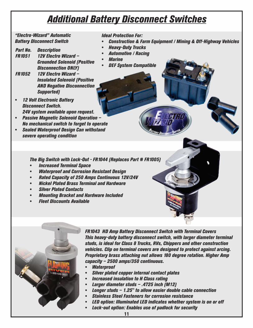
The Big Switch with Lock-Out - FR1044 (Replaces Part # FR1005)• Increased Terminal Space• Waterproof and Corrosion Resistant Design• Rated Capacity of 250 Amps Continuous 12V/24V• Nickel Plated Brass Terminal and Hardware • Silver Plated Contacts• Mounting Bracket and Hardware Included• Fleet Discounts Available
Ideal Protection For: • Construction & Farm Equipment / Mining & Off-Highway Vehicles• Heavy-Duty Trucks• Automotive / Racing• Marine• DEF System Compatible
“Electro-Wizard” Automatic Battery Disconnect Switch
• 12 Volt Electronic Battery Disconnect Switch. 24V system available upon request.• Passive Magnetic Solenoid Operation – No mechanical switch to forget to operate• Sealed Waterproof Design Can withstand severe operating condition
Part No. DescriptionFR1051 12V Electro Wizard – Grounded Solenoid (Positive Disconnection ONLY)FR1052 12V Electro Wizard – Insulated Solenoid (Positive AND Negative Disconnection Supported)
FR1043 HD Amp Battery Disconnect Switch with Terminal Covers This heavy-duty battery disconnect switch, with larger diameter terminal studs, is ideal for Class 8 Trucks, RVs, Chippers and other construction vehicles. Clip on terminal covers are designed to protect against arcing. Proprietary brass attaching nut allows 180 degree rotation. Higher Amp capacity – 2500 amps/350 continuous.• Waterproof• Silver plated copper internal contact plates• Increased insulation to H Class rating• Larger diameter studs – .4725 inch (M12)• Longer studs – 1.25" to allow easier double cable connection• Stainless Steel Fasteners for corrosion resistance• LED option: Illuminated LED indicates whether system is on or off• Lock-out option: Enables use of padlock for security
Additional Battery Disconnect Switches

Flaming River Industries, Inc.800 Poertner Dr. Berea, Ohio 44017
1-800-648-8022 • www.flamingriver.comP/N 102593 REV A 01/18/17