introduction closed loop stepping motor and · pdf filethe utilizes our unique closed loop...
TRANSCRIPT
Ste
pp
ing
Mo
tors
Intro
du
ctio
nA
SA
SC5-P
hase
Mic
roste
pRK
2-P
hase
Fu
ll/Half
UM
K
5-P
hase
Mic
roste
pCRK
2-P
hase
Mic
roste
pRBK
2-P
hase
Mic
roste
pCM
K2-P
hase
PK
/PV
2-P
has
ePK
EMP4
00
SG80
30
JA
ccesso
ries
Insta
llatio
n
AC
Inp
ut
DC
Inp
ut
AC
Inp
ut
DC
Inp
ut
Without E
ncoderW
ith E
nc
od
er
Co
ntro
llers
C-13
Page
AS Series ································································· C-14ASC Series ······························································ C-62
Stepping Motors
Closed Loop Stepping Motor and Driver
PackagesAC Input AS Series
DC Input ASC Series

Ste
pp
ing
Mo
tors
C-14 ORIENTAL MOTOR GENERAL CATALOG 2009/2010 Features C-14 / System Configuration C-20 / Product Line C-25
●Additional Information●Technical reference ➜ Page F-1
Safety standards ➜ Page G-2
The utilizes our unique closed loop control.
This is a motor and driver package product offering the
user-friendliness of a stepping motor combined with
improved response and reliability.
List of safety standard approved products (Model, Standards, File No., Certification Body) ●➜ Page G-11
Closed Loop Stepping Motor and Driver Package
AS Series
Features ■
Incorporating Our Unique Closed Loop Control ●This product uses our closed loop control to maintain positioning
operation even during abrupt load fluctuations and accelerations.
The rotor position detection sensor monitors the rotation. When an
overload condition is detected, it will instantaneously regain control
using the closed loop mode.
When an overload condition continues it will output an alarm signal,
thereby providing reliability equal to that of a servo motor.
is designed as a "package" consisting of a motor and a driver.
Sensor detects rotor position
◇ Control Diagram
Input Counter
Deviation Counter
Rotor Position
Counter Exc
itati
on S
equence
Contr
ol
Outp
ut
Ele
ment
Motor
Sensor
Input Pulse
Normal (Positioning deviation is less than ±1.8˚)
Motor runs in open loop mode like a stepping motor.
During Overload Condition (Positioning deviation is ±1.8° or more)
The closed loop mode is engaged to maintain the positioning operation.
◇ Angle – Torque Characteristics
-7.2˚ -5.4˚ -3.6˚ -1.8˚ 0 1.8˚ 3.6˚ 5.4˚ 7.2˚Position
Torq
ue
②Closed Loop Mode
②Closed Loop Mode
①Open Loop Mode
Stepping Motor
①If the positioning deviation is less than ±1.8˚, the motor
runs in open loop mode like a stepping motor.
②If the positioning deviation is ±1.8˚ or more, the motor runs
in closed loop mode and the position is corrected by
exciting the motor windings to generate maximum torque
based on the rotor position.
◇The Sensor to Detect Rotor's PositionThe rotor position detection sensor uses the change in
inductance caused by change in the distance between the stator
teeth and the teeth on the sensor rotor to detect rotor position.
FeaturesThis structure can be made small and thin, so the overall size of ●the motor can be reduced.
High resolution ●This structure does not use electronic parts, so it is not affected by ●heat or vibration.
-1
-0.5
0
0.5
1
1.25
0 60˚ 120˚ 180˚ 240˚ 300˚ 360˚
Sign
al L
evel
A-Phase B-Phase
Sensor Output Signal
Rotor Angle (Electrical Angle)
RoHS-Compliant

Ste
pp
ing
Mo
tors
Intro
du
ctio
nA
SA
SC5-P
hase
Mic
roste
pRK
2-P
hase
Fu
ll/Half
UM
K
5-P
hase
Mic
roste
pCRK
2-P
hase
Mic
roste
pRBK
2-P
hase
Mic
roste
pCM
K2-P
hase
PK
/PV
2-P
has
ePK
EMP4
00
SG80
30
JA
ccesso
ries
Insta
llatio
n
AC
Inp
ut
DC
Inp
ut
AC
Inp
ut
DC
Inp
ut
Without E
ncoderW
ith E
nc
od
er
Co
ntro
llers
C-15Specifications, Characteristics C-29 / Dimensions C-41 / Connection and Operation C-50 / Motor and Driver Combinations C-60
High Response ●Like conventional stepping motors,
operates in synchronism
with command pulses. This makes
possible short stroke positioning in
a short time.
Measurement Condition:
Feed 1/5 rotation
Load inertia 250×10−7 kg·m2 (J)
(1.365 oz-in2)
No Gain Tuning ●Gain tuning for servo motors is
critical, troublesome and time-
consuming. Since the
operates like a stepping motor, there
are no gain tuning requirements.
is ideal for low rigidity
applications, such as belt and pulley
system.
The ● Complies with Major Safety StandardsThe AS Series is recognized by the UL/CSA Standards and
conforms to EN Standards. [The products with the motor frame
size of 42 mm (1.65 in.) are recognized with the UL Standards and
conforms to EN Standards.] The CE Marking certifies compliance
with the EMC and Low Voltage Directives.
No Hunting ●Since is a stepping motor, it has no hunting problem.
Therefore, when it stops, its position is completely stable and does
not fluctuate. is ideal for applications in which hunting
would be a problem.
Servo Motor
Hunting Complete Stop
●Low Vibration at Low SpeedThe driver employs advanced technology that produces smoothness
comparable to a microstep driver. Its vibration level is incredibly
low, even when operating in the low speed range. When frequent
changes from low to high (or vice versa) speed operations are
required, the use of the Resolution Select Function solves the
problem. provides resolution as high as 0.036˚ per step
without any damping mechanism or other mechanical device.
Low Speed
High Speed
CCD Camera
is well-suited to applications where smooth movement or stability is required, such as where a camera is used to monitor the quality of a product.
Motor/Driver Connection with a Single Cable ● requires only one cable for connection between the motor
and the driver. Wiring is much simpler compared with conventional
servo motors requiring two cables, one for motor and the other for
encoder. The cable can be extended to a maximum of 20 m (65.6 ft.)
[10 m (32.8 ft.) for flexible extension cable], so the motor and the
driver can be installed in locations far apart.
A Full Lineup including Geared Types and Industrial ●Connector Type
The geared types enable driving of large inertial loads and
positioning at higher accuracy, while the industrial connector type
provides IP65 of ingress protection against dust and water.
The offers a wide range of models meeting the needs of
various applications.
Improved Motor ●• Protective Earth Terminal
[Excluding motors with a frame size of 42 mm (1.65 in.)]
• Twice the Motor Life (compared with a conventional model)
The life of a motor is affected by its bearing.
The achieves approximately twice the life of a conventional
motor by adopting a modified bearing. [Available only with the
standard type and standard electromagnetic brake type with a frame
size of 60 or 85 mm (2.36 or 3.35 in.).]
● RoHS-CompliantThe conforms to the RoHS Directive that prohibits the use
of six chemical substances including lead and cadmium.
Details of RoHS Directive ● ➜ Page G-38
Motor Movement
Pulse Input
Positioning Completion Signal
Standard Type Industrial Connector
A dedicated motor cable for industrial connector type (sold ●separately) is needed to connect the industrial connector type motor and driver.
Protective Earth Terminal

Ste
pp
ing
Mo
tors
C-16 ORIENTAL MOTOR GENERAL CATALOG 2009/2010 Features C-14 / System Configuration C-20 / Product Line C-25
A Full Lineup of
Characteristics Comparison for Motors and Geared Motors ■
PermissibleTorque
Maximum Holding Torque
MaximumTorque
PermissibleTorque
MaximumTorque
4000
500
600
70
37 (320) 3
0.012
0.36
45
0.0072
0.0036 037 (320)
60 (530)
55 (480)
12 (106)
4 (35)
Maximum Holding Torque40000.364 (35)
No
n-b
ack
lash
Lo
w b
ack
lash
Standard
Standard Type IndustrialConnector
TH Geared(Parallel shaft)
PN Geared(Planetary)
Harmonic Geared(Harmonic drive)
· A wide variety of low gear ratios, high-speed operation
· Gear ratios: 3.6:1, 7.2:1, 10:1, 20:1, 30:1
· The industrial connector type motor offering IP65 of
ingress protection against dust and water.
· High speed (low gear ratios), high accuracy positioning
· High permissible/maximum torque
· A wide variety of gear ratios for selecting the
desired step angle (resolution)
· Centered output shaft
· Gear ratios: 5:1, 7.2:1, 10:1, 25:1, 36:1, 50:1
· High accuracy positioning
· High permissible/maximum torque
· High gear ratios, high resolution
· Centered output shaft
· Gear ratios: 50:1, 100:1
· Basic model of motor
Permissible Torque/
Maximum Torque [N·m (lb-in)]
Motor Type
Geared TypeFeatures
Output Shaft Speed
[r/min]
Backlash
[min]
Basic Resolution
[deg/step]
You are sure to find a unit that perfectly matches the needs of your specific application.
Standard Type Standard Type Industrial Connector✽
TH Geared Type
PN Geared Type
Harmonic Geared Type
AC Power-Supply Built-In Controller
AC Power-SupplyPulse Input
DC Power-SupplyPulse Input
Select an optimal motor
based on the required
torque, resolution, etc.
Select an optimal
driver based
on the system
requirement.
Each "package" consists
of a motor and a driver.
Note:
The values shown above must be used as reference. These values vary depending on the frame size and gear ratio. ●
Motors equipped with an electromagnetic brake are also available.✽
(An electromagnetic brake is not available on certain types.)
A dedicated cable (sold separately) is needed to connect the motor ✽
and driver.

Ste
pp
ing
Mo
tors
Intro
du
ctio
nA
SA
SC5-P
hase
Mic
roste
pRK
2-P
hase
Fu
ll/Half
UM
K
5-P
hase
Mic
roste
pCRK
2-P
hase
Mic
roste
pRBK
2-P
hase
Mic
roste
pCM
K2-P
hase
PK
/PV
2-P
has
ePK
EMP4
00
SG80
30
JA
ccesso
ries
Insta
llatio
n
AC
Inp
ut
DC
Inp
ut
AC
Inp
ut
DC
Inp
ut
Without E
ncoderW
ith E
nc
od
er
Co
ntro
llers
C-17Specifications, Characteristics C-29 / Dimensions C-41 / Connection and Operation C-50 / Motor and Driver Combinations C-60
Pulse Input
Various motor controls can be performed using a
pulse generator provided by the user.
Built-In Controller
The built-in pulse generation function allows
the motor to be driven via a directly connected
programmable controller or personal computer.
Since no separate pulse generator is required, the
drivers of this type save space, simplify wiring, and
also allow the number of axes to be increased with
ease.
Each series offers various motor frame sizes in accordance with the motor type and power supply voltage, as shown below. ●[□42 (□1.65): indicates a motor frame size of 42 mm (1.65 in.).]
Power Supply Voltage Standard TypeStandard Type
Industrial ConnectorTH Geared Type PN Geared Type
Harmonic GearedType
AC Power SupplyAS Series
Single-Phase 100-115 VAC□42 (□1.65)□60 (□2.36)□85 (□3.35)
□60 (□2.36)□85 (□3.35)
□42 (□1.65)□60 (□2.36)□90 (□3.54)
□42 (□1.65)□60 (□2.36)□90 (□3.54)
□42 (□1.65)□60 (□2.36)□90 (□3.54)
Pulse InputPackage
Single-Phase 200-230 VAC□60 (□2.36)□85 (□3.35)
□60 (□2.36)□85 (□3.35)
□60 (□2.36)□90 (□3.54)
□60 (□2.36)□90 (□3.54)
□60 (□2.36)□90 (□3.54)
Built-InControllerPackage Three-Phase 200-230 VAC
□60 (□2.36)□85 (□3.35)
□60 (□2.36)□85 (□3.35)
□60 (□2.36)□90 (□3.54)
□60 (□2.36)□90 (□3.54)
□60 (□2.36)□90 (□3.54)
DC Power SupplyASC SeriesPulse Input Package
24 VDC□28 (□1.10)□42 (□1.65)□60 (□2.36)
–□28 (□1.10)□42 (□1.65)□60 (□2.36)
□28 (□1.10)□42 (□1.65)□60 (□2.36)
□28 (□1.10)□42 (□1.65)□60 (□2.36)
● : A pulse input package and a built-in controller package are available. White background: A pulse input package is available. All the packages can be available with a motor and an electromagnetic brake. [Except for the industrial connector type and ● ASC Series with a motor frame size of 28 mm (1.10 in.).]
Two Types of Drivers ■
Programmable Controller
AC Power Supply DC Power Supply
Programmable Controller
orPersonal Computer
Pulse Generator
Motor
Driver
Motor
Driver

Ste
pp
ing
Mo
tors
C-18 ORIENTAL MOTOR GENERAL CATALOG 2009/2010 Features C-14 / System Configuration C-20 / Product Line C-25
Features of the Built-In Controller Package ■
The built-in controller driver has an integrated controller which ensures a simple, efficient solution
for stepping motor applications.
Intelligent, integrated, and ideal for technology's increasing demand on motion control, the built-in
controller is computer-programmable via an RS-232C connection.
Positioning
Continuous
Mechanical Home
Alarm Outputfrom Driver
Electrical Home
ALARM OUT
●Operating Modes
●Alarm Functions
●Daisy Chain
●Linked Motion Capability
●Speed Change on the Fly
Time
No. 2
Single Motion Linked Motion
PC
The running speed of the motor can be changed while
the motor is in motion.
Up to 36 units can be daisy chained via a customer supplied cable.
When a START signal is received motions 0, 1 and 2 are executed without stopping between each one.
The driver can notify the host controller which alarm has occurred.
The driver can flash LEDs to indicate which alarm has occurred.
Motor
Driver
PLC
No. 0 No. 1 No. 2
5000 Hz
2000 Hz
1000 Hz
Sp
ee
d
OperatingModes
4
PC
or

Ste
pp
ing
Mo
tors
Intro
du
ctio
nA
SA
SC5-P
hase
Mic
roste
pRK
2-P
hase
Fu
ll/Half
UM
K
5-P
hase
Mic
roste
pCRK
2-P
hase
Mic
roste
pRBK
2-P
hase
Mic
roste
pCM
K2-P
hase
PK
/PV
2-P
has
ePK
EMP4
00
SG80
30
JA
ccesso
ries
Insta
llatio
n
AC
Inp
ut
DC
Inp
ut
AC
Inp
ut
DC
Inp
ut
Without E
ncoderW
ith E
nc
od
er
Co
ntro
llers
C-19Specifications, Characteristics C-29 / Dimensions C-41 / Connection and Operation C-50 / Motor and Driver Combinations C-60
Position Control ●Incremental mode (relative distance specification)/Absolute mode (absolute position specification) ●Linked operation (a maximum of four motion profiles may be linked) ●Data range (in pulses): ● −8 388 608 to +8 388 607
Operating speed: 10 Hz to 500 kHz (set in 1 Hz increments) ●
Four Operation Modes ●1. Positioning
2. Mechanical return to home (+LS, −LS, HOMELS)
3. Continuous
4. Electrical return to home
General Inputs/Outputs ●8 programmable inputs ●8 programmable outputs ●
Daisy Chain Capability ●Up to 36 units can be daisy chained with unique device ID's. ●
Communication ●ASCII based commands ●Conforms to RS-232C communication specifications ●Start-stop asynchronous transmission method ●Transmission speed: 9600 bps ●Data length: 8 bits, 1 stop bit, no parity ●Protocol: TTY (CR+LF)
Modular 4-pin connector ●
Program Memory ●Maximum number of programs: 14 (including STARTUP) ●Maximum lines per program: 64 ●Commands per line: 1 ●Program variables: 26 (A to Z) ●
Built-In Functions ●
Using Windows HyperTerminal®,
programming the built-in
controller driver is a simple task.
ALPHA STEP PLUS DRIVER
>EDIT PROGRAM1
Program Name : PROGRAM1
( 1) VR=20000
( 2) DIS=1200
( 3) MI
( 4) CALL WAITEND
( 5) OUT1=1
( 6) MGHP
( 7) END
>> COMMAND : _
Example: "PROGRAM1"
PROGRAM1 Defi nitionOperating speed: 20000 Hz ●Move distance: 1200 pulses ●Call a subroutine that waits for the motor ●to stop before moving on to the next
command
Turn on output #1 ●Seek the mechanical home position in ●the positive direction
End of program ●
Selectable motor-resolution ●Run and stop current values ●Velocity filter set value ●Motor rotation direction ●External stop ●
Display values ●Incremental moves ●I/O status ●
Sensor logic ●Overtravel limits ●Software overtravel ●Alarm history ●Syntax checking ●

Ste
pp
ing
Mo
tors
C-20 ORIENTAL MOTOR GENERAL CATALOG 2009/2010 Features C-14 / System Configuration C-20 / Product Line C-25
System Configuration ■
Pulse Input Package Standard Type ●An example of a single-axis system configuration with the EMP400 Series controller.
AS Series
Accessories and Peripheral Equipment (Sold separately)
Controller (Sold separately)
(Sold separately)
①Controller(➜ Page C-269)
Motor Driver
AC Power Supply(Main power supply)
②MotorMountingBrackets(➜ Page C-312)
⑥Driver CablesGeneral-PurposeType(➜ Page C-300)
⑧Driver CablesEMP SeriesDedicated Type(➜ Page C-300)
⑨Connector – TerminalBlock ConversionUnit(➜ Page C-318)
⑦Connector – TerminalBlock ConversionUnit(➜ Page C-301)
③FlexibleCouplings(➜ Page C-302)
⑤DIN RailMountingPlate(➜ Page C-317)
Driver Cable EMP Series
Dedicated Type [1 m (3.3 ft.)]
CC01EMP4EMP401-1
Connecter – Terminal Block
Conversion Unit [1 m (3.3 ft.)]
CC50T1
DIN Rail
Mounting Plate
PADP01
Flexible
Coupling
MCS300808
Motor
Mounting Bracket
PAL2P-5A
ControllerExtension Cable
[3 m (9.8 ft.)]
CC03AIP
ProgrammableController
(Not supplied)
(Not supplied)
24 VDC PowerSupply
(Not supplied)
AS66AAE
●Example of System Configuration
AS Series
No. Product Name Overview Page
②
③
⑤
⑥
⑦
⑧
C-269C-312C-302
C-297
C-317C-300C-301C-300C-318
① ControllerMotor Mounting BracketsFlexible CouplingsExtension CablesFlexible Extension CablesDIN Rail Mounting PlateDriver Cables General-Purpose TypeConnector – Terminal Block Conversion UnitDriver Cables EMP Series Dedicated TypeConnector – Terminal Block Conversion Unit
This controller outputs pulse commands that determine the rotation amount and rotating speed.Dedicated mounting bracket for the motor.Coupling that connects the motor shaft to the driven shaft.Cable for extending the wiring distance between the motor and driver [1 to 20 m (3.3 to 65.6 ft.)].Cable offering flexibility, used to extend the wiring distance between the motor and driver [1 to 10 m (3.3 to 32.8 ft.)].Use this plate (PADP01) when installing the driver to a DIN rail.General-purpose cable for connecting the driver and controller [1 m, 2 m (3.3 ft., 6.6 ft.)].Set of terminal block and cable (CC36T1) for connecting the driver and controller [1 m (3.3 ft.)].Dedicated cable with connector for connecting the driver and EMP Series controller [1 m, 2 m (3.3 ft., 6.6 ft.)].Set of terminal block and cable (CC50T1) for connecting the EMP Series controller and host controller [1 m (3.3 ft.)].⑨
④ExtensionCables(➜ Page C-297)
④
The system configuration shown above is an example. Other combinations are available. ●

Ste
pp
ing
Mo
tors
Intro
du
ctio
nA
SA
SC5-P
hase
Mic
roste
pRK
2-P
hase
Fu
ll/Half
UM
K
5-P
hase
Mic
roste
pCRK
2-P
hase
Mic
roste
pRBK
2-P
hase
Mic
roste
pCM
K2-P
hase
PK
/PV
2-P
ha
se
PK
EMP40
0SG
803
0J
Accesso
ries
Insta
llatio
n
AC
Inp
ut
DC
Inp
ut
AC
Inp
ut
DC
Inp
ut
Without E
ncoderW
ith E
nc
od
er
Co
ntro
llers
C-21Specifications, Characteristics C-29 / Dimensions C-41 / Connection and Operation C-50 / Motor and Driver Combinations C-60
System Configuration ■
Pulse Input Package Standard Type with Electromagnetic Brake ●An example of a single-axis system configuration with the EMP400 Series controller.
AS Series
Required Products (Sold separately) Controller (Sold separately)
Accessories and Peripheral Equipment (Sold separately)
(Sold separately)
①Extension Cables for Electromagnetic Brake Motor✽
(➜ Page C-297)
②Controller(➜ Page C-269)
Motor with Electromagnetic Brake Driver
CC01EMP4EMP401-1 CC50T1
DIN Rail
Mounting Plate
PADP01
Flexible Coupling
MCS300808
Motor
Mounting Bracket
PAL2P-5A
ControllerExtension Cable for
Electromagnetic Brake
Motor [3 m (9.8 ft.)]
CC03AIPM
(Not supplied)
24 VDC Power Supply forElectromagnetic Brake
(Not supplied)
24 VDC PowerSupply
(Not supplied)
AS66MAE
●Example of System Configuration(Sold separately)
AS Series
C-297
C-269C-312C-302C-317C-300C-301C-300C-318
①
②
③
④
⑤
⑥
⑦
⑧
⑨
Extension Cables for Electromagnetic Brake MotorFlexible Extension Cables for Electromagnetic Brake MotorControllerMotor Mounting BracketsFlexible CouplingsDIN Rail Mounting PlateDriver Cables General-Purpose TypeConnector – Terminal Block Conversion UnitDriver Cables EMP Series Dedicated TypeConnector – Terminal Block Conversion Unit
Dedicated cable for connecting the electromagnetic brake motor and driver [1 to 20 m (3.3 to 65.6 ft.)]. Be sure to purchase this cable.Dedicated cable offering flexibility, used to connect the electromagnetic brake motor and driver [1 to 10 m (3.3 to 32.8 ft.)]. Be sure to purchase this cable.This controller outputs pulse commands that determine the rotation amount and rotating speed.Dedicated mounting bracket for the motor.Coupling that connects the motor shaft to the driven shaft.Use this plate (PADP01) when installing the driver to a DIN rail.General-purpose cable for connecting the driver and controller [1 m, 2 m (3.3 ft., 6.6 ft.)].Set of terminal block and cable (CC36T1) for connecting the driver and controller [1 m (3.3 ft.)].Dedicated cable with connector for connecting the driver and EMP Series controller [1 m, 2 m (3.3 ft., 6.6 ft.)].Set of terminal block and cable (CC50T1) for connecting the EMP Series controller and host controller [1 m (3.3 ft.)].
(Not supplied)
✽When extending the wiring distance of electromagnetic brake type with frame size □42 mm (□1.65 in.), use a standard extension cable. (➜ Page C-297)
③Motor MountingBrackets(➜ Page C-312)
⑥Driver CablesGeneral-PurposeType(➜ Page C-300)
⑧Driver CablesEMP SeriesDedicated Type(➜ Page C-300)
⑨Connector – TerminalBlock ConversionUnit(➜ Page C-318)
⑦Connector – TerminalBlock ConversionUnit(➜ Page C-301)
④FlexibleCouplings(➜ Page C-302)
⑤DIN RailMounting Plate(➜ Page C-317)
No. Product Name Overview Page
ProgrammableController
AC Power Supply(Main power supply)
Connecter – Terminal Block
Conversion Unit
[1 m (3.3 ft.)]
Driver Cable EMP Series
Dedicated Type
[1 m (3.3 ft.)]
The system configuration shown above is an example. Other combinations are available. ●

Ste
pp
ing
Mo
tors
C-22 ORIENTAL MOTOR GENERAL CATALOG 2009/2010 Features C-14 / System Configuration C-20 / Product Line C-25
System Configuration ■
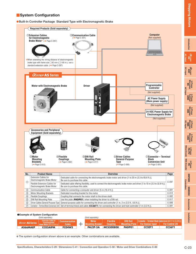
Built-In Controller Package Standard Type ●
AS Series
Accessories and Peripheral Equipment (Sold separately)
②Motor Mounting Brackets (➜ Page C-312)
⑥Driver Cables General-Purpose Type (➜ Page C-300)
⑦Connector – Terminal Block Conversion Unit (➜ Page C-301)
③Flexible Couplings (➜ Page C-302)
⑤DIN Rail Mounting Plate (➜ Page C-317)
④Extension Cables (➜ Page C-297)
Computer(Not supplied)
(Sold separately)(Sold separately)
For Sensor Input
CC20T1For Control I/0
CC36T1
DIN Rail
Mounting Plate
PADP01
Flexible
Coupling
MCS300808
Extension Cable
[3 m (9.8 ft.)]
CC03AIP
Motor
Mounting Bracket
PAL2P-5AAS66AAEP
●Example of System Configuration
AS SeriesConnector -- Terminal Block Conversion Unit [1 m (3.3 ft.)]
No. Product Name Overview Page
C-301
C-302
C-300C-317
C-297
C-301
①
③
C-312②
④
⑤
⑥
⑦
Communication Cable
Flexible CouplingsExtension CablesFlexible Extension CablesDIN Rail Mounting PlateDriver Cables General-Purpose TypeConnector – Terminal Block Conversion Unit
Cable for connecting a computer and driver [5 m (16.4 ft.)].
Coupling that connects the motor shaft to the driven shaft.Cable for extending the wiring distance between the motor and driver [1 to 20 m (3.3 to 65.6 ft.)].Cable offering flexibility, used to extend the wiring distance between the motor and driver [1 to 10 m (3.3 to 32.8 ft.)].Use this plate (PADP01) when installing the driver to a DIN rail.General-purpose cable for connecting the driver and controller [1 m, 2 m (3.3 ft., 6.6 ft.)].Set of terminal block and cable (CC36T1) for connecting the driver and host controller [1 m (3.3 ft.)].
Motor Mounting Brackets Dedicated mounting bracket for the motor.
FC04W5
Communication
Cable
Required Products (Sold separately)
①Communication Cable (➜ Page C-301)
(Not supplied)
Programmable Controller
(Not supplied)
Motor Driver
AC Power Supply(Main power supply)
The system configuration shown above is an example. Other combinations are available. ●
Ste
pp
ing
Mo
tors
Intro
du
ctio
nA
SA
SC5-P
hase
Mic
roste
pRK
2-P
hase
Fu
ll/Half
UM
K
5-P
hase
Mic
roste
pCRK
2-P
hase
Mic
roste
pRBK
2-P
hase
Mic
roste
pCM
K2-P
hase
PK
/PV
2-P
ha
se
PK
EMP40
0SG
803
0J
Accesso
ries
Insta
llatio
n
AC
Inp
ut
DC
Inp
ut
AC
Inp
ut
DC
Inp
ut
Without E
ncoderW
ith E
nc
od
er
Co
ntro
llers
C-23Specifications, Characteristics C-29 / Dimensions C-41 / Connection and Operation C-50 / Motor and Driver Combinations C-60
System Configuration ■
Built-In Controller Package Standard Type with Electromagnetic Brake ●
③Motor Mounting Brackets (➜ Page C-312)
⑥Driver Cables General-Purpose Type (➜ Page C-300)
⑦Connector – Terminal Block Conversion Unit (➜ Page C-301)
④Flexible Couplings (➜ Page C-302)
⑤DIN Rail Mounting Plate (➜ Page C-317)
(Sold separately)(Sold separately)
For Sensor Input
CC20T1FC04W5For Control I/0
CC36T1
DIN Rail
Mounting Plate
PADP01
Flexible
Coupling
MCS300808
Motor
Mounting Bracket
PAL2P-5A
Extension Cable forElectromagnetic
Brake Motor [3 m (9.8 ft.)]
CC03AIPMAS66MAEP
●Example of System Configuration
AS SeriesCommunication
Cable
No. Product Name Overview Page
C-297
C-301C-312C-302C-317C-300C-301
①
②
③
④
⑤
⑥
⑦
Extension Cables for Electromagnetic Brake Motor
Communication CableMotor Mounting BracketsFlexible CouplingsDIN Rail Mounting PlateDriver Cables General-Purpose TypeConnector – Terminal Block Conversion Unit
Dedicated cable for connecting the electromagnetic brake motor and driver [1 to 20 m (3.3 to 65.6 ft.)].Be sure to purchase this cable.
Cable for connecting a computer and driver [5 m (16.4 ft.)].Dedicated mounting bracket for the motor.Coupling that connects the motor shaft to the driven shaft.Use this plate (PADP01) when installing the driver to a DIN rail.General-purpose cable for connecting the driver and controller [1 m, 2 m (3.3 ft., 6.6 ft.)].Set of terminal block and cable (CC36T1) for connecting the driver and host controller [1 m (3.3 ft.)].
Flexible Extension Cables for Electromagnetic Brake Motor
Dedicated cable offering flexibility, used to connect the electromagnetic brake motor and driver [1 to 10 m (3.3 to 32.8 ft.)]. Be sure to purchase this cable.
Required Products (Sold separately)
①Extension Cables for ElectromagneticBrake Motor✽ (➜ Page C-297)
②Communication Cable (➜ Page C-301)
Computer(Not supplied)
(Not supplied)
Programmable Controller
(Not supplied)
AC Power Supply (Main power supply)
24 VDC Power Supply forElectromagnetic Brake
(Not supplied)
Motor with Electromagnetic Brake Driver
Accessories and Peripheral Equipment (Sold separately)
Connector -- Terminal Block Conversion Unit [1 m (3.3 ft.)]
AS Series
✽When extending the wiring distance of electromagnetic brake type with frame size □42 mm (□1.65 in.), use a standard extension cable. (➜ Page C-297)
The system configuration shown above is an example. Other combinations are available. ●

Ste
pp
ing
Mo
tors
C-24 ORIENTAL MOTOR GENERAL CATALOG 2009/2010 Features C-14 / System Configuration C-20 / Product Line C-25
Product Number Code ■
Standard Type ●
AS 6 6 A A E P① ② ③ ④ ⑤ ⑥ ⑦
① Series AS: AS Series② Motor Frame Size 4: 42 mm (1.65 in.) 6: 60 mm (2.36 in.) 9: 85 mm (3.35 in.)③ Motor Case Length④ Motor Type A: Standard (Single shaft) M: Electromagnetic Brake Type
⑤Power Supply Voltage A: Single-Phase 100-115 VAC C: Single-Phase 200-230 VAC
S: Three-Phase 200-230 VAC
⑥ Motor Classification
⑦Driver Type P: Built-In Controller Package
Blank: Pulse Input Package
Standard Type Industrial Connector ●
AS 6 6 A A T P① ② ③ ④ ⑤ ⑥ ⑦
Geared Type ●
AS 6 6 A C E P - N 50① ② ③ ④ ⑤ ⑥ ⑦ ⑧ ⑨
AS 4 6 A A P 2 - H 100① ② ③ ④ ⑤ ⑦ ⑩ ⑧ ⑨
① Series AS: AS Series② Motor Frame Size 6: 60 mm (2.36 in.) 9: 85 mm (3.35 in.)③ Motor Case Length④ Motor Shaft Type A: Single Shaft
⑤Power Supply Voltage A: Single-Phase 100-115 VAC C: Single-Phase 200-230 VAC
S: Three-Phase 200-230 VAC
⑥ Motor Classification
⑦Driver Type P: Built-In Controller Package
Blank: Pulse Input Package
① Series AS: AS Series② Motor Frame Size 4: 42 mm (1.65 in.) 6: 60 mm (2.36 in.) 9: 90 mm (3.54 in.)③ Motor Case Length④ Motor Type A: Standard (Single shaft) M: Electromagnetic Brake Type
⑤Power Supply Voltage A: Single-Phase 100-115 VAC C: Single-Phase 200-230 VAC
S: Three-Phase 200-230 VAC
⑥ Motor Classification
⑦Driver Type P: Built-In Controller Package
Blank: Pulse Input Package
⑧Gearhead Type T: TH Geared Type N: PN Geared Type
H: Harmonic Geared Type
⑨ Gear Ratio⑩ Reference Number

Ste
pp
ing
Mo
tors
Intro
du
ctio
nA
SA
SC5-P
hase
Mic
roste
pRK
2-P
hase
Fu
ll/Half
UM
K
5-P
hase
Mic
roste
pCRK
2-P
hase
Mic
roste
pRBK
2-P
hase
Mic
roste
pCM
K2-P
hase
PK
/PV
2-P
ha
se
PK
EMP40
0SG
803
0J
Accesso
ries
Insta
llatio
n
AC
Inp
ut
DC
Inp
ut
AC
Inp
ut
DC
Inp
ut
Without E
ncoderW
ith E
nc
od
er
Co
ntro
llers
C-25Specifications, Characteristics C-29 / Dimensions C-41 / Connection and Operation C-50 / Motor and Driver Combinations C-60
Product Line ■
The product names below are all for single shaft types, but there are
also double shaft types available for all products except for those
with electromagnetic brakes or industrial connector. Please contact
the nearest Oriental Motor sales office for further information on the
double shaft types.
Pulse Input Package ●Standard Type ◇
Power Supply Voltage Model (Single shaft)
Single-Phase 100-115 VAC
AS46AAAS66AAEAS69AAEAS98AAEAS911AAE
Single-Phase 200-230 VAC
AS66ACEAS69ACEAS98ACEAS911ACE
Three-Phase 200-230 VAC
AS66ASEAS69ASEAS98ASEAS911ASE
Standard Type Industrial Connector ◇Always use the motor cable for industrial connector type (sold
separately) for connection between the industrial connector type motor
and the driver.
Power Supply Voltage Model (Single shaft)
Single-Phase 100-115 VAC
AS66AATAS69AATAS98AATAS911AAT
Single-Phase 200-230 VAC
AS66ACTAS69ACTAS98ACTAS911ACT
Three-Phase 200-230 VAC
AS66ASTAS69ASTAS98ASTAS911AST
Motor cables for industrial connector type motor ➜ Page C-298
TH ◇ Geared TypePower Supply Voltage Model (Single shaft)
Single-Phase 100-115 VAC
AS46AA-T3.6 AS46AA-T7.2 AS46AA-T10 AS46AA-T20 AS46AA-T30 AS66AAE-T3.6AS66AAE-T7.2AS66AAE-T10AS66AAE-T20AS66AAE-T30AS98AAE-T3.6AS98AAE-T7.2AS98AAE-T10AS98AAE-T20AS98AAE-T30
Single-Phase 200-230 VAC
AS66ACE-T3.6AS66ACE-T7.2AS66ACE-T10AS66ACE-T20AS66ACE-T30AS98ACE-T3.6AS98ACE-T7.2AS98ACE-T10AS98ACE-T20AS98ACE-T30
Three-Phase 200-230 VAC
AS66ASE-T3.6AS66ASE-T7.2AS66ASE-T10AS66ASE-T20AS66ASE-T30AS98ASE-T3.6AS98ASE-T7.2AS98ASE-T10AS98ASE-T20AS98ASE-T30
Motor, Parallel Key✽1, Surge Suppressor✽2, Driver, Connector for Input/Output Signal, Mounting Bracket for Driver (with screws), Operating Manual
1 ✽ Only for the products with a key slot on the output shaft2 ✽ Only for electromagnetic brake type
The following items are included in each product.
Standard Type with Electromagnetic Brake ◇Electromagnetic brake models except frame size □42 mm (□1.65 in.)
must use an extension or flexible extension cable for an
electromagnetic brake motor.
Power Supply Voltage Model (Single shaft)
Single-Phase 100-115 VAC
AS46MAAS66MAEAS69MAEAS98MAE
Single-Phase 200-230 VAC AS66MCEAS69MCEAS98MCE
Three-Phase 200-230 VAC AS66MSEAS69MSEAS98MSE
Extension cables for electromagnetic brake motor ➜ Page C-297
TH ◇ Geared Type with Electromagnetic BrakePower Supply Voltage Model (Single shaft)
Single-Phase 100-115 VAC
AS46MA-T3.6AS46MA-T7.2AS46MA-T10AS46MA-T20AS46MA-T30AS66MAE-T3.6AS66MAE-T7.2AS66MAE-T10AS66MAE-T20AS66MAE-T30AS98MAE-T3.6AS98MAE-T7.2AS98MAE-T10AS98MAE-T20AS98MAE-T30
Single-Phase 200-230 VAC
AS66MCE-T3.6AS66MCE-T7.2AS66MCE-T10AS66MCE-T20AS66MCE-T30AS98MCE-T3.6AS98MCE-T7.2AS98MCE-T10AS98MCE-T20AS98MCE-T30
Three-Phase 200-230 VAC
AS66MSE-T3.6AS66MSE-T7.2AS66MSE-T10AS66MSE-T20AS66MSE-T30AS98MSE-T3.6AS98MSE-T7.2AS98MSE-T10AS98MSE-T20AS98MSE-T30
Extension cables for electromagnetic brake motor ➜ Page C-297

Ste
pp
ing
Mo
tors
C-26 ORIENTAL MOTOR GENERAL CATALOG 2009/2010 Features C-14 / System Configuration C-20 / Product Line C-25
PN ◇ Geared Type Power Supply Voltage Model (Single shaft)
Single-Phase 100-115 VAC
AS46AA-N7.2AS46AA-N10AS66AAE-N5AS66AAE-N7.2AS66AAE-N10AS66AAE-N25AS66AAE-N36AS66AAE-N50AS98AAE-N5AS98AAE-N7.2AS98AAE-N10AS98AAE-N25AS98AAE-N36AS98AAE-N50
Single-Phase 200-230 VAC
AS66ACE-N5AS66ACE-N7.2AS66ACE-N10AS66ACE-N25AS66ACE-N36AS66ACE-N50AS98ACE-N5AS98ACE-N7.2AS98ACE-N10AS98ACE-N25AS98ACE-N36AS98ACE-N50
Three-Phase 200-230 VAC
AS66ASE-N5AS66ASE-N7.2AS66ASE-N10AS66ASE-N25AS66ASE-N36AS66ASE-N50AS98ASE-N5AS98ASE-N7.2AS98ASE-N10AS98ASE-N25AS98ASE-N36AS98ASE-N50
Harmonic Geared Type ◇ Power Supply Voltage Model (Single shaft)
Single-Phase 100-115 VAC
AS46AA2-H50AS46AA2-H100AS66AAE-H50AS66AAE-H100AS98AAE-H50AS98AAE-H100
Single-Phase 200-230 VAC
AS66ACE-H50AS66ACE-H100AS98ACE-H50AS98ACE-H100
Three-Phase 200-230 VAC
AS66ASE-H50AS66ASE-H100AS98ASE-H50AS98ASE-H100
PN ◇ Geared Type with Electromagnetic BrakePower Supply Voltage Model (Single shaft)
Single-Phase 100-115 VAC
AS46MA-N7.2AS46MA-N10AS66MAE-N5AS66MAE-N7.2AS66MAE-N10AS66MAE-N25AS66MAE-N36AS66MAE-N50AS98MAE-N5AS98MAE-N7.2AS98MAE-N10AS98MAE-N25AS98MAE-N36AS98MAE-N50
Single-Phase 200-230 VAC
AS66MCE-N5AS66MCE-N7.2AS66MCE-N10AS66MCE-N25AS66MCE-N36AS66MCE-N50AS98MCE-N5AS98MCE-N7.2AS98MCE-N10AS98MCE-N25AS98MCE-N36AS98MCE-N50
Three-Phase 200-230 VAC
AS66MSE-N5AS66MSE-N7.2AS66MSE-N10AS66MSE-N25AS66MSE-N36AS66MSE-N50AS98MSE-N5AS98MSE-N7.2AS98MSE-N10AS98MSE-N25AS98MSE-N36AS98MSE-N50
Extension cables for electromagnetic brake motor ➜ Page C-297
Harmonic Geared Type with Electromagnetic Brake ◇ Power Supply Voltage Model (Single shaft)
Single-Phase 100-115 VAC
AS46MA2-H50AS46MA2-H100AS66MAE-H50AS66MAE-H100AS98MAE-H50AS98MAE-H100
Single-Phase 200-230 VAC
AS66MCE-H50AS66MCE-H100AS98MCE-H50AS98MCE-H100
Three-Phase 200-230 VAC
AS66MSE-H50AS66MSE-H100AS98MSE-H50AS98MSE-H100
Extension cables for electromagnetic brake motor ➜ Page C-297

Ste
pp
ing
Mo
tors
Intro
du
ctio
nA
SA
SC5-P
hase
Mic
roste
pRK
2-P
hase
Fu
ll/Half
UM
K
5-P
hase
Mic
roste
pCRK
2-P
hase
Mic
roste
pRBK
2-P
hase
Mic
roste
pCM
K2-P
hase
PK
/PV
2-P
hase
PK
EMP4
00
SG80
30J
Accesso
ries
Ins
talla
tion
AC
Inp
ut
DC
Inp
ut
AC
Inp
ut
DC
Inp
ut
Without E
ncoderW
ith E
nc
od
er
Co
ntro
llers
C-27Specifications, Characteristics C-29 / Dimensions C-41 / Connection and Operation C-50 / Motor and Driver Combinations C-60
Built-In Controller Package ●Standard Type ◇
Power Supply Voltage Model (Single shaft)
Single-Phase 100-115 VAC
AS46AAPAS66AAEPAS69AAEPAS98AAEPAS911AAEP
Single-Phase 200-230 VAC
AS66ACEPAS69ACEPAS98ACEPAS911ACEP
Three-Phase 200-230 VAC
AS66ASEPAS69ASEPAS98ASEPAS911ASEP
Standard Type with Electromagnetic Brake ◇Power Supply Voltage Model (Single shaft)
Single-Phase 100-115 VAC
AS46MAPAS66MAEPAS69MAEPAS98MAEP
Single-Phase 200-230 VAC AS66MCEPAS69MCEPAS98MCEP
Three-Phase 200-230 VAC AS66MSEPAS69MSEPAS98MSEP
Extension cables for electromagnetic brake motor ➜ Page C-297
TH ◇ Geared TypePower Supply Voltage Model (Single shaft)
Single-Phase 100-115 VAC
AS46AAP-T3.6AS46AAP-T7.2AS46AAP-T10AS46AAP-T20AS46AAP-T30AS66AAEP-T3.6AS66AAEP-T7.2AS66AAEP-T10AS66AAEP-T20AS66AAEP-T30AS98AAEP-T3.6AS98AAEP-T7.2AS98AAEP-T10AS98AAEP-T20AS98AAEP-T30
Single-Phase 200-230 VAC
AS66ACEP-T3.6AS66ACEP-T7.2AS66ACEP-T10AS66ACEP-T20AS66ACEP-T30AS98ACEP-T3.6AS98ACEP-T7.2AS98ACEP-T10AS98ACEP-T20AS98ACEP-T30
Three-Phase 200-230 VAC
AS66ASEP-T3.6AS66ASEP-T7.2AS66ASEP-T10AS66ASEP-T20AS66ASEP-T30AS98ASEP-T3.6AS98ASEP-T7.2AS98ASEP-T10AS98ASEP-T20AS98ASEP-T30
TH ◇ Geared Type with Electromagnetic BrakePower Supply Voltage Model (Single shaft)
Single-Phase 100-115 VAC
AS46MAP-T3.6AS46MAP-T7.2AS46MAP-T10AS46MAP-T20AS46MAP-T30AS66MAEP-T3.6AS66MAEP-T7.2AS66MAEP-T10AS66MAEP-T20AS66MAEP-T30AS98MAEP-T3.6AS98MAEP-T7.2AS98MAEP-T10AS98MAEP-T20AS98MAEP-T30
Single-Phase 200-230 VAC
AS66MCEP-T3.6AS66MCEP-T7.2AS66MCEP-T10AS66MCEP-T20AS66MCEP-T30AS98MCEP-T3.6AS98MCEP-T7.2AS98MCEP-T10AS98MCEP-T20AS98MCEP-T30
Three-Phase 200-230 VAC
AS66MSEP-T3.6AS66MSEP-T7.2AS66MSEP-T10AS66MSEP-T20AS66MSEP-T30AS98MSEP-T3.6AS98MSEP-T7.2AS98MSEP-T10AS98MSEP-T20AS98MSEP-T30
Extension cables for electromagnetic brake motor ➜ Page C-297
Standard Type Industrial Connector ◇Always use the motor cable for industrial connector type (sold
separately) for connection between the industrial connector type
motor and the driver.
Power Supply Voltage Model (Single shaft)
Single-Phase 100-115 VAC
AS66AATPAS69AATPAS98AATPAS911AATP
Single-Phase 200-230 VAC
AS66ACTPAS69ACTPAS98ACTPAS911ACTP
Three-Phase 200-230 VAC
AS66ASTPAS69ASTPAS98ASTPAS911ASTP
Motor cables for industrial connector type motor ➜ Page C-298

Ste
pp
ing
Mo
tors
C-28 ORIENTAL MOTOR GENERAL CATALOG 2009/2010 Features C-14 / System Configuration C-20 / Product Line C-25
PN ◇ Geared Type Power Supply Voltage Model (Single shaft)
Single-Phase 100-115 VAC
AS46AAP-N7.2AS46AAP-N10AS66AAEP-N5AS66AAEP-N7.2AS66AAEP-N10AS66AAEP-N25AS66AAEP-N36AS66AAEP-N50AS98AAEP-N5AS98AAEP-N7.2AS98AAEP-N10AS98AAEP-N25AS98AAEP-N36AS98AAEP-N50
Single-Phase 200-230 VAC
AS66ACEP-N5AS66ACEP-N7.2AS66ACEP-N10AS66ACEP-N25AS66ACEP-N36AS66ACEP-N50AS98ACEP-N5AS98ACEP-N7.2AS98ACEP-N10AS98ACEP-N25AS98ACEP-N36AS98ACEP-N50
Three-Phase 200-230 VAC
AS66ASEP-N5AS66ASEP-N7.2AS66ASEP-N10AS66ASEP-N25AS66ASEP-N36AS66ASEP-N50AS98ASEP-N5AS98ASEP-N7.2AS98ASEP-N10AS98ASEP-N25AS98ASEP-N36AS98ASEP-N50
Harmonic Geared Type ◇ Power Supply Voltage Model (Single shaft)
Single-Phase 100-115 VAC
AS46AAP2-H50AS46AAP2-H100AS66AAEP-H50AS66AAEP-H100AS98AAEP-H50AS98AAEP-H100
Single-Phase 200-230 VAC
AS66ACEP-H50AS66ACEP-H100AS98ACEP-H50AS98ACEP-H100
Three-Phase 200-230 VAC
AS66ASEP-H50AS66ASEP-H100AS98ASEP-H50AS98ASEP-H100
PN ◇ Geared Type with Electromagnetic Brake Power Supply Voltage Model (Single shaft)
Single-Phase 100-115 VAC
AS46MAP-N7.2AS46MAP-N10AS66MAEP-N5AS66MAEP-N7.2AS66MAEP-N10AS66MAEP-N25AS66MAEP-N36AS66MAEP-N50AS98MAEP-N5AS98MAEP-N7.2AS98MAEP-N10AS98MAEP-N25AS98MAEP-N36AS98MAEP-N50
Single-Phase 200-230 VAC
AS66MCEP-N5AS66MCEP-N7.2AS66MCEP-N10AS66MCEP-N25AS66MCEP-N36AS66MCEP-N50AS98MCEP-N5AS98MCEP-N7.2AS98MCEP-N10AS98MCEP-N25AS98MCEP-N36AS98MCEP-N50
Three-Phase 200-230 VAC
AS66MSEP-N5AS66MSEP-N7.2AS66MSEP-N10AS66MSEP-N25AS66MSEP-N36AS66MSEP-N50AS98MSEP-N5AS98MSEP-N7.2AS98MSEP-N10AS98MSEP-N25AS98MSEP-N36AS98MSEP-N50
Extension cables for electromagnetic brake motor ➜ Page C-297
Harmonic Geared Type with Electromagnetic Brake ◇ Power Supply Voltage Model (Single shaft)
Single-Phase 100-115 VAC
AS46MAP2-H50AS46MAP2-H100AS66MAEP-H50AS66MAEP-H100AS98MAEP-H50AS98MAEP-H100
Single-Phase 200-230 VAC
AS66MCEP-H50AS66MCEP-H100AS98MCEP-H50AS98MCEP-H100
Three-Phase 200-230 VAC
AS66MSEP-H50AS66MSEP-H100AS98MSEP-H50AS98MSEP-H100
Extension cables for electromagnetic brake motor ➜ Page C-297
Electromagnetic brake models except frame size ● □42 mm (□1.65 in.) must use an extension cable or flexible extension cable for an
electromagnetic brake motor. The frame size □42 mm (□1.65 in.) models can use a standard extension cable even for electromagnetic brake
motor models.
Extension Cables for Electromagnetic Brake Motor ●Model Length m (ft.)
CC01AIPM 1 (3.3)CC02AIPM 2 (6.6)CC03AIPM 3 (9.8)CC05AIPM 5 (16.4)CC07AIPM 7 (23)CC10AIPM 10 (32.8)CC15AIPM 15 (49.2)CC20AIPM 20 (65.6)
Flexible Extension Cables for Electromagnetic Brake Motor ●Model Length m (ft.)
CC01SARM2 1 (3.3)CC02SARM2 2 (6.6)CC03SARM2 3 (9.8)CC05SARM2 5 (16.4)CC07SARM2 7 (23)CC10SARM2 10 (32.8)
Ste
pp
ing
Mo
tors
Intro
du
ctio
nA
SA
SC5-P
hase
Mic
roste
pRK
2-P
hase
Fu
ll/Half
UM
K
5-P
hase
Mic
roste
pCRK
2-P
hase
Mic
roste
pRBK
2-P
hase
Mic
roste
pCM
K2-P
hase
PK
/PV
2-P
ha
se
PK
EMP40
0SG
803
0J
Accesso
ries
Insta
llatio
n
AC
Inp
ut
DC
Inp
ut
AC
Inp
ut
DC
Inp
ut
Without E
ncoderW
ith E
nc
od
er
Co
ntro
llers
C-29Specifications, Characteristics C-29 / Dimensions C-41 / Connection and Operation C-50 / Motor and Driver Combinations C-60
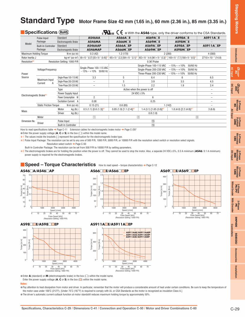
Standard Type Motor Frame Size 42 mm (1.65 in.), 60 mm (2.36 in.), 85 mm (3.35 in.)
Specifications ■ With the ● AS46 type, only the driver conforms to the CSA Standards.
Model
Pulse Input Package
Standard AS46AA AS66A□E AS69A□E AS98A□E AS911A□EElectromagnetic Brake AS46MA AS66M□E AS69M□E AS98M□E −
Built-In ControllerPackage
Standard AS46AAP AS66A□EP AS69A□EP AS98A□EP AS911A□EPElectromagnetic Brake AS46MAP AS66M□EP AS69M□EP AS98M□EP −
Maximum Holding Torque N·m (oz-in) 0.3 (42) 1.2 (170) 2 (280) 4 (560)Rotor Inertia J kg·m2 (oz-in2) 68×10−7 (0.37) [83×10−7 (0.45)]✽1 405×10−7 (2.2) [564×10−7 (3.1)]✽1 802×10−7 (4.4) [961×10−7 (5.3)]✽1 1400×10−7 (7.7) [1560×10−7 (8.5)]✽1 2710×10−7 (14.8)Resolution✽2 Resolution Setting: 1000 P/R 0.36˚/Pulse
PowerSource
Voltage/FrequencySingle-Phase 100-115 VAC −15%∼+10% 50/60 Hz
Single-Phase 100-115 VAC −15%∼+10% 50/60 HzSingle-Phase 200-230 VAC −15%∼+10% 50/60 HzThree-Phase 200-230 VAC −15%∼+10% 50/60 Hz
Maximum InputCurrent A
Single-Phase 100-115 VAC 3.3 5 6.4 6 6.5Single-Phase 200-230 VAC – 3 3.9 3.5 4.5Three-Phase 200-230 VAC – 1.5 2.2 1.9 2.4
Electromagnetic Brake✽3
Type Active when the power is off –Power Supply Input 24 VDC±5% –Power Consumption W 2 6 –Excitation Current A 0.08 0.25 –
Static Friction Torque N·m (oz-in) 0.15 (21) 0.6 (85) 1 (142) –
MassMotor kg (lb.) 0.5 (1.1) [0.6 (1.3)]✽1 0.85 (1.9) [1.1 (2.4)]✽1 1.4 (3.1) [1.65 (3.6)]✽1 1.8 (4.0) [2.2 (4.8)]✽1 3 (6.6)Driver kg (lb.) 0.8 (1.8)
Dimension No.Motor □1 □2 □3
DriverPulse Input □15
Built-In Controller □16
How to read specifications table ➜ Page C-11 Extension cables for electromagnetic brake motor ➜ Page C-297Enter the power supply voltage ( ● A, C or S) in the box (□) within the model name.1 ✽ The values inside the brackets [ ] represent the specification for the electromagnetic brake type.2 ✽ Pulse Input Package: The resolution can be set to any one of 500 P/R, 1000 P/R, 5000 P/R, or 10000 P/R with the resolution select switch or resolution select signals.
Resolution select switch ➜ Page C-50Built-In Controller Package: The resolution can be set from 500 P/R to 10000 P/R by setting parameters.
3 ✽ The electromagnetic brakes are for holding the position when the power is off. They cannot be used to stop the motor. Also, a separate 24 VDC±5%, 0.3 A minimum (AS46: 0.1 A minimum) power supply is required for the electromagnetic brakes.
Speed – Torque Characteristics ■ How to read speed – torque characteristics ➜ Page C-12
AS46□A/AS46□AP
1000 2000 3000 4000
100 20 30 40 50 60 70
0.4
0.5
0.2
0.1
0.3
00
0
20
30
40
50
60
70
10
Torq
ue [o
z-in
]
Speed [r/min]
Torq
ue [N
·m]
Pulse Speed [kHz](Resolution Setting: 1000 P/R)
AS66□■□E/AS66□■□EP
10000 2000 3000 4000
Torq
ue [N
·m]
Torq
ue [o
z-in
]
Speed [r/min]
Pulse Speed [kHz]100 20 30 40 50 60 70
(Resolution Setting: 1000 P/R)
1.5
2.0
1.0
0.5
0
250
200
150
100
50
0
AS69□■□E/AS69□■□EP
10000 2000 3000 4000
100 20 30 40 50 60 70
2
3
1
0
Torq
ue [N
·m]
Torq
ue [o
z-in
]
Speed [r/min]
Pulse Speed [kHz](Resolution Setting: 1000 P/R)
400
300
200
100
0
Enter ● A (standard) or M (electromagnetic brake) in the box (□) within the model name.Enter the power supply voltage (A, C or S) in the box (■□) within the model name.
Notes:
Pay attention to heat dissipation from motor and driver. In particular, remember that the motor will produce a considerable amount of heat under certain conditions. Be sure to keep the temperature of ●the motor case under 100˚C (212˚F). [Under 75˚C (167˚F) is required to comply with UL or CSA Standards as the motor is recognized as insulation Class A.]The driver's automatic current cutback function at motor standstill reduces maximum holding torque by approximately 50%. ●
AS98□■□E/AS98□■□EP
10000 2000 3000 4000
100 20 30 40 50 60 70
2
3
1
0
Torq
ue [N
·m]
Torq
ue [o
z-in
]
Speed [r/min]
Pulse Speed [kHz](Resolution Setting: 1000 P/R)
400
300
200
100
0
AS911A■□E/AS911A■□EP
10000 2000 3000 4000
100 20 30 40 50 60 70
4
5
2
1
3
0
AS911AAE/AS911AAEP AS911ACE/AS911ACEP AS911ASE/AS911ASEP
Torq
ue [N
·m]
Torq
ue [o
z-in
]
Speed [r/min]
Pulse Speed [kHz](Resolution Setting: 1000 P/R)
600
400
200
0
Ste
pp
ing
Mo
tors
C-30 ORIENTAL MOTOR GENERAL CATALOG 2009/2010 Features C-14 / System Configuration C-20 / Product Line C-25
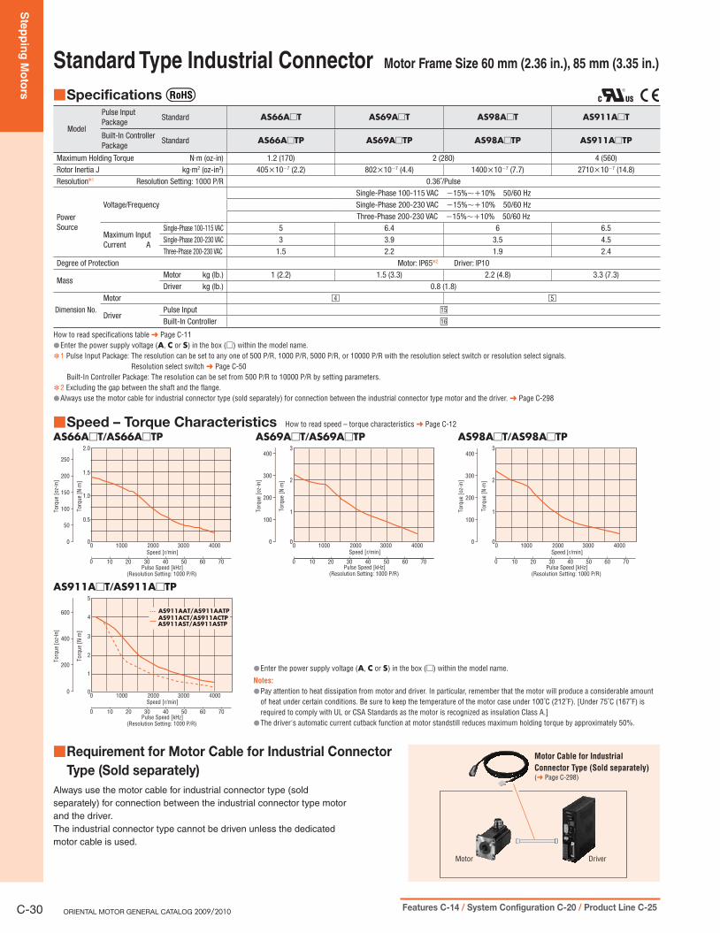
Standard Type Industrial Connector Motor Frame Size 60 mm (2.36 in.), 85 mm (3.35 in.)
Specifications ■
Model
Pulse Input Package
Standard AS66A□T AS69A□T AS98A□T AS911A□T
Built-In ControllerPackage
Standard AS66A□TP AS69A□TP AS98A□TP AS911A□TP
Maximum Holding Torque N·m (oz-in) 1.2 (170) 2 (280) 4 (560)Rotor Inertia J kg·m2 (oz-in2) 405×10−7 (2.2) 802×10−7 (4.4) 1400×10−7 (7.7) 2710×10−7 (14.8)Resolution✽1 Resolution Setting: 1000 P/R 0.36˚/Pulse
PowerSource
Voltage/FrequencySingle-Phase 100-115 VAC −15%∼+10% 50/60 HzSingle-Phase 200-230 VAC −15%∼+10% 50/60 HzThree-Phase 200-230 VAC −15%∼+10% 50/60 Hz
Maximum InputCurrent A
Single-Phase 100-115 VAC 5 6.4 6 6.5Single-Phase 200-230 VAC 3 3.9 3.5 4.5Three-Phase 200-230 VAC 1.5 2.2 1.9 2.4
Degree of Protection Motor: IP65✽2 Driver: IP10
MassMotor kg (lb.) 1 (2.2) 1.5 (3.3) 2.2 (4.8) 3.3 (7.3)Driver kg (lb.) 0.8 (1.8)
Dimension No.Motor □4 □5
DriverPulse Input □15
Built-In Controller □16
How to read specifications table ➜ Page C-11Enter the power supply voltage ( ● A, C or S) in the box (□) within the model name.1 ✽ Pulse Input Package: The resolution can be set to any one of 500 P/R, 1000 P/R, 5000 P/R, or 10000 P/R with the resolution select switch or resolution select signals.
Resolution select switch ➜ Page C-50Built-In Controller Package: The resolution can be set from 500 P/R to 10000 P/R by setting parameters.
2 ✽ Excluding the gap between the shaft and the flange.Always use the motor cable for industrial connector type (sold separately) for connection between the industrial connector type motor and the driver. ● ➜ Page C-298
Speed – Torque Characteristics ■ How to read speed – torque characteristics ➜ Page C-12
AS66A□T/AS66A□TP
10000 2000 3000 4000
Torq
ue [N
·m]
Torq
ue [o
z-in
]
Speed [r/min]
Pulse Speed [kHz]100 20 30 40 50 60 70
(Resolution Setting: 1000 P/R)
1.5
2.0
1.0
0.5
0
250
200
150
100
50
0
AS69A□T/AS69A□TP
10000 2000 3000 4000
100 20 30 40 50 60 70
2
3
1
0
Torq
ue [N
·m]
Torq
ue [o
z-in
]
Speed [r/min]
Pulse Speed [kHz](Resolution Setting: 1000 P/R)
400
300
200
100
0
AS98A□T/AS98A□TP
10000 2000 3000 4000
100 20 30 40 50 60 70
2
3
1
0
Torq
ue [N
·m]
Torq
ue [o
z-in
]
Speed [r/min]
Pulse Speed [kHz](Resolution Setting: 1000 P/R)
400
300
200
100
0
■Requirement for Motor Cable for Industrial ConnectorType (Sold separately)
Always use the motor cable for industrial connector type (sold
separately) for connection between the industrial connector type motor
and the driver.
The industrial connector type cannot be driven unless the dedicated
motor cable is used.
Motor Driver
Motor Cable for Industrial
Connector Type (Sold separately)(➜ Page C-298)
AS911A□T/AS911A□TP
10000 2000 3000 4000
100 20 30 40 50 60 70
4
5
2
1
3
0
AS911AAT/AS911AATP AS911ACT/AS911ACTP AS911AST/AS911ASTP
Torq
ue [N
·m]
Torq
ue [o
z-in
]
Speed [r/min]
Pulse Speed [kHz](Resolution Setting: 1000 P/R)
600
400
200
0
Enter the power supply voltage ( ● A, C or S) in the box (□) within the model name.
Notes:
Pay attention to heat dissipation from motor and driver. In particular, remember that the motor will produce a considerable amount ●of heat under certain conditions. Be sure to keep the temperature of the motor case under 100˚C (212˚F). [Under 75˚C (167˚F) is required to comply with UL or CSA Standards as the motor is recognized as insulation Class A.]The driver's automatic current cutback function at motor standstill reduces maximum holding torque by approximately 50%. ●

Ste
pp
ing
Mo
tors
Intro
du
ctio
nA
SA
SC5-P
hase
Mic
roste
pRK
2-P
hase
Fu
ll/Half
UM
K
5-P
hase
Mic
roste
pCRK
2-P
hase
Mic
roste
pRBK
2-P
hase
Mic
roste
pCM
K2-P
hase
PK
/PV
2-P
ha
se
PK
EMP40
0SG
803
0J
Accesso
ries
Insta
llatio
n
AC
Inp
ut
DC
Inp
ut
AC
Inp
ut
DC
Inp
ut
Without E
ncoderW
ith E
nc
od
er
Co
ntro
llers
C-31Specifications, Characteristics C-29 / Dimensions C-41 / Connection and Operation C-50 / Motor and Driver Combinations C-60
TH Geared Type Motor Frame Size 42 mm (1.65 in.)
Specifications ■ With the ● AS46 type, only the driver conforms to the CSA Standards.
ModelPulse Input Package
Standard AS46AA-T3.6 AS46AA-T7.2 AS46AA-T10 AS46AA-T20 AS46AA-T30Electromagnetic Brake AS46MA-T3.6 AS46MA-T7.2 AS46MA-T10 AS46MA-T20 AS46MA-T30
Built-In ControllerPackage
Standard AS46AAP-T3.6 AS46AAP-T7.2 AS46AAP-T10 AS46AAP-T20 AS46AAP-T30Electromagnetic Brake AS46MAP-T3.6 AS46MAP-T7.2 AS46MAP-T10 AS46MAP-T20 AS46MAP-T30
Maximum Holding Torque N·m (lb-in) 0.35 (3) 0.7 (6.1) 1 (8.8) 1.5 (13.2)Rotor Inertia J kg·m2 (oz-in2) 68×10−7 (0.37) [83×10−7 (0.45)]✽1
Backlash arc minute (degrees) 45 (0.75˚) 25 (0.417˚) 25 (0.417˚) 15 (0.25˚) 15 (0.25˚)Permissible Speed Range r/min 0∼500 0∼250 0∼180 0∼90 0∼60Gear Ratio 3.6:1 7.2:1 10:1 20:1 30:1Resolution✽2 Resolution Setting: 1000 P/R 0.1˚/Pulse 0.05˚/Pulse 0.036˚/Pulse 0.018˚/Pulse 0.012˚/PulsePermissible Torque N·m (lb-in) 0.35 (3) 0.7 (6.1) 1 (8.8) 1.5 (13.2)
PowerSource
Voltage/Frequency Single-Phase 100-115 VAC −15%∼+10% 50/60 HzMaximum Input Current A Single-Phase 100-115 VAC 3.3
Electromagnetic Brake✽3
Type Active when the power is offPower Supply Input 24 VDC±5%Power Consumption W 2Excitation Current A 0.08
Static Friction Torque N·m (lb-in) 0.17 (1.5) 0.35 (3) 0.5 (4.4) 0.75 (6.6)
MassMotor kg (lb.) 0.65 (1.4) [0.75 (1.7)]✽1
Driver kg (lb.) 0.8 (1.8)
Dimension No.Motor □6
DriverPulse Input □15
Built-In Controller □16
How to read specifications table ➜ Page C-111 ✽ The values inside the brackets [ ] represent the specification for the electromagnetic brake type.2 ✽ Pulse Input Package: The resolution can be set to any one of 500 P/R, 1000 P/R, 5000 P/R, or 10000 P/R with the resolution select switch or resolution select signals.
Resolution select switch ➜ Page C-50Built-In Controller Package: The resolution can be set from 500 P/R to 10000 P/R by setting parameters.
3 ✽ The electromagnetic brakes are for holding the position when the power is off. They cannot be used to stop the motor. Also, a separate 24 VDC±5%, 0.1 A minimum power supply is required for the electromagnetic brakes.
Note:
Direction of rotation of the motor and that of the gear output shaft are the same for the gear ratios 3.6:1, 7.2:1 and 10:1. It is opposite for 20:1 and 30:1 gear ratios. ●
Speed – Torque Characteristics ■ How to read speed – torque characteristics ➜ Page C-12
AS46□A-T3.6/AS46□AP-T3.6
0
0 100 200 300 400 500
2015 3025105
600Speed [r/min]
Torq
ue [N
·m]
0
0.5
0.4
0.3
0.2
0.1
35Pulse Speed [kHz]
(Resolution Setting: 1000 P/R)
0
2
3
4
1
Torq
ue [l
b-in
]
Permissible Torque
AS46□A-T20/AS46□AP-T20
20 40 60 80 100
2.0
50 10 15 20 25 30
1.5
1.0
0.5
00
0
10
15
5
Torq
ue [l
b-in
]
Speed [r/min]
Pulse Speed [kHz](Resolution Setting: 1000 P/R)
Torq
ue [N
·m]
Permissible Torque
AS46□A-T7.2/AS46□AP-T7.2
0
0 100 200
2015 3025105
3000
1.0
0.8
0.6
0.4
0.2
35
Speed [r/min]
Pulse Speed [kHz](Resolution Setting: 1000 P/R)
0
4
6
8
2
Torq
ue [l
b-in
]
Torq
ue [N
·m]
Permissible Torque
AS46□A-T30/AS46□AP-T30
0
0 10 20 30 40 50 60
2015 25105
700
2.0
1.5
0.5
1.0
30 35
0
10
15
5
Torq
ue [l
b-in
]
Speed [r/min]
Pulse Speed [kHz](Resolution Setting: 1000 P/R)
Torq
ue [N
·m]
Permissible Torque
AS46□A-T10/AS46□AP-T10
0
0 50 150100
2015 25105
2000
1.2
1.0
0.8
0.6
0.4
0.2
30
Speed [r/min]
Pulse Speed [kHz](Resolution Setting: 1000 P/R)
Torq
ue [N
·m]
0
2
4
6
8
10
Torq
ue [l
b-in
]
Permissible Torque
Enter ● A (standard) or M (electromagnetic brake) in the box (□) within the model name.
Notes:
Pay attention to heat dissipation from motor and driver. In particular, remember that the motor will produce a considerable amount of heat under certain conditions. Be sure to keep the temperature ●of the motor case under 100˚C (212˚F). [Under 75˚C (167˚F) is required to comply with UL or CSA Standards as the motor is recognized as insulation Class A.]The driver's automatic current cutback function at motor standstill reduces maximum holding torque by approximately 50%. ●

Ste
pp
ing
Mo
tors
C-32 ORIENTAL MOTOR GENERAL CATALOG 2009/2010 Features C-14 / System Configuration C-20 / Product Line C-25
TH Geared Type Motor Frame Size 60 mm (2.36 in.)
Specifications ■
Model
Pulse Input Package
Standard AS66A□E-T3.6 AS66A□E-T7.2 AS66A□E-T10 AS66A□E-T20 AS66A□E-T30Electromagnetic Brake AS66M□E-T3.6 AS66M□E-T7.2 AS66M□E-T10 AS66M□E-T20 AS66M□E-T30
Built-In ControllerPackage
Standard AS66A□EP-T3.6 AS66A□EP-T7.2 AS66A□EP-T10 AS66A□EP-T20 AS66A□EP-T30Electromagnetic Brake AS66M□EP-T3.6 AS66M□EP-T7.2 AS66M□EP-T10 AS66M□EP-T20 AS66M□EP-T30
Maximum Holding Torque N·m (lb-in) 1.25 (11) 2.5 (22) 3 (26) 3.5 (30) 4 (35)Rotor Inertia J kg·m2 (oz-in2) 405×10−7 (2.2) [564×10−7 (3.1)]✽1
Backlash arc minute (degrees) 35 (0.584˚) 15 (0.25˚) 10 (0.167˚)Permissible Speed Range r/min 0∼500 0∼250 0∼180 0∼90 0∼60 Gear Ratio 3.6:1 7.2:1 10:1 20:1 30:1Resolution✽2 Resolution Setting: 1000 P/R 0.1˚/Pulse 0.05˚/Pulse 0.036˚/Pulse 0.018˚/Pulse 0.012˚/PulsePermissible Torque N·m (lb-in) 1.25 (11) 2.5 (22) 3 (26) 3.5 (30) 4 (35)
PowerSource
Voltage/FrequencySingle-Phase 100-115 VAC −15%∼+10% 50/60 HzSingle-Phase 200-230 VAC −15%∼+10% 50/60 HzThree-Phase 200-230 VAC −15%∼+10% 50/60 Hz
Maximum InputCurrent A
Single-Phase 100-115 VAC 5Single-Phase 200-230 VAC 3Three-Phase 200-230 VAC 1.5
Electromagnetic Brake✽3
Type Active when the power is offPower Supply Input 24 VDC±5%Power Consumption W 6Excitation Current A 0.25
Static Friction Torque N·m (lb-in) 0.62 (5.4) 1.25 (11) 1.5 (13.2) 1.75 (15.4) 2 (17.7)
MassMotor kg (lb.) 1.25 (2.8) [1.5 (3.3)]✽1
Driver kg (lb.) 0.8 (1.8)
Dimension No.Motor □7
DriverPulse Input □15
Built-In Controller □16
How to read specifications table ➜ Page C-11 Extension cables for electromagnetic brake motor ➜ Page C-297Enter the power supply voltage ( ● A, C or S) in the box (□) within the model name.1 ✽ The values inside the brackets [ ] represent the specification for the electromagnetic brake type.2 ✽ Pulse Input Package: The resolution can be set to any one of 500 P/R, 1000 P/R, 5000 P/R, or 10000 P/R with the resolution select switch or resolution select signals.
Resolution select switch ➜ Page C-50Built-In Controller Package: The resolution can be set from 500 P/R to 10000 P/R by setting parameters.
3 ✽ The electromagnetic brakes are for holding the position when the power is off. They cannot be used to stop the motor. Also, a separate 24 VDC±5%, 0.3 A minimum power supply is required for the electromagnetic brakes.
Note:
Direction of rotation of the motor and that of the gear output shaft are the same for the gear ratios 3.6:1, 7.2:1 and 10:1. It is opposite for 20:1 and 30:1 gear ratios. ●
Speed – Torque Characteristics ■ How to read speed – torque characteristics ➜ Page C-12
AS66□■□E-T3.6/AS66□■□EP-T3.6
0
0 100 200 300 400 500
2015 3025105
6000
1.5
1.0
0.5
35
Speed [r/min]
Pulse Speed [kHz](Resolution Setting: 1000 P/R)
Torq
ue [N
·m]
0
8
12
4
Torq
ue [l
b-in
]
10
6
2
Permissible Torque
AS66□■□E-T20/AS66□■□EP-T20
20 40 60 80 100
50 10 15 20 25 30
4
3
5
2
1
00Speed [r/min]
Pulse Speed [kHz](Resolution Setting: 1000 P/R)
Torq
ue [N
·m]
0
20
30
40
10
Torq
ue [l
b-in
]
Permissible Torque
AS66□■□E-T7.2/AS66□■□EP-T7.2
0
0 10050 150 200 250
2015 3025105
3000
4
3
2
1
35
Speed [r/min]
Pulse Speed [kHz](Resolution Setting: 1000 P/R)
Torq
ue [N
·m]
0
20
30
10
Torq
ue [l
b-in
]
Permissible Torque
AS66□■□E-T30/AS66□■□EP-T30
00
5
4
3
2
1
0
10 20 30 40 50 60
2015 25105
70
30 35
Speed [r/min]
Pulse Speed [kHz](Resolution Setting: 1000 P/R)
0
20
30
40
10
Torq
ue [l
b-in
]
Torq
ue [N
·m]
Permissible Torque
AS66□■□E-T10/AS66□■□EP-T10
40 80 120 160 200
4
50 10 15 20 25 30
3
5
2
1
00
Speed [r/min]
Pulse Speed [kHz](Resolution Setting: 1000 P/R)
Torq
ue [N
·m]
0
20
30
40
10
Torq
ue [l
b-in
] Permissible Torque
Enter ● A (standard) or M (electromagnetic brake) in the box (□) within the model name.Enter the power supply voltage (A, C or S) in the box (■□) within the model name.
Notes:
Pay attention to heat dissipation from motor and driver. In particular, remember that the motor will produce a considerable amount of heat under certain conditions. Be sure to keep the temperature of ●the motor case under 100˚C (212˚F). [Under 75˚C (167˚F) is required to comply with UL or CSA Standards as the motor is recognized as insulation Class A.]The driver's automatic current cutback function at motor standstill reduces maximum holding torque by approximately 50%. ●

Ste
pp
ing
Mo
tors
Intro
du
ctio
nA
SA
SC5-P
hase
Mic
roste
pRK
2-P
hase
Fu
ll/Half
UM
K
5-P
hase
Mic
roste
pCRK
2-P
hase
Mic
roste
pRBK
2-P
hase
Mic
roste
pCM
K2-P
hase
PK
/PV
2-P
ha
se
PK
EMP40
0SG
803
0J
Accesso
ries
Insta
llatio
n
AC
Inp
ut
DC
Inp
ut
AC
Inp
ut
DC
Inp
ut
Without E
ncoderW
ith E
nc
od
er
Co
ntro
llers
C-33Specifications, Characteristics C-29 / Dimensions C-41 / Connection and Operation C-50 / Motor and Driver Combinations C-60
TH Geared Type Motor Frame Size 90 mm (3.54 in.)
Specifications ■
Model
Pulse Input Package
Standard AS98A□E-T3.6 AS98A□E-T7.2 AS98A□E-T10 AS98A□E-T20 AS98A□E-T30Electromagnetic Brake AS98M□E-T3.6 AS98M□E-T7.2 AS98M□E-T10 AS98M□E-T20 AS98M□E-T30
Built-In ControllerPackage
Standard AS98A□EP-T3.6 AS98A□EP-T7.2 AS98A□EP-T10 AS98A□EP-T20 AS98A□EP-T30Electromagnetic Brake AS98M□EP-T3.6 AS98M□EP-T7.2 AS98M□EP-T10 AS98M□EP-T20 AS98M□EP-T30
Maximum Holding Torque N·m (lb-in) 4.5 (39) 9 (79) 12 (106)Rotor Inertia J kg·m2 (oz-in2) 1400×10−7 (7.7) [1560×10−7 (8.5)]✽1
Backlash arc minute (degrees) 25 (0.417˚) 15 (0.25˚) 10 (0.167˚)Permissible Speed Range r/min 0∼500 0∼250 0∼180 0∼90 0∼60 Gear Ratio 3.6:1 7.2:1 10:1 20:1 30:1Resolution✽2 Resolution Setting: 1000 P/R 0.1˚/Pulse 0.05˚/Pulse 0.036˚/Pulse 0.018˚/Pulse 0.012˚/PulsePermissible Torque N·m (lb-in) 4.5 (39) 9 (79) 12 (106)
PowerSource
Voltage/FrequencySingle-Phase 100-115 VAC −15%∼+10% 50/60 HzSingle-Phase 200-230 VAC −15%∼+10% 50/60 HzThree-Phase 200-230 VAC −15%∼+10% 50/60 Hz
Maximum InputCurrent A
Single-Phase 100-115 VAC 6Single-Phase 200-230 VAC 3.5Three-Phase 200-230 VAC 1.9
Electromagnetic Brake✽3
Type Active when the power is offPower Supply Input 24 VDC±5%Power Consumption W 6Excitation Current A 0.25
Static Friction Torque N·m (lb-in) 2.25 (19.9) 4.5 (39) 6 (53)
MassMotor kg (lb.) 3 (6.6) [3.4 (7.5)]✽1
Driver kg (lb.) 0.8 (1.8)
Dimension No.Motor □8
DriverPulse Input □15
Built-In Controller □16
How to read specifications table ➜ Page C-11 Extension cables for electromagnetic brake motor ➜ Page C-297Enter the power supply voltage ( ● A, C or S) in the box (□) within the model name.1 ✽ The values inside the brackets [ ] represent the specification for the electromagnetic brake type.2 ✽ Pulse Input Package: The resolution can be set to any one of 500 P/R, 1000 P/R, 5000 P/R, or 10000 P/R with the resolution select switch or resolution select signals.
Resolution select switch ➜ Page C-50Built-In Controller Package: The resolution can be set from 500 P/R to 10000 P/R by setting parameters.
3 ✽ The electromagnetic brakes are for holding the position when the power is off. They cannot be used to stop the motor. Also, a separate 24 VDC±5%, 0.3 A minimum power supply is required for the electromagnetic brakes.
Note:
Direction of rotation of the motor and that of the gear output shaft are the same for the gear ratios 3.6:1, 7.2:1 and 10:1. It is opposite for 20:1 and 30:1 gear ratios. ●
Speed – Torque Characteristics ■ How to read speed – torque characteristics ➜ Page C-12
AS98□■□E-T3.6/AS98□■□EP-T3.6
0
0 100 200 300 400 500
2015 3025105
6000
6
5
4
3
2
1
35
Speed [r/min]
Pulse Speed [kHz](Resolution Setting: 1000 P/R)
Torq
ue [N
·m]
0
10
20
30
40
50
Torq
ue [l
b-in
]
Permissible Torque
AS98□■□E-T20/AS98□■□EP-T20
20 40 60 80 100
15
50 10 15 20 25 30
10
5
00
Speed [r/min]
Pulse Speed [kHz](Resolution Setting: 1000 P/R)
Torq
ue [N
·m]
0
80
120
40
Torq
ue [l
b-in
]
100
60
20
Permissible Torque
AS98□■□E-T7.2/AS98□■□EP-T7.2
0 10050 150 200 250 3000
12
10
8
6
4
2
0 2015 3025105 35
Speed [r/min]
Pulse Speed [kHz](Resolution Setting: 1000 P/R)
Torq
ue [N
·m]
0
20
40
60
80
100
Torq
ue [l
b-in
]
Permissible Torque
AS98□■□E-T30/AS98□■□EP-T30
0
0 10 20 30 40 50 60
2015 25105
700
15
10
5
30 35
Speed [r/min]
Pulse Speed [kHz](Resolution Setting: 1000 P/R)
Torq
ue [N
·m]
0
80
120
40
Torq
ue [l
b-in
]
100
60
20
Permissible Torque
AS98□■□E-T10/AS98□■□EP-T10
40 80 120 160 200
50 10 15 20 25 30
8
10
12
4
6
2
00Speed [r/min]
Pulse Speed [kHz](Resolution Setting: 1000 P/R)
Torq
ue [N
·m]
0
20
40
60
80
100
Torq
ue [l
b-in
]
Permissible Torque
Enter ● A (standard) or M (electromagnetic brake) in the box (□) within the model name.Enter the power supply voltage (A, C or S) in the box (■□) within the model name.
Notes:
Pay attention to heat dissipation from motor and driver. In particular, remember that the motor will produce a considerable amount of heat under certain conditions. Be sure to keep the temperature of ●the motor case under 100˚C (212˚F). [Under 75˚C (167˚F) is required to comply with UL or CSA Standards as the motor is recognized as insulation Class A.]The driver's automatic current cutback function at motor standstill reduces maximum holding torque by approximately 50%. ●

Ste
pp
ing
Mo
tors
C-34 ORIENTAL MOTOR GENERAL CATALOG 2009/2010 Features C-14 / System Configuration C-20 / Product Line C-25
PN Geared Type Motor Frame Size 42 mm (1.65 in.)
Specifications ■ With the ● AS46 type, only the driver conforms to the CSA Standards.
Model
Pulse Input Package
Standard AS46AA-N7.2 AS46AA-N10Electromagnetic Brake AS46MA-N7.2 AS46MA-N10
Built-In ControllerPackage
Standard AS46AAP-N7.2 AS46AAP-N10Electromagnetic Brake AS46MAP-N7.2 AS46MAP-N10
Maximum Holding Torque N·m (lb-in) 1.5 (13.2)Rotor Inertia J kg·m2 (oz-in2) 68×10−7 (0.37) [83×10−7 (0.45)]✽1
Backlash arc minute (degrees) 2 (0.034˚)Angular Transmission Error arc minute (degrees) 6 (0.1˚)Permissible Speed Range r/min 0∼416 0∼300Gear Ratio 7.2:1 10:1Resolution✽2 Resolution Setting: 1000 P/R 0.05˚/Pulse 0.036˚/PulsePermissible Torque N·m (lb-in) 1.5 (13.2)Maximum Torque✽3 N·m (lb-in) 2 (17.7)
PowerSource
Voltage/Frequency Single-Phase 100-115 VAC −15%∼+10% 50/60 HzMaximum Input Current A Single-Phase 100-115 VAC 3.3
Electromagnetic Brake✽4
Type Active when the power is offPower Supply Input 24 VDC±5%Power Consumption W 2Excitation Current A 0.08
Static Friction Torque N·m (lb-in) 0.75 (6.6)
MassMotor kg (lb.) 0.71 (1.6) [0.81 (1.8)]✽1
Driver kg (lb.) 0.8 (1.8)
Dimension No.Motor □9
DriverPulse Input □15
Built-In Controller □16
How to read specifications table ➜ Page C-111 ✽ The values inside the brackets [ ] represent the specification for the electromagnetic brake type.2 ✽ Pulse Input Package: The resolution can be set to any one of 500 P/R, 1000 P/R, 5000 P/R, or 10000 P/R with the resolution select switch or resolution select signals.
Resolution select switch ➜ Page C-50Built-In Controller Package: The resolution can be set from 500 P/R to 10000 P/R by setting parameters.
3 ✽ The value of maximum torque is for gear. For output torque for geared motor, refer to the speed – torque characteristics.4 ✽ The electromagnetic brakes are for holding the position when the power is off. They cannot be used to stop the motor. Also, a separate 24 VDC±5%, 0.1 A minimum power supply is required for
the electromagnetic brakes.
Note:
Direction of rotation of the motor shaft and that of the gear output shaft are the same. ●
Speed – Torque Characteristics ■ How to read speed – torque characteristics ➜ Page C-12
AS46□A-N7.2/AS46□AP-N7.2
0
0 100 200 300 400
3020 4010
0
2.5
2.0
1.5
1.0
0.5
50
0
10
15
20
5
Torq
ue [l
b-in
]
Speed [r/min]
Pulse Speed [kHz](Resolution Setting: 1000 P/R)
Torq
ue [N
·m]
Maximum Torque
Permissible Torque
AS46□A-N10/AS46□AP-N10
0
0 100 200 300
4020 3010
0
2.5
2.0
1.0
1.5
0.5
50
0
10
15
20
5
Torq
ue [l
b-in
]
Speed [r/min]
Pulse Speed [kHz](Resolution Setting: 1000 P/R)
Torq
ue [N
·m]
Maximum Torque
Permissible Torque
Enter ● A (standard) or M (electromagnetic brake) in the box (□) within the model name.
Notes:
Pay attention to heat dissipation from motor and driver. In particular, remember that the motor will produce a considerable amount of heat under certain conditions. Be sure to keep the temperature of ●the motor case under 100˚C (212˚F). [Under 75˚C (167˚F) is required to comply with UL or CSA Standards as the motor is recognized as insulation Class A.]The driver's automatic current cutback function at motor standstill reduces maximum holding torque by approximately 50%. ●

Ste
pp
ing
Mo
tors
Intro
du
ctio
nA
SA
SC5-P
hase
Mic
roste
pRK
2-P
hase
Fu
ll/Half
UM
K
5-P
hase
Mic
roste
pCRK
2-P
hase
Mic
roste
pRBK
2-P
hase
Mic
roste
pCM
K2-P
hase
PK
/PV
2-P
hase
PK
EMP4
00
SG8
03
0J
Accesso
ries
Insta
llatio
n
AC
Inp
ut
DC
Inp
ut
AC
Inp
ut
DC
Inp
ut
Without E
ncoderW
ith E
nc
od
er
Co
ntro
llers
C-35Specifications, Characteristics C-29 / Dimensions C-41 / Connection and Operation C-50 / Motor and Driver Combinations C-60
PN Geared Type Motor Frame Size 60 mm (2.36 in.)
Specifications ■
Model
Pulse Input Package
Standard AS66A□E-N5 AS66A□E-N7.2 AS66A□E-N10 AS66A□E-N25 AS66A□E-N36 AS66A□E-N50Electromagnetic Brake AS66M□E-N5 AS66M□E-N7.2 AS66M□E-N10 AS66M□E-N25 AS66M□E-N36 AS66M□E-N50
Built-In ControllerPackage
Standard AS66A□EP-N5 AS66A□EP-N7.2 AS66A□EP-N10 AS66A□EP-N25 AS66A□EP-N36 AS66A□EP-N50Electromagnetic Brake AS66M□EP-N5 AS66M□EP-N7.2 AS66M□EP-N10 AS66M□EP-N25 AS66M□EP-N36 AS66M□EP-N50
Maximum Holding Torque N·m (lb-in) 3.5 (30) 4 (35) 5 (44) 8 (70)Rotor Inertia J kg·m2 (oz-in2) 405×10−7 (2.2) [564×10−7 (3.1)]✽1
Backlash arc minute (degrees) 2 (0.034˚) 3 (0.05˚)Angular Transmission Error arc minute (degrees) 5 (0.084˚)Permissible Speed Range r/min 0∼600 0∼416 0∼300 0∼120 0∼83 0∼60Gear Ratio 5:1 7.2:1 10:1 25:1 36:1 50:1Resolution✽2 Resolution Setting: 1000 P/R 0.072˚/Pulse 0.05˚/Pulse 0.036˚/Pulse 0.0144˚/Pulse 0.01˚/Pulse 0.0072˚/PulsePermissible Torque N·m (lb-in) 3.5 (30) 4 (35) 5 (44) 8 (70)Maximum Torque✽3 N·m (lb-in) 7 (61) 9 (79) 11 (97) 16 (141) 20 (177)
PowerSource
Voltage/FrequencySingle-Phase 100-115 VAC −15%∼+10% 50/60 HzSingle-Phase 200-230 VAC −15%∼+10% 50/60 HzThree-Phase 200-230 VAC −15%∼+10% 50/60 Hz
Maximum InputCurrent A
Single-Phase 100-115 VAC 5Single-Phase 200-230 VAC 3Three-Phase 200-230 VAC 1.5
Electromagnetic Brake✽4
Type Active when the power is offPower Supply Input 24 VDC±5%Power Consumption W 6Excitation Current A 0.25
Static Friction Torque N·m (lb-in) 1.75 (15.4) 2 (17.7) 2.5 (22) 4 (35)
MassMotor kg (lb.) 1.5 (3.3) [1.75 (3.9)]✽1 1.7 (3.7) [1.95 (4.3)]✽1
Driver kg (lb.) 0.8 (1.8)
Dimension No.Motor □10
DriverPulse Input □15
Built-In Controller □16
How to read specifications table ➜ Page C-11 Extension cables for electromagnetic brake motor ➜ Page C-297Enter the power supply voltage ( ● A, C or S) in the box (□) within the model name.1 ✽ The values inside the brackets [ ] represent the specification for the electromagnetic brake type.2 ✽ Pulse Input Package: The resolution can be set to any one of 500 P/R, 1000 P/R, 5000 P/R, or 10000 P/R with the resolution select switch or resolution select signals.
Resolution select switch ➜ Page C-50Built-In Controller Package: The resolution can be set from 500 P/R to 10000 P/R by setting parameters.
3 ✽ The value of maximum torque is for gear. For output torque for geared motor, refer to the speed – torque characteristics.4 ✽ The electromagnetic brakes are for holding the position when the power is off. They cannot be used to stop the motor. Also, a separate 24 VDC±5%, 0.3 A minimum power supply is required for
the electromagnetic brakes.Note: Direction of rotation of the motor shaft and that of the gear output shaft are the same.
Speed – Torque Characteristics ■ How to read speed – torque characteristics ➜ Page C-12
AS66□■□E-N5/AS66□■□EP-N5
0
0 200 400 600
3020 504010
0
8
6
4
2
Speed [r/min]
Torq
ue [N
·m]
Pulse Speed [kHz](Resolution Setting: 1000 P/R)
0
20
40
60
Torq
ue [l
b-in
]
Permissible Torque
AS66□■□E-N25/AS66□■□EP-N25
0
0 50 100
3020 4010
1500
20
15
10
5
50 60
Speed [r/min]
Pulse Speed [kHz](Resolution Setting: 1000 P/R)
Torq
ue [N
·m]
0
100
150
50
Torq
ue [l
b-in
]
Permissible Torque
AS66□■□E-N7.2/AS66□■□EP-N7.2
0
0 100 200 300 400
3020 4010
0
10
5
50
Speed [r/min]
Torq
ue [N
·m]
Pulse Speed [kHz](Resolution Setting: 1000 P/R)
0
40
60
80
20
Torq
ue [l
b-in
]
Permissible Torque
AS66□■□E-N36/AS66□■□EP-N36
0
0 20 40 60 80
3020 4010
1000
25
20
15
10
5
50
Speed [r/min]
Pulse Speed [kHz](Resolution Setting: 1000 P/R)
0
100
150
200
50
Torq
ue [l
b-in
]
Permissible Torque
Torq
ue [N
·m]
AS66□■□E-N10/AS66□■□EP-N10
0
0 100 200 300
20 30 4010
0
15
10
5
50
Speed [r/min]
Pulse Speed [kHz](Resolution Setting: 1000 P/R)
0
80
120
40
Torq
ue [l
b-in
]
Torq
ue [N
·m]
Permissible Torque
Maximum Torque
AS66□■□E-N50/AS66□■□EP-N50
0
0 10 20 30 40 50 60
3020 4010
700
25
20
15
10
5
50
Speed [r/min]
Pulse Speed [kHz](Resolution Setting: 1000 P/R)
0
100
150
200
50
Torq
ue [l
b-in
]
Torq
ue [N
·m]
Permissible Torque
Maximum Torque
Enter ● A (standard) or M (electromagnetic brake) in the box (□) within the model name. Enter the power supply voltage (A, C or S) in the box (■□) within the model name.
Notes:
Pay attention to heat dissipation from motor and driver. In particular, remember that the motor will produce a considerable amount of heat under certain conditions. Be sure to keep the temperature of ●the motor case under 100˚C (212˚F). [Under 75˚C (167˚F) is required to comply with UL or CSA Standards as the motor is recognized as insulation Class A.]The driver's automatic current cutback function at motor standstill reduces maximum holding torque by approximately 50%. ●
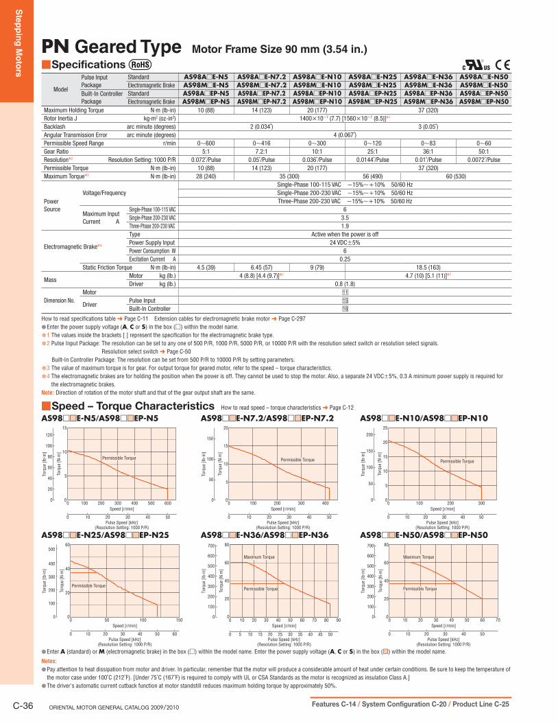
Ste
pp
ing
Mo
tors
C-36 ORIENTAL MOTOR GENERAL CATALOG 2009/2010 Features C-14 / System Configuration C-20 / Product Line C-25
PN Geared Type Motor Frame Size 90 mm (3.54 in.)
Specifications ■
Model
Pulse Input Package
Standard AS98A□E-N5 AS98A□E-N7.2 AS98A□E-N10 AS98A□E-N25 AS98A□E-N36 AS98A□E-N50Electromagnetic Brake AS98M□E-N5 AS98M□E-N7.2 AS98M□E-N10 AS98M□E-N25 AS98M□E-N36 AS98M□E-N50
Built-In ControllerPackage
Standard AS98A□EP-N5 AS98A□EP-N7.2 AS98A□EP-N10 AS98A□EP-N25 AS98A□EP-N36 AS98A□EP-N50Electromagnetic Brake AS98M□EP-N5 AS98M□EP-N7.2 AS98M□EP-N10 AS98M□EP-N25 AS98M□EP-N36 AS98M□EP-N50
Maximum Holding Torque N·m (lb-in) 10 (88) 14 (123) 20 (177) 37 (320)Rotor Inertia J kg·m2 (oz-in2) 1400×10−7 (7.7) [1560×10−7 (8.5)]✽1
Backlash arc minute (degrees) 2 (0.034˚) 3 (0.05˚)Angular Transmission Error arc minute (degrees) 4 (0.067˚)Permissible Speed Range r/min 0∼600 0∼416 0∼300 0∼120 0∼83 0∼60Gear Ratio 5:1 7.2:1 10:1 25:1 36:1 50:1Resolution✽2 Resolution Setting: 1000 P/R 0.072˚/Pulse 0.05˚/Pulse 0.036˚/Pulse 0.0144˚/Pulse 0.01˚/Pulse 0.0072˚/PulsePermissible Torque N·m (lb-in) 10 (88) 14 (123) 20 (177) 37 (320)Maximum Torque✽3 N·m (lb-in) 28 (240) 35 (300) 56 (490) 60 (530)
PowerSource
Voltage/FrequencySingle-Phase 100-115 VAC −15%∼+10% 50/60 HzSingle-Phase 200-230 VAC −15%∼+10% 50/60 HzThree-Phase 200-230 VAC −15%∼+10% 50/60 Hz
Maximum InputCurrent A
Single-Phase 100-115 VAC 6Single-Phase 200-230 VAC 3.5Three-Phase 200-230 VAC 1.9
Electromagnetic Brake✽4
Type Active when the power is offPower Supply Input 24 VDC±5%Power Consumption W 6Excitation Current A 0.25
Static Friction Torque N·m (lb-in) 4.5 (39) 6.45 (57) 9 (79) 18.5 (163)
MassMotor kg (lb.) 4 (8.8) [4.4 (9.7)]✽1 4.7 (10) [5.1 (11)]✽1
Driver kg (lb.) 0.8 (1.8)
Dimension No.Motor □11
DriverPulse Input □15
Built-In Controller □16
How to read specifications table ➜ Page C-11 Extension cables for electromagnetic brake motor ➜ Page C-297Enter the power supply voltage ( ● A, C or S) in the box (□) within the model name.1 ✽ The values inside the brackets [ ] represent the specification for the electromagnetic brake type.2 ✽ Pulse Input Package: The resolution can be set to any one of 500 P/R, 1000 P/R, 5000 P/R, or 10000 P/R with the resolution select switch or resolution select signals.
Resolution select switch ➜ Page C-50Built-In Controller Package: The resolution can be set from 500 P/R to 10000 P/R by setting parameters.
3 ✽ The value of maximum torque is for gear. For output torque for geared motor, refer to the speed – torque characteristics.4 ✽ The electromagnetic brakes are for holding the position when the power is off. They cannot be used to stop the motor. Also, a separate 24 VDC±5%, 0.3 A minimum power supply is required for
the electromagnetic brakes.Note: Direction of rotation of the motor shaft and that of the gear output shaft are the same.
Speed – Torque Characteristics ■ How to read speed – torque characteristics ➜ Page C-12
AS98□■□E-N5/AS98□■□EP-N5
0
0 300200100 400 500 600
3020 4010
0
15
10
5
50
Speed [r/min]
Torq
ue [N
·m]
Pulse Speed [kHz](Resolution Setting: 1000 P/R)
0
80
120
40
Torq
ue [l
b-in
]
100
60
20
Permissible Torque
AS98□■□E-N7.2/AS98□■□EP-N7.2
0
0 100 200 300 400
3020 4010
0
20
15
10
5
50
Speed [r/min]
Pulse Speed [kHz](Resolution Setting: 1000 P/R)
Torq
ue [N
·m]
0
100
150
50
Torq
ue [l
b-in
]
Permissible Torque
AS98□■□E-N10/AS98□■□EP-N10
0
0 100 200 300
3020 4010
0
25
20
15
10
5
50
Speed [r/min]
Pulse Speed [kHz](Resolution Setting: 1000 P/R)
Torq
ue [N
·m]
0
100
150
200
50
Torq
ue [l
b-in
]
Permissible Torque
AS98□■□E-N25/AS98□■□EP-N25
0
0 50 100
3020 4010
1500
60
40
20
50 60
Speed [r/min]
Torq
ue [N
·m]
Pulse Speed [kHz](Resolution Setting: 1000 P/R)
Permissible Torque
0
100
200
300
400
500
Torq
ue [l
b-in
]
AS98□■□E-N36/AS98□■□EP-N36
0
0
503525155 4540302010
504020 3010 7060 90800
80
60
20
40
Speed [r/min]
Pulse Speed [kHz](Resolution Setting: 1000 P/R)
Torq
ue [N
·m]
0
200
300
400
500
600
700
100
Torq
ue [l
b-in
]
Permissible Torque
Maximum Torque
AS98□■□E-N50/AS98□■□EP-N50
00
80
60
40
20
0
10 20 30 40 50 60
3020 4010
70
50
Speed [r/min]
Pulse Speed [kHz](Resolution Setting: 1000 P/R)
Torq
ue [N
·m]
0
200
300
400
500
600
700
100
Torq
ue [l
b-in
]
Permissible Torque
Maximum Torque
Enter ● A (standard) or M (electromagnetic brake) in the box (□) within the model name. Enter the power supply voltage (A, C or S) in the box (■□) within the model name.
Notes:
Pay attention to heat dissipation from motor and driver. In particular, remember that the motor will produce a considerable amount of heat under certain conditions. Be sure to keep the temperature of ●the motor case under 100˚C (212˚F). [Under 75˚C (167˚F) is required to comply with UL or CSA Standards as the motor is recognized as insulation Class A.]The driver's automatic current cutback function at motor standstill reduces maximum holding torque by approximately 50%. ●

Ste
pp
ing
Mo
tors
Intro
du
ctio
nA
SA
SC5-P
hase
Mic
roste
pRK
2-P
hase
Fu
ll/Half
UM
K
5-P
hase
Mic
roste
pCRK
2-P
hase
Mic
roste
pRBK
2-P
hase
Mic
roste
pCM
K2-P
hase
PK
/PV
2-P
ha
se
PK
EMP40
0SG
803
0J
Accesso
ries
Insta
llatio
n
AC
Inp
ut
DC
Inp
ut
AC
Inp
ut
DC
Inp
ut
Without E
ncoderW
ith E
nc
od
er
Co
ntro
llers
C-37Specifications, Characteristics C-29 / Dimensions C-41 / Connection and Operation C-50 / Motor and Driver Combinations C-60
Harmonic Geared Type Motor Frame Size 42 mm (1.65 in.), 60 mm (2.36 in.), 90 mm (3.54 in.)
Specifications ■ With the ● AS46 type, only the driver conforms to the CSA Standards.
Model
Pulse Input Package
Standard AS46AA2-H50 AS46AA2-H100 AS66A□E-H50 AS66A□E-H100 AS98A□E-H50 AS98A□E-H100Electromagnetic Brake AS46MA2-H50 AS46MA2-H100 AS66M□E-H50 AS66M□E-H100 AS98M□E-H50 AS98M□E-H100
Built-In ControllerPackage
Standard AS46AAP2-H50 AS46AAP2-H100 AS66A□EP-H50 AS66A□EP-H100 AS98A□EP-H50 AS98A□EP-H100Electromagnetic Brake AS46MAP2-H50 AS46MAP2-H100 AS66M□EP-H50 AS66M□EP-H100 AS98M□EP-H50 AS98M□EP-H100
Maximum Holding Torque N·m (lb-in) 3.5 (30) 5 (44) 5.5 (48) 8 (70) 25 (220) 37 (320)Rotor Inertia J kg·m2 (oz-in2) 85×10−7 (0.46) [100×10−7 (0.55)]✽1 440×10−7 (2.4) [599×10−7 (3.3)]✽1 1600×10−7 (8.8) [1759×10−7 (9.6)]✽1
Permissible Speed Range r/min 0∼70 0∼35 0∼70 0∼35 0∼70 0∼35Gear Ratio 50:1 100:1 50:1 100:1 50:1 100:1Resolution✽2 Resolution Setting: 1000 P/R 0.0072˚/Pulse 0.0036˚/Pulse 0.0072˚/Pulse 0.0036˚/Pulse 0.0072˚/Pulse 0.0036˚/PulsePermissible Torque N·m (lb-in) 3.5 (30) 5 (44) 5.5 (48) 8 (70) 25 (220) 37 (320)Maximum Torque N·m (lb-in) 8.3 (73) 11 (97) 18 (159) 28 (240) 35 (300) 55 (480)
Lost Motion(Load Torque)
arc minute1.5 max.
(±0.16 N·m)1.5 max.
(±0.2 N·m)0.7 max.
(±0.28 N·m)0.7 max.
(±0.39 N·m)1.5 max.
(±1.2 N·m)
PowerSource
Voltage/FrequencySingle-Phase 100-115 VAC−15%∼+10% 50/60 Hz
Single-Phase 100-115 VAC −15%∼+10% 50/60 HzSingle-Phase 200-230 VAC −15%∼+10% 50/60 HzThree-Phase 200-230 VAC −15%∼+10% 50/60 Hz
Maximum InputCurrent A
Single-Phase 100-115 VAC 3.3 5 6Single-Phase 200-230 VAC – 3 3.5Three-Phase 200-230 VAC – 1.5 1.9
Electromagnetic Brake✽3
Type Active when the power is offPower Supply Input 24 VDC±5%Power Consumption W 2 6Excitation Current A 0.08 0.25
Static Friction Torque N·m (lb-in) 1.75 (15.4) 2.5 (22) 2.75 (24) 4 (35) 12.5 (110) 18.5 (163)
MassMotor kg (lb.) 0.7 (1.5) [0.8 (1.8)]✽1 1.4 (3.1) [1.65 (3.6)]✽1 3.9 (8.6) [4.3 (9.5)]✽1
Driver kg (lb.) 0.8 (1.8)
Dimension No.Motor □12 □13 □14
DriverPulse Input □15
Built-In Controller □16
How to read specifications table ➜ Page C-11 Extension cables for electromagnetic brake motor ➜ Page C-297Enter the power supply voltage ( ● A, C or S) in the box (□) within the model name.1 ✽ The values inside the brackets [ ] represent the specification for the electromagnetic brake type.2 ✽ Pulse Input Package: The resolution can be set to any one of 500 P/R, 1000 P/R, 5000 P/R, or 10000 P/R with the resolution select switch or resolution select signals.
Resolution select switch ➜ Page C-50Built-In Controller Package: The resolution can be set from 500 P/R to 10000 P/R by setting parameters.
3 ✽ The electromagnetic brakes are for holding the position when the power is off. They cannot be used to stop the motor. Also, a separate 24 VDC±5%, 0.3 A minimum (AS46: 0.1 A minimum) power supply is required for the electromagnetic brakes.
Note: The inertia represents a sum of the inertia of the harmonic gear converted to a motor shaft value, and the rotor inertia. Direction of rotation of the motor shaft and that of the gear output shaft are the opposite.
Speed – Torque Characteristics ■ How to read speed – torque characteristics ➜ Page C-12
AS46□A2-H50/AS46□AP2-H50
0
0 20 40 60
3020 4010
800
12
10
6
4
2
8
50 60
Speed [r/min]
Pulse Speed [kHz](Resolution Setting: 1000 P/R)
Torq
ue [N
·m]
0
20
40
60
80
100
Torq
ue [l
b-in
]
Permissible Torque
Maximum Torque
AS66□■□E-H50/AS66□■□EP-H50
0
0 20 40 60
3020 4010
800
25
20
10
5
15
50 60
Speed [r/min]
Pulse Speed [kHz](Resolution Setting: 1000 P/R)
Torq
ue [N
·m]
0
100
150
200
50
Torq
ue [l
b-in
]
Permissible Torque
Maximum Torque
AS98□■□E-H50/AS98□■□EP-H50
0
0 20 40 60
3020 4010
800
50
40
20
10
30
50 60
Speed [r/min]
Pulse Speed [kHz](Resolution Setting: 1000 P/R)
Torq
ue [N
·m]
0
200
300
400
100
Torq
ue [l
b-in
]
Permissible Torque
Maximum Torque
AS46□A2-H100/AS46□AP2-H100
0
0 10 20 30
30 5010
400
15
10
5
40 6020
Speed [r/min]
Pulse Speed [kHz](Resolution Setting: 1000 P/R)
Torq
ue [N
·m]
0
80
120
40
Torq
ue [l
b-in
]
100
60
20
Permissible Torque
Maximum Torque
AS66□■□E-H100/AS66□■□EP-H100
0
0 10 20 30
30 5010
400
40
30
20
10
40 6020
Speed [r/min]
Pulse Speed [kHz](Resolution Setting: 1000 P/R)
Torq
ue [N
·m]
0
200
300
100
Torq
ue [l
b-in
]
Permissible Torque
Maximum Torque
AS98□■□E-H100/AS98□■□EP-H100
00
80
60
40
20
0
10 20 30
30 5010
40
40 6020
Speed [r/min]
Pulse Speed [kHz](Resolution Setting: 1000 P/R)
Torq
ue [N
·m]
0
200
400
600
Torq
ue [l
b-in
]
Permissible Torque
Maximum Torque
Enter ● A (standard) or M (electromagnetic brake) in the box (□) within the model name. Enter the power supply voltage (A, C or S) in the box (■□) within the model name.
Notes:
Pay attention to heat dissipation from motor and driver. In particular, remember that the motor will produce a considerable amount of heat under certain conditions. Be sure to keep the temperature of ●the motor case under 100˚C (212˚F). [Under 75˚C (167˚F) is required to comply with UL or CSA Standards as the motor is recognized as insulation Class A.]In order to prevent fatigue of the gear grease in the harmonic gear, keep the temperature of the gear case under 70˚C (158˚F). ●The driver's automatic current cutback function at motor standstill red ● uces maximum holding torque by approximately 50%.

Ste
pp
ing
Mo
tors
C-38 ORIENTAL MOTOR GENERAL CATALOG 2009/2010 Features C-14 / System Configuration C-20 / Product Line C-25
Driver Specifications ■
Pulse Input Package Built-In Controller PackageSpeed and Positioning Control Command Pulse input Stored programMaximum Input Pulse Frequency 250 kHz (When the pulse duty is 50%) –
Protective Functions
When the protective functions are activated, an alarm signal is output and the motor will coast to a stop.
Overheat, Overload, Overvoltage, Speed error, Overcurrent, Overspeed, EEPROM data error, Sensor error, System error
Stack overflow, Memory read error, Program reference error, Compilation error, Operation result overflow, Parameter out-of-range error, Divide by zero, General I/O definition error, PC command execution error, Overheat protection, Overload protection, Overspeed error, Overvoltage protection, Excessive position deviation, Overcurrent protection, External stop, Incorrect limit-sensor logic, Reverse limit-sensor connection, Return to mechanical home error, Overtravel, Software overtravel, Invalid operation data, Resolver sensor error, Initial rotor revolution error, NVRAM error, System error
Input Signals
Photocoupler input, Input resistance: 220 Ω, Input current: 7∼20 mAPulse (CW pulse) signal [Negative logic pulse input], Rotation direction(CCW pulse) signal [Negative logic pulse input], All windings off,Alarm clear, Resolution select
Photocoupler input, Control input: 24 VDC, Input resistance: 4.7 kΩ(X0∼X7, START, E-STOP, HOMELS, +LS, −LS, SENSOR)
Output Signals
Photocoupler, Open-collector outputExternal use condition: 30 VDC maximum, 15 mA maximum(Positioning completion signal, Alarm signal)Transistor, Open-collector outputExternal use condition: 30 VDC maximum, 15 mA maximum[Timing signal, Quadrature (ASG/BSG) signal]Line driver output: Equivalent of 26C31[Timing signal, Quadrature (ASG/BSG) signal]
Photocoupler, Open-collector outputExternal use condition: 30 VDC maximum, 4∼8 mA (Y0∼Y7, ALM)Line driver output: Equivalent of 26C31 (ASG/BSG signal)
User Programs –
Maximum number of programs: 14 programs (Including STARTUP program)Maximum lines per program: 64 linesMaximum commands per 1 line: 1 command (Single state)Maximum program variables: 26 variables (A∼Z)
Positioning Control –
Incremental (relative distance specification) mode/Absolute (absolute position specification) modeOne-shot operation/Linked operation (A maximum of 4 profiles can be linked)Maximum operating rangesSteps: −8 388 608∼+8 388 607 (1 each)Operating speed: 10∼500 000 Hz (500 kHz)Acceleration/Deceleration rate✽: 10∼50 000 msec
Operating Modes –
Positioning operation (Indexing)Continuous operation (Scan)Linked profileReturn to electrical home position (Return)Return to mechanical home position (Home operation)
Return to Mechanical Home Operation
–Return to home operation is performed from the entire range usingmechanical position detection signals (+LS, −LS, HOMELS)
Other Functions –
Velocity filter value setting functionCurrent setting functionElectric gear functionSetting function for direction of motor rotationExternal stop functionOvertravel functionSoftware overtravel functionAlarm trace-back functionDaisy chain connections
Terminal Emulation –
Connection standard: RS-232C conformityTransfer system: Asynchronous communication, NRZ (Non return to zero), Full duplexData length: 8 bits, 1 stop bit, No parityTransmit speed: 9600 bpsConnector specification: Modular (4 wires, 4 pins)Pin arrangement: RS-232C compatibleProtocol: TTY (CR+LF)
The rates of acceleration and deceleration can be set separately. ✽
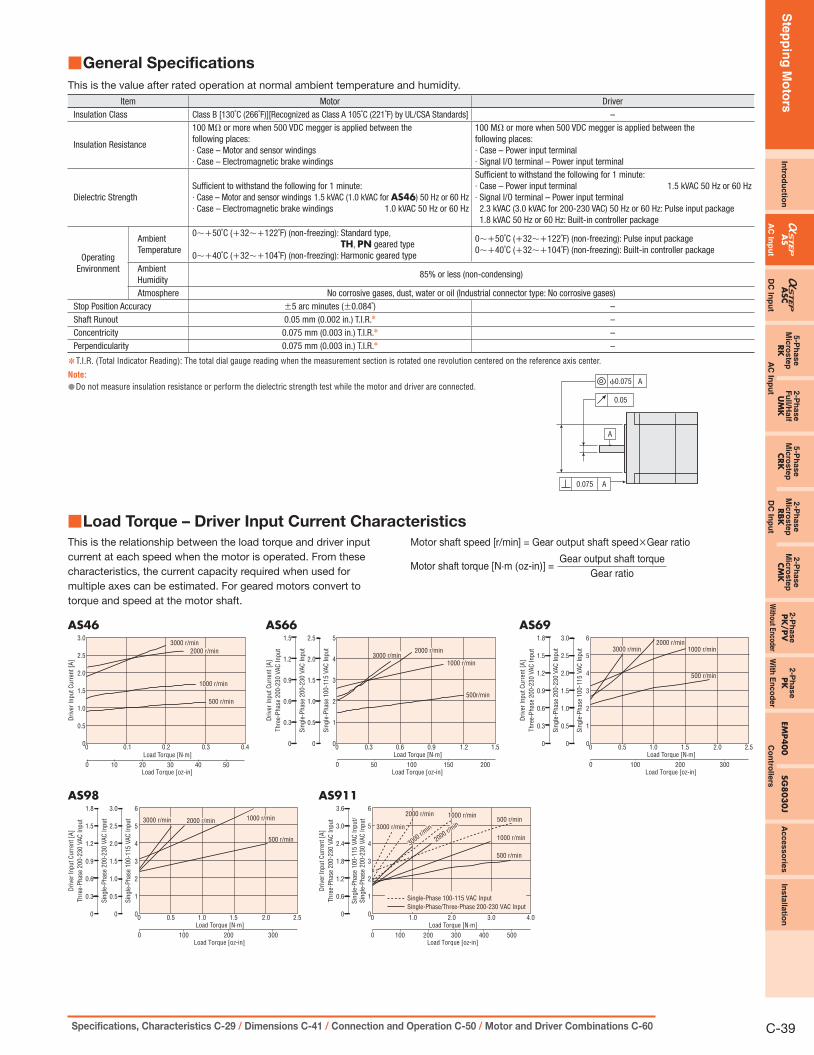
Ste
pp
ing
Mo
tors
Intro
du
ctio
nA
SA
SC5-P
hase
Mic
roste
pRK
2-P
hase
Fu
ll/Half
UM
K
5-P
hase
Mic
roste
pCRK
2-P
hase
Mic
roste
pRBK
2-P
hase
Mic
roste
pCM
K2-P
hase
PK
/PV
2-P
ha
se
PK
EMP40
0SG
803
0J
Accesso
ries
Insta
llatio
n
AC
Inp
ut
DC
Inp
ut
AC
Inp
ut
DC
Inp
ut
Without E
ncoderW
ith E
nc
od
er
Co
ntro
llers
C-39Specifications, Characteristics C-29 / Dimensions C-41 / Connection and Operation C-50 / Motor and Driver Combinations C-60
Load Torque – Driver Input Current Characteristics ■This is the relationship between the load torque and driver input
current at each speed when the motor is operated. From these
characteristics, the current capacity required when used for
multiple axes can be estimated. For geared motors convert to
torque and speed at the motor shaft.
Motor shaft speed [r/min] = Gear output shaft speed×Gear ratio
Motor shaft torque [N·m (oz-in)] =Gear output shaft torque
Gear ratio
General Specifications ■
This is the value after rated operation at normal ambient temperature and humidity.
Item Motor DriverInsulation Class Class B [130˚C (266˚F)][Recognized as Class A 105˚C (221˚F) by UL/CSA Standards] –
Insulation Resistance
100 MΩ or more when 500 VDC megger is applied between the following places:· Case – Motor and sensor windings· Case – Electromagnetic brake windings
100 MΩ or more when 500 VDC megger is applied between the following places:· Case – Power input terminal· Signal I/O terminal – Power input terminal
Dielectric StrengthSufficient to withstand the following for 1 minute:· Case – Motor and sensor windings 1.5 kVAC (1.0 kVAC for AS46) 50 Hz or 60 Hz· Case – Electromagnetic brake windings 1.0 kVAC 50 Hz or 60 Hz
Sufficient to withstand the following for 1 minute:· Case – Power input terminal 1.5 kVAC 50 Hz or 60 Hz· Signal I/O terminal – Power input terminal2.3 kVAC (3.0 kVAC for 200-230 VAC) 50 Hz or 60 Hz: Pulse input package1.8 kVAC 50 Hz or 60 Hz: Built-in controller package
Operating Environment
Ambient Temperature
0∼+50˚C (+32∼+122˚F) (non-freezing): Standard type,TH, PN geared type
0∼+40˚C (+32∼+104˚F) (non-freezing): Harmonic geared type
0∼+50˚C (+32∼+122˚F) (non-freezing): Pulse input package0∼+40˚C (+32∼+104˚F) (non-freezing): Built-in controller package
Ambient Humidity
85% or less (non-condensing)
Atmosphere No corrosive gases, dust, water or oil (Industrial connector type: No corrosive gases)Stop Position Accuracy ±5 arc minutes (±0.084˚) –Shaft Runout 0.05 mm (0.002 in.) T.I.R.✽ –Concentricity 0.075 mm (0.003 in.) T.I.R.✽ –Perpendicularity 0.075 mm (0.003 in.) T.I.R.✽ –
T.I.R. (Total Indicator Reading): The total dial gauge reading when the measurement section is rotated one revolution centered on the reference axis center. ✽
Note:
Do not measure insulation resistance or perform the dielectric strength test while the motor and driver are connected. ●
A
A0.075
Aϕ0.075
0.05
AS46
0.5
1.0
1.5
2.0
2.5
3.0
0.1 0.2 0.3 0.4
3000 r/min
1000 r/min
500 r/min
2000 r/min
Driv
er In
put C
urre
nt [A
]
100 20 30 40 50Load Torque [N·m]
Load Torque [oz-in]
00
AS98
1
2
3
4
5
6
0.5 1.0 1.5 2.0 2.5
0 100 200 300Load Torque [N·m]
Load Torque [oz-in]
00
Driv
er In
put C
urre
nt [A
]
Sing
le-P
hase
100
-115
VAC
Inpu
t
0
0.5
1.0
1.5
2.0
3.0
Sing
le-P
hase
200
-230
VAC
Inpu
t
0
0.3
0.6
0.9
1.2
2.51.5
1.8
Thre
e-Ph
ase
200-
230
VAC
Inpu
t 3000 r/min 1000 r/min
500 r/min
2000 r/min
AS66
1
2
3
4
5
0.3 0.6 0.9 1.2 1.5
500 100 150 200Load Torque [N·m]
Load Torque [oz-in]
00
Driv
er In
put C
urre
nt [A
]
Sing
le-P
hase
100
-115
VAC
Inpu
t
0
0.5
1.0
1.5
2.0
2.5
Sing
le-P
hase
200
-230
VAC
Inpu
t
0
0.3
0.6
0.9
1.2
1.5
Thre
e-Ph
ase
200-
230
VAC
Inpu
t
3000 r/min1000 r/min
500r/min
2000 r/min
AS69
1
2
3
4
5
6
0.5 1.0 1.5 2.0 2.5
0 100 200 300Load Torque [N·m]
Load Torque [oz-in]
00
Driv
er In
put C
urre
nt [A
]
Sing
le-P
hase
100
-115
VAC
Inpu
t
0
0.5
1.0
1.5
2.0
3.0
Sing
le-P
hase
200
-230
VAC
Inpu
t
0
0.3
0.6
0.9
1.2
2.51.5
1.8
Thre
e-Ph
ase
200-
230
VAC
Inpu
t 3000 r/min 1000 r/min
500 r/min
2000 r/min
AS911
1
2
3
4
5
6
1.0 2.0 3.0 4.0
1000 200 300 400 500Load Torque [N·m]
Load Torque [oz-in]
00
Driv
er In
put C
urre
nt [A
]
Sing
le-P
hase
200
-230
VAC
Inpu
tSi
ngle
-Pha
se 1
00-1
15 V
AC In
put/
0
0.6
1.2
1.8
2.4
3.0
3.6
Thre
e-Ph
ase
200-
230
VAC
Inpu
t
Single-Phase 100-115 VAC InputSingle-Phase/Three-Phase 200-230 VAC Input
3000 r/min
3000 r/min
1000 r/min
1000 r/min
500 r/min
500 r/min2000 r/min
2000 r/min
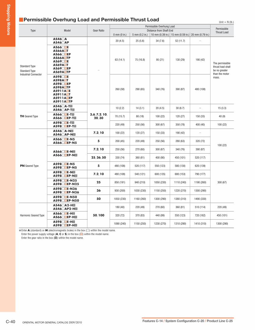
Ste
pp
ing
Mo
tors
C-40 ORIENTAL MOTOR GENERAL CATALOG 2009/2010 Features C-14 / System Configuration C-20 / Product Line C-25
Permissible Overhung Load and Permissible Thrust Load ■ Unit = N (lb.)
Type Model Gear RatioPermissible Overhung Load
PermissibleThrust Load
Distance from Shaft End0 mm (0 in.) 5 mm (0.2 in.) 10 mm (0.39 in.) 15 mm (0.59 in.) 20 mm (0.79 in.)
Standard Type
Standard TypeIndustrial Connector
AS46□AAS46□AP
−
20 (4.5) 25 (5.6) 34 (7.6) 52 (11.7) −
The permissible thrust load shall be no greater than the motor mass.
AS66□■■EAS66A■■TAS66□■■EPAS66A■■TPAS69□■■EAS69A■■TAS69□■■EPAS69A■■TP
63 (14.1) 75 (16.8) 95 (21) 130 (29) 190 (42)
AS98□■■EAS98A■■TAS98□■■EPAS98A■■TPAS911A■■EAS911A■■TAS911A■■EPAS911A■■TP
260 (58) 290 (65) 340 (76) 390 (87) 480 (108)
TH Geared Type
AS46□A-T■■
AS46□AP-T■■
3.6, 7.2, 10, 20, 30
10 (2.2) 14 (3.1) 20 (4.5) 30 (6.7) − 15 (3.3)
AS66□■■E-T■■
AS66□■■EP-T■■70 (15.7) 80 (18) 100 (22) 120 (27) 150 (33) 40 (9)
AS98□■■E-T■■
AS98□■■EP-T■■220 (49) 250 (56) 300 (67) 350 (78) 400 (40) 100 (22)
PN Geared Type
AS46□A-N■■
AS46□AP-N■■7.2, 10 100 (22) 120 (27) 150 (33) 190 (42) −
100 (22)
AS66□■■E-N5AS66□■■EP-N5 5 200 (45) 220 (49) 250 (56) 280 (63) 320 (72)
AS66□■■E-N■■
AS66□■■EP-N■■
7.2, 10 250 (56) 270 (60) 300 (67) 340 (76) 390 (87)
25, 36, 50 330 (74) 360 (81) 400 (90) 450 (101) 520 (117)
AS98□■■E-N5AS98□■■EP-N5 5 480 (108) 520 (117) 550 (123) 580 (130) 620 (139)
300 (67)
AS98□■■E-N■■
AS98□■■EP-N■■7.2, 10 480 (108) 540 (121) 600 (135) 680 (153) 790 (177)
AS98□■■E-N25AS98□■■EP-N25 25 850 (191) 940 (210) 1050 (230) 1110 (240) 1190 (260)
AS98□■■E-N36AS98□■■EP-N36 36 930 (200) 1030 (230) 1150 (250) 1220 (270) 1300 (290)
AS98□■■E-N50AS98□■■EP-N50 50 1050 (230) 1160 (260) 1300 (290) 1380 (310) 1490 (330)
Harmonic Geared Type
AS46□A2-H■■
AS46□AP2-H■■
50, 100
180 (40) 220 (49) 270 (60) 360 (81) 510 (114) 220 (49)
AS66□■■E-H■■
AS66□■■EP-H■■320 (72) 370 (83) 440 (99) 550 (123) 720 (162) 450 (101)
AS98□■■E-H■■
AS98□■■EP-H■■1090 (240) 1150 (250) 1230 (270) 1310 (290) 1410 (310) 1300 (290)
Enter ● A (standard) or M (electromagnetic brake) in the box (□) within the model name.Enter the power supply voltage (A, C or S) in the box (■□) within the model name.Enter the gear ratio in the box (■□) within the model name.

Ste
pp
ing
Mo
tors
Intro
du
ctio
nA
SA
SC5-P
hase
Mic
roste
pRK
2-P
hase
Fu
ll/Half
UM
K
5-P
hase
Mic
roste
pCRK
2-P
hase
Mic
roste
pRBK
2-P
hase
Mic
roste
pCM
K2-P
hase
PK
/PV
2-P
hase
PK
EMP4
00
SG8
03
0J
Accesso
ries
Insta
llatio
n
AC
Inp
ut
DC
Inp
ut
AC
Inp
ut
DC
Inp
ut
Without E
ncoderW
ith E
nc
od
er
Co
ntro
llers
C-41Specifications, Characteristics C-29 / Dimensions C-41 / Connection and Operation C-50 / Motor and Driver Combinations C-60
Dimensions ■ Unit = mm (in.)
Motor ●Standard Type ◇
□1 □42 mm (□1.65 in.)
Model Motor Model L1 L2Mass
kg (lb.)DXF
AS46AAAS46AAP ASM46AA 64.9
(2.56)–
0.5(1.1)
B192
AS46MAAS46MAP ASM46MA –
94.9(3.74)
0.6(1.32)
B193
15.2 (0.60)
31(1.22)
400 (16)
42( 1
.65)
42 (1.65)
12.5
( 0.4
9)
L2L12 (0.08)
4.5±
0.15
( 0.1
77
±0
.00
6)
15±0.25(0.591±0.010)
20±1
(0.79±0.04)
31±0.2 (1.220±0.0079)
31±
0.2
( 1.2
20
±0
.00
79)
ϕ22
−0.
021
( ϕ0.8
661
−0
.00
08)
0ϕ
5−0.
012
( ϕ0.1
969
−0
.00
05)
0
4×M3×4.5 (0.18) Deep
5557-10R (MOLEX)
Motor Cable ϕ7 (ϕ0.28)
Electromagnetic Brake Leads600 mm (24 in.) AWG26
0
0
□2 □60 mm (□2.36 in.)
Model Motor Model L1 L2Mass
kg (lb.)DXF
AS66A□EAS66A□EP ASM66A□E 63.6
(2.50)–
0.85(1.9)
B406
AS66M□EAS66M□EP ASM66M□E –
98.6(3.88)
1.1(2.4)
B407
AS69A□EAS69A□EP ASM69A□E 94.6
(3.72)–
1.4(3.1)
B408
AS69M□EAS69M□EP ASM69M□E –
129.6(5.1)
1.65(3.6)
B409
Enter the power supply voltage ( ● A, C or S) in the box (□) within the model name.
L1
50±
0.35
( 1.9
69±
0.01
4)60
( 2.3
6)
L2
20.5 (0.81)
31.7(1.25)
60 (2.36)50±0.35
(1.969±0.014)
4×ϕ4.5 (ϕ0.177) Thru
15 ( 0
.59)
5557-10R (MOLEX)
400 (16)
24±1
(0.94±0.04)1.5 (0.06)
20±0.25(0.787±0.010)
7 (0.28)
Motor Cable ϕ7 (ϕ0.28)Protective Earth Terminal M4
7.5±
0.15
( 0.2
95
±0
.00
6)
ϕ8−
0.01
5 ( ϕ
0.3
150
−0
.00
06)
00
ϕ36
−0.
025
( ϕ1.4
173
−0
.00
10)
00

Ste
pp
ing
Mo
tors
C-42 ORIENTAL MOTOR GENERAL CATALOG 2009/2010 Features C-14 / System Configuration C-20 / Product Line C-25
□3 □85 mm (□3.35 in.)
Model Motor Model L1 L2Mass
kg (lb.)DXF
AS98A□EAS98A□EP ASM98A□E 80
(3.15)–
1.8(4.0)
B410
AS98M□EAS98M□EP ASM98M□E –
131(5.16)
2.2(4.8)
B411
AS911A□EAS911A□EP ASM911A□E 110
(4.33)–
3(6.6)
B412
Enter the power supply voltage ( ● A, C or S) in the box (□) within the model name.
4×ϕ6.5 (ϕ0.256) Thru
Motor Cable ϕ7 (ϕ0.28)Protective Earth Terminal M4
2 (0.08)
31.7(1.25) 15
( 0.5
9)
70±0.35(2.756±0.014)
85 ( 3
.35)
85 (3.35)L2
L1
400 (16)20.5 (0.81)
37±1
(1.46±0.04)10 (0.39)
25±0.25(0.984±0.010)
70±
0.35
( 2.7
56
±0
.01
4)
13±
0.15
( 0.5
12
±0
.00
6)
ϕ60
−0.
030
( ϕ2.3
622
−0
.00
12)
0ϕ
14−
0.01
8 ( ϕ
0.5
512
−0
.00
07)
0
5557-10R (MOLEX)
0 0

Ste
pp
ing
Mo
tors
Intro
du
ctio
nA
SA
SC5-P
hase
Mic
roste
pRK
2-P
hase
Fu
ll/Half
UM
K
5-P
hase
Mic
roste
pCRK
2-P
hase
Mic
roste
pRBK
2-P
hase
Mic
roste
pCM
K2-P
hase
PK
/PV
2-P
ha
se
PK
EMP40
0SG
803
0J
Accesso
ries
Insta
llatio
n
AC
Inp
ut
DC
Inp
ut
AC
Inp
ut
DC
Inp
ut
Without E
ncoderW
ith E
nc
od
er
Co
ntro
llers
C-43Specifications, Characteristics C-29 / Dimensions C-41 / Connection and Operation C-50 / Motor and Driver Combinations C-60
Standard Type Industrial Connector ◇
□4 □60 mm (□2.36 in.)
Model Motor Model LMass
kg (lb.)DXF
AS66A□TAS66A□TP ASM66A□T 98.7
(3.89)1
(2.2)B364
AS69A□TAS69A□TP ASM69A□T 129.7
(5.11)1.5
(3.3)B365
Enter the power supply voltage ( ● A, C or S) in the box (□) within the model name.Always use the motor cable for industrial connector type (sold separately) for connection between the industrial connector type motor and the driver. ●
60 (2.36)39(1.54)
10.3 (0.41)
10.3
( 0.4
1)
RC-09P1N122300 (CONINVERS)
2(0.08)
L
70.3
( 2.7
7)
M4
10 (0.39)
60 ( 2
.36)
82.5
( 3.2
5) m
ax.
7 (0.28)4×ϕ4.5 (ϕ0.177) Thru50±0.35
(1.969±0.014)
24±1
(0.94±0.04)
20±0.25(0.787±0.010)
50±
0.35
( 1.9
69±
0.01
4)
Protective Earth Terminal M4 7.5±
0.15
( 0.2
95
±0
.00
6)
ϕ8−
0.01
5 ( ϕ
0.3
150
−0
.00
06)
00
ϕ36
−0.
039
( ϕ1.4
173
−0
.00
15)
00
□5 □85 mm (□3.35 in.)
Model Motor Model LMass
kg (lb.)DXF
AS98A□TAS98A□TP ASM98A□T 110
(4.33)2.2
(4.8)B317
AS911A□TAS911A□TP ASM911A□T 140
(5.51)3.3
(7.3)B318
Enter the power supply voltage ( ● A, C or S) in the box (□) within the model name.Always use the motor cable for industrial connector type (sold separately) for connection between the industrial connector type motor and the driver. ●
85 (3.35)
107
( 4.2
1) m
ax.
10(0.39)
10.3
( 0.4
1)
95.3
( 3.7
5)
10.3 (0.41)M4
2(0.08)
40.6(1.60)
L
85 ( 3
.35)
10 (0.39)
RC-09P1N122300 (CONINVERS)
37±1(1.46±0.04)
25±0.25(0.984±0.010)
70±0.35(2.756±0.014)
70±
0.35
( 2.7
56±
0.01
4)
Protective Earth Terminal M4
4×ϕ6.5 (ϕ0.256) Thru
13±
0.15
( 0.5
12
±0
.00
6)
ϕ60
−0.
030
( ϕ2.3
622
−0
.00
12)
0ϕ
14−
0.01
8 ( ϕ
0.5
512
−0
.00
07)
00 0
●Requirement for Motor Cable for Industrial Connector Type (Sold separately)Always use the motor cable for industrial connector type (sold separately) for connection between the industrial connector type motor and the driver.
The industrial connector type motor cannot be driven unless the dedicated motor cable is used.
Motor Cables for ◇Industrial Connector Type
Flexible Motor Cables for ◇Industrial Connector Type
Model Length: L m (ft.) Model Length: L m (ft.)CC01AST 1 (3.3) CC01SAR2 1 (3.3)
CC02AST 2 (6.6) CC02SAR2 2 (6.6)
CC03AST 3 (9.8) CC03SAR2 3 (9.8)
CC05AST 5 (16.4) CC05SAR2 5 (16.4)
CC07AST 7 (23) CC07SAR2 7 (23)
CC10AST 10 (32.8) CC10SAR2 10 (32.8)
CC15AST 15 (49.2)
CC20AST 20 (65.6)
Motor Cables/Flexible Motor Cables for Industrial Connector Type
L
CC__AST: ϕ8 (ϕ0.31)CC__SAR2: ϕ9.5 (ϕ0.37)
CC__AST: RC-09S1N1280S1 (CONINVERS)CC__SAR2: RC-09S1N1280U1 (CONINVERS)
Motor SideDriver Side
5557-10R (MOLEX)
14.5 (0.57)
22.2
( 0.8
7)
19.6(0.77)
51.1 (2.01)26
(1.02)
11.6 (0.46)

Ste
pp
ing
Mo
tors
C-44 ORIENTAL MOTOR GENERAL CATALOG 2009/2010 Features C-14 / System Configuration C-20 / Product Line C-25
TH ◇ Geared Type
□6 □42 mm (□1.65 in.)
Model Motor Model Gear Ratio L1 L2Mass
kg (lb.)DXF
AS46AA-T■□
AS46AAP-T■□ASM46AA-T■□
3.6, 7.2, 10, 20, 30
95.4(3.76)
–0.65
(1.43)B199
AS46MA-T■□
AS46MAP-T■□ASM46MA-T■□ –
125.4(4.94)
0.75(1.7)
B200
Enter the gear ratio in the box ( ● ■□) within the model name.
L142 (1.65)
42 ( 1
.65)
12.5
( 0.4
9)
31(1.22)
L2
Electromagnetic Brake Leads600 mm (24 in.) AWG26
5557-10R (MOLEX)
15.2 (0.60)
Motor Cable ϕ7 (ϕ0.28)
400 (16)
ϕ6−
0.01
2 ( ϕ
0.2
362
−0
.00
05)
00
ϕ17
−0.
018
( ϕ0.6
693
−0
.00
07)
00
5.5±
0.15
( 0.2
17
±0
.00
6)
20±1 (0.79±0.04)3.5 (0.14)12 (0.47)
8±0.
5 ( 0
.31
±0
.02)
4×M4×8 (0.31) Deep
43.8±0.5
(1.72±0.0
2)
□7 □60 mm (□2.36 in.)
Model Motor Model Gear Ratio L1 L2Mass
kg (lb.)DXF
AS66A□E-T■□
AS66A□EP-T■□ASM66A□E-T■□
3.6, 7.2, 10, 20, 30
108.6(4.28)
–1.25(2.8)
B413
AS66M□E-T■□
AS66M□EP-T■□ASM66M□E-T■□ –
143.6(5.65)
1.5(3.3)
B414
Enter the power supply voltage ( ● A, C or S) in the box (□) within the model name.Enter the gear ratio in the box (■□) within the model name.
60 ( 2
.36)
60 (2.36)
15 ( 0
.59)
L2L1
20.5 (0.81)
31.7(1.25)
12 (0.47)3.5 (0.14)
Motor Cable ϕ7 (ϕ0.28)Protective Earth Terminal M4
4×M4×8 (0.31) Deep
5557-10R (MOLEX)
400 (16)
ϕ8−
0.01
5 ( ϕ
0.3
150
−0
.00
06)
00
ϕ23
−0.
021
( ϕ0.9
055
−0
.00
08)
00
7±0.
15 ( 0
.276
±0.
006)
10±
0.5
( 0.3
9±0.
02)
32±1
(1.26±0.04)
70±
0.5
(2.76
±0.
02)

Ste
pp
ing
Mo
tors
Intro
du
ctio
nA
SA
SC5-P
hase
Mic
roste
pRK
2-P
hase
Fu
ll/Half
UM
K
5-P
hase
Mic
roste
pCRK
2-P
hase
Mic
roste
pRBK
2-P
hase
Mic
roste
pCM
K2-P
hase
PK
/PV
2-P
ha
se
PK
EMP40
0SG
803
0J
Accesso
ries
Insta
llatio
n
AC
Inp
ut
DC
Inp
ut
AC
Inp
ut
DC
Inp
ut
Without E
ncoderW
ith E
nc
od
er
Co
ntro
llers
C-45Specifications, Characteristics C-29 / Dimensions C-41 / Connection and Operation C-50 / Motor and Driver Combinations C-60
□8 □90 mm (□3.54 in.)
Model Motor Model Gear Ratio L1 L2Mass
kg (lb.)DXF
AS98A□E-T■□
AS98A□EP-T■□ASM98A□E-T■□
3.6, 7.2, 10, 20, 30
144.5(5.69)
–3
(6.6)B415
AS98M□E-T■□
AS98M□EP-T■□ASM98M□E-T■□ –
195.5(7.70)
3.4(7.5)
B416
Enter the power supply voltage ( ● A, C or S) in the box (□) within the model name.Enter the gear ratio in the box (■□) within the model name.
A
A
90 (3.54)
L2
90 ( 3
.54)
31.7(1.25)
L1
85 ( 3
.35)
15 ( 0
.59)
85 (3.35)
400 (16)
5557-10R (MOLEX)
+0.
1Motor Cable ϕ7 (ϕ0.28)
Protective Earth Terminal M4
20.5 (0.81)
ϕ12
−0.
018
( ϕ0.4
724
−0
.00
07)
00
ϕ35
−0.
025
( ϕ1.3
780
−0
.00
10)
00
4−0.
03 ( 0
.1575
−0
.00
12)
00
2.5
0 ( 0
.098
0
)
18±
0.5
( 0.7
1±0.
02)
32±1
(1.26±0.04)3.5(0.14)
25(0.98)
4×M8×15 (0.59) Deep
104±0.5
(4.09±0.0
2)
25±0.2(0.984±0.008)
+0
.00
4
Parallel Key (Included)
4−0.03
(0.1575−0.0012)
0
0
4−0.03
(0.1575−0.0012)
0
0
A – A
◇PN Geared Type
□9 □42 mm (□1.65 in.)
Model Motor Model Gear Ratio L1 L2Mass
kg (lb.)DXF
AS46AA-N■□
AS46AAP-N■□ASM46AA-N■□
7.2, 10
96.9(3.18)
–0.71(1.6)
B306
AS46MA-N■□
AS46MAP-N■□ASM46MA-N■□ –
126.9(5.0)
0.81(1.8)
B307
Enter the gear ratio in the box ( ● ■□) within the model name.
A
A
400 (16)
42 ( 1
.65)
31(1.22)
L1L2
5557-10R (MOLEX)
3−0.029 (0.1181−0.0011) −0.004
1.8
0
( 0.0
71
0
)
+0.
1
Parallel Key (Included)
Electromagnetic Brake Leads600 mm (24 in.) AWG26
Motor Cable ϕ7 (ϕ0.28)
15.2 (0.60)
18 (0.71)6 (0.24)
ϕ10
−0.
015
( ϕ0.3
937
−0
.00
06)
00
ϕ37
.6−
0.02
5 ( ϕ
1.4
803
−0
.00
10)
00
3−0.
025
( 0.1
181
−0
.00
10)
00
3−0.025
(0.1181−0.0010)0
0
25±1
(0.98±0.04)
42 (1.65)4×M4×8 (0.31) Deep
12.5
( 0.4
9)
18±0.2
(0.7087±0.0079)
−0.0002
+0
.00
4
48±0.3
(1.890±0.0
12)
A – A

Ste
pp
ing
Mo
tors
C-46 ORIENTAL MOTOR GENERAL CATALOG 2009/2010 Features C-14 / System Configuration C-20 / Product Line C-25
□10 □60 mm (□2.36 in.)
Model Motor Model Gear Ratio L1 L2Mass
kg (lb.)DXF
AS66A□E-N■□
AS66A□EP-N■□ASM66A□E-N■□
5, 7.2, 10 107.6(4.24)
–1.5
(3.3)B425
25, 36, 50 123.6(4.87)
–1.7
(3.7)B426
AS66M□E-N■□
AS66M□EP-N■□ASM66M□E-N■□
5, 7.2, 10 –142.6(5.61)
1.75(3.9)
B427
25, 36, 50 –158.6(6.24)
1.95(4.3)
B428
Enter the power supply voltage ( ● A, C or S) in the box (□) within the model name.Enter the gear ratio in the box (■□) within the model name.
L2
25±0.2
(0.984±0.008)
70±0.5
(2.76±0.0
2)
60 ( 2
.36)
60 (2.36)
400 (16)20.5 (0.81)
6 (0.24)L1
25(0.98)
5557-10R (MOLEX)Motor Cable ϕ7 (ϕ0.28)
Protective Earth Terminal M4
A
A
38±1
(1.50±0.04)
ϕ12
−0.
018
( ϕ0.4
724
−0
.00
07)
00
ϕ37
−0.
025
( ϕ1.4
567
−0
.00
10)
00
4×M5×10 (0.39) Deep
15 ( 0
.59)
31.7(1.25)
4−0.
03 ( 0
.1575
−0
.00
12)
00
4−0.03
(0.1575−0.0012)
0
0
4−0.03
(0.1575−0.0012)
0
0
+0.
12.
5 0
( 0.0
98
0
)
+0
.00
4
Parallel Key (Included) A – A
□11 □90 mm (□3.54 in.)
Model Motor Model Gear Ratio L1 L2Mass
kg (lb.)DXF
AS98A□E-N■□
AS98A□EP-N■□ASM98A□E-N■□
5, 7.2, 10 140(5.51)
–4
(8.8)B429
25, 36, 50 163(6.42)
–4.7(10)
B430
AS98M□E-N■□
AS98M□EP-N■□ASM98M□E-N■□
5, 7.2, 10 –191
(7.52)4.4
(9.7)B431
25, 36, 50 –214
(8.43)5.1(11)
B432
Enter the power supply voltage ( ● A, C or S) in the box (□) within the model name.Enter the gear ratio in the box (■□) within the model name.
A
A85 ( 3
.35)
L2
85 (3.35) 90 (3.54)
90 ( 3
.54)
L1
20.5 (0.81)400 (16)
31.7(1.25)
15( 0
.59)
25(0.98)
6 (0.24)
104±0.5
(4.09±0.0
2)
47±1(1.85±0.04)
5557-10R (MOLEX)Motor Cable ϕ7 (ϕ0.28)
Protective Earth Terminal M4
25±0.2(0.984±0.008)
Parallel Key (Included)
6−0.03 0
0
6−0.03 0 3.
5
0
( 0.1
38
+0
.00
4)
+0.
1
4×M8×15 (0.59) Deep
ϕ18
−0.
018
( ϕ0.7
087
−0
.00
07)
00
ϕ61
−0.
030
( ϕ2.4
016
−0
.00
12)
00
0
(0.2362−0.0012)0 (0.2362−0.0012)0
6−0.
03
( 0.2
362
−0
.00
12)
0
A – A
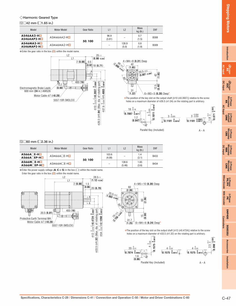
Ste
pp
ing
Mo
tors
Intro
du
ctio
nA
SA
SC5-P
hase
Mic
roste
pRK
2-P
hase
Fu
ll/Half
UM
K
5-P
hase
Mic
roste
pCRK
2-P
hase
Mic
roste
pRBK
2-P
hase
Mic
roste
pCM
K2-P
hase
PK
/PV
2-P
hase
PK
EMP4
00
SG8
03
0J
Accesso
ries
Insta
llatio
n
AC
Inp
ut
DC
Inp
ut
AC
Inp
ut
DC
Inp
ut
Without E
ncoderW
ith E
nc
od
er
Co
ntro
llers
C-47Specifications, Characteristics C-29 / Dimensions C-41 / Connection and Operation C-50 / Motor and Driver Combinations C-60
Harmonic Geared Type ◇
□12 □42 mm (□1.65 in.)
Model Motor Model Gear Ratio L1 L2Mass
kg (lb.)DXF
AS46AA2-H■□
AS46AAP2-H■□ASM46AA2-H■□
50, 100
96.9(3.81)
–0.7
(1.5)B308
AS46MA2-H■□
AS46MAP2-H■□ASM46MA2-H■□ –
126.9(5.0)
0.8(1.8)
B309
Enter the gear ratio in the box ( ● ■□) within the model name.
✽The position of the key slot on the output shaft [ϕ10 (ϕ0.3937)] relative to the screw holes on a maximum diameter of ϕ26.5 (ϕ1.04) on the rotating part is arbitrary.
A
A
42(1.65)
42( 1
.65)
12.5
( 0.4
9)
31(1.22)
15.2(0.60)
L1L2
18 (0.71)
400 (16)
0.5(0.02)
2 (0.08)
1.2(0.047)
20.5±0.2
(0.807±0.008)
48±0.3(1.890±
0.012)
4×M4×8 (0.31) Deep
6×M3×5 (0.20) Deep✽
25±1(0.98±0.04)
60˚
ϕ26
.5 (ϕ
1.0
4) (
Max
. dia
. of r
otat
ing
part)
3−0.
025
( 0.1
811
−0
.00
10)
0
3−0.025 0
90˚
3−0.029 −0.004
Parallel Key (Included)
Electromagnetic Brake Leads600 mm (24 in.) AWG26
Motor Cable ϕ7 (ϕ0.28)
ϕ37
.6−
0.02
5 ( ϕ
1.4
803
−0
.00
10)
00
ϕ10
−0.
015
( ϕ0.3
937
−0
.00
06)
00
(0.1181−0.0010)0 (0.1181−0.0011)−0.0002 1.8
0
( 0.0
71
+0
.00
4)
+0.
1
0
18−0.18
(0.7087−0.0071)
0
0
5557-10R (MOLEX)
0
A – A
□13 □60 mm (□2.36 in.)
Model Motor Model Gear Ratio L1 L2Mass
kg (lb.)DXF
AS66A□E-H■□
AS66A□EP-H■□ASM66A□E-H■□
50, 100
103.6(4.08)
–1.4
(3.1)B433
AS66M□E-H■□
AS66M□EP-H■□ASM66M□E-H■□ –
138.6(5.46)
1.65(3.6)
B434
Enter the power supply voltage ( ● A, C or S) in the box (□) within the model name.Enter the gear ratio in the box (■□) within the model name.
L1L2
31.7(1.25)
15( 0
.59)
60˚
60( 2
.36)
60(2.36)
400 (16)20.5 (0.81)
1.5(0.06) 20 (0.79)
A
A
2 (0.08)
ϕ33
.5 (ϕ
1.3
2) (
Max
. dia
. of r
otat
ing
part)
ϕ54
−0.
03 ( ϕ
2.1
260
−0
.00
12)
00
ϕ12
−0.
018
( ϕ0.4
724
−0
.00
07)
00
90˚
70±
0.5
(2.75
6±0.
020)
6×M4×6 (0.24) Deep✽
28.5±1(1.12±0.04)
Protective Earth Terminal M4Motor Cable ϕ7 (ϕ0.28)
5557-10R (MOLEX)
Parallel Key (Included)
✽The position of the key slot on the output shaft [ϕ12 (ϕ0.4724)] relative to the screw holes on a maximum diameter of ϕ33.5 (ϕ1.32) on the rotating part is arbitrary.
4×M5×10 (0.39) Deep
25.5±0.2(1.003±0.008)
1.6(0.06)
20−0.21
(0.7874−0.0083) 0
0
4−0.03
(0.1575−0.0012) 0
0
4−0.03
(0.1575−0.0012) 0
0
4−0.
03
( 0.1
575
−0
.00
12)
0
0
2.5
0
( 0.0
98
+0
.00
4)
+0.
1
0
A – A

Ste
pp
ing
Mo
tors
C-48 ORIENTAL MOTOR GENERAL CATALOG 2009/2010 Features C-14 / System Configuration C-20 / Product Line C-25
□14 □90 mm (□3.54 in.)
Model Motor Model Gear Ratio L1 L2Mass
kg (lb.)DXF
AS98A□E-H■□
AS98A□EP-H■□ASM98A□E-H■□
50, 100
163.5(6.44)
–3.9
(8.6)B435
AS98M□E-H■□
AS98M□EP-H■□ASM98M□E-H■□ –
214.5(8.44)
4.3(9.5)
B436
Enter the power supply voltage ( ● A, C or S) in the box (□) within the model name.
Enter the gear ratio in the box (■□) within the model name.
A
A
L1L2
85 ( 3
.35)
85 (3.35)
90 ( 3
.54)
90 (3.54)
20.5(0.81)400 (16)
31.7(1.25) 15
( 0.5
9)
15 (0.59)
28(1.10)
25(0.98)
3 (0.12) 3.5(0.14)
4×ϕ9.2 (ϕ0.362) Thru
104±0.5
ϕ50
(ϕ1.9
7)
ϕ22
(ϕ0.8
7)
ϕ18
−0.
018
( ϕ0.7
087
−0
.00
07)
0
40±1.2
Protective Earth Terminal M4Motor Cable ϕ7 (ϕ0.28)
5557-10R (MOLEX)
2.4(0.09)
25−0.21 0
90˚
6−0.03 0
6−0.03 0 3.
5
0 +
0.1
Parallel Key (Included)
(1.57±0.05) 0
0
ϕ83
−0.
035
( ϕ3.2
677
−0
.00
14)
00
(4.09±0.0
2)
(0.9843−0.0083)0(0.2362−0.0012) 0(0.2362−0.0012)
00
6−0.
03 ( 0
.2362
−0
.00
12)
( 1.1
38
0
)
+0.0
04
A – A
Electromagnetic brake models except frame size ● □42 mm (□1.65 in.) must use an extension cable or flexible extension cable for the
electromagnetic brake motor.
Extension cables for electromagnetic brake motor ➜ Page C-297
Extension Cables for Electromagnetic Brake Motor ●
Driver SideMotor SideElectromagnetic Brake Leads 60 mm (2.4 in.) (Orange/Black, Gray AWG24)
L12 (0.47)
30( 1
.18)
24.3
( 0.9
6)
ϕ8 (ϕ0.31)
22.2
( 0.8
7)
14.5 (0.57)11.6 (0.46)
Model Length: L m (ft.)CC01AIPM 1 (3.3)CC02AIPM 2 (6.6)CC03AIPM 3 (9.8)CC05AIPM 5 (16.4)CC07AIPM 7 (23)CC10AIPM 10 (32.8)CC15AIPM 15 (49.2)CC20AIPM 20 (65.6)
Flexible Extension Cables for Electromagnetic Brake Motor ●
L
Motor Side Driver SideElectromagnetic Brake Leads 60 mm (2.4 in.) (Orange, Gray AWG24)
12 (0.47)
30( 1
.18)
24.3
( 0.9
6)
14.5 (0.57)11.6 (0.46)
ϕ9.5 (ϕ0.37)
22.2
( 0.8
7)
Model Length: L m (ft.)CC01SARM2 1 (3.3)CC02SARM2 2 (6.6)CC03SARM2 3 (9.8)CC05SARM2 5 (16.4)CC07SARM2 7 (23)CC10SARM2 10 (32.8)

Ste
pp
ing
Mo
tors
Intro
du
ctio
nA
SA
SC5-P
hase
Mic
roste
pRK
2-P
hase
Fu
ll/Half
UM
K
5-P
hase
Mic
roste
pCRK
2-P
hase
Mic
roste
pRBK
2-P
hase
Mic
roste
pCM
K2-P
hase
PK
/PV
2-P
hase
PK
EMP4
00
SG8
03
0J
Accesso
ries
Insta
llatio
n
AC
Inp
ut
DC
Inp
ut
AC
Inp
ut
DC
Inp
ut
Without E
ncoderW
ith E
nc
od
er
Co
ntro
llers
C-49Specifications, Characteristics C-29 / Dimensions C-41 / Connection and Operation C-50 / Motor and Driver Combinations C-60
Driver ●□15 Pulse Input PackageASD13□-A, ASD24□-A, ASD30□-AASD12□-C, ASD16□-C, ASD20A-CASD12□-S, ASD16□-S, ASD20A-SMass: 0.8 kg (1.8 lb.)
B197
Mounting Bracket ●(2 pieces, included)
45 (1.77)
25 (0.98)
25(0.98)
2×ϕ3.5 (ϕ0.138) Countersink
10 ( 0
.39
)10
( 0.3
9)
4.5(0.177)
3 (0.12)
43 ( 1
.69
)
Control I/O Connector (Included) ●Cover Assembly: 54331-1361 (MOLEX)Connector: 54306-3619 (MOLEX)
Control I/O Connector (Included) ●Cover Assembly: 54331-1361 (MOLEX)Connector: 54306-3619 (MOLEX)
Sensor Input Connector (Included) ●Cover Assembly: 54331-1201 (MOLEX)Connector: 54306-2019 (MOLEX)
M4
17( 0
.67
)
6.32
( 0.2
4)
5 (0.20)max.
3×M3
7.62
( 0.3
0)
120 (4.72) 41 (1.61)max.
11 (0.43)
6 ( 0
.24
)13
4 ( 5
.28
)10
( 0.3
9)
7×M3
23(0.91)
9 (0.35)9 (0.35)
45 (1.77)
25(0.98)
10 (0.39)
150
( 5.9
1)
180
( 7.0
9)
200
( 7.8
7)
89 ( 3
.50)
25( 0
.98
)
3(0.12)
□16 Built-In Controller PackageASD13□-AP, ASD24□-AP, ASD30□-APASD12□-CP, ASD16□-CP, ASD20A-CPASD12□-SP, ASD16□-SP, ASD20A-SPMass: 0.8 kg (1.8 lb.)
B298
11 (0.43)
3(0.12)
120 (4.72) 41 (1.61)max.
6.32
( 0.2
4)
7.62
( 0.3
0)
5 (0.20)max.
150
( 5.9
1)
45 (1.77)
25(0.98)
10 (0.39)
180
( 7.0
9)
200
( 7.8
7)
6 ( 0
.24
)13
4 ( 5
.28
)10
( 0.3
9)
7×M3
23(0.91)
9 (0.35)9 (0.35)
M4
17( 0
.67
)
3×M3
89 ( 3
.50
)25
( 0.9
8)
Mounting Bracket ●(2 pieces, included)
45 (1.77)
25 (0.98)
25(0.98)
2×ϕ3.5 (ϕ0.138) Countersink
10 ( 0
.39
)10
( 0.3
9)
4.5(0.177)
3 (0.12)
43 ( 1
.69
)

Ste
pp
ing
Mo
tors
C-50 ORIENTAL MOTOR GENERAL CATALOG 2009/2010 Features C-14 / System Configuration C-20 / Product Line C-25
Connection and Operation (Pulse Input Package) ■
Names and Functions of Driver Parts ●
Motor Connector
Not used.
Power Input Terminals
Protective EarthTerminal
□1
□2
□3
□4
□5
□1 Signal Monitor Display
LED Indicators ◇Indication Color Function When Activated
OPERATION Green Power Supply Indication Lights when power is on.ALARM Red Alarm Indication Blinks when protective functions are activated.
Alarm ◇Blink Count Function When Activated
1 Overheat The temperature of the driver's internal heat sink has reached approximately 85˚C (185˚F).2 Overload The motor has been operated continuously over 5 seconds under a load exceeding the maximum torque.3 Overvoltage The primary voltage of the driver's inverter has exceeded the allowable level.4 Speed Error The motor cannot accurately follow at the indicated pulse speed.5 Overcurrent An excessive current has flowed through the inverter power element inside the driver.6 Overspeed The motor shaft velocity exceeds 5000 r/min. (Except geared type)7 EEPROM Data Error A motor control parameter has been damaged.8 Sensor Error The power has been turned on without the motor cable connected to the driver.
Lights(No blinking)
System Error The driver has fatal error.
□2 Function SwitchesIndication Switch Name Function
1000/500×1/×10
Resolution Select Switch
This function is for selecting the motor resolution. For each geared type, the resolution of gear output shaft is 1/gear ratio.[1000] [×1] ➝ 1000 P/R (0.36˚/step)[1000] [×10] ➝ 10000 P/R (0.036˚/step)[500] [×1] ➝ 500 P/R (0.72˚/step)[500] [×10] ➝ 5000 P/R (0.072˚/step)
1P/2P Pulse Input Mode SwitchThe settings of this switch are compatible with the following two types of pulse input modes:"1P" for the 1-pulse input mode, "2P" for the 2-pulse input mode.
Notes:
Always turn the power off before switching resolution or pulse input, and turn it ON again after you have made the change. ●If the resolution select switch is set to [ ● ×10], it cannot control the resolution selected by the input signal. It is always [×10].
□3 Current Adjustment SwitchIndication Switch Name Function
CURRENT Current Adjustment SwitchThe motor running current can be lowered to suppress temperature rise in the motor and driver, or lower operating current in order to allow a margin for motor torque (a maximum of 16 settings).
□4 Velocity Filter Adjustment SwitchIndication Switch Name Function
V.FILVelocity Filter Adjustment
Switch
This switch is used to make adjustments when a smooth start-stop or smooth motion at low speed is required (a maximum of 16 settings).
Time
Mot
or S
peed
Set to "0"
Set to "F"
· The differencein characteristicsmode by thevelocity filter.
□5 Input/Output Signals (36 pins)Indication Input/Output Pin. No Signal Signal Name
CN4
External power input
1 Vcc+5VPower Supply for Signal Control
2 GND3 Vcc+24V
Input
9 DIR. (CCW) Rotation Direction(CCW Pulse)✽10 DIR. (CCW)
11 PLS (CW) Pulse(CW Pulse)✽12 PLS (CW)
Output
13 BSG1 Quadrature BSG Output(Open-collector)14 GND
15 ASG1 Quadrature ASG Output(Open-collector)16 GND
17 BSG2 Quadrature BSG Output(Line driver)18 BSG2
19 ASG2 Quadrature ASG Output(Line driver)20 ASG2
Input21 ACL
Alarm Clear22 ACL
Output
23 TIM.1 Timing (Open-collector)24 GND
25 ALARMAlarm
26 ALARM27 TIM.2 Timing
(Line driver)28 TIM.229 END Positioning
Completion30 END
Input
31 ×10Resolution Select
32 ×1033 C.OFF
All Windings Off34 C.OFF
Description of input/output signals ➜ Page C-52 Signal name in parentheses represents the setting in 2-pulse ✽
input mode.

Ste
pp
ing
Mo
tors
Intro
du
ctio
nA
SA
SC5-P
hase
Mic
roste
pRK
2-P
hase
Fu
ll/Half
UM
K
5-P
hase
Mic
roste
pCRK
2-P
hase
Mic
roste
pRBK
2-P
hase
Mic
roste
pCM
K2-P
hase
PK
/PV
2-P
ha
se
PK
EMP40
0SG
803
0J
Accesso
ries
Ins
talla
tion
AC
Inp
ut
DC
Inp
ut
AC
Inp
ut
DC
Inp
ut
Without E
ncoderW
ith E
nc
od
er
Co
ntro
llers
C-51Specifications, Characteristics C-29 / Dimensions C-41 / Connection and Operation C-50 / Motor and Driver Combinations C-60
Connection Diagram ●
Pulse Signal (CW Pulse Signal)
Rotation Direction Signal (CCW Pulse Signal)
All Windings Off Signal
PositioningCompletion Signal
Timing Signal
Alarm Signal
ConnectorCN2
TerminalBlock
Power Supply VoltageSingle-Phase 100-115 VAC −15%∼+10% 50/60 Hz(For single-phase 100-115 VAC input driver)Single-Phase 200-230 VAC −15%∼+10% 50/60 Hz(For single-phase 200-230 VAC input driver)Three-Phase 200-230 VAC −15%∼+10% 50/60 Hz(For three-phase 200-230 VAC input driver)
(Pin No.)Twisted-Pair Wire
Counter,Tachometeretc.
Vcc5VVcc24V
L
N
(L1)
(L2)
(L3)
CN4
Protective Earth (PE)(Use wire of AWG18 or thicker.)
Terminal Block
L
N
Terminal Block
L1
L2
L3
Single-Phase 100-115 VAC,Single-Phase 200-230 VAC
Three-Phase200-230 VAC
InputSignals
OutputSignals
R2
11
12
0 V
0 V
R2
R2
Driver
0 V
R1
R1
BSG1GND
GNDASG1
BSG2
ASG2
GND
9
10
34
29
3025
2623
24
1315161314
192017182
V0 (+30 VDC max.)
A suitable controller for AS Series is available.Controller EMP400 Series ➜ Page C-274Driver cables ➜ Page C-300
Alarm Clear SignalR1
Resolution Select Signal
R1
R1
33
21
2231
32
Controller
V0 MotorProtective Earth (PE)(Use wire of AWG18 or thicker.)
Caution
■Connecting the Electromagnetic Brake to a Power SupplyConnect the electromagnetic brake to the power supply using a cable of at least AWG24. The power supply input to the electromagnetic brake is 24 VDC ±5% 0.3 A minimum (AS46: 0.1 A minimum) and therefore must be independent of the driver's power supply for signal control.Notes:
Applying a voltage that exceeds the specifications will cause the electromagnetic brake to ●generate a great amount of heat, resulting in motor temperature rises and possible damage to the motor. Conversely, if voltage is too low, the electromagnetic brake may not release.To protect the switch contacts and prevent noise, always connect the surge suppressor. ● ✽
(✽The surge suppressor is included with electromagnetic brake motors.)To prevent noise, use a dedicated power supply for electromagnetic brake. ●Correct polarity ( ● + and −) must be ensured when connecting the electromagnetic brake leads of AS Series to the DC power supply. If polarity is incorrect, the electromagnetic brake will not operate. When using as a CE certified part, use a dedicated DC power supply for electromagnetic brake. ●
(1) AS46The electromagnetic brake leads are linked to the connector on the motor [600 mm (23.6 in.)]. When connecting with the DC power supply, connect the red spiral lead wire to +24 V, and the black lead wire to the ground (GND). Use the extension cable or the flexible extension cable (both sold separately).
24 VDC
SurgeSuppressor✽
Switch
+ −Motor
AS Series Driver
Black
Red
Extension Cable(Sold separately)
(2) AS66, AS69, AS98The electromagnetic brake leads are linked to the connector on the driver connection side of extension cable for electromagnetic brake motor (sold separately). Be sure to use the accessory (sold separately) extension cable or flexible extension cable. Connect the orange/black spiral lead wire (orange for flexible extension cable)[60 mm (2.36 in.)] to +24 V, and the gray lead wire [60 mm (2.36 in.)] to the ground (GND).
Motor
AS Series Driver
Extension Cable forElectromagnetic
Brake Motor(Sold separately)
24 VDC
SurgeSuppressor✽
SwitchOrange/Black(Orange for flexible extension cable)Gray
− +
Input Signal Connection ◇Signals can be connected directly when 5 VDC is supplied. If the signals are used at a voltage exceeding 5 VDC, be sure to provide an external resistor to prevent the current exceeding 20 mA from flowing. Internal components will be damaged if a voltage exceeding 5 VDC is supplied directly without using an external resistor.Example: If the voltage is 24 VDC, connect a resistor (R1) of 1.5 to 2.2 kΩ and 0.5 W
or more.
Output Signal Connection ◇Use output signals at 30 VDC or less and 15 mA or less.If these specifications are exceeded, the internal components may be damaged.Check the specification of the connected equipment.When the current is above 15 mA, connect an external resistor R2.
Notes on Wiring ◇ Use multi-core, twisted-pair shielded wires of AWG28 or thicker for the control I/O ●signal lines (CN4), and keep wiring as short as possible [within 2 m (6.6 ft.)]. Note that as the length of the pulse signal line increases, the maximum ●transmission frequency decreases. Technical reference ➜ Page F-54When it is necessary to extend the wiring distance between the motor and driver ●more than 0.4 m (1.31 ft.), the accessory extension cable or flexible extension cable must be used. Electromagnetic brake motor models [except motor frame size 42 mm (1.65 in.)] must use an electromagnetic brake extension cable or flexible extension cable (sold separately). The frame size 42 mm (1.65 in.) models can use a standard extension cable even for electromagnetic brake motor models.Extension cables for electromagnetic brake motor ➜ Page C-297Always use the motor cable for industrial connector type (sold separately) for connection between the industrial connector type motor and the driver. Use the following cable for the power line: ●Single-phase 100-115 VAC, Single-phase 200-230 VAC: 3-core cable of AWG18 or thicker.Three-phase 200-230 VAC: 4-core cable of AWG18 or thicker. Provide a minimum distance of 300 mm (1 ft.) between the control I/O signal lines ●and power lines (AC lines, motor lines and other large-current circuits).Do not run the control I/O signal lines in the same duct as power lines or bundle them with power lines.To ground the driver, lead the ground conductor from the protective earth terminal ●(M4) and connect the ground conductor to provide a common ground point.
CautionIf the ● "Timing" signal output or "Quadrature" signal output is used, a 5 VDC or 24 VDC power supply is required. Connect the power supply for "Timing" signal output or "Quadrature" signal output to either 5 VDC or 24 VDC. Do not input 5 VDC and 24 VDC at the same time.Description of input/output signals ➜ Page C-52
Recommended Crimp Terminals ◇ unit = mm (in.)3.2 (0.13) min.
6.2
( 0.2
4) m
ax.
9 (0.35) min.
3.2 (0.13) min.6.
2 ( 0
.24) m
ax.
9 (0.35) min.
Crimp terminals are not provided with the products. They must be purchased separately. ●
Timing Chart for Electromagnetic Brake Operation
ElectromagneticBrake Power Supply
OFF
ON
Driver Power Supply
To release the electromagnetic brake, wait at least 0.5 secondafter turning on the driver power supply.The load may fall down.
OFF
ON
0.5 s min.

Ste
pp
ing
Mo
tors
C-52 ORIENTAL MOTOR GENERAL CATALOG 2009/2010 Features C-14 / System Configuration C-20 / Product Line C-25
Description of Input/Output Signals ●
Photocoupler OFF ON
Indication of Input/Output Signal "ON""OFF"Input (output) "ON" indicates that the current is sent into the photocoupler (transistor) inside the driver. Input (output) "OFF" indicates that the current is not sent into the photocoupler (transistor) inside the driver. The input/output remains "OFF" if nothing is connected.
PLS (CW) and DIR. (CCW) Input Signal
Input Circuit and Sample Connection ◇
PLS
Driver
PLS
7∼20 mA
7∼20 mA(CCW)
DIR. (CCW)
(CW)
(CW)DIR.
DIR.(CCW)
PLS (CW)
Controller
Open-Collector Output
0 V
R1
R1
0 V
10
912
11220 Ω
220 Ω
V0
The colored characters ● indicate signals under the 1-pulse input mode, while the black characters indicate signals under the 2-pulse input mode.
Note:
The external resistor is not needed when Vo is 5 VDC. When the voltage exceeds 5 VDC, ●connect the external resistor R1 to keep input current at 20 mA or less. When 5 VDC or more is applied without the external resistor, the internal components may get damaged.
Pulse Waveform Characteristics ◇90%
10%ON ONOFF
1μs min.2μs min.
2μs max.2μs max.
●For pulse signals, use input pulse waveforms like those shown in the figure above.
Pulse Input Modes ◇1-Pulse Input Mode ●
The 1-pulse input mode uses "Pulse" (PLS) and "Rotation Direction"
(DIR.) signals. CW is selected by inputting DIR. signal at low level
(with the input photocoupler ON), CCW by inputting at high level (with
input photocoupler OFF).
Rotation Direction Signals Photocoupler "ON": Clockwise
Photocoupler "OFF": Counterclockwise
1-Pulse Input Mode
Clockwise
Pulse
Motor Movement
(PLS)ONOFF
OFFONRotation Direction(DIR.)
Counterclockwise
2-Pulse Input Mode ●The 2-pulse input mode uses "CW" and "CCW" pulses.
When "CW" pulses are input, the motor's output shaft rotates
clockwise when the motor is viewed facing the shaft; when "CCW"
pulses are input, the shaft rotates counterclockwise.
Motor Movement
CW Pulse OFFON
Counterclockwise
Clockwise
OFFONCCW Pulse
2-Pulse Input Mode
All Windings Off (C.OFF) Input SignalResolution Select (×10) Input SignalAlarm Clear (ACL) Input Signal
Input Circuit and Sample Connection ◇
Driver
● When Using 24 VDC
● When Using 5 VDCController
16 mA
Open-Collector Output
Controller Driver
5 mA
4.7 kΩOpen-Collector Output Vcc+24 V
0 V
0 V
21 31 33
22 32 34
22 32 34
3
220 Ω
V0 = 5 V
V0 = 24 V
All Windings Off (C.OFF) Input Signal ◇Pin No. 33 , 34
This controller power supply offers a choice of either 5 VDC or
24 VDC. Inputting the "All Windings Off" (C.OFF) signal puts the
motor in a non-excitation (free) state. It is used when turning the
motor shaft externally or when positioning manually. This signal clears
the deviation counter.
OFF ON OFFAll Windings Off
Excitation StateNon-Excitation StateMotor
Resolution Select ( ◇ ×10) Input SignalPin No. 31 , 32
This controller power supply offers a choice of either 5 VDC or
24 VDC.
Inputting this signal when 1000 P/R or 500 P/R is selected as
resolution via the function switch will increase the resolution ten times
to 10000 P/R or 5000 P/R.
Note:
While the resolution select switch is set to 10000 P/R or 5000 P/R, input of this signal will not ●change the resolution.
Alarm Clear (ACL) Input Signal ◇Pin No. 21 , 22
This controller power supply offers a choice of either 5 VDC or
24 VDC. This signal is used for canceling the alarm without turning off
power to the driver when a protective function has been activated.
Note:
The following alarm cannot be cleared. To cancel the alarm, first resolve the cause and check ●for safety, and then turn power on again.· Overcurrent · EEPROM data error · System error

Ste
pp
ing
Mo
tors
Intro
du
ctio
nA
SA
SC5-P
hase
Mic
roste
pRK
2-P
hase
Fu
ll/Half
UM
K
5-P
hase
Mic
roste
pCRK
2-P
hase
Mic
roste
pRBK
2-P
hase
Mic
roste
pCM
K2-P
hase
PK
/PV
2-P
ha
se
PK
EMP40
0SG
803
0J
Accesso
ries
Ins
talla
tion
AC
Inp
ut
DC
Inp
ut
AC
Inp
ut
DC
Inp
ut
Without E
ncoderW
ith E
nc
od
er
Co
ntro
llers
C-53Specifications, Characteristics C-29 / Dimensions C-41 / Connection and Operation C-50 / Motor and Driver Combinations C-60
Positioning Completion (END) Output SignalAlarm (ALARM) Output Signal
Output Circuit and Sample Connection ◇Controller
Driver
30 VDC, 15 mA max.
V0
R2 25 29
26 300 V
Positioning Completion (END) Output Signal ◇Pin No. 29 , 30
Circuits for use with 30 VDC, 15 mA maximum.
This signal is output at the photocoupler ON state when positioning is
completed. This signal is output when the rotor position is less than
±1.8˚ from the command position, approximately 2 msec after the
pulse input stops.Pulse Signal(Speed pattern) Rotation
Stop
PositioningCompletion OFF ONON
Note:
The "Positioning Completion" signal blinks during operation with a pulse input frequency of ●500 Hz or less.
Alarm (ALARM) Output Signal ◇Pin No. 25 , 26
Circuits for use with 30 VDC, 15 mA maximum. The photocoupler
turns OFF when one of the driver's protective functions has been
activated. When an abnormality such as an overload or overcurrent is
detected, the "Alarm" signal will be output, the driver's LED indicator
(ALARM) blinks, and the motor stops (non-excitation state).
To cancel the alarm, fi rst resolve the cause and check for safety, and
then input an "Alarm Clear" (ACL) signal or reset power. Once power
has been turned off, wait at least 10 seconds before turning it on again.
Protective Function Normal Fault Normal
ON ONOFFAlarm
ALARM LED Off Blinking Off
Pulse Signal (Speed pattern) Rotation Coast to a Stop
Notes:
The ● "Alarm" output uses positive logic (normally closed), all other outputs use negative logic (normally open).The ALARM indicator lights (not blinks) when system error protective function has been ●activated.
Timing (TIM.1, TIM.2) Output SignalQuadrature (ASG1/BSG1, ASG2/BSG2) Output Signal
Output Circuit and Sample Connection ◇Open-Collector OutputController Driver
30 VDC15 mA max.
GND
VCC+5 V✽
VCC+24 V✽
✽Power supply for "Timing" output signal should be connected to either 5 VDC or 24 VDC.Do not input 5 VDC and 24 VDC at the same time.
R2
0 V
0 V
13 15 23
14
2
16 24
13
V0
Circuits for use with 30 VDC, 15 mA maximum.
Line Driver Output
Controller
Driver
Equivalent of 26C31
Equivalent of 26C32
1
GND0 V 0 V
VCC+5 V✽
VCC+24 V✽
17 19 27
18 20 28
1
3
2
✽Power supply for "Timing" output signal should be connected to either 5 VDC or 24 VDC.Do not input 5 VDC and 24 VDC at the same time.
Timing (TIM.1, TIM.2) Output Signal ◇Pin No. 23 , 24 , 27 , 28
When the "Timing" signal is output, the transistor turns ON (For
the line driver output which is TIM.2, the output signal is ON). This
signal is used to detect the home position with greater precision.
The number of pulses of this signal is 50 pulses per one motor shaft
rotation.
CW
Pulse Input
CCWMotor output shaftrotates by 7.2˚
RotationDirection Input
ONOFFONOFFONOFF
Timing Output
(Step)
(at 500 P/R)
Notes:
A precise "Timing" signal output cannot be obtained when the speed of the pulse input ●frequency is over 500 Hz.When the "Timing" signal output is used, 5 VDC or 24 VDC power supply is necessary. ●
Quadrature (ASG1/BSG1, ASG2/BSG2) Output Signal ◇Pin No. ⑬∼⑳
A counter or similar device can be connected to monitor the position
of the motor. The pulse resolution is the same as the motor resolution
at the time of power-on.
[Example: Resolution select switch (1000 P/R) ➝ Output pulse
number for each motor rotation (1000).]
The phase difference between A and B is 90˚ in electrical angle.
Notes:
The pulse output accuracy is, regardless of resolution, within ● ±0.36˚ (repetition accuracy: within ±0.09˚).When the "Quadrature" signal output is used, 5 VDC or 24 VDC power supply is necessary. ●This signal is only for position verification when the motor has stopped. There is a 1 msec (maximum) time lag between real rotor motion and the output signals.
Pulse Waveform Characteristics ◇ASG1
(ASG2)
(Clockwise rotation of motor)
BSG1(BSG2)
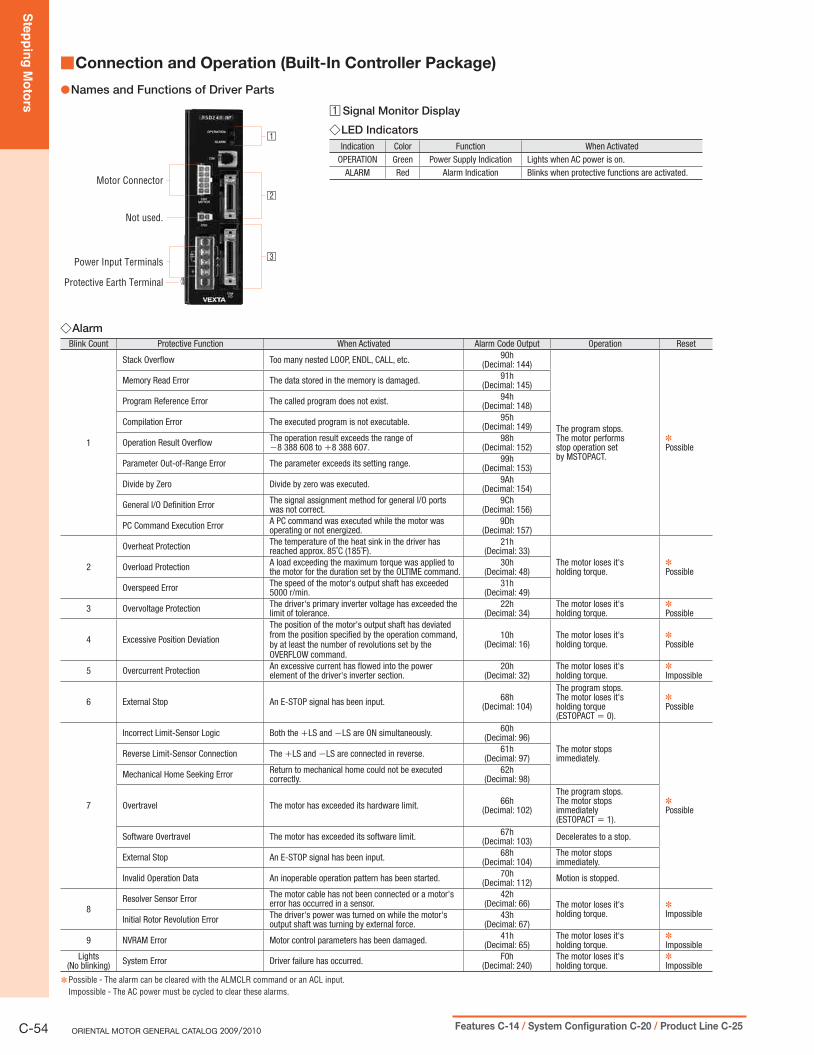
Ste
pp
ing
Mo
tors
C-54 ORIENTAL MOTOR GENERAL CATALOG 2009/2010 Features C-14 / System Configuration C-20 / Product Line C-25
Connection and Operation (Built-In Controller Package) ■
Names and Functions of Driver Parts ●
Motor Connector
Not used.
Power Input Terminals
Protective Earth Terminal
□1
□2
□3
Alarm ◇Blink Count Protective Function When Activated Alarm Code Output Operation Reset
1
Stack Overflow Too many nested LOOP, ENDL, CALL, etc. 90h(Decimal: 144)
The program stops.The motor performs stop operation set by MSTOPACT.
✽Possible
Memory Read Error The data stored in the memory is damaged. 91h(Decimal: 145)
Program Reference Error The called program does not exist. 94h(Decimal: 148)
Compilation Error The executed program is not executable. 95h(Decimal: 149)
Operation Result Overflow The operation result exceeds the range of −8 388 608 to +8 388 607.
98h(Decimal: 152)
Parameter Out-of-Range Error The parameter exceeds its setting range. 99h(Decimal: 153)
Divide by Zero Divide by zero was executed. 9Ah(Decimal: 154)
General I/O Definition Error The signal assignment method for general I/O ports was not correct.
9Ch(Decimal: 156)
PC Command Execution Error A PC command was executed while the motor was operating or not energized.
9Dh(Decimal: 157)
2
Overheat Protection The temperature of the heat sink in the driver has reached approx. 85˚C (185˚F).
21h(Decimal: 33)
The motor loses it'sholding torque.
✽PossibleOverload Protection A load exceeding the maximum torque was applied to
the motor for the duration set by the OLTIME command.30h
(Decimal: 48)
Overspeed Error The speed of the motor's output shaft has exceeded 5000 r/min.
31h(Decimal: 49)
3 Overvoltage Protection The driver's primary inverter voltage has exceeded the limit of tolerance.
22h(Decimal: 34)
The motor loses it'sholding torque.
✽Possible
4 Excessive Position Deviation
The position of the motor's output shaft has deviated from the position specified by the operation command, by at least the number of revolutions set by the OVERFLOW command.
10h(Decimal: 16)
The motor loses it'sholding torque.
✽Possible
5 Overcurrent Protection An excessive current has flowed into the power element of the driver's inverter section.
20h(Decimal: 32)
The motor loses it'sholding torque.
✽Impossible
6 External Stop An E-STOP signal has been input. 68h(Decimal: 104)
The program stops.The motor loses it'sholding torque(ESTOPACT = 0).
✽Possible
7
Incorrect Limit-Sensor Logic Both the +LS and −LS are ON simultaneously. 60h(Decimal: 96)
The motor stopsimmediately.
✽Possible
Reverse Limit-Sensor Connection The +LS and −LS are connected in reverse. 61h(Decimal: 97)
Mechanical Home Seeking Error Return to mechanical home could not be executed correctly.
62h(Decimal: 98)
Overtravel The motor has exceeded its hardware limit. 66h(Decimal: 102)
The program stops.The motor stopsimmediately (ESTOPACT = 1).
Software Overtravel The motor has exceeded its software limit. 67h(Decimal: 103) Decelerates to a stop.
External Stop An E-STOP signal has been input. 68h(Decimal: 104)
The motor stopsimmediately.
Invalid Operation Data An inoperable operation pattern has been started. 70h(Decimal: 112) Motion is stopped.
8Resolver Sensor Error The motor cable has not been connected or a motor's
error has occurred in a sensor.42h
(Decimal: 66) The motor loses it'sholding torque.
✽Impossible
Initial Rotor Revolution Error The driver's power was turned on while the motor's output shaft was turning by external force.
43h(Decimal: 67)
9 NVRAM Error Motor control parameters has been damaged. 41h(Decimal: 65)
The motor loses it'sholding torque.
✽Impossible
Lights(No blinking) System Error Driver failure has occurred. F0h
(Decimal: 240)The motor loses it'sholding torque.
✽Impossible
Possible - The alarm can be cleared with the ALMCLR command or an ACL input. ✽
Impossible - The AC power must be cycled to clear these alarms.
□1 Signal Monitor Display
LED Indicators ◇Indication Color Function When Activated
OPERATION Green Power Supply Indication Lights when AC power is on.ALARM Red Alarm Indication Blinks when protective functions are activated.
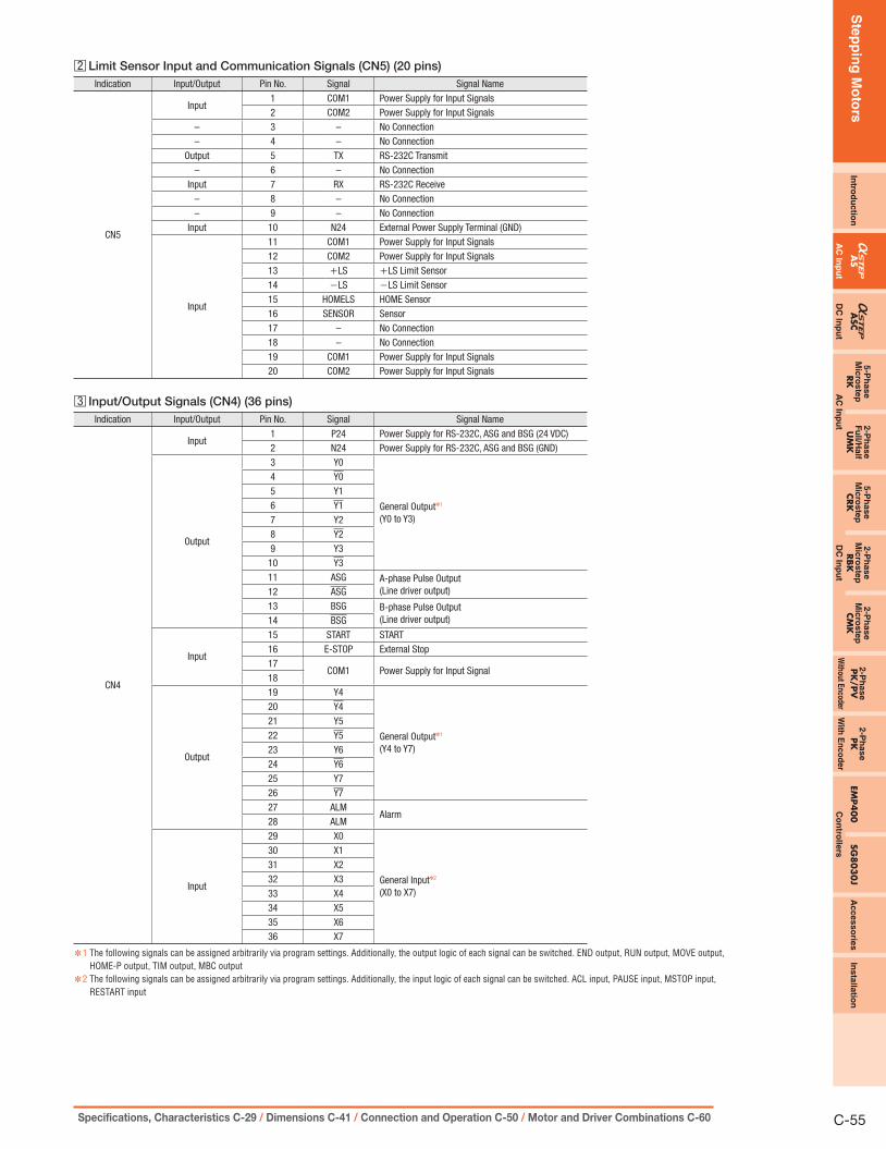
Ste
pp
ing
Mo
tors
Intro
du
ctio
nA
SA
SC5-P
hase
Mic
roste
pRK
2-P
hase
Fu
ll/Half
UM
K
5-P
hase
Mic
roste
pCRK
2-P
hase
Mic
roste
pRBK
2-P
hase
Mic
roste
pCM
K2-P
hase
PK
/PV
2-P
ha
se
PK
EMP40
0SG
803
0J
Accesso
ries
Ins
talla
tion
AC
Inp
ut
DC
Inp
ut
AC
Inp
ut
DC
Inp
ut
Without E
ncoderW
ith E
nc
od
er
Co
ntro
llers
C-55Specifications, Characteristics C-29 / Dimensions C-41 / Connection and Operation C-50 / Motor and Driver Combinations C-60
□2 Limit Sensor Input and Communication Signals (CN5) (20 pins)Indication Input/Output Pin No. Signal Signal Name
CN5
Input1 COM1 Power Supply for Input Signals2 COM2 Power Supply for Input Signals
– 3 – No Connection– 4 – No Connection
Output 5 TX RS-232C Transmit– 6 – No Connection
Input 7 RX RS-232C Receive– 8 – No Connection– 9 – No Connection
Input 10 N24 External Power Supply Terminal (GND)
Input
11 COM1 Power Supply for Input Signals12 COM2 Power Supply for Input Signals13 +LS +LS Limit Sensor14 −LS −LS Limit Sensor15 HOMELS HOME Sensor16 SENSOR Sensor17 – No Connection18 – No Connection19 COM1 Power Supply for Input Signals20 COM2 Power Supply for Input Signals
□3 Input/Output Signals (CN4) (36 pins)Indication Input/Output Pin No. Signal Signal Name
CN4
Input1 P24 Power Supply for RS-232C, ASG and BSG (24 VDC)2 N24 Power Supply for RS-232C, ASG and BSG (GND)
Output
3 Y0
General Output✽1
(Y0 to Y3)
4 Y05 Y16 Y17 Y28 Y29 Y310 Y311 ASG A-phase Pulse Output
(Line driver output)12 ASG13 BSG B-phase Pulse Output
(Line driver output)14 BSG
Input
15 START START16 E-STOP External Stop17
COM1 Power Supply for Input Signal18
Output
19 Y4
General Output✽1
(Y4 to Y7)
20 Y421 Y522 Y523 Y624 Y625 Y726 Y727 ALM
Alarm28 ALM
Input
29 X0
General Input✽2
(X0 to X7)
30 X131 X232 X333 X434 X535 X636 X7
1 ✽ The following signals can be assigned arbitrarily via program settings. Additionally, the output logic of each signal can be switched. END output, RUN output, MOVE output, HOME-P output, TIM output, MBC output
2 ✽ The following signals can be assigned arbitrarily via program settings. Additionally, the input logic of each signal can be switched. ACL input, PAUSE input, MSTOP input, RESTART input

Ste
pp
ing
Mo
tors
C-56 ORIENTAL MOTOR GENERAL CATALOG 2009/2010 Features C-14 / System Configuration C-20 / Product Line C-25
Notes on Wiring ◇Use input signals at 24 VDC ● ±10%.Use output signals at 30 VDC or below and at 4 to 8 mA. ●Use a shielded cable with a wire of a size ranging between AWG24 and AWG22 for ●the driver signal cable (I/O signals, limit sensors signals), and keep it as short as possible.When it is necessary to extend wiring distance between the motor and driver more ●than 0.4 m (1.31 ft.), the accessory extension cable or flexible extension cable must be used. Electromagnetic brake motor models [except motor frame size 42 mm (1.65 in.)] must use an electromagnetic brake extension cable or flexible extension cable (sold separately.) The frame size 42 mm (1.65 in.) models can use a standard extension cable even for electromagnetic brake motor models.Extension cables for electromagnetic brake motor ➜ Page C-297Always use the motor cable for industrial connector type motor (sold separately) for connection between the industrial connector type motor and the driver.Use the following cable for the power line ●Single-phase 100-115 VAC, Single-phase 200-230 VAC: 3-core cable of AWG18 or thickerThree-phase 200-230 VAC: 4-core cable of AWG18 or thickerProvide a minimum distance of 300 mm (1 ft.) between the control I/O signal line ●and power lines (AC lines, motor lines and other large-current circuits).Do not run the control I/O signal lines in the same duct as power lines or bundle them with power lines.To ground the driver, lead the ground conductor from the protective earth terminal ●(M4) and connect the ground conductor to provide a common ground point.
Recommended Crimp Terminals ◇ unit = mm (in.)
9 (0.35) min.6.2
(0.2
4) m
ax. 3.2 (0.13) min.
9 (0.35) min.6.2
(0.2
4) m
ax. 3.2 (0.13) min.
Crimp terminals are not provided with the products. They must be purchased ●separately.
Connection Diagrams ●
CN4
START InputE-STOP Input
X0 InputX1 InputX2 InputX3 InputX4 InputX5 InputX6 InputX7 Input
DriverHost Controller
P24
CN4
START InputE-STOP Input
X0 InputX1 InputX2 InputX3 InputX4 InputX5 InputX6 InputX7 Input
DriverHost Controller
+24 VY0 OutputY0 OutputY1 OutputY1 OutputY2 OutputY2 OutputY3 OutputY3 OutputY4 OutputY4 OutputY5 OutputY5 OutputY6 OutputY6 OutputY7 OutputY7 Output
ALM OutputALM Output
ASG OutputASG OutputBSG OutputBSG Output
N24
COM1
COM1 (CN5)
+24 V
0 V
P24
COM1
COM1 (CN5)
N24
2
1
1516293031323334
3536
3456
89
1019202122232425262728
7
Y0 OutputY0 OutputY1 OutputY1 OutputY2 OutputY2 OutputY3 OutputY3 OutputY4 OutputY4 OutputY5 OutputY5 OutputY6 OutputY6 OutputY7 OutputY7 Output
ALM OutputALM Output
3456
891019202122232425262728
7
17(18)2
17(18)
+24 V
0 V 0 V
14131211
ASG OutputASG OutputBSG OutputBSG Output
14131211
0 V
+24 V1
1516
29303132333435
36
⦁ Current Source Input and Current Sink Output ⦁ Current Sink Input and Current Source Output
Limit Sensor (CN5) ◇
Driver
CN5
+LS Input
−LS Input
HOMELS Input
SENSOR Input
+24 V
+24 V
0 V
COM1
Driver
CN5
+LS Input
−LS Input
HOMELS Input
SENSOR Input
COM1
0 V
⦁ Current Sink Input⦁ Current Source Input
16
13
14
15
1,11,19
COM1 (CN4) COM1 (CN4)
16
13
14
15
1,11,19
Connecting the Driver with a Personal Computer ◇(CN1)
●Pin Assignments and Connecting
GNDTX
N.C.RX
CN1(Viewed from the front side of driver)PC (9 pins)
8764325
✽
✽
✽Short pins 4 and 6 together, as well as pins 7 and 8 together
●Communication Specifi cations
Item DescriptionElectrical Characteristics In conformance with RS-232C
Transmission MethodStart-stop asynchronous method, NRZ (non-return to Zero), full-duplex
Data Length 8 bits, 1 stop bit, no parityTransmission Speed 9600 bpsProtocol TTY (CR+LF)Connector Specification Modular (4 lines, 4 pins)
Notes:
Confirm that 24 VDC is supplied to the driver's external power supply input ●terminals (P24 and N24).Use the RS-232C signal lines over the shortest possible distance. It is ●recommended that the signal lines be shielded to protect them from noise interference.The maximum distance between drivers when using a daisy chain connection ●should be 15 m (49.2 ft.).

Ste
pp
ing
Mo
tors
Intro
du
ctio
nA
SA
SC5-P
hase
Mic
roste
pRK
2-P
hase
Fu
ll/Half
UM
K
5-P
hase
Mic
roste
pCRK
2-P
hase
Mic
roste
pRBK
2-P
hase
Mic
roste
pCM
K2-P
hase
PK
/PV
2-P
hase
PK
EMP4
00
SG8
03
0J
Accesso
ries
Insta
llatio
n
AC
Inp
ut
DC
Inp
ut
AC
Inp
ut
DC
Inp
ut
Without E
ncoderW
ith E
nc
od
er
Co
ntro
llers
C-57Specifications, Characteristics C-29 / Dimensions C-41 / Connection and Operation C-50 / Motor and Driver Combinations C-60
■Connecting the Electromagnetic Brake to a Power SupplyConnect the electromagnetic brake to the power supply using a cable of at least AWG24. The power supply input to the electromagnetic brake is 24 VDC ±5% 0.3 A minimum (AS46: 0.1 A minimum) and therefore must be independent of the driver's power supply for signal control.
Notes:
Applying a voltage that exceeds the specifications will cause the electromagnetic brake to ●generate a great amount of heat, resulting in motor temperature rises and possible damage to the motor. Conversely, if voltage is too low, the electromagnetic brake may not release.To protect the switch contacts and prevent noise, always connect the surge suppressor. ● ✽
(✽The surge suppressor is included with electromagnetic brake motors.)To prevent noise, use a dedicated power supply for electromagnetic brake. ●Correct polarity ( ● + and −) must be ensured when connecting the electromagnetic brake leads of AS Series to the DC power supply. If polarity is incorrect, the electromagnetic brake will not operate. When using as a CE certified part, use a dedicated DC power supply for electromagnetic ●brake.
(1) AS46The electromagnetic brake leads are linked to the connector on the motor [600 mm (23.6 in.)].When connecting with the DC power supply, connect the red spiral lead wire to +24 V, and the black lead wire to the ground (GND). Use the extension cable or the flexible extension cable (both sold separately).
24 VDC
SurgeSuppressor✽
Switch
+ −Motor
AS Series Driver
Black
Red
Extension Cable(Sold separately)
(2) AS66, AS69, AS98The electromagnetic brake leads are linked to the connector on the driver connection side of extension cable for electromagnetic brake motor (sold separately). Be sure to use the accessory (sold separately) extension cable or flexible extension cable. Connect the orange/black spiral lead wire (orange for flexible extension cable)[60 mm (2.36 in.)] to +24 V, and the gray lead wire [60 mm (2.36 in.)] to the ground (GND).
Motor
AS Series Driver
Extension Cable forElectromagnetic
Brake Motor(Sold separately)
24 VDC
SurgeSuppressor✽
SwitchOrange/Black(Orange for flexible extension cable)Gray
− +
Description of Daisy Chain Connections ●Use the RS-232C communication pins (TX, RX and N24) of the
sensor connector (CN5) when connecting two or more drivers via a
daisy chain (up to 36 drivers).
5
3
4
6
2
7
8
PC (9-pin COM port)
GND
RX
TX
DTR
DSR
RTS
CTS
Driver 1
CN5
5 TX
N2410
7 RX
Driver 2
CN5
5 TX
N2410
7 RX
Driver N
CN5
5 TX
N2410
7 RX
TX, RX ◇These communication terminals are used when implementing daisy
chain connections.
Notes:
Confirm that 24 VDC is supplied to the driver's external power supply input terminals (P24 ●and N24).Use the RS-232C signal lines over the shortest possible distance. It is recommended that the ●signal lines be shielded to protect them from noise interference.The maximum distance between drivers when using a daisy chain connection should be 15 m ●(49.2 ft.). Do not use the RS-232C communication port (CN1). ●
ElectromagneticBrake Power Supply
OFF
ON
Driver Power Supply
To release the electromagnetic brake, wait at least 0.5 secondafter turning on the driver power supply.The load may fall down.
OFF
ON
0.5 s min.
Timing Chart for Electromagnetic Brake Operation

Ste
pp
ing
Mo
tors
C-58 ORIENTAL MOTOR GENERAL CATALOG 2009/2010 Features C-14 / System Configuration C-20 / Product Line C-25
Description of Input Signals (CN4) ●Input Circuit and Sample Connection ◇
+24 V
0 V
1 kΩ
4.7 kΩ
Controller Driver
∼
⑰ ⑱⑰ ⑱
Note:
Use input signals at 24 VDC ● ±10%.
P24 Input, N24 Input ◇These inputs are for the external power supply required for the
RS-232C communication, ASG and BSG outputs. Make sure to use
a power supply of at least 24 VDC±10%, 0.05 A.
If the same power supply is going to be used for the RS-232C, ASG,
BSG and other external I/O, make sure to use a power supply of at
least 24 VDC±10%, 0.2 A.
START Input ◇This signal starts the program named "STARTUP."
OFF➝ON edge to start "STARTUP" program.
E-STOP Input ◇This signal is used to forcibly stop the operation.
Set the stopping method using the ESTOPACT command.
Additionally, the input logic can be changed using the ESTOPLV
command. (The factory setting of this command is normally open.)
OFF➝ON edge to stop operation.
COM1 Input ◇This is an external power supply terminal for input signals.
This signal is internally connected to terminals COM1 of CN5.
X0 to X7 Inputs ◇The X0 thorough X7 inputs can be used as input ports for general
signals. The status of each port can be read using an IN command
or INx command.
The general signals assignable to the X0 through X7 inputs are listed
below. Use a corresponding command to assign signal.
ACL input ............INACL command
PAUSE input .......INPAUSE command
MSTOP input ......INMSTOP command
RESTART input ...INRESTART command
ACL Input ◇This signal is used to reset the alarm that has been generated by the
driver's protective function.
Input an ACL signal once after removing the cause that has triggered
the protective function.
Description of Output Signals (CN4) ●Output Circuit and Sample Connection ◇
Controller
DriverV0
0 V
,Y0 ∼ Y7, ALM
Y0 ∼ Y7, ALM
④④∼
③③∼
,
Note:
Use output signals at 30 VDC or below and at 4 to 8 mA. ●
Y0 to Y7 Outputs ◇The Y0 through Y7 outputs can be used as output ports for general
signals. The status of each port can be read using an OUT command
or OUTx command.
The general signals assignable to the Y0 through Y7 outputs are
listed below. Use the corresponding command to assign each signal.
END output ............. OUTEND command
RUN output ............. OUTRUN command
MOVE output .......... OUTMOVE command
HOME-P output ...... OUTHOMEP command
TIM output .............. OUTTIM command
MBC output ............ OUTMBC command
ASG Output, BSG Output ◇●Line driver output (26C31 or equivalent)
26C31 or Equivalent
ASG, BSG
ASG, BSG
Driver
ASG Output
BSG Output
H
L
H
L
90˚
A counter or similar device can be connected to monitor the
position of the motor. The pulse resolution is the same as the motor
resolution at the time of power-on.
[Example: Resolution select switch (1000 P/R) ➝ Output pulse
number for each motor revolution (1000).] The phase difference
between A and B is 90° in electrical angle.
Notes:
The pulse output accuracy is, regardless of resolution, within ● ±0.36° (repetition accuracy within ±0.09°).When the ● "Quadrature" signal output is used, 5 VDC or 24 VDC power supply is necessary. This signal is only for position verification when the motor has stopped. There is a 1 msec (maximum) time lag between real rotor motion and the output signals.
ALM Output ◇This signal is output when an alarm is generated by the driver's
protective function.
The reason for triggering of the protective function can be identified
through the blink count of the alarm LED, or ALM command.
To reset the ALM output, remove the cause of the alarm and then
perform one of the following procedures after ensuring safety:
Assign INACL then turn the ACL input to ON. ●Enter an ALMCLR command. ●Turn off the AC power, wait at least 10 seconds, then turn it back on. ●

Ste
pp
ing
Mo
tors
Intro
du
ctio
nA
SA
SC5-P
hase
Mic
roste
pRK
2-P
hase
Fu
ll/Half
UM
K
5-P
hase
Mic
roste
pCRK
2-P
hase
Mic
roste
pRBK
2-P
hase
Mic
roste
pCM
K2-P
hase
PK
/PV
2-P
hase
PK
EMP4
00
SG8
03
0J
Accesso
ries
Insta
llatio
n
AC
Inp
ut
DC
Inp
ut
AC
Inp
ut
DC
Inp
ut
Without E
ncoderW
ith E
nc
od
er
Co
ntro
llers
C-59Specifications, Characteristics C-29 / Dimensions C-41 / Connection and Operation C-50 / Motor and Driver Combinations C-60
Description of Limit Sensors (CN5) ●Input Circuit and Sample Connection ◇
+24 V
0 V
1 kΩ
4.7 kΩ
Controller Driver
① ⑪ ⑲
⑬∼⑯
Note:
Use input signals at 24 VDC ● ±10%.
COM1 Input ◇This is a power supply input terminal for limit-sensor signals. The
power supply voltage must be 24 VDC±10%.
This signal is internally connected to terminals COM1 of CN4.
COM2 Input ◇This is a power supply input terminal for limit-sensor signals.
Use it when sharing the input signal power supply among two or
more drivers.
+ ◇ LS Input, −LS InputThese signals are input from +LS and −LS.
The input logic can be changed using the OTLV command. (The
factory setting of this command is normally open.) Input logic for the
+LS input and −LS input cannot be set separately.
Continuous Operation and Positioning OperationWhen a +LS or −LS is detected, the driver's protective function
(overtravel) is activated. As a result, the ALM output is turned OFF
and the motor stops.
Set the stopping method using the OTACT command.
To pull out of +LS or −LS, cancel the protective function by
inputting an ACL signal once or by using the ALMCLR command.
Then perform return to mechanical home or operate the motor in
the direction opposite that of the limit sensor during continuous
operation.
Return to Mechanical HomeWhen a +LS or −LS is detected, the motor operates in the direction
opposite that of the detected limit.
HOMELS Input ◇This signal is input from HOMELS.
Connect the HOMELS when return to mechanical home is performed
in 3-sensor mode.
When return to mechanical home is performed in 3-sensor mode,
the HOMELS becomes the mechanical home. The input logic can be
changed using the HOMELV command. (The factory setting of this
command is normally open.)
SENSOR Input ◇This signal is input from SENSOR.
The input logic can be changed using the SENSORLV command.
(The factory setting of this command is normally open.)
Return to Mechanical HomeThis input is used when detecting the mechanical home at a specific
point on the motor's output shaft or load shaft using a slotted disc,
etc. The accuracy of return to mechanical home increases if this
input is used in conjunction with the TIM. signal.
Continuous OperationThe motor can be stopped forcibly upon the detection of SENSOR.
Set the stopping method using the SENSORACT command.
Note:
If the SENSOR input is used in return to mechanical home, it cannot be used during ●continuous operation.

Ste
pp
ing
Mo
tors
C-60 ORIENTAL MOTOR GENERAL CATALOG 2009/2010 Features C-14 / System Configuration C-20 / Product Line C-25
List of Motor and Driver Combinations ■
Model names for motor and driver combinations are shown below.
Power Supply Voltage
TypePulse Input Package Built-In Controller Package
Model Motor Model Driver Model Model Motor Model Driver Model
Sing
le-P
hase
100
-115
VAC
Inpu
t
Standard Type
AS46□A ASM46□A ASD13A-A AS46□AP ASM46□A ASD13A-APAS66□AE ASM66□AE ASD24A-A AS66□AEP ASM66□AE ASD24A-APAS69□AE ASM69□AE ASD30D-A AS69□AEP ASM69□AE ASD30D-APAS98□AE ASM98□AE ASD30A-A AS98□AEP ASM98□AE ASD30A-APAS911AAE ASM911AAE ASD30E-A AS911AAEP ASM911AAE ASD30E-AP
Standard Type Industrial Connector
AS66AAT ASM66AAT ASD24A-A AS66AATP ASM66AAT ASD24A-APAS69AAT ASM69AAT ASD30D-A AS69AATP ASM69AAT ASD30D-APAS98AAT ASM98AAT ASD30A-A AS98AATP ASM98AAT ASD30A-APAS911AAT ASM911AAT ASD30E-A AS911AATP ASM911AAT ASD30E-AP
TH Geared Type
AS46□A-T3.6 ASM46□A-T3.6ASD13B-A
AS46□AP-T3.6 ASM46□A-T3.6ASD13B-APAS46□A-T7.2 ASM46□A-T7.2 AS46□AP-T7.2 ASM46□A-T7.2
AS46□A-T10 ASM46□A-T10 AS46□AP-T10 ASM46□A-T10AS46□A-T20 ASM46□A-T20
ASD13C-AAS46□AP-T20 ASM46□A-T20
ASD13C-APAS46□A-T30 ASM46□A-T30 AS46□AP-T30 ASM46□A-T30AS66□AE-T3.6 ASM66□AE-T3.6
ASD24B-AAS66□AEP-T3.6 ASM66□AE-T3.6
ASD24B-APAS66□AE-T7.2 ASM66□AE-T7.2 AS66□AEP-T7.2 ASM66□AE-T7.2AS66□AE-T10 ASM66□AE-T10 AS66□AEP-T10 ASM66□AE-T10AS66□AE-T20 ASM66□AE-T20
ASD24C-AAS66□AEP-T20 ASM66□AE-T20
ASD24C-APAS66□AE-T30 ASM66□AE-T30 AS66□AEP-T30 ASM66□AE-T30AS98□AE-T3.6 ASM98□AE-T3.6
ASD30A-AAS98□AEP-T3.6 ASM98□AE-T3.6
ASD30A-APAS98□AE-T7.2 ASM98□AE-T7.2 AS98□AEP-T7.2 ASM98□AE-T7.2AS98□AE-T10 ASM98□AE-T10 AS98□AEP-T10 ASM98□AE-T10AS98□AE-T20 ASM98□AE-T20
ASD30C-AAS98□AEP-T20 ASM98□AE-T20
ASD30C-APAS98□AE-T30 ASM98□AE-T30 AS98□AEP-T30 ASM98□AE-T30
PN Geared Type
AS46□A-N7.2 ASM46□A-N7.2ASD13A-A
AS46□AP-N7.2 ASM46□A-N7.2ASD13A-AP
AS46□A-N10 ASM46□A-N10 AS46□AP-N10 ASM46□A-N10AS66□AE-N5 ASM66□AE-N5
ASD24A-AAS66□AEP-N5 ASM66□AE-N5
ASD24A-APAS66□AE-N7.2 ASM66□AE-N7.2 AS66□AEP-N7.2 ASM66□AE-N7.2AS66□AE-N10 ASM66□AE-N10 AS66□AEP-N10 ASM66□AE-N10AS66□AE-N25 ASM66□AE-N25 ASD24B-A AS66□AEP-N25 ASM66□AE-N25 ASD24B-APAS66□AE-N36 ASM66□AE-N36
ASD24C-AAS66□AEP-N36 ASM66□AE-N36
ASD24C-APAS66□AE-N50 ASM66□AE-N50 AS66□AEP-N50 ASM66□AE-N50AS98□AE-N5 ASM98□AE-N5
ASD30A-A
AS98□AEP-N5 ASM98□AE-N5
ASD30A-APAS98□AE-N7.2 ASM98□AE-N7.2 AS98□AEP-N7.2 ASM98□AE-N7.2AS98□AE-N10 ASM98□AE-N10 AS98□AEP-N10 ASM98□AE-N10AS98□AE-N25 ASM98□AE-N25 AS98□AEP-N25 ASM98□AE-N25AS98□AE-N36 ASM98□AE-N36 AS98□AEP-N36 ASM98□AE-N36AS98□AE-N50 ASM98□AE-N50 ASD30B-A AS98□AEP-N50 ASM98□AE-N50 ASD30B-AP
Harmonic Geared Type
AS46□A2-H50 ASM46□A2-H50ASD13A-A
AS46□AP2-H50 ASM46□A2-H50ASD13A-AP
AS46□A2-H100 ASM46□A2-H100 AS46□AP2-H100 ASM46□A2-H100AS66□AE-H50 ASM66□AE-H50 ASD24B-A AS66□AEP-H50 ASM66□AE-H50 ASD24B-APAS66□AE-H100 ASM66□AE-H100 ASD24C-A AS66□AEP-H100 ASM66□AE-H100 ASD24C-APAS98□AE-H50 ASM98□AE-H50
ASD30B-AAS98□AEP-H50 ASM98□AE-H50
ASD30B-APAS98□AE-H100 ASM98□AE-H100 AS98□AEP-H100 ASM98□AE-H100
Sing
le-P
hase
200
-230
VAC
Inpu
t Standard Type
AS66□CE ASM66□CE ASD12A-C AS66□CEP ASM66□CE ASD12A-CPAS69□CE ASM69□CE ASD16D-C AS69□CEP ASM69□CE ASD16D-CPAS98□CE ASM98□CE ASD16A-C AS98□CEP ASM98□CE ASD16A-CPAS911ACE ASM911ACE ASD20A-C AS911ACEP ASM911ACE ASD20A-CP
Standard Type Industrial Connector
AS66ACT ASM66ACT ASD12A-C AS66ACTP ASM66ACT ASD12A-CPAS69ACT ASM69ACT ASD16D-C AS69ACTP ASM69ACT ASD16D-CPAS98ACT ASM98ACT ASD16A-C AS98ACTP ASM98ACT ASD16A-CPAS911ACT ASM911ACT ASD20A-C AS911ACTP ASM911ACT ASD20A-CP
TH Geared Type
AS66□CE-T3.6 ASM66□CE-T3.6ASD12B-C
AS66□CEP-T3.6 ASM66□CE-T3.6ASD12B-CPAS66□CE-T7.2 ASM66□CE-T7.2 AS66□CEP-T7.2 ASM66□CE-T7.2
AS66□CE-T10 ASM66□CE-T10 AS66□CEP-T10 ASM66□CE-T10AS66□CE-T20 ASM66□CE-T20
ASD12C-CAS66□CEP-T20 ASM66□CE-T20
ASD12C-CPAS66□CE-T30 ASM66□CE-T30 AS66□CEP-T30 ASM66□CE-T30
Enter ● A (standard) or M (electromagnetic brake) in the box (□) within the model name.

Ste
pp
ing
Mo
tors
Intro
du
ctio
nA
SA
SC5-P
hase
Mic
roste
pRK
2-P
hase
Fu
ll/Half
UM
K
5-P
hase
Mic
roste
pCRK
2-P
hase
Mic
roste
pRBK
2-P
hase
Mic
roste
pCM
K2-P
hase
PK
/PV
2-P
hase
PK
EMP4
00
SG8
03
0J
Accesso
ries
Insta
llatio
n
AC
Inp
ut
DC
Inp
ut
AC
Inp
ut
DC
Inp
ut
Without E
ncoderW
ith E
nc
od
er
Co
ntro
llers
C-61Specifications, Characteristics C-29 / Dimensions C-41 / Connection and Operation C-50 / Motor and Driver Combinations C-60
Power Supply Voltage
TypePulse Input Package Built-In Controller Package
Model Motor Model Driver Model Model Motor Model Driver Model
Sing
le-P
hase
200
-230
VAC
Inpu
t
TH Geared Type
AS98□CE-T3.6 ASM98□CE-T3.6ASD16A-C
AS98□CEP-T3.6 ASM98□CE-T3.6ASD16A-CPAS98□CE-T7.2 ASM98□CE-T7.2 AS98□CEP-T7.2 ASM98□CE-T7.2
AS98□CE-T10 ASM98□CE-T10 AS98□CEP-T10 ASM98□CE-T10AS98□CE-T20 ASM98□CE-T20
ASD16C-CAS98□CEP-T20 ASM98□CE-T20
ASD16C-CPAS98□CE-T30 ASM98□CE-T30 AS98□CEP-T30 ASM98□CE-T30
PN Geared Type
AS66□CE-N5 ASM66□CE-N5ASD12A-C
AS66□CEP-N5 ASM66□CE-N5ASD12A-CPAS66□CE-N7.2 ASM66□CE-N7.2 AS66□CEP-N7.2 ASM66□CE-N7.2
AS66□CE-N10 ASM66□CE-N10 AS66□CEP-N10 ASM66□CE-N10AS66□CE-N25 ASM66□CE-N25 ASD12B-C AS66□CEP-N25 ASM66□CE-N25 ASD12B-CPAS66□CE-N36 ASM66□CE-N36
ASD12C-CAS66□CEP-N36 ASM66□CE-N36
ASD12C-CPAS66□CE-N50 ASM66□CE-N50 AS66□CEP-N50 ASM66□CE-N50AS98□CE-N5 ASM98□CE-N5
ASD16A-C
AS98□CEP-N5 ASM98□CE-N5
ASD16A-CPAS98□CE-N7.2 ASM98□CE-N7.2 AS98□CEP-N7.2 ASM98□CE-N7.2AS98□CE-N10 ASM98□CE-N10 AS98□CEP-N10 ASM98□CE-N10AS98□CE-N25 ASM98□CE-N25 AS98□CEP-N25 ASM98□CE-N25AS98□CE-N36 ASM98□CE-N36 AS98□CEP-N36 ASM98□CE-N36AS98□CE-N50 ASM98□CE-N50 ASD16B-C AS98□CEP-N50 ASM98□CE-N50 ASD16B-CP
Harmonic Geared Type
AS66□CE-H50 ASM66□CE-H50 ASD12B-C AS66□CEP-H50 ASM66□CE-H50 ASD12B-CPAS66□CE-H100 ASM66□CE-H100 ASD12C-C AS66□CEP-H100 ASM66□CE-H100 ASD12C-CPAS98□CE-H50 ASM98□CE-H50
ASD16B-CAS98□CEP-H50 ASM98□CE-H50
ASD16B-CPAS98□CE-H100 ASM98□CE-H100 AS98□CEP-H100 ASM98□CE-H100
Thre
e-Ph
ase
200-
230
VAC
Inpu
t
Standard Type
AS66□SE ASM66□CE ASD12A-S AS66□SEP ASM66□CE ASD12A-SPAS69□SE ASM69□CE ASD16D-S AS69□SEP ASM69□CE ASD16D-SPAS98□SE ASM98□CE ASD16A-S AS98□SEP ASM98□CE ASD16A-SPAS911ASE ASM911ACE ASD20A-S AS911ASEP ASM911ACE ASD20A-SP
Standard Type Industrial Connector
AS66AST ASM66ACT ASD12A-S AS66ASTP ASM66ACT ASD12A-SPAS69AST ASM69ACT ASD16D-S AS69ASTP ASM69ACT ASD16D-SPAS98AST ASM98ACT ASD16A-S AS98ASTP ASM98ACT ASD16A-SPAS911AST ASM911ACT ASD20A-S AS911ASTP ASM911ACT ASD20A-SP
TH Geared Type
AS66□SE-T3.6 ASM66□CE-T3.6ASD12B-S
AS66□SEP-T3.6 ASM66□CE-T3.6ASD12B-SPAS66□SE-T7.2 ASM66□CE-T7.2 AS66□SEP-T7.2 ASM66□CE-T7.2
AS66□SE-T10 ASM66□CE-T10 AS66□SEP-T10 ASM66□CE-T10AS66□SE-T20 ASM66□CE-T20
ASD12C-SAS66□SEP-T20 ASM66□CE-T20
ASD12C-SPAS66□SE-T30 ASM66□CE-T30 AS66□SEP-T30 ASM66□CE-T30AS98□SE-T3.6 ASM98□CE-T3.6
ASD16A-SAS98□SEP-T3.6 ASM98□CE-T3.6
ASD16A-SPAS98□SE-T7.2 ASM98□CE-T7.2 AS98□SEP-T7.2 ASM98□CE-T7.2AS98□SE-T10 ASM98□CE-T10 AS98□SEP-T10 ASM98□CE-T10AS98□SE-T20 ASM98□CE-T20
ASD16C-SAS98□SEP-T20 ASM98□CE-T20
ASD16C-SPAS98□SE-T30 ASM98□CE-T30 AS98□SEP-T30 ASM98□CE-T30
PN Geared Type
AS66□SE-N5 ASM66□CE-N5ASD12A-S
AS66□SEP-N5 ASM66□CE-N5ASD12A-SPAS66□SE-N7.2 ASM66□CE-N7.2 AS66□SEP-N7.2 ASM66□CE-N7.2
AS66□SE-N10 ASM66□CE-N10 AS66□SEP-N10 ASM66□CE-N10AS66□SE-N25 ASM66□CE-N25 ASD12B-S AS66□SEP-N25 ASM66□CE-N25 ASD12B-SPAS66□SE-N36 ASM66□CE-N36
ASD12C-SAS66□SEP-N36 ASM66□CE-N36
ASD12C-SPAS66□SE-N50 ASM66□CE-N50 AS66□SEP-N50 ASM66□CE-N50AS98□SE-N5 ASM98□CE-N5
ASD16A-S
AS98□SEP-N5 ASM98□CE-N5
ASD16A-SPAS98□SE-N7.2 ASM98□CE-N7.2 AS98□SEP-N7.2 ASM98□CE-N7.2AS98□SE-N10 ASM98□CE-N10 AS98□SEP-N10 ASM98□CE-N10AS98□SE-N25 ASM98□CE-N25 AS98□SEP-N25 ASM98□CE-N25AS98□SE-N36 ASM98□CE-N36 AS98□SEP-N36 ASM98□CE-N36AS98□SE-N50 ASM98□CE-N50 ASD16B-S AS98□SEP-N50 ASM98□CE-N50 ASD16B-SP
Harmonic Geared Type
AS66□SE-H50 ASM66□CE-H50 ASD12B-S AS66□SEP-H50 ASM66□CE-H50 ASD12B-SPAS66□SE-H100 ASM66□CE-H100 ASD12C-S AS66□SEP-H100 ASM66□CE-H100 ASD12C-SPAS98□SE-H50 ASM98□CE-H50
ASD16B-SAS98□SEP-H50 ASM98□CE-H50
ASD16B-SPAS98□SE-H100 ASM98□CE-H100 AS98□SEP-H100 ASM98□CE-H100
Enter ● A (standard) or M (electromagnetic brake) in the box (□) within the model name.