introduction - escuela politécnica...
TRANSCRIPT
1Introduction
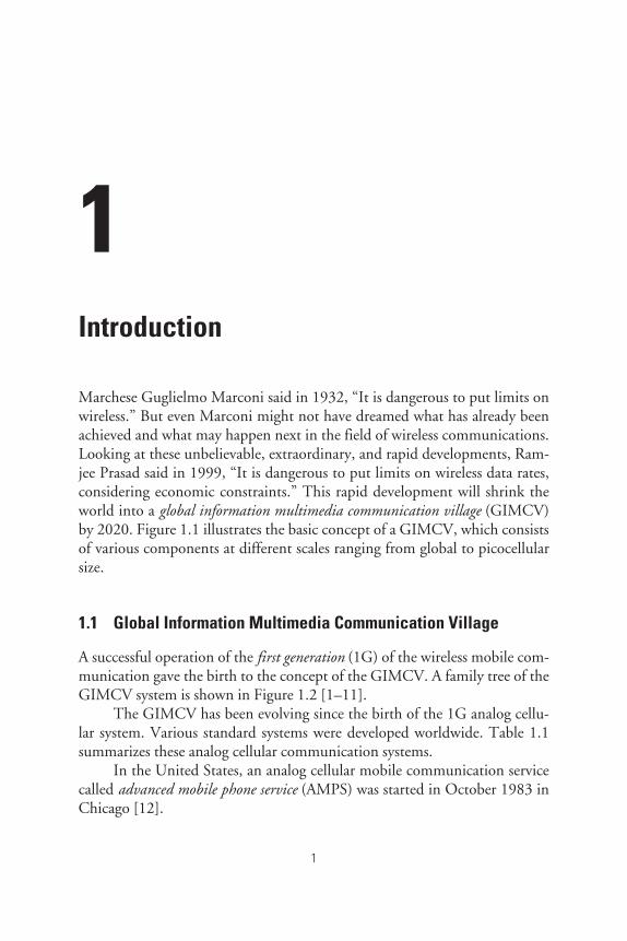
Marchese Guglielmo Marconi said in 1932, “It is dangerous to put limits onwireless.” But even Marconi might not have dreamed what has already beenachieved and what may happen next in the field of wireless communications.Looking at these unbelievable, extraordinary, and rapid developments, Ram-jee Prasad said in 1999, “It is dangerous to put limits on wireless data rates,considering economic constraints.” This rapid development will shrink theworld into a global information multimedia communication village (GIMCV)by 2020. Figure 1.1 illustrates the basic concept of a GIMCV, which consistsof various components at different scales ranging from global to picocellularsize.
1.1 Global Information Multimedia Communication Village
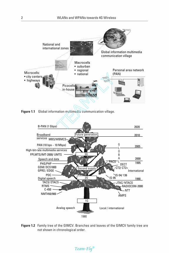
A successful operation of the first generation (1G) of the wireless mobile com-munication gave the birth to the concept of the GIMCV. A family tree of theGIMCV system is shown in Figure 1.2 [1–11].
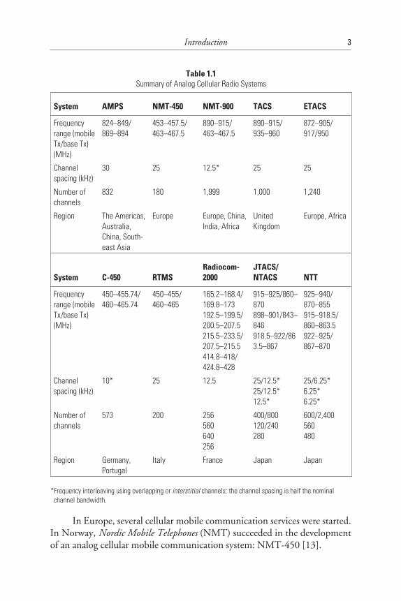
The GIMCV has been evolving since the birth of the 1G analog cellu-lar system. Various standard systems were developed worldwide. Table 1.1summarizes these analog cellular communication systems.
In the United States, an analog cellular mobile communication servicecalled advanced mobile phone service (AMPS) was started in October 1983 inChicago [12].
1
2 WLANs and WPANs towards 4G Wireless
Figure 1.1 Global information multimedia communication village.
Figure 1.2 Family tree of the GIMCV. Branches and leaves of the GIMCV family tree arenot shown in chronological order.
TEAMFLY
Team-Fly®
In Europe, several cellular mobile communication services were started.In Norway, Nordic Mobile Telephones (NMT) succeeded in the developmentof an analog cellular mobile communication system: NMT-450 [13].
Introduction 3
Table 1.1Summary of Analog Cellular Radio Systems
System AMPS NMT-450 NMT-900 TACS ETACS
Frequencyrange (mobileTx/base Tx)(MHz)
824–849/869–894
453–457.5/463–467.5
890–915/463–467.5
890–915/935–960
872–905/917/950
Channelspacing (kHz)
30 25 12.5* 25 25
Number ofchannels
832 180 1,999 1,000 1,240
Region The Americas,Australia,China, South-east Asia
Europe Europe, China,India, Africa
UnitedKingdom
Europe, Africa
System C-450 RTMSRadiocom-2000
JTACS/NTACS NTT
Frequencyrange (mobileTx/base Tx)(MHz)
450–455.74/460–465.74
450–455/460–465
165.2–168.4/169.8–173192.5–199.5/200.5–207.5215.5–233.5/207.5–215.5414.8–418/424.8–428
915–925/860–870898–901/843–846918.5–922/863.5–867
925–940/870–855915–918.5/860–863.5922–925/867–870
Channelspacing (kHz)
10* 25 12.5 25/12.5*25/12.5*12.5*
25/6.25*6.25*6.25*
Number ofchannels
573 200 256560640256
400/800120/240280
600/2,400560480
Region Germany,Portugal
Italy France Japan Japan
*Frequency interleaving using overlapping or interstitial channels; the channel spacing is half the nominal*channel bandwidth.
In the United Kingdom, Motorola developed an analog cellular mobilecommunication system called the total access communication system (TACS)based on AMPS in the 1984–1985 period. In 1983, NMT started a modifiedNMT-450 called NMT-900. C-450, Radio Telephone Mobile System(RTMS), and Radiocom-2000 were introduced in Germany, Italy, andFrance, respectively.
Meanwhile, in Japan, Nippon Telephone and Telegraph (NTT) devel-oped a cellular mobile communication system in the 800-MHz frequencyband and began service in Tokyo in December 1979. Furthermore, a modi-fied TACS that changed the frequency band to adjust for Japanese frequencyplanning and celled JTACS was also introduced in July 1989. Subsequently,narrowband TACS (NTACS), which reduced the required frequency band inhalf, started service in October 1991.
So far, we described the evolution of the analog cellular mobile com-munication system. However, the incompatibility of the various systems pre-cluded roaming. This meant that users had to change their mobile terminalswhen they moved to another country. In addition, analog cellular mobilecommunication systems were unable to ensure sufficient capacity for theincreasing number of users and the speech quality was not good.
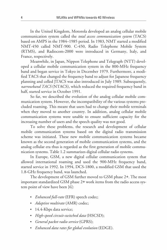
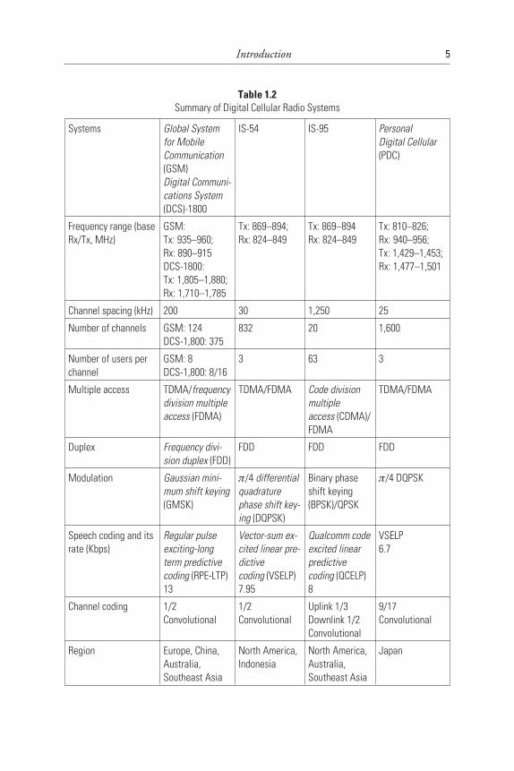
To solve these problems, the research and development of cellularmobile communication systems based on the digital radio transmissionscheme was initiated. These new mobile communication systems becameknown as the second generation of mobile communication systems, and theanalog cellular era thus is regarded as the first generation of mobile commu-nication systems. Table 1.2 summarizes digital cellular radio systems.
In Europe, GSM, a new digital cellular communication system thatallowed international roaming and used the 900-MHz frequency band,started service in 1992. In 1994, DCS-1800, a modified GSM that used the1.8-GHz frequency band, was launched.
The development of GSM further moved to GSM phase 2+. The mostimportant standardized GSM phase 2+ work items from the radio access sys-tem point of view have been [6]:
• Enhanced full-rate (EFR) speech codec;
• Adaptive multirate (AMR) codec;
• 14.4-Kbps data service;
• High-speed circuit-switched data (HSCSD);
• General packet radio service (GPRS);
• Enhanced data rates for global evolution (EDGE).
4 WLANs and WPANs towards 4G Wireless
Introduction 5
Table 1.2Summary of Digital Cellular Radio Systems
Systems Global Systemfor MobileCommunication(GSM)Digital Communi-cations System(DCS)-1800
IS-54 IS-95 PersonalDigital Cellular(PDC)
Frequency range (baseRx/Tx, MHz)
GSM:Tx: 935–960;Rx: 890–915DCS-1800:Tx: 1,805–1,880;Rx: 1,710–1,785
Tx: 869–894;Rx: 824–849
Tx: 869–894Rx: 824–849
Tx: 810–826;Rx: 940–956;Tx: 1,429–1,453;Rx: 1,477–1,501
Channel spacing (kHz) 200 30 1,250 25
Number of channels GSM: 124DCS-1,800: 375
832 20 1,600
Number of users perchannel
GSM: 8DCS-1,800: 8/16
3 63 3
Multiple access TDMA/frequencydivision multipleaccess (FDMA)
TDMA/FDMA Code divisionmultipleaccess (CDMA)/FDMA
TDMA/FDMA
Duplex Frequency divi-sion duplex (FDD)
FDD FDD FDD
Modulation Gaussian mini-mum shift keying(GMSK)
π/4 differentialquadraturephase shift key-ing (DQPSK)
Binary phaseshift keying(BPSK)/QPSK
π/4 DQPSK
Speech coding and itsrate (Kbps)
Regular pulseexciting-longterm predictivecoding (RPE-LTP)13
Vector-sum ex-cited linear pre-dictivecoding (VSELP)7.95
Qualcomm codeexcited linearpredictivecoding (QCELP)8
VSELP6.7
Channel coding 1/2Convolutional
1/2Convolutional
Uplink 1/3Downlink 1/2Convolutional
9/17Convolutional
Region Europe, China,Australia,Southeast Asia
North America,Indonesia
North America,Australia,Southeast Asia
Japan
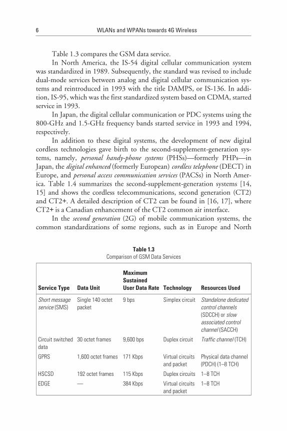
Table 1.3 compares the GSM data service.In North America, the IS-54 digital cellular communication system
was standardized in 1989. Subsequently, the standard was revised to includedual-mode services between analog and digital cellular communication sys-tems and reintroduced in 1993 with the title DAMPS, or IS-136. In addi-tion, IS-95, which was the first standardized system based on CDMA, startedservice in 1993.
In Japan, the digital cellular communication or PDC systems using the800-GHz and 1.5-GHz frequency bands started service in 1993 and 1994,respectively.
In addition to these digital systems, the development of new digitalcordless technologies gave birth to the second-supplement-generation sys-tems, namely, personal handy-phone systems (PHSs)—formerly PHPs—inJapan, the digital enhanced (formerly European) cordless telephone (DECT) inEurope, and personal access communication services (PACSs) in North Amer-ica. Table 1.4 summarizes the second-supplement-generation systems [14,15] and shows the cordless telecommunications, second generation (CT2)and CT2+. A detailed description of CT2 can be found in [16, 17], whereCT2+ is a Canadian enhancement of the CT2 common air interface.
In the second generation (2G) of mobile communication systems, thecommon standardizations of some regions, such as in Europe and North
6 WLANs and WPANs towards 4G Wireless
Table 1.3Comparison of GSM Data Services
Service Type Data Unit
MaximumSustainedUser Data Rate Technology Resources Used
Short messageservice (SMS)
Single 140 octetpacket
9 bps Simplex circuit Standalone dedicatedcontrol channels(SDCCH) or slowassociated controlchannel (SACCH)
Circuit switcheddata
30 octet frames 9,600 bps Duplex circuit Traffic channel (TCH)
GPRS 1,600 octet frames 171 Kbps Virtual circuitsand packet
Physical data channel(PDCH) (1–8 TCH)
HSCSD 192 octet frames 115 Kbps Duplex circuits 1–8 TCH
EDGE — 384 Kbps Virtual circuitsand packet
1–8 TCH
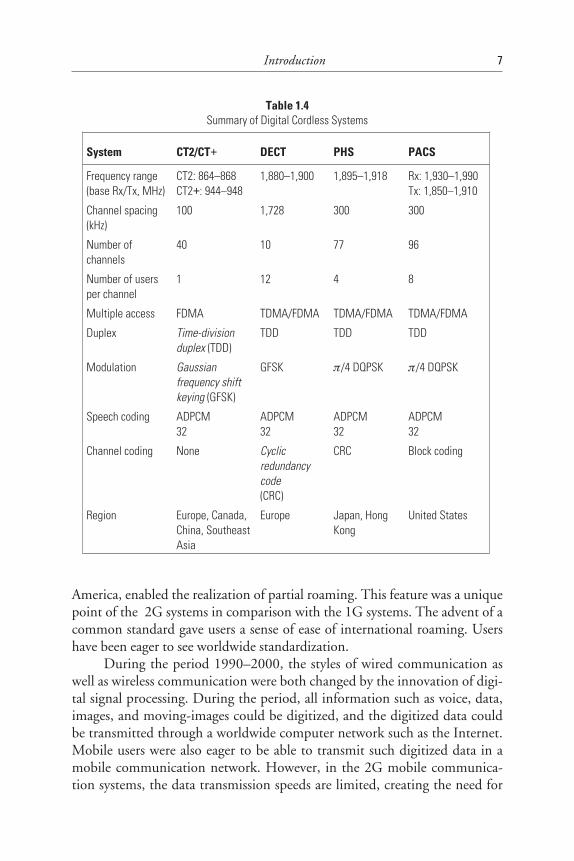
America, enabled the realization of partial roaming. This feature was a uniquepoint of the 2G systems in comparison with the 1G systems. The advent of acommon standard gave users a sense of ease of international roaming. Usershave been eager to see worldwide standardization.
During the period 1990–2000, the styles of wired communication aswell as wireless communication were both changed by the innovation of digi-tal signal processing. During the period, all information such as voice, data,images, and moving-images could be digitized, and the digitized data couldbe transmitted through a worldwide computer network such as the Internet.Mobile users were also eager to be able to transmit such digitized data in amobile communication network. However, in the 2G mobile communica-tion systems, the data transmission speeds are limited, creating the need for
Introduction 7
Table 1.4Summary of Digital Cordless Systems
System CT2/CT+ DECT PHS PACS
Frequency range(base Rx/Tx, MHz)
CT2: 864–868CT2+: 944–948
1,880–1,900 1,895–1,918 Rx: 1,930–1,990Tx: 1,850–1,910
Channel spacing(kHz)
100 1,728 300 300
Number ofchannels
40 10 77 96
Number of usersper channel
1 12 4 8
Multiple access FDMA TDMA/FDMA TDMA/FDMA TDMA/FDMA
Duplex Time-divisionduplex (TDD)
TDD TDD TDD
Modulation Gaussianfrequency shiftkeying (GFSK)
GFSK π/4 DQPSK π/4 DQPSK
Speech coding ADPCM32
ADPCM32
ADPCM32
ADPCM32
Channel coding None Cyclicredundancycode(CRC)
CRC Block coding
Region Europe, Canada,China, SoutheastAsia
Europe Japan, HongKong
United States
new high-speed mobile communication systems. Based on this objective,research and development into third generation (3G) mobile communicationsystems were started in 1995. The research and development that occurred inthe 1995–2000 period can be categorized into two areas:
1. International standardized high-speed digital cellular systems withmobility as the second generation;
2. International standardized broadband mobile-access system withlow mobility.
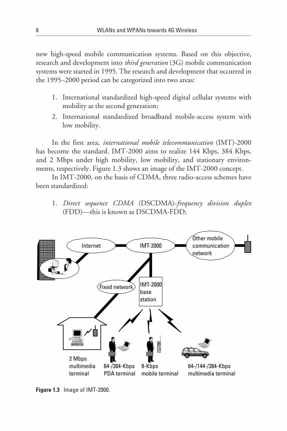
In the first area, international mobile telecommunication (IMT)-2000has become the standard. IMT-2000 aims to realize 144 Kbps, 384 Kbps,and 2 Mbps under high mobility, low mobility, and stationary environ-ments, respectively. Figure 1.3 shows an image of the IMT-2000 concept.
In IMT-2000, on the basis of CDMA, three radio-access schemes havebeen standardized:
1. Direct sequence CDMA (DSCDMA)-frequency division duplex(FDD)—this is known as DSCDMA-FDD;
8 WLANs and WPANs towards 4G Wireless
Figure 1.3 Image of IMT-2000.
2. Multicarrier CDMA (MCCDMA)-FDD—this is known asMCCDMA-FDD;
3. DSCDMA-TDD.
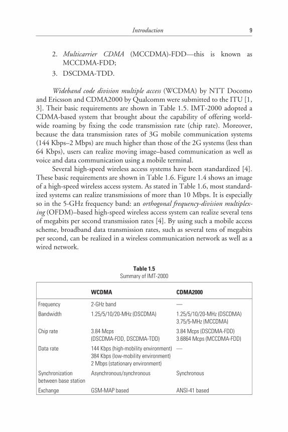
Wideband code division multiple access (WCDMA) by NTT Docomoand Ericsson and CDMA2000 by Qualcomm were submitted to the ITU [1,3]. Their basic requirements are shown in Table 1.5. IMT-2000 adopted aCDMA-based system that brought about the capability of offering world-wide roaming by fixing the code transmission rate (chip rate). Moreover,because the data transmission rates of 3G mobile communication systems(144 Kbps–2 Mbps) are much higher than those of the 2G systems (less than64 Kbps), users can realize moving image–based communication as well asvoice and data communication using a mobile terminal.
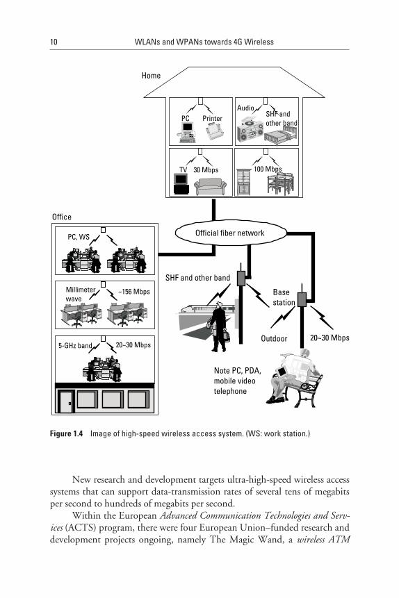
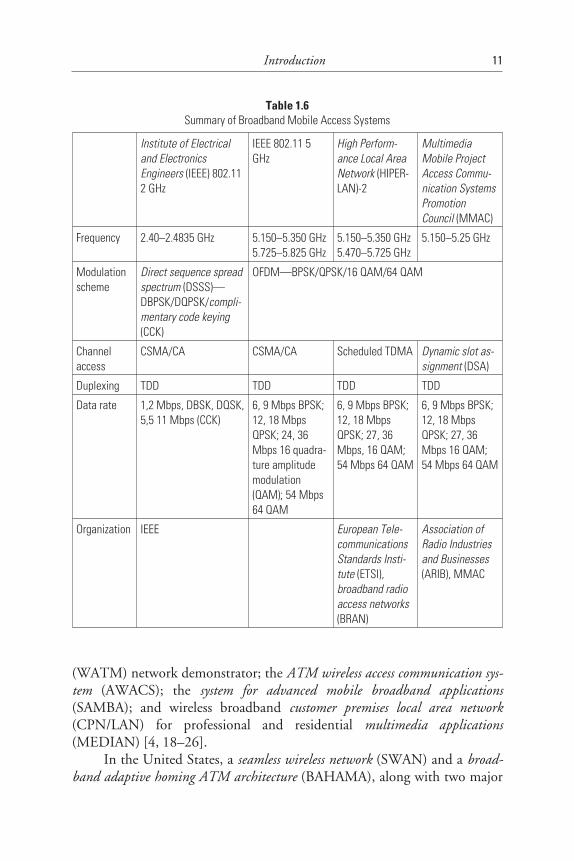
Several high-speed wireless access systems have been standardized [4].These basic requirements are shown in Table 1.6. Figure 1.4 shows an imageof a high-speed wireless access system. As stated in Table 1.6, most standard-ized systems can realize transmissions of more than 10 Mbps. It is especiallyso in the 5-GHz frequency band: an orthogonal frequency-division multiplex-ing (OFDM)–based high-speed wireless access system can realize several tensof megabits per second transmission rates [4]. By using such a mobile accessscheme, broadband data transmission rates, such as several tens of megabitsper second, can be realized in a wireless communication network as well as awired network.
Introduction 9
Table 1.5Summary of IMT-2000
WCDMA CDMA2000
Frequency 2-GHz band —
Bandwidth 1.25/5/10/20-MHz (DSCDMA) 1.25/5/10/20-MHz (DSCDMA)3.75/5-MHz (MCCDMA)
Chip rate 3.84 Mcps(DSCDMA-FDD, DSCDMA-TDD)
3.84 Mcps (DSCDMA-FDD)3.6864 Mcps (MCCDMA-FDD)
Data rate 144 Kbps (high-mobility environment)384 Kbps (low-mobility environment)2 Mbps (stationary environment)
—
Synchronizationbetween base station
Asynchronous/synchronous Synchronous
Exchange GSM-MAP based ANSI-41 based
New research and development targets ultra-high-speed wireless accesssystems that can support data-transmission rates of several tens of megabitsper second to hundreds of megabits per second.
Within the European Advanced Communication Technologies and Serv-ices (ACTS) program, there were four European Union–funded research anddevelopment projects ongoing, namely The Magic Wand, a wireless ATM
10 WLANs and WPANs towards 4G Wireless
Figure 1.4 Image of high-speed wireless access system. (WS: work station.)
(WATM) network demonstrator; the ATM wireless access communication sys-tem (AWACS); the system for advanced mobile broadband applications(SAMBA); and wireless broadband customer premises local area network(CPN/LAN) for professional and residential multimedia applications(MEDIAN) [4, 18–26].
In the United States, a seamless wireless network (SWAN) and a broad-band adaptive homing ATM architecture (BAHAMA), along with two major
Introduction 11
Table 1.6Summary of Broadband Mobile Access Systems
Institute of Electricaland ElectronicsEngineers (IEEE) 802.112 GHz
IEEE 802.11 5GHz
High Perform-ance Local AreaNetwork (HIPER-LAN)-2
MultimediaMobile ProjectAccess Commu-nication SystemsPromotionCouncil (MMAC)
Frequency 2.40–2.4835 GHz 5.150–5.350 GHz5.725–5.825 GHz
5.150–5.350 GHz5.470–5.725 GHz
5.150–5.25 GHz
Modulationscheme
Direct sequence spreadspectrum (DSSS)—DBPSK/DQPSK/compli-mentary code keying(CCK)
OFDM—BPSK/QPSK/16 QAM/64 QAM
Channelaccess
CSMA/CA CSMA/CA Scheduled TDMA Dynamic slot as-signment (DSA)
Duplexing TDD TDD TDD TDD
Data rate 1,2 Mbps, DBSK, DQSK,5,5 11 Mbps (CCK)
6, 9 Mbps BPSK;12, 18 MbpsQPSK; 24, 36Mbps 16 quadra-ture amplitudemodulation(QAM); 54 Mbps64 QAM
6, 9 Mbps BPSK;12, 18 MbpsQPSK; 27, 36Mbps, 16 QAM;54 Mbps 64 QAM
6, 9 Mbps BPSK;12, 18 MbpsQPSK; 27, 36Mbps 16 QAM;54 Mbps 64 QAM
Organization IEEE European Tele-communicationsStandards Insti-tute (ETSI),broadband radioaccess networks(BRAN)
Association ofRadio Industriesand Businesses(ARIB), MMAC
projects at Bell Laboratories and the WATM network (WATMnet), are beingdeveloped in the computer and communication (C&C) research laboratoriesof Nippon Electric Company (NEC) [18–22].
In Japan, the Communications Research Laboratory (CRL), in theMinistry of Posts and Telecommunications is busy with several research anddevelopment projects, such as a broadband mobile communication system[27] in the super-high-frequency (SHF) band (from 3 to 10 GHz) with achannel bit rate of up to 10 Mbps, which achieves 5-Mbps transmission in ahigh-mobility environment where the vehicle speed is 80 km/hr [28, 29].Moreover, an indoor high-speed wireless LAN in the millimeter-wave bandwith a target bit rate of up to 155 Mbps [30, 31] has also been researched,and a point-to-multipoint wireless LAN that can achieve a transmission rateof 156 Mbps by using an original protocol named reservation-based slottedidle signal multiple access (RS-ISMA) was developed [32].
As a mobile communication system that requires broadband transmis-sion capability, such as several megabits per second to 10 Mbps, in a high-mobility environment, the intelligent transport system (ITS) is the most repre-sentative example [33–37].
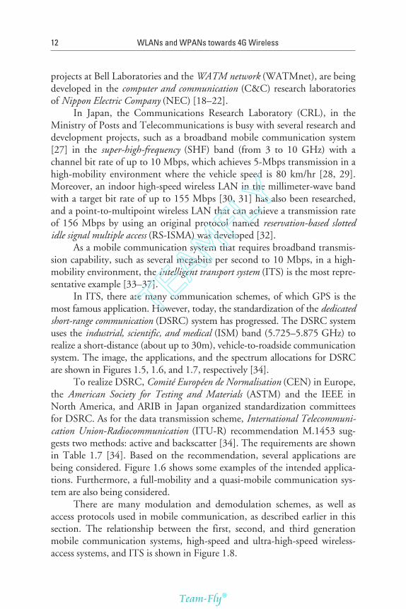
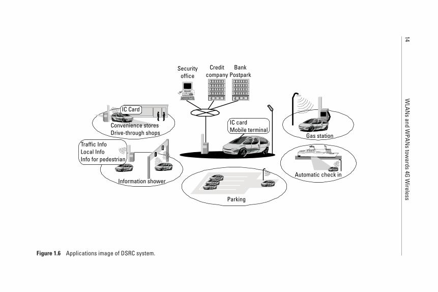
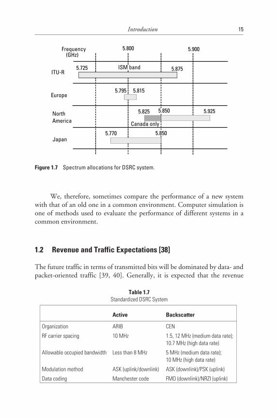
In ITS, there are many communication schemes, of which GPS is themost famous application. However, today, the standardization of the dedicatedshort-range communication (DSRC) system has progressed. The DSRC systemuses the industrial, scientific, and medical (ISM) band (5.725–5.875 GHz) torealize a short-distance (about up to 30m), vehicle-to-roadside communicationsystem. The image, the applications, and the spectrum allocations for DSRCare shown in Figures 1.5, 1.6, and 1.7, respectively [34].
To realize DSRC, Comité Européen de Normalisation (CEN) in Europe,the American Society for Testing and Materials (ASTM) and the IEEE inNorth America, and ARIB in Japan organized standardization committeesfor DSRC. As for the data transmission scheme, International Telecommuni-cation Union-Radiocommunication (ITU-R) recommendation M.1453 sug-gests two methods: active and backscatter [34]. The requirements are shownin Table 1.7 [34]. Based on the recommendation, several applications arebeing considered. Figure 1.6 shows some examples of the intended applica-tions. Furthermore, a full-mobility and a quasi-mobile communication sys-tem are also being considered.
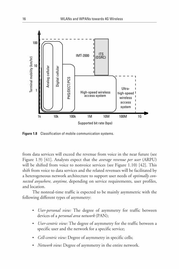
There are many modulation and demodulation schemes, as well asaccess protocols used in mobile communication, as described earlier in thissection. The relationship between the first, second, and third generationmobile communication systems, high-speed and ultra-high-speed wireless-access systems, and ITS is shown in Figure 1.8.
12 WLANs and WPANs towards 4G Wireless
TEAMFLY
Team-Fly®
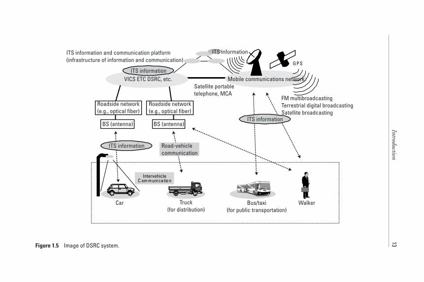
Introduction13Figure 1.5 Image of DSRC system.
14W
LANs
andW
PANs
towards
4GW
ireless
Figure 1.6 Applications image of DSRC system.
We, therefore, sometimes compare the performance of a new systemwith that of an old one in a common environment. Computer simulation isone of methods used to evaluate the performance of different systems in acommon environment.
1.2 Revenue and Traffic Expectations [38]
The future traffic in terms of transmitted bits will be dominated by data- andpacket-oriented traffic [39, 40]. Generally, it is expected that the revenue
Introduction 15
Table 1.7Standardized DSRC System
Active Backscatter
Organization ARIB CEN
RF carrier spacing 10 MHz 1.5, 12 MHz (medium data rate);10.7 MHz (high data rate)
Allowable occupied bandwidth Less than 8 MHz 5 MHz (medium data rate);10 MHz (high data rate)
Modulation method ASK (uplink/downlink) ASK (downlink)/PSK (uplink)
Data coding Manchester code FMO (downlink)/NRZI (uplink)
Figure 1.7 Spectrum allocations for DSRC system.
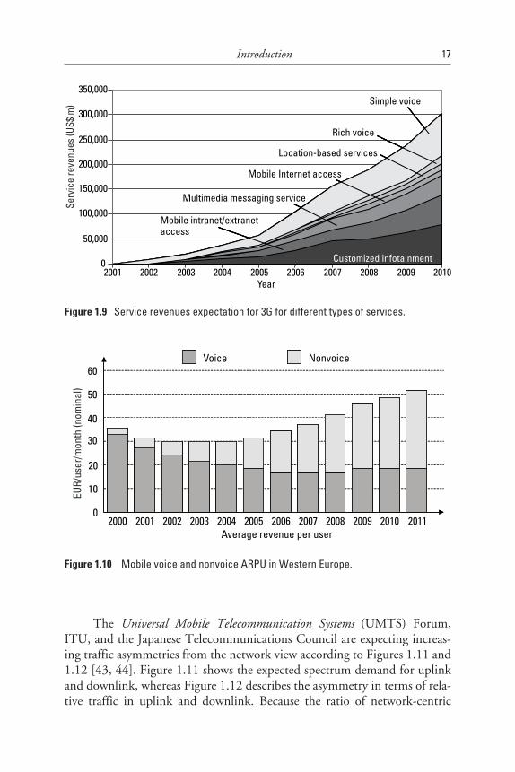
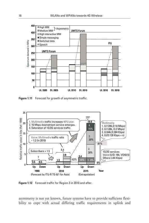
from data services will exceed the revenue from voice in the near future (seeFigure 1.9) [41]. Analysts expect that the average revenue per user (ARPU)will be shifted from voice to nonvoice services (see Figure 1.10) [42]. Thisshift from voice to data services and the related revenues will be facilitated bya heterogeneous network architecture to support user needs of optimally con-nected anywhere, anytime, depending on service requirements, user profiles,and location.
The nonreal-time traffic is expected to be mainly asymmetric with thefollowing different types of asymmetry:
• User-personal view: The degree of asymmetry for traffic betweendevices of a personal area network (PAN);
• User-centric view: The degree of asymmetry for the traffic between aspecific user and the network for a specific service;
• Cell-centric view: Degree of asymmetry in specific cells;
• Network view: Degree of asymmetry in the entire network.
16 WLANs and WPANs towards 4G Wireless
Figure 1.8 Classification of mobile communication systems.
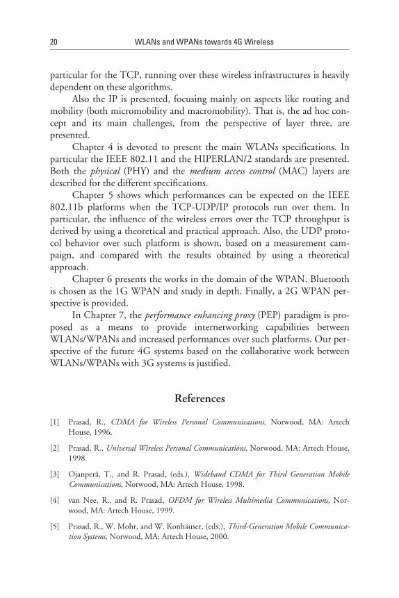
The Universal Mobile Telecommunication Systems (UMTS) Forum,ITU, and the Japanese Telecommunications Council are expecting increas-ing traffic asymmetries from the network view according to Figures 1.11 and1.12 [43, 44]. Figure 1.11 shows the expected spectrum demand for uplinkand downlink, whereas Figure 1.12 describes the asymmetry in terms of rela-tive traffic in uplink and downlink. Because the ratio of network-centric
Introduction 17
Figure 1.9 Service revenues expectation for 3G for different types of services.
Figure 1.10 Mobile voice and nonvoice ARPU in Western Europe.
asymmetry is not yet known, future systems have to provide sufficient flexi-bility to cope with actual differing traffic requirements in uplink and
18 WLANs and WPANs towards 4G Wireless
Figure 1.11 Forecast for growth of asymmetric traffic.
Figure 1.12 Forecast traffic for Region 3 in 2010 and after.
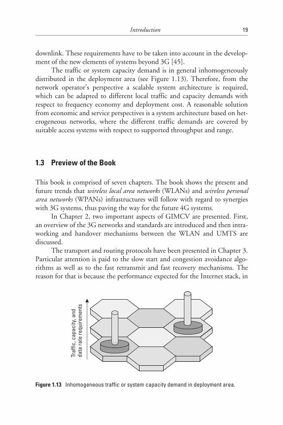
downlink. These requirements have to be taken into account in the develop-ment of the new elements of systems beyond 3G [45].
The traffic or system capacity demand is in general inhomogeneouslydistributed in the deployment area (see Figure 1.13). Therefore, from thenetwork operator’s perspective a scalable system architecture is required,which can be adapted to different local traffic and capacity demands withrespect to frequency economy and deployment cost. A reasonable solutionfrom economic and service perspectives is a system architecture based on het-erogeneous networks, where the different traffic demands are covered bysuitable access systems with respect to supported throughput and range.
1.3 Preview of the Book
This book is comprised of seven chapters. The book shows the present andfuture trends that wireless local area networks (WLANs) and wireless personalarea networks (WPANs) infrastructures will follow with regard to synergieswith 3G systems, thus paving the way for the future 4G systems.
In Chapter 2, two important aspects of GIMCV are presented. First,an overview of the 3G networks and standards are introduced and then intra-working and handover mechanisms between the WLAN and UMTS arediscussed.
The transport and routing protocols have been presented in Chapter 3.Particular attention is paid to the slow start and congestion avoidance algo-rithms as well as to the fast retransmit and fast recovery mechanisms. Thereason for that is because the performance expected for the Internet stack, in
Introduction 19
Figure 1.13 Inhomogeneous traffic or system capacity demand in deployment area.
particular for the TCP, running over these wireless infrastructures is heavilydependent on these algorithms.
Also the IP is presented, focusing mainly on aspects like routing andmobility (both micromobility and macromobility). That is, the ad hoc con-cept and its main challenges, from the perspective of layer three, arepresented.
Chapter 4 is devoted to present the main WLANs specifications. Inparticular the IEEE 802.11 and the HIPERLAN/2 standards are presented.Both the physical (PHY) and the medium access control (MAC) layers aredescribed for the different specifications.
Chapter 5 shows which performances can be expected on the IEEE802.11b platforms when the TCP-UDP/IP protocols run over them. Inparticular, the influence of the wireless errors over the TCP throughput isderived by using a theoretical and practical approach. Also, the UDP proto-col behavior over such platform is shown, based on a measurement cam-paign, and compared with the results obtained by using a theoreticalapproach.
Chapter 6 presents the works in the domain of the WPAN. Bluetoothis chosen as the 1G WPAN and study in depth. Finally, a 2G WPAN per-spective is provided.
In Chapter 7, the performance enhancing proxy (PEP) paradigm is pro-posed as a means to provide internetworking capabilities betweenWLANs/WPANs and increased performances over such platforms. Our per-spective of the future 4G systems based on the collaborative work betweenWLANs/WPANs with 3G systems is justified.
References
[1] Prasad, R., CDMA for Wireless Personal Communications, Norwood, MA: ArtechHouse, 1996.
[2] Prasad, R., Universal Wireless Personal Communications, Norwood, MA: Artech House,1998.
[3] Ojanperä, T., and R. Prasad, (eds.), Wideband CDMA for Third Generation MobileCommunications, Norwood, MA: Artech House, 1998.
[4] van Nee, R., and R. Prasad, OFDM for Wireless Multimedia Communications, Nor-wood, MA: Artech House, 1999.
[5] Prasad, R., W. Mohr, and W. Konhäuser, (eds.), Third-Generation Mobile Communica-tion Systems, Norwood, MA: Artech House, 2000.
20 WLANs and WPANs towards 4G Wireless
[6] Ojanperä, T., and R. Prasad, (eds.), WCDMA: Towards IP Mobility and Mobile Inter-net, Norwood, MA: Artech House, 2000.
[7] Prasad, R., (ed.), Towards a Global 3G System: Advanced Mobile Communications inEurope, Vol. 1, Norwood, MA: Artech House, 2001.
[8] Prasad, R., (ed.), Towards a Global 3G System: Advanced Mobile Communications inEurope, Vol. 2, Norwood, MA: Artech House, 2001.
[9] Farserotu, J., and R. Prasad, IP/ATM Mobile Satellite Networks, Norwood, MA: ArtechHouse, 2001.
[10] Harada, H., and R. Prasad, Simulation and Software Radio for Mobile Communications,Norwood, MA: Artech House, 2002.
[11] Dixit, S., and R. Prasad, (eds.), Wireless IP and Building the Mobile Internet, Norwood,MA: Artech House, 2002.
[12] Calhoun, G., Digital Cellular Radio, Norwood, MA: Artech House, 1988.
[13] Cox, D. C., “Wireless Network Access for Personal Communication,” IEEE Comm.Mag., Vol. 30, December 1992, pp. 96–115.
[14] Padgett, J. E., C. G. Gunther, and T. Hattori, “Overview of Wireless Personal Com-munications,” IEEE Comm. Mag., Vol. 33, January 1995, pp. 28–41.
[15] Kinoshita, K., M. Kuramoto, and N. Nakajima, “Development of a TDMA DigitalCellular System Based on Japanese Standard,” Proc. IEEE VTC’91, 1991, pp. 642–645.
[16] Tuttlebee, W. H. W., (ed.), Cordless Telecommunications in Europe, New York: Sprin-ger Verlag, 1990.
[17] Tuttlebee, W. H. W., “Cordless Personal Communications,” IEEE Comm. Mag., Vol.30, December 1992, pp. 42–62.
[18] Prasad, R., “Wireless Broadband Communication Systems,” IEEE Comm. Mag., Vol.35, January 1997, p. 18.
[19] Honcharenko, W., et al., ‘‘Broadband Wireless Access,” IEEE Comm. Mag., Vol. 35,January 1997, pp. 20–26.
[20] Correia, L. M., and R. Prasad, “An Overview of Wireless Broadband Communica-tions,” IEEE Comm. Mag., Vol. 35, January 1997, pp. 28–33.
[21] Morinaga, N., M. Nakagawa, and R. Kohno, ‘‘New Concepts and Technologies forAchieving Highly Reliable and High Capacity Multimedia Wireless CommunicationsSystem,” IEEE Comm. Mag., Vol. 35, January 1997, pp. 34–40.
[22] da Silva, J. S., et al., “Mobile and Personal Communications: ACTS and Beyond,”Proc. IEEE PIMRC ’97, September 1997.
[23] Priscoli, F.D., and R. Velt, “Design of Medium Access Control and Logical Link Con-trol Functions for ATM Support in the MEDIAN System,” Proc. ACTS Mobile Comm.Summit ’97, October 1997, pp. 734–744.
Introduction 21
[24] Rheinschmitt, R., A. de Haz, and M. Umehinc, “AWACS MAC and LLC Functional-ity,” Proc. ACTS Mobile Comm. Summit ’97, October 1997, pp. 745–750.
[25] Aldid, J., et al., “Magic into Reality, Building the WAND Modem,” Proc. ACTSMobile Comm. Summit ’97, October 1997, pp. 734–744.
[26] Mikkonen, J., et al., “Emerging Wireless Broadband Networks,” IEEE Comm. Mag.,February 1988.
[27] Hase, Y., et al., “R&D Project on Broadband Mobile Communications Using Micro-wave Band,” Proc. MDMC ’96, July 1996, pp. 158–162.
[28] Harada, H., and M. Fujise, “Experimental Performance Analysis of OCDM RadioTransmission System Based on Cyclic Modified M-Sequences for Future IntelligentTransport Systems,” Proc. IEEE VTC’99 Fall, Sept. 1999, pp. 764–767.
[29] Harada, H., and M. Fujise, “Field Experiments of a High Mobility and BroadbandMobile Communication System Based on a New Multicode Transmission Scheme forFuture Intelligent Transport Systems,” Proc. IEEE VTC’2000 Spring, May 1999.
[30] Wu, G., et al., “A Wireless ATM Oriented MAC Protocol for High-Speed WirelessLAN,” Proc. IEEE PIMRC ’97, September 1997, pp. 198–203.
[31] Wu, G., Y. Hase, and M. Inoue, “An ATM-Based Indoor Millimeter-Wave WirelessLAN for Multimedia Transmissions,” IEICE Trans. Commun., Vol. E83-B, No. 8,August 2000, pp. 1740–1752.
[32] Wu, G., K. Mukumoto, and A. Fukuda, “Analysis of an Integrated Voice and DataTransmission System Using Packet Reservation Multiple Access,” IEEE Trans. Veh.Technol., Vol. 43, No. 2, May 1994, pp. 289–297.
[33] Najarian, P. B., ”Status Update on ITS Activities in the U.S. and ITS America,” Proc.ITST2000, October 2000, pp. 7–11.
[34] Ohyama, S., K. Tachikawa, and M. Sato, “DSRC Standards and ETC Systems Devel-opment in Japan,” Proc. 7th World Congress on Intelligent Transport Systems, Torino,Italy, November 2000.
[35] Kim, J. M., “ITS Research and Development Activities at ETRI, Korea,” Proc.ITST2000, October 2000, pp. 13–18.
[36] Armstrong, L., “New DSRC Standards Under Development for North America,” Proc.7th World Congress on Intelligent Transport Systems, Torino, Italy, November 2000.
[37] Rokitansky, C., C. Becker, and Andre Feld, “DSRC Standardisation and ConformanceTesting of DSRC/EFC Equipment,” Proc. 7th World Congress on Intelligent TransportSystems, Torino, Italy, November 2000.
[38] Mohr, W., “Heterogeneous Networks to Support User Needs with Major Challengesfor New Wideband Access Systems,” Int. J. Wireless Personal Communication, SpecialIssue on Unpredictable Future of Wireless Communication.
22 WLANs and WPANs towards 4G Wireless
TEAMFLY
Team-Fly®
[39] Mohr, W., and W. Konhäuser, “Access Network Evolution Beyond Third GenerationMobile Communications,” IEEE Comm. Mag., Vol. 38, No. 12, December 2000, pp.122.
[40] Mohr, W., “Development of Mobile Communications Systems Beyond Third Genera-tion,” Wireless Personal Communications, Vol. 17, No. 2–3, 2001, pp. 191–207.
[41] Hadden, A., “Great Expectations for 3G,” International Telecommunications, July 2001,p. 47.
[42] Analysis Research, 2001.
[43] UMTS/IMT-2000: Assessing Global Requirements for the Next Century, UMTS Forum,Report No. 6, February 1999.
[44] ITU-R, “Report M [IMT.SPEC].”
[45] ITU-R, “Preliminary draft new Recommendation (PDNR): Vision, framework and over-all objectives of the future development of IMT-2000 and of systems beyond IMT-2000,”Status: 7th meeting, 2002, Queenstown, New Zealand, February 27–March 5.
Introduction 23