introduction -...
TRANSCRIPT


1
1. INTRODUCTION
1.1. PROJECT DESRIPTION
This study has been prepared for the Hereford Natural Resource Conservation District (NRCD), who has identified the need for a project which will significantly reduce flooding, erosion and soil loss, as well as road and property damage in and adjacent to Horseshoe Draw (the Project). In order to complete such a project, the Hereford NRCD was awarded a grant from the Arizona Department of Water Resources (ADWR) through the Arizona Water Protection Fund Program. In turn, HILGARTWILSON has been contracted under the Water Protection Fund grant for professional engineering services. This study and corresponding report make up Volume 4 in a series of reports that will be prepared under the awarded grant.
1.2. LOCATION
The study area spans the border between the United States and Mexico roughly 7 miles west of Naco, Arizona/Sonora. The section of the study area located in the US lies within Township 24 South, Range 22 East of the Gila and Salt River Base and Meridian within the Upper San Pedro Basin in Cochise County, Arizona. The Project’s location is highlighted in the Vicinity Map in Figure 1 of Appendix A.
1.3. PURPOSE
This study provides existing conditions groundwater recharge potential analyses which will be used as a baseline comparison for the future recharge potential analysis that will be prepared for the proposed water impoundment structure. The ADWR website states that water level trends in the aquifer of the Upper San Pedro Basin have declined over recent years due to a growing population and increases in water consumption. ADWR also cites that the principle sources of recharge occur through mountain front recharge and beds of ephemeral stream infiltration (ADWR 2014). The proposed impoundment structure will effectively slow the rate of discharge to downstream waters by detaining surface water runoff and subsequently, increase groundwater recharge to the aquifer located within the Upper San Pedro Basin. This study analyzes the volume of stormwater that could potentially recharge the underground aquifer during the theoretical 2-year, 25-year, 50-year, and 100-year storm events through infiltration of the channel bottom. The design of the water impoundment structure is discussed in further detail below. The design flow rates utilized within this study were obtained from the Horseshoe Draw Flood Control, Restoration and Mitigation Study and Design Project Volume 1 – Existing Conditions Hydrologic Study Report (Volume 1) (HILGARTWILSON 2015a) and Volume 2 – Existing Conditions Hydraulic Study Report (Volume 2) (HILGARTWILSON 2015b). The groundwater recharge potential analysis for the Project has been prepared using HEC-HMS version 4.0 with results being compared to a less complex area/infiltration rate volume calculation for validation. The methodology and design parameters used for these analyses are detailed below.

2
2. HYDROLOGIC STUDY OVERVIEW
HEC-HMS was used for the hydrologic analysis of the Project which was detailed within Volume 1 of this report series. Horseshoe Draw conveys runoff from roughly 17 square miles of undeveloped rangeland to the San Pedro River. The watershed of the Project originates in the Sierra San Jose mountains in Mexico and extends to the confluence of Horseshoe Draw and the San Pedro River, located just south of Highway 92. Due to the size of the watershed, both, the 100-year, 6-hour and 100-year, 24-hour storm events were modeled to compare the calculated flow rates. Based on the hydrologic modeling results, the flows determined during the 100-year, 6-hour storm exceeded those determined using the 100-year, 24-hour storm; therefore, the flowrates from the 100-year, 6-hour model have been utilized in this aquifer recharge potential analysis. Subsequently, the 2-year, 25-year, and 50-year flow rates with the 6-hour storm duration were determined using the same methodology outlined in Volume 1.
3. HYDRAULIC STUDY OVERVIEW
Hydraulic analysis for Horseshoe Draw was performed utilizing HEC-RAS version 4.1.0 detailed in Volume 2 of this report series. Cross sections within the model were exported from a digital terrain model (DTM) from AutoCAD Civil 3D. The DTM was built based on a topographic aerial survey performed by Kenny Aerial Mapping, Inc. in October, 2014. The aerial mapping contains detailed topography at 2-foot intervals using the North American Vertical Datum of 1988 (NAVD 88). Channel parameters and cross sections from the HEC-RAS model were referenced for the HEC-HMS model of this report and can be found in Appendix B.
4. GEOTECHNICAL EVALUATION
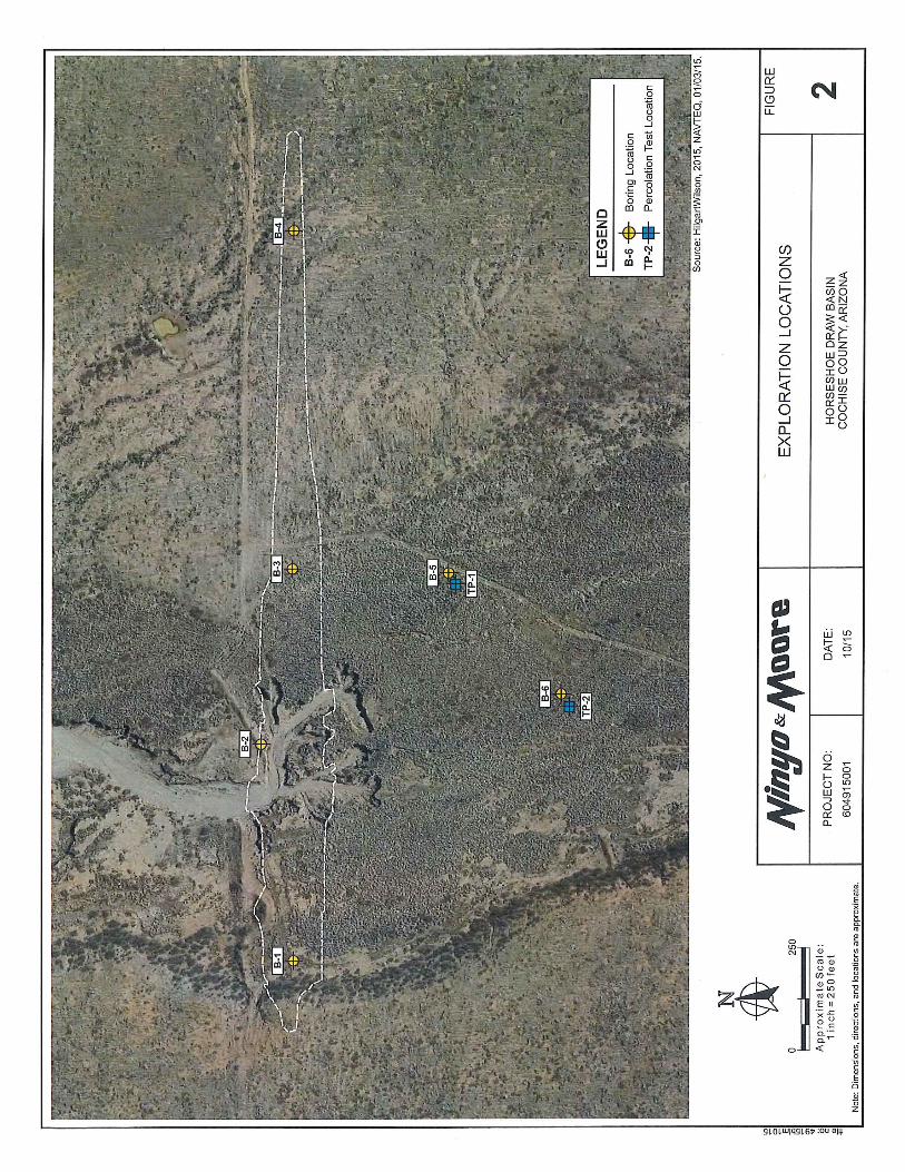
In October 2015, geotechnical analysis for the Project was conducted by Ninyo & Moore, and reported in the Geotechnical Evaluation, Horseshoe Draw Basin (Ninyo & Moore 2015). The purpose of the geotechnical evaluation was to assess the subsurface conditions at the project site in order to provide geotechnical recommendations for design and construction of the impoundment structure. The geotechnical evaluation included shallow field infiltration tests, soil borings, and laboratory testing evaluating the soil properties such as; moisture content, dry density, gradation, and Atterberg limits. The infiltration rates determined within the geotechnical evaluation were used in the methods of estimating recharge volumes. Pertinent excerpts from the geotechnical evaluation report have been included in Appendix C.
5. RECHARGE POTENTIAL MODELING METHODOLOGY
This section describes the methods used in the analysis of the groundwater recharge potential estimate and related data for the study. Hydrologic and hydraulic parameters were referenced from the Volume 1 HEC-HMS model and the Volume 2 HEC-RAS model. Other parameters required for the analysis include a revised routing method for select portions of the basin model network and percolation rate data.

3
5.1. REACH ROUTING
The original Volume 1 hydrologic analysis was accomplished using the Lag routing method and calculated lag time as the sole input parameter with no infiltration losses accounted for. To analyze the effects of percolation, HEC-HMS uses a constant infiltration rate in combination with the inundated area in the reach to compute channel losses. However, the HEC-HMS percolation loss rate parameter is only an option using the modified Puls and Muskingum-Cunge routing methods. Therefore, the main wash routing of Horseshoe Draw was modified to the Muskingum-Cunge method while all other reaches within the HEC-HMS model remained the same. The Muskingum-Cunge method requires channel parameter data including length, slope, Manning’s n, and cross-section geometry for each reach. Representative cross section data was referenced from the Volume 2 HEC-RAS model and are summarized in Table 1 below. The Eight Point channel cross sectional geometry for the four main reaches of Horseshoe Draw can be found in Appendix B. The limits of these four reaches are shown and labeled on Figure 2 of Appendix A.
Table 1: Channel Parameters
Reach Reach Cross-Section Span
Length Slope Manning's n Shape Geometry Method [ft] [ft/ft] Main Sides
R-6 165+20.00-149+31.77 3612 0.006 0.030 0.035 Eight Point R-8 146+92.54-125+56.85 2167 0.017 0.030 0.035 Eight Point R-9 123+29.17-46+95.55 7812 0.009 0.030 0.035 Eight Point
R-12 44+62.68-21+18.63 2405 0.010 0.030 0.035 Eight Point To ensure results from the revised routing method were comparable to the original model, total volumes generated from the 2-year, 25-year, 50-year, and 100-year, storm events were compared for both methods with no infiltration losses modeled. The results were nearly identical which can be seen in Table 2 below.
Table 2: HEC-HMS Routing Method Results Comparison
Reach
Volume [acre-feet] 2-Year 25-Year 50-Year 100-Year
Lag Muskingum-Cunge Lag Muskingum-
Cunge Lag Muskingum-Cunge Lag Muskingum-
Cunge
R-6 112 112 324 324 400 400 483 483 R-8 259 259 774 774 960 960 1163 1164 R-9 261 261 781 781 969 970 1175 1175
R-12 358 358 1078 1078 1339 1339 1624 1624
5.2. PERCOLATION RATE
Percolation rates were tested at two locations during the field geotechnical investigation performed by Ninyo & Moore (2015) detailed in Appendix C. The

4
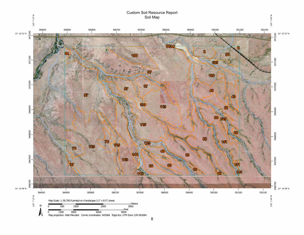
investigation concluded that the test locations near the proposed embankment had an average 0.5-ft3/hr/ft2 (6.1 cubic feet per second (cfs)/acre) percolation rate. Due to limited field data, that average rate was applied throughout all four modified reaches. Supporting the assumption, inspection of the National Resource Conservation Service (NRCS) Soil Resource Map (included as Appendix D) showed that soils throughout the entire Horseshoe Draw wash were consistent to those found at the test locations. To further justify the use of the percolation rate specified by Ninyo and Moore (2015), two journal papers published by the USGS were located through the Upper San Pedro Partnership’s website (www.usppartnership.com) which discuss infiltration rates near the Project and are summarized below. The first paper referenced with reported percolation rates, published in the USGS Professional Paper 1703, titled, Ephemeral-Stream Channel and Basin-Floor Infiltration and Recharge in the Sierra Vista Subwatershed of the Upper San Pedro Basin, Southeastern Arizona (Coes and Pool 2007) found that infiltration rates near the Project ranged from 4.0–32.5 cfs/acre with an average of 32.5 cfs/acre. The second report published in the USGS Scientific Investigations Report 2006-5228 from 2007, titled, Ground-Water Flow Model of the Sierra Vista Subwatershed and Sonoran Portions of the Upper San Pedro Basin, Southeastern Arizona, United States, and Northern Sonora, Mexico (Dickinson and Pool 2007) stated that that infiltration rates near the Project ranged from 4.1–20.7 cfs/acre with an average of 8.2 cfs/acre. The percolation rate used in this report falls on the lower end but within the ranges reported in both papers. Based on the information discussed in this section, it can be assumed that a percolation rate of 6.1 cfs/acre (0.5-ft3/hr/ft2) is reasonable for this Project.
5.3. HEC-HMS MODEL RECHARGE VOLUME ANALYSIS
In order to determine the volume of infiltration for 2-year, 25-year, 50-year, and 100-year storm events, two HEC-HMS scenarios were modeled; 1) without percolation losses which serves as a baseline for the analysis and 2) with percolation losses. The model output returns flow hydrographs in five minute increments over a 23-hour period. The difference between the two flow hydrographs is then used to calculate the total recharge volume into the aquifer.
6. 2-DIMENSIONAL AREA/INFILTRATION CALCULATION
The recharge volumes, determined using HEC-HMS, are based on various parameters and assumptions; therefore, some comparison of results is needed. To calculate the estimated aquifer recharge, inundated floodplain areas and the duration of inundation for the 2-year, 25-year, 50-year, and 100-year storm events are required, used in combination with the established percolation rate of 0.5-ft3/hr/ft2. Floodplain extents have previously been determined in the Volume 2 HEC-RAS analysis (shown in Figure 2) for the various storm events. Floodplain inundation durations are referenced from the HEC-HMS hydrograph outputs of this study. Calculation tables for this method are included in Appendix E.

5
7. RESULTS
The groundwater recharge HEC-HMS model and the area/infiltration calculation parameters used, along with results from the various storm events have been included in Appendix E. Comparison of the HEC-HMS models and the area/infiltration calculations show that the results are similar with an average relative percent difference of 18.5%. This discrepancy can be attributed to the HEC-HMS model being a more robust method that accounts for depth to determine a wetted perimeter which is then combined with the reach length to calculate a total surface area in a given reach. R-12 has a significantly deeper main channel segment compared to upstream channel reaches which is why the discrepancy is more pronounced at smaller storm events. Comparatively, the area/infiltration calculation method uses a 2-dimensional area determined by floodplain limits in AutoCAD yielding smaller volumes of infiltration. Table 3 below summarizes the total volume of infiltration for the given storm events calculated by HEC-HMS. It should be noted that the estimated infiltration calculated occurs at the channel bottom and some, but not all, of the volume will truly be recharged to the aquifer.
Table 3: HEC-HMS Results Summary
Reach Infiltration [acre-feet]
2-Year 25-Year 50-Year 100-Year R-6 50 72 76 80 R-8 90 130 139 147 R-9 119 181 197 235
R-12 124 188 205 245 Total 382 570 618 708
8. CONCLUSION
This study has been prepared in order to provide an existing conditions groundwater recharge potential analysis for Horseshoe Draw using HEC-HMS and will be used as a basis of comparison for future groundwater recharge potential analyses accounting for the proposed water impoundment structure. Since the volumes determined in both the model and the calculation are relatively similar at the given percolation rate, it can be assumed that the volume of groundwater recharge estimated in HEC-HMS will serve as a useful baseline comparison for the future recharge potential analysis. A groundwater recharge potential model with the impoundment structure will be prepared after the managed flow rates leaving the proposed impoundment structure have been determined. The future model will show the beneficial impact that the structure will have on the increased groundwater recharge into the Upper San Pedro Basin.

6
9. REFERENCES
ADWR, (2014). Upper San Pedro Groundwater Conditions. Retrieved December 2, 2015, http://www.azwater.gov/AzDWR/StatewidePlanning/WaterAtlas/SEArizona/Groundwater/UpperSanPedro.htm HILGARTWILSON, (2015a). Horseshoe Draw Flood Control, Restoration and Erosion Mitigation Study and Design Project, Volume 1, Existing Conditions Hydrologic Study. May 2015. Phoenix, Arizona. HILGARTWILSON, (2015b). Horseshoe Draw Flood Control, Restoration and Erosion Mitigation Study and Design Project, Volume 2, Existing Conditions Hydraulic Report. October 2015. Phoenix, Arizona. Ninyo & Moore, (2015). Geotechnical Evaluation Horseshoe Draw Basin. October 2015 Phoenix, Arizona. Pool, D.R., Coes, A.L., (2007). Ephemeral-Stream Channel and Basin-Floor Infiltration and Recharge in the Sierra Vista Subwatershed of the Upper San Pedro Basin, Southeastern Arizona. USGS Professional Paper 1703, Chapter J. Pool, D.R., and Dickinson, J.E., (2007). Ground-Water Flow Model of The Sierra Vista Subwatershed and Sonoran Portions of the Upper San Pedro Basin, Southeastern Arizona. United States and Northern Sonora, Mexico: U.S Geological Survey Scientific Investigations Report 2006-5228. 48 p.

APPENDIX A FIGURES

2141 E. HIGHLAND AVE., STE. 250PHOENIX, AZ 85016
P: 602.490.0535 / F: 602.368.2436

FOX
HO
LLO
W R
OA
DFO
X H
OLL
OW
RO
AD
FOX
HO
LLO
W R
OA
DFO
X H
OLL
OW
RO
AD
FOX
HO
LLO
W R
OA
DFO
X H
OLL
OW
RO
AD
FOX
HO
LLO
W R
OA
DFO
X H
OLL
OW
RO
AD
FOX
HO
LLO
W R
OA
DFO
X H
OLL
OW
RO
AD
FOX
HO
LLO
W R
OA
DFO
X H
OLL
OW
RO
AD
FOX
HO
LLO
W R
OA
DFO
X H
OLL
OW
RO
AD
FOX
HO
LLO
W R
OA
DFO
X H
OLL
OW
RO
AD
FOX
HO
LLO
W R
OA
D
WE
IK R
AN
CH
ES
RO
AD
WE
IK R
AN
CH
ES
RO
AD
WE
IK R
AN
CH
ES
RO
AD
WE
IK R
AN
CH
ES
RO
AD
WE
IK R
AN
CH
ES
RO
AD
WE
IK R
AN
CH
ES
RO
AD
WE
IK R
AN
CH
ES
RO
AD
WE
IK R
AN
CH
ES
RO
AD
WE
IK R
AN
CH
ES
RO
AD
WE
IK R
AN
CH
ES
RO
AD
WE
IK R
AN
CH
ES
RO
AD
WE
IK R
AN
CH
ES
RO
AD
WE
IK R
AN
CH
ES
RO
AD
WE
IK R
AN
CH
ES
RO
AD
WE
IK R
AN
CH
ES
RO
AD
WE
IK R
AN
CH
ES
RO
AD
WE
IK R
AN
CH
ES
RO
AD
PA
LOM
A T
RA
ILP
ALO
MA
TR
AIL
PA
LOM
A T
RA
ILP
ALO
MA
TR
AIL
PA
LOM
A T
RA
ILP
ALO
MA
TR
AIL
PA
LOM
A T
RA
ILP
ALO
MA
TR
AIL
PA
LOM
A T
RA
ILP
ALO
MA
TR
AIL
PA
LOM
A T
RA
ILP
ALO
MA
TR
AIL
PA
LOM
A T
RA
ILP
ALO
MA
TR
AIL
PA
LOM
A T
RA
ILP
ALO
MA
TR
AIL
PA
LOM
A T
RA
IL92
P: 602.490.0535 / F: 602.368.2436www.hilgartwilson.com
2141 E. HIGHLAND AVE., STE. 250PHOENIX, AZ 85016

APPENDIX B REACH AND CHANNEL CROSS SECTIONS

HEC-HMS CHANNEL CROSS SECTIONS

HEC-HMS CROSS-SECTION EIGHT POINT GEOMETRYProject: Horseshoe Draw
Prepared by: HW
Date: Dec 2015
R‐9
R‐12
R‐6
R‐8

HEC-RAS CHANNEL CROSS SECTIONS

0 500 1000 1500 2000 25004390
4395
4400
4405
4410
4415
4420
Horseshoe Draw (Sediment Transport) Plan: Plan 12 11/16/2015
River = HSD Main Channel Reach = HSD Main Channel RS = 16520
Station (ft)
Ele
vatio
n (ft
)
Legend
EG 100-Yr
WS 100-Yr
Crit 100-Yr
Ground
Bank Sta
.035 .03 .035
0 500 1000 1500 2000 25004385
4390
4395
4400
4405
4410
4415
4420
4425
Horseshoe Draw (Sediment Transport) Plan: Plan 12 11/16/2015
River = HSD Main Channel Reach = HSD Main Channel RS = 16246.06
Station (ft)
Ele
vatio
n (ft
)
Legend
EG 100-Yr
WS 100-Yr
Ground
Bank Sta
.035 .03 .035
0 500 1000 1500 2000 25004385
4390
4395
4400
4405
4410
4415
4420
Horseshoe Draw (Sediment Transport) Plan: Plan 12 11/16/2015
River = HSD Main Channel Reach = HSD Main Channel RS = 15946.84
Station (ft)
Ele
vatio
n (ft
)
Legend
EG 100-Yr
WS 100-Yr
Crit 100-Yr
Ground
Bank Sta
.035 .03 .035
0 500 1000 1500 20004380
4385
4390
4395
4400
4405
4410
4415
Horseshoe Draw (Sediment Transport) Plan: Plan 12 11/16/2015
River = HSD Main Channel Reach = HSD Main Channel RS = 15673.03
Station (ft)
Ele
vatio
n (ft
)
Legend
EG 100-Yr
WS 100-Yr
Crit 100-Yr
Ground
Bank Sta
.035 .03 .035
0 500 1000 1500 20004380
4385
4390
4395
4400
4405
4410
4415
Horseshoe Draw (Sediment Transport) Plan: Plan 12 11/16/2015
River = HSD Main Channel Reach = HSD Main Channel RS = 15381.93
Station (ft)
Ele
vatio
n (ft
)
Legend
EG 100-Yr
WS 100-Yr
Crit 100-Yr
Ground
Bank Sta
.035 .03 .035
0 200 400 600 800 1000 1200 1400 16004375
4380
4385
4390
4395
4400
4405
Horseshoe Draw (Sediment Transport) Plan: Plan 12 11/16/2015
River = HSD Main Channel Reach = HSD Main Channel RS = 15141.09
Station (ft)
Ele
vatio
n (ft
)
Legend
EG 100-Yr
WS 100-Yr
Crit 100-Yr
Ground
Bank Sta
.035 .03 .035

0 500 1000 1500 2000 25004375
4380
4385
4390
4395
4400
Horseshoe Draw (Sediment Transport) Plan: Plan 12 11/16/2015
River = HSD Main Channel Reach = HSD Main Channel RS = 14931.77
Station (ft)
Ele
vatio
n (ft
)
Legend
EG 100-Yr
WS 100-Yr
Ground
Bank Sta
.035 .03 .035
0 500 1000 1500 2000 25004375
4380
4385
4390
4395
4400
4405
Horseshoe Draw (Sediment Transport) Plan: Plan 12 11/16/2015
River = HSD Main Channel Reach = HSD Main Channel RS = 14692.54
Station (ft)
Ele
vatio
n (ft
)
Legend
EG 100-Yr
WS 100-Yr
Crit 100-Yr
Ground
Bank Sta
.035 .03 .035
0 500 1000 1500 2000 2500 30004370
4375
4380
4385
4390
4395
4400
Horseshoe Draw (Sediment Transport) Plan: Plan 12 11/16/2015
River = HSD Main Channel Reach = HSD Main Channel RS = 14379.42
Station (ft)
Ele
vatio
n (ft
)
Legend
EG 100-Yr
WS 100-Yr
Crit 100-Yr
Ground
Bank Sta
.035 .03 .035
0 500 1000 1500 2000 2500 30004370
4375
4380
4385
4390
4395
Horseshoe Draw (Sediment Transport) Plan: Plan 12 11/16/2015
River = HSD Main Channel Reach = HSD Main Channel RS = 14066.58
Station (ft)
Ele
vatio
n (ft
)
Legend
EG 100-Yr
WS 100-Yr
Crit 100-Yr
Ground
Bank Sta
.035 .03 .035
0 500 1000 1500 2000 2500 30004365
4370
4375
4380
4385
4390
4395
4400
Horseshoe Draw (Sediment Transport) Plan: Plan 12 11/16/2015
River = HSD Main Channel Reach = HSD Main Channel RS = 13772.72
Station (ft)
Ele
vatio
n (ft
)
Legend
EG 100-Yr
WS 100-Yr
Crit 100-Yr
Ground
Bank Sta
.035 .03 .035
0 500 1000 1500 2000 2500 30004360
4365
4370
4375
4380
4385
4390
4395
Horseshoe Draw (Sediment Transport) Plan: Plan 12 11/16/2015
River = HSD Main Channel Reach = HSD Main Channel RS = 13457.43
Station (ft)
Ele
vatio
n (ft
)
Legend
EG 100-Yr
Crit 100-Yr
WS 100-Yr
Ground
Bank Sta
.035 .03 .035

0 500 1000 1500 2000 2500 30004360
4365
4370
4375
4380
4385
4390
Horseshoe Draw (Sediment Transport) Plan: Plan 12 11/16/2015
River = HSD Main Channel Reach = HSD Main Channel RS = 13130.33
Station (ft)
Ele
vatio
n (ft
)
Legend
EG 100-Yr
WS 100-Yr
Crit 100-Yr
Ground
Bank Sta
.035 .03 .035
0 500 1000 1500 2000 2500 30004355
4360
4365
4370
4375
4380
4385
Horseshoe Draw (Sediment Transport) Plan: Plan 12 11/16/2015
River = HSD Main Channel Reach = HSD Main Channel RS = 12856.26
Station (ft)
Ele
vatio
n (ft
)
Legend
EG 100-Yr
WS 100-Yr
Crit 100-Yr
Ground
Bank Sta
.035 .03 .035
0 500 1000 1500 2000 2500 30004340
4350
4360
4370
4380
4390
Horseshoe Draw (Sediment Transport) Plan: Plan 12 11/16/2015
River = HSD Main Channel Reach = HSD Main Channel RS = 12556.85
Station (ft)
Ele
vatio
n (ft
)
Legend
EG 100-Yr
Crit 100-Yr
WS 100-Yr
Ground
Bank Sta
.035 .03
.035
0 500 1000 1500 2000 2500 30004340
4350
4360
4370
4380
4390
Horseshoe Draw (Sediment Transport) Plan: Plan 12 11/16/2015
River = HSD Main Channel Reach = HSD Main Channel RS = 12329.17
Station (ft)
Ele
vatio
n (ft
)
Legend
EG 100-Yr
WS 100-Yr
Crit 100-Yr
Ground
Levee
Bank Sta
.035 .03
.035
0 500 1000 1500 2000 2500 30004340
4350
4360
4370
4380
4390
Horseshoe Draw (Sediment Transport) Plan: Plan 12 11/16/2015
River = HSD Main Channel Reach = HSD Main Channel RS = 12141.33
Station (ft)
Ele
vatio
n (ft
)
Legend
EG 100-Yr
Crit 100-Yr
WS 100-Yr
Ground
Bank Sta
.035 .03
.035
0 500 1000 1500 2000 2500 30004330
4340
4350
4360
4370
4380
Horseshoe Draw (Sediment Transport) Plan: Plan 12 11/16/2015
River = HSD Main Channel Reach = HSD Main Channel RS = 11917.1
Station (ft)
Ele
vatio
n (ft
)
Legend
EG 100-Yr
WS 100-Yr
Crit 100-Yr
Ground
Levee
Bank Sta
.035 .03
.035

0 500 1000 1500 2000 25004330
4335
4340
4345
4350
4355
4360
4365
4370
4375
Horseshoe Draw (Sediment Transport) Plan: Plan 12 11/16/2015
River = HSD Main Channel Reach = HSD Main Channel RS = 11610.72
Station (ft)
Ele
vatio
n (ft
)
Legend
EG 100-Yr
Crit 100-Yr
WS 100-Yr
Ground
Levee
Bank Sta
.035 .03
.035
0 500 1000 1500 2000 25004330
4335
4340
4345
4350
4355
4360
4365
4370
Horseshoe Draw (Sediment Transport) Plan: Plan 12 11/16/2015
River = HSD Main Channel Reach = HSD Main Channel RS = 11182.79
Station (ft)
Ele
vatio
n (ft
)
Legend
EG 100-Yr
WS 100-Yr
Crit 100-Yr
Ground
Levee
Bank Sta
.035 .03 .035
0 500 1000 1500 2000 25004320
4325
4330
4335
4340
4345
4350
4355
4360
Horseshoe Draw (Sediment Transport) Plan: Plan 12 11/16/2015
River = HSD Main Channel Reach = HSD Main Channel RS = 10592.6
Station (ft)
Ele
vatio
n (ft
)
Legend
EG 100-Yr
WS 100-Yr
Crit 100-Yr
Ground
Levee
Bank Sta
.035 .03
.035
0 500 1000 1500 2000 25004315
4320
4325
4330
4335
4340
4345
4350
4355
4360
Horseshoe Draw (Sediment Transport) Plan: Plan 12 11/16/2015
River = HSD Main Channel Reach = HSD Main Channel RS = 10118.27
Station (ft)
Ele
vatio
n (ft
)
Legend
EG 100-Yr
WS 100-Yr
Crit 100-Yr
Ground
Levee
Bank Sta
.035 .03
.035
0 500 1000 1500 2000 25004310
4315
4320
4325
4330
4335
4340
4345
4350
4355
Horseshoe Draw (Sediment Transport) Plan: Plan 12 11/16/2015
River = HSD Main Channel Reach = HSD Main Channel RS = 9624.29
Station (ft)
Ele
vatio
n (ft
)
Legend
EG 100-Yr
Crit 100-Yr
WS 100-Yr
Ground
Levee
Bank Sta
.035 .03
.035
0 500 1000 1500 2000 2500 30004300
4310
4320
4330
4340
4350
Horseshoe Draw (Sediment Transport) Plan: Plan 12 11/16/2015
River = HSD Main Channel Reach = HSD Main Channel RS = 9149.64
Station (ft)
Ele
vatio
n (ft
)
Legend
EG 100-Yr
Crit 100-Yr
WS 100-Yr
Ground
Levee
Bank Sta
.035 .03 .035

0 500 1000 1500 2000 25004305
4310
4315
4320
4325
4330
4335
4340
4345
Horseshoe Draw (Sediment Transport) Plan: Plan 12 11/16/2015
River = HSD Main Channel Reach = HSD Main Channel RS = 8654.43
Station (ft)
Ele
vatio
n (ft
)
Legend
EG 100-Yr
WS 100-Yr
Crit 100-Yr
Ground
Bank Sta
.035 .03 .035
0 500 1000 1500 2000 2500 30004300
4305
4310
4315
4320
4325
4330
4335
4340
Horseshoe Draw (Sediment Transport) Plan: Plan 12 11/16/2015
River = HSD Main Channel Reach = HSD Main Channel RS = 8227.06
Station (ft)
Ele
vatio
n (ft
)
Legend
EG 100-Yr
WS 100-Yr
Crit 100-Yr
Ground
Bank Sta
.035 .03 .035
0 500 1000 1500 2000 2500 30004290
4300
4310
4320
4330
4340
Horseshoe Draw (Sediment Transport) Plan: Plan 12 11/16/2015
River = HSD Main Channel Reach = HSD Main Channel RS = 7805.03
Station (ft)
Ele
vatio
n (ft
)
Legend
EG 100-Yr
Crit 100-Yr
WS 100-Yr
Ground
Bank Sta
.035 .03
.035
0 500 1000 1500 2000 2500 3000 35004290
4295
4300
4305
4310
4315
4320
4325
4330
Horseshoe Draw (Sediment Transport) Plan: Plan 12 11/16/2015
River = HSD Main Channel Reach = HSD Main Channel RS = 7385.4
Station (ft)
Ele
vatio
n (ft
)
Legend
EG 100-Yr
WS 100-Yr
Crit 100-Yr
Ground
Bank Sta
.035 .03 .035
0 500 1000 1500 2000 2500 30004285
4290
4295
4300
4305
4310
4315
4320
Horseshoe Draw (Sediment Transport) Plan: Plan 12 11/16/2015
River = HSD Main Channel Reach = HSD Main Channel RS = 6964.05
Station (ft)
Ele
vatio
n (ft
)
Legend
EG 100-Yr
Crit 100-Yr
WS 100-Yr
Ground
Bank Sta
.035 .03 .035
0 500 1000 1500 2000 2500 30004280
4285
4290
4295
4300
4305
4310
4315
Horseshoe Draw (Sediment Transport) Plan: Plan 12 11/16/2015
River = HSD Main Channel Reach = HSD Main Channel RS = 6467.25
Station (ft)
Ele
vatio
n (ft
)
Legend
EG 100-Yr
WS 100-Yr
Crit 100-Yr
Ground
Levee
Bank Sta
.035 .03 .035

0 500 1000 1500 2000 2500 30004275
4280
4285
4290
4295
4300
4305
4310
Horseshoe Draw (Sediment Transport) Plan: Plan 12 11/16/2015
River = HSD Main Channel Reach = HSD Main Channel RS = 6090.97
Station (ft)
Ele
vatio
n (ft
)
Legend
EG 100-Yr
WS 100-Yr
Crit 100-Yr
Ground
Levee
Bank Sta
.035 .03 .035
0 500 1000 1500 2000 2500 30004275
4280
4285
4290
4295
4300
4305
Horseshoe Draw (Sediment Transport) Plan: Plan 12 11/16/2015
River = HSD Main Channel Reach = HSD Main Channel RS = 5785.22
Station (ft)
Ele
vatio
n (ft
)
Legend
EG 100-Yr
Crit 100-Yr
WS 100-Yr
Ground
Levee
Bank Sta
.035 .03 .035
0 500 1000 1500 2000 2500 30004270
4275
4280
4285
4290
4295
4300
4305
4310
Horseshoe Draw (Sediment Transport) Plan: Plan 12 11/16/2015
River = HSD Main Channel Reach = HSD Main Channel RS = 5546.66
Station (ft)
Ele
vatio
n (ft
)
Legend
EG 100-Yr
Crit 100-Yr
WS 100-Yr
Ground
Levee
Bank Sta
.035 .03
.035
0 500 1000 1500 2000 25004265
4270
4275
4280
4285
4290
4295
4300
4305
4310
Horseshoe Draw (Sediment Transport) Plan: Plan 12 11/16/2015
River = HSD Main Channel Reach = HSD Main Channel RS = 5283.29
Station (ft)
Ele
vatio
n (ft
)
Legend
EG 100-Yr
WS 100-Yr
Crit 100-Yr
Ground
Levee
Bank Sta
.035 .03 .035
0 500 1000 1500 2000 25004260
4270
4280
4290
4300
4310
4320
Horseshoe Draw (Sediment Transport) Plan: Plan 12 11/16/2015
River = HSD Main Channel Reach = HSD Main Channel RS = 5034.86
Station (ft)
Ele
vatio
n (ft
)
Legend
EG 100-Yr
WS 100-Yr
Crit 100-Yr
Ground
Levee
Bank Sta
.035 .03 .035
0 500 1000 1500 2000 25004260
4270
4280
4290
4300
4310
4320
Horseshoe Draw (Sediment Transport) Plan: Plan 12 11/16/2015
River = HSD Main Channel Reach = HSD Main Channel RS = 4695.55
Station (ft)
Ele
vatio
n (ft
)
Legend
EG 100-Yr
WS 100-Yr
Crit 100-Yr
Ground
Bank Sta
.035
.03 .035

0 500 1000 1500 20004260
4270
4280
4290
4300
4310
Horseshoe Draw (Sediment Transport) Plan: Plan 12 11/16/2015
River = HSD Main Channel Reach = HSD Main Channel RS = 4462.68
Station (ft)
Ele
vatio
n (ft
)
Legend
EG 100-Yr
WS 100-Yr
Ground
Bank Sta
.035 .03 .035
0 200 400 600 800 1000 1200 1400 1600 18004250
4260
4270
4280
4290
4300
4310
Horseshoe Draw (Sediment Transport) Plan: Plan 12 11/16/2015
River = HSD Main Channel Reach = HSD Main Channel RS = 4219.43
Station (ft)
Ele
vatio
n (ft
)
Legend
EG 100-Yr
WS 100-Yr
Ground
Bank Sta
.035 .03 .035
0 200 400 600 800 1000 1200 1400 16004255
4260
4265
4270
4275
4280
4285
4290
4295
Horseshoe Draw (Sediment Transport) Plan: Plan 12 11/16/2015
River = HSD Main Channel Reach = HSD Main Channel RS = 3967.44
Station (ft)
Ele
vatio
n (ft
)
Legend
EG 100-Yr
WS 100-Yr
Crit 100-Yr
Ground
Bank Sta
.035 .03 .035
0 200 400 600 800 1000 1200 1400 16004255
4260
4265
4270
4275
4280
4285
4290
4295
Horseshoe Draw (Sediment Transport) Plan: Plan 12 11/16/2015
River = HSD Main Channel Reach = HSD Main Channel RS = 3674.39
Station (ft)
Ele
vatio
n (ft
)
Legend
EG 100-Yr
WS 100-Yr
Crit 100-Yr
Ground
Bank Sta
.035 .03 .035
0 200 400 600 800 1000 1200 1400 1600 18004250
4260
4270
4280
4290
4300
Horseshoe Draw (Sediment Transport) Plan: Plan 12 11/16/2015
River = HSD Main Channel Reach = HSD Main Channel RS = 3379.1
Station (ft)
Ele
vatio
n (ft
)
Legend
EG 100-Yr
WS 100-Yr
Ground
Bank Sta
.035 .03 .035
0 500 1000 1500 2000 25004250
4255
4260
4265
4270
4275
4280
4285
4290
Horseshoe Draw (Sediment Transport) Plan: Plan 12 11/16/2015
River = HSD Main Channel Reach = HSD Main Channel RS = 3030.67
Station (ft)
Ele
vatio
n (ft
)
Legend
EG 100-Yr
WS 100-Yr
Crit 100-Yr
Ground
Bank Sta
.035 .03 .035

0 500 1000 1500 20004250
4260
4270
4280
4290
4300
Horseshoe Draw (Sediment Transport) Plan: Plan 12 11/16/2015
River = HSD Main Channel Reach = HSD Main Channel RS = 2816.21
Station (ft)
Ele
vatio
n (ft
)
Legend
EG 100-Yr
WS 100-Yr
Crit 100-Yr
Ground
Bank Sta
.035 .03 .035
0 500 1000 1500 20004240
4250
4260
4270
4280
4290
Horseshoe Draw (Sediment Transport) Plan: Plan 12 11/16/2015
River = HSD Main Channel Reach = HSD Main Channel RS = 2587.35
Station (ft)
Ele
vatio
n (ft
)
Legend
EG 100-Yr
WS 100-Yr
Ground
Bank Sta
.035
.03 .035
0 500 1000 1500 20004240
4250
4260
4270
4280
4290
Horseshoe Draw (Sediment Transport) Plan: Plan 12 11/16/2015
River = HSD Main Channel Reach = HSD Main Channel RS = 2350.58
Station (ft)
Ele
vatio
n (ft
)
Legend
EG 100-Yr
WS 100-Yr
Crit 100-Yr
Ground
Bank Sta
.035
.03 .035
0 200 400 600 800 1000 1200 1400 16004240
4250
4260
4270
4280
4290
Horseshoe Draw (Sediment Transport) Plan: Plan 12 11/16/2015
River = HSD Main Channel Reach = HSD Main Channel RS = 2118.63
Station (ft)
Ele
vatio
n (ft
)
Legend
EG 100-Yr
WS 100-Yr
Crit 100-Yr
Ground
Bank Sta
.035 .03
.035
0 200 400 600 800 1000 1200 1400 16004240
4250
4260
4270
4280
4290
Horseshoe Draw (Sediment Transport) Plan: Plan 12 11/16/2015
River = HSD Main Channel Reach = HSD Main Channel RS = 1888.92
Station (ft)
Ele
vatio
n (ft
)
Legend
EG 100-Yr
WS 100-Yr
Crit 100-Yr
Ground
Levee
Bank Sta
.035 .03 .035
0 200 400 600 800 1000 1200 1400 16004230
4240
4250
4260
4270
4280
4290
Horseshoe Draw (Sediment Transport) Plan: Plan 12 11/16/2015
River = HSD Main Channel Reach = HSD Main Channel RS = 1668.12
Station (ft)
Ele
vatio
n (ft
)
Legend
EG 100-Yr
WS 100-Yr
Crit 100-Yr
Ground
Bank Sta
.035 .03
.035

0 200 400 600 800 1000 1200 1400 16004230
4240
4250
4260
4270
4280
4290
Horseshoe Draw (Sediment Transport) Plan: Plan 12 11/16/2015
River = HSD Main Channel Reach = HSD Main Channel RS = 1490.38
Station (ft)
Ele
vatio
n (ft
)
Legend
EG 100-Yr
Crit 100-Yr
WS 100-Yr
Ground
Bank Sta
.035 .03
.035
0 200 400 600 800 1000 1200 14004230
4240
4250
4260
4270
4280
4290
Horseshoe Draw (Sediment Transport) Plan: Plan 12 11/16/2015
River = HSD Main Channel Reach = HSD Main Channel RS = 1255.37
Station (ft)
Ele
vatio
n (ft
)
Legend
EG 100-Yr
WS 100-Yr
Crit 100-Yr
Ground
Bank Sta
.035 .03
.035
0 200 400 600 800 1000 1200 1400 16004230
4240
4250
4260
4270
4280
4290
Horseshoe Draw (Sediment Transport) Plan: Plan 12 11/16/2015
River = HSD Main Channel Reach = HSD Main Channel RS = 1071.27
Station (ft)
Ele
vatio
n (ft
)
Legend
EG 100-Yr
WS 100-Yr
Crit 100-Yr
Ground
Levee
Bank Sta
.035 .03
.035
0 500 1000 1500 2000 25004230
4240
4250
4260
4270
4280
Horseshoe Draw (Sediment Transport) Plan: Plan 12 11/16/2015
River = HSD Main Channel Reach = HSD Main Channel RS = 800.36
Station (ft)
Ele
vatio
n (ft
)
Legend
EG 100-Yr
WS 100-Yr
Crit 100-Yr
Ground
Levee
Bank Sta
.035 .03
.035
0 500 1000 1500 20004225
4230
4235
4240
4245
4250
4255
4260
4265
Horseshoe Draw (Sediment Transport) Plan: Plan 12 11/16/2015
River = HSD Main Channel Reach = HSD Main Channel RS = 623.07
Station (ft)
Ele
vatio
n (ft
)
Legend
EG 100-Yr
WS 100-Yr
Crit 100-Yr
Ground
Levee
Bank Sta
.035 .03
.035
0 200 400 600 800 1000 1200 1400 1600 18004225
4230
4235
4240
4245
4250
4255
4260
4265
Horseshoe Draw (Sediment Transport) Plan: Plan 12 11/16/2015
River = HSD Main Channel Reach = HSD Main Channel RS = 432.97
Station (ft)
Ele
vatio
n (ft
)
Legend
EG 100-Yr
WS 100-Yr
Crit 100-Yr
Ground
Levee
Bank Sta
.035 .03 .035

0 500 1000 1500 20004225
4230
4235
4240
4245
4250
4255
4260
4265
Horseshoe Draw (Sediment Transport) Plan: Plan 12 11/16/2015
River = HSD Main Channel Reach = HSD Main Channel RS = 239.99
Station (ft)
Ele
vatio
n (ft
)
Legend
EG 100-Yr
WS 100-Yr
Crit 100-Yr
Ground
Levee
Bank Sta
.035 .03
.035
0 500 1000 1500 2000 25004225
4230
4235
4240
4245
4250
4255
4260
4265
Horseshoe Draw (Sediment Transport) Plan: Plan 12 11/16/2015
River = HSD Main Channel Reach = HSD Main Channel RS = 20.29
Station (ft)
Ele
vatio
n (ft
)
Legend
EG 100-Yr
WS 100-Yr
Crit 100-Yr
Ground
Levee
Bank Sta
.035 .03
.035

APPENDIX C GEOTECHNICAL EVALUATION EXCERPTS


APPENDIX D NRCS SOIL RESOURCE MAP AND REPORT
8
Custom Soil Resource ReportSoil Map
3466
700
3467
600
3468
500
3469
400
3470
300
3471
200
3472
100
3466
700
3467
600
3468
500
3469
400
3470
300
3471
200
3472
100
584000 584900 585800 586700 587600 588500 589400 590300 591200 592100
584000 584900 585800 586700 587600 588500 589400 590300 591200 592100
31° 22' 51'' N11
0° 7
' 12'
' W31° 22' 51'' N
110°
1' 4
4'' W
31° 19' 49'' N
110°
7' 1
2'' W
31° 19' 49'' N
110°
1' 4
4'' W
N
Map projection: Web Mercator Corner coordinates: WGS84 Edge tics: UTM Zone 12N WGS840 1500 3000 6000 9000
Feet0 500 1000 2000 3000
MetersMap Scale: 1:39,700 if printed on A landscape (11" x 8.5") sheet.

Parent material: Mixed fan alluvium
Typical profileA - 0 to 1 inches: gravelly fine sandy loamBtk - 1 to 8 inches: sandy loamBkm - 8 to 23 inches: cemented materialCk - 23 to 47 inches: extremely cobbly sandy loam2Btkb - 47 to 60 inches: sandy clay loam
Properties and qualitiesSlope: 1 to 10 percentDepth to restrictive feature: 5 to 15 inches to petrocalcicNatural drainage class: Well drainedRunoff class: HighCapacity of the most limiting layer to transmit water (Ksat): Very low to moderately
low (0.00 to 0.06 in/hr)Depth to water table: More than 80 inchesFrequency of flooding: NoneFrequency of ponding: NoneCalcium carbonate, maximum in profile: 30 percentGypsum, maximum in profile: 2 percentSalinity, maximum in profile: Nonsaline (0.0 to 2.0 mmhos/cm)Available water storage in profile: Very low (about 0.9 inches)
Interpretive groupsLand capability classification (irrigated): None specifiedLand capability classification (nonirrigated): 6cHydrologic Soil Group: DEcological site: Limy upland 12-16" p.z. (R041XC309AZ)
125—Riveroad and Ubik soils, 0 to 5 percent slopes
Map Unit SettingNational map unit symbol: 1v7pElevation: 3,900 to 4,600 feetMean annual precipitation: 12 to 16 inchesMean annual air temperature: 60 to 67 degrees FFrost-free period: 180 to 230 daysFarmland classification: Not prime farmland
Map Unit CompositionRiveroad and similar soils: 0 percentUbik and similar soils: 0 percentEstimates are based on observations, descriptions, and transects of the mapunit.
Description of Ubik
SettingLandform: Alluvial fans, flood plainsLandform position (two-dimensional): Summit
Custom Soil Resource Report
28

Landform position (three-dimensional): Tread, dipDown-slope shape: LinearAcross-slope shape: LinearParent material: Mixed alluvium
Typical profileA - 0 to 5 inches: loamC1 - 5 to 16 inches: silt loamC2 - 16 to 60 inches: fine sandy loam
Properties and qualitiesSlope: 0 to 5 percentDepth to restrictive feature: More than 80 inchesNatural drainage class: Well drainedRunoff class: LowCapacity of the most limiting layer to transmit water (Ksat): High (1.98 to 5.95 in/hr)Depth to water table: More than 80 inchesFrequency of flooding: RareFrequency of ponding: NoneCalcium carbonate, maximum in profile: 3 percentGypsum, maximum in profile: 3 percentSalinity, maximum in profile: Nonsaline to very slightly saline (0.0 to 4.0 mmhos/cm)Sodium adsorption ratio, maximum in profile: 4.0Available water storage in profile: Moderate (about 8.0 inches)
Interpretive groupsLand capability classification (irrigated): None specifiedLand capability classification (nonirrigated): 6cHydrologic Soil Group: AEcological site: Loamy swale 12-16" p.z. (R041XC311AZ)
Description of Riveroad
SettingLandform: Alluvial fans, flood plainsLandform position (two-dimensional): SummitLandform position (three-dimensional): Tread, dipDown-slope shape: LinearAcross-slope shape: LinearParent material: Mixed stream alluvium
Typical profileA - 0 to 1 inches: silt loamC1 - 1 to 21 inches: silt loamC2 - 21 to 60 inches: silty clay loam
Properties and qualitiesSlope: 0 to 5 percentDepth to restrictive feature: More than 80 inchesNatural drainage class: Well drainedRunoff class: LowCapacity of the most limiting layer to transmit water (Ksat): Moderately high (0.20
to 0.57 in/hr)Depth to water table: More than 80 inchesFrequency of flooding: RareFrequency of ponding: NoneCalcium carbonate, maximum in profile: 5 percent
Custom Soil Resource Report
29

Gypsum, maximum in profile: 4 percentSalinity, maximum in profile: Nonsaline (0.0 to 2.0 mmhos/cm)Available water storage in profile: High (about 11.2 inches)
Interpretive groupsLand capability classification (irrigated): None specifiedLand capability classification (nonirrigated): 6cHydrologic Soil Group: CEcological site: Loamy bottom 12-16" p.z. (R041XC312AZ)
139—Tenneco fine sandy loam, 0 to 2 percent slopes
Map Unit SettingNational map unit symbol: 1v7kElevation: 3,800 to 4,700 feetMean annual precipitation: 12 to 16 inchesMean annual air temperature: 60 to 67 degrees FFrost-free period: 180 to 230 daysFarmland classification: Prime farmland if irrigated
Map Unit CompositionTenneco and similar soils: 80 percentEstimates are based on observations, descriptions, and transects of the mapunit.
Description of Tenneco
SettingLandform: Flood plains, alluvial fansLandform position (two-dimensional): SummitLandform position (three-dimensional): Tread, dipDown-slope shape: LinearAcross-slope shape: LinearParent material: Mixed fan alluvium
Typical profileA - 0 to 2 inches: fine sandy loamBw - 2 to 11 inches: sandy clay loamBk - 11 to 41 inches: loamC - 41 to 60 inches: sandy loam
Properties and qualitiesSlope: 0 to 2 percentDepth to restrictive feature: More than 80 inchesNatural drainage class: Well drainedRunoff class: LowCapacity of the most limiting layer to transmit water (Ksat): Moderately high to high
(0.20 to 1.98 in/hr)Depth to water table: More than 80 inchesFrequency of flooding: RareFrequency of ponding: NoneCalcium carbonate, maximum in profile: 15 percent
Custom Soil Resource Report
30

Salinity, maximum in profile: Nonsaline (0.0 to 2.0 mmhos/cm)Available water storage in profile: Moderate (about 8.6 inches)
Interpretive groupsLand capability classification (irrigated): 2eLand capability classification (nonirrigated): 6cHydrologic Soil Group: BEcological site: Loamy swale 12-16" p.z. (R041XC311AZ)
144—Ubik complex, 0 to 3 percent slopes
Map Unit SettingNational map unit symbol: 1v71Elevation: 3,900 to 4,600 feetMean annual precipitation: 12 to 16 inchesMean annual air temperature: 60 to 67 degrees FFrost-free period: 180 to 230 daysFarmland classification: Not prime farmland
Map Unit CompositionUbik, silt loam, and similar soils: 50 percentUbik, fine sandy loam, and similar soils: 30 percentEstimates are based on observations, descriptions, and transects of the mapunit.
Description of Ubik, Silt Loam
SettingLandform: Flood plains, alluvial fansLandform position (two-dimensional): SummitLandform position (three-dimensional): Tread, dipDown-slope shape: LinearAcross-slope shape: LinearParent material: Mixed alluvium
Typical profileC1 - 0 to 10 inches: silt loamC2 - 10 to 32 inches: loamC3 - 32 to 60 inches: fine sandy loam
Properties and qualitiesSlope: 0 to 3 percentDepth to restrictive feature: More than 80 inchesNatural drainage class: Well drainedRunoff class: LowCapacity of the most limiting layer to transmit water (Ksat): Moderately high to high
(0.57 to 1.98 in/hr)Depth to water table: More than 80 inchesFrequency of flooding: OccasionalFrequency of ponding: NoneCalcium carbonate, maximum in profile: 5 percentGypsum, maximum in profile: 3 percentSodium adsorption ratio, maximum in profile: 13.0
Custom Soil Resource Report
31

APPENDIX E HEC-HMS AND AREA/INFILTRATION CALCULATION RESULTS AND
COMPARISON

GROUNDWATER RECHARGE POTENTIAL RESULTS COMPARISONProject: Horseshoe Draw
Prepared by: HW
Date: Dec 2015
Volume Total Volume Volume Total Volume[ft2] [hrs] [acre‐feet] [acre‐feet] [acre‐feet] [acre‐feet]
R‐6 526,512 9.3 56 50
R‐8 730,204 10.2 85 90
R‐9 869,649 10.3 103 119
R‐12 107,155 10.5 13 124
R‐6 640,173 10.7 78 72
R‐8 906,996 11.4 119 130
R‐9 1,634,605 11.5 216 181
R‐12 347,699 11.6 46 188
R‐6 665,638 10.9 83 76
R‐8 1,080,093 11.7 145 139
R‐9 1,779,495 11.8 240 197
R‐12 1,027,385 11.8 140 205
R‐6 690,882 11.2 89 80
R‐8 1,150,561 11.8 156 147
R‐9 1,890,104 11.9 259 235
R‐12 1,480,716 12.1 205 245
Notes:
Percolation rate (i) = 0.5 ft3/hr/ft2
Calculation Volume = (A)*(i)*(t)
709 708
2‐Year
25‐Year
50‐Year
100‐Year
618
459
608
570
Storm EventHEC‐HMS
Reach
382
Floodplain Area [A]
Inudation Duration [t]
Area/Infiltration
258

Horseshoe Draw HEC-HMS Model Flow Output
0
500
1000
1500
2000
0:00 3:00 6:00 9:00 12:00 15:00 18:00 21:00 0:00
Flow
(cfs)
Time (hh:mm)
Flow HydrographReach 6, 2‐Year
R‐6 No Percolation
R‐6 With Percolation
Difference in hydrographsrepresents volumetric loss due to infiltration/ shallow recharge.
0
500
1000
1500
2000
0:00 3:00 6:00 9:00 12:00 15:00 18:00 21:00 0:00
Flow
(cfs)
Time (hh:mm)
Flow HydrographReach 8, 2‐Year
R‐8 No Percolation
R‐8 With Percolation

Horseshoe Draw HEC-HMS Model Flow Output
0
500
1000
1500
2000
0:00 3:00 6:00 9:00 12:00 15:00 18:00 21:00 0:00
Flow
(cfs)
Time (hh:mm)
Flow HydrographReach 9, 2‐Year
R‐9 No Percolation
R‐9 With Percolation
0
500
1000
1500
2000
0:00 3:00 6:00 9:00 12:00 15:00 18:00 21:00 0:00
Flow
(cfs)
Time (hh:mm)
Flow HydrographReach 12, 2‐Year
R‐12 No Percolation
R‐12 With Percolation

Horseshoe Draw HEC-HMS Model Flow Output
0
1000
2000
3000
4000
5000
0:00 3:00 6:00 9:00 12:00 15:00 18:00 21:00 0:00
Flow
(cfs)
Time (hh:mm)
Flow HydrographReach 6, 25‐Year
R‐6 No Percolation
R‐6 With Percolation
0
1000
2000
3000
4000
5000
0:00 3:00 6:00 9:00 12:00 15:00 18:00 21:00 0:00
Flow
(cfs)
Time (hh:mm)
Flow HydrographReach 8, 25‐Year
R‐8 No Percolation
R‐8 With Percolation

Horseshoe Draw HEC-HMS Model Flow Output
0
1000
2000
3000
4000
5000
0:00 3:00 6:00 9:00 12:00 15:00 18:00 21:00 0:00
Flow
(cfs)
Time (hh:mm)
Flow HydrographReach 9, 25‐Year
R‐9 No Percolation
R‐9 With Percolation
0
1000
2000
3000
4000
5000
0:00 3:00 6:00 9:00 12:00 15:00 18:00 21:00 0:00
Flow
(cfs)
Time (hh:mm)
Flow HydrographReach 12, 25‐Year
R‐12 No Percolation
R‐12 With Percolation

Horseshoe Draw HEC-HMS Model Flow Output
0
1000
2000
3000
4000
5000
6000
0:00 3:00 6:00 9:00 12:00 15:00 18:00 21:00 0:00
Flow
(cfs)
Time (hh:mm)
Flow HydrographReach 6, 50‐Year
R‐6 No Percolation
R‐6 With Percolation
0
1000
2000
3000
4000
5000
6000
0:00 3:00 6:00 9:00 12:00 15:00 18:00 21:00 0:00
Flow
(cfs)
Time (hh:mm)
Flow HydrographReach 8, 50‐Year
R‐8 No Percolation
R‐8 With Percolation

Horseshoe Draw HEC-HMS Model Flow Output
0
1000
2000
3000
4000
5000
6000
0:00 3:00 6:00 9:00 12:00 15:00 18:00 21:00 0:00
Flow
(cfs)
Time (hh:mm)
Flow HydrographReach 9, 50‐Year
R‐9 No Percolation
R‐9 With Percolation
0
1000
2000
3000
4000
5000
6000
0:00 3:00 6:00 9:00 12:00 15:00 18:00 21:00 0:00
Flow
(cfs)
Time (hh:mm)
Flow HydrographReach 12, 50‐Year
R‐12 No Percolation
R‐12 With Percolation

Horseshoe Draw HEC-HMS Model Flow Output
0
1000
2000
3000
4000
5000
6000
7000
0:00 3:00 6:00 9:00 12:00 15:00 18:00 21:00 0:00
Flow
(cfs)
Time (hh:mm)
Flow HydrographReach 6, 100‐Year
R‐6 No Percolation
R‐6 With Percolation
0
1000
2000
3000
4000
5000
6000
7000
0:00 3:00 6:00 9:00 12:00 15:00 18:00 21:00 0:00
Flow
(cfs)
Time (hh:mm)
Flow HydrographReach 8, 100‐Year
R‐8 No Percolation
R‐8 With Percolation

Horseshoe Draw HEC-HMS Model Flow Output
0
1000
2000
3000
4000
5000
6000
7000
0:00 3:00 6:00 9:00 12:00 15:00 18:00 21:00 0:00
Flow
(cfs)
Time (hh:mm)
Flow HydrographReach 9, 100‐Year
R‐9 No Percolation
R‐9 With Percolation
0
1000
2000
3000
4000
5000
6000
7000
0:00 3:00 6:00 9:00 12:00 15:00 18:00 21:00 0:00
Flow
(cfs)
Time (hh:mm)
Flow HydrographReach 12, 100‐Year
R‐12 No Percolation
R‐12 With Percolation