introduction into simulation cfd for the turbomachinery
TRANSCRIPT
Join the conversation #AU2017Join the conversation #AULondon
Introduction into Simulation CFD for the Turbomachinery applicationsAmal Cheikh rouhou
Technical Support Specialist, M.SC in Mechanical Engineering

Join the conversation #AU2017Join the conversation #AULondon
Introduction into Simulation CFD for the Turbomachinery applicationsAmal Cheikh rouhou
Technical Support Specialist, M.SC in Mechanical Engineering
Make sure to download the Handout detailing the Model Setup under:
https://autodesk.app.box.com/v/CFD

1. Understand how CFD impacts the design process
2. Gain exposure to the Autodesk Simulation CFD interface and
simulation workflow
3. Learn how to use the powerful post-processing tools to interpret
simulation results and to make decisions
4. Discover CFD best practices and pitfalls in Turbomachinery
Key learning objectives

Impact of Simulation CFD on the design process
Simulation CFD for Turbomachinery
Exercise: Centrifugal pumps in Simulation CFD
Questions & Answers
Agenda

Impact of Simulation CFD on the design process

PrototypingTesting
Final CADManual
calculationFirst CADConcept
Traditional Design processFail
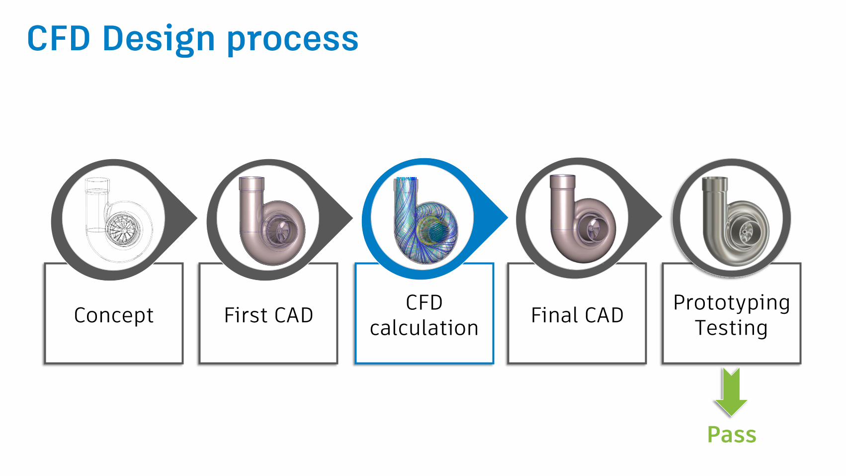
Final CADCFD
calculationFirst CADConcept
PrototypingTesting
CFD Design process
Pass
Simulation CFD for Turbomachinery

Performance prediction
Visualization of flow features
Energy loss calculation
Design validation & optimization
CFD benefits for Turbomachinery
Exercise: Centrifugal pumps in Simulation CFD

Impeller:
Rotating device
Has blades fixed on a hub plate
Volute/Casing:
Static device
Increasing cross sectional area
Centrifugal pump: What is it?

1. Impeller rotates (Electric motor)
2. It creates low pressure at the inlet
3. The low pressure helps suck fluid
4. The fluid is pushed radially from
the impeller to the volute
Centrifugal pump: How does it work?

Centrifugal pump: How does it work?

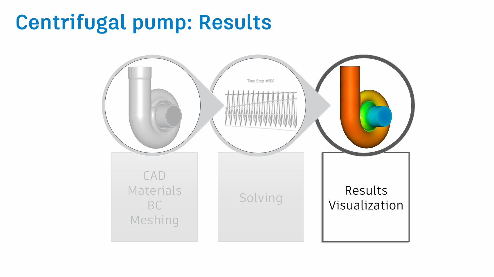
SolvingResults
Validation
CADMaterials
BCMeshing
CFD Workflow - Steps

Centrifugal pump: The CAD Model
SolvingResults
Validation
CADMaterials
BCMeshing

Simplifications
Remove the shaft from the
impeller
Fill in small gaps
Remove radii
Remove useless features
Centrifugal pump: The CAD Model
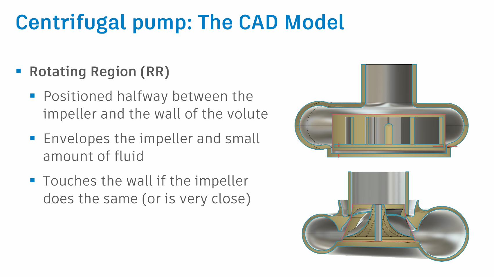
Rotating Region (RR)
Positioned halfway between the
impeller and the wall of the volute
Envelopes the impeller and small
amount of fluid
Touches the wall if the impeller
does the same (or is very close)
Centrifugal pump: The CAD Model

Openings extension
Extend inlet and outlet
Inlet = 5X diameter in length
Outlet = 10X diameter in length
Centrifugal pump: The CAD Model

SolvingResults
Validation
CADMaterials
BCMeshing
Centrifugal pump: Model Setup (Live Demo)

Things to avoid
Rotating region material
The impulsive start-up: When the full rotational speed is specified
from the beginning
Boundary conditions (BC)
Direct application of non-zero pressure or flow rate at the discharge
Meshing
Defining a non-adequate mesh. Rotating region analyses can be
especially mesh sensitive

Tips & Tricks: Meshing
Use the adequate wall layers settings that give:
Nodal Aspect Ratio < 100
Wall distance Y+ ~ 1 (SST k-w)

Tips & Tricks: Meshing
Make sure to have a uniform mesh over the rotating region
hotspots
Convergence instability
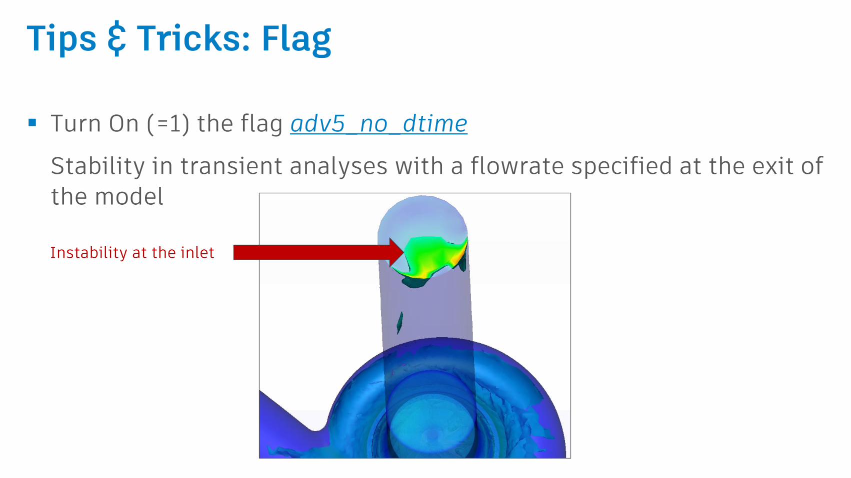
Tips & Tricks: Flag
Turn On (=1) the flag adv5_no_dtime
Stability in transient analyses with a flowrate specified at the exit of
the model
Instability at the inlet
CADMaterials
BCMeshing
SolvingResults
Visualization
Centrifugal pump: Results

Centrifugal pump: Convergence assessment
The convergence plot from a good Rotating region analysis will
look as follows (Global results)

Centrifugal pump: Convergence assessment
Convergence can be assessed using:
The global results of pressure
Rotating Region results: Plot of
the hydraulic torque
Monitor Points to track
convergence of variables at
specific points
-0.35
-0.3
-0.25
-0.2
-0.15
-0.1
-0.05
0
0 1 2 3 4 5 6
Hy
dra
uli
c T
orq
ue
[N
.m]
Time [sec]
Torque Curve

Centrifugal pump: Results visualization
The bulk-calculator tool
calculates values of variables of
interest over cut-planes
The data extracted from the bulk
calculator over the openings of
the model + Hydraulic torque
data help evaluate the pump
efficiency

Centrifugal pump: Result visualization
Cut Planes show high levels of
detail – vectors are especially
useful
ISO Surfaces are useful for finding
regions of interest
Highest flow
Cavitation
Nodal Aspect Ratio

Centrifugal pump: Result visualization
Iso Surfaces
Cut-planes with vectors

Troubleshooting
Accuracy
Verify that the geometry represents the actual geometry
Extend the openings when needed (avoid re-circulation)
Verify that the analysis settings (pressure, RPM, fluid) match test
conditions
Refine the mesh throughout the model, and reduce time step size
Verify that torque, pressure, and flow have reached a steady-state
solution (stopped changing). If not, run additional time steps

Questions & Answers

Autodesk and the Autodesk logo are registered trademarks or trademarks of Autodesk, Inc., and/or its subsidiaries and/or affiliates in the USA and/or other countries. All other brand names, product names, or trademarks belong to their respective holders. Autodesk reserves the right to alter product and services offerings, and specifications and pricing at any time without notice, and is not responsible for typographical or graphical errors that may appear in this document.
© 2017 Autodesk. All rights reserved.