introduction. introduction and basic concept what is verilog? –hardware description language(hdl)...
Post on 21-Dec-2015
224 views
TRANSCRIPT

IntroductionIntroduction


Introduction and Basic ConceptIntroduction and Basic Concept
• What is Verilog?–Hardware Description Language(HDL)
• Why use Verilog?–Because 60% of US companies use it.

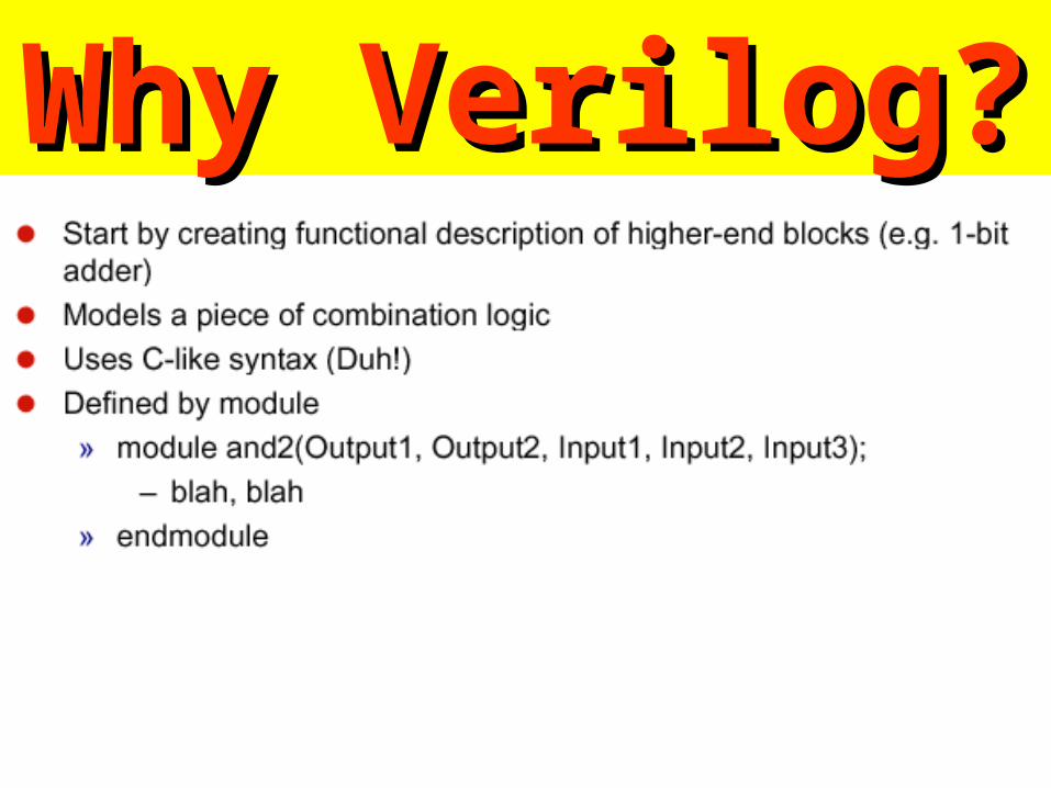
Why Verilog?Why Verilog?• Why use an HDL?
– Describe complex designs (millions of gates)
– Input to synthesis tools (synthesizable subset)
– Design exploration with simulation
• Why not use a general purpose language– Support for structure and instantiation
– Support for describing bit-level behavior
– Support for timing
– Support for concurrency
• Verilog vs. VHDL– Verilog is relatively simple and close to C
– VHDL is complex and close to Ada
– Verilog has 60% of the world digital design market (larger share in US)

Why Verilog?Why Verilog?
Why Verilog?Why Verilog?

Verilog HDL and Verilog-XLVerilog HDL and Verilog-XL
• Verilog HDL– Hardware design language that allows you to
design circuit.
• Verilog-XL– High speed, event-driven simulator that reads
Verilog HDL and simulates the behavior of hardware.

Synthesis
Place and Route
clb 1clb 2
Always inst1 inst2 inst3
Modern Project MethodologyModern Project Methodology
mapping

Introduction to Introduction to Verilog onlyVerilog only
• Objectives– Understand the design methodologiesmethodologies using Verilog
• Target audience– have basic digital circuits design concept– knowledge of VHDL for design of digital systems– Verilog description for logic synthesis
• NOT in the talk– a full coverage of Verilog

ContentsContents• Verilog HDL
– structured modeling– RTL modeling
• Example combinational circuits– structured description (net-list)– RTL
• Example sequential circuits– RTL
• FSM– combinational circuits– sequential circuits

Verilog history Verilog history • Gateway Design Automation
– Phil Moorby in 1984 and 1985
• Verilog-XL, "XL algorithm", 1986– a very efficient method for doing gate-level simulation
• Verilog logic synthesizer, Synopsys, 1988– the top-down design methodology is feasible
• Cadence Design Systems acquired Gateway– December 1989
– a proprietary HDL

• Open Verilog International (OVI), 1991– Language Reference Manual (LRM)– making the language specification as vendor-
independent as possible.
• The IEEE 1364 working group, 1994– to turn the OVI LRM into an IEEE standard.
• Verilog became an IEEE standard – December, 1995.
Verilog history Verilog history

Hardware Description LanguagesHardware Description Languages
• The functionality of hardware– concurrency– timing controls
• The implementation of hardware– structure– net-list
• ISP – C. Gordon Bell and Alan Newell at Carnegie Mellon
University, 1972– RTL (register transfer level)

Different Levels of AbstractionDifferent Levels of Abstraction
• Algorithmic– the function of the system
• RTL– the data flow– the control signals– the storage element and clock
• Gate– gate-level net-list
• Switch – transistor-level net-list

Verilog for Digital System DesignVerilog for Digital System Design
• Structural description– net-list using primitive gates and switches
– continuous assignment using Verilog operators
• RTL– functional description
– timing controls and concurrency specification
– procedural blocks (always and initial)
– registers and latches
• C + timing controls + concurrency

Verilog Procedural Verilog Procedural DescriptionsDescriptions

Verilog VariablesVerilog Variables
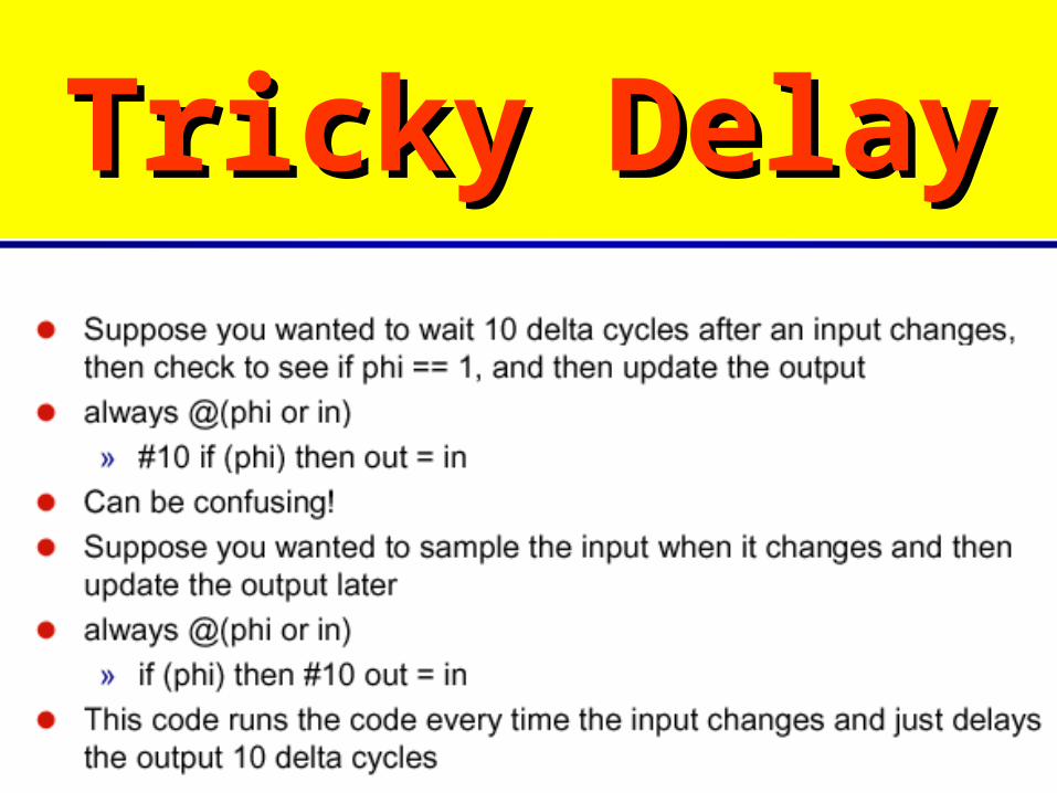
Tricky DelayTricky Delay

Initial BlockInitial Block

Verilog Usage Verilog Usage

Different StatesDifferent States

Procedural Procedural StatementsStatements

Still a Problem?Still a Problem?
Hierarchical structure and Hierarchical structure and Modules Modules
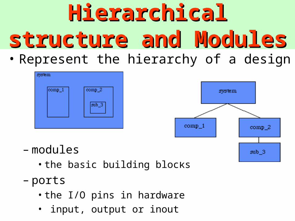
• Represent the hierarchy of a design
– modules• the basic building blocks
– ports • the I/O pins in hardware
• input, output or inout
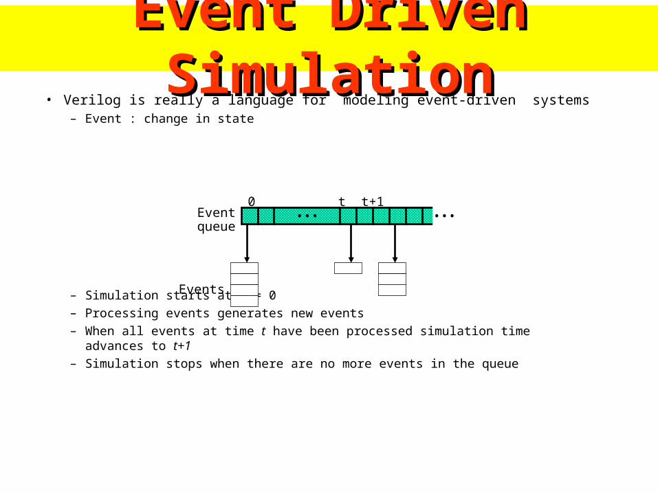
Event Driven SimulationEvent Driven Simulation• Verilog is really a language for modeling event-driven systems
– Event : change in state
– Simulation starts at t = 0– Processing events generates new events– When all events at time t have been processed simulation time advances to t+1– Simulation stops when there are no more events in the queue
•••0 t t+1
•••Eventqueue
Events
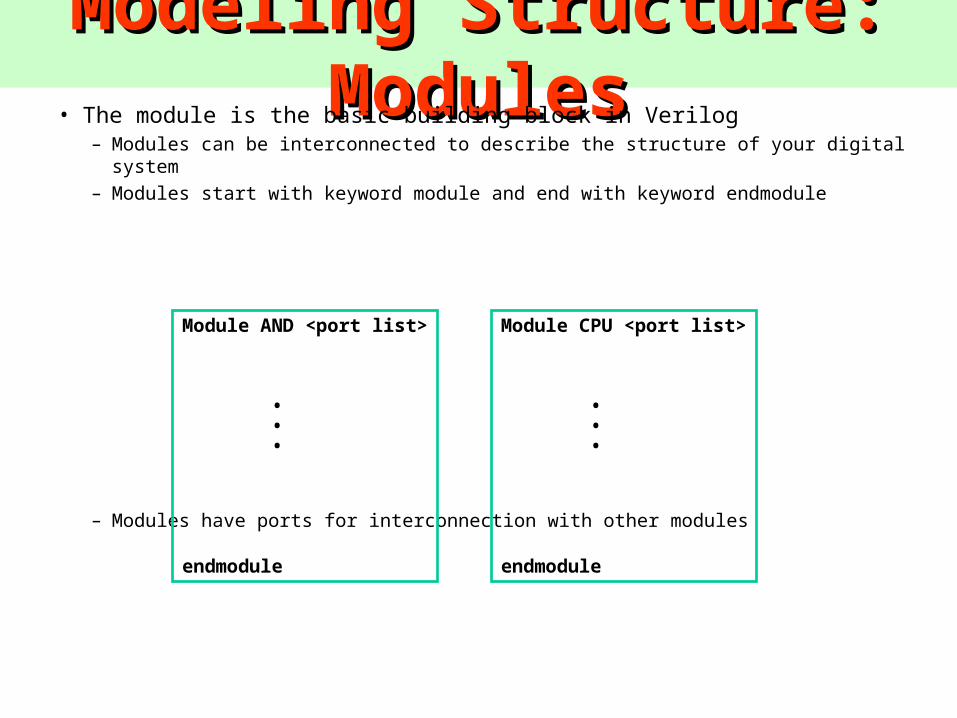
Modeling Structure: ModulesModeling Structure: Modules• The module is the basic building block in Verilog
– Modules can be interconnected to describe the structure of your digital system– Modules start with keyword module and end with keyword endmodule
– Modules have ports for interconnection with other modules
Module AND <port list>
• • •
endmodule
Module CPU <port list>
• • •
endmodule

Modeling Structure: PortsModeling Structure: Ports• Module Ports
– Similar to pins on a chip
– Provide a way to communicate with outside world
– Ports can be input, output or inout
i0
i1
o
Module AND (i0, i1, o);input i0, i1;output o;
endmodule
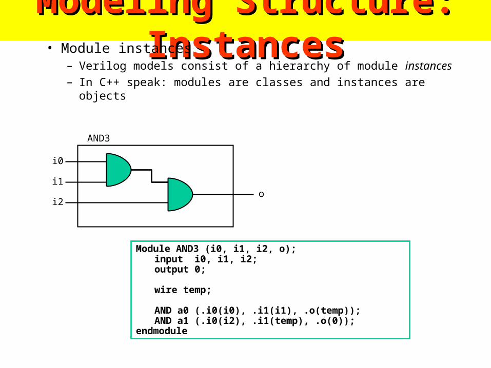
Modeling Structure: InstancesModeling Structure: Instances• Module instances
– Verilog models consist of a hierarchy of module instances
– In C++ speak: modules are classes and instances are objects
AND3
i0
i1
i2o
Module AND3 (i0, i1, i2, o);input i0, i1, i2;output 0;
wire temp;
AND a0 (.i0(i0), .i1(i1), .o(temp));AND a1 (.i0(i2), .i1(temp), .o(0));
endmodule
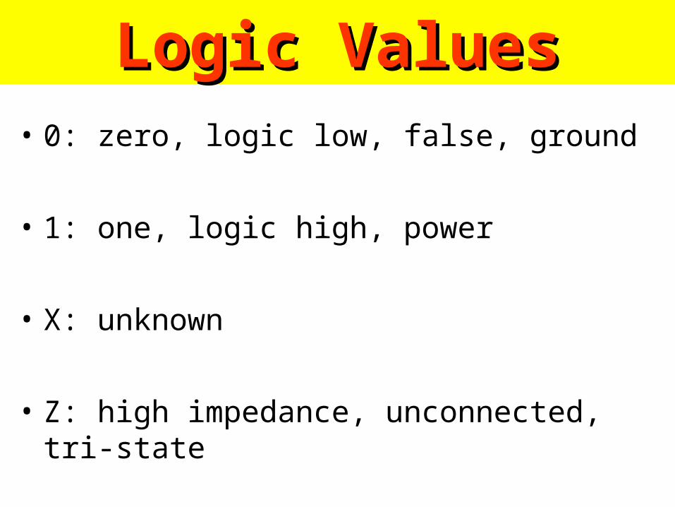
Logic ValuesLogic Values• 0: zero, logic low, false, ground
• 1: one, logic high, power
• X: unknown
• Z: high impedance, unconnected, tri-state

Data TypesData Types• Nets
– Nets are physical connections between devices– Nets always reflect the logic value of the driving device– Many types of nets, but all we care about is wire
• Registers– Implicit storage – unless variable of this type is
modified it retains previously assigned value– Does not necessarily imply a hardware register– Register type is denoted by reg
- int is also used

Variable DeclarationVariable Declaration• Declaring a net
wire [<range>] <net_name> [<net_name>*];Range is specified as [MSb:LSb]. Default is one bit wide
• Declaring a registerreg [<range>] <reg_name> [<reg_name>*];
• Declaring memoryreg [<range>] <memory_name> [<start_addr> :
<end_addr>];
• Examplesreg r; // 1-bit reg variablewire w1, w2; // 2 1-bit wire variablereg [7:0] vreg; // 8-bit registerreg [7:0] memory [0:1023]; a 1 KB memory

Ports and Data TypesPorts and Data Types• Correct data types for ports
inout
input outputnet net
net
net
Register/net register/net
Module
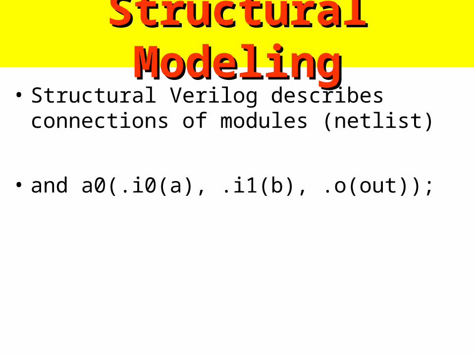
Structural ModelingStructural Modeling• Structural Verilog describes connections of
modules (netlist)
• and a0(.i0(a), .i1(b), .o(out));
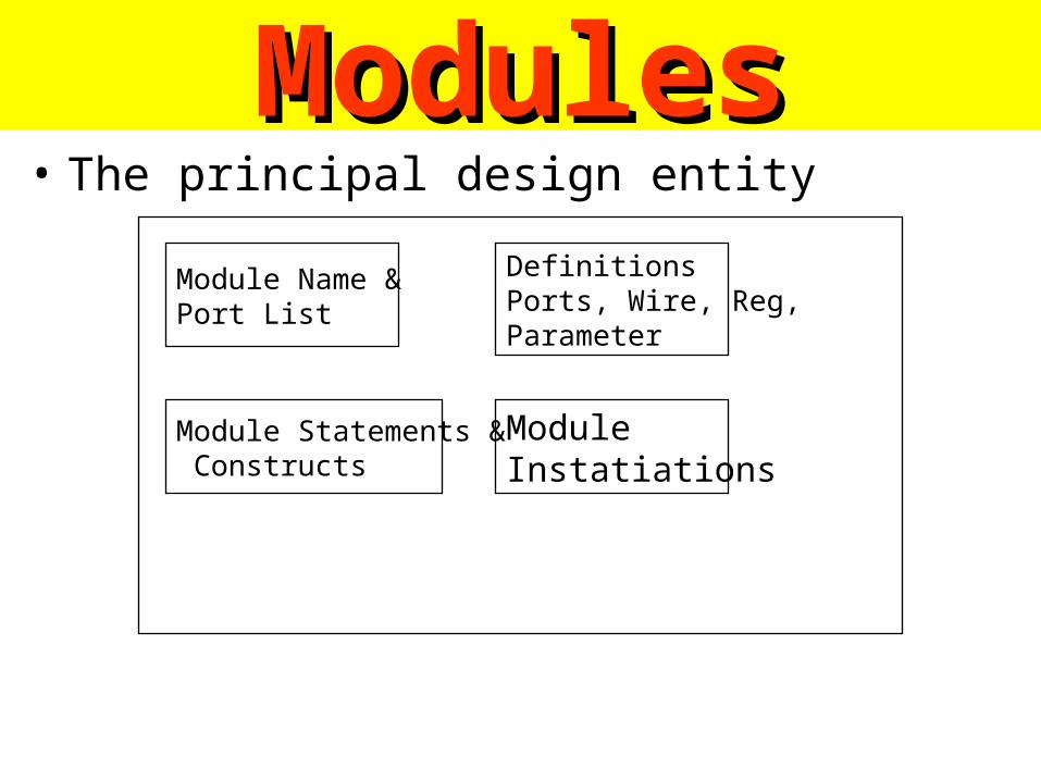
ModulesModules• The principal design entity
Module Name &Port List
DefinitionsPorts, Wire, Reg,Parameter
ModuleInstatiations
Module Statements & Constructs

ExampleExample• 4-bit adder
module add4 (s,c3,ci,a,b)
input [3:0] a,b ; // port declarations
input ci ;
output [3:0] s : // vector
output c3 ;
wire [2:0] co ;add a0 (co[0], s[0], a[0], b[0], ci) ;
add a1 (co[1], s[1], a[1], b[1], co[0]) ;
add a2 (co[2], s[2], a[2], b[2], co[1]) ;
add a3 (c3, s[3], a[3], b[3], co[2]) ;
endmodulea0a1a2a3c3 ci
Simpler than VHDL
Only Syntactical Difference

Data types Data types • Net
– physical wire between devices
– the default data type
– used in structural modeling and continuous assignment
– types of nets• wire, tri : default
• wor, trior : wire-ORed
• wand, triand : wire-ANDed
• trireg : with capacitive storage
• tri1 : pull high
• tri0 ; pull low
• supply1 ; power
• supply0 ; ground
Simpler than VHDL
Only Syntactical Difference

Verilog SimulatorVerilog Simulator
Circuit Description
Testfixture
Verilog Simulator
Simulation Result
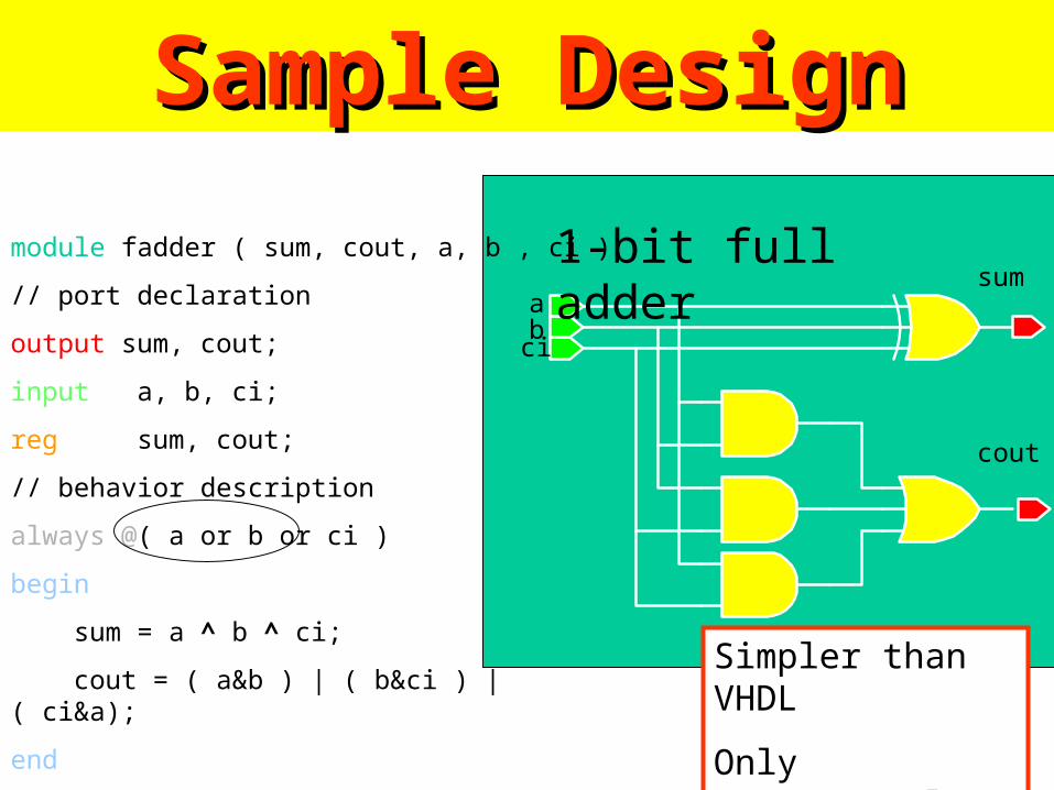
Sample DesignSample Design
module fadder ( sum, cout, a, b , ci );
// port declaration
output sum, cout;
input a, b, ci;
reg sum, cout;
// behavior description
always @( a or b or ci )
begin
sum = a ^ b ^ ci;
cout = ( a&b ) | ( b&ci ) | ( ci&a);
end
endmodule
1-bit full adderab
ci
sum
cout
Simpler than VHDL
Only Syntactical Difference

Basic Basic InstructionsInstructions

Lexical Conventions in Lexical Conventions in VerilogVerilog
Type of lexical tokens :•Operators ( * )
•White space
•Comment
•Number ( * )
•String
•Identifier
•Keyword ( * ) Note : * will be discussed

Reg and ParametersReg and Parameters• Reg
– variables used in RTL description– a wire, a storage device or a temporary variable– reg : unsigned integer variables of varying bit width
– integer : 32-bit signed integer
– real : signed floating-point
– time : 64-bit unsigned integer
• Parameters– run-time constants
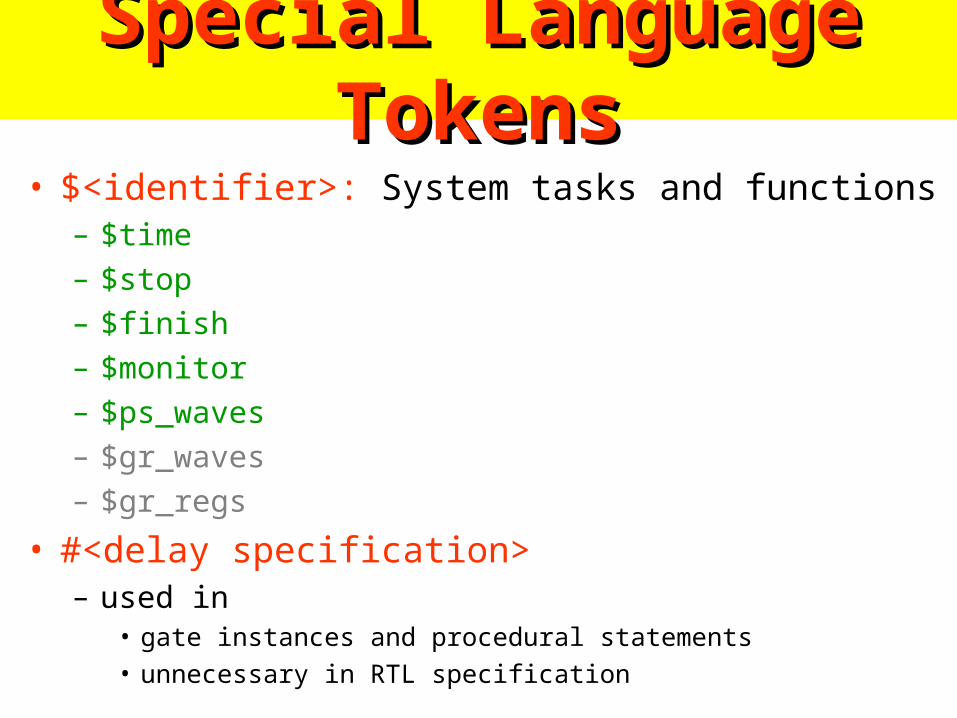
Special Language TokensSpecial Language Tokens• $<identifier>: System tasks and functions
– $time
– $stop
– $finish
– $monitor
– $ps_waves
– $gr_waves
– $gr_regs
• #<delay specification>– used in
• gate instances and procedural statements
• unnecessary in RTL specification

Modeling Structures Modeling Structures • Net-list
– structural description for the top level
• Continuous assignments (combination circuits)– data flow specification for simple combinational
– Verilog operators
• Procedural blocks (RTL)– always and initial blocks
• allow timing control and concurrency
– C-like procedure statements
• primitives (=truth table, state transition table)• function and task (function and subroutine)

A full-adderA full-adder• module add (co, s, a, b, c)
input a, b ,c ;
output co, s ;xor (n1, a, b) ;
xor (s, n1, c) ;
nand (n2, a, b) ;
nand (n3,n1, c) ;
nand (co, n3,n2) ;
endmodule
Simpler than VHDL
Only Syntactical Difference

Verilog PrimitivesVerilog Primitives• Basic logic gates only
– and– or– not– buf– xor– nand– nor– xnor– bufif1, bufif0– notif1, notif0

Primitive Pins Are ExpandablePrimitive Pins Are Expandable
• One output and variable number of inputs
• not and buf – variable number of outputs but only one input
nand (y, in1, in2) ;
nand (y, in1, in2, in3) ;
nand (y, in1, in2, in3, in4) ;

Continuous AssignmentsContinuous Assignments• Describe combinational logic
• Operands + operators
• Drive values to a net– assign out = a&b ; // and gate– assign eq = (a==b) ; // comparator– wire #10 inv = ~in ; // inverter with delay– wire [7:0] c = a+b ; // 8-bit adder
• Avoid logic loops– assign a = b + a ;– asynchronous design

Logical and Conditional OperatorsLogical and Conditional Operators
• Logical, bit-wise and unary operatorsa = 1011; b = 0010
logical bit-wise unary
a || b = 1 a | b = 1011 |a = 1
a && b = 1 a &b = 0010 &a = 0
• Conditional operatorassign z = ({s1,s0} == 2'b00) ? IA :
({s1,s0} == 2'b01) ? IB :
({s1,s0} == 2'b10) ? IC :
({s1,s0} == 2'b11) ? ID :
1'bx ;
assign s = (op == ADD) ? a+b : a-b ;

OperatorsOperators
{}Concatenations
?:Conditional Operators
>>, <<Shift Operators
&, ~&, |, ~|, ^, ~^Unary Reduction
~, &, |, ^, ~^Bit-Wise Operators
!, &&, ||Logical Operators
==, !=, ===, !==Equality Operators
<, <=, >, >=Relational Operators
+, -, *, /, %Arithmetic Operators

Operator PrecedenceOperator Precedence[ ] bit-select or
part-select
( ) parentheses
!, ~ logical and bit-wise negation
&, |, ~&, ~|, ^, ~^, ^~reduction operators
+, - unary arithmetic
{ } concatenation
*, /, % arithmetic
+, - arithmetic
<<, >> shift
>, >=, <, <=
relational
==, != logical equality
& bit-wise AND
^, ^~, ~^
bit-wise XOR and XNOR
| bit-wise OR
&& logical AND
|| logical OR
? : conditional
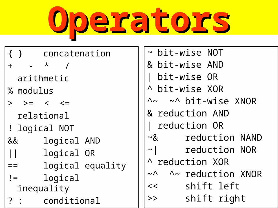
OperatorsOperators{ } concatenation
+ - * /
arithmetic
% modulus
> >= < <=
relational
! logical NOT
&& logical AND
|| logical OR
== logical equality
!= logical inequality
? : conditional
~ bit-wise NOT& bit-wise AND| bit-wise OR^ bit-wise XOR^~ ~^ bit-wise XNOR& reduction AND| reduction OR~& reduction NAND~| reduction NOR^ reduction XOR~^ ^~ reduction XNOR<< shift left>> shift right

NumbersNumbersFormat : <size>’<base><value>
Example : 8’d16
8’h10
8’b00010000
8’o20

KeywordsKeywordsNote : All keywords are defined in lower case
Examples : module, endmodule
input, output, inout
reg, integer, real, time
not, and, nand, or, nor, xor
parameter
begin, end
fork, join
specify, endspecify

Value Set in VerilogValue Set in Verilog
‘0’
‘1’
‘X’
‘Z’0
4-value logic system in Verilog :
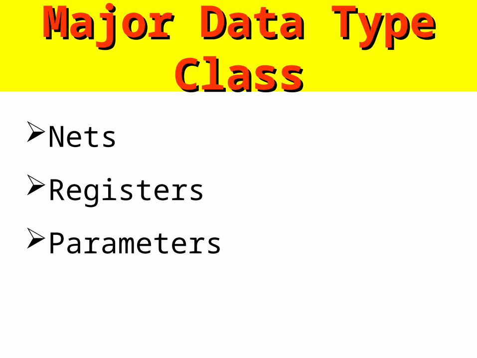
Major Data Type ClassMajor Data Type Class
Nets
Registers
Parameters

NetsNetsNet data type represent physical connections between structural entities.
A net must be driven by a driver, such as a gate or a continuous assignment.
Verilog automatically propagates new values onto a net when the drivers change value.

Registers & ParametersRegisters & ParametersRegisters represent abstract storage elements.
A register holds its value until a new value is assigned to it.
Registers are used extensively in behavior modeling and in applying stimuli.
Parameters are not variables, they are constants.

AssignmentsAssignmentsAssignment : drive values into nets and registers.
Continuous Assignments – Any changes in the RHS of continuous assignment are evaluated and the LHS is update.
Example : (1) assign out = ~in;
(2) assign reg_out; = reg_in << shift

Assignments ( cont. )Assignments ( cont. )
Blocking procedural assignment.
rega = regb + regc;
Non-blocking procedural assignment.
rega <= regb * regc;

RTL RTL ModelingModeling
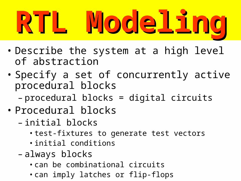
RTL ModelingRTL Modeling• Describe the system at a high level of abstraction• Specify a set of concurrently active procedural
blocks– procedural blocks = digital circuits
• Procedural blocks– initial blocks
• test-fixtures to generate test vectors• initial conditions
– always blocks• can be combinational circuits• can imply latches or flip-flops

Procedural blocks have the following Procedural blocks have the following componentscomponents
• procedural assignment statements
• timing controls
• high-level programming language constructs
initial cc statementc …c …c …c …c …
always cc statementc …c …c …c …c …

RTL StatementsRTL Statements– Procedural and RTL assignments
• reg & integer• out = a + b ;
– begin . . . end block statements• group statements
– if. . . else statements– case statements– for loops– while loops– forever loops– disable statements
• disable a named block

Combinational Always BlocksCombinational Always Blocks
• A complete sensitivity list (inputs)always @(a or b or c)
f = a&~c | b&c ;
• Simulation resultsalways @(a or b)
f = a&~c | b&c ;
• Parenthesesalways @(a or b or c or d)
z = a + b + c + d ; // z = (a+b) + (c+d) ;

Sequential Always BlocksSequential Always Blocks• Inferred latches (Incomplete branch specifications)
module infer_latch(D, enable, Q); input D, enable; output Q; reg Q; always @ (D or enable) begin if (enable) Q <= D; endendmodule
– the Q is not specified in a branch• a latch like 74373

Combinational Circuit DesignCombinational Circuit Design• Outputs are functions of inputs
• Examples– MUX– decoder– priority encoder– adder
comb.circuits
inputs Outputs

MultiplexorMultiplexor• Net-list (gate-level)
module mux2_1 (out,a,b,sel) ;
output out ;
input a,b,sel ;
not (sel_, sel) ;
and (a1, a, sel_) ;
and (b1, b, sel) ;
or (out, a1, b1) ;
endmodule

MultiplexorMultiplexor• Continuous assignment
module mux2_1 (out,a,b,sel) ;
output out ;
input a,b,sel ;
assign out = (a&~sel)|(b&sel) ;
endmodule
• RTL modelingalways @(a or b or sel)
if(sel)out = b;
elseout = a;

MultiplexorMultiplexor• 4-to-1 multiplexor
module mux4_1 (out, in0, in1, in2, in3, sel) ;
output out ;
input in0,in1,in2,in3 ;
input [1:0] sel ;
assign out = (sel == 2'b00) ? in0 :
(sel == 2'b01) ? in1 :
(sel == 2'b10) ? in2 :
(sel == 2'b11) ? in3 :
1'bx ;
endmodule

module mux4_1 (out, in, sel) ; output out ; input [3:0] in ; input [1:0] sel ; reg out ; always @(sel or in) begin
case(sel) 2’d0: out = in[0] ; 2’d1: out = in[1] ; 2’d2: out = in[2] ; 2’d3: out = in[3] ; default: 1’bx ; endcaseend
endmodule
out = in[sel] ;
MultiplexorMultiplexor

DecoderDecoder• 3-to 8 decoder with an
enable controlmodule decoder(o,enb_,sel) ;
output [7:0] o ;
input enb_ ;
input [2:0] sel ;
reg [7:0] o ;
always @ (enb_ or sel)
if(enb_)
o = 8'b1111_1111 ;
else
case(sel)
3'b000 : o = 8'b1111_1110 ;
3'b001 : o = 8'b1111_1101 ;
3'b010 : o = 8'b1111_1011 ;
3'b011 : o = 8'b1111_0111 ;
3'b100 : o = 8'b1110_1111 ;
3'b101 : o = 8'b1101_1111 ;
3'b110 : o = 8'b1011_1111 ;
3'b111 : o = 8'b0111_1111 ;
default : o = 8'bx ;
endcase
endmodule

Priority EncoderPriority Encoderalways @ (d0 or d1 or d2 or d3)
if (d3 == 1){x,y,v} = 3’b111 ;
else if (d2 == 1){x,y,v} = 3’b101 ;
else if (d1 == 1){x,y,v} = 3’b011 ;
else if (d0 == 1){x,y,v} = 3’b001 ;
else{x,y,v} = 3’bxx0 ;

Parity CheckerParity Checkermodule parity_chk(data, parity);
input [0:7] data;
output parity;
reg parity;
always @ (data)
begin: check_parity
reg partial;
integer n;
partial = data[0];
for ( n = 0; n <= 7; n = n + 1)
begin
partial = partial ^ data[n];
end
parity <= partial;
end
endmodule

AdderAdder• RTL modeling
module adder(c,s,a,b) ;
output c ;
output [7:0] s ;
input [7:0] a,b ;
assign {c,s} = a + b ;
endmodule
• Logic synthesis– CLA adder for speed optimization– ripple adder for area optimization

Tri-StateTri-State• The value z
always @ (sela or a)if (sela)
out = a ;
elseout = 1’bz ;
• Another blockalways @(selb or b)
if(selb)out =b ;
elseout = 1’bz ;
assign out = (sela)? a: 1’bz ;

Registers (Flip-flops) are impliedRegisters (Flip-flops) are implied
–@(posedge clk) or @(negedge clk)
–a positive edge-triggered D flip-flopalways @ (posedge clk)
q = d ;

Procedural AssignmentsProcedural Assignments
• Blocking assignments always @(posedge clk) begin
rega = data ;
regb = rega ;
end
• Non-blocking assignmentsalways @(posedge clk) begin
regc <= data ;
regd <= regc ;
end

Sequential Sequential Circuit Circuit DesignDesign

Sequential Circuit DesignSequential Circuit Design
– a feedback path
– the state of the sequential circuits
– the state transition synchronous circuits asynchronous circuits
Memoryelements
Combinationalcircuit
Inputs Outputs

Finite State MachineFinite State Machine• Moore model
• Mealy model
comb.circuit
inputs memoryelements
nextstate comb.
circuitoutputs
currentstate
comb.circuit
inputs memoryelements
nextstate comb.
circuitoutputs
currentstate
ExamplesExamples– D flip-flop– D latch– register– shifter– counter– pipeline– FSM
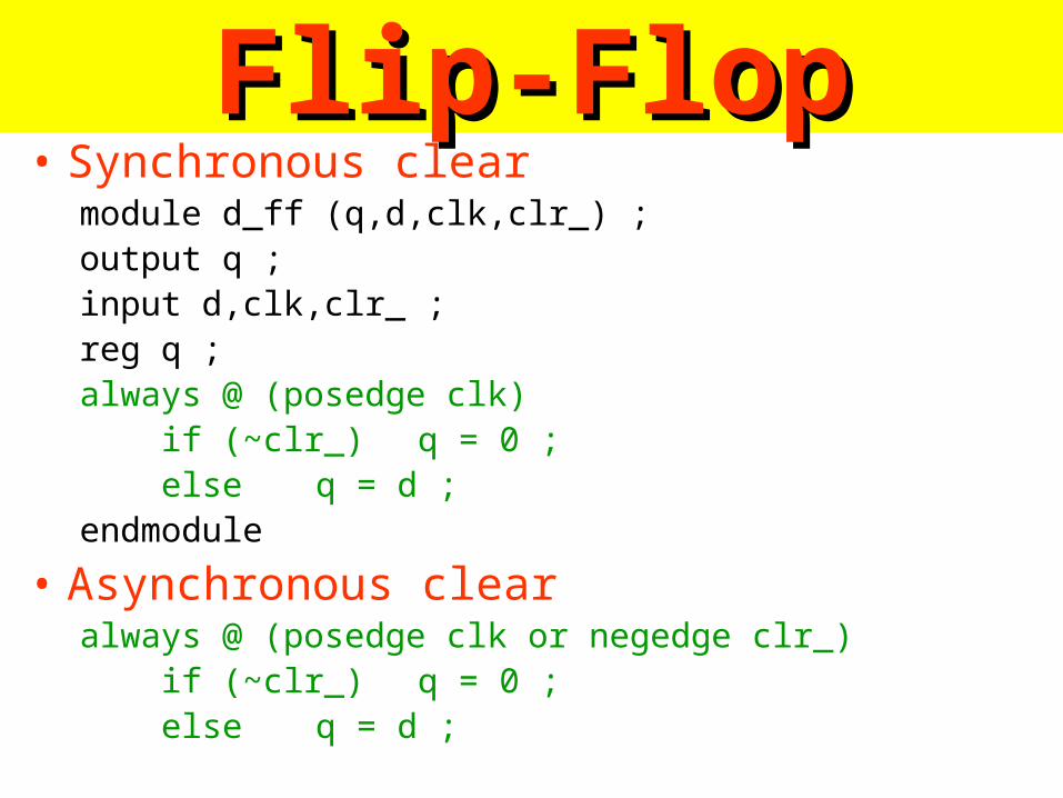
Flip-FlopFlip-Flop• Synchronous clear
module d_ff (q,d,clk,clr_) ;output q ;input d,clk,clr_ ;reg q ;always @ (posedge clk) if (~clr_) q = 0 ; else q = d ;endmodule
• Asynchronous clearalways @ (posedge clk or negedge clr_) if (~clr_) q = 0 ; else q = d ;

RegisterRegistermodule register (q,d,clk,clr_, set_) ;
output [7:0] q ;
input [7:0] d ;
input clk,clr_, set_ ;
reg [7:0] q ;
always @ (posedge clk or negedge clr_ or negedge set_)
if (~clr_)
q = 0 ;
else if (~set_)
q = 8’b1111_1111 ;
else
q = d ;
endmodule

D LatchesD Latches• D latch
always @ (enable or data)
if (enable)
q = data ;
• D latch with gated asynchronous dataalways @ (enable or data or gate)
if (enable)
q = data & gate ;

• D latch with gated ‘enable’always @ (enable or d or gate)
if (enable & gate)
q = d ;
• D latch with asynchronous resetalways @ (reset or data or gate)
if (reset)
q = 1’b0
else if(enable)
q = data ;
D LatchesD Latches
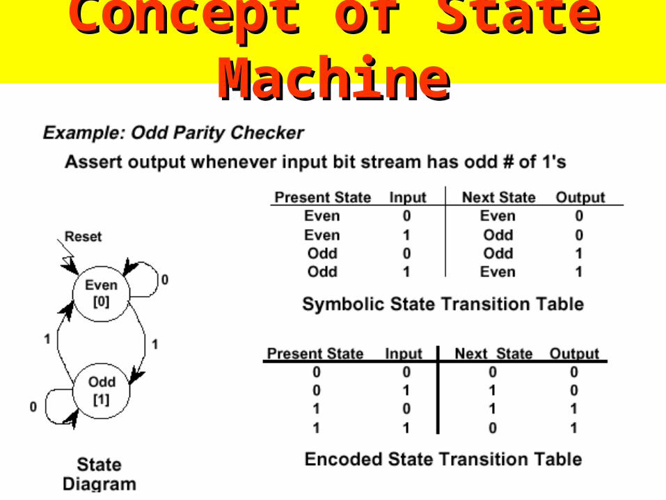
Concept of State MachineConcept of State Machine

Concept of FSM in VerilogConcept of FSM in Verilog

Vending Machine ExampleVending Machine Example

Parity Checker ExampleParity Checker Example

ShifterShiftermodule shifter (so,si,d,clk,ld_,clr_) ;output so ;input [7:0] d ;input si,clk,ld_,clr_ ; // asynchronous clear and synchronous loadreg [7:0] q ;assign so = q[7] ;always @ (posedge clk or negedge clr_) if (~clr_)
q = 0 ; else if (~ld_)
q = d ; else
q[7:0] = {q[6:0],si} ;endmodule
shifterso
clk
si
dld_

CounterCountermodule bcd_counter(count,ripple_out,clr,clk) ;output [3:0] count ;output ripple_out ;reg [3:0] count ;input clr,clk ;wire ripple_out = (count == 4'b1001) ? 0:1 ; // combinationalalways @ (posedge clk or posedge clr) // combinational + sequential
if (clr) ;count = 0 ;
else if (count == 4'b1001)count = 0 ;
elsecount = count + 1 ;
endmodule

MemoryMemorymodule memory (data, addr, read, write);
input read, write;
input [4:0] addr;
inout [7:0] data;
reg [7:0] data_reg;
reg [7:0] memory [0:8'hff];
parameter load_file = "cput1.txt";
assign data = (read) ? memory [addr] : 8'hz;
always @ (posedge write)
memory[addr] = data;
initial
$readmemb (load_file, memory);
endmodule

Inefficient DescriptionInefficient Descriptionmodule count (clock, reset, and_bits, or_bits, xor_bits);input clock, reset;output and_bits, or_bits, xor_bits;reg and_bits, or_bits, xor_bits;reg [2:0] count; always @(posedge clock) begin
if (reset) count = 0;
else count = count + 1; and_bits = & count; or_bits = | count; xor_bits = ^ count;
endendmodule
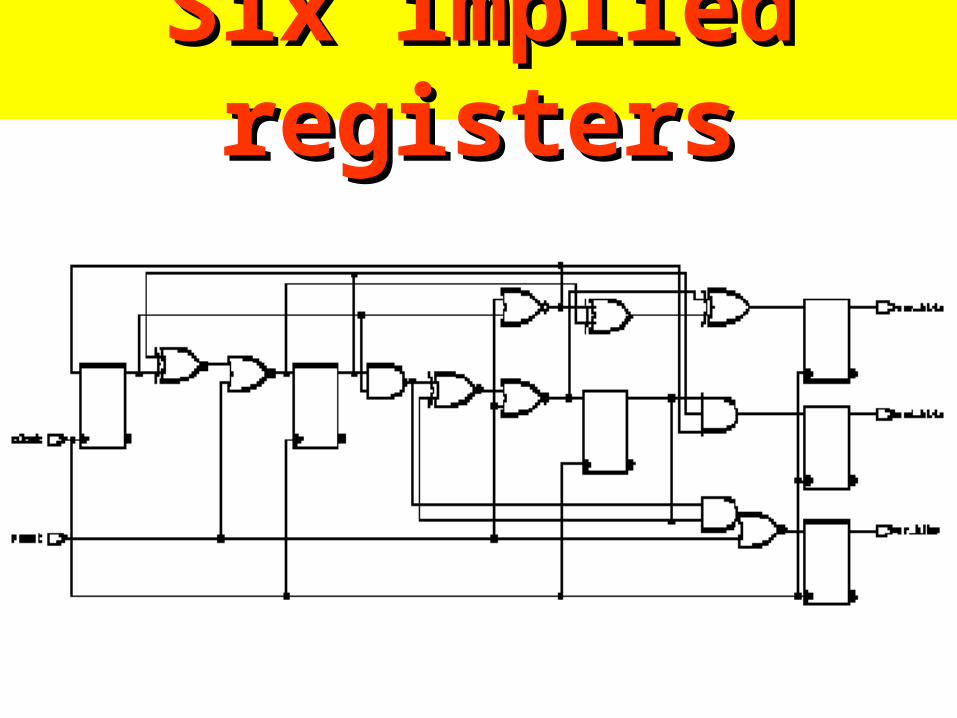
Six implied registersSix implied registers

Efficient DescriptionEfficient Descriptionmodule count (clock, reset,
and_bits, or_bits, xor_bits);input clock, reset;output and_bits, or_bits, xor_bits;reg and_bits, or_bits, xor_bits;reg [2:0] count;always @(posedge clock) begin
if (reset) count = 0;else count = count + 1;
end
// combinational circuitsalways @(count) begin
and_bits = & count;or_bits = | count;xor_bits = ^ count;
endendmodule
Separate combinational and sequential circuitsSeparate combinational and sequential circuits

Three registers are usedThree registers are used

Mealy Machine ExampleMealy Machine Examplemodule mealy (in1, in2, clk, reset,out);input in1, in2, clk, reset;output out;reg current_state, next_state, out;// state flip-flops always @(posedge clk or negedge
reset) if (!reset)
current_state = 0; else
current_state = next_state;// combinational: next-state and outputsalways @(in1 or in2 or current_state) case (current_state)
0: beginnext_state = 1;out = 1'b0;
end1: if (in1) begin
next_state = 1'b0;out = in2;
end else begin
next_state = 1'b1;out = !in2;
end endcaseendmodule

PipelinesPipelines
• An example
assign n_sum = a+bassign p = sum * d_c// plus D flip-flopsalways @ (posedge clk)
sum = n_sum ;
flip-flops
comb.circuits
flip-flops
comb.circuits
flip-flops
comb.circuits
Dff
Dff
Dff
a
b
c
out
n-sumsum
d_c
p

Traffic Light Controller
Picture of Highway/Farmroad Intersection:
Highway
Highway
Farmroad
Farmroad
HL
HL
FL
FL
C
C
A FSM ExampleA FSM Example
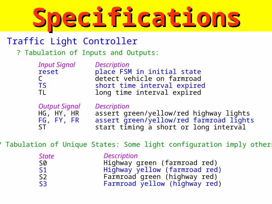
Traffic Light Controller? Tabulation of Inputs and Outputs:
Input SignalresetCTSTL
Output SignalHG, HY, HRFG, FY, FRST
Descriptionplace FSM in initial statedetect vehicle on farmroadshort time interval expiredlong time interval expired
Descriptionassert green/yellow/red highway lightsassert green/yellow/red farmroad lightsstart timing a short or long interval
? Tabulation of Unique States: Some light configuration imply others
StateS0S1S2S3
DescriptionHighway green (farmroad red)Highway yellow (farmroad red)Farmroad green (highway red)Farmroad yellow (highway red)
SpecificationsSpecifications

The block diagramThe block diagram
TL
FF’sComb.circuits
Comb.circuits
staten_stateC
TS
HRHGHYFRFGFY

State transition diagramState transition diagram
S0: HG
S1: HY
S2: FG
S3: FY
Reset
TL + C
S0TL•C/ST
TS
S1 S3
S2
TS/ST
TS/ST
TL + C/ST
TS
TL • C

Verilog DescriptionVerilog Descriptionmodule traffic_light(HG, HY, HR, FG, FY, FR,ST_o,
tl, ts, clk, reset, c) ;output HG, HY, HR, FG, FY, FR, ST_o;input tl, ts, clk, reset, c ;reg ST_o, ST ;reg[0:1] state, next_state ;parameter EVEN= 0, ODD=1 ;parameter S0= 2'b00, S1=2'b01, S2=2'b10, S3=2'b11;assign HG = (state == S0) ;assign HY = (state == S1) ;assign HR = ((state == S2)||(state == S3)) ;assign FG = (state == S2) ;assign FY = (state == S3) ;assign FR = ((state == S0)||(state == S1)) ;
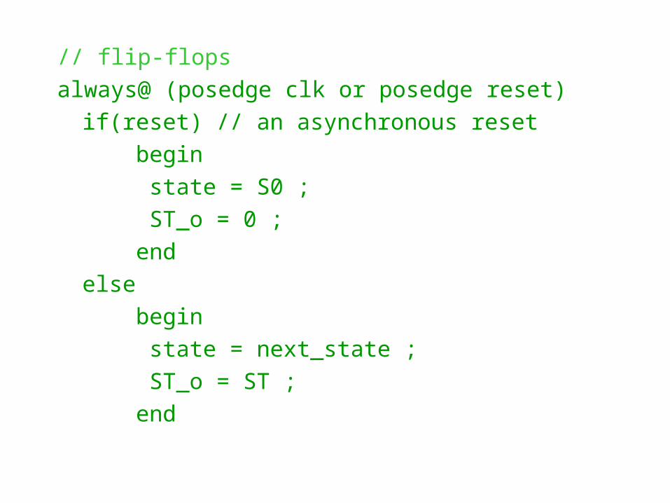
// flip-flops
always@ (posedge clk or posedge reset)
if(reset) // an asynchronous reset
begin
state = S0 ;
ST_o = 0 ;
end
else
begin
state = next_state ;
ST_o = ST ;
end

always@ (state or c or tl or ts)
case(state) // state transition
S0:
if(tl & c)
begin
next_state = S1 ;
ST = 1 ;
end
else
begin
next_state = S0 ;
ST = 0 ;
end
Reset
TL + C
S0TL•C/ST
TS
S1 S3
S2
TS/ST
TS/ST
TL + C/ST
TS
TL • C

S1:if (ts) begin
next_state = S2 ;ST = 1 ;
endelse begin
next_state = S1 ;ST = 0 ;
end S2:
if(tl | !c) beginnext_state = S3 ;ST = 1 ;
endelse begin
next_state = S2 ;ST = 0 ;
end
Reset
TL + C
S0TL•C/ST
TS
S1 S3
S2
TS/ST
TS/ST
TL + C/ST
TS
TL • C

S3:
if(ts)
begin
next_state = S0 ;
ST = 1 ;
end
else
begin
next_state = S3 ;
ST = 0 ;
end
endcase
endmodule
Reset
TL + C
S0TL•C/ST
TS
S1 S3
S2
TS/ST
TS/ST
TL + C/ST
TS
TL • C

Efficient Modeling Efficient Modeling TechniquesTechniques
• Separate combinational and sequential circuits– always know your target circuits
• Separate structured circuits and random logic– structured: data path, XORs, MUXs
– random logic: control logic, decoder, encoder
• Use parentheses control complex structure
• .....

VVERILOG Coding StylesERILOG Coding Styles
Synthesizable
Behavioral
Register Transfer Level (RTL)
Structural

Behavioral Behavioral modelingmodeling

Conditional Instructions Conditional Instructions
if (<condition>)<statement1>
else<statement2>
case (<expression>)expr1: <statement1>;expr2: <statement2>;default: <statement3>;
endcase;
casez (Z considered don’t care)
casex (Z and X considered don’t care)
(expression)?(true):(false)
if (a[2:0]==3’b010 && cy)...
case (ir[7:4])4’b0001: ...4’b0010: ...default: ...
endcase;
casex (ir[7:4])4’bxx01: ...4’bxx10: ...default: ...
endcase;
acc=(ir[7:0]==4’b0011) ? 0:255;

LoopsLoops
for (<start>;<end_exp>;<update>)<statement>;
while (<condition>)<statement>;
repeat (<loop_count>)<statement>;
forever <statement>;
for (i=0;i<8;i=i+1)...
while (i<8)...
repeat (10)begin
a[i]=a[i+1];i=i+1;
end;
forevera = b;

SubroutinesSubroutines
task multiplyinput [15:0] a, b;output [31:0] prod;
begin...end
endtask
function [1:0] testDF;input [1:0] Duab, Dvab;
begin...testDF=2’b01;end
endfunction

Modeling BehaviorModeling Behavior• Behavioral Modeling
Describes functionality of a module
• Module BehaviorCollection of concurrent processes
1. Continuous assignments
2. Initial blocks
3. Always blocks

Behavior: Verilog OperatorsBehavior: Verilog Operators
Arithmetic: +, = , *, /, %
Binary bitwise: ~, &, |, ^, ~^
Unary reduction: &, ~&, |, ~|, ^, ~^
Logical: !, &&, ||, ==, ===, !=, !==
== returns x if any of the input bits is x or z
=== compares xs and zs
Relational: <. >, <=, >+
Logical shift: >>, <<
Conditional: ?:
Concatenation: {}

Behavior:Continuous AssignmentBehavior:Continuous Assignment
Continually drive wire variables
Used to model combinational logic or make connections between wires
Module half_adder(x, y, s, c)input x, y;output s, c;
assign s = x ^ y;assign c = x & y;
endmodule
Module adder_4(a, b, ci, s, co)input [3:0] a, b;input ci;output [3:0]s;output co;
assign {co, s} = a + b + ci;
endmodule

Behavior: Initial and AlwaysBehavior: Initial and Always• Multiple statements per block
Procedural assignmentsTiming control
• Initial blocks execute once• at t = 0
• Always blocks execute continuously• at t = 0 and repeatedly thereafter
initialbegin
• • •
end
alwaysbegin
• • •
end

Behavior: Procedural assignmentsBehavior: Procedural assignments• Blocking assignment =
Regular assignment inside procedural block
Assignment takes place immediately
LHS must be a register
• Nonblocking assignment <=Compute RHS
Assignment takes place at end of block
LHS must be a register
alwaysbegin
A = B;B = A;
end
alwaysbegin
A <= B;B <= A;
end
swap A and B
A = B, B= B
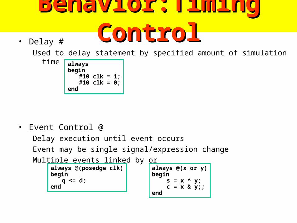
Behavior:Timing ControlBehavior:Timing Control• Delay #
Used to delay statement by specified amount of simulation time
• Event Control @Delay execution until event occurs
Event may be single signal/expression change
Multiple events linked by or
alwaysbegin
#10 clk = 1;#10 clk = 0;
end
always @(posedge clk)begin
q <= d;end
always @(x or y)begin
s = x ^ y; c = x & y;;
end
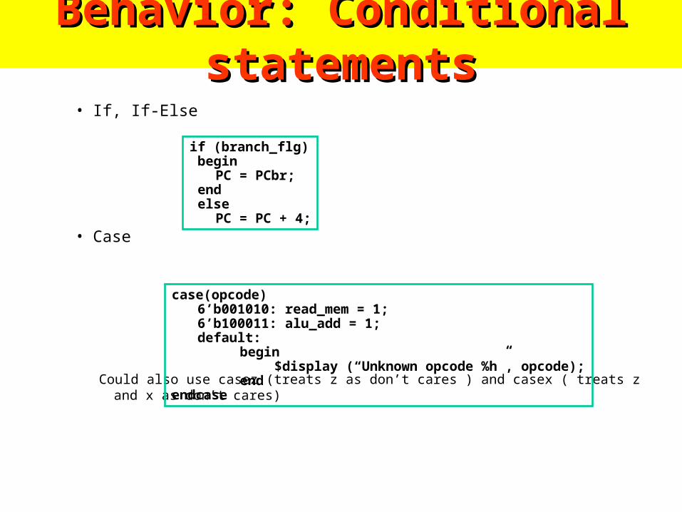
Behavior: Conditional statementsBehavior: Conditional statements
• If, If-Else
• Case
Could also use casez (treats z as don’t cares ) and casex ( treats z and x as don’t cares)
if (branch_flg) begin
PC = PCbr; end else
PC = PC + 4;
case(opcode)6’b001010: read_mem = 1;6’b100011: alu_add = 1;default:
begin$display (“Unknown opcode %h”, opcode);
endendcase

Behavior: Loop StatementsBehavior: Loop Statements• Repeat
• While
• For
i = 0;repeat (10) begin
i = i + 1;$display( “i = %d”, i);
end
i = 0;while (i < 10) begin
i = i + 1;$display( “i = %d”, i);
end
for (i = 0; i < 10; i = i + 1) begin
i = i + 1;$display( “i = %d”, i);
end

Verilog Coding RulesVerilog Coding Rules• Coding rules eliminate strange simulation behavior
– When modeling sequential logic, use nonblocking assignments
– When modeling combinational logic with always block, use blocking assignments. Make sure all RHS variables in block appear in @ expression
– If you mix sequential and combinational logic within the same always block use nonblocking assignments
– Don’t mix blocking and nonblocking assignments in the same always block
– Don’t make assignments to same variable from more than one always block
– Don’t make assignments using #0 delays
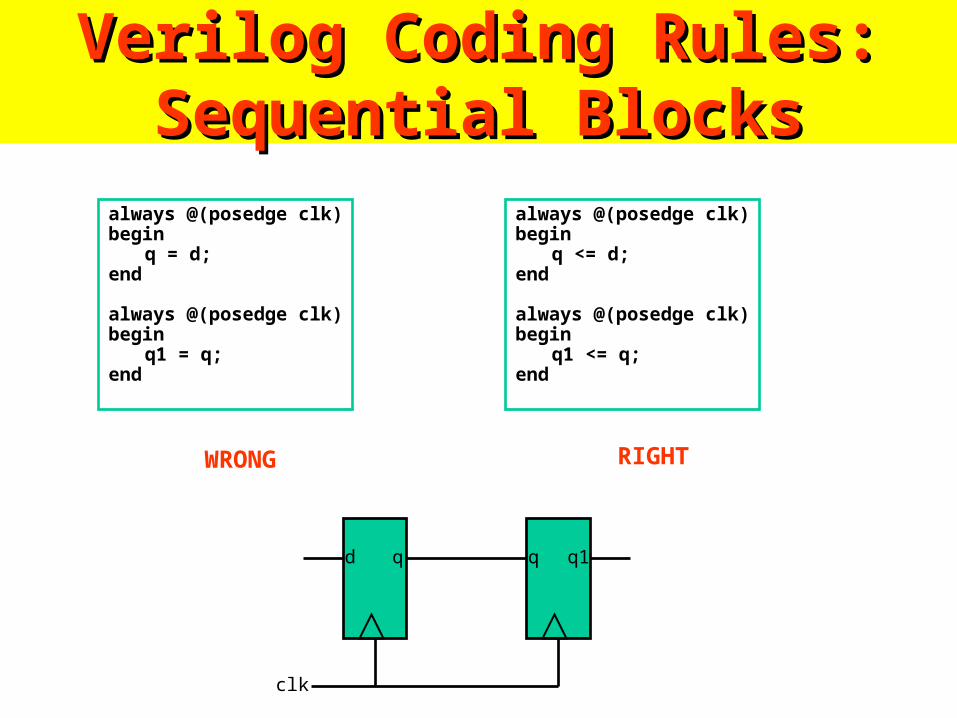
Verilog Coding Rules: Sequential Verilog Coding Rules: Sequential BlocksBlocks
always @(posedge clk)begin
q = d;end
always @(posedge clk)begin
q1 = q;end
always @(posedge clk)begin
q <= d;end
always @(posedge clk)begin
q1 <= q;end
qd q1q
clk
WRONG RIGHT

183 Verilog Synthesizable 183 Verilog Synthesizable coding rulescoding rules
- Always keep in mind what sort of implementation your design could map to. If you don’t know, chances are synthesis doesn’t either.
- The only allowed storage is instantiated dff- No always @ posedge statements
- No case statements without default case
- No if statements without an else case
- If you assign to a net in one case it must be assigned to in all cases (no implicit storage)
- No loops
- No initial blocks
- Limited operators- + and – are the only arithmetic operators allowed
- Try to avoid relational operators (>, ==) in favor of simpler logic
- Use assign statements when possible

System and CompilerSystem and Compiler• System tasks
– $time - returns the current simulation time– $display - similar to printf in C– $stop - stops simultion– $finish - ends simulation– $readmemh - load memory array from text file in hex format
– Many more …
• Compiler directives– A compiler directive is preceded by `– `define - defines a compiler time constant or macro– `ifdef, `else, `endif - conditional compilation– `include - text inclusion

Verilog Verilog Example: ASM Example: ASM
ChartChart
idle
input0
s1
input
s2
input
s3
input
1
0 1
10
1 0
s3
output
input1 0
Want to match pattern1011

Verilog Example (cont)Verilog Example (cont)module sequence (dataIn, found, clock, reset);
//Input and Output Declarations input dataIn; input clock; input reset; output found; reg found;
//DataInternal Variables reg [3:0] state; reg [3:0] next_state; wire found_comb;
//State Declarations parameter idle = 4'b0001; parameter s1 = 4'b0010; parameter s2 = 4'b0100; parameter s3 = 4'b1000;

Verilog Verilog ExampleExample
//Next State Logicalways @(state or dataIn) case (state) idle: if (dataIn)
next_state = s1; else
next_state = idle; s1: if (dataIn)
next_state = s1; else
next_state = s2; s2: if (dataIn)
next_state = s3; else
next_state = idle; s3: if (dataIn)
next_state = s1; else
next_state = s2; default: next_state = idle; endcase // case(state)

Verilog Verilog ExampleExample
//State Transitionalways @(posedge clock) if (reset == 1) state <= idle; else state <= next_state;
//Output Logicassign found_comb = (state[3] & dataIn);
//Register Output Logicalways @(posedge clock) if (reset == 1) found <= 0; else found <= found_comb;
endmodule // sequence

Verilog Example : Verilog Example : SimulationSimulation

Verilog Example: SynthesisVerilog Example: Synthesis• Top Level
• Technology view (Altera 10K)
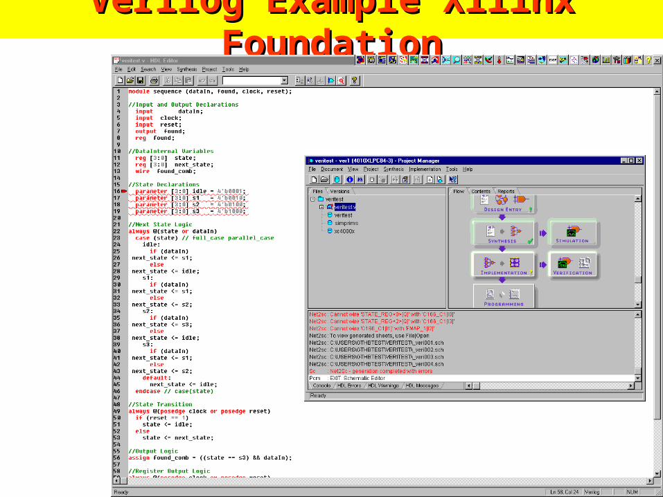
Verilog Example Xilinx FoundationVerilog Example Xilinx Foundation

Verilog Example Xilinx FoundationVerilog Example Xilinx Foundation

Binary Multiplier ExampleBinary Multiplier Example
Register B
Shift register A Shift register QC
Adder
Cout
IN
0
OUT
product
multiplicand
multiplier
Counter P
n-1

Behavioral modelingBehavioral modelingLearning behavioral modeling by exploring some examples
DFF
Din
Clock
Dout
Reset
module DFF ( Din, Dout, Clock, Reset );
output Dout;
input Din, Clock, Reset;
reg Dout;
always @( negedge Reset or posedge Clock )
begin
if ( !Reset )
Dout <= 1’b0;
else
Dout <= Din;
end
endmodule

Behavioral modeling ( cont. )Behavioral modeling ( cont. )
outMUX
sel
4
4
i0
i1
i2
i3
2module MUX4_1 ( out, i0, i1, i2, i3, sel );
output [3:0] out;
input [3:0] i0, i1, i2, i3;
input [1:0] sel;
assign out = ( sel == 2’b00 ) ? i0 :
( sel == 2’b01 ) ? i1 :
( sel == 2’b10 ) ? i2 :
( sel == 2’b11 ) ? i3 :
4’bx;
endmodule

Behavioral modeling ( cont. )Behavioral modeling ( cont. )
`define pass_accum 4’b0000
`define pass_data 4’b0001
`define ADD 4’b0010
……
always@ ( opcode ) begin
case ( opcode )
`pass_accum : alu_out <= accum;
`pass_data : alu_out <= data;
`ADD : alu_out <= accum + data;
`AND : alu_out <= accum ^ data;
default : alu_out <= 8’bx;
endcase
end

Module InstantiationModule Instantiation
out0
out1
AB
Top
i0
i1out
Data0
a1
a0 b0
b1
Data1
Data2
A_to_B
module Top ( Data0, Data1, Data2,
out0, out1 );
input Data0, Data1, Data2;
output out0, out1;
wire A_to_B;
A a1 ( .i0( Data0 ), .i1( Data1 ),
.out( A_to_B ) );
B b1 ( .a0( A_to_B ), .a1( Data2 ),
.b0( out0 ), .b1( out1 ) );
endmodule
Port mapping

• Verilog:wire Valid = VL1 & !Illegal;
wire Valid2Sched = !SchedFreeze_ & (Valid_D | Valid);
wire [16:0] LinkIdOMaskL1 = 1'b1 << LinkIdL1;
• netlist:not(n1, Illegal)
and(n2, n1, VL1)
...

SynthesizableSynthesizable Verilog #3Verilog #3 FSMsFSMsparameter IDLE=0, SET_HOURS=1, SET_MINUTES=2;reg [1:0] CURRENT_STATE, NEXT_STATE; // State reg HOURS, MINS; // Outputs
always @ (CURRENT_STATE or ALARM_BUTTON or HOURS_BUTTON or MINUTES_BUTTON) // ADD Clock for synchronous FSM
begin
HOURS = 0; MINS = 0; NEXT_STATE = CURRENT_STATE;
case (CURRENT_STATE) //synopsys full_case parallel_case IDLE: begin if (ALARM_BUTTON & HOURS_BUTTON & !MINUTES_BUTTON) begin
NEXT_STATE = SET_HOURS; HOURS = 1; end
else if (ALARM_BUTTON & !HOURS_BUTTON & MINUTES_BUTTON)
...

modulesmodules
module RegLd(Q, D, load, clk);
parameter N = 8;input [N-1:0] Q;output [N-1:0] D;input load, Clk;
always @(posedge clk) if (load) Q = #`dh D;
endmodule
module RegLd(Q, D, load, clk);
parameter N = 8;input [N-1:0] Q;output [N-1:0] D;input load, Clk;
always @(posedge clk) if (load) Q = #`dh D;
endmodule
RegLd reg0(q0, d0, l, clk);
RegLd #16 reg1(q1, d1, l, clk);
RegLd reg2(q2, d2, l, clk);defparam reg2.N = 4;
RegLd reg0(q0, d0, l, clk);
RegLd #16 reg1(q1, d1, l, clk);
RegLd reg2(q2, d2, l, clk);defparam reg2.N = 4;

Sensitivity listsSensitivity lists
always @(posedge clk or negedge rst_) ...
always @(a or b or c) if (opcode == 32’h52A0234E) a = b ^ (~c);
always @(posedge a or posedge b) ...
always @(posedge clk or negedge rst_) ...
always @(a or b or c) if (opcode == 32’h52A0234E) a = b ^ (~c);
always @(posedge a or posedge b) ... !

Behavioral (1)Behavioral (1)
• simulation–
• Test benches–
initial begin // reset everythingend
always @(posedge clk) begin case (opcode) 8’hAB: RegFile[dst] = #2 in; 8’hEF: dst = #2 in0 + in1; 8’h02: Memory[addr] = #2 data; endcase if (branch) dst = #2 br_addr;end
initial begin // reset everythingend
always @(posedge clk) begin case (opcode) 8’hAB: RegFile[dst] = #2 in; 8’hEF: dst = #2 in0 + in1; 8’h02: Memory[addr] = #2 data; endcase if (branch) dst = #2 br_addr;end

Behavioral (2)Behavioral (2)
integer sum, i;integer opcodes [31:0];real average;
initial for (i=0; i<32; i=i+1) opcodes[i] = 0;
always @(posedge clk) begin sum = sum + 1; average = average + (c / sum); opcodes[d] = sum; $display(“sum: %d, avg: %f”, sum, average);end
integer sum, i;integer opcodes [31:0];real average;
initial for (i=0; i<32; i=i+1) opcodes[i] = 0;
always @(posedge clk) begin sum = sum + 1; average = average + (c / sum); opcodes[d] = sum; $display(“sum: %d, avg: %f”, sum, average);end
!

Verification of DesignVerification of Design

Differences Differences between Tasks between Tasks and Functionsand Functions

Tasks versus Functions in Tasks versus Functions in VerilogVerilog
• Procedures/Subroutines/Functions in SW programming languages– The same functionality, in different places
• Verilog equivalence:– Tasks and Functions– Used in behavioral modeling– Part of design hierarchy Hierarchical name

Differences between...Differences between...
• Functions– Can enable (call) just
another function (not task)
– Execute in 0 simulation time
– No timing control statements allowed
– At lease one input
– Return only a single value
• Tasks– Can enable other tasks and
functions
– May execute in non-zero simulation time
– May contain any timing control statements
– May have arbitrary input, output, or inouts
– Do not return any value

Differences between… (cont’d)Differences between… (cont’d)
• Both– are defined in a module
– are local to the module
– can have local variables (registers, but not nets) and events
– contain only behavioral statements
– do not contain initial or always statements
– are called from initial or always statements or other tasks or functions

Differences between… (cont’d)Differences between… (cont’d)
• Tasks can be used for common Verilog code• Function are used when the common code
– is purely combinational
– executes in 0 simulation time
– provides exactly one output
• Functions are typically used for conversions and commonly used calculations

Tasks Tasks

TasksTasks
• Keywords: task, endtask
• Must be used if the procedure has– any timing control constructs– zero or more than one output arguments– no input arguments

Tasks (cont’d)Tasks (cont’d)
• Task declaration and invocation– Declaration syntax
task <task_name>;
<I/O declarations>
<variable and event declarations>begin // if more than one statement needed
<statement(s)>end // if begin used!
endtask

Tasks (cont’d)Tasks (cont’d)
• Task declaration and invocation– Task invocation syntax
<task_name>;
<task_name> (<arguments>);
– input and inout arguments are passed into the task– output and inout arguments are passed back to the
invoking statement when task is completed

Tasks (cont’d)Tasks (cont’d)
• I/O declaration in modules vs. tasks– Both used keywords: input, output, inout– In modules, represent ports
• connect to external signals
– In tasks, represent arguments• pass values to and from the task

Task ExamplesTask Examples Use of input and output arguments Use of input and output arguments
module operation;parameter delay = 10;reg [15:0] A, B;reg [15:0] AB_AND, AB_OR, AB_XOR;
initial$monitor( …);
initialbegin
…end
always @(A or B)begin
bitwise_oper(AB_AND, AB_OR, AB_XOR, A, B);
end
task bitwise_oper;output [15:0] ab_and, ab_or,
ab_xor; input [15:0] a, b; begin #delay ab_and = a & b; ab_or = a | b; ab_xor = a ^ b;endendtask
endmodule

Task ExamplesTask Examples Use of module local variables Use of module local variables
module sequence;
reg clock;
initial
begin
…
end
initial
init_sequence;
always
asymmetric_sequence;
task init_sequence;
begin
clock = 1'b0;
end
endtask
task asymmetric_sequence;
begin
#12 clock = 1'b0;
#5 clock = 1'b1;
#3 clock = 1'b0;
#10 clock = 1'b1;
end
endtask
endmodule

FunctionsFunctions

FunctionsFunctions
• Keyword: function, endfunction
• Can be used if the procedure– does not have any timing control constructs
– returns exactly a single value
– has at least one input argument
Functions (cont’d)Functions (cont’d)
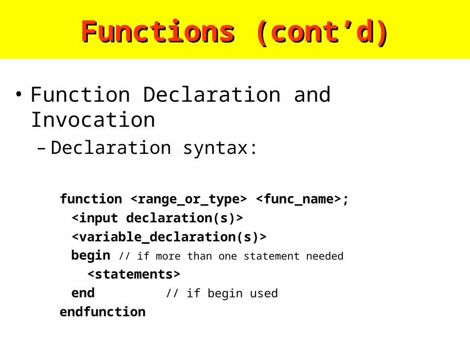
• Function Declaration and Invocation– Declaration syntax:
function <range_or_type> <func_name>;
<input declaration(s)>
<variable_declaration(s)>begin // if more than one statement needed
<statements>
end // if begin used
endfunction

Functions (cont’d)Functions (cont’d)
• Function Declaration and Invocation– Invocation syntax:
<func_name> (<argument(s)>);

Functions (cont’d)Functions (cont’d)
• Semantics – much like function in Pascal– An internal implicit reg is declared inside the function
with the same name– The return value is specified by setting that implicit reg– <range_or_type> defines width and type of the implicit
reg• type can be integer or real
• default bit width is 1
Function ExamplesFunction ExamplesParity GeneratorParity Generator
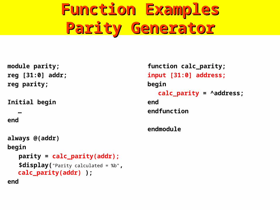
module parity;
reg [31:0] addr;
reg parity;
Initial begin
…
end
always @(addr)
begin
parity = calc_parity(addr);
$display("Parity calculated = %b", calc_parity(addr) );
end
function calc_parity;
input [31:0] address;
begin
calc_parity = ^address;
end
endfunction
endmodule

Function ExamplesFunction ExamplesControllable ShifterControllable Shifter
module shifter;
`define LEFT_SHIFT 1'b0
`define RIGHT_SHIFT 1'b1
reg [31:0] addr, left_addr, right_addr;
reg control;
initial
begin
…
end
always @(addr)begin
left_addr =shift(addr, `LEFT_SHIFT);
right_addr =shift(addr,`RIGHT_SHIFT);
end
function [31:0] shift;
input [31:0] address;
input control;
begin
shift = (control==`LEFT_SHIFT) ?(address<<1) : (address>>1);
end
endfunction
endmodule
Tasks and Functions SummaryTasks and Functions Summary
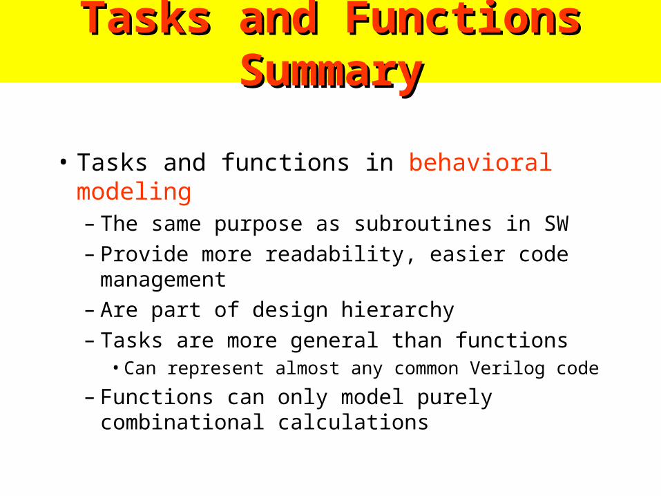
• Tasks and functions in behavioral modeling– The same purpose as subroutines in SW– Provide more readability, easier code management– Are part of design hierarchy– Tasks are more general than functions
• Can represent almost any common Verilog code
– Functions can only model purely combinational calculations

Chap 5. Chap 5.
Arithmetic Functions and Arithmetic Functions and
Circuits Circuits
Spring 2004
Jong Won [email protected]

5-1 Iterative Combinational Circuits5-1 Iterative Combinational Circuits
Figure 5-1 Block Diagram of an Iterative Circuit

5-2 Binary Adders5-2 Binary Adders
• Arithmetic Circuit– a combinational circuit for arithmetic operations
such as addition, subtraction, multiplication, and division
with binary numbers or decimal numbers in a binary code
• Addition of 2 binary inputs, 'Half Adder‘– 0+0=0, 0+1=1, 1+0=1, 1+1 = 10Table 5-1
Truth Table of Half Adder
S = X'Y + XY' = X Å Y; C = XY
Figure 5-2 Logic Diagram of Half Adder

5-2 Binary Adders5-2 Binary Adders
• Addition of 3 binary inputs, 'Full Adder'
Table 5-2Truth Table of Full Adder
Figure 5-3 Logic Diagram of Half Adder
Figure 5-4 Logic Diagram of Full Adder

5-2 Binary Adders5-2 Binary Adders
• Binary Ripple Carry Adder– sum of two n-bit binary numbers in parallel– 4-bit parallel adder
A = 1011, B = 0011
Figure 5-5 4-Bit Ripple Carry Adder
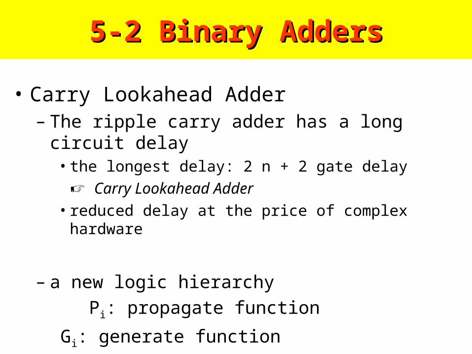
• Carry Lookahead Adder– The ripple carry adder has a long circuit delay
• the longest delay: 2 n + 2 gate delay
Carry Lookahead Adder
• reduced delay at the price of complex hardware
– a new logic hierarchy
Pi: propagate function
Gi: generate function
5-2 Binary Adders5-2 Binary Adders
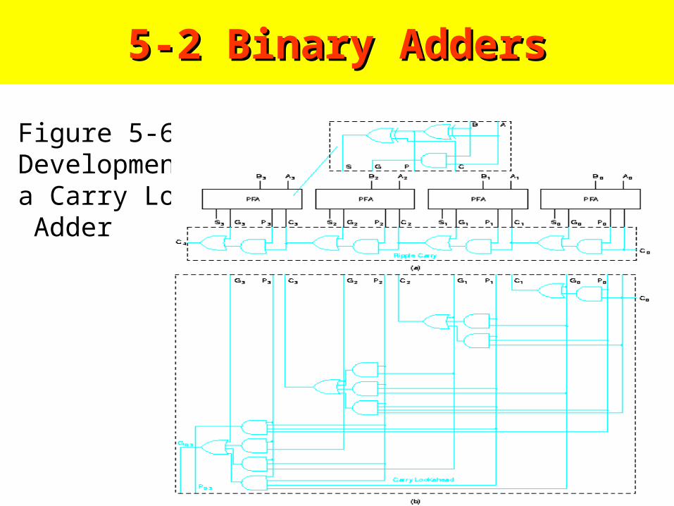
5-2 Binary Adders5-2 Binary Adders
Figure 5-6 Development of a Carry Lookahead Adder

5-3 Binary Subtraction
– Subtraction
– a borrow occurs into the most significant positionM - N ==> M - N + 2n
==> 2n - (M - N + 2n) = N - M
– 1) Subtract the subtrahend N from the minuend M2) If no end borrow occurs, then M > N3) If an end borrow occurs,
then N-M is subtracted from 2n
& minus sign is appended to the result
– Subtraction of a binary number from 2n
"2's complement form"
10 end borrow 63-72-------- 91 100-91 -9

5-3 Binary Subtraction
Ex 5-1) 01100100 - 10010110
Figure 5-7 Block Diagram of Binary Adder-Subtracter

5-3 Binary Subtraction
• Complements– 2 types:
• radix complement: r's complement
• diminished radix complement: (r-1)'s complement– 2's & 1's for binary numbers
– 10's & 9's for decimal numbers
– 1's complement of N (binary number): (2n - 1) - N• 1's comp of 1011001 ==> 0100110
• 1's comp of 0001111 ==> 1110000

5-3 Binary Subtraction
– 2's complement of N: 2n - N for N != 0, 0 for N = 01) add 1 to the 1's complement
• 2's comp of 101100 ==> 010011 + 1 ==> 010100
2) leaving all least significant 0's and the first 1 unchanged then replacing 1's with 0's, 0's with 1's
• 2's comp of 1101100 ==> 0010100
• 2's complement of N is 2n – N & the complement of the complement is 2n -
(2n-N) = N

5-3 Binary Subtraction• Subtraction with
Complements– (M - N)
1) add 2's comp of the subtrahend N to the minuend M
M + (2n-N) = M - N + 2n
2) if M > N, the end cary is discarded3) if M < N, the result is 2n - (N - M) take the 2's complement of the sum & place a minus sign
– avoid overflow problem to accommodate the sum
Ex 5-2) X=1010100 Y=1000011

5-4 Binary Adder-Subtractors
Figure 5-8 Adder-Subtractor Circuit
A - B = A + (-B) in 2's complement form
with exclusive-OR gate (B0=B; B1=B') adder if S = 0; subtractor if S = 1

5-4 Binary Adder-Subtractors
• Signed Binary Numbers– sign bit: 0 for positive numbers
1 for negative numbers
– -9 (=-1001) using 8 bits
1) signed-magnitude representation: 10001001
2) signed 1's complement representation: 1111 0110
3) signed 2's complement representation: 1111 0111
– positive numbers are identical(Table 5-3)
signed-magnitude -7 ~ -1, -0, 0, 1 ~ 7 (2 zeros)
signed 1's comp -7 ~ -1, -0, 0, 1 ~ 7 (2 zeros)
signed 2's comp -8 ~ -1, 0, 1 ~ 7
– signed 1's comp : useful as a logical operation
signed 2's comp : popular in use

5-4 Binary Adder-Subtractors
Table 5-3Signed Binary Numbers

5-4 Binary Adder-Subtractors
– Signed Binary Addition and Subtraction
Ex 5-5) Signed Binary Subtraction Using 2’s Complement
Ex 5-4) Signed Binary Adding Using 2’s Complement
5-4 Binary Adder-Subtractors
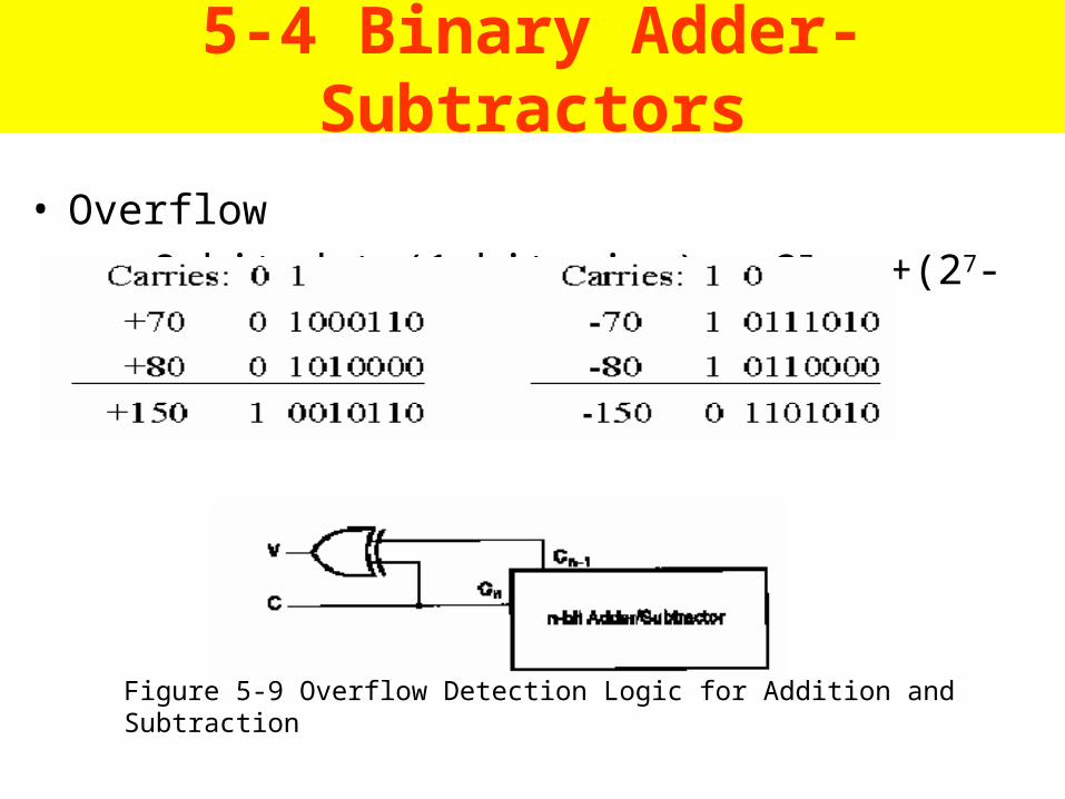
• Overflow
8-bit data(1-bit sign): -27 ~ +(27-1) = -128 ~ +127
Figure 5-9 Overflow Detection Logic for Addition and Subtraction

5-5 Binary Multipliers5-5 Binary Multipliers
• a 2-Bit by 2-Bit Binary Multiplier
Figure 5-10 A 2-Bit by 2-Bit Binary Multiplier

5-5 Binary Multipliers5-5 Binary Multipliers
• a 4-Bit by 3-Bit Binary Multiplier
Figure 5-11 A 4-Bit by 3-Bit Binary Multiplier

5-6 Other Arithmetic Functions5-6 Other Arithmetic FunctionsContraction
making a simpler circuit for a specific application
• Ex 5-6) Contraction of Full Adder Equations

5-6 Other Arithmetic Functions5-6 Other Arithmetic Functions• Ex 5-6) Contraction of Full Adder Equations
• S = A + B + C0 S = A + 11…1 + C0
= A - 1 + C0 (in 2’s complement)
if C0 = 0, S is a decrement of A
Incrementing
adding a fixed value(ex, 1) to an arithmetic variable
N-bit incrementer
S = A + 1 from S = A + B + C0 by setting B to 00..01 and
C0 to 0

5-6 Other Arithmetic Functions5-6 Other Arithmetic Functions
• Incrementing( 중간 0 위치 내림 , X because of 3-bit incrementer)
Figure 5-12 Contraction of Adder to Incrementer

5-6 Other Arithmetic Functions5-6 Other Arithmetic Functions
• Multiplication by Constants
Figure 5-13 Contractions of Multiplier(a) For 101 X B (b) For 100 X B, and(c) For B / 100

5-7 HDL Representations-VHDL5-7 HDL Representations-VHDL• Ex 5-7)Hierarchical
VHDL for
a 4 – Bit Ripple Carry Adder
• V C(3) XOR C4
Figure 5-14 Hierarchical Structure/Dataflow DescriptionOf 4-Bit Full Adder

5-7 HDL Representations5-7 HDL Representations
Figure 5-15 Hierarchical Structure/Dataflow DescriptionOf 4-Bit Full Adder(continued)

5-7 HDL Representations5-7 HDL Representations
• Ex 5-8) Behavioral VHDL for a 4 – Bit Ripple Carry Adder
Figure 5-16 Behavioral Description of 4 – bit Full Adder

5-8 HDL Representations-Velilog5-8 HDL Representations-Velilog
Figure 5-17 Hierarchical Dataflow/Structure Description of 4 – bit Full Adder

5-8 HDL Representations-Velilog5-8 HDL Representations-Velilog
Figure 5-18 Behavioral Description of 4 – bit Full Adder Using Verilog
Ex 5-10) Behavioral VHDL for a 4 – Bit Ripple Carry Adder