introduction of 3d technology & machine control systems
TRANSCRIPT

Introduction of 3D Technology & Machine Control Systems
Bret Alsobrooks

Introduction
De-mystify 3D Machine Control Highlight areas where 3D Machine Control is used and how these projects benefitedHow to analyze which tool will help you meet or exceed project specifications A look at some new, high tech grade control tools that are changing the way grading is being done.

Jones Bros., Inc. GPS Project List
PROJECT D.O.T. COUNTY CITY INTERSTATE 840 Tennessee Williamson Franklin 7 mile 4-lane rock subgrade / I-65 Interchange HIGHWAY 452 Tennessee Wilson Lebanon 6 mile subgrade / I-840 Interchange HIGHWAY 153 Tennessee Hamilton Chattanooga A. 4-Lane, 5 mile 1. Lack of radio signal 2. Poor plans elevation 3. Poor JBI training JOE B. JACKSON PARKWAY Tennessee Rutherford Murfreesboro 4 mile subgrade / I-24 Interchange EASTGATE BLVD. Tennessee Wilson Lebanon Access road for industrial park PRIMARY 29 Virginia Amherst Amherst A. 14 miles 1. Soil cement subgrade 2. Base cement in rock cuts FM 1187 Texas Fort Worth 4-lane, 7 mile subgrade; lime treated subgrade US 71 / 59 INTERCHANGE Texas Texarkana 6 mile subgrade, select fills INTERSTATE 4 / MEMORIAL BLVD. Florida Lakeland CORRIDOR H (Two Projects) West Virginia Hardy 10 mile; 200 ft cuts and fills; boxed cuts; select fills

Introduction
3D Systems require a set “Process” to be followed3D Machine Control Systems are not “Plug and Play” products
I. Key Points for successful 3D operationsII. Trouble shooting techniques that apply
to all 3D systems

“Stakeless” Grade Control
SiteVision GPS
BladePro 3D-ATS

What is “Stakeless” Grade Control ?How does the ‘process’ work?

START FINISH
3D Begins Data Flow Process

SURVEY
BladePro 3D
SiteVision
TOTAL SOLUTION
ENGINEERING
3DProject
Data
Quality Control

Data Preparation
What is required for the field?Finish grade or sub-grade?
Site – finish gradeRoad – finish grade, top of rock, dirt
Pre-calculated points for field layoutStructuresDrainage structuresEdge of pavement, edge of shoulder
Road data with special coding, toe of slopes, ROW,or template breaks

To create a Digital Terrain Mode

Applications of 3D Machine Control and GPS Survey Systems
BladePro 3D (BP3D)- Total Station BasedI. Finishing SubgradeII. Knockdown and placing of materials in various
zonesIII. Finish GradingIV. Phased ConstructionV. Erosion ControlVI. Bridge StructuresVII. DrainageVIII. Signs, Guardrail

What is BladePro 3D?
A Fine Grading tool operating on a Motor Grader.BP3D uses a Geodimeter Automatic Tracking System (ATS) measuring to a sensor mounted on the Motor Grader blade.One ATS Base runs one Motor Grader. Multiple Motor Graders cannot share one ATS.Accuracy +-.02 foot

Applications of 3D Machine Control Systems
Blade-Pro 3D (BP3D) – Motorgrader
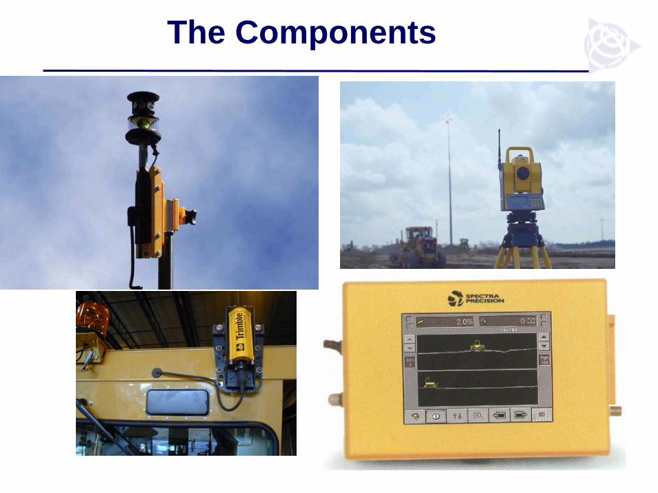
The Components

ATS600
ATS Robotic Total Station Tracks the Position Of The MachineTransfers Position Information Via Radio To Operator Interface

Considerations when using ATS
AdvantagesAccurate results in the range of 0.0’/.02’1000’ to and from instrument for 2000’ total with one instrument set upEasily upgraded to BladePro 3D-GPS, single antenna variant
DisadvantagesMust be line of sight to the machineControls only ONEmachine Gun must be protected from being run overRequires a .PRO file format from TerramodelRange is effected by fog, dust, snow or heavy rain

SiteVision GPS

Real Time Kinemetic GPS
Repeater for difficult terrain

The Global Positioning System (GPS) is used to...
Accurately position the grading machine BLADE , on the 3D digital model of the project
Within 1cm in X and YWithin 1-3 cm in Z = 1.18 of an inchOld school one tenth = 1.2 of an inch
This puts the blade on the design, precisely located in 3D

Four screens available to the operator
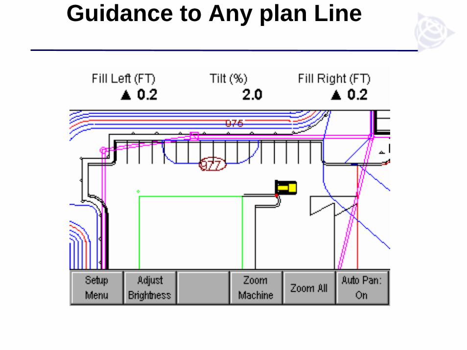
Guidance to Any plan Line

Scaleable Lightbars

Two 13” GPS antennas

Why Two GPS Antennas?

Summary - Two Antennas
Most Accurate Solution!Cuts/Fills calculated along the entire blade cutting edge, from the right tip all the way to the left tip (no matter how the blade is tilted or rotated)Always know which way the machine is facing and moving. (operator must tell the system which direction with single antenna)No need for rotation or tilt sensors that are affected by vibration (especially on dozers)No daily/weekly/monthly calibration of sensors
Gives You:
TWO ANTENNA’S

Dozers D3-D11 manual and automatic

Blades-manual and automatic

Grade checker’s rover

GPS Rover

Considerations when using GPS Technology
AdvantagesPlaces the design in front of the operator.Unlimited machines possible on one baseLine of sight not requiredDramatically increases productionDramatically reduces labor costs-layout,stakesNot effected by fog, dust etc.Operators love to use it!
DisadvantagesYou need a clear view of the sky
Tree canopyTall buildingsBlocking terrain
Requires a local “champion” to manage-
Data and site CalRadio coverageProper application requiring attentionPDOP issues

GPS Technology Gains Construction Phase
Other savings from:Improved utilization of equipment/30%Lower skill level required realize over 100%Erosion control as you go productivity gains
GPS technology Compared with Estimated savingsGrade Checking Manual method Up to 66%Reduction or Elimination of Stakes Using stakes Up to 85%Improved material yields/select fills/undercutting
Overruns using manualmethods
3% to 6% in volume
Un-interrupted earth moving productionunder any weather conditions (24/7)
Daytime / fine weatheroperation only/night work
30% to 50%
RTK, robotics stakeout Traditional survey stakeout
More than 100% in speedand 66% in staffing

Process of 3D Machine Control Systems
Know your contract specifications and tolerances
I. BP3D tolerances are +0.02’ (@ 750’ from the total station) and +0.10’ (@ 1000’ from the total station)
II. GPS tolerances are + 0.10’ (Horizontal and Vertical on the machine)

Process of 3D Machine Control Systems
What is your plus / minus grade and elevation tolerances?
I. How do you meet or exceed these tolerances?
II. Can 3D Machine Control systems compliment this task?
Trained foreman and supporting castIncreased efficiency and cost reduction results from improving the overall process

Process of 3D Machine Control Systems
How to get up and running fasterI. Fully committed to the processII. Draw upon experienced resourcesIII. Stay the course and be willing to follow
through the learning curveIV. Job planningV. Do not panic!
