introduction of the latest technology of energy conservation
TRANSCRIPT
© Fuji Electric Co., Ltd. All rights reserved.
Introduction of the latest Technology of Energy Conservation--- To blue chip companies due to effective energy utilization ---
1
September 15, 2015Fuji Electric Co., Ltd.

© Fuji Electric Co., Ltd. All rights reserved.
Trends and prospects of the world's energy consumption
■Energy consumption trend of expansion■Energy consumption in the world continueto increase in the future, and especiallythe Asian region began to exceed theWestern Europe in the powerconsumption since 1994.Growth rate of the entire world hasremained at an average of approx. 3.5%since 2000, however it has remained at anaverage of 7.5% and a very high growthrate in Asia region.
Long-term power consumption is increased,the anxiety for the power supply to be higher.
adapted from “IEA Energy Balances 2013”.
Changes of energy consumption in the world (by region)
2

© Fuji Electric Co., Ltd. All rights reserved.
Trends in energy prices
Rising the energy price
Enhanced importance of Energy Conservation for companies.Energy prices rise and is also forced to cope with the problem of
global warming.
adapted from “The Institute of Energy Economics, Japan”.
■Energy high price trends■In the medium to long term, energy costsare trend rising with expansion of theenergy demand.In the result, the proportion of energy as apercentage of the product cost to beincreased.Reducing the energy consumption, itbecomes an important factor to competewith other companies.
3

© Fuji Electric Co., Ltd. All rights reserved.
Energy policy of Indonesia (1)
Shift to environment-friendly energy
■Energy shift■Energy configuration of Indonesia shiftsfrom Oil accounted initially 90% to Naturalgas and Coal.Hence, the policy shift to environment-friendly energy.
2006 : National Energy Blueprint2010 : Vision 25/25
4

© Fuji Electric Co., Ltd. All rights reserved.
Energy policy of Indonesia (2)
Energy Conservation - related policies and regulations (1)
Name ContentsLaw No. 30/2007 on Energy •Article 25: Energy Conservation
Government Regulation
No. 70/2009 on EnergyConservation
•Mandatory on EC (Energy Management)•EE Standard and Label•Incentive/Disincentive
PresidentialRegulation/Decree
No. 5/2006 on NationalEnergy Policy
•National RE and EE Target•Energy Elasticity < 1 in 2025
PresidentialInstruction
No. 13/2011 on Energyand Water Saving
•Energy and Water Saving for Government,State-Owned Enterprises
•Target:- Electricity 20%- Fuel 10%- Water 10%
•Periodic reporting
MinisterialRegulation
No. 6/2011 on EE Labelfor Compact FluorescentLight (CFL)
•Implementation of Label for CFL•Mandatory for CFL manufacturer•Self Declaration of Conformity (SDOC)•More star - more efficient
5

© Fuji Electric Co., Ltd. All rights reserved.
Energy policy of Indonesia (3)
Energy Conservation - related policies and regulations (2)
Name ContentsMinisterialRegulation
No. 321 & 323/EN/XII/2011 on Standard of EnergyManager Competence
•Competency of Energy Manager in Industrial andcommercial Building
No. 12/2012 on Fuel Saving •The use non-subsidized fuel•Fuel saving 10%•Gov. Official and State-owned enterprises Vechicle
- 1 June 2012 (Jabodetabek)- 1 August 2012 (Jawa – Bali)
•Vehicles used by plantation and mining companies•Fuel saving for electricy generation•Monitoring
No. 13 /2012 on Electricity Saving
•Electricity saving 20% (Improvement of air system,lighting, & supporting equipment)
•Government/Reg. Gov Office•State-owned enterprises•Street lighting, etc.•Monitoring
No. 14/2012 on Energy Management
•Mandatory of Energy Management for large energyusers (> 6,000 TOE)
•The distribution of Autority (Gov, Reg.Gov.)•Monitoring of Energy Management Implementation•Incentive/Disincentive
6

© Fuji Electric Co., Ltd. All rights reserved.
Considered by classifying the energy
■Considered by classifying the energy■- Efficiency of energy supply- MIERUKA (identifying problems and bringing them to the foreground)- WAKARUKA (to know the weight of numbers, to understand the meaning of the graph)- Energy optimization of production equipment
Energy supply (infrastructure)(Efficiency of energy supply)
Energy consumption (Production process)(Energy optimization)
- Power distribution equipment, etc.
- Production equipment(Manufacturing/ transport equipment, etc.)
- Utility equipment
Energy management (entire factory)(MIERUKA and WAKARUKA of energy)
- Energy management- Equipment management
7

© Fuji Electric Co., Ltd. All rights reserved.
Individual management of energy
■Energy management (MIERUKA)■Centralize energy data, such like electricity and gas, so that it can see from variety ofperspectives utilizing IT technology.With this way, "MIERUKA" is possible in individual units such as "area, equipment andproducts" from entire energy management. Moreover, KAIZEN items for energyconservation can be found.
◆Management by “area, equipment and products”From "Entire management" to "Individual management"
Extra-highvoltage
equipment
High-Lowvoltage
equipment
Eachbuilding
Each distribution panel
…
The electric energy, air and
steam are observed/
managed every day, however
cannot be found how to utilize these data…
Measuringinstrument
WHM
Existingmeasuringinstrument
◆Entire management
Machine panelCT
Measuringinstrument
…CT
Distribution panel
Manufacturing equipment
Fixed/ variable amount is visible by each type when the electricity amount is seen by
specific consumption.It comes see the
questions.
Each floorEach area
Equipment
Measuringinstrument
The specific consumption is getting worse…
The time zone? When what operation? Equipment set
value? What is different last week and/or last time?
8

© Fuji Electric Co., Ltd. All rights reserved.
Electric energy measurement (MIERUKA)
Primary
Secondary
Measurement unit
CT
L1/R L2/S L3/T
9

© Fuji Electric Co., Ltd. All rights reserved.
Case study (WAKARUKA)kWh
16:00
20
40
60
80
90
100
Production
Production results compared to the amount of energy used.
Why is the amount of energy use does not decreasing, even though production has been stopped?
00:0
0
01:0
0
02:0
0
03:0
0
04:0
0
05:0
0
06:0
0
07:0
0
08:0
0
09:0
0
10:0
0
11:0
0
12:0
0
13:0
0
14:0
0
15:0
0
16:0
0
17:0
0
18:0
0
19:0
0
20:0
0
21:0
0
22:0
0
23:0
0
ProductionMachine
Electric furnace
Accessories
!!! FOUND OUT !!!The energy is using by other than production.
10

© Fuji Electric Co., Ltd. All rights reserved.
Target of Energy Conservation
■Sectoral market size, growth rate■
MUSD
adapted from IHS
Target!
11

© Fuji Electric Co., Ltd. All rights reserved.
Motor to be used in HVAC application (fan, pump)
Supply, ventilation and exhaust fanTo transport hot and cold air and exhaust air
Supply, ventilation and exhaust fanTo transport hot and cold air and exhaust air
Hot and cold water pumpTo transport the hot and cold water to the air
conditioner, fan coil.
Hot and cold water pumpTo transport the hot and cold water to the air
conditioner, fan coil.
Cooling water pumpTo transport the heat of the refrigerator to the
cooling tower.
Cooling water pumpTo transport the heat of the refrigerator to the
cooling tower.
Cooling tower fanThe heat dissipation of the cooling water to the
atmosphere.
Cooling tower fanThe heat dissipation of the cooling water to the
atmosphere.
12

© Fuji Electric Co., Ltd. All rights reserved.
General method of adjusting air flow, flow rate
■Damper control■Adjust the air volume in the loss of the damper.
■Valve control■
DamperM
Required air volume
Pump
Valve
Extra pressure according to closing the valve.
Required water flow
M
Adjust the excess capacity of the fan.
Adjust the excess capacity of the flow.
13

© Fuji Electric Co., Ltd. All rights reserved.
What is inverter?
■Inverter■The equipment which can control the motor rotating speed by changing the frequency.
14

© Fuji Electric Co., Ltd. All rights reserved.
Controlled by inverter
■Damper control■The air flow is adjusted by the loss of damper.
■Inverter control (Air flow is adjusted by motor rotating speed)■
DamperM
Commercial drive(50/60Hz)
Inverter control the frequency.(motor speed)
Fully opened damper
No energy loss
15
Adjust the excess capacity of the fan.
Required air volume
Required air volume

© Fuji Electric Co., Ltd. All rights reserved.
Energy Conservation theory
Adjusted valveValve open
50Hz
Required flow
Flow
Pressure
Required energy of valve open.
Required energy of valve adjusting.
Amount of work adjusted by valve (electricity power) Amount of work adjusted by inverter (electricity power)
Adjusted valveValve open
50Hz
Required flow
Flow
Pressure
Adjusted 40Hzby inverter
Required energy of inverter drive.
Required energy of valve adjusting.
16

© Fuji Electric Co., Ltd. All rights reserved.
Energy Conservation by inverter (Operational change)P
ower
con
sum
ptio
n (k
W)
Min. load : 18kW
Max. load : 31.5kWDamper control
month
Dryseason
Rainyseason
Load capacity : 45kW
Inverter control
Power consumption of equipment
36kW
Energy Conservation by damper control
Energy Conservation by inverter control
Design margin 30%
Required max. capacity
Inverter control
17

© Fuji Electric Co., Ltd. All rights reserved.
Energy Conservation target (example) by the inverter (1)
Business : Wood processing, metal processing, etc.Equipment : Bag filter, blower motor for dust collectorPoint : Check if adjusting the air volume in the
damper?
Business : Factory, building, etc.Equipment : Air blower fanPoint : Check if adjusting the air volume in the
damper?
Dust collector of wood processing Foundry dust collector Air handling unit (AHU)
Adjusted by damper
18

© Fuji Electric Co., Ltd. All rights reserved.
Energy Conservation target (example) by the inverter (2)
Business : Chemical plant, etc.Equipment : Cooling tower circulation pumpPoint : Check if adjusting the flow rate in the valve.
Business : Factory, building, etc.Equipment : Cooling water circulation pump of the
refrigerator (chiller)Point : Check if adjusting the flow rate in the valve.
Cooling tower
Circulation pump
Cooling tower
Circulation pump
19
© Fuji Electric Co., Ltd. All rights reserved.
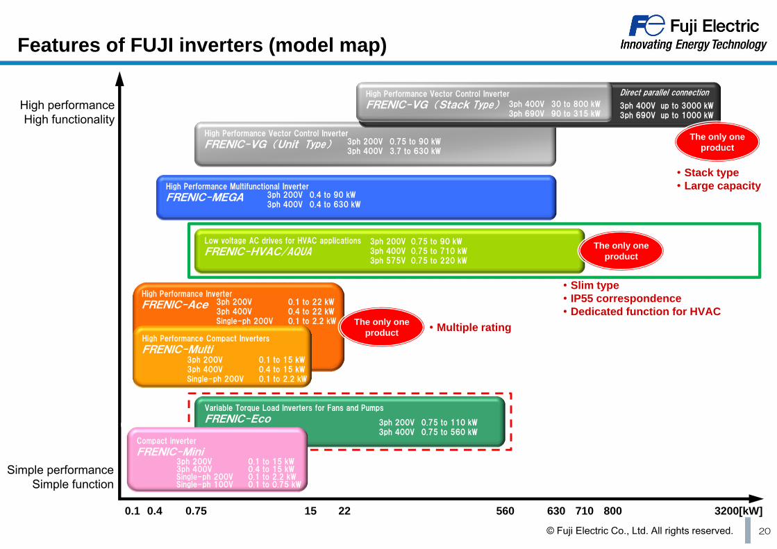
Features of FUJI inverters (model map)
3ph 200V 0.75 to 90 kW3ph 400V 0.75 to 710 kW3ph 575V 0.75 to 220 kW
Low voltage AC drives for HVAC applications
FRENIC-HVAC/AQUA
3ph 200V 0.75 to 90 kW3ph 400V 3.7 to 630 kW
High Performance Vector Control Inverter
FRENIC-VG (Unit Type)
High Performance Inverter
FRENIC-Ace
3ph 200V 0.4 to 90 kW3ph 400V 0.4 to 630 kW
High performanceHigh functionality
Simple performanceSimple function
0.1 0.4 0.75 15 560 630 710
High Performance Multifunctional Inverter
FRENIC-MEGA
3ph 200V 0.1 to 15 kW3ph 400V 0.4 to 15 kWSingle-ph 200V 0.1 to 2.2 kW
High Performance Compact Inverters
FRENIC-Multi
3ph 200V 0.75 to 110 kW3ph 400V 0.75 to 560 kW
Variable Torque Load Inverters for Fans and Pumps
FRENIC-Eco
3ph 200V 0.1 to 22 kW3ph 400V 0.4 to 22 kWSingle-ph 200V 0.1 to 2.2 kW
22 3200[kW]
3ph 400V 30 to 800 kW3ph 690V 90 to 315 kW
High Performance Vector Control Inverter
FRENIC-VG (Stack Type)Direct parallel connection
3ph 400V up to 3000 kW3ph 690V up to 1000 kW
・Multiple ratingThe only one product
The only one product
・Slim type・IP55 correspondence・Dedicated function for HVAC
The only one product
・Stack type・Large capacity
800
3ph 200V 0.1 to 15 kW3ph 400V 0.4 to 15 kWSingle-ph 200V 0.1 to 2.2 kWSingle-ph 100V 0.1 to 0.75 kW
Compact inverter
FRENIC-Mini
20
© Fuji Electric Co., Ltd. All rights reserved.
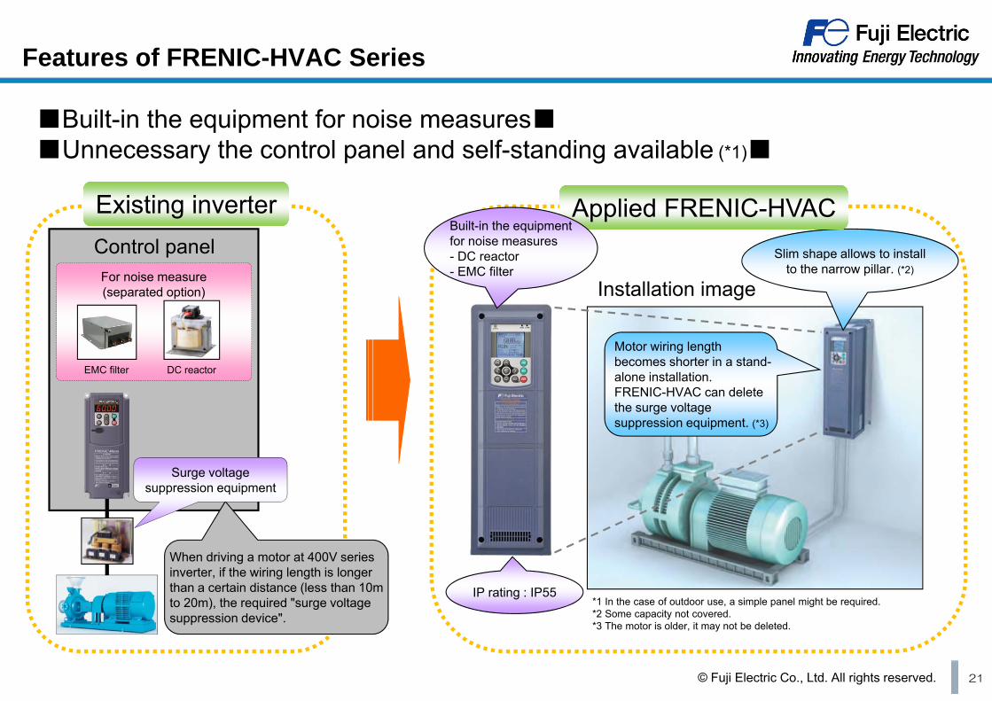
Features of FRENIC-HVAC Series
For noise measure(separated option)
*1 In the case of outdoor use, a simple panel might be required.*2 Some capacity not covered.*3 The motor is older, it may not be deleted.
DC reactorEMC filter
Control panel Slim shape allows to install to the narrow pillar. (*2)
Applied FRENIC-HVACApplied FRENIC-HVACExisting inverterExisting inverter
IP rating : IP55
Motor wiring length becomes shorter in a stand-alone installation.FRENIC-HVAC can delete the surge voltage suppression equipment. (*3)
When driving a motor at 400V series inverter, if the wiring length is longer than a certain distance (less than 10m to 20m), the required "surge voltage suppression device".
Installation image
■Built-in the equipment for noise measures■■Unnecessary the control panel and self-standing available (*1)■
Surge voltagesuppression equipment
Built-in the equipment for noise measures- DC reactor- EMC filter
21

© Fuji Electric Co., Ltd. All rights reserved.
Reduction of peripheral equipment
Existing inverter forfan, pump
controller
Sequence control
Flow rate
Temp.
Pressure
controller
Controller is required.
Inverter for HVAC applicationFRENIC-HVAC
FRENIC-EcoPlus
controller
Sequence control
Flow rate
Temp.
Pressure
controller
Controller is NOT required.
Energy Conservation control software built-in.Sequence control software built-in.
22

© Fuji Electric Co., Ltd. All rights reserved. 23
Challenge to further Energy Conservation
Fixed waste is controlled by the inverter. (traditional control of inverter)
- Waste of adjusting by the valve or damper- Waste of extra flow- Waste of backing in the bypass
Controlled by the inverter to be the optimum value. (future control of inverter)
- Temperature difference constant control- Estimated terminal pressure control - Flow rate (pressure) controlled by two-way valve to be controlled by inverter.- Wet-bulb temperature presumption control

© Fuji Electric Co., Ltd. All rights reserved. 24
What is the optimum value control…
■Further Energy Conservation of existing inverter controlled facilities■
← E
quipment speed
Time →
Equipment speed(before Energy Conservation)
Energy Conservation effect
Speed of the equipment actually required.
Equipment speed(after Energy Conservation)
←E
quipment speed
Time →
Energy Conservation effect
Equipment speed(after optimum value control)
Waste of energy
Reduce the speed of the equipment Control the speed of the equipment
Speed of the equipment actually required.

© Fuji Electric Co., Ltd. All rights reserved. 25
Temperature difference constant control
■Temperature difference constant control for cold water pump■Control the cooling water pump so that the temperature difference between the coolingwater outlet and inlet all times a constant.
Reduce the pump power to less than half.
Cooling tower
F1
Cooling water flow rate F1
Cooling water pump
t1
t1’ Refrigerator
t2’
t2
F2
Primary cooling water flow rate F2
Primary pump
INV INV Minimum flow
rate of the cooling water
In some cases, controls the temperature difference between the inlet and outlet constant in HVAC equipment.If become a temperature difference is constant and does not circulate the coolant more than necessary, can be performed to save energy by lowering the rotational speed of the motor.

© Fuji Electric Co., Ltd. All rights reserved. 26
Estimated terminal pressure control
■Estimated terminal pressure control for cold (hot) water of secondary pump■When the cooling (heating) load is light; less discharge flow rate of the pump, convey the cold (hot) water by lowering the water pressure of the secondary pump as per proper value.
header
Discharge pressure constant control
Estimated terminalpressure control
Convert the flow rate signal to the target pressure in the linearization function.(There is a method for inputting a data value of 3 points, and method of entering a formula.)Lower/ upper limit setting on the linearize output is also possible.
Two-way valve
F
Water pressureP
Load flow rateheader
Terminal pressure
