introduction preflight and post flight pilot services ... · general codes based on “general and...
TRANSCRIPT

ERSA INTRODUCTION
INTRODUCTIONPreflight and Post Flight Pilot Services
Ready Reference GuidePreflight - Civil
NAIPS Internet Service www.airservicesaustralia.com/flight-briefing/
Flight Notification: submission, change and cancellation
1800 805 150^02 6268 5062^
AVFAX 1800 805 150
METBRIEF 1800 805 150
Fax Flight Notification 1800 805 15002 6268 5033
Preflight - Military
Briefing Officer PH 1800 249 030^ or fax 1800 816 089
NOTAM/LJR PH 02 6268 5063^ or fax 02 6268 5044
MET - Defence Meteorological Office (Defence MO) PH 02 6262 7316 or 1800 203 860
Cancellation of SARTIME
Flightwatch (CENSAR) Australia Wide 1800 814 931^
Full Reporting Arrivals
Brisbane FIR (YBBB) 07 3866 3868^
Melbourne FIR (YMMM) 03 9235 2039^
Safety Related Matters
Brisbane ATC Centre 07 3866 3868^
Melbourne ATC Centre 03 9338 4032^
Perth ATC Centre 08 9476 8545^
Sydney ATC Centre 02 9556 6875^
Joint Rescue Coordination Centre (JRCC) Australia
SAR Hotline (within Australia) 1800 815 257
SAR Hotline (outside Australia) +61 2 6230 6899
Australian Transport Safety Bureau
Aviation Accident Notification 1800 011 034
Confidential Aviation Reporting 1800 020 505
Airservices National Helpdesk H24 1800 801 960
Note: Telephone numbers marked with the symbol ^ are recorded facilities.
1. EN ROUTE SUPPLEMENT AUSTRALIA1.1 The En Route Supplement Australia (ERSA) is issued on a 13 week cycle with
amendments issued for MIL users every four weeks in the ADF Aeronautical Information Package Amendment Bulletin (AIPAB).
2. AERODROME AND FACILITY DIRECTORY2.1 This directory within the ERSA, lists alphabetically, details of AD, Navigation Aids, Air Traffic
Services, Ground Services, Public Facilities available and Special Procedures. AD having more than one name are usually identified by the City/AD method.
INTRO - 121 MAY 2020
21 MAY 20

ERSA INTRODUCTION
2.2 The information published within the ERSA is subject to standards and legislative requirements to ensure the quality and integrity of the data and information. More information about Data Product Specifications can be obtained from the Airservices Website: http://www.airservicesaustralia.com/services/aeronautical-information-and-management-services/
3. AIR TRAFFIC SERVICES FREQUENCIES3.1 Air Traffic Control operates these frequencies in various groups and re-transmission applies
within each group.
4. AERODROME INFORMATION4.1 AERODROMES WITH FULL INFORMATION4.2 Aerodromes with full information provided are:
a. Certified aerodromes,b. Registered aerodromes; andc. Military.These entries are subject to inspection and ARE SUBJECT TO NOTAM ACTION.
4.3 AERODROMES WITH LIMITED INFORMATIONa. Other aerodromes, also known as Aircraft Landing Area (ALA) may be included in
ERSA with limited information.b. Under Civil Aviation Safety Regulations, the ALAs are not subject to NOTAM action.
The ALAs are depicted in ERSA with a grey background as shown in INTRO.c. Operators conducting regular public transport or charter operations into ALAs need to
be aware of their obligations under the CASA regulations.Prior to commencing a flight to an uncertified or unregistered aerodrome, a pilot or operator must contact the Aerodrome Operator to ensure currency of aerodrome information.
4.4 A NOTAM service is provided for certified aerodromes, registered aerodromes, certain other aerodromes regulated under CASR Part 139.D and specialised helicopter operations with published terminal instrument flight procedures under CASR Part 173. Limited information is published in ERSA for some aircraft landing areas (ALAs) and a NOTAM service is not provided except: a. For changes to NAVAIDS, CTAF or ATS frequencies when requested by the service
provider or CASA, orb. For changes to special procedures when requested by Airservices Australia or CASA.
4.5 Aerodrome NOTAM will be issued as:a. Location-specific if the location has an AVFAX code; orb. Sub-FIR if the location does not have an AVFAX code.
5. NOTICES5.1 Heights (feet) and short distances (metres) are indicated in NOTICES as follows, e.g.
CAUTION: Fence 10 FT ABV 22M W of RWS end, RWY 26.
6. CIVIL USERS - CHANGE OF ADDRESS AND PROCUREMENTTo advise change of address and to arrange for procurement, visit the CanPrint Communications online AIP shop.a. Internet: www.aipshop.canprint.com.aub. Personal Purchase: the location of reseller outlets in each state and territory can be
obtained from the website identified above.Enquiries OnlyPhone: 1300 306 630+61 2 6293 8381 (international customers only)Email: [email protected] made from mobile phones attract the normal mobile call charge.
INTRO - 221 MAY 2020
21 MAY 20
ERSA INTRODUCTION
7. CIVIL USERS - LICENSING/MEDICAL/EXAMINATION ENQUIRIES7.1 Queries concerning aircrew licensing, medicals or flight crew examinations should be
directed to CASA, Phone 131757.
8. CIVIL USERS - ADVICE OF ERRORS8.1 Due to the volume of correspondence received from civil users it would be impractical to
attempt to deal with the majority of these corrections by telephone. Internet and email addresses have been included below. Users are urged to forward suggestions or notify AIS of errors.
8.2 HEAD OFFICE CONTACT DETAILS (in order of preference)a. [email protected] orwww.airservicesaustralia.com/publications/e-correction-card/b. Mail:Aeronautical Information ServiceCANBERRAGPO BOX 367CANBERRA ACT 2601orBusiness Reply PostPERMIT No. 1986 - CIVIC SQUAREAIRSERVICES AUSTRALIAATTN: AISGPO Box 367,Canberra, ACT2601
8.3 The Australian aviation community has an ongoing need to obtain and maintain accurate information about tall structures so that risks associated with inadvertent collision by low flying aircraft can be reduced. The appropriate reporting form is available at:http://www.casa.gov.au/files/139c08pdf
9. CIVIL AVIATION SAFETY AUTHORITY ADDRESSCivil Aviation Safety AuthorityGPO Box 2005,CANBERRA, ACT, 2601.Phone 131757Web: http://casa.gov.au/
10. ADF USERS - ADVICE OF ERRORS10.1 Advice of Errors10.1.1 ADF users are to notify AIS-AF of errors or omissions as soon as they become apparent,
together with as much detail as possible to allow investigation and validation of the information. The method of notification is dependent on the nature and importance of the incorrect information.
10.1.2 Where the error or omission is urgent or critical to flight safety, the most expeditious means of notification is to be used.
10.1.3 AIS-AF contact details are provided in all ADF FLIP publications.10.2 Routine Changes and/or Recommendations10.2.1 Facility and aircraft operating authorities have obligations, under various orders and
instructions, to review and notify FLIP revisions through appropriate authorities.
INTRO - 321 MAY 2020
21 MAY 20

ERSA INTRODUCTION
AERODROMES AND FACILITIES AND LEGENDSNote 1: All elevations in this document are given in AMSL unless annotated otherwise.Note 2: Telephone numbers marked with the symbol ^ are recorded facilities.CAUTIONOperations at uncertified and unregistered AerodromesThe information about the movement areas and lighting details of aerodromes that are uncertified and unregistered is subject to change without prior notice and is NOT subject to NOTAM action.Pilots and operators must contact the aerodrome operator directly to ensure currency and accuracy of aerodrome information.The following depiction is an example of the background colouring used to annotate an uncertified and unregistered aerodrome.
EXAMPLE - UNCERTIFIED OR UNREGISTERED AERODROME
CAUTION: The diagrams for military aerodromes are reproduced in this publication under permission from the Commonwealth Department of Defence. These diagrams do not show obstruction details and neither the Commonwealth nor the CASA or Airservices Australia takes responsibility for any use which may be made of the diagrams for any purpose.
424912.0S 1473118.0E
425006S 1473012E
INTRO - 421 MAY 2020
21 MAY 20
ERSA INTRODUCTION
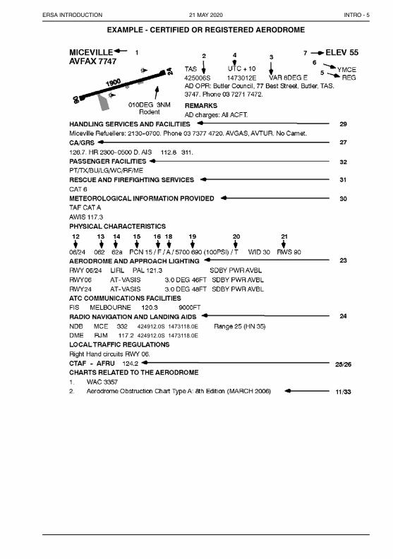
EXAMPLE - CERTIFIED OR REGISTERED AERODROME
424912.0S 1473118.0E424912.0S 1473118.0E
425006S 1473012E
INTRO - 521 MAY 2020
21 MAY 20

ERSA INTRODUCTION
EXPLANATION1. NAMES1.1 Names are listed alphabetically.
2. GEOGRAPHIC LOCATIONS2.1 ARP Location is shown in degrees, minutes and seconds.
3. MAGNETIC VARIATION3.1 Variation is shown in degrees magnetic, rounded to the nearest whole number.
4. TIME CONVERSION4.1 As a combination of Local and UTC time is used throughout the ERSA, all published times
have the designation Local or UTC.4.2 Local time in Australia falls into three separate zones; Eastern Standard Time, which is
UTC plus 10 hours (UTC + 10), Central Standard Time, which is UTC plus 9.5 hours(UTC + 9.30), and Western Standard Time, which is UTC plus 8 hours (UTC + 8).
4.3 These times apply as follows:a. EST is used in the states of New South Wales, (except the Broken Hill area),
Queensland, Victoria, Tasmania and the Australian Capital Territory.b. CST is used in the state of South Australia, the Northern Territory and the Broken Hill
area.c. WST is used in the State of Western Australia.
4.4 The time conversion shown at figure 4 represents the number of hours to be added to UTC to obtain the standard time applicable at that location. Allowance should therefore be made for any daylight saving that may be in force. (Note that 9.30 indicates nine and a half hours).
4.5 NOTAM will be issued detailing revised hours of operation for those aeronautical facilities affected by local time changes during periods of daylight saving and which do not have such hours promulgated in AIP.
5. AERODROME USAGE CLASSIFICATION AND GENERAL CODESCERT Certified Aerodrome
PUBLIC AVBL all classes of OPS
PVT (PRIVATE) - PPR from Facility Operator
REG Registered Aerodrome
MIL (MILITARY) - PPR for civil OPS class
UNCR Uncertified or Unregistered
JOINT Civil/Military Aerodrome
GENERAL CODES Based on “General and Meteorological Abbreviations” found in AIP GEN.
6. LOCATION IDENTIFIER6.1 Shown by the 3, 4 or 5 letter aeronautical code.
Note: 3 letter codes are not necessarily those used by IATA.
INTRO - 621 MAY 2020
21 MAY 20

ERSA INTRODUCTION
7. ELEVATION7.1 AD ELEV is shown in FT. When the ELEV is sea level, it will be indicated as 00. When the
ELEV is BLW sea level, a minus sign will precede the figure. This figure is the ELEV of the highest point of the landing area AMSL.
8. OPERATING HOURS8.1 HR shown are in UTC unless otherwise stated.8.2 Hours of operation are shown where possible using the following codes:
AH After Hours
DLY Daily
EXC PH Except Public Holidays
FRI Friday
H+... .... MIN past the hour
H24 Continuous day and night service
HDS Hours of Daylight Saving
HJ Sunrise to Sunset
HN Sunset to Sunrise
HO Service available to meet operational requirements
HR Hours
HS Service available during HR of scheduled operations
JF Saturday, Sunday and public holidays
JO Monday to Friday (except public holidays)
MON Monday
O/R On Request
OT Other Times
PH Public Holidays
PN Prior Notice required
PPR Prior Permission Required
SAT Saturday
SUN Sunday
THU Thursday
TUE Tuesday
WED Wednesday
9. SECURITY9.1 An ASIC is a prerequisite for authorisation to have unescorted access to secure areas at
security controlled airports, unless otherwise exempted under the Aviation Transport Security Regulations 2005. Airports that do not host regular passenger transport (RPT) operations are exempt from ASIC requirements. The Department of Home Affairs (Home Affairs) maintains a list of security controlled airports which is available at www.homeaffairs.gov.au/about-us/our-portfolios/transport-security/air-cargo-and-aviation/aviation/airport-operators. Further information regarding ASICs can be found on the Home Affairs website: https://www.homeaffairs.gov.au/about-us/our-portfolios/transport-security/identity.ASIC Aviation Security Identification CardFBO Fixed Base Operator
10. AD OPERATORARO Aerodrome Reporting Officer
INTRO - 721 MAY 2020
21 MAY 20
ERSA INTRODUCTION
11. AERODROME OBSTACLE CHART TYPE A CHARTS11.1 Aerodrome operators are responsible for Type A Chart information, (and the currency of
this information), listed under aerodromes in FAC section. The Charts will be shown with an “Edition Number” and “Date”; e.g. RWY 12/30, Edition 6 - July 2002. The date shown is the date of the last survey.
12. RUNWAY DESIGNATION12.1 RWY are normally numbered in relation to their magnetic direction rounded off to the
nearest 10 degrees. Single runways are shown with the lower number on the left side. Parallel runways designated Left/Right are shown with the left runway listed first. Multiple runways are shown in ascending order from top to bottom.
13. RUNWAY BEARING13.1 RWY bearing is in Degrees Magnetic.
14. RUNWAY DIMENSIONS14.1 The RWY length is the physical length of the RWY (generally the higher of the two RWY
direction TORA). RWY lengths are shown as multiples of 100 FT (e.g. lengths of 6,950 FT to 7,049 FT are shown as 70, lengths of 7,050 FT to 7,149 FT are shown as 71).
14.2 SURFACE. Runway surface is shown as follows:
a or A asphalt or bitumen;
b or B concrete;
c or C other surfaces (always to be qualified by a note).
15. PAVEMENT STRENGTHS15.1 The ICAO standard method of reporting pavement strength known as Aircraft Classification
Number/Pavement Classification Number (ACN/PCN) has been incorporated.Notes:
1. Pavement strength data for Military aerodromes is tabulated in FIHA section AD 1.1.2. Omission of pavement strength indicates that the RWY is unrated. See AIP AD 1.1 Section 7 for operating limitations.
16. PAVEMENT TYPE FOR ACN-PCN DETERMINATIONPavement type Code
Rigid pavement R
Flexible pavement F
17. PAVEMENT CONCESSIONS FOR ADF AERODROMES17.1 Users requiring a pavement concession for a DOD AD are to contact the Civil Engineering
Section of the Directorate of Estate Engineering Policy (EEP), within the Estate and Infrastructure Group (E&IG), on the following numbers:
Mobile +61 405 228 962
Phone +61 2 6266 8114
18. SUBGRADE STRENGTH CATEGORYSubgrade strength category CodeHigh strength AMedium strength BLow strength CUltra low strength D
INTRO - 821 MAY 2020
21 MAY 20
ERSA INTRODUCTION
19. MAXIMUM ALLOWABLE TYRE PRESSURE19.1 Weight and tyre pressure limits are shown in KG and kPa (PSI) in the format 5700 450(65)
and are gross limits, i.e. an ACFT may use that part of the movement area if the weight and tyre pressure are BLW the figures shown at the time of the operation. If the limitation is based on MTOW, this will be shown in the format MTOW 5700 KG, precluding an ACFT with MTOW in excess of the figure quoted FM OPR on the area specified.
19.2 Weight or tyre restrictions on RWY, TWY and aprons are shown in the remarks.19.3 For aircraft less than or equal to 5,700KG maximum takeoff mass: report maximum
allowable tyre pressure in kPa (PSI).19.4 For aircraft greater than 5,700KG maximum take-off mass: report maximum allowable tyre
pressure, as part of pavement strength rating, in accordance with the following code:MAX Allowable Tyre Pressure Category CodeHigh: No pressure limit WMedium: pressure limited to 1.50MPa XLow: Pressure limited to 1.00MPa Y1Low: Pressure limited to 0.80MPa Y2Very Low: Pressure limited to 0.50MPa Z1MPa = 1,000kPa
20. EVALUATION METHODEvaluation method CodeTechnical evaluation: representing a specific study of the pavement characteristics and application of pavement behaviour technology
T
Using aircraft experience: representing a knowledge of the specific typeand mass of aircraft satisfactorily being supported under regular use
U
21. RUNWAY SLOPE, RUNWAY STRIP WIDTH (RWS)21.1 SLOPE on RWY quoted is the difference BTN the MAX and the MNM ELEV along the RCL
divided by its length and expressed as a percentage to the nearest one-tenth of a percent. The “down” slope and its direction are tabulated in all cases, e.g., “0.8% down to SE”. Where significant slope variations occur, additional data may be shown in notices, e.g. “E end level, centre section 0.5% down to W, W end 0.1% down to E”.
21.2 RWS: is the width FM side to side which contains the RWY, the graded and ungraded portions of the RWS, shown in metres only. The GRADED portion of the RWS is defined by boundary markers and is graded to alleviate damage to an ACFT in the event that it runs off the RWY. The UNGRADED portion of the RWS is free of upstanding objects but may contain depressions, trenches, etc.
22. ARRESTING SYSTEMS22.1 Systems, other than those detailed BLW, will be shown as A-Gear and amplified by a note.
a. Tensioned Hookcable Arresting Systems:(i) BAK 12 HOOKCABLE AAS.The BAK 12 AAS is a bi-directional Hookcable AAS.
Energy is absorbed by a rotary friction braking system which is connected to the runway hookcable by a nylon tape. MAX tape runout is 365(1,200 FT). MAX energy absorption is 98.5 million FT LB. MNM rewind time is 3 minutes (nominal). Cycle rate for fighter type ACFT arrests is 12 ACFT per hour (nominal).
(ii) BAK 14.The BAK 14 is a spring/pneumatic system used for raising and lowering an AAS hookcable from and into the runway. BAK 14 systems are installed, in conjunction with BAK 12 hookcables, at YSRI, YWLM, YAMB, YBTL, YPDN, YPED and YPTN and YPEA. Normally selected up at departure end for arrestable ACFT OPS. ACFT captains are to request “Cable Down” or alternatively request “Approach End Cable Up” if required.
CAUTION: In the event of power and or pneumatic failure, APCH/DEP end cable will rise to a height of 100MM (4IN) and remain until failure rectified.
INTRO - 921 MAY 2020
21 MAY 20
ERSA INTRODUCTION
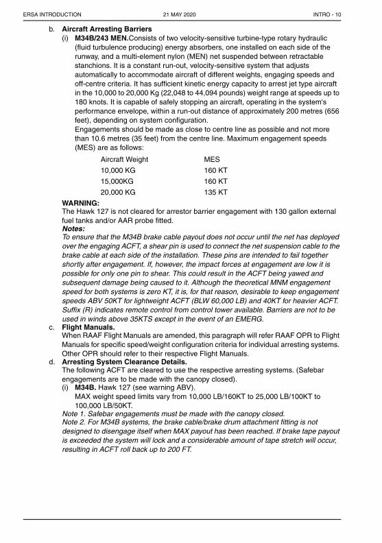
b. Aircraft Arresting Barriers(i) M34B/243 MEN.Consists of two velocity-sensitive turbine-type rotary hydraulic
(fluid turbulence producing) energy absorbers, one installed on each side of the runway, and a multi-element nylon (MEN) net suspended between retractable stanchions. It is a constant run-out, velocity-sensitive system that adjusts automatically to accommodate aircraft of different weights, engaging speeds and off-centre criteria. It has sufficient kinetic energy capacity to arrest jet type aircraft in the 10,000 to 20,000 Kg (22,048 to 44,094 pounds) weight range at speeds up to 180 knots. It is capable of safely stopping an aircraft, operating in the system's performance envelope, within a run-out distance of approximately 200 metres (656 feet), depending on system configuration.Engagements should be made as close to centre line as possible and not more than 10.6 metres (35 feet) from the centre line. Maximum engagement speeds (MES) are as follows:
Aircraft Weight MES
10,000 KG 160 KT
15,000KG 160 KT
20,000 KG 135 KT
WARNING:The Hawk 127 is not cleared for arrestor barrier engagement with 130 gallon external fuel tanks and/or AAR probe fitted.Notes:To ensure that the M34B brake cable payout does not occur until the net has deployed over the engaging ACFT, a shear pin is used to connect the net suspension cable to the brake cable at each side of the installation. These pins are intended to fail together shortly after engagement. If, however, the impact forces at engagement are low it is possible for only one pin to shear. This could result in the ACFT being yawed and subsequent damage being caused to it. Although the theoretical MNM engagement speed for both systems is zero KT, it is, for that reason, desirable to keep engagement speeds ABV 50KT for lightweight ACFT (BLW 60,000 LB) and 40KT for heavier ACFT. Suffix (R) indicates remote control from control tower available. Barriers are not to be used in winds above 35KTS except in the event of an EMERG.
c. Flight Manuals.When RAAF Flight Manuals are amended, this paragraph will refer RAAF OPR to Flight Manuals for specific speed/weight configuration criteria for individual arresting systems. Other OPR should refer to their respective Flight Manuals.
d. Arresting System Clearance Details.The following ACFT are cleared to use the respective arresting systems. (Safebar engagements are to be made with the canopy closed).(i) M34B. Hawk 127 (see warning ABV).
MAX weight speed limits vary from 10,000 LB/160KT to 25,000 LB/100KT to 100,000 LB/50KT.
Note 1. Safebar engagements must be made with the canopy closed.Note 2. For M34B systems, the brake cable/brake drum attachment fitting is not designed to disengage itself when MAX payout has been reached. If brake tape payout is exceeded the system will lock and a considerable amount of tape stretch will occur, resulting in ACFT roll back up to 200 FT.
INTRO - 1021 MAY 2020
21 MAY 20

ERSA INTRODUCTION
22.2 BAK 12 Hookcable.a. All hook equipped ACFT providing the weight and speed of the ACFT are within the
parameters specified in the ACFT flight manual. For 1,200FT runout systems with synchronised pressure of 2,000 PSI at 780 RPM, general parameters are:(i) Maximum engagement AUW is 95,000LB (43,180KG).(ii) Maximum engagement speed at 95,000LB is 160KT.(iii) Maximum engagement speed is 190KT.(iv) Maximum AUW at 190 KT is 65,000LB (29,550KG).(v) Minimum engagement AUW is 8,000LB(3,650KG)
b. Trampling (Roll Over) Clearances BAK 12/14This section is under review.Pilots should refer to the Pilot Operator Handbook or Flight Manual for specific restrictions for each ACFT. In the absence of any reference to trampling in either the Handbook or Manual, trampling is not authorised.Note: Close formation trampling of the hookcable is not permitted. MNM time BTN successive ACFT trampling the hookcable is five seconds.
c. Location of Arresting Systems(i) The arresting systems are shown as located on the RWY. The middle portion of the
RWY is indicated by a line and the distance of the arresting system from the end of the RWY (or into the overrun) on the end on which the system is located is indicated (in feet) in brackets under the applicable system. CAUTION: Up to 15 minutes notice may be RQ for rigging arresting gear for APCH end engagement.
RWY 15 M34B (R) BAK 12/14(*1)
-------- BAK 12/14 (*1)
M34B (R) RWY 33
62 (203) OVRN
464 (1,521) 464 (1,521) 62 (203) OVRN
*1. Hookcable normally rigged across DEP end of RWY for arrestable ACFT OPS.*2. Suffix (R) indicates remote control from control Tower available.*3. Suffix (B) indicates the arresting systems allows bi directional engagement.
23. AERODROME AND APPROACH LIGHTINGNOTE: NO STAND-BY POWER AVAILABLE UNLESS ANNOTATED.
23.1 Unless otherwise specified, runway lights include runway edge, threshold and runway end lights, and stopway lights where stopways are provided. Lighting is listed by the abbreviations shown below.ABN Aerodrome Beacon
AFRU + PAL (FREQ) Aerodrome Frequency Response Unit plus PAL
AT-VASIS Abbreviated (Singled Sided) T pattern Visual Approach Slope Indicator System
FDL Fixed Distance Lighting
HIAL-CAT I High Intensity Approach Lights - CAT I
HIAL-CAT II or III High Intensity Approach Lights - CAT II or III
HIOL High Intensity Obstacle Lights (flashing white)
HIRL High Intensity Runway Lights (5 or 6 stages of intensity)
HSL Hold Short Lights used in conjunction with Land and Hold Short Operations (LAHSO)
LIOL Low Intensity Obstacle Lights (steady red)
LIRL Low Intensity Runway Lights (single stage of intensity)
MIOL Medium Intensity Obstacle Lights (flashing red)
MIRL Medium Intensity Runway Lights (three stages of intensity)
PAL (FREQ) Pilot Activated Aerodrome Lighting (with dedicated frequency)
PAPI PAPI Visual Approach Slope Indicator System
INTRO - 1121 MAY 2020
21 MAY 20

ERSA INTRODUCTION
PAPI# PAPI commissioned by ground survey (not available to RPT jets). Report any anomalies to AD OPR.
PTBL Portable or temporary lights (flares or battery)
RCGL Runway Circling Guidance Lights
RCLL Runway Centre Line Lights
REDL Runway Edge Lights
RGL Runway Guard Lights (Alternating Flashing Yellow)
RLLS Runway Lead-in Lighting
RTIL Runway Threshold Identification Lights (flashing white)
RTZL Runway Touchdown Zone Lights
SALS Simple Approach Lighting System
SDBY PWR Standby Power
SFL Sequenced Flashing Lights
STWL Stopway Light(s)
T -VASIS T pattern Visual Approach Slope Indicator System
Taxiways Centre line lights are green and edge lights are blue
23.2 Lights may be described by the following abbreviations: ALTN Alternating
B Blue
FLG Flashing
G Green
GP FLG (number) Group flashing (number)
OCC Occulting
R Red
W White
Y Yellow
23.3 Lighting provided by kerosene lamps may not be available during fire ban periods, except in emergencies.
23.4 Operation of VHF Pilot Activated Lighting (PAL)a. ON DEPARTURE: Before taxib. ON ARRIVAL: Within 15 NM of AD, and at or ABV LSALT select the appropriate VHF
FREQ:
(i) Transmit pulse must be between 1 and 5 SECS(ii) Three pulses must be transmitted within 25 SECS. Ensure that the third pulse ends
before the 25th second.(iii) Break between transmissions can be more or less than 1 SEC - (no limit)
Lights to illuminate for a minimum of 30 MINS. If not- keep transmitting 3 SEC pulses- check frequency
(iv) When runway lights are about to extinguish, the wind indicator light will flash continuously. REPEAT OPERATING PROCEDURE.
INTRO - 1221 MAY 2020
21 MAY 20

ERSA INTRODUCTION
23.5 Aerodrome Frequency Response Unit With PAL Option (AFRU + PAL)a. PAL operation may be provided as an optional function of the AFRU (see CTAF section)
on the associated aerodrome CTAF. Aerodrome lighting enabled by AFRU + PAL is AVBL only during night hours or at other times of low natural light levels. During periods of daylight, when the light intensity is above a preset level, the system will not activate the lights.
b. Where a discrete PAL FREQ is also provided, actuation of the aerodrome lights may be effected either by using the PAL system on the discrete PAL FREQ or the AFRU + PAL system on the CTAF.
c. On receipt of the required ACFT transmission the AFRU will operate the aerodrome lighting circuitry (RWY and wind indicator lights). The AFRU will transmit the standard reply (the aerodrome name and CTAF) immediately followed by the additional confirming message, “RUNWAY LIGHTS ON”. If the lights do not illuminate, the AFRU will transmit the message, “NO RUNWAY LIGHTS”. In this case, pilots should key the required transmission again or, alternatively, change to the PAL FREQ and operate the lights via the PAL.
d. AFRU + PAL required transmission is:
Note: Transmission to be completed in 5 seconds. If unsuccessful repeat transmission.e. After actuation, the aerodrome lights will remain illuminated for 30 minutes. After 20
minutes, the windsock lights will flash at 1 second intervals and the AFRU will transmit the message, “RUNWAY LIGHTS 10 MINUTES REMAINING”. At any time, keying of the required transmission will reset the lights for a period of 30 minutes.
f. Aerodromes which have the AFRU + PAL option will have the entry “PAL + AFRU” included under the “LIGHTING” heading.
23.6 T-VASIS/AT-VASISa. The T-VASIS consists of twenty light units symmetrically disposed about the RWY
centre line in the form of two wing bars of four light units each, with bisecting longitudinal lines of six lights.
b. The AT-VASIS consists of ten light units arranged on one side of the RWY in the form of a single wing bar of four light units with a bisecting longitudinal line of six lights.
c. The crossbar represents 'on glide-slope' and deviations appear as one, two or three lights ABV or BLW the crossbar. The sensitivity is similar to flying within the 'three-dot-up' or 'three-dot-down' positions of an ILS glide path.
d. The T-VASIS is designed so that with only the crossbar lights visible, the glide-slope is 3DEG and the pilot's eye-height over the THR is APPROX 47 FT. The height quoted in FT is the MNM EYE HEIGHT at THR, i.e. the lowest height at which an “on glide path” indication will be seen. If increased eye-height over the THR is required (e.g. long/wide bodied ACFT) this can be achieved by flying the approach with the crossbar and one or more of the 'fly-down' lights visible as required. In this manner variable vertical distances between the pilot's eyes and the THR can be obtained.
e. APPROACH SLOPE INDICATION EYE HEIGHT ABOVE THRESHOLD
THREE LIGHTS FLY UP Ground level to 7FTTWO LIGHTS FLY UP 8FT to 25FTONE LIGHT FLY UP 25FT to 41FTON GLIDE SLOPE 49FTONE LIGHT FLY DOWN 57FT to 75FTTWO LIGHTS FLY DOWN 75FT to 94FTTHREE LIGHTS FLY DOWN 94FT to 176FT
INTRO - 1321 MAY 2020
21 MAY 20

ERSA INTRODUCTION
The previous dimensions may vary by 15 FT, depending on the location of the system as dictated by siting requirements.
23.7 The initial intensity of the system is determined by ATS, but may be varied at the request of the pilot.
23.8 PAPIa. The PAPI system consists of a wing bar of 4 (or paired single lamp) lights equally
spaced located on the left side of the RWY unless it is physically impracticable to do so.b. The height quoted in FT is the MNM EYE HEIGHT at THR, i.e. the lowest height at
which an “on glide path” indication will be seen.c. The wing bar of a PAPI is arranged in such a manner that a pilot making an APCH will:
(i) when on or close to the APCH slope, see the two units nearest the RWY as red and the two units farthest from the RWY as white;
(ii) when ABV the approach slope, see the one unit nearest the RWY as red and the three units farthest from the RWY as white; and when further above the APCH slope, see all the units as white; and
(iii) when BLW the APCH slope, see the three units nearest the RWY as red and the unit farthest from the RWY as white; and when further BLW the APCH slope, see all the units as red.
24. RADIO NAVIGATION AND LANDING AIDS24.1 Distance Measuring Equipment
a. The DME system uses the channels designated in ICAO Annex 10 for operation with the VOR FREQ selected for the same AD. This “pairing” of the VOR and the DME thus permits airborne equipment suitably designed, to display both DME and VOR INFO by the selection of only the VOR FREQ.
b. TACAN has also been installed at a number of MIL and joint user AD and the DME element of these installations is AVBL to civil ACFT equipped with 1000 DME. This element will normally be paired with VOR where both facilities are established at a joint user AD/WI the ICAO Annex 10 collocation DIST RQMNTS.
c. The availability of associated VOR and DME INFO is shown in ERSA, ERC, AC and on FLIP Terminal charts in one of the FLW forms.
VOR/DME 112.7
VOR 113.7
DME 112.7/74X
TACAN 84
24.2 Bearings, Distance and Hours of AidsBearings and distance given is from the aid to the ARP, (shown in DEG MAG and NM) unless noted that the bearing and distance is to the appropriate RWY THR. Navigation aids HR of OPS H24 unless otherwise shown.
24.3 Hazard Beacons (HBO)Hazard Beacons are utilised as an aid to navigation for obstacle avoidance in the vicinity of aerodromes. HBO are either HIOL or MIOL (see Aerodrome and Approach Lighting).
INTRO - 1421 MAY 2020
21 MAY 20

ERSA INTRODUCTION
25. COMMON TRAFFIC ADVISORY FREQUENCY (CTAF)25.1 Frequencies to be used for operations at aerodromes are listed against locations under the
heading “CTAF”.25.2 Carriage of serviceable VHF radio, and being qualified to use it, are mandatory when
operating at, or in the vicinity of, all uncontrolled certified, registered and military aerodromes. However, a pilot may operate an aircraft with an unserviceable VHF radio at, or in the vicinity of, an uncontrolled aerodrome where the carriage of serviceable VHF radio is normally required if a radio failure occurs during the flight or if the purpose of the flight is to take the radio to a place where it can be repaired. The pilot may continue to land at the aerodrome provided the pilot activates the aircraft's anti-collision lights, landing lights and transponder (if any) whilst within the vicinity of the aerodrome and, if arriving at the aerodrome, joins the circuit on the crosswind leg.Note: A pilot should avoid planning to arrive at or depart from an aerodrome for radio repairs during the known hours of scheduled regular public transport (RPT) operations. For aerodromes where there is a UNICOM or CA/GRS, pilots should, by alternative means, where possible, make contact and advise intentions before conducting operations.
25.3 A pilot may operate an aircraft that is not equipped with a serviceable aircraft VHF radio, or which is equipped with such a radio but which the pilot is not qualified to use, to or from an uncontrolled aerodrome at which the carriage of radio is normally required if the aircraft is flown:a. In VMC by day, andb. Arrives or departs in company with another aircraft which is radio-equipped and flown
by a radio-qualified pilot which will allow the latter to make radio calls on behalf of both aircraft. The radio equipped aircraft should be manoeuvred to keep the no radio aircraft at a safe distance and in sight at all times in order to accurately report its position.
25.4 Pilots of inbound traffic should monitor and communicate as appropriate on the designated CTAF from 10 miles to landing. Pilots of departing aircraft should monitor/communicate on the appropriate frequency from start-up, during taxi, and until 10 miles from the airport unless local procedures require otherwise.
25.5 Pilots of aircraft conducting other than arriving or departing operations at altitudes normally used by arriving and departing aircraft should monitor/communicate on the appropriate frequency while within 10 miles of the airport unless required to do otherwise by local procedures. Such operations include parachute jumping/dropping, en route, practicing manoeuvres, etc.
26. AERODROME FREQUENCY RESPONSE UNIT (AFRU)26.1 An aerodrome frequency response unit will provide an automatic response when pilots
transmit on the traffic frequency for the particular aerodrome, normally the CTAF. It will assist in indicating inadvertent selection of the incorrect VHF frequency when pilots operate into uncontrolled aerodromes.
26.2 At locations where an AFRU is installed, the entry “AFRU” is included in the CTAF heading.26.3 When an ACFT operating within approximately 20 to 30 NM of the AFRU makes a
transmission of 2 secs duration or more on the aerodrome FREQ, the AFRU will automatically respond with one of the following types of transmissions:a. If no other ACFT transmissions have been received within the previous 5 minutes, a
pre-recorded voice message comprising aerodrome identification followed by “CTAF”; or
b. If any ACFT transmissions have been received within the previous 5 minutes, a low volume 300 millisecond tone burst.
26.4 The AFRU will also detect ACFT transmissions which consist of three sequential carrier bursts within a five second period (i.e. three microphone clicks) and respond with the prerecorded voice message, regardless of aircraft radio transmission activity in the last 5 minutes. Further information can be found in AIP Book.
INTRO - 1521 MAY 2020
21 MAY 20

ERSA INTRODUCTION
27. CERTIFIED AIR/GROUND RADIO SERVICE (CA/GRS)27.1 A CA/GRS is an aerodrome radio information service on the CTAF. The service is an
information service, not an air traffic service. Pilots retain full responsibility to decide whether to accept and use the information provided. A CA/GRS provides the following information:a. Confirmation of frequency selection by pilots, by means of the operator's response to a
pilot's broadcast when taxiing at an aerodrome or inbound to an aerodrome.b. Known, relevant traffic on the CTAF and on the manoeuvring area of the aerodrome to
an aircraft when taxiing for departure or inbound to an aerodrome.c. Weather conditions at the aerodrome. The weather information which may be advised
is runway favoured by wind or for noise abatement, runway surface conditions, wind direction and speed, visibility and present weather, estimated cloud base, surface temperature, and aerodrome QNH. This information will be provided by means of an Automatic Aerodrome Information Service (AAIS) broadcast on a discrete frequency (similar to ATIS) during CA/GRS OPR HR or on request to the CA/GRS. QNH provided by a CA/GRS or AAIS may be used to reduce DAP IAL MDA in accordance with AIP ENR 1.5, QNH Sources.
d. Other local information.e. Emergency services call-out, if requested by the pilot in an emergency.
27.2 At those aerodromes where a Certified Air/Ground Radio Service is provided, the abbreviation “CA/GRS” is included in the aerodrome entry, together with the designated broadcast area and frequency, the AAIS frequency and any location specific procedures, service's hours of operation and callsign.
28. UNICOM28.1 UNICOM (Universal Communications) is a service provided on specific frequencies to
enhance the value of information normally available about a non controlled aerodrome. UNICOM is not provided by Airservices Australia.
28.2 At locations where a UNICOM has been established, the entry giving details about the service, such as the callsign, hours of operation or any particular service provided, will be shown beneath the Handling Services and Facilities entry.
28.3 UNICOM operators are required to obtain a licence from The Australian Communications Authority and frequency band approval must come from Airservices Australia, prior to the entry being placed in this document.
29. HANDLING SERVICES AND FACILITIES29.1 Replenishment facilities are listed using the following codes. The left hand column contains
the code symbol, the main body gives a brief description and where applicable, finally (in brackets) the Australian designation.CAUTION: Due to changes without notice, accuracy of REPLEN entries under “Ground Services”, cannot be guaranteed.When information is received from the relevant aerodrome authority, a NOTAM will be issued notifying changes to refuelling information. However, Airservices Australia takes no responsibility for the accuracy or completeness of refuelling information.
FUEL
AVGAS aviation gasoline, grade 100/130 (AVGAS 100/130) (SG 0.72)
F34 aviation turbine kerosene (JET A1 with FSII (S-1745))(-47DEG C freeze point), (SG 0.775 - 0.840)
JET A1 aviation turbine kerosene (JET A1 without FSII (S-1745))(-47DEG C freeze point) (SG 0.775 - 0.840)
F40 aviation turbine gasoline (AVTAG with FSII (S748) (low vapour pressure) (SG 0.80)
F44 aviation turbine kerosene (AVCAT 48)(high flash point with FSII (S-1745)) (-46DEG C freeze point) (SG 0.788 - 0.845)
INTRO - 1621 MAY 2020
21 MAY 20
ERSA INTRODUCTION
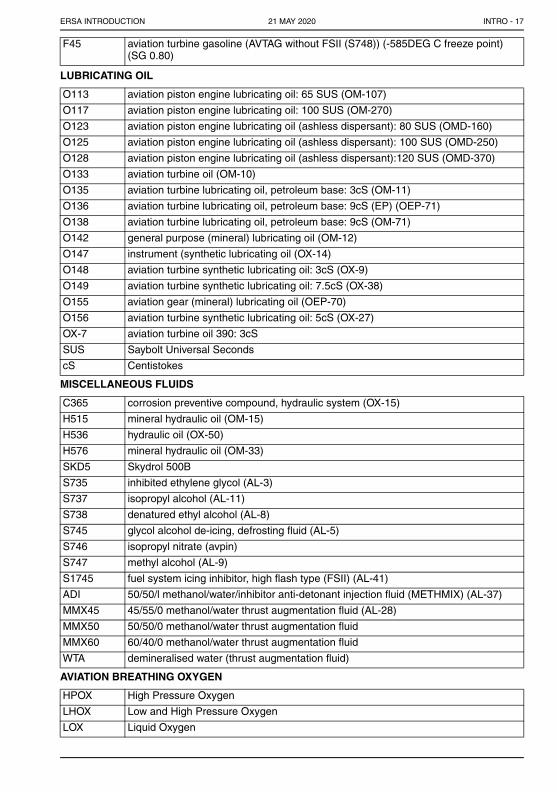
F45 aviation turbine gasoline (AVTAG without FSII (S748)) (-585DEG C freeze point) (SG 0.80)
LUBRICATING OIL
O113 aviation piston engine lubricating oil: 65 SUS (OM-107)
O117 aviation piston engine lubricating oil: 100 SUS (OM-270)
O123 aviation piston engine lubricating oil (ashless dispersant): 80 SUS (OMD-160)
O125 aviation piston engine lubricating oil (ashless dispersant): 100 SUS (OMD-250)
O128 aviation piston engine lubricating oil (ashless dispersant):120 SUS (OMD-370)
O133 aviation turbine oil (OM-10)
O135 aviation turbine lubricating oil, petroleum base: 3cS (OM-11)
O136 aviation turbine lubricating oil, petroleum base: 9cS (EP) (OEP-71)
O138 aviation turbine lubricating oil, petroleum base: 9cS (OM-71)
O142 general purpose (mineral) lubricating oil (OM-12)
O147 instrument (synthetic lubricating oil (OX-14)
O148 aviation turbine synthetic lubricating oil: 3cS (OX-9)
O149 aviation turbine synthetic lubricating oil: 7.5cS (OX-38)
O155 aviation gear (mineral) lubricating oil (OEP-70)
O156 aviation turbine synthetic lubricating oil: 5cS (OX-27)
OX-7 aviation turbine oil 390: 3cS
SUS Saybolt Universal Seconds
cS Centistokes
MISCELLANEOUS FLUIDS
C365 corrosion preventive compound, hydraulic system (OX-15)
H515 mineral hydraulic oil (OM-15)
H536 hydraulic oil (OX-50)
H576 mineral hydraulic oil (OM-33)
SKD5 Skydrol 500B
S735 inhibited ethylene glycol (AL-3)
S737 isopropyl alcohol (AL-11)
S738 denatured ethyl alcohol (AL-8)
S745 glycol alcohol de-icing, defrosting fluid (AL-5)
S746 isopropyl nitrate (avpin)
S747 methyl alcohol (AL-9)
S1745 fuel system icing inhibitor, high flash type (FSII) (AL-41)
ADI 50/50/l methanol/water/inhibitor anti-detonant injection fluid (METHMIX) (AL-37)
MMX45 45/55/0 methanol/water thrust augmentation fluid (AL-28)
MMX50 50/50/0 methanol/water thrust augmentation fluid
MMX60 60/40/0 methanol/water thrust augmentation fluid
WTA demineralised water (thrust augmentation fluid)
AVIATION BREATHING OXYGEN
HPOX High Pressure Oxygen
LHOX Low and High Pressure Oxygen
LOX Liquid Oxygen
INTRO - 1721 MAY 2020
21 MAY 20

ERSA INTRODUCTION
LPOX Low Pressure Oxygen
OXRB Oxygen Replacement Bottles (type of aircraft specified)
POWER UNITS - (ELECTRIC)
E1 28VDC Battery Cart
E2 28VDC 2.2KW
E3 28VDC 7.5KW
E4 28VDC 10KW
E5 28VDC 15KW
E6 Rectifier starting 28VDC 6KW/30KW Peak
E7 Underground Power, 28VDC 15KW, 120/208VAC 50KVA
E8 28VDC 10KW, 120/208VAC 60KVA
E9 28VDC 45KW, 120/208VAC 60KVA
E10 28VDC 14KW, 120/208VAC 45KVA
E11 28VDC 15KW, 120/208VAC l5KVA
E12 15KW, 120/208VAC 75KVA 28VAC
E13 28VAC 15KW, 120/208VAC 90KVA
E14 28VDC 22.5KW, 124/208VAC 30KVA
E15 28VDC 25KW, 124/208VAC 30KVA
E16 28VDC 45KW, 124/208VAC 60KVA
POWER UNITS - (AIR)
A1 Low pressure air starter (40PSI)
PRESAIR Compressed air replenishment: 3000PSI or higher AVBL
CREDIT DETAILS
Credit cards accepted by Refuellers
AC Access Card
DC Diners Club
V Visa Card
MC Master Card
AMEX American Express
30. METEOROLOGICAL INFORMATION PROVIDED
AD WRNG Aerodrome Warning
AWIS* Aerodrome Weather Information Service
METAR/SPECI Routine and Special Aerodrome Observations
MO Meteorological Office
MWO Meteorological Watch Office
TAF CAT TAF Category - Refer to AIP Book for details
TTF Trend Forecast
WATIR Weather and Terminal Information Reciter
WS WRNG Windshear Warning
* AWIS can be received either on broadcast or phone or both and is indicated in the FAC section by the publication of the phone number the frequency or both.Some AWIS on broadcast require a one second pulse or three one second pulses to activate.
INTRO - 1821 MAY 2020
21 MAY 20

ERSA INTRODUCTION
31. RESCUE AND FIREFIGHTING SERVICES31.1 RFFS FACILITIES are allocated a CAT within the range of CAT 1 to CAT 10 with minimum
water quantity and RFFS vehicle requirements as per the table. Note that the figures below refer to quantities and discharge rates for water and different minimum quantities and discharge rates apply to other extinguishing agents. Categories are allocated to give a reasonable chance of rescue at a serious accident, with the probability of survivors, involving an ACFT within the group. Military users refer DI(AF)OPS for specific requirements/conditions applicable to Military airfields.
CAT 1 2 3 4 5 6 7 8 9 10
MNM water quantity RQ
230 670 1200 2400 5400 7900 12100 18200 24300 32300
MNM discharge rate RQ (L/MIN)
230 550 900 1800 3000 4000 5300 7200 9000 11200
MNM number of RFFS vehicles RQ (CIV only)
1 1 1 1 1 2 3 3 3 3
31.2 AIRSERVICES RFFS - ICAO/CASA STANDARD31.2.1 This chart indicates the (ICAO) “minimum” useable amounts of extinguishing agents
applicable to each RFFS category.
Category Vehicle Water Discharge Rate Complementary Agent(Dry Chemical)
5 1 5400 3000 l/m 180KG
6 2 7900 4000 l/m 225KG
7 2 12100 5300 l/m 225KG
8 3 18200 7200 l/m 450KG
9 3 24300 9000 l/m 450KG
31.3 Airservices Water Rescue Service (WRS)a. Airservices Australia RFFS provides a water rescue service at certain aerodromes as
specified in the relevant aerodrome’s RFFS entry in ERSA. This service consists of rescue boats which provide a first response to an ACFT incident in water areas to deploy flotation platforms, pending the arrival of a larger, second stage response under an aerodrome AEP.
b. The water rescue service does not constitute a part of RFFS category however, any subsequent non availability of the complete WRS will generate notification processes compatible with a contingency plan involving other emergency Agencies (and ATS) at that aerodrome location.
32. PASSENGER FACILITIES32.1 The following codes are used for the display of PUBFAC data in ERSA:
AC ACCOMMODATION PT PUBLIC TELEPHONE
BU BUS TO TOWN RF REFRESHMENT
HC HIRE CAR WC TOILETS
LG PASSENGER LOUNGE TX TAXI
ME MAINTENANCE
32.2 Where relevant and available other brief information, e.g. telephone numbers, is included alongside the facility.
INTRO - 1921 MAY 2020
21 MAY 20

ERSA INTRODUCTION
32.3 In many instances services such as taxi or hire car are not available at the aerodrome itself, but need to be contacted by telephone after arrival. Where availability of refreshments is indicated there is usually some limitation on the hours, and may vary from full meal service to a drink vending machine. Buses are often scheduled to meet RPT aircraft only. AIRSERVICES ACCEPTS NO RESPONSIBILITY FOR THE ACCURACY OF PUBFAC DATA.
33. WAC CHART REFERENCE33.1 The WAC Chart on which the AD can be found.
34. CHANGES IN AERODROME INFORMATION34.1 Changes in AD INFO will be promulgated by NOTAM to the extent indicated BLW:
a. Co-ordinates/LCA of the AD - if the PSN is altered by more than 0.5 NM;b. ELEV of an AD - alterations in excess of:
(i) 20FT for AD with instrument approaches(ii) 100FT for other AD;
c. RWY/Strip bearing and number - alterations which cause a change in RWY number; and
d. Declared Distances, Supplementary TKOF Distances and Dimensions of RWY and RWS -(i) length - 10(33FT) decrease or 30(98FT) increase.(ii) width - any change.
e. TODA Gradient - any change in gradient in excess of 0.05%.34.2 NOTAM advising of reductions in RWY length due to obstacles associated with WIP will
include the LCA of the obstacle(s). Some NOTAM may include additional obstacle information intended solely to amend the obstruction chart issued for that AD.a. The work is on the movement area, and/orb. Obstacles infringe clearance surfaces, and the affected area cannot be restored within
10 MIN of an ACFT’s indicated intention to use the area.Although maintenance staff are RQ to watch for ACFT, pilots OPR into non-controlled AD may need to attract the attention of such staff before LDG or TKOF.
35. PRD ACRONYM LIST
ACFR Australian Centre for Field Robotics, Sydney University
AD OPR Aerodrome Operator
AFHQ AFHQ Air Force Headquarters
ANSTO Australian Nuclear Science and Technology Organisation
AsA Airservices Australia
BCP Base Command Post
CASA OAR Civil Aviation Safety Authority, Office of Airspace Regulation
CSIG Corporate Services Infrastructure Group
CSIRO Commonwealth Scientific and Industrial Research Organisation
DEFENCE Department of Defence (Switchboard)
DO Duty Officer
DOTAM Director of Training Area Management
DS Defence Support
EODF Explosive Ordnance Defence Flight
FLT Flight
FLTCDR Flight Commander
GBRMPA Great Barrier Reef Marine Park Authority
HQ Headquarters
INTRO - 2021 MAY 2020
21 MAY 20

ERSA INTRODUCTION
JACC Joint Airspace Control Cell
MHQ Maritime Headquarters
NDTAM Non Defence training Area Manager
OC Officer Commanding
OIC Officer In Charge
OPSO Operations Officer
OPS WO Operations Warrant Officer
RAAF Royal Australian Air Force
RCO Range Control Officer
RSU Radar Support Unit
SRPSU School of Radio Physics, Sydney University
WTF Weapons Training Flight
WTO Weapons Training Officer
RUNWAY DISTANCES LEGENDNote: TORA/TODA information in separate sectionBUTLER
RWY (CN) TORA TODA ASDA LDA
05 3 2515(8252) 2575(8449)(1.98%) 2515(8252) 2515(8252)
23 3 2515(8252) 2575(8449)(1.20%) 2515(8252) 2515(8252)
Slope 0.62% down the SW. RWY WID 30, RWS WID 300, Graded 150
14 2 1000(3281) 1060(3478)(1.47%) 1000(3281) 1000(3281)
32 2 1000(3281) 1060)(3478)(2.65%) 1000(3281) 1000(3281)
Slope from ends 0.32% down to point 670M from NW end. RWY WID 30, RWS WID 90
SUPPLEMENTARY TKOF DIST:RWY 05 - 2389(7838)(1.6%) 2547(8356)(1.9%)RWY 32 - 897(2943)(2.5%)RWY 05 - TKOF FROM TWY A
1. DECLARED DISTANCES1.1 Declared distances in metres(feet) are tabulated for each RWY. They are:
a. TORA (TAKEOFF RUN AVAILABLE)The length of RWY declared available and suitable for the ground run of an ACFT taking off. (In most cases, this corresponds to the physical length of the RWY pavement.)
b. TODA (TAKEOFF DISTANCE AVAILABLE)The length of TKOF run available plus the length of any clearway (CWY) available.
c. ASDA (ACCELERATE-STOP DISTANCE AVAILABLE)The length of TKOF run available, plus the length of the stopway (SWY), if provided. (Any SWY length included shall be adequate for use by all ACFT which comply with the RWY strength rating.)
d. LDA (LANDING DISTANCE AVAILABLE)The length of RWY declared available and suitable for the ground run of an ACFT landing (LDG). (In most cases, this corresponds to the physical length of the RWY pavement.)
INTRO - 2121 MAY 2020
21 MAY 20

ERSA INTRODUCTION
1.2 RESA - Runway End Safety Area1.2.1 RESA is the cleared and graded area adjacent to the end of a RWY or SWY intended for
use in the event of an ACFT undershooting or overrunning the RWY. In Australia, a minimum RESA of 60M(197FT) is provided, except for RWY serving only code 1 RWY where 30M(99FT) is the minimum. The minimum RESA for a RWY serving jet RPT ACFT is 90M(295FT). Because of the requirement for a RESA, the declaring of less than the full RWY length to be available for TKOF or LDG is sometimes necessary.
1.3 Aerodrome Reference Code - Code Number (CN)1.3.1 A reference code number is provided for each RWY listed in the RDS (in brackets after
each RWY designation number). This code number indicates the maximum field length of the aeroplane that the RWY is designed for. Code numbers and associated field lengths are as follows:1 - Field length of less than 800M2 - Field length of 800M up to, but not including, 1200M3 - Field length of 1200M up to but not including 1800M.4 - Field length of 1800M and over.
1.3.2 Pilots should note that the field length of an aeroplane is based on the performance of an aeroplane during certification and is not related to the actual RWY length provided at an aerodrome.
1.3.3 Use the code number to determine the applicable standards of obstacle-clear approach gradients, take-off gradients and takeoff survey areas for the RWY. The code number is not intended to limit aircraft operations at an aerodrome. Aircraft operators and/or pilots must ensure that the published aerodrome information meets requirements for their aircraft operations.
1.4 Obstacle-Clear Approach Gradients1.4.1 The obstacle-clear approach gradient is normally based on the following standard:
a. the threshold is located at least 60M from the intersection of the obstacle-clear approach surface with the extended RWY centre line; and
b. obstacle-clear approach gradients of:(i) 5% for a code 1 RWY or MIL Visual APCH RWY up to 800M length,(ii) 4% for a code 2 RWY or MIL Visual APCH RWY 800M up to 1200M length,(iii) 3.3% for a code 3 and 4 RWY, and or MIL Visual APCH RWY 1200M up to 1800M
length,(iv) 2.5% for a MIL Visual APCH RWY 1800 M and over.(v) 3.3% for NPA Code 1, 2 or 3 RWY;(vi) 2% for NPA Code 4 and precision APCH RWY,(MIL RWYs: 2.0% for 3000M, then 2.5% until outer horizontal surface, then horizontal).
1.4.2 Any variation to the standard is explained in a note under the relevant declared distances entry.
1.5 Obstacle-Clear Takeoff Gradients1.5.1 Areas from the ends of runways, defined in accordance with the table below, are surveyed
for obstacles. The obstacle-clear takeoff gradient is based on the greatest vertical angle with the horizontal subtended by an obstacle within the surveyed area. This gradient information is shown in brackets immediately following the TODA information. Liaise with the AD OPR if obstacle information is required.
1.5.2 Supplementary Takeoff Distances Available (STODA) are shown for obstacle-clear takeoff gradients (within the same defined area) of 1.6%, 1.9%, 2.2%, 2.5%, 3.3% and 5% if the TODA gradient exceeds these figures and the resultant STODA is greater than 800M.
1.5.3 Where an existing fence or levee is located very close to the RWY end, the fence or levee may not be taken into account in the assessment of the obstacle-clear takeoff gradients for TODA and STODA purposes. In such cases, information of the height and location of the fence or levee will be provided in a note under the relevant declared distances entry.
INTRO - 2221 MAY 2020
21 MAY 20

ERSA INTRODUCTION
1.5.4 If the survey area is not in accordance with the table below, details of the actual obstacle survey area are provided below the relevant declared distances entry.
1.6 Takeoff Runway Survey Areas
Takeoff Climb Surface - Dimensions Take-off Runways Code Number
1 2 3 or 4 MIL
Length of inner edge 60M 80M 180M RWS WID
Minimum distance of inner edgefrom RWY end @
30M 60M 60M CWY DIST
Rate of divergence (each side) 10% 10% 12.5% 13.2%
Final Width 380M 580M 1200M1800M#
2518M
Overall length 1600M 2500M 15000M 15,000M$
# When the takeoff procedure includes changes of heading greater than 15DEG for operations conducted in IMC or VMC by night.@ The takeoff climb surface starts from the end of clearway if a clearway is provided.$3000M for RWYs < 1200M.SLOPE: on RWY quoted is the difference between the maximum and the minimum elevation along the centre line of the RWY divided by its length and expressed as a percentage to the nearest one-tenth of a percent. The “down” slope and its direction are tabulated in all cases, e.g. “0.8% down to SE”. Where significant slope variations occur, additional data may be shown in notices, e.g. “E end level, centre section 0.5% down to W, W end 0.1% down to E”.RWS WIDTH: is the width from side to side which contains the RWY, the graded and ungraded portions of the RWS, shown in metres only. The GRADED portion of the RWS may be defined by boundary markers and is graded to alleviate damage to an ACFT in the event that it runs off the RWY. The UNGRADED portion of the RWS is free of upstanding objects but may contain depressions, trenches, etc.1.7 Climb/Descent Gradient Graph1.8 Example: At a speed of 250KT (470KM/H), a gradient of 3% corresponds to a rate of
760FT/MIN (4M/SEC).
Climb/descent gradient (%) versus rate of climb/descent in metres/second (M/S) and feet/minute (FT/MIN) at speed in kilometres/hour (KM/H) & knots (KT).
INTRO - 2321 MAY 2020
21 MAY 20

This page is intentionally blank.