introduction to boards.pdf
TRANSCRIPT

Hardware Description Manual SmartAX MA5600 Multi-service Access Module Table of Contents
Huawei Technologies Proprietary
i
Table of Contents
Chapter 4 Introduction to Boards ................................................................................................ 4-1 4.1 About This Chapter ............................................................................................................ 4-1 4.2 Main Control Board—SCU................................................................................................. 4-1
4.2.1 Overview ................................................................................................................. 4-1 4.2.2 Front Panel.............................................................................................................. 4-2 4.2.3 Subboards ............................................................................................................... 4-3
4.3 Intelligence Service Unit—ISU........................................................................................... 4-5 4.3.1 Overview ................................................................................................................. 4-5 4.3.2 Front Panel.............................................................................................................. 4-5 4.3.3 Subboards ............................................................................................................... 4-7
4.4 64-Port ADSL2+ Service Board—ADEF/ADBF................................................................. 4-8 4.4.1 Overview ................................................................................................................. 4-8 4.4.2 Front Panel.............................................................................................................. 4-9
4.5 32-Port SHDSL Service Board—SHEA........................................................................... 4-11 4.5.1 Overview ............................................................................................................... 4-11 4.5.2 Front Panel............................................................................................................ 4-12
4.6 ATM Interface Board—AIUG ........................................................................................... 4-13 4.6.1 Overview ............................................................................................................... 4-13 4.6.2 Front Panel............................................................................................................ 4-14 4.6.3 Subboards ............................................................................................................. 4-15 4.6.4 DIP Switches of Subboard .................................................................................... 4-16
4.7 Ethernet Interface Board—EIUB...................................................................................... 4-17 4.7.1 Overview ............................................................................................................... 4-17 4.7.2 Front Panel............................................................................................................ 4-18 4.7.3 Subboards ............................................................................................................. 4-19
4.8 64-Port SPL Board—SPLF/SPLH/SPLL.......................................................................... 4-20 4.8.1 Overview ............................................................................................................... 4-20 4.8.2 Front Panel............................................................................................................ 4-20

Hardware Description Manual SmartAX MA5600 Multi-service Access Module Chapter 4 Introduction to Boards
Huawei Technologies Proprietary
4-1
Chapter 4 Introduction to Boards
4.1 About This Chapter
This chapter introduces the boards of the MA5600. It also describes the front panels, and subboards.
The following is the list of MA5600 boards.
Main Control Board—SCU, 4-1 Intelligence Service Unit—ISU, 4-5 64-Port ADSL2+ Service Board—ADEF/ADBF, 4-8 32-Port SHDSL Service Board—SHEA, 4-11 ATM Interface Board—AIUG, 4-13 Ethernet Interface Board—EIUB, 4-17 64-Port SPL Board—SPLF/SPLH/SPLL, 4-20
4.2 Main Control Board—SCU
4.2.1 Overview
The SCU board is the main control board of the MA5600. It implements the system control and IP upstream connection.
The SCU board must reside in only slots 7 and 8. One service frame can hold up to two SCU boards working in the active/standby mode.
Hardware Description Manual SmartAX MA5600 Multi-service Access Module Chapter 4 Introduction to Boards
Huawei Technologies Proprietary
4-2
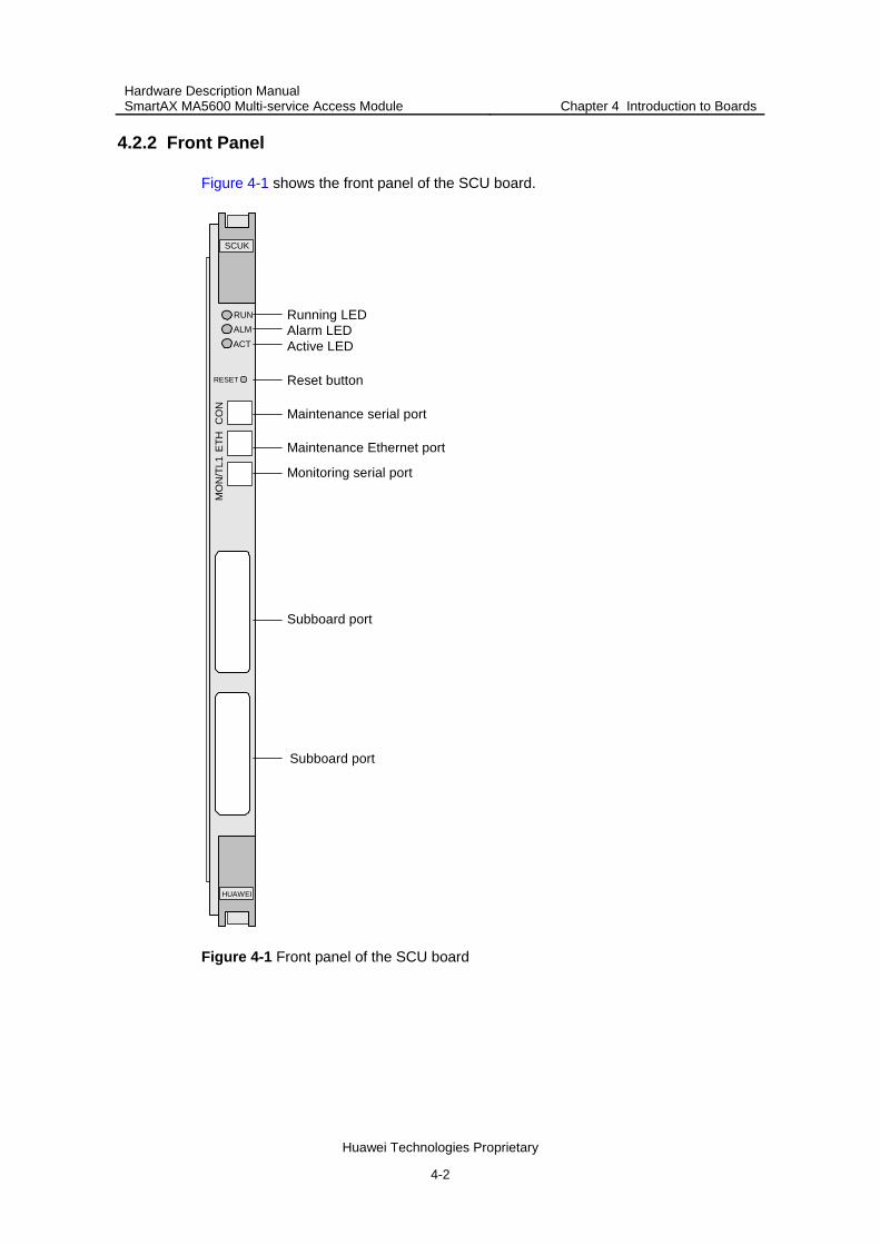
4.2.2 Front Panel
Figure 4-1 shows the front panel of the SCU board.
Running LED
Active LED
Reset button
Subboard port
Alarm LED
Maintenance serial port
Maintenance Ethernet port
Monitoring serial port
Subboard port
HUAWEI
SCUK
RUNALMACT
RESET
ETH
CO
NM
ON
/TL1
Figure 4-1 Front panel of the SCU board
Hardware Description Manual SmartAX MA5600 Multi-service Access Module Chapter 4 Introduction to Boards
Huawei Technologies Proprietary
4-3
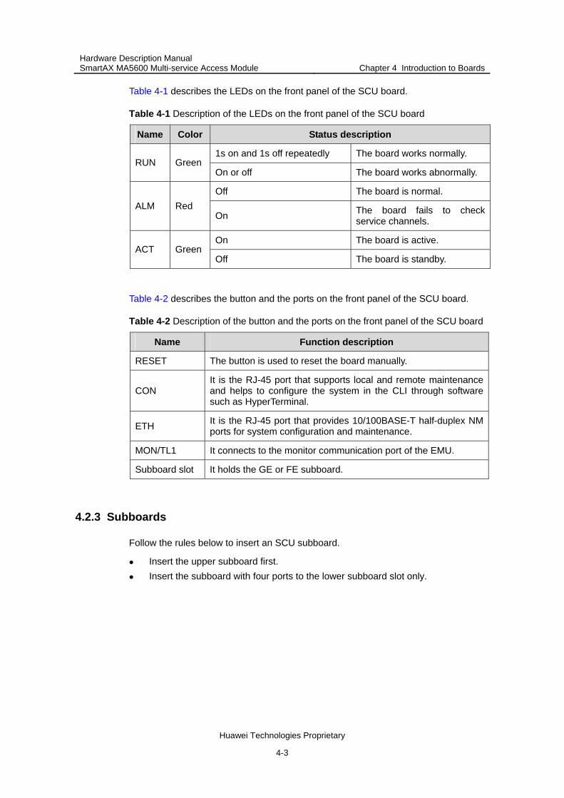
Table 4-1 describes the LEDs on the front panel of the SCU board.
Table 4-1 Description of the LEDs on the front panel of the SCU board
Name Color Status description
1s on and 1s off repeatedly The board works normally. RUN Green
On or off The board works abnormally.
Off The board is normal. ALM Red
On The board fails to check service channels.
On The board is active. ACT Green
Off The board is standby.
Table 4-2 describes the button and the ports on the front panel of the SCU board.
Table 4-2 Description of the button and the ports on the front panel of the SCU board
Name Function description
RESET The button is used to reset the board manually.
CON It is the RJ-45 port that supports local and remote maintenance and helps to configure the system in the CLI through software such as HyperTerminal.
ETH It is the RJ-45 port that provides 10/100BASE-T half-duplex NM ports for system configuration and maintenance.
MON/TL1 It connects to the monitor communication port of the EMU.
Subboard slot It holds the GE or FE subboard.
4.2.3 Subboards
Follow the rules below to insert an SCU subboard.
Insert the upper subboard first. Insert the subboard with four ports to the lower subboard slot only.

Hardware Description Manual SmartAX MA5600 Multi-service Access Module Chapter 4 Introduction to Boards
Huawei Technologies Proprietary
4-4
Table 4-3 describes the subboards that can work with the SCU board.
Table 4-3 Description of subboards attached to the SCU board
Name Port Port parameter
Four multi-mode GE optical ports Central wavelength: 850 nm Transmission distance: 0.5 km Port type: LC
O4GS
Four single-mode GE optical ports Central wavelength: 1,310 nm Transmission distance: 10 km Port type: LC
Two multi-mode GE optical ports Central wavelength: 850 nm Transmission distance: 0.5 km Port type: LC
Two single-mode GE optical ports Central wavelength: 1,310 nm Transmission distance: 10 km Port type: LC
One single-mode and one multi-mode GE optical ports
Single-mode central wavelength: 1,310 nm
Single-mode port transmission distance: 10 km
Multi-mode central wavelength: 850 nm
Multi-mode transmission distance: 0.5 km
Port type: LC
One multi-mode GE optical port Central wavelength: 850 nm Transmission distance: 0.5 km Port type: LC
O2GS
One single-mode GE optical port Central wavelength: 1,310 nm Transmission distance: 10 km Port type: LC
Four multi-mode FE optical ports Central wavelength: 1,310 nm Transmission distance: 2 km Port type: LC
O4FM
Four single-mode FE optical ports Central wavelength: 1,310 nm Transmission distance: 15 km Port type: LC
Two multi-mode FE optical ports Central wavelength: 1,310 nm Transmission distance: 2 km Port type: LC
Two single-mode FE optical ports Central wavelength: 1,310 nm Transmission distance: 15 km Port type: LC
O2FM
One multi-mode FE optical port Central wavelength: 1,310 nm Transmission distance: 2 km Port type: LC

Hardware Description Manual SmartAX MA5600 Multi-service Access Module Chapter 4 Introduction to Boards
Huawei Technologies Proprietary
4-5
Name Port Port parameter
One single-mode FE optical port
Central wavelength: 1,310 nm Transmission distance: 15 km Port type: LC
E4GFA Four GE/FE electrical ports NA
E2GA Two GE/FE electrical ports NA
M2GA Processing the MPLS services and occupying the upper subboard port of the SCU board
4.3 Intelligence Service Unit—ISU
4.3.1 Overview
The ISU board is the intelligence service unit. It serves as a broadband remote access server (BRAS), which performs authentication, authorization and accounting (AAA) on subscribers.
The ISU board provides two GE optical ports and eight FE electrical ports.
The ISU board is of two types: ISUA and ISUE. The difference between them is that the lower subboard port of the ISUA board can hold only the FE optical subboard, while the lower subboard port of the ISUE board can hold only the 4-port FE electrical subboard.
The ISU board resides in slots 14 and 15 of the MA5600 service frame. One service frame can hold up to two ISU boards working in the active/standby mode.
4.3.2 Front Panel
The ISUA and ISUE boards share the same front panel, except that the silkscreens of the board names are different.

Hardware Description Manual SmartAX MA5600 Multi-service Access Module Chapter 4 Introduction to Boards
Huawei Technologies Proprietary
4-6
Figure 4-2 shows the front panel of the ISUA board.
Running LED
Reset button
Subboard port
Alarm LED
Subboard port
Maintenance serial port
Maintenance Ethernet port
HUAWEI
ISUA
RUNALM
RESET
ETH
CO
N
Figure 4-2 Front panel of the ISU board
Table 4-4 describes the LEDs on the front panel of the ISU board.

Hardware Description Manual SmartAX MA5600 Multi-service Access Module Chapter 4 Introduction to Boards
Huawei Technologies Proprietary
4-7
Table 4-4 Description of the LEDs on the front panel of the ISU board
Name Color Status description
1s on and 1s off repeatedly The board works normally. RUN Green
On or off The board works abnormally.
Off The board is normal.
ALM Red On
Service channel check between the ISU and the SCU has failed.
Table 4-5 describes the button and the ports on the front panel of the ISU board.
Table 4-5 Description of the button and the ports on the front panel of the ISU board
Name Function description
RESET The button used to reset the board manually.
CON It is the RJ-45 port that supports local and remote maintenance and helps to configure the system in the CLI through software such as HyperTerminal.
ETH It is the RJ-45 port that provides 10/100BASE-T half-duplex NM ports for system configuration and maintenance.
Subboard port It holds the GE or FE subboard.
4.3.3 Subboards
The ISU board provides the upper and lower subboard slots, where,
For the ISUA board, the upper slot can hold the FE or GE optical subboard, while the lower slot can hold only the FE optical subboard.
For the ISUE board, the upper slot can hold the FE or GE optical subboard, while the lower slot can hold only the 4-FE-electrical-port subboard.
Table 4-6 describes the subboards that can work with the ISU board.
Table 4-6 Description of subboards attached to the ISU board
Name Port Port parameter Subboard position
E4FB Four FE electrical ports NA ISUE lower subboard
slot
O4FBBFour FE multi-mode optical ports
Central wavelength: 1,310 nm
Transmission distance: 2 km
Port type: LC
ISUA upper subboard slot
ISUA lower subboard slot
ISUE upper subboard slot

Hardware Description Manual SmartAX MA5600 Multi-service Access Module Chapter 4 Introduction to Boards
Huawei Technologies Proprietary
4-8
Name Port Port parameter Subboard position
O4FBF For FE single-mode optical ports
Central wavelength: 1,310 nm
Transmission distance: 15 km
Port type: LC
ISUA upper subboard slot
ISUA lower subboard slot
ISUE upper subboard slot
O2GAATwo GE multi-mode optical ports
Central wavelength: 850 nm
Transmission distance: 500 m
Port type: LC
ISUA upper subboard slot
ISUE upper subboard slot
O2GAETwo GE single-mode optical ports
Central wavelength: 1,310 nm
Transmission distance: 10 km
Port type: LC
ISUA upper subboard slot
ISUE upper subboard slot
One GE multi-mode optical port
Central wavelength: 850 nm
Transmission distance: 500 m
Port type: LC O2GAX
One GE single-mode optical port
Central wavelength: 1310 nm
Transmission distance: 10 km
Port type: LC
ISUA upper subboard slot
ISUE upper subboard slot
O1GAAOne GE multi-mode optical port
Central wavelength: 850 nm
Transmission distance: 500 m
Port type: LC
ISUA upper subboard slot
ISUE upper subboard slot
O1GAEOne GE single-mode optical port
Central wavelength: 1,310 nm
Transmission distance: 10 km
Port type: LC
ISUA upper subboard slot
ISUE upper subboard slot
4.4 64-Port ADSL2+ Service Board—ADEF/ADBF
4.4.1 Overview
The ADEF or ADBF board is the 64-port ADSL2+ service board, which provides 64 ADSL2+ subscriber ports.
The difference between the ADEF and ADBF boards is as follows:
The ADEF board supports the ADSL2+ over POTS, and works with the SPLF or SPLL board.

Hardware Description Manual SmartAX MA5600 Multi-service Access Module Chapter 4 Introduction to Boards
Huawei Technologies Proprietary
4-9
The ADBF board supports the ADSL2+ over ISDN, and works with the SPLH board.
The ADEF or ADBF board resides in slots 0–6 and 9–15 of the MA5600 service frame.
4.4.2 Front Panel
The ADEF and ADBF boards have the same front panel, except that the silkscreens of the board names are different.

Hardware Description Manual SmartAX MA5600 Multi-service Access Module Chapter 4 Introduction to Boards
Huawei Technologies Proprietary
4-10
Figure 4-3 shows the front panel of the ADEF board.
Running LEDAlarm LED
xDSL port
xDSL port
HUAWEI
ADEF
RUNALM
xDSL
0xD
SL1
Figure 4-3 Front panel of the ADEF board
Table 4-7 describes the LEDs on the front panel of the ADEF and ADBF boards.

Hardware Description Manual SmartAX MA5600 Multi-service Access Module Chapter 4 Introduction to Boards
Huawei Technologies Proprietary
4-11
Table 4-7 Description of the LEDs on the front panel of the ADEF and ADBF board
Name Color Status description
1s on and 1s off repeatedly The board works normally. RUN Green
On or off The board works abnormally.
Off The board is normal. ALM Red
On The board is faulty.
Table 4-8 describes the ports on the front panel of the ADEF and ADBF board.
Table 4-8 Description of the ports on the front panel of the ADEF and ADBF board
Name Function description
xDSL0 The first 32 xDSL service ports.
xDSL1 The last 32 xDSL service ports.
4.5 32-Port SHDSL Service Board—SHEA
4.5.1 Overview
The SHEA board is the 32-port SHDSL service board. It provides ATM-based SHDSL access services and supports the line protection function.
The SHEA board resides in slots 0–6 and 9–15 of the MA5600 service frame.

Hardware Description Manual SmartAX MA5600 Multi-service Access Module Chapter 4 Introduction to Boards
Huawei Technologies Proprietary
4-12
4.5.2 Front Panel
Figure 4-4 shows the front panel of the SHEA board.
Running LEDAlarm LED
SHDSL port
HUAWEI
SHEA
RUNALM
SH
DS
L
Figure 4-4 Front panel of the SHEA board

Hardware Description Manual SmartAX MA5600 Multi-service Access Module Chapter 4 Introduction to Boards
Huawei Technologies Proprietary
4-13
Table 4-9 describes the LEDs on the front panel of the SHEA board.
Table 4-9 Description of the LEDs on the front panel of the SHEA board
Name Color Status description
1s on and 1s off repeatedly The board works normally. RUN Green
On or off The board works abnormally.
Off The board is normal. ALM Red
On The board is faulty.
Table 4-10 describes the port on the front panel of the SHEA board.
Table 4-10 Description of the port on the front panel of the SHEA board
Name Function description
SHDSL Provides 32 SHDSL service ports
4.6 ATM Interface Board—AIUG
4.6.1 Overview
The AIUG board is the ATM interface board of the MA5600.
The AIUG board converts ATM cells into IP packets, and then reports them to the main control board through the GE bus of the backplane. The main control board provides the IP upstream services.
The following are the subboards and ports supported by the AIUG board.
155M ATM optical interface subboard: It provides 1–4 155M ATM optical ports. IMA subboard: It provides eight IMA E1 ports. E3 subboard: It provides 1–2 E3 ports.
The AIUG board resides in slots 0–6 and 9–15 of the MA5600 service frame.

Hardware Description Manual SmartAX MA5600 Multi-service Access Module Chapter 4 Introduction to Boards
Huawei Technologies Proprietary
4-14
4.6.2 Front Panel
Figure 4-5 shows the front panel of the AIUG board.
Subboard port
Subboard port
Running LEDAlarm LED
Reset button
HUAWEI
AIUG
RUNALM
RESET
Figure 4-5 Front panel of the AIUG board

Hardware Description Manual SmartAX MA5600 Multi-service Access Module Chapter 4 Introduction to Boards
Huawei Technologies Proprietary
4-15
Table 4-11 describes the LEDs on the front panel of the AIUG board.
Table 4-11 Description of the LEDs on the front panel of the AIUG board
Name Color Status description
1s on and 1s off repeatedly The board works normally. RUN Green
On or off The board works abnormally.
Off The board is normal. ALM Red
On Communication of the board is faulty.
Table 4-12 describes the button and the ports on the front panel of the AIUG board.
Table 4-12 Description of the button and the ports on the front panel of the AIUG board
Name Function description
RESET The button is used to reset the board manually.
Subboard port It holds the 155 M optical subboard.
4.6.3 Subboards
Follow the rules below to insert an AIUG subboard port.
Insert the upper subboard first. Insert the lower subboard to the lower subboard slot only when you have
inserted the upper subboard to the upper subboard slot. The subboard traffic in the upper subboard slot shall be larger than or equal to
that in the lower subboard slot.
Table 4-13 describes the subboard attached to the AIUG board.
Table 4-13 Description of the subboard attached to the AIUG board
Name Port Port parameter
O1CTG One 155 M single-mode optical port
Central wavelength: 1,310 nm Transmission distance: 30 km Port type: SC
O1CTB One 155 M multi-mode optical port Central wavelength: 1,310 nm Transmission distance: 2 km Port type: SC
O2CTG Two 155 M single-mode optical ports
Central wavelength: 1,310 nm Transmission distance: 30 km Port type: SC

Hardware Description Manual SmartAX MA5600 Multi-service Access Module Chapter 4 Introduction to Boards
Huawei Technologies Proprietary
4-16
Name Port Port parameter
O2CTB Two 155 M multi-mode optical ports
Central wavelength: 1,310 nm Transmission distance: 2 km Port type: SC
4.6.4 DIP Switches of Subboard
The E8IT subboard (IMA service subboard) is of two types: E8IT.2 REV.0 and E8IT.2 REV.A.
The E8IT.2 REV.0 subboard supports only the 75-ohm coaxial cable. The E8IT.2 REV.A subboard supports both the 75-ohm coaxial cable and the
120-ohm twisted pair by setting the DIP switches.
Both types of E8IT subboards have five sets of DIP switches (S1–S5), where,
S5 has four bits. S1, S2, S3, and S4 have eight bits each.
The port impedance of the E8IT.2 REV.0 is 75 ohms by default, you need not configure it.
Table 4-14 describes the settings of DIP switches.
Table 4-14 Settings of DIP switches of the E8IT.2 REV.0 subboard
DIP switch 75-ohm
S1 Bits 1–8: ON
S2 Bits 2, 4, 6, 8: OFF Bits 1, 3, 5, 7: ON
S3 Bits 1–8: ON
S4 Bits 2, 4, 6, 8: OFF Bits 1, 3, 5, 7: ON
S5 Bits 1, 2, 3: OFF Bit 4: ON
The port impedance of the E8IT.2 REV.A subboard is 75 ohms by default. You can set the DIP switches according to the cable type.

Hardware Description Manual SmartAX MA5600 Multi-service Access Module Chapter 4 Introduction to Boards
Huawei Technologies Proprietary
4-17
Table 4-15 describes the of DIP switches.
Table 4-15 Settings of DIP switches of the E8IT.2 REV.A subboard
DIP switch 75-ohm 120-ohm
S1 Bits 1–8: ON Bits 1–8: OFF
S2 Bits 2, 4, 6, 8: OFF Bits 1, 3, 5, 7: ON
Bits 1–8: OFF
S3 Bits 1–8: ON Bits 1–8: OFF
S4 Bits 2, 4, 6, 8: OFF Bits 1, 3, 5, 7: ON
Bits 1–8: OFF
S5 Bit 1: OFF Bits 2, 3, 4: ON
Bits 1–4: ON
4.7 Ethernet Interface Board—EIUB
4.7.1 Overview
The EIUB board is the Ethernet interface board. It provides the Ethernet upstream services.
The EIUB board resides in slots 9–15 of the MA5600 service frame.

Hardware Description Manual SmartAX MA5600 Multi-service Access Module Chapter 4 Introduction to Boards
Huawei Technologies Proprietary
4-18
4.7.2 Front Panel
Figure 4-6 shows the front panel of the EIUB board.
Alarm LED
Subboard port
Running LED
HUAWEI
EIUB
RUN
ALM
Figure 4-6 Front panel of the EIUB board

Hardware Description Manual SmartAX MA5600 Multi-service Access Module Chapter 4 Introduction to Boards
Huawei Technologies Proprietary
4-19
Table 4-16 describes the LEDs on the front panel of the EIUB board.
Table 4-16 Description of the LEDs on the front panel of the EIUB board
Name Color Status description
1s on and 1s off repeatedly The board works normally. RUN Green 0.25s on and 0.25s off
repeatedly The board is reset.
Off The board is normal.
ALM Red On
Checks if service channel between the SCU and the EIUB has failed.
Table 4-17 describes the port on the front panel of the EIUB board.
Table 4-17 Description of the port on the front panel of the EIUB board
Name Function description
Subboard port Provides the Ethernet upstream subboard port.
4.7.3 Subboards
Table 4-18 describes the subboards attached to the EIUB board.
Table 4-18 Description of subboards attached to the EIUB board
Name Port Applicable optical module
Multi-mode Central wavelength: 850 nm Transmission distance: 0.5 km Port type: LC
O2GS Two GE optical ports Single-mode Central wavelength: 1,310 nm Transmission distance: 10 km Port type: LC
E2GA Two GE/FE electrical ports NA

Hardware Description Manual SmartAX MA5600 Multi-service Access Module Chapter 4 Introduction to Boards
Huawei Technologies Proprietary
4-20
4.8 64-Port SPL Board—SPLF/SPLH/SPLL
4.8.1 Overview
The SPLF/SPLH/SPLL board is the 64-port SPL board. It separates the POTS signals or ISDN signals from the ADSL2+ signals.
Table 4-19 describes the differences between the SPLF, SPLH, and SPLL.
Table 4-19 Differences between the SPLF, SPLH, and SPLL
Name Applied line Port impedance
SPLF POTS 600 ohms
SPLH ISDN (2B1Q/4B3T) 135 ohms/150 ohms
SPLL POTS Complex impedance
The SPLF/SPLH/SPLL board resides in slots 0–6 and 9–15 of the MA5600 SPL frame.
4.8.2 Front Panel
The SPLF and SPLL boards have the same front panel, except that the silkscreens of the board name are different.

Hardware Description Manual SmartAX MA5600 Multi-service Access Module Chapter 4 Introduction to Boards
Huawei Technologies Proprietary
4-21
Figure 4-7 shows the front panel of the SPLF board.
HUAWEI
SPLF
xDSL
0xD
SL1
xDSL port
xDSL port
PS
TN0
PS
TN1
POTS port
POTS port
LIN
E0
LIN
E1
Subscriber line port
Subscriber line port
Figure 4-7 Front panel of the SPLF board

Hardware Description Manual SmartAX MA5600 Multi-service Access Module Chapter 4 Introduction to Boards
Huawei Technologies Proprietary
4-22
Figure 4-8 shows the front panel of the SPLH board.
HUAWEI
SPLH
xDS
L0xD
SL1
xDSL port
xDSL port
ISD
N0
ISD
N1
ISDN port
ISDN port
LIN
E0LI
NE1
Subscriber l ine port
Subscriber l ine port
Figure 4-8 Front panel of the SPLH board
Table 4-20 describes the ports on the front panel of the SPLF/SPLH/SPLL board.
Table 4-20 Description of the ports on the front panel of the SPLF/SPLH/SPLL board
Name Function description
xDSL0 The first 32 xDSL service ports
xDSL1 The last 32 xDSL service ports

Hardware Description Manual SmartAX MA5600 Multi-service Access Module Chapter 4 Introduction to Boards
Huawei Technologies Proprietary
4-23
Name Function description
LINE0 The first 32 subscriber line service ports
LINE1 The last 32 subscriber line service ports
PSTN0 The first 32 POTS service ports
PSTN1 The last 32 POTS service ports
ISDN0 The first 32 ISDN service ports
ISDN1 The last 32 ISDN service ports