introduction to building maintenance units
TRANSCRIPT

BUILDING MAINTENANCE UNITS (a.k.a. Façade Access Equipment)
Introduction & Planning considerations
Presented by:
Samson Rajan Babu MCIBSE
Façade Access Consultant & Project Manager
Dubai, UAE

Important Note:
This document is released to the public for the purpose
of knowledge sharing only. This document shall not be
used by 3rd parties with commercial interests.
The user of this document is responsible to identify the
latest amendments for any regulations referred herein.
Some of the images included in this document represent the work of other professionals. They are cited in the document for the express purpose of communicating ideas and are not for commercial use. Credit to the appropriate professionals is available upon request.
© Copyright Samson Rajan Babu Thangiah, Tamil Nadu, India

Description: Permanently installed on a specific building or structure for the inspection, cleaning and maintenance of the façades.
Other Names: Façade Access Equipment Window Washing Equipment Permanent Access Suspended Platform Cleaning cradle system
Other possible use: Glass panel replacement

TYPES OF BMU:
• Manual (removable & relocatable) Roof Systems
• External Monorail Systems – Manual & Motorised
• Motorised Roof systems
• Specially designed BMUs.

Davit systems
Counterweighted Beams
Internal Monorail
Parapet Clamps
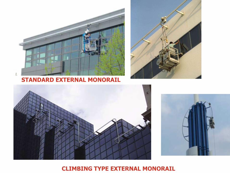
STANDARD EXTERNAL MONORAIL
CLIMBING TYPE EXTERNAL MONORAIL

ROOF MOUNTED MOTORISED MACHINES

SPECIALLY DESIGNED ACCESS SYSTEMS

SPECIALLY DESIGNED ACCESS SYSTEMS
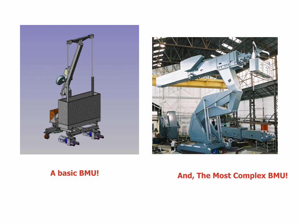
And, The Most Complex BMU! A basic BMU!

MANUFACTURERS (International with Worldwide projects):
• SECALT – LUXEMBOURG
• MANNTECH – GERMANY
• COX GOMYL – AUSTRALIA, SPAIN
• FARRA ENGINEERING – NEW ZEALAND
• FAÇADE HOISTS – UK
• SKYGONDOLA – SPAIN
• AESA – SPAIN
• GEDA - GERMANY
Governing Codes: BSEN 1808, AS 1418 BS 6037
CSI Specification Division: 11 - Equipment

ESSENTIALS OF A BMU MANUFACTURER:
• Compliance to governing codes
• CE Certified Prototype Designs, Lifting and Safety components
• Years of experience, Design versatility & Capability
• Qualified structural design engineers & local certification
of design calculations.
• Type tested & proven components from reputed sub-contractors
• High-tech fabrication facility
• Special consideration for surface treatment and protection
• QA/QC procedures
• Trained installers
• Spare parts availability

While designing BMU systems:
Reduce the level of risk in the final design to “As Low As Reasonably Practicable” (A.L.A.R.P)
Façade Design should allow for a BMU design that is:
• Installed safely
• Accessed safely
• Used, inspected and maintained safely
Problem façades include:
• Stepped façades, Ribbed façades
• Curved elevations – Concave/Convex
• Localised steps in the façade, eg. sun shading, ledges, canopies, fins
Projecting balcony / Mashrabiya
• Sloped façade (inwards/outwards)
• Local attachments to the façade, which protrude: CCTV cameras,
signage
• Recessed windows.
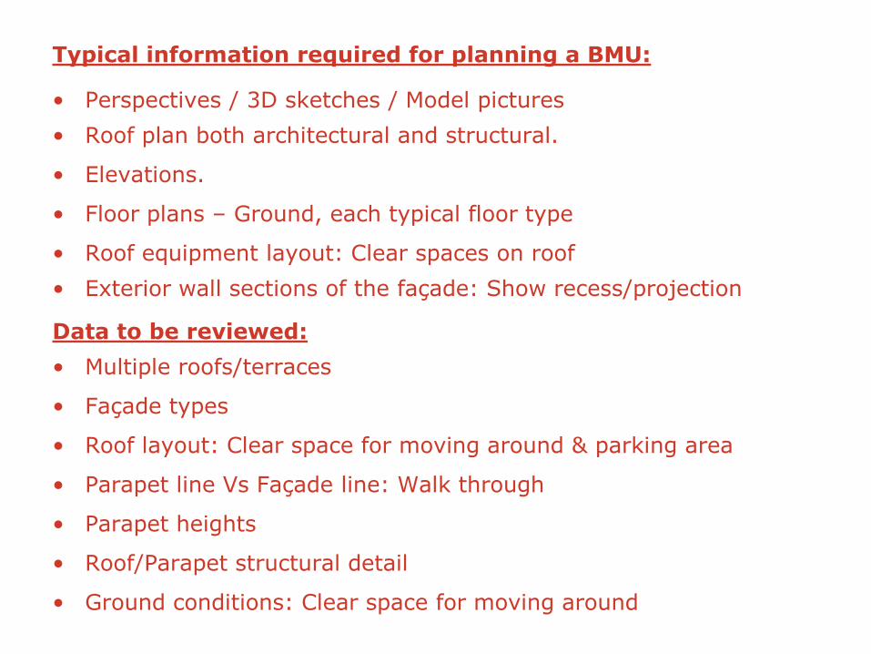
Typical information required for planning a BMU:
• Perspectives / 3D sketches / Model pictures
• Roof plan both architectural and structural.
• Elevations.
• Floor plans – Ground, each typical floor type
• Roof equipment layout: Clear spaces on roof
• Exterior wall sections of the façade: Show recess/projection
Data to be reviewed:
• Multiple roofs/terraces
• Façade types
• Roof layout: Clear space for moving around & parking area
• Parapet line Vs Façade line: Walk through
• Parapet heights
• Roof/Parapet structural detail
• Ground conditions: Clear space for moving around

Solution depends on:
• Combination of Roof / Parapet / Ground conditions
• Budget
• Frequency of cleaning (cleaning cycle analysis)
• Aesthetics: While working & when parked
• Parking requirements
• Availability of structural support for the solution
Solutions can be:
• Single/multiple manual systems with common/dedicated platforms.
• Single/multiple monorail systems with common/dedicated
platforms.
• Single/multiple roof trolleys with common/dedicated platforms.

FAÇADE TYPES
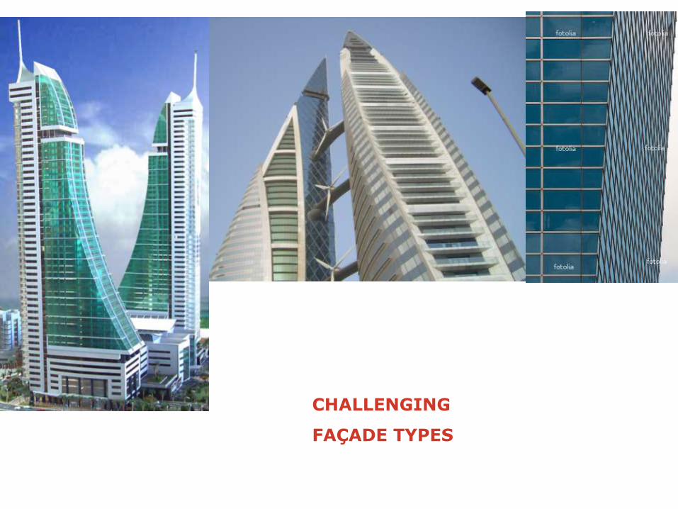
CHALLENGING
FAÇADE TYPES

Various roof conditions
Sloped roof
Mashrabiya
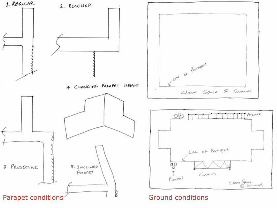
Parapet conditions Ground conditions

Cradle Drop Layout &
Cleaning cycle analysis
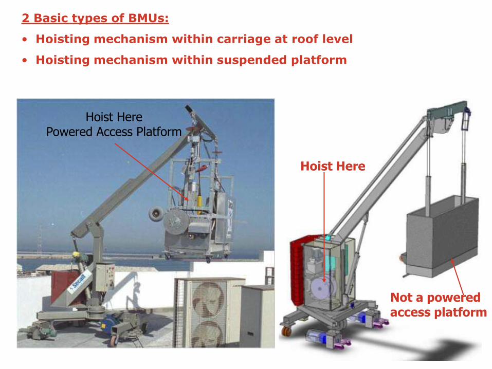
2 Basic types of BMUs:
• Hoisting mechanism within carriage at roof level
• Hoisting mechanism within suspended platform
Hoist Here Powered Access Platform
Hoist Here
Not a powered access platform

Motorised platform:
• Heavy – difficult to handle
• Platform space not roomy.
• Cleaner must check proper
operation of various devices
• Use if lifting below 40mtrs.
• Can be shared with other roof
systems.
Non-motorised platform:
• Light weight – easy to handle
• Platform is spacious
• Cleaner can concentrate in cleaning
• Use if lifting more than 40mtrs.
• Cannot be shared – used only on roof trolleys
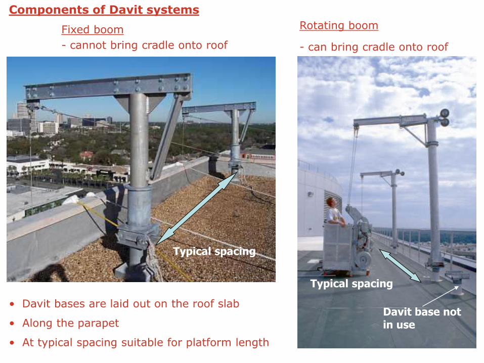
Typical spacing
Typical spacing
Davit base not in use
• Davit bases are laid out on the roof slab
• Along the parapet
• At typical spacing suitable for platform length
Components of Davit systems
Fixed boom
- cannot bring cradle onto roof
Rotating boom
- can bring cradle onto roof
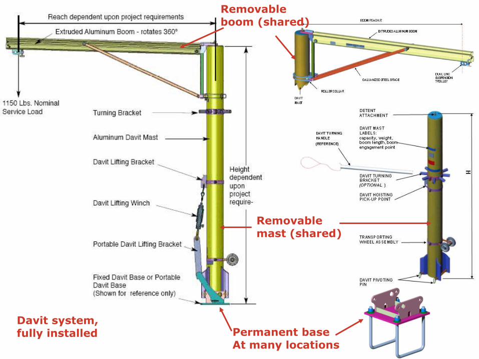
Permanent base At many locations
Removable mast (shared)
Davit system, fully installed
Removable boom (shared)

Through bolt fixing Cast-in U bolt fixing

REQUIREMENTS OF BMU SYSTEMS:
Manual systems: (Davits, Roof anchors, Roof beams, Clamps)
• Floor mount (or) parapet mount
• Structurally sound roof slab & parapets (RCC or steel) – Verify loads!
• RCC pedestals – Verify height & waterproofing
• Advisable to use through-bolting or cast-in bolts inside concrete. (Drill in place or chemical bolts not recommended due to high pullout loads.)
• When relocating, the suspended load must be removed (need landing space directly below suspension point.) Keep ground floor clear!
• Usually in natural aluminium or galvanised steel finish
Disadvantages:
• Heavy, laborious & time-consuming to use.
• Platform stays at ground floor most of the time.
• Hooking & unhooking of ropes need extra care.
• Important components/fasteners are lost & replaced with local means.

Components of Monorail:
Monorail Track
Support bracket
Traversing trolley -Manual pull -Rope driven -Motorised
• Monorail brackets are anchored on parapet wall (straight brackets) or on floor slab (L-shape brackets)
• At typical spacing of 2000mm
• Typical overhang is 700mm for smooth façade types.
700mm
L shape bracket
Straight bracket

REQUIREMENTS OF BMU SYSTEMS:
Monorail systems:
• Floor mount (or) parapet mount
• Structurally sound roof slab & parapets (RCC or steel) – Verify loads!
• RCC pedestals – Verify height & waterproofing
• Advisable to use through-bolting or cast-in bolts inside concrete. (Drill in place or chemical bolts not recommended due to high pullout loads.)
• When sharing cradle with another monorail, need landing space directly below suspension point. Keep ground floor clear at the point of cradle transfer.
• Park at the rear of building (with ropes hanging) Not recommended.
• Provide access door at monorail level to remove ropes for clean storage &
sharing cradle.
• In variety of finishes: natural aluminium, anodized, powdercoated to RAL color
Disadvantages:
• Cradle sharing is laborious & time-consuming.
• Platform stays at ground floor most of the time.
• Hooking & unhooking of ropes need extra care & access doors.

Types of roof trolleys:
* With motorised platform * With non-motorised platform
Design variations:
• Trolleys running on RCC runway / Steel plate runway (with tiller)
• Trolleys running on RCC runway / Steel plate runway with continuous
guide angle track.
• Trolleys running on Steel beam tracks on floor slab
• Trolleys running on Steel beam tracks on parapet wall
• Pedestal type (do not run around the roof.)
• Trolleys climbing on a sloped roof / parapet

Standard machine on I beam tracks
Climbing slopes-Self powered
Machine with rail tracks on parapet wall Climbing slopes-
Remote powered
Standard machine on RCC runway
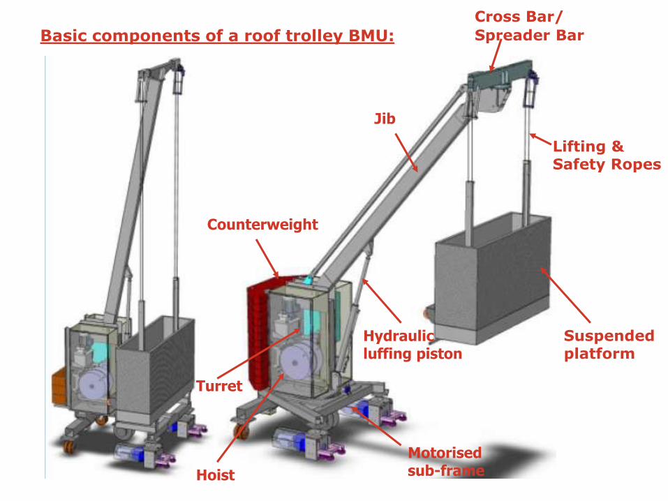
Basic components of a roof trolley BMU:
Suspended platform
Cross Bar/
Spreader Bar
Jib
Motorised sub-frame
Turret
Counterweight
Hoist
Hydraulic luffing piston
Lifting & Safety Ropes

MOVEMENTS OF A BMU CW/CCW Cross bar slewing
Up/Down Jib Luffing
CW/CCW Turret slewing
Left/Right Traversing
Up/Down Hoisting
Cradle Forward luffing

Traversing
Spreader bar
slewing Slewing
Luffing
Horizontal elbow
Movements of BMU components

Mast rise/lower
Jib telescoping
Vertical elbow
Movements of BMU components

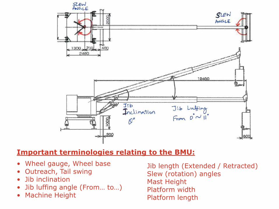
• Wheel gauge, Wheel base • Outreach, Tail swing • Jib inclination • Jib luffing angle (From… to…) • Machine Height
Jib length (Extended / Retracted) Slew (rotation) angles Mast Height Platform width Platform length
Important terminologies relating to the BMU:
REQUIREMENTS OF BMU SYSTEMS:
Roof trolley systems:
• Structurally sound roof slab & parapets (RCC or steel) – Verify wheel loads!
• RCC pedestals – Verify height & waterproofing
• Dead weight of machine
• Parked at the rear of building or at designated parking garage on roof.
• Can be hidden inside the building when façade doors are provided for
moving out.
• In variety of finishes: Galvanised steel / powder coated to RAL color
• Safest solution to access complicated façades
Disadvantages:
• Expensive
• Requires considerable amount of free space at roof for movement.
• Heavy & puts considerable load on structure.

MEP REQUIREMENTS OF BMU SYSTEMS:
• 3-Phase, Neutral, Earth – 5 pin AC power supply
• Sockets at many locations on roof level for roof trolleys – spaced @15mtrs.
• Sockets at many locations on ground level for monorail / manual systems – spaced @15mtrs.
• Usually 32Amps. Weatherproof sockets on the building (socket type to match with plug on BMU.)
• Provide 1 No. 1-Phase, Neutral, Earth – 3 pin AC power supply for use of maintenance tools.
• Usually 16Amps. Weatherproof sockets on the building. (Most common type in the local market.)
• Provide water supply mains – for cleaners to carry water inside the cradle. Provide at platform storage level.
Weatherproof
Power socket

Track systems for Roof Trolley BMU
• To spread machine load evenly on the supporting structure.
• Provide means to climb over sloped roofs
• To facilitate parking
• To change movement direction without turning radius
• To hide machine from general view
RCC Plinths
Baseplate
with isolation Cast-in bolt tied with
reinforcement
RCC runway
‘L’ angle guiding track

‘L’ angle guiding track
I beam tracks on elevated steel structure
Gear rack track for climbing slopes
RCC runway with guiding rail
I beam tracks on sloped roof
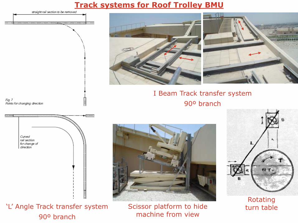
Track systems for Roof Trolley BMU
I Beam Track transfer system
90º branch
Scissor platform to hide machine from view
Rotating turn table ‘L’ Angle Track transfer system
90º branch

BMU: Platform stabilisation
• Applicable when lifting height is more than 40mtrs.
• Rope with cradle is tied to façade at 20mtr. on elevation – to prevent cradle swaying with wind
• Horizontal spacing depends on cradle width (W+300mm)
• Restraint sockets built into façade – flush mount or projecting bracket type.
• Lashing on structural fins
• Min. 100kgs. Pull out load on façade at any direction (for standard equipment)

BMU: Platform stabilisation
• Coordination required with façade supplier – At early stage
• To finalise locations of sockets on façade, quantity required, dimensions and fixing details
• 2 components:
1) Restraint socket (built-inside façade) – usually at mullion joints
2) Restraint plug with lanyard (on the cradle)
• Ask for Restraint layout drawing (per elevation), Restraint details drawing – From BMU supplier.
• BMU supplier supplies the sockets & Façade supplier installs them on his façade.
• Sockets quantity: Large depending on area of façade
• Lanyards quantity: (1 on left, 1 on right) X Elevation levels
Flush mount Detent-pin
Projecting bracket

Built-in restraint socket
Restraint plug with lanyard
Continuous mullion guides
• Sockets on façade preferred.
• Sockets on structure (behind façade) not recommended – trouble with dimensions.
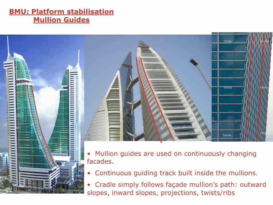
• Mullion guides are used on continuously changing facades.
• Continuous guiding track built inside the mullions.
• Cradle simply follows façade mullion’s path: outward
slopes, inward slopes, projections, twists/ribs
BMU: Platform stabilisation Mullion Guides

BMU: Special Accessories: FORWARD LUFF/PANTOGRAPH
Cradle Forward Luff Distance
Centre of rope Centre of cradle
• Access recessed façades
• Pantograph mechanism
• Manual or motorised
• Standard designs up to 2.5mtrs.
• Special designs up to 5.5mtrs.
• Suspended load is 3-5 times more!
• Roof machine becomes very heavy!

BMU: Special Accessories: Single suspension platforms
Bosun chair (Flying seat) 1-Man cradle
• Advantageous with less suspended load. • Easy to handle & carry around • Use only for lowrise applications (up to 40mtrs.)
• Single suspension at centre: Tendency to swivel
• Less stable
• Manual / Motorised versions

BMU on world’s tallest building – BURJ KHALIFA, DUBAI
Upper levels:
• Roof trolleys on roof slab
• Telescopic jib with elbow end
Cross bar Telescoping Jib

BMU on world’s tallest building – BURJ KHALIFA, DUBAI
Lower levels:
• Roof trolleys running on wall mounted rail tracks: Externally to façade.
• Roof trolley with cradle is parked inside the building façade when not in use. A façade door hides roof trolley from view.
Cross bar
External rail track
Parking garage
Door on façade
Roof trolley with cradle in working position

Some of the images included in this document represent the work of other professionals. They are cited in the document for the express purpose of communicating ideas and are not for commercial use. Credit to the appropriate professionals is available upon request.
© Copyright Samson Rajan Babu Thangiah, Tamil Nadu, India