introduction to cnc - islamic university of...
TRANSCRIPT

INTRODUCTION TO INTRODUCTION TO CNCCNC

HISTORYHISTORYUS Air Force commissioned MIT to develop the US Air Force commissioned MIT to develop the first "numerically controlled" machine in 1949. It first "numerically controlled" machine in 1949. It was demonstrated in 1952. was demonstrated in 1952. At 1970At 1970--1972 1972 firstfirst ComputerComputer NumericNumeric ControlControl
machinesmachines werewere developeddeveloped..Today, computer numerical control (CNC) Today, computer numerical control (CNC) machines are found almost everywhere, from machines are found almost everywhere, from small job shops in rural communities to small job shops in rural communities to companies in large urban areas. companies in large urban areas.
DEFINITIONDEFINITION
InIn CNC CNC ((Computer Numerical ControlComputer Numerical Control),), the the instructions are stored as a program in a instructions are stored as a program in a micromicro--computer attached to the machine. computer attached to the machine. The computer will also handle much of the The computer will also handle much of the control logic of the machine, making it control logic of the machine, making it more adaptable than earlier hardmore adaptable than earlier hard--wired wired controllers.controllers.
CNC APPLICATIONSCNC APPLICATIONS
MachiningMachining2.5D / 3D 2.5D / 3D Turning ~ Lathes, Turning Centre Turning ~ Lathes, Turning Centre Milling ~ Machining Centers Milling ~ Machining Centers FormingForming2D 2D Plasma and Laser Cutting Plasma and Laser Cutting Blanking, nibbling and punching Blanking, nibbling and punching 3D 3D Rapid Prototyping Rapid Prototyping

SAMPLESAMPLECNC MACHINESCNC MACHINES

CNC TURNINGCNC TURNING
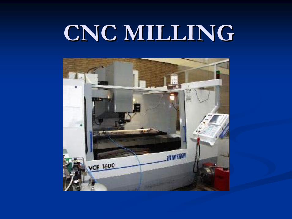
CNC MILLINGCNC MILLING
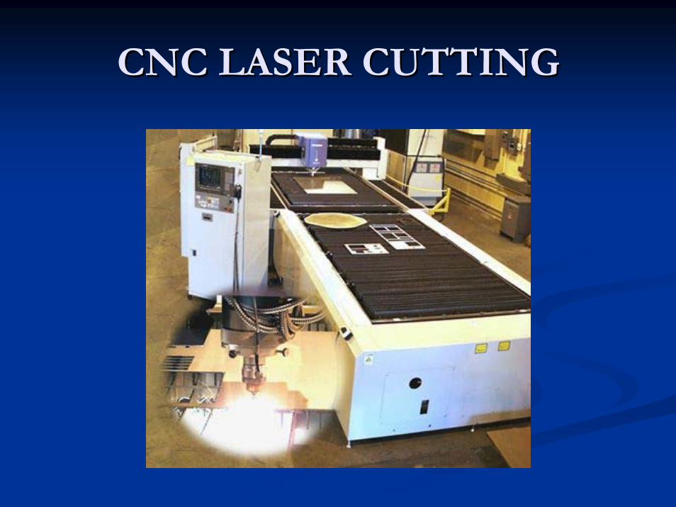
CNC LASER CUTTINGCNC LASER CUTTING

CNC PLASMA CUTTINGCNC PLASMA CUTTING

CNC PRESSCNC PRESS
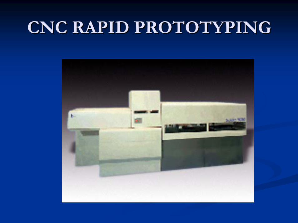
CNC RAPID PROTOTYPINGCNC RAPID PROTOTYPING
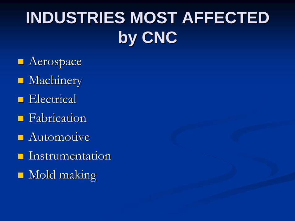
INDUSTRIES MOST AFFECTED INDUSTRIES MOST AFFECTED byby CNCCNC
Aerospace Aerospace Machinery Machinery Electrical Electrical Fabrication Fabrication Automotive Automotive Instrumentation Instrumentation Mold making Mold making

SAMPLE PRODUCTSSAMPLE PRODUCTSOF OF
CNC MANUFACTURINGCNC MANUFACTURING

AUTOMOTIVE INDUSTRYAUTOMOTIVE INDUSTRYEngineEngine BlockBlock
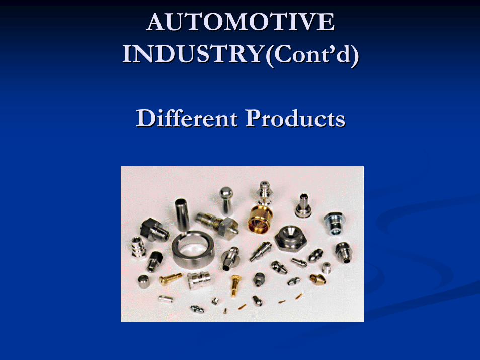
AUTOMOTIVE AUTOMOTIVE INDUSTRY(INDUSTRY(ContCont’’dd))
DifferentDifferent ProductsProducts
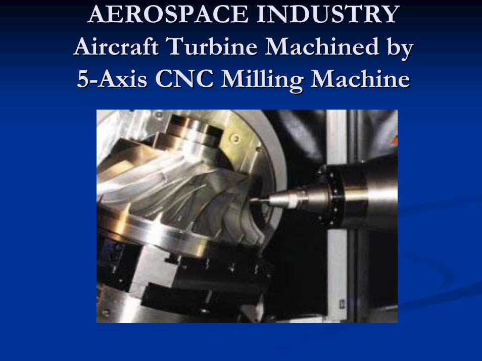
AEROSPACE INDUSTRYAEROSPACE INDUSTRYAircraftAircraft TurbineTurbine MachinedMachined by by 55--AxisAxis CNC CNC MillingMilling MachineMachine
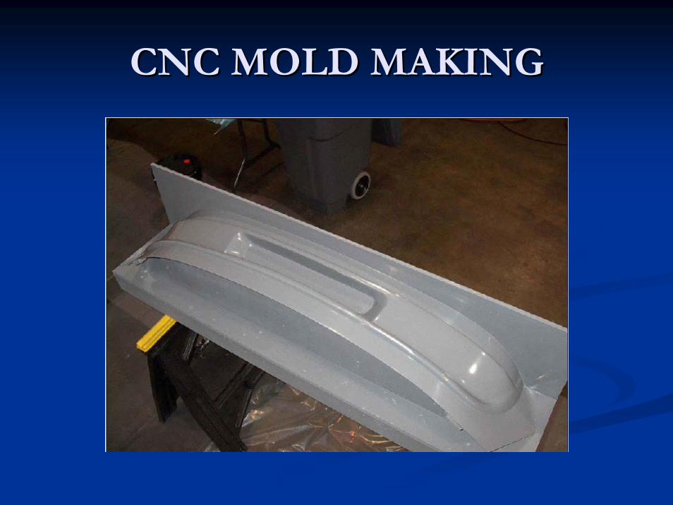
CNC MOLD MAKINGCNC MOLD MAKING
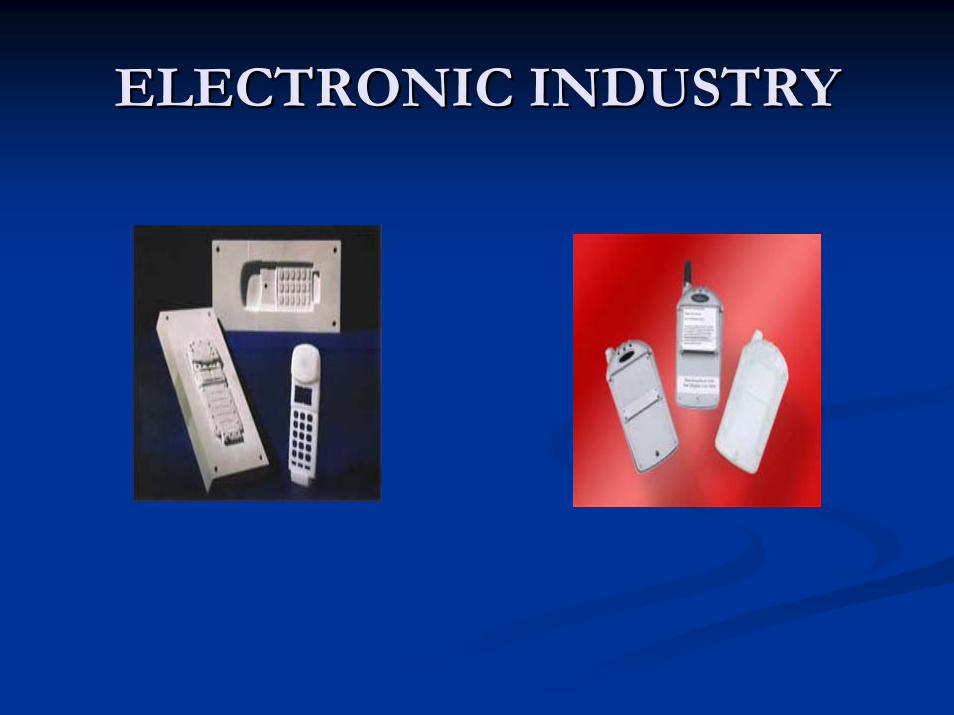
ELECTRONIC INDUSTRYELECTRONIC INDUSTRY

RAPID PROTOTYPING RAPID PROTOTYPING PRODUCTSPRODUCTS
ADVANTAGES of CNCADVANTAGES of CNC
ProductivityProductivity
Machine utilization is increased because more Machine utilization is increased because more time is spent cutting and less time is taken by time is spent cutting and less time is taken by positioning. positioning. Reduced setup time increases utilization too. Reduced setup time increases utilization too.
ADVANTAGES of ADVANTAGES of CNCCNC
QualityQuality
Parts are more accurate. Parts are more accurate. Parts are more repeatable. Parts are more repeatable. Less waste due to scrap. Less waste due to scrap.

ADVANTAGES of ADVANTAGES of CNCCNC
Reduced inventoryReduced inventory
Reduced setup time permits smaller economic Reduced setup time permits smaller economic batch quantities. batch quantities. Lower lead time allows lower stock levels. Lower lead time allows lower stock levels. Lower stock levels reduce interest charges and Lower stock levels reduce interest charges and working capital requirements. working capital requirements.

ADVANTAGES of ADVANTAGES of CNCCNC
Machining Complex shapesMachining Complex shapes
Slide movements under computer control. Slide movements under computer control. Computer controller can calculate steps. Computer controller can calculate steps. First NC machine built 1951 at MIT for aircraft First NC machine built 1951 at MIT for aircraft skin milling. skin milling.

ADVANTAGES of ADVANTAGES of CNCCNC
Management ControlManagement Control
CNC leads to CAD CNC leads to CAD Process planning Process planning Production planning Production planning
DRAWBACKS of CNCDRAWBACKS of CNCHigh capital cost High capital cost Machine tools cost $30,000 Machine tools cost $30,000 -- $1,500,000 $1,500,000 Retraining and recruitment of staff Retraining and recruitment of staff New support facilities New support facilities High maintenance requirementsHigh maintenance requirementsNot costNot cost--effective for loweffective for low--level production on simple level production on simple partspartsAs geometric complexity or volume increases CNC As geometric complexity or volume increases CNC becomes more economicalbecomes more economicalMaintenance personnel must have both mechanical and Maintenance personnel must have both mechanical and electronics expertise electronics expertise
CNC SYSTEM CNC SYSTEM ELEMENTSELEMENTS
CNC SYSTEM ELEMENTSCNC SYSTEM ELEMENTS
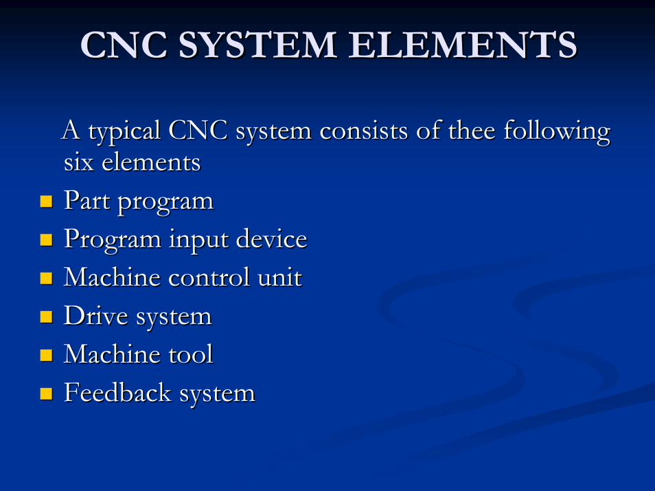
A typical CNC system consists of theA typical CNC system consists of theee following following six elements six elements Part program Part program Program input device Program input device Machine control unit Machine control unit Drive system Drive system Machine tool Machine tool Feedback system Feedback system
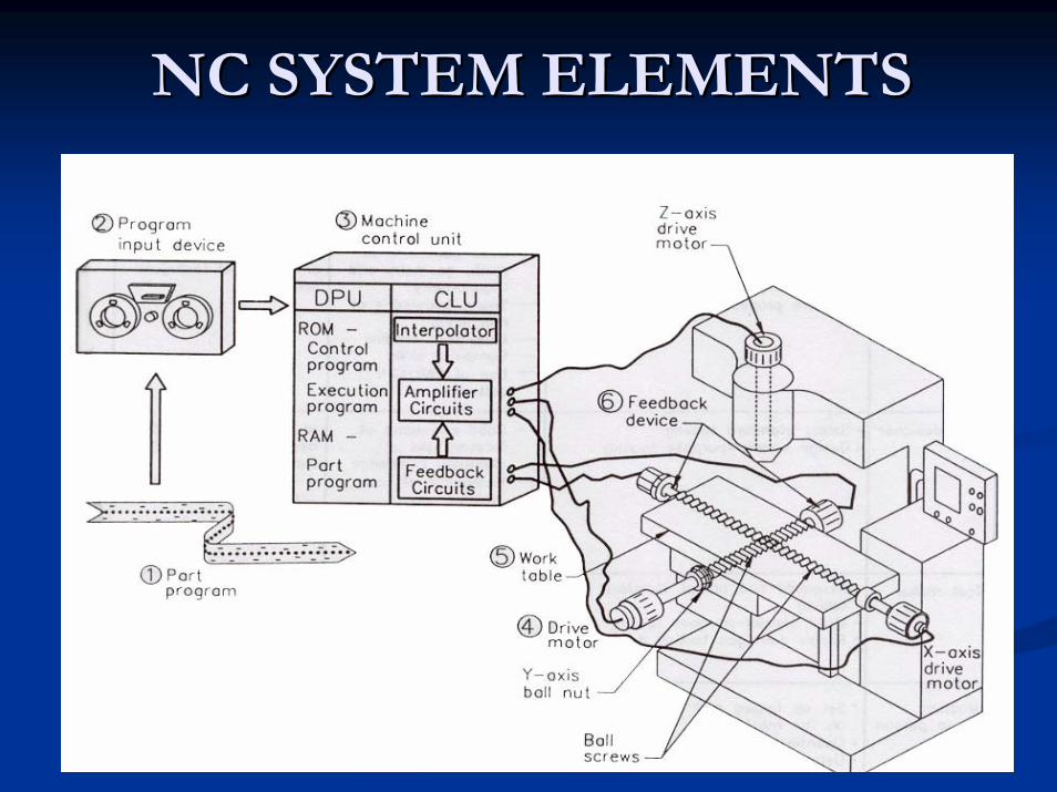
NCNC SYSTEM ELEMENTSSYSTEM ELEMENTS
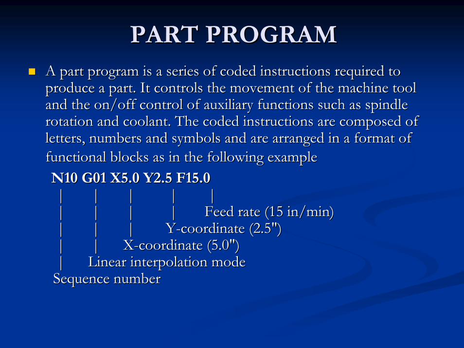
PART PROGRAMPART PROGRAMA part program is a series of coded instructions required to A part program is a series of coded instructions required to produce a part. It controls the movement of the machine tool produce a part. It controls the movement of the machine tool and the on/off control of auxiliary functions such as spindle and the on/off control of auxiliary functions such as spindle rotation and coolant. The coded instructions are composed of rotation and coolant. The coded instructions are composed of letters, numbers and symbols and are arranged in a format of letters, numbers and symbols and are arranged in a format of functional blocks as in the following examplefunctional blocks as in the following exampleN10 G01 X5.0 Y2.5 F15.0N10 G01 X5.0 Y2.5 F15.0|| || || || | | || || || || Feed rate (15 in/min) Feed rate (15 in/min) || || || YY--coordinate (2.5") coordinate (2.5") || || XX--coordinate (5.0") coordinate (5.0") || Linear interpolation mode Linear interpolation mode Sequence number Sequence number

PROGRAM INPUT DEVICEPROGRAM INPUT DEVICE
The program input device is the mechanism for The program input device is the mechanism for part programs to be entered into the CNC part programs to be entered into the CNC control. Thecontrol. Theee mostmost commonly used program commonly used program input devices are input devices are keyboardskeyboards,, punched tape punched tape readerreader, diskette , diskette driversdrivers, , throgh throgh RS 232 RS 232 serial serial ports and networksports and networks. .
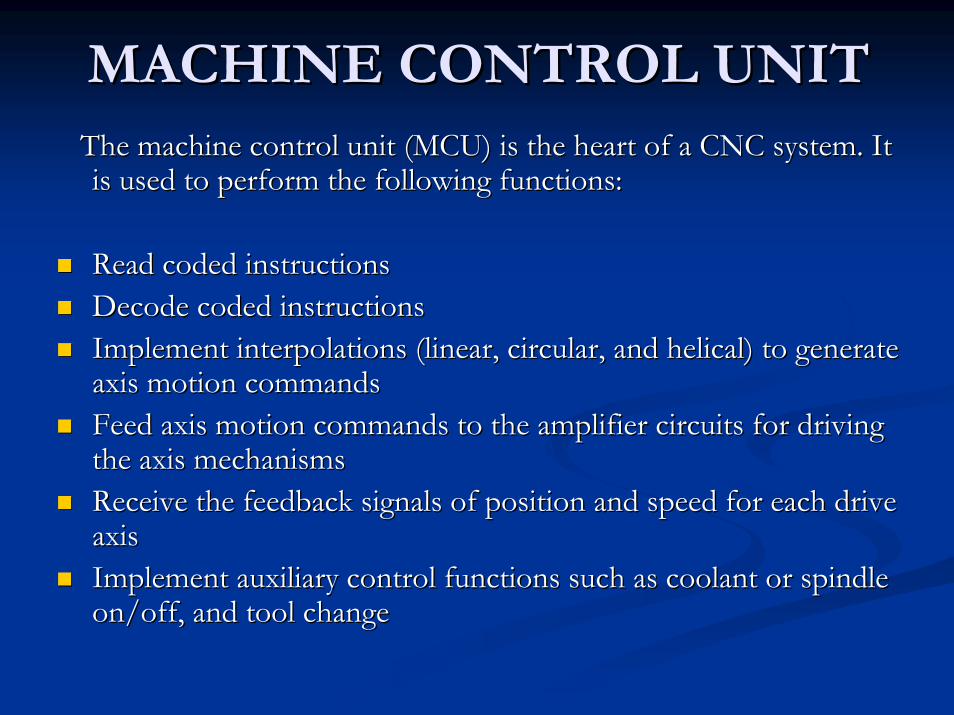
MACHINE CONTROL UNITMACHINE CONTROL UNITThe machine control unit (MCU) is the heart of a CNC system. It The machine control unit (MCU) is the heart of a CNC system. It is used to perform the following functions: is used to perform the following functions:
Read coded instructionsRead coded instructionsDecode coded instructions Decode coded instructions Implement interpolations (linear, circular, and helical) to geneImplement interpolations (linear, circular, and helical) to generate rate axis motion commands axis motion commands Feed axis motion commands to the amplifier circuits for driving Feed axis motion commands to the amplifier circuits for driving the axis mechanisms the axis mechanisms Receive the feedback signals of position and speed for each drivReceive the feedback signals of position and speed for each drive e axis axis Implement auxiliary control functions such as coolant or spindleImplement auxiliary control functions such as coolant or spindleon/off, and tool changeon/off, and tool change
TYPES of CNC CONTROL TYPES of CNC CONTROL SYSTEMSSYSTEMS
OpenOpen--loop controlloop controlClosedClosed--loop controlloop control

OPENOPEN--LOOP CONTROL LOOP CONTROL SYSTEMSYSTEM
In openIn open--loop control system loop control system step step motorsmotors areare usedusedStep Step motors are driven by electric pulsesmotors are driven by electric pulsesEvery pulse rotates the Every pulse rotates the motor motor spindle through spindle through a a certain certain amountamountBy counting the pulsesBy counting the pulses, , the amount the amount of of motion motion can be can be controlledcontrolledNo No feedback signal for error correctionfeedback signal for error correctionLower positioning accuracy Lower positioning accuracy
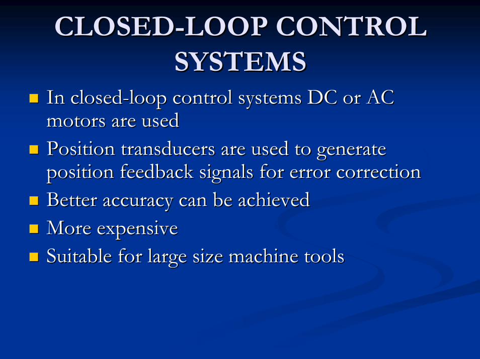
CLOSEDCLOSED--LOOP CONTROL LOOP CONTROL SYSTEMSSYSTEMS
In closedIn closed--loop control systems loop control systems DC DC or or AC AC motors are usedmotors are usedPosition transducers are used to generate Position transducers are used to generate position feedback signals for error correctionposition feedback signals for error correctionBetter accuracy Better accuracy can be can be achievedachievedMore expensiveMore expensiveSuitable for large Suitable for large size size machine toolsmachine tools
DRIVE SYSTEMDRIVE SYSTEM
A drive system consists of amplifier circuits, A drive system consists of amplifier circuits, steppingstepping motorsmotors or servomotorsor servomotors and ball leadand ball lead--screws. The MCU feeds control signals (position screws. The MCU feeds control signals (position and speed) of each axis to the amplifier circuits. and speed) of each axis to the amplifier circuits. The control signals are augmented to actuate The control signals are augmented to actuate steppingstepping motors which in turn rotate the ball motors which in turn rotate the ball leadlead--screws to position the machine table. screws to position the machine table.

STEPPING MOTORSSTEPPING MOTORS
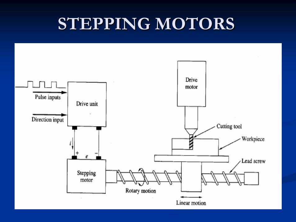
A stepping motor provides open-loop, digital control of the position of a work piece in a numerical control machine. The drive unit receives a direction input (cw or ccw) and pulse inputs. For each pulse it receives, the drive unitmanipulates the motor voltage and current, causing the motor shaft to rotate by a fixed angle (one step). The lead screw converts the rotary motion of the motor shaft into linear motion of the work piece .
STEPPING MOTORSSTEPPING MOTORS
RECIRCULATING BALL RECIRCULATING BALL SCREWSSCREWS
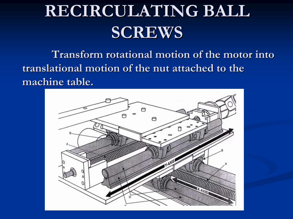
Transform rotational motion of the motor intoTransform rotational motion of the motor intotranslationaltranslational motion of the nut attached to the motion of the nut attached to the machine table.machine table.

RECIRCULATING BALL RECIRCULATING BALL SCREWSSCREWS
Accuracy of CNCmachines depends ontheir rigid construction, care in manufacturing, and the use of ball screws to almost eliminate slop in the screws used to move portions of the machine.

POSITIONINGPOSITIONINGThe positioning resolution of a ball screw drive mechanism is directly proportional to the smallest angle that the motor can turn.The smallest angle is controlled by the motor step size.Micro steps can be used to decrease the motor step size.CNC machines typically have resolutions of 0.0025 mmor better.
MACHINE TOOLMACHINE TOOL
CNC controls are used to control various types CNC controls are used to control various types of machine tools. Regardless of which type of of machine tools. Regardless of which type of machine tool is controlled, it always has a slide machine tool is controlled, it always has a slide table and a spindle to control of position and table and a spindle to control of position and speed. The machine table is controlled in the X speed. The machine table is controlled in the X and Y axes, while the spindle runs along the Z and Y axes, while the spindle runs along the Z axis. axis.

FEEDBACK SYSTEMFEEDBACK SYSTEM
The feedback system is also referred to as the The feedback system is also referred to as the measuring system. It uses position and speed measuring system. It uses position and speed transducers to continuously monitor the transducers to continuously monitor the position at which the cutting tool is located at position at which the cutting tool is located at any particular time. The MCU uses the any particular time. The MCU uses the difference between reference signals and difference between reference signals and feedback signals to generate the control signals feedback signals to generate the control signals for correcting position and speed errors. for correcting position and speed errors.

CNC MACHINES FEEDBACK CNC MACHINES FEEDBACK DEVICESDEVICES
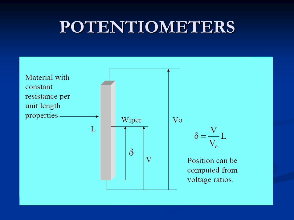
POTENTIOMETERSPOTENTIOMETERS

POTENTIOMETERSPOTENTIOMETERS

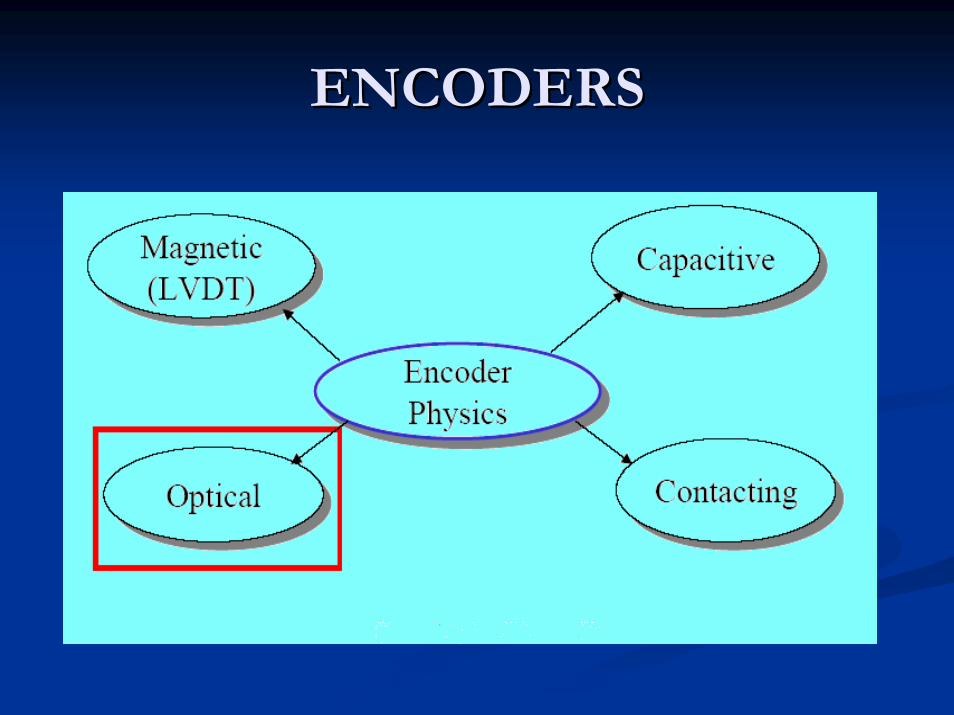
ENCODERSENCODERS
A device used to convert linear or rotational positionn information into an electrical output signal.
ENCODERSENCODERS

INDUSTRIAL APPLICATIONS of INDUSTRIAL APPLICATIONS of ENCODERSENCODERS
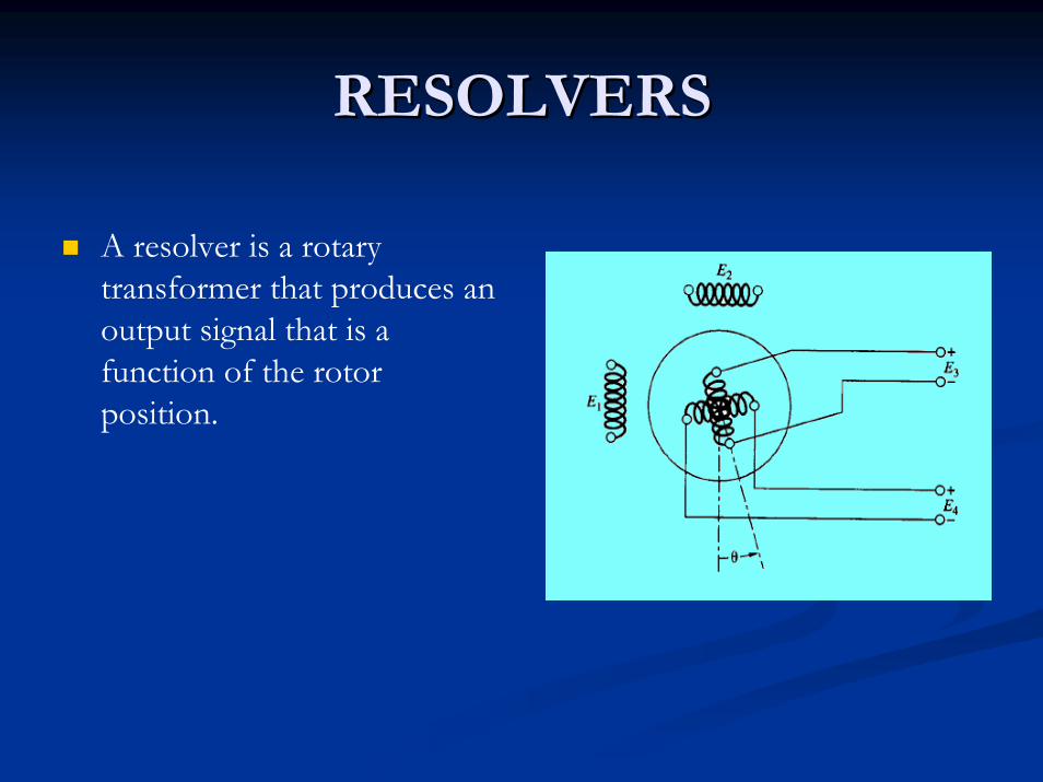
RESOLVERSRESOLVERS
A resolver is a rotary transformer that produces anoutput signal that is a function of the rotor position.
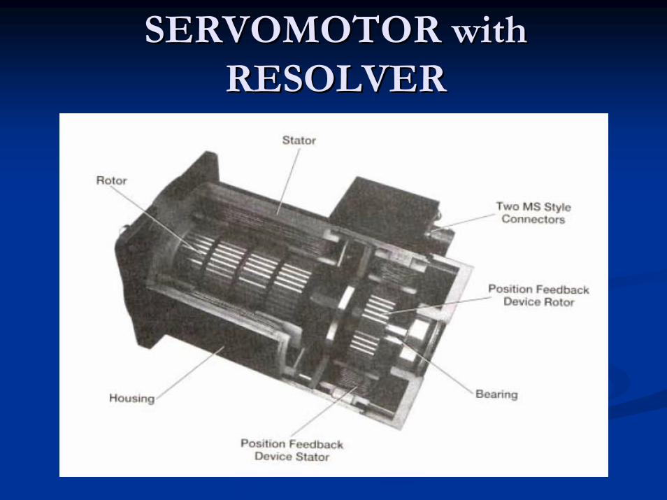
SERVOMOTOR SERVOMOTOR withwithRESOLVERRESOLVER

VELOCITY FEEDBACKVELOCITY FEEDBACK
Tachometers:
Electrical output is proportional to rate of angular rotation.Encoders, Resolvers, Potentiometers:
Number of pulses per time is proportional torate change of position.
CNC CUTTERSCNC CUTTERS
Turning center cutters Turning center cutters Machining center cuttersMachining center cutters
TURNING CENTER TURNING CENTER CUTTERSCUTTERS
Types of cutters used on CNC turning centersCarbides (and other hard materials) insert turning and boring toolsCeramicsHigh Speed Steel (HSS) drills and taps
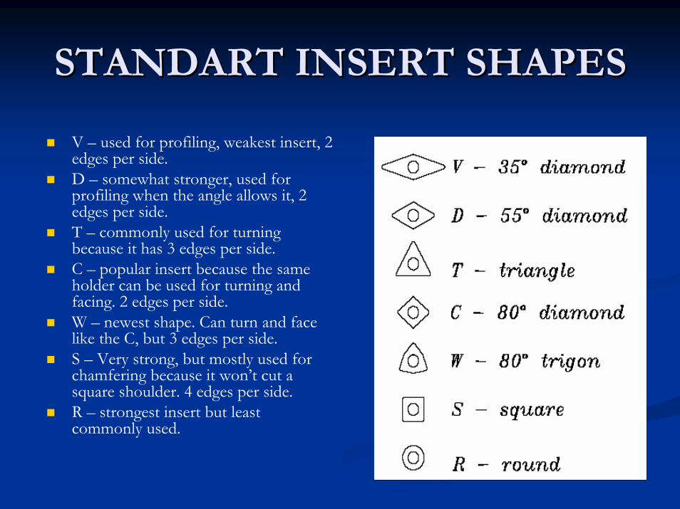
STANDART INSERT SHAPESSTANDART INSERT SHAPES
V – used for profiling, weakest insert, 2edges per side.D – somewhat stronger, used for profiling when the angle allows it, 2 edges per side.T – commonly used for turning because it has 3 edges per side.C – popular insert because the same holder can be used for turning and facing. 2 edges per side.W – newest shape. Can turn and face like the C, but 3 edges per side.S – Very strong, but mostly used forchamfering because it won’t cut a square shoulder. 4 edges per side.R – strongest insert but least commonly used.
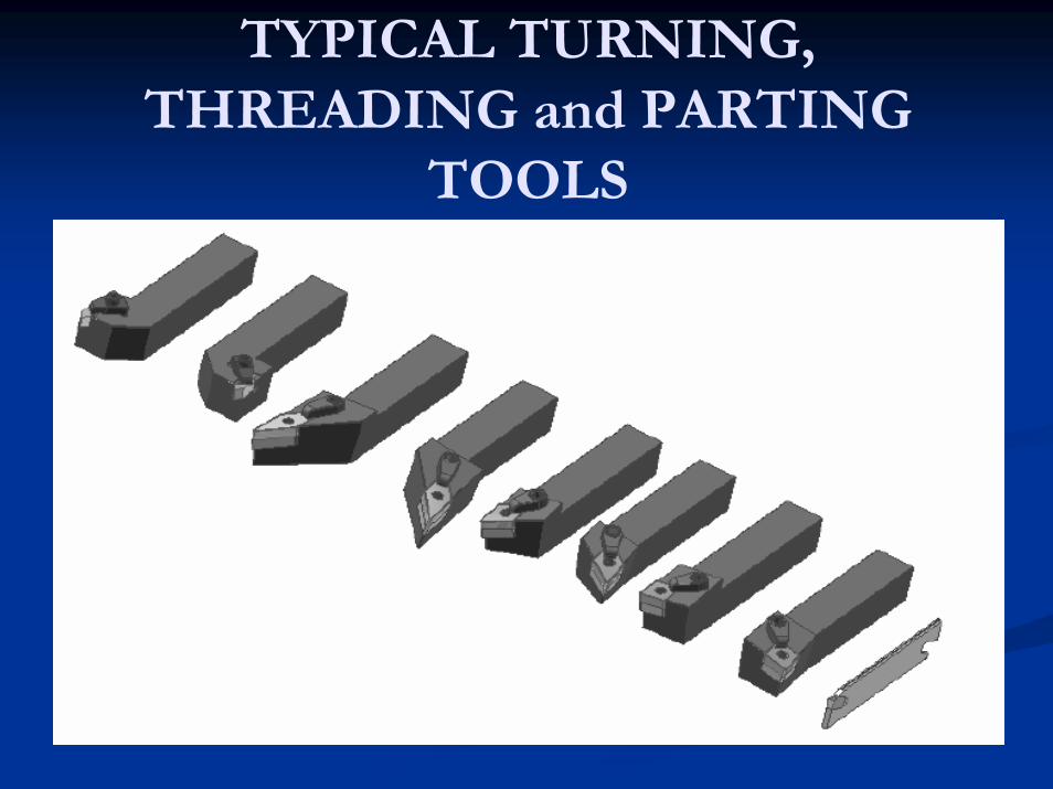
TYPICAL TURNING,THREADING and PARTING
TOOLS
MACHINING CENTER MACHINING CENTER CUTTING TOOLSCUTTING TOOLS
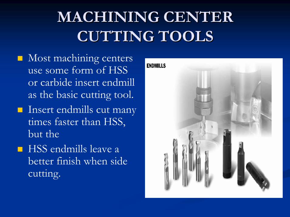
Most machining centers use some form of HSS or carbide insert endmillas the basic cutting tool.Insert endmills cut many times faster than HSS, but theHSS endmills leave abetter finish when side cutting.

MACHINING CENTER MACHINING CENTER CUTTING TOOLS (CUTTING TOOLS (contcont’’dd))
Facemills flatten largesurfaces quickly and withan excellent finish. Notice the engine block being finished in one pass with a large cutter.

MACHINING CENTER MACHINING CENTER CUTTING TOOLS (CUTTING TOOLS (contcont’’dd))
Ball endmills (both HSS and insert) are used for a variety of profilingoperations such as the mold shown in the picture.Slitting and side cutters are used when deep, narrow slots must be cut.
MACHINING CENTER MACHINING CENTER CUTTING TOOLS (CUTTING TOOLS (contcont’’dd))
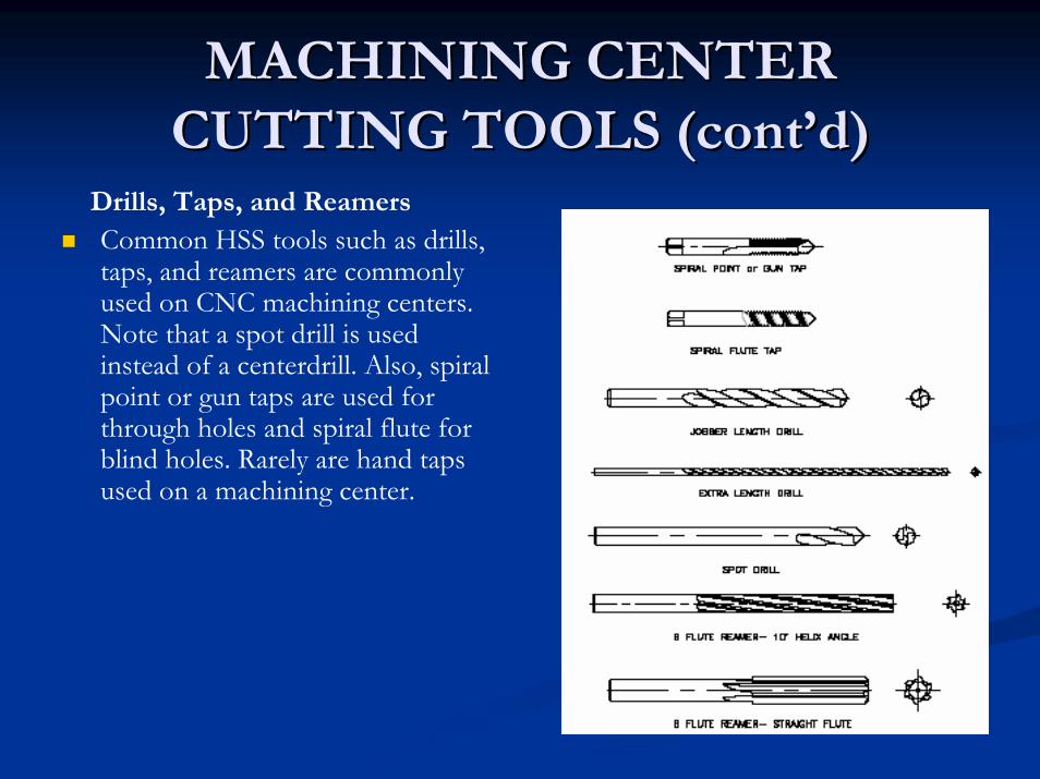
Drills, Taps, and ReamersCommon HSS tools such as drills,taps, and reamers are commonlyused on CNC machining centers.Note that a spot drill is used instead of a centerdrill. Also, spiral point or gun taps are used for through holes and spiral flute for blind holes. Rarely are hand taps used on a machining center.
TOOL HOLDERSTOOL HOLDERS
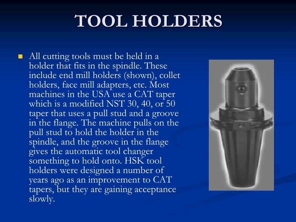
All cutting tools must be held in a holder that fits in the spindle. These include end mill holders (shown), collet holders, face mill adapters, etc. Most machines in the USA use a CAT taper which is a modified NST 30, 40, or 50 taper that uses a pull stud and a groove in the flange. The machine pulls on the pull stud to hold the holder in the spindle, and the groove in the flange gives the automatic tool changer something to hold onto. HSK tool holders were designed a number of years ago as an improvement to CAT tapers, but they are gaining acceptanceslowly.