introduction to dstv dish observations - home -...
TRANSCRIPT
Introduction to DSTV Dish Observations
Alet de Witt AVN Technical Training 2016
Outline
• Theory:
- Radio Waves
- Radio Telescope Antennas
- Angular Sizes
- Brightness Temperature and Antenna Temperature
- Detecting Radio Emission from Space
• Experimental Procedure:
- Measure the angular diameter of the Sun
- A simple radio telescope
- Calibrating the radio telescope
- Calculate the brightness temperature of the Sun
- More fun activities

Theory: Radio Waves
• Radio waves are electromagnetic waves and travel at the speed of light c = νλ
• The microwave band is the short wavelength part of the radio band and covers 1 - 30 cm wavelength.

Theory: Radio Telescope Antennas
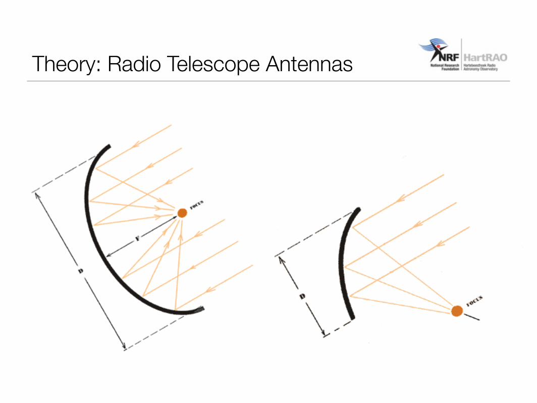
• A “classic” radio telescope for use in the microwave band has a circular parabolic reflector with a feed horn at the focus to collect the incoming microwaves and pass them to transistor amplifiers in the receiver.
• A DSTV satellite dish also works in this way. It can be used as a mini radio telescope by replacing the DSTV decoder with a radiometer for measuring the signal strength.
Theory: Radio Telescope Antennas
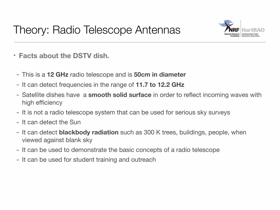
• Facts about the DSTV dish.
- This is a 12 GHz radio telescope and is 50cm in diameter - It can detect frequencies in the range of 11.7 to 12.2 GHz- Satellite dishes have a smooth solid surface in order to reflect incoming waves with
high efficiency- It is not a radio telescope system that can be used for serious sky surveys- It can detect the Sun- It can detect blackbody radiation such as 300 K trees, buildings, people, when
viewed against blank sky - It can be used to demonstrate the basic concepts of a radio telescope- It can be used for student training and outreach
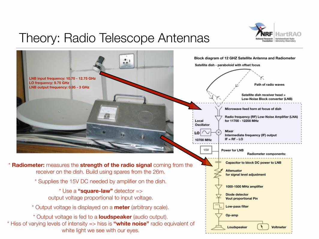
* Radiometer: measures the strength of the radio signal coming from the receiver on the dish. Build using spares from the 26m. * Supplies the 15V DC needed by amplifier on the dish.
* Use a “square-law” detector => output voltage proportional to input voltage.
* Output voltage is displayed on a meter (arbitrary scale). * Output voltage is fed to a loudspeaker (audio output).
* Hiss of varying levels of intensity => hiss is “white noise” radio equivalent of white light we see with our eyes.
Theory: Radio Telescope Antennas
Capacitor to block DC power to LNB
Attenuatorfor signal level adjustment
1000-1500 MHz amplifier
Diode detector Vout proportional Pin
Low-pass filter
Op-amp
Loudspeaker Voltmeter
Radiometer components:Power for LNB15V
Microwave feed horn at focus of dish
Radio frequency (RF) Low-Noise Amplifier (LNA) for 11700 - 12200 MHz
MixerIntermediate frequency (IF) outputIF = RF - LO
Local Oscillator
10700 MHz
Satellite dish - paraboloid with offset focus
LO
Path of radio waves
Satellite dish receiver head = Low-Noise Block converter (LNB)
Block diagram of 12 GHZ Satellite Antenna and Radiometer
LNB input frequency: 10.70 - 12.75 GHzLO frequency: 9.75 GHz LNB output frequency: 0.95 - 3 GHz
The diffraction pattern produced by a circular
focusing lens or reflectorA focusing lens or
reflector with a circular aperture
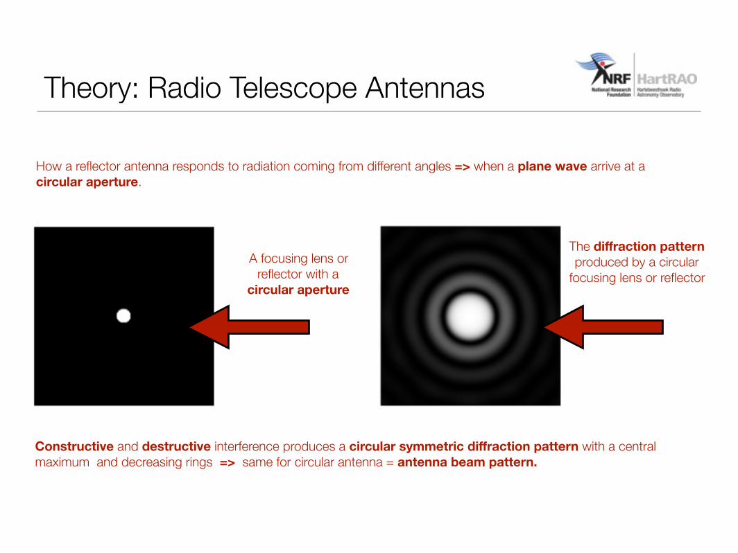
How a reflector antenna responds to radiation coming from different angles => when a plane wave arrive at a circular aperture.
Theory: Radio Telescope Antennas
Constructive and destructive interference produces a circular symmetric diffraction pattern with a central maximum and decreasing rings => same for circular antenna = antenna beam pattern.

Antenna Beam Pattern
DSTV dish => 0.75 based on measurements at HartRAO
Theory: Radio Telescope Antennas
Angle from Beam Axis [wavelength/diameter] (radians)
Rel
ativ
e G
ain
- lin
ear S
cale
The beam cross-section through the beam pattern of an ideal antenna and a practically
realisable antenna, shown with a linear vertical scale (unblocked aperture).
FWHM = ~ 1.2λ/D [radians] => the “beamwidth” of the antenna
BWFN => first min or null in pattern ~ 2.4λ/D [radians]
“Ideal” antenna would produce a beam that captures 100% of the incoming energy in the
main beam and have no sidelobes => main beam efficiency = 1.0 (usually between
0.6 - 0.8)

Theory: Radio Telescope Antennas
The power pattern is normalized at its most sensitive direction (ideally, this will be along the physical axis of the antenna)P(0,0) = 1
The power pattern is the measure of the response of a telescope to a point source as a function of angle. A hypothetical power pattern (in one angular dimension) is shown above.
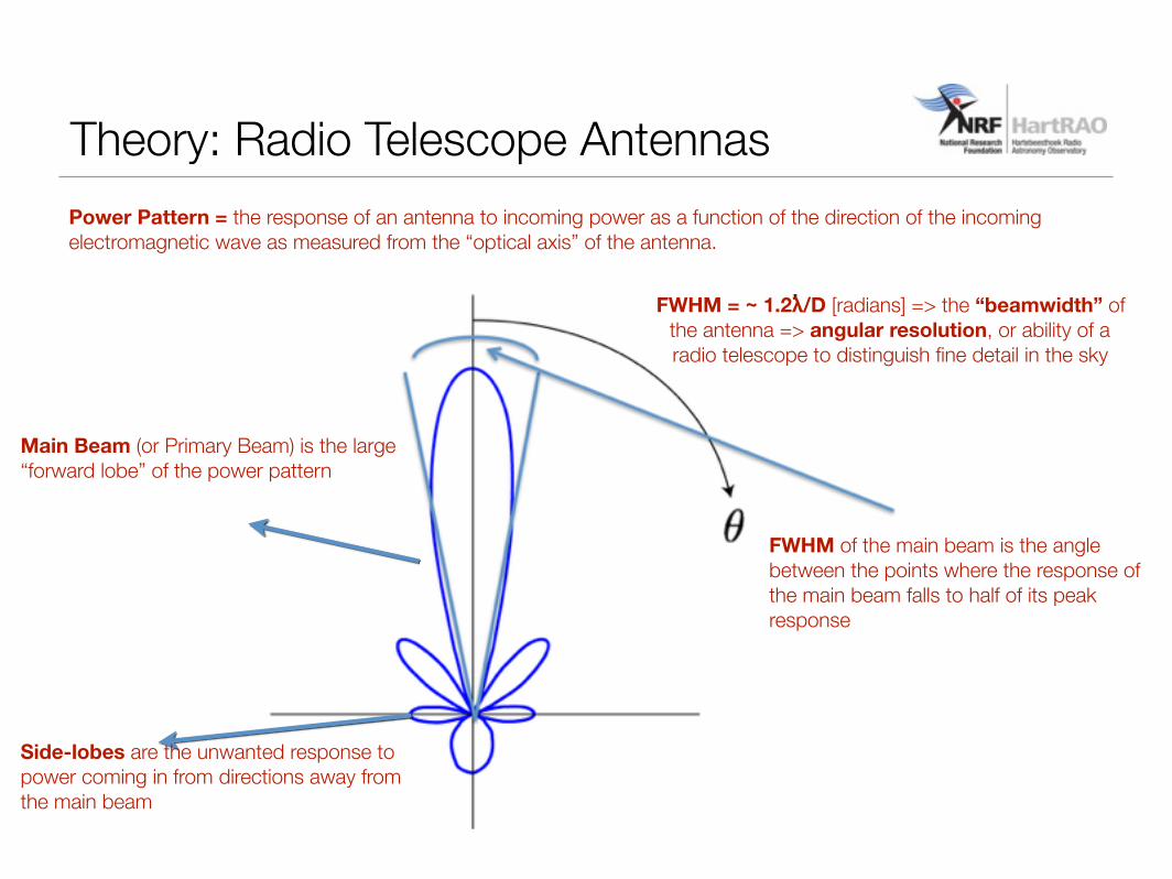
Theory: Radio Telescope AntennasPower Pattern = the response of an antenna to incoming power as a function of the direction of the incoming electromagnetic wave as measured from the “optical axis” of the antenna.
Main Beam (or Primary Beam) is the large “forward lobe” of the power pattern
Side-lobes are the unwanted response to power coming in from directions away from the main beam
FWHM of the main beam is the angle between the points where the response of the main beam falls to half of its peak response
FWHM = ~ 1.2λ/D [radians] => the “beamwidth” of the antenna => angular resolution, or ability of a radio telescope to distinguish fine detail in the sky
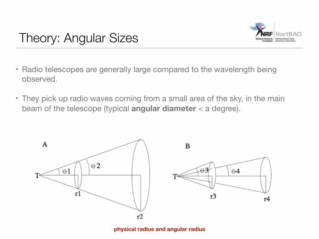
• Radio telescopes are generally large compared to the wavelength being observed.
• They pick up radio waves coming from a small area of the sky, in the main beam of the telescope (typical angular diameter < a degree).
Theory: Angular Sizes
physical radius and angular radius
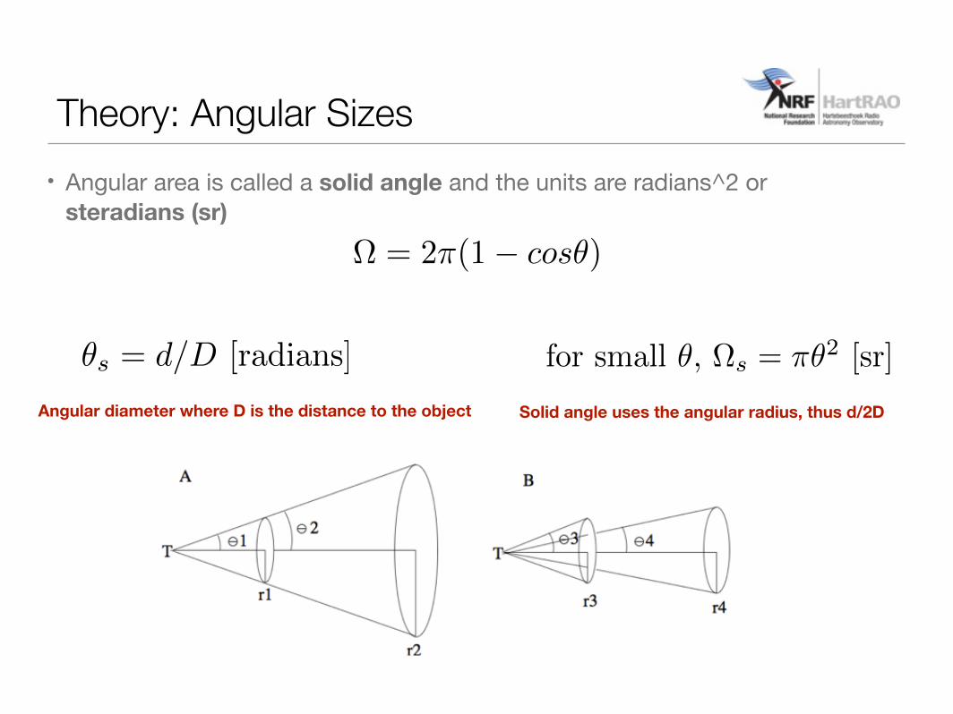
• Angular area is called a solid angle and the units are radians^2 or steradians (sr)
Theory: Angular Sizes
✓s = d/D [radians]
⌦ = 2⇡(1� cos✓)
for small ✓, ⌦s = ⇡✓2 [sr]
Angular diameter where D is the distance to the object Solid angle uses the angular radius, thus d/2D
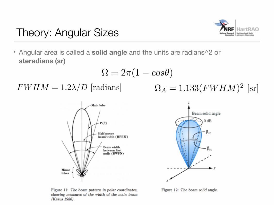
Theory: Angular Sizes
⌦ = 2⇡(1� cos✓)
⌦A = 1.133(FWHM)2 [sr]
• Angular area is called a solid angle and the units are radians^2 or steradians (sr)
FWHM = 1.2�/D [radians]
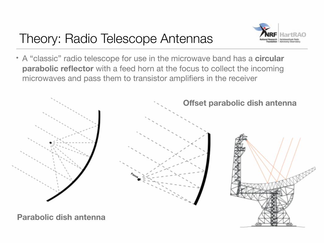
Parabolic dish antenna
Offset parabolic dish antenna
• A “classic” radio telescope for use in the microwave band has a circular parabolic reflector with a feed horn at the focus to collect the incoming microwaves and pass them to transistor amplifiers in the receiver
Theory: Radio Telescope Antennas
Theory: Radio Telescope Antennas
Theory: Radio Telescope Antennas

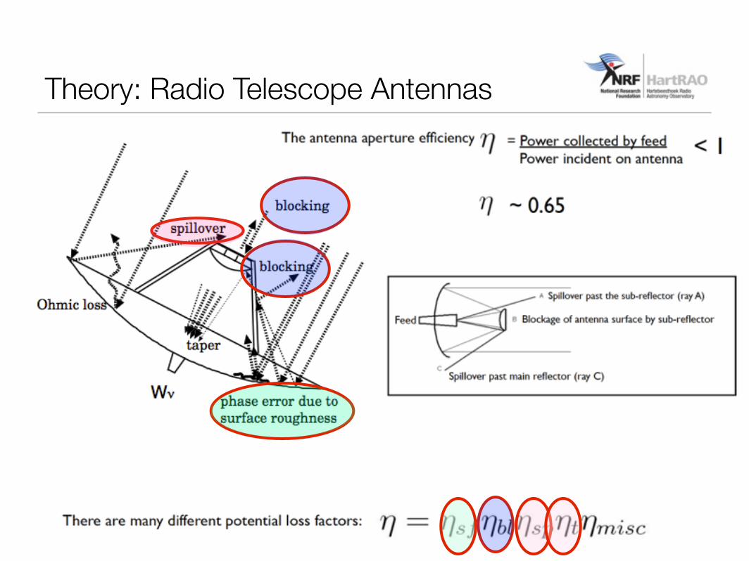
Theory: Radio Telescope AntennasDeformations and irregularities on the surface which can cause errors in phase across the aperture. These phase
imperfection transfer some power from the main beam in to the sidelobes. This represents a loss of efficiency.
Radiation Cooling
Solar Flux
Gravity
Wind
Ambient TemperatureChange
�sf = e�(4��/�)2
Ruze formula for surface efficiency, where sigma is the rms error in the surface of the antenna.
HartRAO 26m Teleacope: rms error of 0.5mm, can go up to 22 GHz or 1.3 cm
The rms error over the surface was about 2.5 mm, which prevented useful operation below a wavelength
of 2cm.
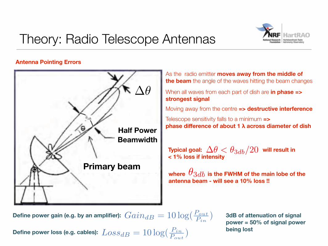
As the radio emitter moves away from the middle of the beam the angle of the waves hitting the beam changes
When all waves from each part of dish are in phase => strongest signalMoving away from the centre => destructive interference
Telescope sensitivity falls to a minimum => phase difference of about 1 λ across diameter of dish
Theory: Radio Telescope Antennas
Pointing accuracy
Half PowerBeamwidth
Primary beam
��
Antenna Pointing Errors
Typical goal: will result in < 1% loss if intensity
�3dbwhere is the FWHM of the main lobe of the antenna beam - will see a 10% loss !!
�� < �3db/20
Define power gain (e.g. by an amplifier):
Define power loss (e.g. cables):
GaindB = 10 log(PoutPin
)
LossdB = 10 log( PinPout
)
3dB of attenuation of signal power = 50% of signal power being lost
• The speed (0.5deg/s - Hart26m) at which an antenna can move from one part of the sky to another, settle time and time to accelerate to full speed is also an important performance factor (1) observing efficiency(2) calibration - e.g. phase referencing
• A rigid structure is also important (1) minimises antenna settle time (the time it takes for an antenna to firmly settle on a source)(2) maintains the optical geometry of the telescope
Theory: Angular Sizes
Theory: TB and TA
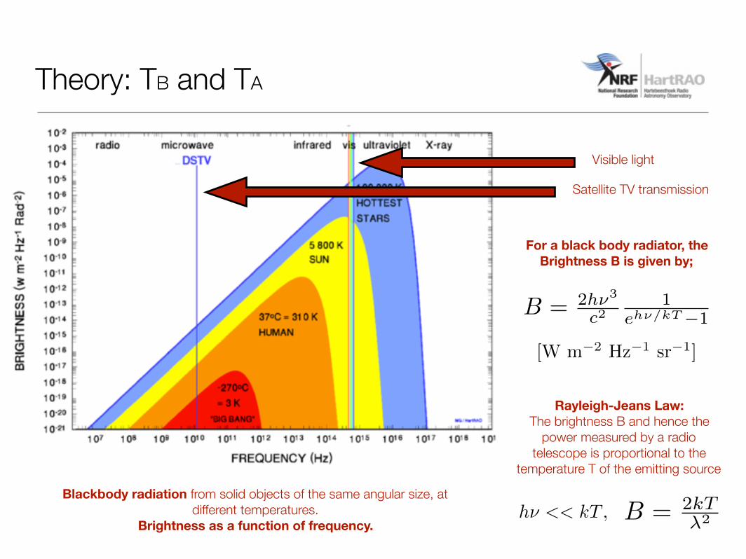
Blackbody radiation from solid objects of the same angular size, at different temperatures.
Brightness as a function of frequency.
Visible light
Satellite TV transmission
Rayleigh-Jeans Law:The brightness B and hence the
power measured by a radio telescope is proportional to the
temperature T of the emitting source
B = 2h⌫3
c21
eh⌫/kT�1
[W m�2 Hz�1 sr�1]
For a black body radiator, the Brightness B is given by;
B = 2kT�2h⌫ << kT ,
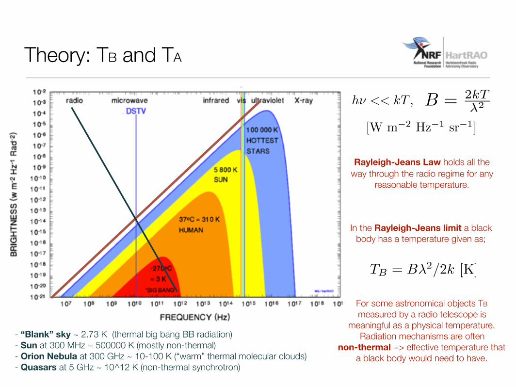
[W m�2 Hz�1 sr�1]
B = 2kT�2h⌫ << kT ,
Rayleigh-Jeans Law holds all the way through the radio regime for any
reasonable temperature.
In the Rayleigh-Jeans limit a black body has a temperature given as;
TB = B�2/2k [K]
For some astronomical objects TB measured by a radio telescope is
meaningful as a physical temperature. Radiation mechanisms are often
non-thermal => effective temperature that a black body would need to have.
- “Blank” sky ~ 2.73 K (thermal big bang BB radiation)- Sun at 300 MHz = 500000 K (mostly non-thermal) - Orion Nebula at 300 GHz ~ 10-100 K (“warm” thermal molecular clouds) - Quasars at 5 GHz ~ 10^12 K (non-thermal synchrotron)
Theory: TB and TA
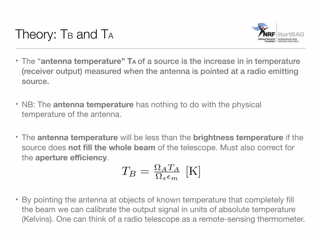
• The “antenna temperature” TA of a source is the increase in in temperature (receiver output) measured when the antenna is pointed at a radio emitting source.
• NB: The antenna temperature has nothing to do with the physical temperature of the antenna.
• The antenna temperature will be less than the brightness temperature if the source does not fill the whole beam of the telescope. Must also correct for the aperture efficiency.
• By pointing the antenna at objects of known temperature that completely fill the beam we can calibrate the output signal in units of absolute temperature (Kelvins). One can think of a radio telescope as a remote-sensing thermometer.
TB = ⌦ATA⌦s✏m
[K]
Theory: TB and TA

• When the telescope looks at a radio source in the sky, the receiver output is the sum of radio waves received from several different sources:
Theory: Detecting Radio Emission
Tsys = TBcmb + TA + Tat + Twv + Tg + TR [K]
CMB radiation coming fromevery direction in space. ~ 2.7 K at 1.4 or 4 GHz,
reducing to 2.5 K at 12 GHz (but at lower frequencies
the radio emission from the Milky Way becomes increasingly stronger.)
The emission from the radio source we want to measure, which
produces the antenna temperature.
Radiation from the dry atmosphere. Adds about 1 K.
Radiation from the water vapour in the atmosphere.
At 12 GHz adds 1 - 2 K, depending on the humidity.
The radiation the feed receives through the antenna sidelobes from
the (warm ~ 290 K) ground. Adds 5 - 15 K pointing straight up at zenith, and increases when pointing
close to the horizon.
The amplifiers in the antenna produce their own electronic noise, receiver
noise temperature.
The sum of these parts is called the system temperature Sky temperature Tsky ~ 10 K

Experimental Procedure:
• Turn the DSTV dish to blank sky. Listen to the speaker or look at the meter.
• Now turn the DSTV dish towards the ground and see/hear the difference. REMEMBER The noise level depends on the temperature of the object.
• Sky – shows lowest signal level. Note that when aimed at different parts of the sky the signal level hardly changes. This means that it is not sensitive enough to detect stars.
• Remember that blank sky is about 10 K while the ground is about 300 K !

• Turn the DSTV dish towards the Sun.
Experimental Procedure:
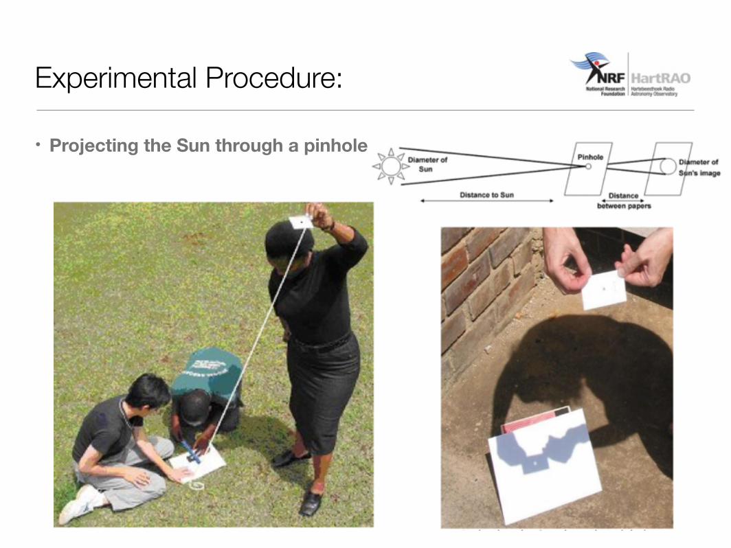
• Projecting the Sun through a pinhole
Experimental Procedure:

• Calibrating the radio telescope:
• Why isn’t the Sun, with all its enormous energy (temperature of 6000 K), pinning the meter?
• It turns out that the DSTV dish has a beam width of 3.4° while the Sun appears to be only 0.5° in our sky. Thus the area of the dish occupied by the sun is small and the signal appears weaker than the ground at 300K.
• FWHM (beamwidth) => ~ 1.2λ/D (λ = 12 GHz = 2.5 cm, D = 50 cm).
• Measuring the diameter of the Sun => θ = d/2D (diameter = 0.5°).
• We could fit ~66 Suns into the beam of the dish (ratio of the angular size of the source to the angular size of the Sun).
⌦A = 1.133(FWHM)2 [sr]
⌦s = ⇡✓2 [sr]
Experimental Procedure:
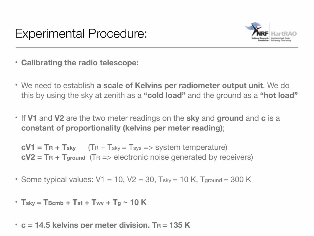
• Calibrating the radio telescope:
• We need to establish a scale of Kelvins per radiometer output unit. We do this by using the sky at zenith as a “cold load” and the ground as a “hot load”
• If V1 and V2 are the two meter readings on the sky and ground and c is a constant of proportionality (kelvins per meter reading);cV1 = TR + Tsky (TR + Tsky = Tsys => system temperature)cV2 = TR + Tground (TR => electronic noise generated by receivers)
• Some typical values: V1 = 10, V2 = 30, Tsky = 10 K, Tground = 300 K
• Tsky = TBcmb + Tat + Twv + Tg ~ 10 K
• c = 14.5 kelvins per meter division, TR = 135 K
Experimental Procedure:
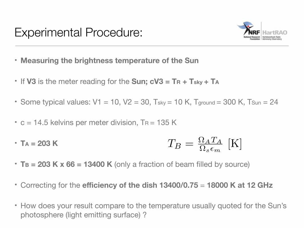
• Measuring the brightness temperature of the Sun
• If V3 is the meter reading for the Sun; cV3 = TR + Tsky + TA
• Some typical values: V1 = 10, V2 = 30, Tsky = 10 K, Tground = 300 K, TSun = 24
• c = 14.5 kelvins per meter division, TR = 135 K
• TA = 203 K
• TB = 203 K x 66 = 13400 K (only a fraction of beam filled by source)
• Correcting for the efficiency of the dish 13400/0.75 = 18000 K at 12 GHz
• How does your result compare to the temperature usually quoted for the Sun’s photosphere (light emitting surface) ?
TB = ⌦ATA⌦s✏m
[K]
Experimental Procedure:
Experimental Procedure:
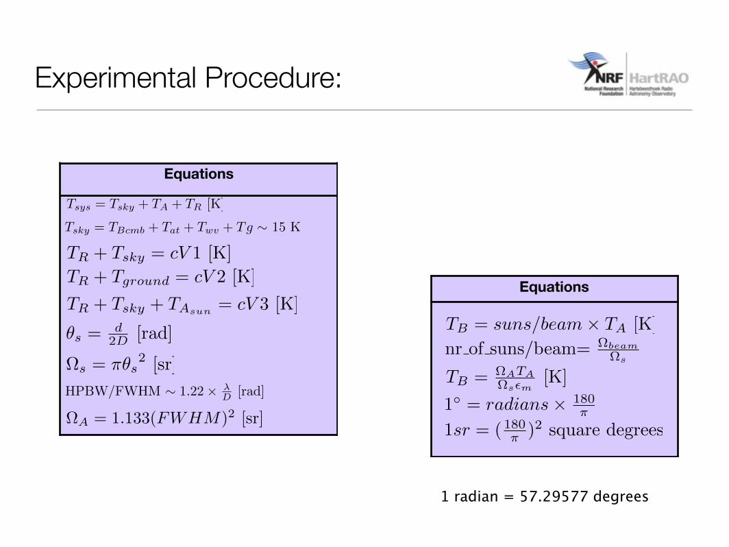
1 radian = 57.29577 degrees Equations
1sr = ( 180⇡ )2 square degrees
TB = ⌦ATA⌦s�m
[K]
nr of suns/beam=
⌦beam⌦s
TB = suns/beam⇥ TA [K]
1� = radians⇥ 180⇡
Equations
TR + Tsky = cV 1 [K]TR
+ Tground
= cV 2 [K]
Tsky = TBcmb + Tat + Twv + Tg ⇠ 15 K
Tsys = Tsky + TA + TR [K]
TR + Tsky + TAsun = cV 3 [K]
✓s =d2D [rad]
�s = ⇡✓s2 [sr]
1 radian = 57.29577 degrees
HPBW/FWHM ⇠ 1.22⇥ �D [rad]
⌦A = 1.133(FWHM)2 [sr]
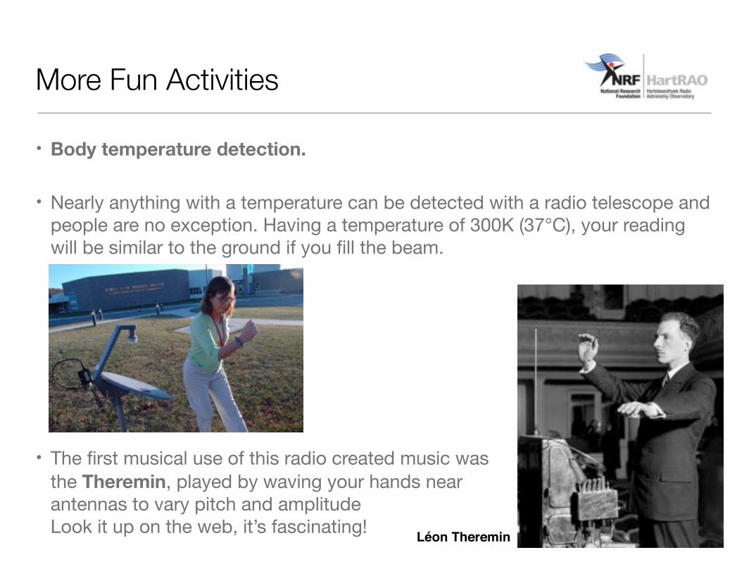
• Body temperature detection.
• Nearly anything with a temperature can be detected with a radio telescope and people are no exception. Having a temperature of 300K (37°C), your reading will be similar to the ground if you fill the beam.
• The first musical use of this radio created music was the Theremin, played by waving your hands near antennas to vary pitch and amplitudeLook it up on the web, it’s fascinating! Léon Theremin
More Fun Activities
• Satellite detection.
• Many geo-stationary satellites are in orbit above the Earth and many transmit radio signals. Remember though that the sun is a broadband (extremely!) transmitter whereas the satellite is a very narrow beam transmitter.
• Most of these satellites orbit above the equator so figure out where your celestial equator is by taking you latitude and subtracting it from 90°. This is a rough altitude to look for satellites.
More Fun Activities
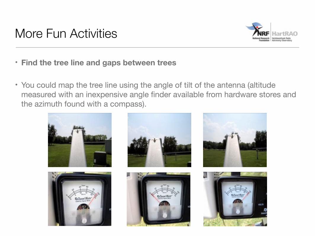
• Find the tree line and gaps between trees
• You could map the tree line using the angle of tilt of the antenna (altitude measured with an inexpensive angle finder available from hardware stores and the azimuth found with a compass).
More Fun Activities
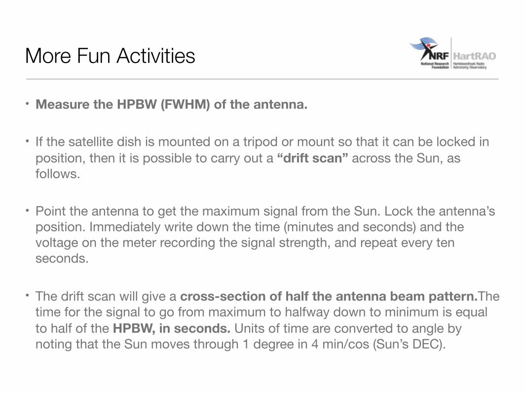
• Measure the HPBW (FWHM) of the antenna.
• If the satellite dish is mounted on a tripod or mount so that it can be locked in position, then it is possible to carry out a “drift scan” across the Sun, as follows.
• Point the antenna to get the maximum signal from the Sun. Lock the antenna’s position. Immediately write down the time (minutes and seconds) and the voltage on the meter recording the signal strength, and repeat every ten seconds.
• The drift scan will give a cross-section of half the antenna beam pattern.The time for the signal to go from maximum to halfway down to minimum is equal to half of the HPBW, in seconds. Units of time are converted to angle by noting that the Sun moves through 1 degree in 4 min/cos (Sun’s DEC).
More Fun Activities
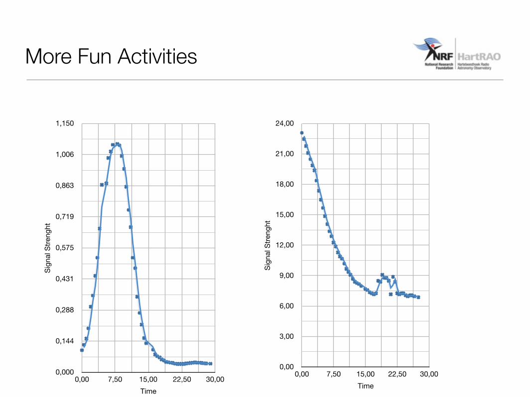
Sign
al S
treng
ht
0,000
0,144
0,288
0,431
0,575
0,719
0,863
1,006
1,150
Time 0,00 7,50 15,00 22,50 30,00
Sign
al S
treng
ht
0,00
3,00
6,00
9,00
12,00
15,00
18,00
21,00
24,00
Time 0,00 7,50 15,00 22,50 30,00
More Fun Activities