introduction to enterprise wlan fundamentalsfaculty.ccc.edu/mmoizuddin/cisco live...
TRANSCRIPT
© 2006, Cisco Systems, Inc. All rights reserved.Presentation_ID.scr
1
© 2008 Cisco Systems, Inc. All rights reserved. Cisco Public 1BRKAGG-101014589_04_2008_c1
© 2008 Cisco Systems, Inc. All rights reserved. Cisco PublicBRKAGG-101014589_04_2008_c1 2
Introduction to Enterprise WLAN Fundamentals
BRKAGG-1010

© 2006, Cisco Systems, Inc. All rights reserved.Presentation_ID.scr
2
© 2008 Cisco Systems, Inc. All rights reserved. Cisco Public 3BRKAGG-101014589_04_2008_c1
Session Objectives
Review basic 802.11 concepts
Understand the Lightweight Access Point Protocol (LWAPP) and the Unified Architecture
Understand the features of Cisco® Unified Wireless Networks (CUWN)
Introduction to 802.11n
WCS new feature and location features
Review CUWN product portfolio—understanding and selecting the right products for deployment
Configuration examples
© 2008 Cisco Systems, Inc. All rights reserved. Cisco Public 4BRKAGG-101014589_04_2008_c1
Overall Session Agenda
Introduction/802.11 Refresher
What Is LWAPP
Understanding Features
Introduction 802.11n
Product Selection in various Deployment Scenarios
Configuring a Simple Network—Examples
Summary and Takeaways
References

© 2006, Cisco Systems, Inc. All rights reserved.Presentation_ID.scr
3
© 2008 Cisco Systems, Inc. All rights reserved. Cisco Public 5BRKAGG-101014589_04_2008_c1
802.11 Refresher
© 2008 Cisco Systems, Inc. All rights reserved. Cisco Public 6BRKAGG-101014589_04_2008_c1
802.11’s Access Rules
Distributed Coordinated Function (DCF)Transmission rules followed by all clients
Carrier Sense Multiple Access with Collision Avoidance (CSMA/CA)
Responsible for mediating access to the air
DCF Is 802.11’s Rules of the Road
CSMA/CA Is 802.11’s Traffic Lights

© 2006, Cisco Systems, Inc. All rights reserved.Presentation_ID.scr
4
© 2008 Cisco Systems, Inc. All rights reserved. Cisco Public 7BRKAGG-101014589_04_2008_c1
802.11’s Access Rules
Distributed Coordinated Function (DCF)Transmission rules followed by all clients
Interframe spaces (IFS) are used to ‘prioritize’ traffic
IFS are very short delays before transmissions are allowed
The Short Interframe Space (SIFS) is used for transmission of management and control frames
The DFS Interframe Space (DIFS) is used before the transmission of data frames
CSMA/CA allows ‘peaceful’ coexistence of many devices trying to transmit simultaneously
© 2008 Cisco Systems, Inc. All rights reserved. Cisco Public 8BRKAGG-101014589_04_2008_c1
802.11’s Access Mediation
Carrier sense multiple access with collision avoidanceCSMA/CA responsible for mediating access to the air
Reduces the likelihood of a transmission collision
Provides probabilistically fair access to every device
CSMA/CA provides a framework clients follow before being allowed to transmit: ‘Listen before talk’
Wait the appropriate interframe space (SIFS or DIFS)
If medium is free, wait to make sure no one else is beginning to transmit (this is called the ‘backoff’)
If medium is still free after ‘backoff,’ then transmit
ContentionWindow
Time (t)
IFS Transmission

© 2006, Cisco Systems, Inc. All rights reserved.Presentation_ID.scr
5
© 2008 Cisco Systems, Inc. All rights reserved. Cisco Public 9BRKAGG-101014589_04_2008_c1
Dissecting CSMA/CA
Two sensing methodsPhysical Carrier Sense
Directed management and data frames include a duration ID
Used to indicate to nonsending/receiving devices how long the medium will be occupied
Virtual Carrier Sense
Clients then set a timer: Network Allocation Vector (NAV)
This timer is decremented, and once at 0, physical carrier sense is invoked and the process starts over
Only when both sensing mechanisms indicate the air is free do clients then begin to prepare to wait before transmission
‘Carrier Sense’ allows more than one device to ‘talk’ on the network, granting ‘multiple access’
© 2008 Cisco Systems, Inc. All rights reserved. Cisco Public 10BRKAGG-101014589_04_2008_c1
Dissecting CSMA/CA (Cont.)
After the medium is determined free, the transmitting station waits the appropriate IFS
The ‘Contention Window’ then starts when the station selects a random backoff duration
Backoff is derived by multiplying slot time (20 μs for 11b, 9 μs for 11 a/g) by a ‘randomly’ selected number between 0 and a CWmin (31 for 11 b/g, 15 for 11a)
© 2006, Cisco Systems, Inc. All rights reserved.Presentation_ID.scr
6
© 2008 Cisco Systems, Inc. All rights reserved. Cisco Public 11BRKAGG-101014589_04_2008_c1
Why QoS for WLAN?
Wireless is fundamentally different from wiredFar more stringent bandwidth limitations
Limited spectrum (few nonoverlapping channels)
Half-duplex medium
Every directed data and management frame is ACK’d
‘Listen Before Talk’ contention model
This all makes WLAN highly susceptible to latency and jitter
Can’t really ‘throw bandwidth’ at the problem, either
© 2008 Cisco Systems, Inc. All rights reserved. Cisco Public 12BRKAGG-101014589_04_2008_c1
…It Doesn’t
802.11 networks are completely egalitarianEvery device, AP included, has equal access to transmit
No device has precedence over any other
All transmissions for each individual device have the same access, transmitting in ‘FIFO’ fashion
No application has more transmit ‘weight’ than any other
Example: on a Single Laptop, a Voice Frame Has the Same Right to Transmit as Any Other Frame, Such as a Web Frame
Example: Voice Handsets Abide by the Same Access Rules as Laptops
© 2006, Cisco Systems, Inc. All rights reserved.Presentation_ID.scr
7
© 2008 Cisco Systems, Inc. All rights reserved. Cisco Public 13BRKAGG-101014589_04_2008_c1
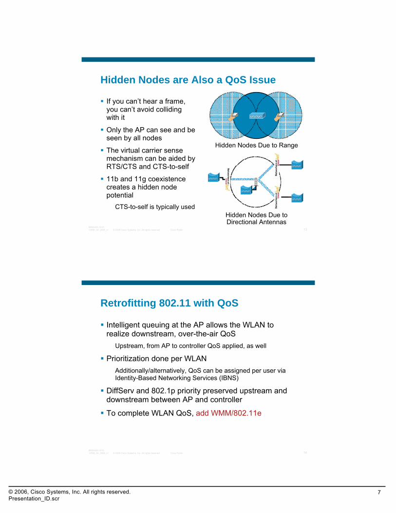
Hidden Nodes are Also a QoS Issue
If you can’t hear a frame, you can’t avoid colliding with it
Only the AP can see and be seen by all nodes
The virtual carrier sense mechanism can be aided by RTS/CTS and CTS-to-self
11b and 11g coexistence creates a hidden node potential
CTS-to-self is typically used
Hidden Nodes Due to Range
Hidden Nodes Due to Directional Antennas
© 2008 Cisco Systems, Inc. All rights reserved. Cisco Public 14BRKAGG-101014589_04_2008_c1
Retrofitting 802.11 with QoS
Intelligent queuing at the AP allows the WLAN to realize downstream, over-the-air QoS
Upstream, from AP to controller QoS applied, as well
Prioritization done per WLANAdditionally/alternatively, QoS can be assigned per user via Identity-Based Networking Services (IBNS)
DiffServ and 802.1p priority preserved upstream and downstream between AP and controller
To complete WLAN QoS, add WMM/802.11e

© 2006, Cisco Systems, Inc. All rights reserved.Presentation_ID.scr
8
© 2008 Cisco Systems, Inc. All rights reserved. Cisco Public 15BRKAGG-101014589_04_2008_c1
Lightweight Access Point Protocol (LWAPP)
© 2008 Cisco Systems, Inc. All rights reserved. Cisco Public 16BRKAGG-101014589_04_2008_c1
Ingress/Egress Point from/to Upstream
Switched/Routed Wired Network (802.1Q Trunk)
Switched/Routed Wired Network
Lightweight Access Point
Wireless LAN Controller
Cisco Centralized WLAN Model
Access Points Are “Lightweight”—Controlled by a Centralized WLAN Controller
Much of the Traditional WLAN Functionality Moved from
Access Points to Centralized WLAN Controller
LWAPP Defines Control Messaging and Data Encapsulation Between Access Points and
Centralized WLAN Controller
LWAPP Tunnel
Control MessagesData Encapsulation

© 2006, Cisco Systems, Inc. All rights reserved.Presentation_ID.scr
9
© 2008 Cisco Systems, Inc. All rights reserved. Cisco Public 17BRKAGG-101014589_04_2008_c1
Switched/Routed Wired Network
Cisco Centralized WLAN Model
Remote RF InterfaceReal-Time 802.11 MAC
RF Spectral AnalysisWLAN IDS Signature Analysis
Security ManagementQoS Policies Enforcement
Centralized Configuration, Firmware ManagementNorthbound Management Interfaces
LWAPP Carries All Communication Between Access Point and Controller
L2 Or L3 TransportMutual Authentication—x.509 Certificate-Based
LWAPP Control AES-CCM EncryptedData Encapsulation
Radio Resource ManagementMobility Management
Ingress/Egress Point from/to Upstream
Switched/Routed Wired Network (802.1Q Trunk)
Lightweight Access Point
Wireless LAN ControllerLWAPP Tunnel
Control MessagesData Encapsulation
© 2008 Cisco Systems, Inc. All rights reserved. Cisco Public 18BRKAGG-101014589_04_2008_c1
Layer-3 LWAPP Architecture
Access points require IP addressing
APs can communicate with WLC across routed boundaries
L3 LWAPP is more flexible than L2 LWAPP and all products support this LWAPP operational ‘flavor’
Layer 2/3 Wired Network—Single or Multiple
Broadcast Domains
Control Messages—UDP 12223Data Encapsulation—UDP 12222
Lightweight Access Point
Wireless LAN ControllerL3 LWAPP Tunnel
Ingress/Egress Point from/to Upstream
Switched/Routed Wired Network (802.1Q Trunk)

© 2006, Cisco Systems, Inc. All rights reserved.Presentation_ID.scr
10
© 2008 Cisco Systems, Inc. All rights reserved. Cisco Public 19BRKAGG-101014589_04_2008_c1
LWAPP State Machine (Simplified)
LWAPP defines a state machine that governs the AP and controller behaviorMajor states
Discovery—AP looks for a controllerJoin—AP attempts to establish a secured relationship with a controllerImage Data—AP downloads code from controllerConfig—AP receives configuration from controllerRun—AP and controller operate normally and service dataReset—AP clears state and starts over
Note: LWAPP/CAPWAP RFC defines other states
© 2008 Cisco Systems, Inc. All rights reserved. Cisco Public 20BRKAGG-101014589_04_2008_c1
LWAPP Operations—Client Connections
AP handles real-time 802.11 control and management
Non–real-time 802.11 handled at controller
Controller is the 802.1x authenticator and centrally stores client QoS, security context
802.11 data frames are encrypted/decrypted at the RF interface
“Action frames” are management frames as defined by 802.11

© 2006, Cisco Systems, Inc. All rights reserved.Presentation_ID.scr
11
© 2008 Cisco Systems, Inc. All rights reserved. Cisco Public 21BRKAGG-101014589_04_2008_c1
Switched/Routed Wired Network
Division of Labor—Split MAC
Real-Time 802.11/MAC FunctionalityBeacon generationProbe responsePower management/packet buffering802.11e/WMM scheduling, queueingMAC layer data encryption/decryption802.11 control messages
Data Encapsulation/DeencapsulationFragmentation/Defragmentation
Non–Real-Time 802.11/MAC FunctionalityAssoc/disassoc/reassoc802.11e/WMM resource reservation802.1X/EAPKey management
802.11 Distribution ServicesWired/Wireless Integration Services
Ingress/Egress Point from/to Upstream
Switched/Routed Wired Network (802.1Q Trunk)
Lightweight Access Point
Wireless LAN Controller
LWAPP Tunnel
Control MessagesData Encapsulation
© 2008 Cisco Systems, Inc. All rights reserved. Cisco Public 22BRKAGG-101014589_04_2008_c1
Division of Labor—Local MAC
Non Real-Time 802.11/MAC FunctionalityProxy assoc/disassoc/reassoc802.11e/WMM resource reservation802.1X/EAP/WPA key management
User Traffic Bridged Locally at the Ethernet Port of the AP. With REAP, This Connection Is an Access Link, but with H-REAP, This Can Either Be Access or 802.1Q Trunk.
Switched/Routed Wired Network
Lightweight Access Point
Wireless LAN Controller
LWAPP Tunnel
Control Messages Only
Real-Time 802.11/MAC FunctionalityBeacon generationProbe responseAssoc/disassoc/reassocPower management/packet buffering802.11e/WMM scheduling, queueingMAC layer data encryption/decryption802.11 control messages
Data Encapsulation/DeencapsulationFragmentation/Defragmentation802.11 Distribution ServicesWired/Wireless Integration Services

© 2006, Cisco Systems, Inc. All rights reserved.Presentation_ID.scr
12
© 2008 Cisco Systems, Inc. All rights reserved. Cisco Public 23BRKAGG-101014589_04_2008_c1
LWAPP—Key Points Review
LWAPP is used for low overhead communication between Cisco Wireless LAN Controller and AP
Will require 1–4 kbps overhead with associated clients
Data traffic encapsulated in UDP (controller uses port 12222, AP will use an ephemeral port based on hash of its Ethernet MAC)
Control traffic encapsulated in UDP (controller uses port 12223,AP will use an ephemeral port based on hash of its Ethernet MAC)
Control traffic between Cisco AP and controller is encapsulated and encrypted
Uses Advanced Encryption Standard (AES-CCMP) encryption
Data traffic between Cisco AP and Controller is encapsulated
© 2008 Cisco Systems, Inc. All rights reserved. Cisco Public 24BRKAGG-101014589_04_2008_c1
Features: MobilityLWAPP Architecture

© 2006, Cisco Systems, Inc. All rights reserved.Presentation_ID.scr
13
© 2008 Cisco Systems, Inc. All rights reserved. Cisco Public 25BRKAGG-101014589_04_2008_c1
The Need for Client Mobility
Wireless LAN is not only about wireless
Need for mobility, and not only “hotspot” connectivity
Mobility is when a client move from one access point to another
Access points can be on a single controller or on different controller
Client need to keep IP connectivity (same IP address)
Client Mobility is mandatory for some applications (voice, video, business applications,…)
© 2008 Cisco Systems, Inc. All rights reserved. Cisco Public 26BRKAGG-101014589_04_2008_c1
Client Mobility
L2 mobility
L3 MobilityConceptually similar to Proxy Mobile IP
Foreign and anchor controllers
Asymmetric and symmetric (4.1 and later) traffic flows
Fast, secure roamingPKC—Proactive Key Caching
WPA2/802.11i fast roaming (select supplicants, only)
CCKM—Cisco Centralized Key Management
WPA/WPA2/802.11i fast roaming (CCX v3 and higher)

© 2006, Cisco Systems, Inc. All rights reserved.Presentation_ID.scr
14
© 2008 Cisco Systems, Inc. All rights reserved. Cisco Public 27BRKAGG-101014589_04_2008_c1
Layer 2 Mobility
All controllers in same mobility group
Client connects to AP A on controller 1
Client database entry created
Client roams to AP B on controller 1PKC and CCKM provide fast roam times for supported clients; keys are cached, so no need to reauthenticate to RADIUS server
Client roams from AP B (controller 1) to AP C (controller 2)
Controller 2 makes a mobility announcement to peers in mobility group looking for controller with client MAC
Controller 1 responds, handshakes, ACKs
Client database entry moved to controller 2
PMK data included (master key data from RADIUS server)
PKC and CCKM provide fast roam times for supported clients; keys are cached, so no need to reauthenticate to RADIUS server
Controller 1 Controller 2
AP A AP B AP C
Client Database
MAC, WLAN, AP, QoS, IP, Sec,…
Client Database
MAC, WLAN, AP, QoS, IP, Sec,…
MobilityAnnouncement
Roam is transparent to clientSame DHCP address maintainedProactive key caching with WPA2/802.11i(Funk or MS client)
Move
© 2008 Cisco Systems, Inc. All rights reserved. Cisco Public 28BRKAGG-101014589_04_2008_c1
Client Database
Layer 3 Mobility
All controllers in same mobility groupEthernet in IP tunnels automatically created between controllersClient connects to AP B on controller 1
Client database entry created as ANCHOR
Client roams to AP C on controller 2Controller 2 makes a mobility announcement to peers in mobility group looking for controller with client MACController 1 responds, handshakes, ACKsClient database entry copied to controller 2
Marked as FOREIGNPMK data included (master key data from RADIUS server)
Proactive key caching provides fast roam times for WPA2/802.11i clients; no need to reauthenticate to RADIUS server
Client roams to AP on third controllerSame as above except FOREIGN client; DB entry moved from previous foreign controller
Controller 1 Controller 2
AP B AP C
MAC, WLAN, IP, Sec, ANCHOR… MAC, WLAN, IP, Sec, FOREIGN…
Roam is transparent to clientTraffic from client to network exits at foreign controllerTraffic to client tunneled from anchor to foreign controllerSame DHCP address maintainedProactive key caching with WPA/802.11i (funk or MS client)
Subnet A Subnet B
MobilityAnnouncement
Ethernet in IP Tunnel
NOTE: The slide displays asymmetric traffic flows. When Symmetric mobility option is used, the traffic continues to flow through the anchor controller, in both directions.
Client DatabaseCopy

© 2006, Cisco Systems, Inc. All rights reserved.Presentation_ID.scr
15
© 2008 Cisco Systems, Inc. All rights reserved. Cisco Public 29BRKAGG-101014589_04_2008_c1
Guest AccessLightweight Architecture
© 2008 Cisco Systems, Inc. All rights reserved. Cisco Public 30BRKAGG-101014589_04_2008_c1
IT Admin Function
Guest User Function
Employee Function
IT Admin Functions
Components of a Guest Access Solution
Tunnels or VLANs
Differentiated access by user
Guest
Guest provisioning Web portal
Guest user intercept Web auth portal
Audit trailsBilling integration
NetworkSegmentation
UserProvisioning
UserLogin Portal
Reporting,Billing
User PolicyManagement

© 2006, Cisco Systems, Inc. All rights reserved.Presentation_ID.scr
16
© 2008 Cisco Systems, Inc. All rights reserved. Cisco Public 31BRKAGG-101014589_04_2008_c1
Guest AccessWLAN Controller Deployments with EoIP Tunnel
Use of EoIP tunnels to logically segment and transport the guest traffic between edge and anchor controllersOther traffic (employee for example) still locally bridged on the corresponding VLANNo need to define the guest VLANs on the switches connected to the edge controllersOriginal guest’s Ethernet frame maintained across LWAPP and EoIP tunnelsEoIP supported across all WLAN controllers2106 model can’t terminate EoIP connections (no anchor role)
Guest WLANController (Anchor)
WirelessVLANs
CampusCore
LWAPP LWAPP
Internet
Guest Emp Guest Emp
WCS
EtherIP“Guest Tunnel”
EtherIP“Guest Tunnel”
SiSi
SiSi SiSiEmpEmp
© 2008 Cisco Systems, Inc. All rights reserved. Cisco Public 32BRKAGG-101014589_04_2008_c1
Guest Tunneling N+1 Redundancy
Using EoIP Pings (data path) functionality Anchor WLC reachability will be determined
Foreign WLC will send pings at configurable intervals to see if Anchor WLC is alive
Once a Anchor WLC failure is detected a DEAUTH is send to the client
Remote WLC will keep on monitoring the Anchor WLC
Under normal conditions round-robin fashion is used to balance clients between Anchor WLCs
Primary Link
Guest WLANControllers (Anchor)
WirelessVLANs
CampusCore
LWAPP LWAPP
Internet
Guest Emp Guest Emp
WCS
EtherIP“Guest Tunnel”
EtherIP“Guest Tunnel”
SiSi
SiSi SiSiEmpEmp
Redundant Link

© 2006, Cisco Systems, Inc. All rights reserved.Presentation_ID.scr
17
© 2008 Cisco Systems, Inc. All rights reserved. Cisco Public 33BRKAGG-101014589_04_2008_c1
Feature: RRMLWAPP Architecture
© 2008 Cisco Systems, Inc. All rights reserved. Cisco Public 34BRKAGG-101014589_04_2008_c1
Radio Resource Management
Key RF challenges with 802.11Limited nonoverlapping channels
Physical characteristics of RF propagation
Contention for the medium
Transient nature of RF environments
RRM addresses these challengesContinuous analysis of RF environment
Dynamic channel, power management
Coverage hole detection and correction
Coverage resiliency
Can override for nonstandard deployments

© 2006, Cisco Systems, Inc. All rights reserved.Presentation_ID.scr
18
© 2008 Cisco Systems, Inc. All rights reserved. Cisco Public 35BRKAGG-101014589_04_2008_c1
RF Grouping
Neighbor MessagesSent at Full Power
Contain information about the APAuthenticated via a MIC based on RF group name
< –70dbm
If APs on Different Controllers Hear Neighbor Messages from APs in the Same RF Group at –80 Dbm or
Stronger, They Group Their RF DomainsNeighbor Messages Protected via Digital Signature
Channel and Power Then Computes as a Group
Wireless Controller ARF Group = <asciii string>
Wireless Controller BRF Group = <ascii string>
RF GroupControllers Elect an RF Group Leader That Analyzes RF
Data and Neighbor Relationships to Make More Optimized Decisions about the RF Environment for the System
© 2008 Cisco Systems, Inc. All rights reserved. Cisco Public 36BRKAGG-101014589_04_2008_c1
RF Grouping
Multiple “RF domains” can exist within a single RF group
RRM is calculated on a per RF domain basis
RF domains can be inter-controller or intra-controller
Multiple RF groups may be formed even when controllers share an RF group name
RF groups/domains apply per PHY type

© 2006, Cisco Systems, Inc. All rights reserved.Presentation_ID.scr
19
© 2008 Cisco Systems, Inc. All rights reserved. Cisco Public 37BRKAGG-101014589_04_2008_c1
Feature: LocationLWAPP Architecture
© 2008 Cisco Systems, Inc. All rights reserved. Cisco Public 38BRKAGG-101014589_04_2008_c1
Cisco Context-Aware Mobility SolutionMoving from Cisco 2710 to Cisco MSE Platform
Indoor only
2500 tags and clients
RSSI only
Industry’s first location solution integrated into the WLAN infrastructure
Mainly position for location
Open API
WCS management
Indoor, outdoor, high ceilings
18,000 tags and clients
RSSI and TDOAMainly position for context-aware
Open API
WCS management
Robust architecture for adding other technologies (UWB, passive)Shared platform for other mobility services (including future)
Cisco 2700 Series Wireless Location Appliance
Cisco 3300 Series Mobility Services Engine
New
© 2006, Cisco Systems, Inc. All rights reserved.Presentation_ID.scr
20
© 2008 Cisco Systems, Inc. All rights reserved. Cisco Public 39BRKAGG-101014589_04_2008_c1
Cisco Context-Aware Mobility SolutionTracking Tags and Clients
Tracking Tags (Indoor and Outdoor/Outdoor-Like)
Tag and D
evicesN
etwork
Application and M
anagement
SiSi
Cisco Wireless Control System (WCS)
Cisco 3350 Mobility Services Engine
Chokepoint 125 kHz
AeroScout
Context-AwareEngine
for Clients
Context-Aware Engine
for Tags
Context-Aware Software
Context-aware engine for tags (partner engine)
Utilizes:LWAPP infrastructure for indoor environments
Wi-Fi TDOA receivers for outdoor and outdoor-like environments
Partner HW/SW managed by system manager
Context-aware engine for clients (Cisco engine)
Utilizes LWAPP infrastructure
Managed by Cisco WCS
Tracking Clients (Indoor)
Wi-Fi TDOA Receivers
© 2008 Cisco Systems, Inc. All rights reserved. Cisco Public 40BRKAGG-101014589_04_2008_c1
Wi-Fi Active RFID Tags
Interoperability Interoperable with any standards based 802.11 tagProven interoperability with PanGo and AeroScout tags
Battery life3–5 years, depends on beacon/blink ratesUnassociated tags promote battery life; intelligent motion detectors provide intelligent alerting only, which can prolong battery life
Security mechanisms802.11i/WPA2 and VLANsUnassociated tags not using security
Rich device information relaySerial telemetry information capable
DimensionsVaries slightly by vendor but approximately 2.44” x 1.57” x 0.67”—62mm x 40mm x 17mmWeight:1.2oz (35g)—2.5oz (with batteries)
Environmental durabilityOperating temperature: varies by vendor: –30°C to +75°C (–22°F to 167°F) to 32 to 130°F (0 to 54° C) Dirt/dust/water resistance, includes rubber lining IP-67, IP-68

© 2006, Cisco Systems, Inc. All rights reserved.Presentation_ID.scr
21
© 2008 Cisco Systems, Inc. All rights reserved. Cisco Public 41BRKAGG-101014589_04_2008_c1
Location Services—New Features
Cisco compatible extensions Wi-Fi tag specification
Telemetry information
Battery information
Emergency group notifications
Chokepoint support
New location protocol (LOCP)
Location appliance algorithm enhancements for antenna elevation and azimuth
© 2008 Cisco Systems, Inc. All rights reserved. Cisco Public 42BRKAGG-101014589_04_2008_c1
Features: HREAPLWAPP Architecture
© 2006, Cisco Systems, Inc. All rights reserved.Presentation_ID.scr
22
© 2008 Cisco Systems, Inc. All rights reserved. Cisco Public 43BRKAGG-101014589_04_2008_c1
Hybrid REAP
HREAP is a solution for small/branch offices and retail on the Cisco LWAPP IOS® platforms
Support for bridging traffic onto local VLANs—“local switching”
Support for tunneling traffic to controller—”central switching”
Support for simultaneous tunneling and local bridging
Executive-level commands in LWAPP Cisco IOS APs for initial provisioning
© 2008 Cisco Systems, Inc. All rights reserved. Cisco Public 44BRKAGG-101014589_04_2008_c1
Connected Mode vs. Standalone Mode
Connected mode—When H-REAP can reach Controller (connected state), it gets help from controller to complete client authentication
Standalone mode—When controller is not reachable by H-REAP, it goes into standalone state and does client authentication by itself

© 2006, Cisco Systems, Inc. All rights reserved.Presentation_ID.scr
23
© 2008 Cisco Systems, Inc. All rights reserved. Cisco Public 45BRKAGG-101014589_04_2008_c1
Features: 802.11nLWAPP Architecture
© 2008 Cisco Systems, Inc. All rights reserved. Cisco Public 46BRKAGG-101014589_04_2008_c1
802.11n Overview
Benefits
Increased throughput
Greater reliability
Greater coverage predictability
Backwards compatibility
Technical Advances
Multiple input multiple output
PHY efficiencies
MAC enhancements

© 2006, Cisco Systems, Inc. All rights reserved.Presentation_ID.scr
24
© 2008 Cisco Systems, Inc. All rights reserved. Cisco Public 47BRKAGG-101014589_04_2008_c1
MIMO
Diversity
Spatial multiplexing
Beamforming
Maximal ratio combining
Channel aggregation
Subcarriers
Duplicate format
Shorter guard intervals
Modulation rates
Frame aggregation
MTBA
RIFs
SM power save
PSMP
802.11n OperationImproved Performance via…
PHY Enhancements
MAC Efficiency
© 2008 Cisco Systems, Inc. All rights reserved. Cisco Public 48BRKAGG-101014589_04_2008_c1
54 48 36 24 Mbps
54 MbpsMRC
TxBF
Spatial Multiplexing
802.11a/g AP(Non-MIMO)
802.11n AP(MIMO)
802.11a/g Client(Non-MIMO)
802.11a/g Client(Non-MIMO)
300 Mbps802.11n AP
(MIMO)
802.11n Client(MIMO)
MRC
TxBFSpatial Multiplexing
MRC
TxBF
Spatial Multiplexing
802.11n OperationMIMO Impact

© 2006, Cisco Systems, Inc. All rights reserved.Presentation_ID.scr
25
© 2008 Cisco Systems, Inc. All rights reserved. Cisco Public 49BRKAGG-101014589_04_2008_c1
DIFS/AIFS
PIFS
SIFSContention Window
Back-Off Window
Time (t)
Busy Medium
MAC Enhancements—Reducing MAC Layer Overhead
Next Frame
802.11n Operation
CSMA-CA
Frame header
© 2008 Cisco Systems, Inc. All rights reserved. Cisco Public 50BRKAGG-101014589_04_2008_c1
DIFS/AIFS
PIFS
SIFSContention Window
Back-Off Window
Time (t)
Busy Medium
MAC Enhancements—Reduced Interframe Space
Next Frame
SIFS
PIFS
DIFS
AIFS
EIFS
RIFS
Short Interframe Space
PCF Interframe Space
DCF Interframe Space
Arbitration Interframe Space
Extended Interframe Space
Reduced Interframe Space
RIFS
802.11n Operation

© 2006, Cisco Systems, Inc. All rights reserved.Presentation_ID.scr
26
© 2008 Cisco Systems, Inc. All rights reserved. Cisco Public 51BRKAGG-101014589_04_2008_c1
Features: WCSLWAPP Architecture
© 2008 Cisco Systems, Inc. All rights reserved. Cisco Public 52BRKAGG-101014589_04_2008_c1
WCS Highlights
WCS is the management platform for Cisco’s controller-based solution
WCS is used for:Network planning and ongoing monitoring
Real-time visibility and control of the air space
Unified policies that are centrally managed and enforced
Management of Cisco controllers and lightweight APs Integrated Cisco Spectrum Expert
Client troubleshooting
Cisco Navigator Integration
WCS is optional, but highly recommended when:
Multiple controllers are deployed, supporting numerous APs
Advanced WLAN services are deployed (IDS, location, voice,…)

© 2006, Cisco Systems, Inc. All rights reserved.Presentation_ID.scr
27
© 2008 Cisco Systems, Inc. All rights reserved. Cisco Public 53BRKAGG-101014589_04_2008_c1
WLAN Planning Tool
Optimize WLAN design for coverage or performance
Assign RF characteristics to building material
Integrated floor plan editor
WCS suggests optimal AP placement and graphically displays expected coverage area
Printable reports
Minimize the need for manual site survey
© 2008 Cisco Systems, Inc. All rights reserved. Cisco Public 54BRKAGG-101014589_04_2008_c1
WLAN Configuration—New Looks
Create templates for multiple unique SSIDs
Independent of controllers or APs
System-wide security configuration
802.1x, RADIUS, IPSec, L2TP,…
Systemwide QoS policies802.11e, WMM, 802.1p
Define controller mobility groups for seamless roamingEstablish RRM thresholds and measurement intervalsConfigure back-end services
NTP, AAA, NAC
AdvancedIPv6 passthru, MFP, NAC support

© 2006, Cisco Systems, Inc. All rights reserved.Presentation_ID.scr
28
© 2008 Cisco Systems, Inc. All rights reserved. Cisco Public 55BRKAGG-101014589_04_2008_c1
WLAN Configuration—New Looks
© 2008 Cisco Systems, Inc. All rights reserved. Cisco Public 56BRKAGG-101014589_04_2008_c1
Monitoring and Troubleshooting
Hierarchical Google Earth views (campus, building, floors) all provide quick status
Intuitive heat maps show coverage area and performance
Channel, power, coverage holes, utilization, etc.
Alarm filtering, correlation, and e-mail forwarding
Dashboards provide summary information for network, clients, and security
Detect and report issues pertaining to noise, interference, and capacity

© 2006, Cisco Systems, Inc. All rights reserved.Presentation_ID.scr
29
© 2008 Cisco Systems, Inc. All rights reserved. Cisco Public 57BRKAGG-101014589_04_2008_c1
System Monitoring—Network Summary
Dashboard
Coverage
Utilization
Client Count
Customize
View Choice
© 2008 Cisco Systems, Inc. All rights reserved. Cisco Public 58BRKAGG-101014589_04_2008_c1
RF Monitoring—Floor Activity
Access Point Details
Individual Client Usage Details
AP Status Indicated by Icon Color
APs and Many Fields Are Links to Provide Drill-Down Details

© 2006, Cisco Systems, Inc. All rights reserved.Presentation_ID.scr
30
© 2008 Cisco Systems, Inc. All rights reserved. Cisco Public 59BRKAGG-101014589_04_2008_c1
Integrated Wireless Intrusion Protection
Detect common RF-related attacks
NetStumbler, wellenreiter, Void11, FakeAP, address spoofing, DoS, etc.
Customizable attack signaturesReal-time, 24x7 monitoring and alarming Rogue AP/client detection, location, and containment
Identify known (i.e., “trusted”) rogues
Manually disable clientsView dynamically excluded clientsRogue AP switchport tracing
© 2008 Cisco Systems, Inc. All rights reserved. Cisco Public 60BRKAGG-101014589_04_2008_c1
Security Monitoring
New Top Security IssuesNew Security
Barometer
Redesigned Alarm Layout

© 2006, Cisco Systems, Inc. All rights reserved.Presentation_ID.scr
31
© 2008 Cisco Systems, Inc. All rights reserved. Cisco Public 61BRKAGG-101014589_04_2008_c1
Client Troubleshooting Tool
Assist network administrators to diagnose and suggest fixes to common client problems
Debug Layer 1 to Layer 3 client problems using a step by step method
Highlight different networking layers
Ability to dig into details and logs as needed
Recommends corrective actions
© 2008 Cisco Systems, Inc. All rights reserved. Cisco Public 62BRKAGG-101014589_04_2008_c1
Integration with Cisco Spectrum Expert
Investigate non–Wi-Fi interference sources within vicinity of access points affected by interference
Configuration of Cisco WCS to receive non–Wi-Fi interference device traps from Cisco Spectrum Expert
Enable the reception of a trap from Spectrum Expert (Cardbus)
Issue an interference alarm
Configure the severity of the alarm, with a default value of minor
Associate the alarm with a specific access point

© 2006, Cisco Systems, Inc. All rights reserved.Presentation_ID.scr
32
© 2008 Cisco Systems, Inc. All rights reserved. Cisco Public 63BRKAGG-101014589_04_2008_c1
WCS Enhancements—Release 5.1
Customized client detail report with charts
Customized columns in reports
RRM—40 Mhz channel bonding
Failover priority—access points
Multiple templates for single SSID—template name
No autodiscovery of templates
© 2008 Cisco Systems, Inc. All rights reserved. Cisco Public 64BRKAGG-101014589_04_2008_c1
New Features—Release 5.1
Partitioning—controllers, maps, access points
WCS/ACS view server integration
Revamped security summary
Scheduled templates—AP templates, config group
RRM dashboard
Configuration auditing
NAC integration in OOB mode—take a look at the doc
Switchport tracing
Air Connect support
PCI compliance
© 2006, Cisco Systems, Inc. All rights reserved.Presentation_ID.scr
33
© 2008 Cisco Systems, Inc. All rights reserved. Cisco Public 65BRKAGG-101014589_04_2008_c1
Wireless ProductsControllers and Access Points
© 2008 Cisco Systems, Inc. All rights reserved. Cisco Public 66BRKAGG-101014589_04_2008_c1
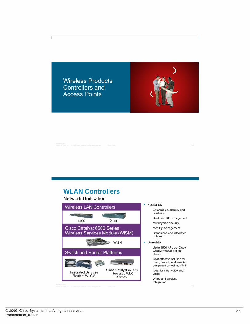
WLAN Controllers
FeaturesEnterprise scalability and reliability
Real-time RF management
Multilayered security
Mobility management
Standalone and integrated options
BenefitsUp to 1500 APs per Cisco Catalyst® 6000 Series chassis
Cost-effective solution for main, branch, and remote campuses as well as SMB
Ideal for data, voice and video
Wired and wireless integration
Wireless LAN Controllers
Cisco Catalyst 6500 Series Wireless Services Module (WiSM)
Switch and Router Platforms
4400 21xx
WiSM
Cisco Catalyst 3750G Integrated WLC
SwitchIntegrated Services
Routers WLCM
Network Unification

© 2006, Cisco Systems, Inc. All rights reserved.Presentation_ID.scr
34
© 2008 Cisco Systems, Inc. All rights reserved. Cisco Public 67BRKAGG-101014589_04_2008_c1
WLAN Access Points
FeaturesIndustry’s best range and throughput
Enterprise-class security
Only 802.11n Draft 2 support with PoE
Simultaneous air monitoring and traffic delivery
Wide-area networking for outdoor areas
BenefitsZero-touch management
No dedicated air monitors
Supports all deployment scenarios (indoor and outdoor)
From secure coverage to advanced services
Indoor Access Points
Indoor Rugged Access Points
Outdoor Access Points/Bridges
Access Points
1130AG 1121BG
1240AG
1230AG1250 ABGN
1510 1400 13001520
© 2008 Cisco Systems, Inc. All rights reserved. Cisco Public 68BRKAGG-101014589_04_2008_c1
Configuration Examples

© 2006, Cisco Systems, Inc. All rights reserved.Presentation_ID.scr
35
© 2008 Cisco Systems, Inc. All rights reserved. Cisco Public 69BRKAGG-101014589_04_2008_c1
Interfaces—Static
ManagementCisco wireless uses the management interface as the default for in-band management of the Cisco Wireless Controller and connectivity to enterprise services, such as AAA
AP-ManagerCisco wireless uses the AP-Manager interface as the source IP address for communications from the Cisco Wireless Controller to Cisco APs; Cisco wireless uses AP-Manager interface for Layer 3 communications between controllers and APs
Service-PortThe Service-Port interface associated only with the service port on the Cisco Wireless Controller front panel is a 10/100Base-T Ethernet port dedicated to Cisco Wireless Controller service for out-of-band management in the event of network failure
VirtualVirtual interface is used when supporting the following features: mobility management, DHCP relay, Layer 3 security
© 2008 Cisco Systems, Inc. All rights reserved. Cisco Public 70BRKAGG-101014589_04_2008_c1
Interface—Dynamic
Dynamic interfaces are generally designed for WLAN client data and provide support for multiple VLAN instances
Dynamic interfaces are manually configured by the administrator
© 2006, Cisco Systems, Inc. All rights reserved.Presentation_ID.scr
36
© 2008 Cisco Systems, Inc. All rights reserved. Cisco Public 71BRKAGG-101014589_04_2008_c1
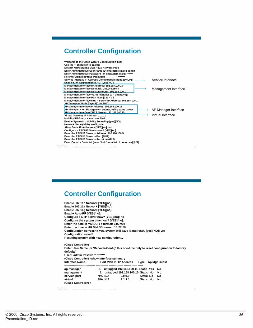
Controller ConfigurationWelcome to the Cisco Wizard Configuration ToolUse the '-' character to backupSystem Name [Cisco_36:d7:83]: Networkers08Enter Administrative User Name (24 characters max): adminEnter Administrative Password (24 characters max): *******Re-enter Administrative Password : *******Service Interface IP Address Configuration [none][DHCP]: Enable Link Aggregation (LAG) [yes][NO]: Management Interface IP Address: 192.168.100.10Management Interface Netmask: 255.255.255.0Management Interface Default Router: 192.168.100.1Management Interface VLAN Identifier (0 = untagged): Management Interface Port Num [1 to 4]: 1Management Interface DHCP Server IP Address: 192.168.100.1 AP Transport Mode [layer2][LAYER3]: AP Manager Interface IP Address: 192.168.100.11 AP-Manager is on Management subnet, using same values AP Manager Interface DHCP Server (192.168.100.1): Virtual Gateway IP Address: 1.1.1.1Mobility/RF Group Name: mobile-1 Enable Symmetric Mobility Tunneling [yes][NO]: Network Name (SSID): nw08_wlanAllow Static IP Addresses [YES][no]: noConfigure a RADIUS Server now? [YES][no]: Enter the RADIUS Server's Address: 192.168.100.5Enter the RADIUS Server's Port [1812]: Enter the RADIUS Server's Secret: test1234Enter Country Code list (enter 'help' for a list of countries) [US]:
Management Interface
AP Manager Interface
Service Interface
Virtual Interface
© 2008 Cisco Systems, Inc. All rights reserved. Cisco Public 72BRKAGG-101014589_04_2008_c1
Controller ConfigurationEnable 802.11b Network [YES][no]: Enable 802.11a Network [YES][no]: Enable 802.11g Network [YES][no]: Enable Auto-RF [YES][no]: Configure a NTP server now? [YES][no]: noConfigure the system time now? [YES][no]: Enter the date in MM/DD/YY format: 04/27/08Enter the time in HH:MM:SS format: 18:27:50Configuration correct? If yes, system will save it and reset. [yes][NO]: yesConfiguration saved!Resetting system with new configuration...
(Cisco Controller) Enter User Name (or 'Recover-Config' this one-time only to reset configuration to factory defaults)User: admin Password:******* (Cisco Controller) >show interface summary Interface Name Port Vlan Id IP Address Type Ap Mgr Guest -------------------------------- ---- -------- --------------- ------- ------ -----ap-manager 1 untagged 192.168.100.11 Static Yes No management 1 untagged 192.168.100.10 Static No No service-port N/A N/A 0.0.0.0 Static No No virtual N/A N/A 1.1.1.1 Static No No (Cisco Controller) >

© 2006, Cisco Systems, Inc. All rights reserved.Presentation_ID.scr
37
© 2008 Cisco Systems, Inc. All rights reserved. Cisco Public 73BRKAGG-101014589_04_2008_c1
Switch Configuration to Be Addedinterface GigabitEthernet x/yswitchportswitchport trunk encapsulation dot1qswitchport trunk native vlan XXswitchport mode trunkno ip addressspanning-tree portfast
© 2008 Cisco Systems, Inc. All rights reserved. Cisco Public 74BRKAGG-101014589_04_2008_c1
References
Understanding the Lightweight Access Point Protocol (LWAPP)http://www.cisco.com/en/US/prod/collateral/wireless/ps5678/ps6306/prod_white_paper0900aecd802c18ee_ns337_Networking_Solutions_White_Paper.html
Deploying Cisco 440X Series Wireless LAN Controllershttp://www.cisco.com/en/US/docs/wireless/technology/controller/deployment/guide/dep.html
Wireless LAN Controller and Lightweight Access Point Basic Configuration
http://www.cisco.com/en/US/products/hw/wireless/ps430/products_configuration_example09186a0080665cdf.shtml
Cisco Wireless Control System (WCS)http://www.cisco.com/en/US/prod/collateral/wireless/ps5755/ps6301/ps6305/product_data_sheet0900aecd802570d0.html
Cisco Wireless Product Overviewhttp://www.cisco.com/en/US/products/hw/wireless/index.html
© 2006, Cisco Systems, Inc. All rights reserved.Presentation_ID.scr
38
© 2008 Cisco Systems, Inc. All rights reserved. Cisco Public 75BRKAGG-101014589_04_2008_c1
Recommended Reading
Continue your Cisco Live learning experience with further reading from Cisco Press
Check the Recommended Reading flyer for suggested books
Available Onsite at the Cisco Company Store
© 2008 Cisco Systems, Inc. All rights reserved. Cisco Public 76BRKAGG-101014589_04_2008_c1
Complete Your Online Session Evaluation
Give us your feedback and you could win fabulous prizes. Winners announced daily.
Receive 20 Passport points for each session evaluation you complete.
Complete your session evaluation online now (open a browser through our wireless network to access our portal) or visit one of the Internet stations throughout the Convention Center.
Don’t forget to activate your Cisco Live virtual account for access to all session material on-demand and return for our live virtual event in October 2008.
Go to the Collaboration Zone in World of Solutions or visit www.cisco-live.com.

© 2006, Cisco Systems, Inc. All rights reserved.Presentation_ID.scr
39
© 2008 Cisco Systems, Inc. All rights reserved. Cisco Public 77BRKAGG-101014589_04_2008_c1