introduction to high-speed infiniband interconnect • industry standard defined by the infiniband...
TRANSCRIPT

Introduction to
High-Speed InfiniBand Interconnect
2
• Industry standard defined by the InfiniBand Trade Association
– Originated in 1999
• InfiniBand™ specification defines an input/output architecture used to interconnect
servers, communications infrastructure equipment, storage and embedded systems
• InfiniBand is a pervasive, low-latency, high-bandwidth interconnect which requires low
processing overhead and is ideal to carry multiple traffic types (clustering,
communications, storage, management) over a single connection.
• As a mature and field-proven technology, InfiniBand is used in thousands of data
centers, high-performance compute clusters and embedded applications that scale from
small scale to large scale
What is InfiniBand?
Source: InfiniBand® Trade Association (IBTA) www.infinibandta.org
3
The InfiniBand Architecture
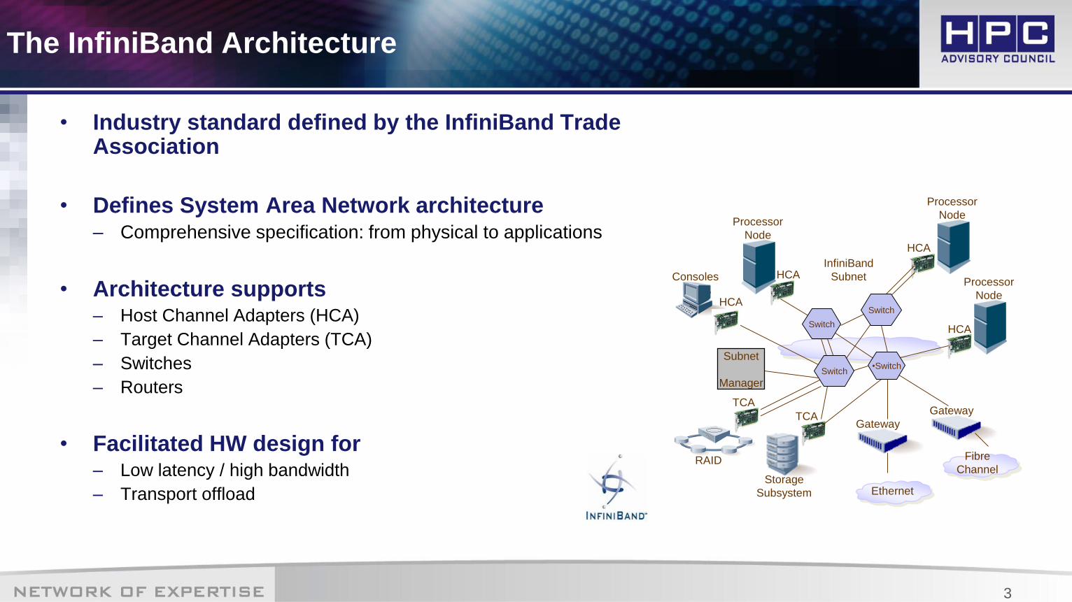
• Industry standard defined by the InfiniBand Trade Association
• Defines System Area Network architecture– Comprehensive specification: from physical to applications
• Architecture supports– Host Channel Adapters (HCA)
– Target Channel Adapters (TCA)
– Switches
– Routers
• Facilitated HW design for – Low latency / high bandwidth
– Transport offload
Processor
Node
InfiniBand
Subnet
Gateway
HCA
Processor
Node
Processor
Node
HCA
HCA
TCA
Storage
Subsystem
Consoles
TCA
RAID
Ethernet
Gateway
Fibre
Channel
HCA
Subnet
Manager
•Switch
Switch
Switch
Switch
4
InfiniBand Highlights
• Serial High Bandwidth Links
– SDR: 10Gb/s
– DDR: 20Gb/s
– QDR: 40Gb/s
– FDR: 56Gb/s
– EDR: 100Gb/s
– HDR: 200Gb/s
• Ultra low latency
– Under 1 us application to application
• Reliable, lossless, self-managing fabric
– Link level flow control
– Congestion control to prevent HOL blocking
• Full CPU Offload
– Hardware Based Reliable Transport Protocol
– Kernel Bypass (User level applications get direct access to
hardware)
• Memory exposed to remote node access
– RDMA-read and RDMA-write
– Atomic operations
• Quality Of Service
– Independent I/O channels at the adapter level
– Virtual Lanes at the link level
• Cluster Scalability/flexibility
– Up to 48K nodes in subnet, up to 2^128 in network
– Parallel routes between end nodes
– Multiple cluster topologies possible
• Simplified Cluster Management
– Centralized route manager
– In-band diagnostics and upgrades

5
InfiniBand Network Stack
User code
Kernel code
Hardware
InfiniBand
node
InfiniBand
Switch
Legacy
node
Application
Network
Layer
Link
Layer
Physical
Layer
Transport
Layer
Network
Layer
Link
Layer
Physical
Layer
Packet relayP
HY
Packet relay
PH
YP
HY
Lin
k
PH
YL
ink
Router
Buffer
BufferBuffer
Transport
Layer
Application

6
InfiniBand Components Overview
• Host Channel Adapter (HCA)
– Device that terminates an IB link and executes transport-level functions and support the verbs interface
• Switch
– A device that routes packets from one link to another of the same IB Subnet
• Router
– A device that transports packets between IBA subnets
• Bridge
– InfiniBand to Ethernet

7
Physical Layer – Link Rate
• InfiniBand uses serial stream of bits for data transfer
• Link width– 1x – One differential pair per Tx/Rx
– 4x – Four differential pairs per Tx/Rx
– 12x - Twelve differential pairs per Tx and per Rx
• Link Speed– Single Data Rate (SDR) - 2.5Gb/s per lane (10Gb/s for 4x)
– Double Data Rate (DDR) - 5Gb/s per lane (20Gb/s for 4x)
– Quad Data Rate (QDR) - 10Gb/s per lane (40Gb/s for 4x)
– Fourteen Data Rate (FDR) - 14Gb/s per lane (56Gb/s for 4x)
– Enhanced Data rate (EDR) - 25Gb/s per lane (100Gb/s for 4x)
• Link rate– Multiplication of the link width and link speed
– Most common shipping today is 4x ports
8
Physical Layer – Cables
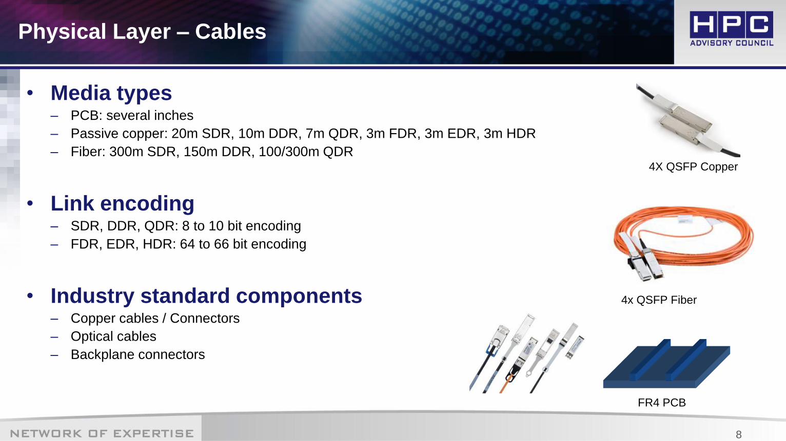
• Media types– PCB: several inches
– Passive copper: 20m SDR, 10m DDR, 7m QDR, 3m FDR, 3m EDR, 3m HDR
– Fiber: 300m SDR, 150m DDR, 100/300m QDR
• Link encoding– SDR, DDR, QDR: 8 to 10 bit encoding
– FDR, EDR, HDR: 64 to 66 bit encoding
• Industry standard components– Copper cables / Connectors
– Optical cables
– Backplane connectors
4X QSFP Copper
4x QSFP Fiber
FR4 PCB
9
Arbitration
De-
muxMux
Link
Control
Packets
Credits
Returned
Link Control
Receive
BuffersPackets
Transmitted
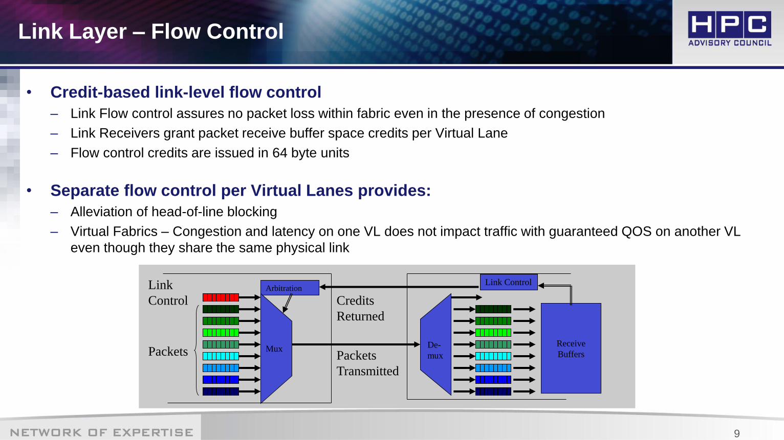
Link Layer – Flow Control
• Credit-based link-level flow control
– Link Flow control assures no packet loss within fabric even in the presence of congestion
– Link Receivers grant packet receive buffer space credits per Virtual Lane
– Flow control credits are issued in 64 byte units
• Separate flow control per Virtual Lanes provides:
– Alleviation of head-of-line blocking
– Virtual Fabrics – Congestion and latency on one VL does not impact traffic with guaranteed QOS on another VL
even though they share the same physical link

10
Remote QPLocal QP
Transport Layer – Using Queue Pairs
• QPs are in pairs (Send/Receive)
• Work Queue is the consumer/producer interface to the fabric
• The Consumer/producer initiates a Work Queue Element (WQE)
• The Channel Adapter executes the work request
• The Channel Adapter notifies on completion or errors by writing a Completion Queue
Element (CQE) to a Completion Queue (CQ)
Transmit
Receive
Receive
TransmitWQE
11
Transport Layer – Types Transfer Operations
• SEND
– Read message from HCA local system memory
– Transfers data to Responder HCA Receive Queue logic
– Does not specify where the data will be written in remote memory
– Immediate Data option available
• RDMA Read
– Responder HCA reads its local memory and returns it to the Requesting HCA
– Requires remote memory access rights, memory start address, message length
• RDMA Write
– Requester HCA sends data to be written into the Responder HCA’s system memory
– Requires remote memory access rights, memory start address, message length

12
Management Model
• IBA management defines a common management infrastructure
• Subnet Management
– Provides methods for a subnet manager to discover and configure IBA devices
– Manage the fabric
• General management services
– Subnet administration - provides nodes with information gathered by the SM
– Provides a registrar for nodes to register general services they provide
– Communication establishment and connection management between end nodes
– Performance management
• Monitors and reports well-defined performance counters
– And more…
13
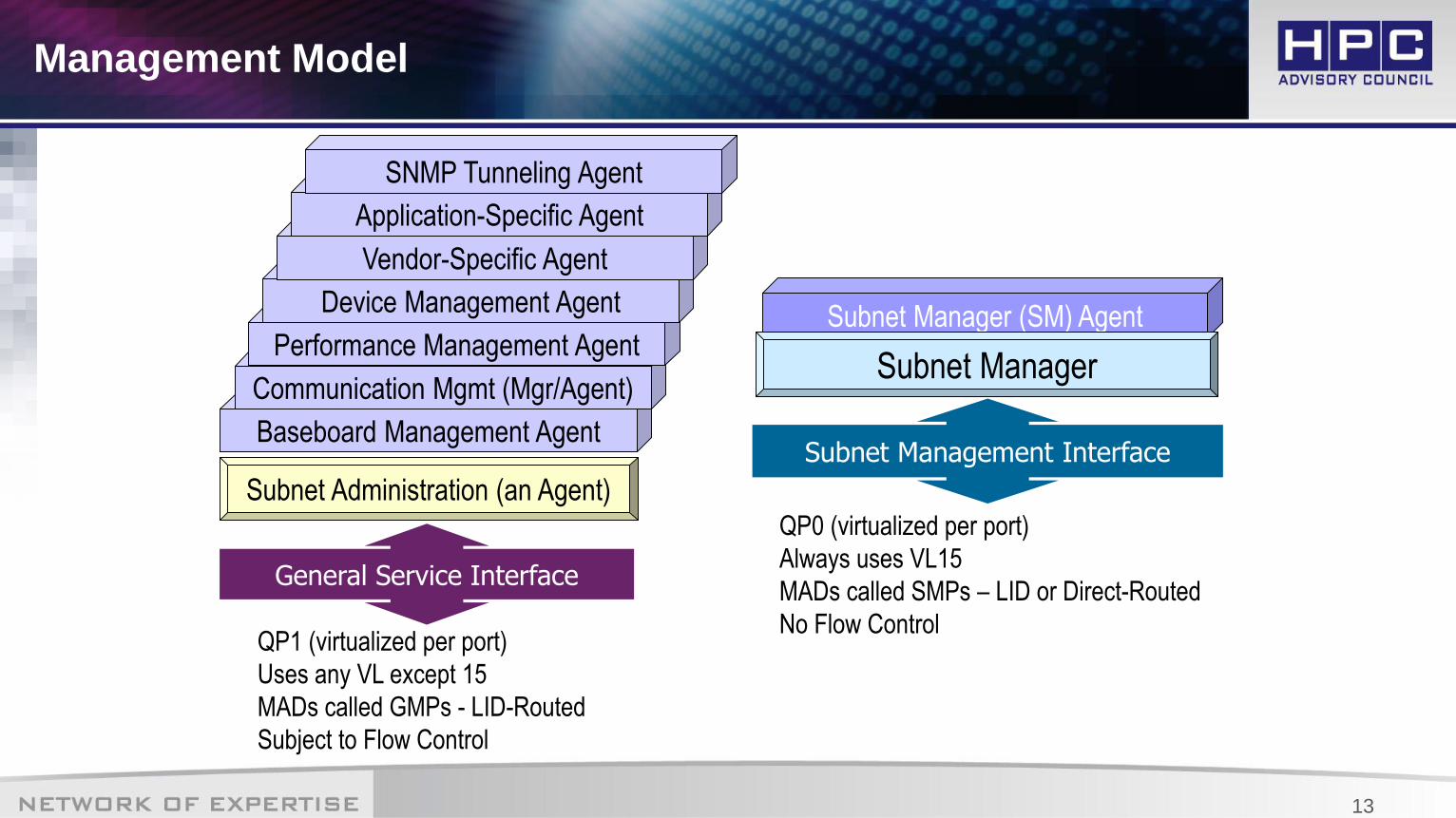
Management Model
QP1 (virtualized per port)
Uses any VL except 15
MADs called GMPs - LID-Routed
Subject to Flow Control
Baseboard Management Agent
Communication Mgmt (Mgr/Agent)
Performance Management Agent
Device Management Agent
Vendor-Specific Agent
Application-Specific Agent
SNMP Tunneling Agent
Subnet Administration (an Agent)
General Service Interface
Subnet Manager (SM) Agent
Subnet Manager
Subnet Management Interface
QP0 (virtualized per port)
Always uses VL15
MADs called SMPs – LID or Direct-Routed
No Flow Control
14
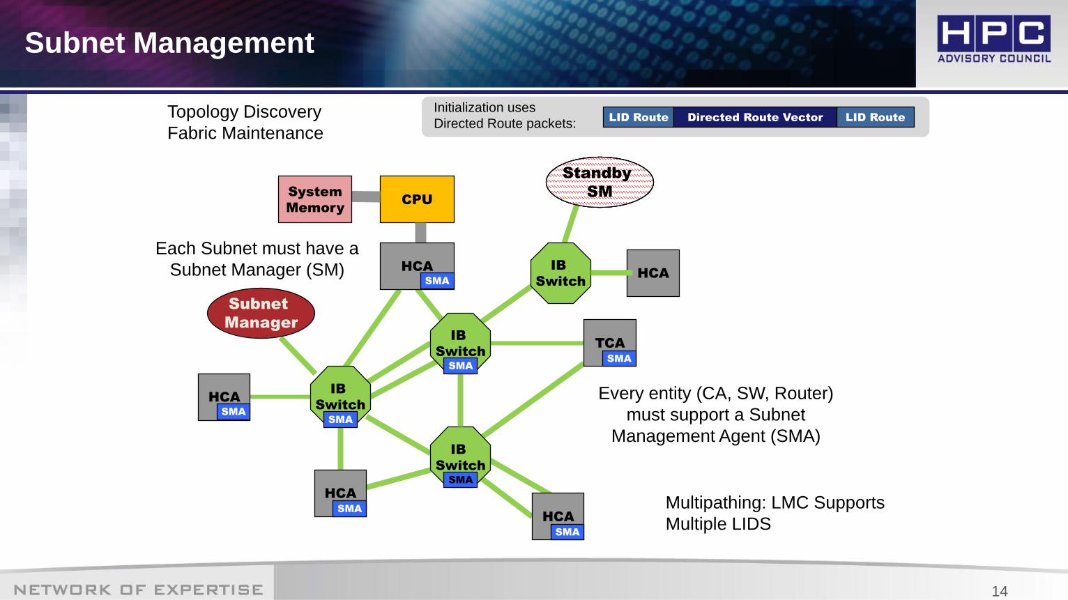
Subnet Management
CPU
HCA
System
Memory
HCA
IB
Switch
IB
Switch
HCA
IB
Switch
TCA
HCA
Subnet
Manager
Each Subnet must have a
Subnet Manager (SM)
SMA
SMA
SMA
SMA
SMA
SMA
SMA
SMA
Every entity (CA, SW, Router)
must support a Subnet
Management Agent (SMA)
Subnet
Manager
HCAIB
Switch
Standby
SM
Standby
SM
Standby
SM
Topology Discovery
Fabric MaintenanceLID Route Directed Route Vector LID Route
Initialization uses
Directed Route packets:
Multipathing: LMC Supports
Multiple LIDS
15
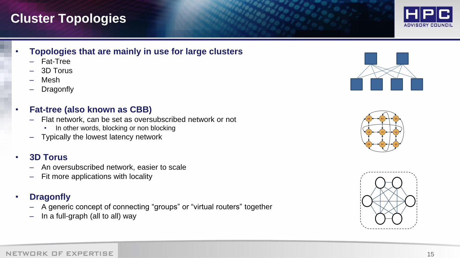
Cluster Topologies
• Topologies that are mainly in use for large clusters– Fat-Tree
– 3D Torus
– Mesh
– Dragonfly
• Fat-tree (also known as CBB)– Flat network, can be set as oversubscribed network or not
• In other words, blocking or non blocking
– Typically the lowest latency network
• 3D Torus– An oversubscribed network, easier to scale
– Fit more applications with locality
• Dragonfly– A generic concept of connecting “groups” or “virtual routers” together
– In a full-graph (all to all) way
0,0
1,0
0,1
1,1
2,0 2,1
0,2
1,2
2,2
16
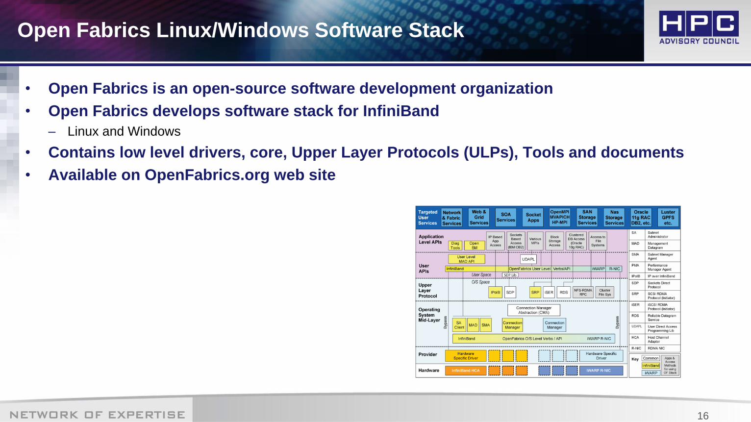
Open Fabrics Linux/Windows Software Stack
• Open Fabrics is an open-source software development organization
• Open Fabrics develops software stack for InfiniBand
– Linux and Windows
• Contains low level drivers, core, Upper Layer Protocols (ULPs), Tools and documents
• Available on OpenFabrics.org web site

17
• IPoIB – IP over IB (TCP/UDP over InfiniBand)
• EoIB – Ethernet over IB
• RDS – Reliable Datagram Sockets
• MPI – Message Passing Interface
• iSER – iSCSI for InfiniBand
• SRP – SCSI RDMA Protocol
• uDAPL – User Direct Access Programming Library
• NetworkDirect (Windows only)
Software Stack – Upper Layer protocols Examples
All trademarks are property of their respective owners. All information is provided “As-Is” without any kind of warranty. The HPC Advisory Council makes no representation to the accuracy and completeness of the information
contained herein. HPC Advisory Council undertakes no duty and assumes no obligation to update or correct any information presented herein
Thank Youwww.hpcadvisorycouncil.com