introduction to ls-dynaftp.lstc.com/anonymous/outgoing/lsprepost/training/intro/...table of contents...
TRANSCRIPT

Introduction to LS-PrePost Quanqing Yan, Philip Ho, LSTC 2018
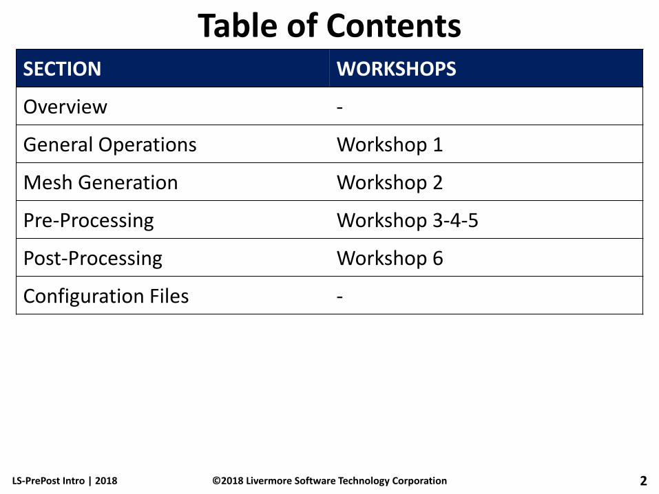
Table of Contents
LS-PrePost Intro | 2018
SECTION WORKSHOPS
Overview -
General Operations Workshop 1
Mesh Generation Workshop 2
Pre-Processing Workshop 3-4-5
Post-Processing Workshop 6
Configuration Files -
2 ©2018 Livermore Software Technology Corporation

Overview
LS-PrePost Intro | 2018 3 ©2018 Livermore Software Technology Corporation

About LS-PrePost
LS-PrePost is an advanced pre and post-processor designed specifically for LS-DYNA
LS-PrePost is developed for Windows and Linux
LS-PrePost is Free
Core Functionality
• Full support of LS-DYNA keyword files
• Full support of LS-DYNA results files
• Robust handling of geometry data (new CAD engine)
• Pre-processing (meshing, model clean-up, entity creation)
• Post-processing (animation, fringe plotting, curve plotting)
LS-PrePost Intro | 2018 4 ©2018 Livermore Software Technology Corporation

Online Resources
Official Website
• http://www.lstc.com/lspp
User Group
• http://groups.google.com/group/ls-prepost
Latest Release Version:
• http://ftp.lstc.com/anonymous/outgoing/lsprepost/4.5/
• ftp://ftp.lstc.com/outgoing/lsprepost/4.5/
Beta Version: • http://ftp.lstc.com/anonymous/outgoing/lsprepost/dev
Training notes: • ftp://ftp.lstc.com/outgoing/qyan/Class
LS-PrePost Intro | 2018 5 ©2018 Livermore Software Technology Corporation
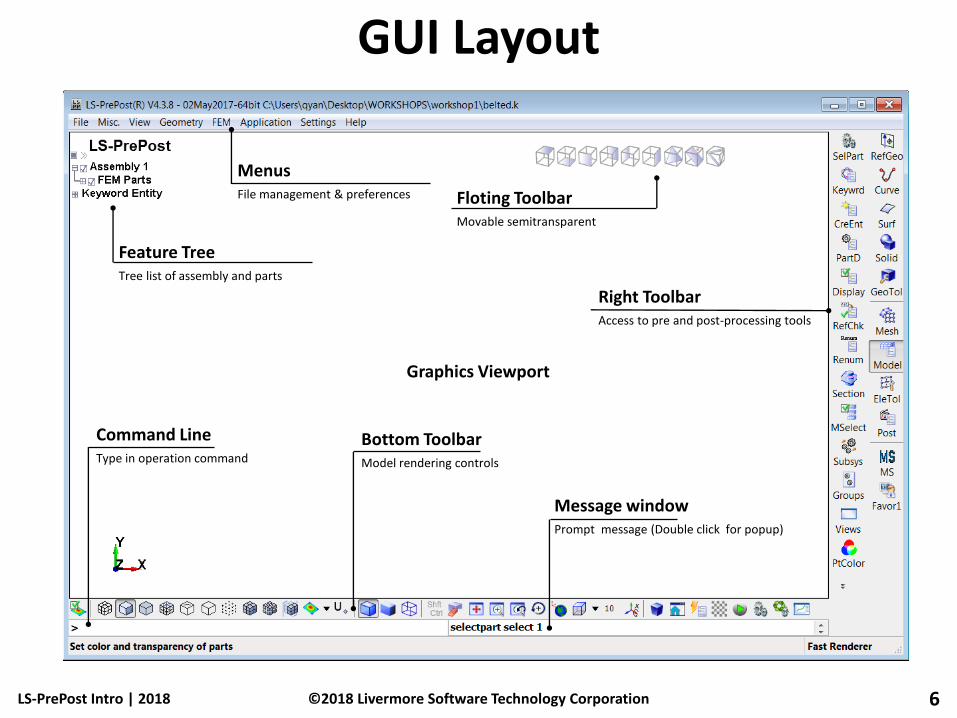
Menus File management & preferences
GUI Layout
LS-PrePost Intro | 2018 6
Command Line Type in operation command
Bottom Toolbar Model rendering controls
Right Toolbar Access to pre and post-processing tools
Graphics Viewport
©2018 Livermore Software Technology Corporation
Message window Prompt message (Double click for popup)
Floting Toolbar Movable semitransparent
Feature Tree Tree list of assembly and parts

Input / Output
Input (partial list)
• FEM: LS-DYNA Keyword, Nastran, I-DEAS Universal, PAM-CRASH, RADIOSS, ABAQUS
• CAD: IGES, STEP
• ASCII: glstat, matsum, etc…
• Binary: d3plot, binout, etc…
Output (partial list)
• FEM: LS-DYNA Keyword, Nastran, STL
• Image: PNG, TIFF, BMP, GIF, JPG, PostScript
• Movie: AVI, MPEG, Animated GIF, JPEG
• XY Data: CRV, CSV, XML
• Other: Post.db, Project File
LS-PrePost Intro | 2018 7 ©2018 Livermore Software Technology Corporation

Mouse and Keyboard
Dynamic Model Operation
• Rotate: Shift + Left-click
• Translate: Shift + Middle-click
• Zoom: Shift + Right-click/Scroll-wheel
(Using Ctrl instead of Shift for edge mode)
Graphics Selection
• Pick (single): Left Click
• Area (rectangle): Left-click + Drag
• Poly (polygon): Left-click at corners / Right-click to finish
List Selection
• Multi-Select: Left-click + Drag / Ctrl + Left-click
Mouse over controls for status bar help comments
LS-PrePost Intro | 2018 8 ©2018 Livermore Software Technology Corporation

File Menu New – Launch a new session of LS-PrePost, all model/data will be
closed (only in version 4.0 and later)
Open – Open file (new model created for each file opened)
Import – Import file (adds keyword data to current model)
Recent – Open recent files (stored in /user/.lspp_recent)
Save – Over-write current Keyword or Project file
Save As – Save any of the following file formats using advanced options: Keyword, Active Keyword (visible data), Project, Post.db (condensed d3plot data), Geometry, Keyword and Project (using same file name)
Update – Load new d3plots for run in progress
Run LS-DYNA – pop up LS-DYNA job submission dialog, currently only limited to the same local machine LS-PrePost is running
Print... – Launch printing interface (send to printer or image file)
Movie... – Launch movie generation interface
Exit – Exit LS-PrePost
Save and Exit – Save data to current file and exit LS-PrePost
LS-PrePost Intro | 2018 9 ©2018 Livermore Software Technology Corporation

Miscellanies Menu View Model Info – Launch model information interface
View Memory Info – Launch memory usage interface
View Message Info – Launch keyword reader message interface
Display Ruler – Launch ruler interface
Set Keyword Title – Launch title interface
Swap Byte On Title – Swap byte order for title
Start Recording Commands – Start/stop recording macro commands
Launch Macro Interface – Launch Macro interface
Manage Command File – Launch command file interface
Execute System Call – Launch system call interface
Keyword File Separate – Separate a single keyword file into multiple files based on *KEYWORD title
LS-PrePost Intro | 2018 10 ©2018 Livermore Software Technology Corporation
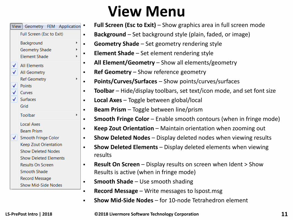
View Menu Full Screen (Esc to Exit) – Show graphics area in full screen mode
Background – Set background style (plain, faded, or image)
Geometry Shade – Set geometry rendering style
Element Shade – Set element rendering style
All Element/Geometry – Show all elements/geometry
Ref Geometry – Show reference geometry
Points/Curves/Surfaces – Show points/curves/surfaces
Toolbar – Hide/display toolbars, set text/icon mode, and set font size
Local Axes – Toggle between global/local
Beam Prism – Toggle between line/prism
Smooth Fringe Color – Enable smooth contours (when in fringe mode)
Keep Zout Orientation – Maintain orientation when zooming out
Show Deleted Nodes – Display deleted nodes when viewing results
Show Deleted Elements – Display deleted elements when viewing results
Result On Screen – Display results on screen when Ident > Show Results is active (when in fringe mode)
Smooth Shade – Use smooth shading
Record Message – Write messages to lspost.msg
Show Mid-Side Nodes – for 10-node Tetrahedron element
LS-PrePost Intro | 2018 11 ©2018 Livermore Software Technology Corporation

Geometry Menu Reference Geometry – Access tools for creating and editing
reference geometry (Axis, Plane, Coordinate System, and Point)
Curve – Access tools for creating and editing curves (Point, Line, Circle, Circular Arc, Ellipse, Elliptical Arc, BSpline Curve, Helix, Composite Curve, Break Curve, Merge Curve, Bridge Edge, Smooth Curve, Middle Curve, Morphing Curve, Fillet Curve)
Surface – Access tools for creating and editing surfaces (Plane, Cylinder, Cone, Sphere, Torus, Fill Plane, Extrude, Revolve, Sweep, Loft, N-Side Surface, Patch Surface, Bridge Two Faces, Combine Faces, Fit From Points/Mesh, Middle Surface, Surface Morphing)
Solid – Access tools for creating and editing solids (Box, Cylinder, Cone, Sphere, Torus, Extrude, Revolve, Sweep, Loft, Fillet, Chamfer, Draft, Thicken, Wedge, Boolean)
Geometry Tools – Access other geometry tools (Delete Face, Extend Curve, Extend Face, Intersection, Offset, Project, Replace Face, Stitch Faces, Trim Transform, Copy Entity, Management, Heal, Topology Simplify, Measure)
LS-PrePost Intro | 2018 12 ©2018 Livermore Software Technology Corporation

FEM Menu Element and Mesh – Access mesh creation tools (Shape
Mesher, Auto Mesher, Solid Mesher, Block Mesher, N-Line Mesher, Tetrahedral Mesher, Blank Mesher, Element Generation, Node Editing, Element, Editing, Mass Trimming, Spot Welding, SPH Generation)
Model and Part – Access model and part tools (Assembly and Select Part, Keyword Manager, Create Entity, Display Entity, Reference Check, Renumber, Section Plane, Model Selection, Subsystem Manager, Group, View, Part Color, Appearance, Annotation, Split Window, Explode, Lighting Setup)
Element Tools – Access element tools (Identify, Find, Blank, Move or Copy, Offset, Transform, Normals, Detach, Measure, Morph, Smooth, Part Trim, Part Travel)
Post – Access post-processing tools (Fringe Component, Fringe Range, History, XY Plot, ASCII, Binary Output, Follow, Trace, State, Particle, Circle Grid, Chain Model, FLD, Output, Setting, Vector)
Favorites – Customizable toolbar (see Setting → Toolbar Manager)
LS-PrePost Intro | 2018 13 ©2018 Livermore Software Technology Corporation
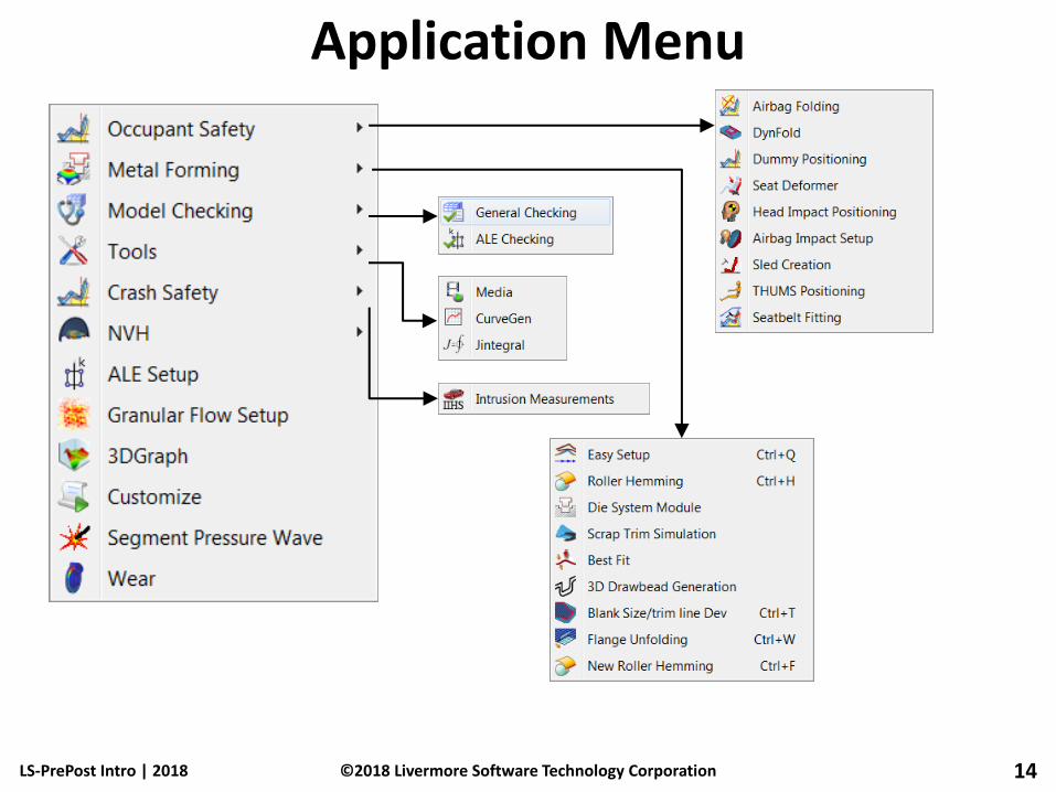
Application Menu
LS-PrePost Intro | 2018 14 ©2018 Livermore Software Technology Corporation
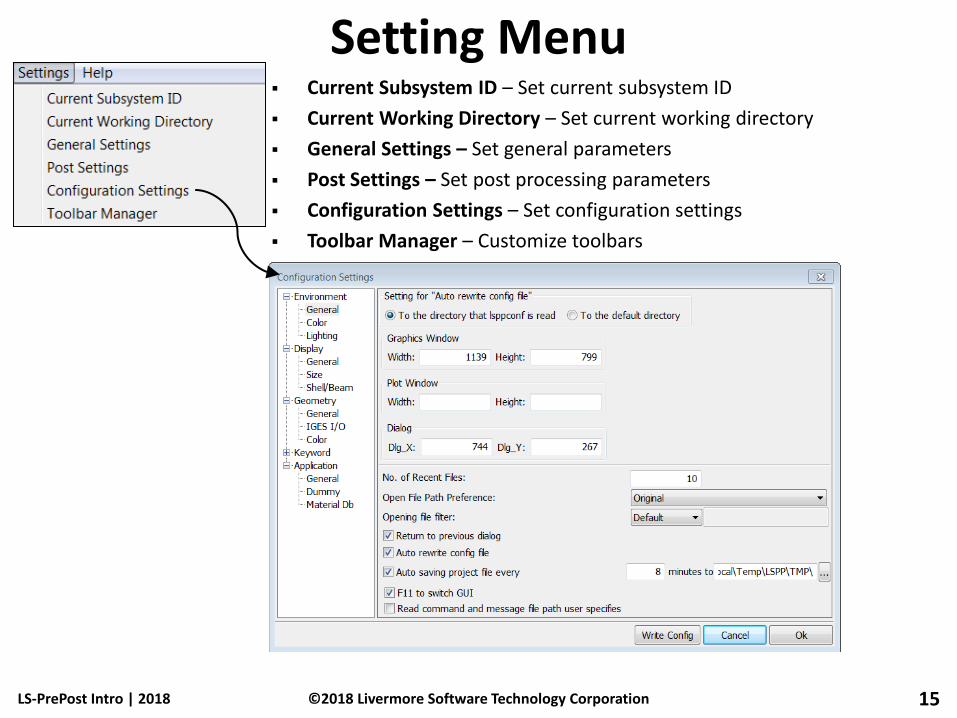
Setting Menu Current Subsystem ID – Set current subsystem ID
Current Working Directory – Set current working directory
General Settings – Set general parameters
Post Settings – Set post processing parameters
Configuration Settings – Set configuration settings
Toolbar Manager – Customize toolbars
LS-PrePost Intro | 2018 15 ©2018 Livermore Software Technology Corporation

Help Menu Document – View LS-PrePost documentation
Tutorial – View LS-PrePost tutorials
Will need to download the Help and Tutorial documents from LSTC’s ftp site the first time these documents are being accessed
Old to New – View mapping between old (v2.4) and new (v3.0+) GUI
Release Notes – View release notes
Check for Update – Check server for newer version of LS-PrePost
About LS-PrePost – View version info
LS-PrePost Intro | 2018 16 ©2018 Livermore Software Technology Corporation

Bottom Toolbar
LS-PrePost Intro | 2018 17
Opti Toggle Title, Legend, Min-Max, Time Stamp, Triad,
Background Color, Mesh Color, Performance Stats on/off,
Feature Tree, ISO View and Animation Play
HidEle Display elements with hidden lines removed
ShaEle Display elements in shaded mode with mesh lines off
VieEle Display elements in plain color mode
WirEle Display elements in wireframe mode
Feat Display elements in feature line mode (default angle=30°)
Edge Display elements in edge line mode
Grid Display each nodal point as a colored pixel
Mesh Toggle element mesh on/off
Shrink Draw elements in shrunken mode (default=0.85)
Section Display section view with plane selected
Frin Toggle Fringe/Line-contours/Iso-surfaces
Unref Toggle unreferenced nodes on/off
EdgGeo Display geometry in shaded mode with edges on
ShaGeo Display geometry in shaded mode with edges off
WirGeo Display geometry in wireframe mode
ShfCtr Toggle Off/Shift/Ctrl (for one-handed rotate/pan/zoom)
Clear Clear all picked or highlighted information
AutCen Automatically center model to fit within window
ZoIn Zoom in, click and drag to draw a box
Zout Zoom out to previous zoom position
Pcen Pick node as new center point for model rotation
VCrd View coordinate systems
Top Choose Top, Bottom, Front, Back, Right, or Left view
Angle Left-click to reverse rotation direction
Right-click to modify rotation angle
Rotate Left-click to rotate about axis shown
Right-click to switch rotation axis (X/Y/Z)
Persp Toggle Parallel/Perspective view mode
Home Restore default view and fit model
ActAll Restore all entities to be active
BacCol Toggle background color black/white (Plain background mode only)
Anim Display animation controls or start/stop animation
SelPart Launch Assembly and Select Part interface
ResPart Restore the last removed part (Shift+R)
Plot Open XY plot management interface
©2018 Livermore Software Technology Corporation

General Operations
LS-PrePost Intro | 2018 18 ©2018 Livermore Software Technology Corporation

FEM General Selection ID Enter Ids of the entity to be selected into
the text box for highlighting
Type When selecting element, choose element type to be selected
Label selection put a label on the selected entities
Prop Propagate selection (pick seed)
Adap Propagate across adaptive elements
Ang Feature angle for propagation to stop
LS-PrePost Intro | 2018 19
Pick Select a single entity
Area Select using a rectangular window
Poly Select using an irregular polygon
Sel1 Pick 1 entity (only 1 will be in buffer)
Sphe Select entities within a sphere
Box Select entities within a box
Prox Select entities within proximity to a part
Circ Select entities within a circle
Frin Select entities within a fringe plot range
Plan Select entities within a plane
In Select entities inside Area/Poly
Out Select entities outside Area/Poly
Add Add entities to a selection set
Rm Remove entities to a selection set
©2018 Livermore Software Technology Corporation

FEM General Selection
ByNode Select nodes ByElem Select elements ByPart Select parts BySet Set based selection ByEdge Edge based selection ByPath Select first and last along a path BySegm Select segments BySurf Select surface (geometry)
LS-PrePost Intro | 2018 20
Adjacent Select adjacent elements
Attach Select attached elements
Clear Clear selection
Save Save selection to buffer or to file
Load Load selection from buffer or
from file
Deselect Undo last selection
Whole Select all entities in model
Visible Select all visible entities
Reverse Reverse selection
©2018 Livermore Software Technology Corporation

Model → Assembly and Select Part Purpose: turn parts on/off (on=“active”)
Parts listed by PID and name (or element type)
Top drop-down menu selects current model
Parts can be turned on/off by element type
Use General selection to select parts
Active parts can be Saved/Loaded from buffers (via Save button in General selection)
Selected displays active parts only in list
Info button launches Part Information interface for active parts
SortBy button launches Part Sort interface
LS-PrePost Intro | 2018 21 ©2018 Livermore Software Technology Corporation

Model → Assembly and Select Part
LS-PrePost Intro | 2018 22 ©2018 Livermore Software Technology Corporation
Right click on part to show
the part information and
statistics
Keep mouse pressed and
move to other part to show
information dynamically
Keyword data gives more
information than post-
processing data

Model->Select Part->SortBy
LS-PrePost Intro | 2018 23 ©2018 Livermore Software Technology Corporation
Options to select info
to be tabulated
Each header can be
clicked to sort the IDs
of that column
Highlighted parts can
be set as active part in
the graphics rendering

Element Tools → Blank Purpose: temporarily hide or “mask” elements
Uses General Selection interface
Entity types: • Node, Element, CNRB, Curve, Surface, Particle
Element types: • Shell, Solid, Beam, TShell, SPH, Mass, Discrete, Seatbelt,
Inertia, Nurbs, DiscSph, Any element
UnBlank Part – click to restore partially hidden parts
Auto-Apply – blank automatically (no need to click Apply button)
Auto-Update – update display of solid surfaces and edges automatically (no need to click Update Surf or Update Edge)
LS-PrePost Intro | 2018 24 ©2018 Livermore Software Technology Corporation

Model → Views Purpose: create views (based on color, appearance,
orientation, and active parts)
Create – create a new view
Select – load the selected view
Delete – delete the selected view
Save – save views to a binary file
Load – load views from file
LS-PrePost Intro | 2018 25 ©2018 Livermore Software Technology Corporation

Model → Appearance Purpose: modify the appearance of parts
Parts can be selected by Single/Area/Polygon
Each selected part will have the selected rendering options applied
Thick – draw shells with true thickness
Sphere – draw solid part nodes as spheres (for EFG)
AllVis – selected rendering options are applied to all active parts
Render buttons are disabled while using Appear interface
LS-PrePost Intro | 2018 26 ©2018 Livermore Software Technology Corporation

Model → Part Color Purpose: modify part color and transparency
Set/Show colors for parts or other entities (background, text, mesh, labels)
Sky (top), Middle, Ground (bottom) refer to background color (when View > Background > Tri Fade is selected)
Select color from palette or form new color using RBG
Editmap – to assign new color to the color map
Fringe colors can also be changed – select a fringe color, then after the color selection, click Fringe button.
Amap – apply the current color map to part drawing
Rstp – restore transparency of all parts to opaque
LS-PrePost Intro | 2018 27 ©2018 Livermore Software Technology Corporation

Model → Part Color Smap – save the current color map to a file
Lmap – load color map from a previous saved file
Transparency – draw part in transparent mode, transparency factor:
0.0 fully opaque (once is set to 0.0, need to click part again to turn it into transparent)
1.0 totally transparent
Pick toggle – pick a part to toggle it from opaque to transparent and vice versa
Pick through – pick through a part to set part that is behind this part
LS-PrePost Intro | 2018 28 ©2018 Livermore Software Technology Corporation

Model → Lighting Setup Purpose: adjust model and material lighting
Light – adjust model lights • 2 lights are on by default
Front – position (0.0, 0.0, 1.0)
Back – position (0.0, 0.0, -1.0)
Click the Latitude and Longitude to control the light position
• Up to 8 more can be activated
• The following properties can be adjusted for each
Ambient
Diffuse
Specular
Material – adjust material lighting properties and the Shininess
LS-PrePost Intro | 2018 29 ©2018 Livermore Software Technology Corporation
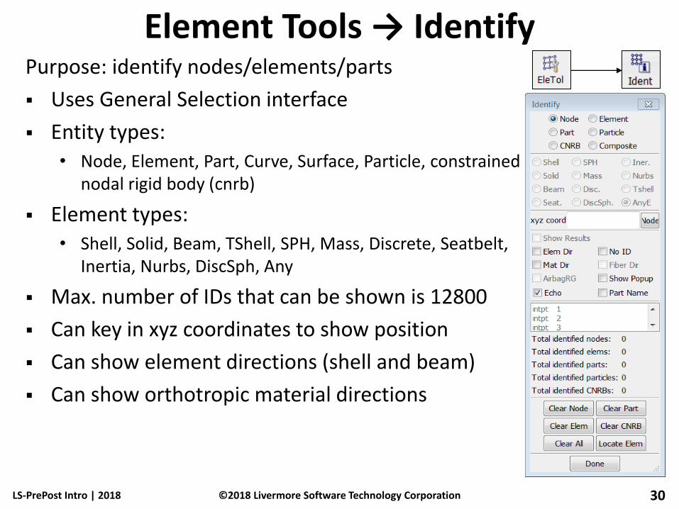
Element Tools → Identify Purpose: identify nodes/elements/parts
Uses General Selection interface
Entity types: • Node, Element, Part, Curve, Surface, Particle, constrained
nodal rigid body (cnrb)
Element types: • Shell, Solid, Beam, TShell, SPH, Mass, Discrete, Seatbelt,
Inertia, Nurbs, DiscSph, Any
Max. number of IDs that can be shown is 12800
Can key in xyz coordinates to show position
Can show element directions (shell and beam)
Can show orthotropic material directions
LS-PrePost Intro | 2018 30 ©2018 Livermore Software Technology Corporation

Element Tools → Identify Purpose: identify nodes/elements/parts
Can show node/element results (after fringing in post-processing)
Can show element results at integration points
To show result on screen, go to pull down menu View, and turn on “Results on Screen”
When identifying a very large no. of nodes or elements, make sure to turn off “Echo” and turn on “No ID”, otherwise will take a long time to come back
LS-PrePost Intro | 2018 31 ©2018 Livermore Software Technology Corporation

Element Tools → Find Purpose: find nodes/elements/parts/Cnrb
Find any element by ID or specified type
Show Only – shows found entity by itself
Highlight – highlights found entity
Neighbors – propagates to neighboring elements
UnblankAll – turns on all elements and parts
UnblankPart – turns on all elements in part that found node/element belongs to
LS-PrePost Intro | 2018 32 ©2018 Livermore Software Technology Corporation

Model → Groups Purpose: create part groups
Groups are automatically generated for all *SET_PART that exist in the model
Create – create a new group from active parts
Select – load the selected group
Add – add a group to the current display
Subtract – subtract a group from the current display
Save – save groups to an ASCII file
Load – load groups from file (Save and Load effective for presentations)
Or, And, Xor – used for Adding groups
Auto Center – automatically center the selected group
LS-PrePost Intro | 2018 33 ©2018 Livermore Software Technology Corporation

Model → Explode Purpose: separate (explode) parts for better
visualization
Factor – scale factor for parts movement
Direction – direction for part movement
All – explode all parts
Part – explode selected parts only
PtGroup – explode a group of parts (defined using Page 1: Group)
LS-PrePost Intro | 2018 34 ©2018 Livermore Software Technology Corporation

Model → Annotation Purpose: annotate Graphics and XY-Plot windows
Position – interactively position text
Arrow – add fixed arrow
Nd Arrow – add arrow tied to node location
Move – move annotations
Text size, color, and orientation can be adjusted
Annotations can be saved to / loaded from a file
LS-PrePost Intro | 2018 35 ©2018 Livermore Software Technology Corporation

Workshop 1 General Operations
LS-PrePost Intro | 2018 36 ©2018 Livermore Software Technology Corporation
Parts on/off
Render buttons (bottom toolbar)
Group, appearance and view
Identify and find
Element blank(mask)
Part color
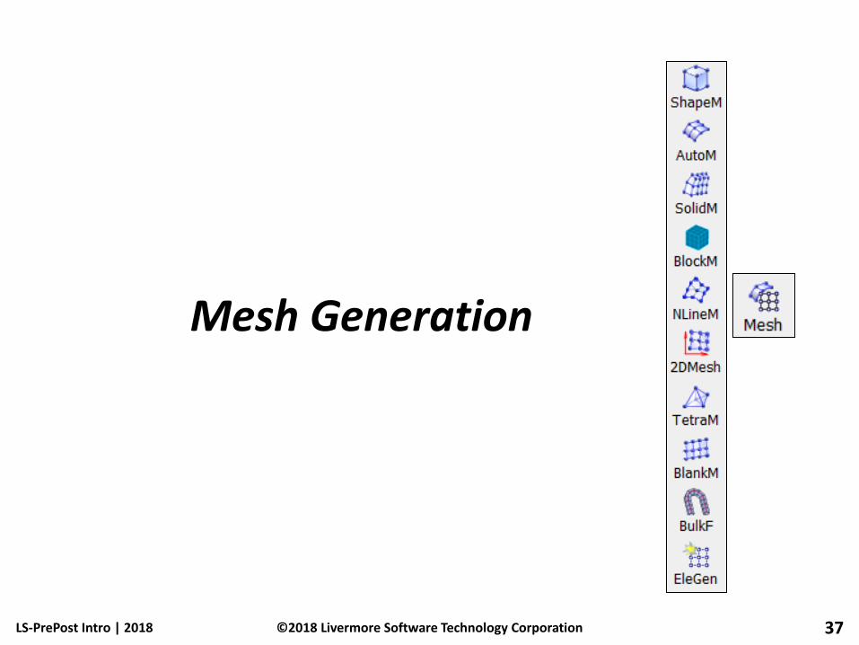
Mesh Generation
LS-PrePost Intro | 2018 37 ©2018 Livermore Software Technology Corporation

Create Position Interface Purpose: define an XYZ location
By picking a position
By picking a node
At an element center
At an edge midpoint
At the average center of nodes or elements
At the center of a circle
New *NODE can be created
LS-PrePost Intro | 2018 38 ©2018 Livermore Software Technology Corporation
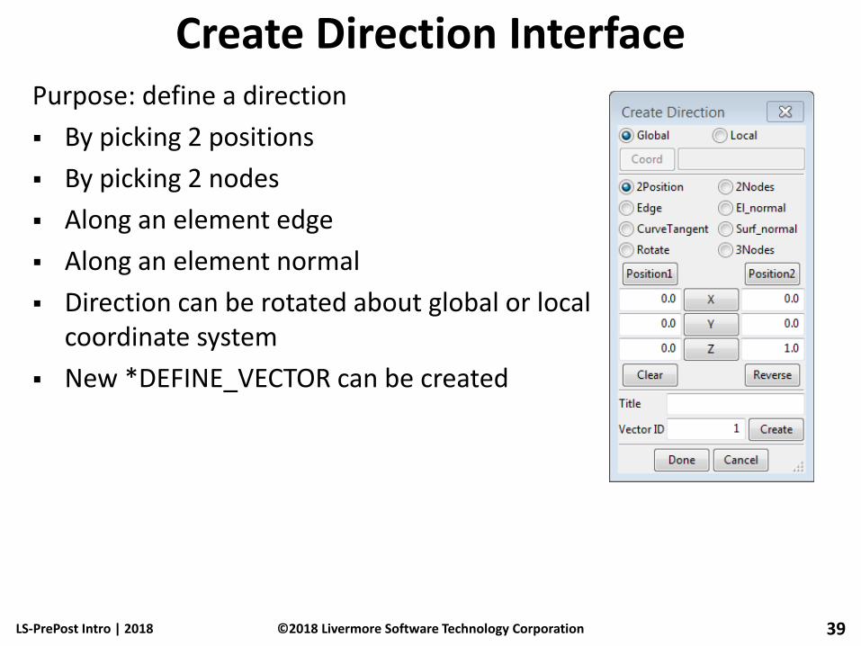
Create Direction Interface Purpose: define a direction
By picking 2 positions
By picking 2 nodes
Along an element edge
Along an element normal
Direction can be rotated about global or local coordinate system
New *DEFINE_VECTOR can be created
LS-PrePost Intro | 2018 39 ©2018 Livermore Software Technology Corporation
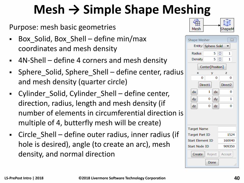
Mesh → Simple Shape Meshing Purpose: mesh basic geometries
Box_Solid, Box_Shell – define min/max coordinates and mesh density
4N-Shell – define 4 corners and mesh density
Sphere_Solid, Sphere_Shell – define center, radius and mesh density (quarter circle)
Cylinder_Solid, Cylinder_Shell – define center, direction, radius, length and mesh density (if number of elements in circumferential direction is multiple of 4, butterfly mesh will be create)
Circle_Shell – define outer radius, inner radius (if hole is desired), angle (to create an arc), mesh density, and normal direction
LS-PrePost Intro | 2018 40 ©2018 Livermore Software Technology Corporation

Mesh → Auto Mesher (Size) Mesh by Size creates uniformly sized elements
Can be mix of quad and tri element or all tri only
Compute button will give rough estimate of element size
Connect Boundary Nodes will connect with the nodes on existing mesh
Mesh Across Suppressed Edges will ignore edges that is suppressed in the geometry Heal->Edge
Mesh by GPart will create separate LS-DYNA part for each geometry part
Ignore Hole Size, hole size smaller than this value will be ignore and be filled with elements
Merge Tolerance controls nodes being merged when close to each other
LS-PrePost Intro | 2018 41 ©2018 Livermore Software Technology Corporation

Mesh → Auto Mesher (Variable size) Mesh by variable size will create mesh that has
smaller elements at high curvature area and larger elements on flat surfaces
It is similar to “By Size” method, in general gives better results
4 parameters control the element size • Max element size
• Min element size
• Max deviation
• Max angle
LS-PrePost Intro | 2018 42 ©2018 Livermore Software Technology Corporation

Mesh → Auto Mesher (Deviation) Mesh by Deviation is for tooling in metal forming
stamping applications
Deviation mode creates small elements on curved surfaces and large elements on flat surfaces
4 parameters control the element size • Max element size
• Min element size
• Max deviation
• Max angle
LS-PrePost Intro | 2018 43 ©2018 Livermore Software Technology Corporation

Mesh → Auto Mesher (Remesh) Remesh mode allows user to remesh
part of the model
Options to delete the original elements and connect to the nodes on the existing mesh
LS-PrePost Intro | 2018 44 ©2018 Livermore Software Technology Corporation

Mesh → N-Line Mesher Purpose: create mesh from 2/3/4 lines
2 Line Shell – create mesh between 2 lines
3 Line Shell – create mesh between 3 lines
4 Line Shell – create mesh between 4 lines • Enter number of elements on each edge
• Or enter element size
• Or use points on lines to create elements
Line Sweep – sweep one line along another line
LS-PrePost Intro | 2018 45 ©2018 Livermore Software Technology Corporation

Mesh → Solid Mesher Solid meshing by blocks
Uses cut & dice method followed by sweeping
LS-PrePost Intro | November , 2012 46 ©2012 Livermore Software Technology Corporation
Define cutting planes on geometry
Cut and trim into small blocks
Sweep block faces to form hex elements

Mesh → Tetrahedron Mesher Purpose: create 4-node solid elements
(tetrahedron) inside an enclosed shell volume
Pick Skin Parts – shell parts that form a water tight enclosure, multiple parts are allowed as long as each part form the enclosure
Requirement: skin normal must be aligned
Skin can be re-meshed to give better solid tetrahedron mesh
Pick Skin Geometry – surface geometry can be used instead of shell part, LSPP will first create shell mesh internally, element size is needed for shell meshing
10-node tets can also be created
Created Solid mesh can be translated in space
LS-PrePost Intro | 2018 47 ©2018 Livermore Software Technology Corporation
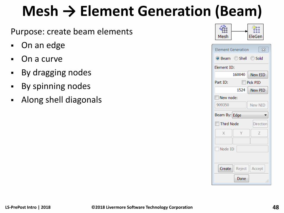
Mesh → Element Generation (Beam) Purpose: create beam elements
On an edge
On a curve
By dragging nodes
By spinning nodes
Along shell diagonals
LS-PrePost Intro | 2018 48 ©2018 Livermore Software Technology Corporation
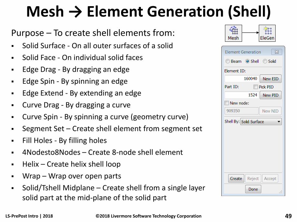
Mesh → Element Generation (Shell) Purpose – To create shell elements from: Solid Surface - On all outer surfaces of a solid
Solid Face - On individual solid faces
Edge Drag - By dragging an edge
Edge Spin - By spinning an edge
Edge Extend - By extending an edge
Curve Drag - By dragging a curve
Curve Spin - By spinning a curve (geometry curve)
Segment Set – Create shell element from segment set
Fill Holes - By filling holes
4Nodesto8Nodes – Create 8-node shell element
Helix – Create helix shell loop
Wrap – Wrap over open parts
Solid/Tshell Midplane – Create shell from a single layer solid part at the mid-plane of the solid part
LS-PrePost Intro | 2018 49 ©2018 Livermore Software Technology Corporation

Mesh → Element Generation (Solid) Purpose: create solid elements Solid Face Drage – Create another solid By dragging a solid face
Solid Face Offset - By offsetting solid face
Solid Face Spin - By spinning solid face
Shell Drag – By dragging a shell element
Shell Offset – By offsetting a shell element
Shell Spin – By spinning a shell element
Shell Thickness – Apply the thickness of shell
Two Shell Sets – Take 2 sets of shells to form solid between them (must have identical mesh connectivity)
Shell Sweep – Sweep shell element along a curve
Tet4 to Tet10 – Change 4-node tet to 10-node tet
Hex to Tet4 – Convert hexahedron into 4-node tetrahedron
Helix – Create helix form of solid elements
LS-PrePost Intro | 2018 50 ©2018 Livermore Software Technology Corporation

Workshop 2 Mesh Generation
LS-PrePost Intro | 2018 51 ©2018 Livermore Software Technology Corporation
Shape mesh
N-line mesh
Auto mesh
Solid mesh

Pre-Processing
LS-PrePost Intro | 2018 52 ©2018 Livermore Software Technology Corporation

Element Tool → Element Editing Purpose: modify an existing mesh by editing elements
Element Editing Tools • Check (quality)
• Create (beam, shell, tetra, penta, hexa, discrete)
• Delete
• Split / Merge
• Modify (thickness)
• Direction (change material direction for orthotropic materials)
• Composite (special operation to model composite laminated shell elements, see tutorial no. 4 in the model section)
• Align (re-orient element connectivity according to a seed element)
LS-PrePost Intro | 2018 53 ©2018 Livermore Software Technology Corporation
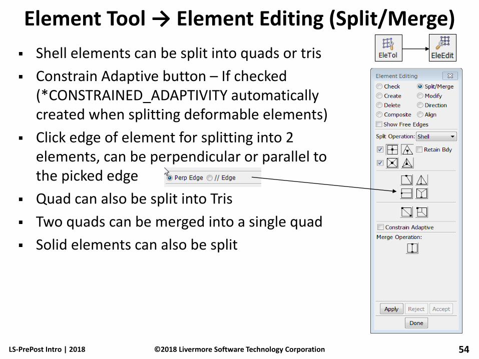
Element Tool → Element Editing (Split/Merge)
Shell elements can be split into quads or tris
Constrain Adaptive button – If checked (*CONSTRAINED_ADAPTIVITY automatically created when splitting deformable elements)
Click edge of element for splitting into 2 elements, can be perpendicular or parallel to the picked edge
Quad can also be split into Tris
Two quads can be merged into a single quad
Solid elements can also be split
LS-PrePost Intro | 2018 54 ©2018 Livermore Software Technology Corporation

Element Tool → Element Editing (Align)
Align – to re-align the connectivity of a group of shell/solid/tshell elements such that the orientation of the elements will be consistent
Pick the face and edge of a seed element, the picked face will be used as face one, and the picked edge will be used as n1->n2 (first edge)
Show Seed only will show the picked element and allow user to select different face/edge
Show normal, show direction will show element orientation
LS-PrePost Intro | 2018 55 ©2018 Livermore Software Technology Corporation
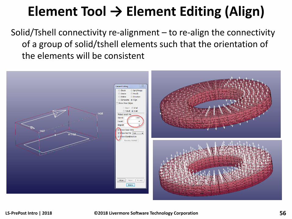
Element Tool → Element Editing (Align)
LS-PrePost Intro | 2018 56 ©2018 Livermore Software Technology Corporation
Solid/Tshell connectivity re-alignment – to re-align the connectivity of a group of solid/tshell elements such that the orientation of the elements will be consistent
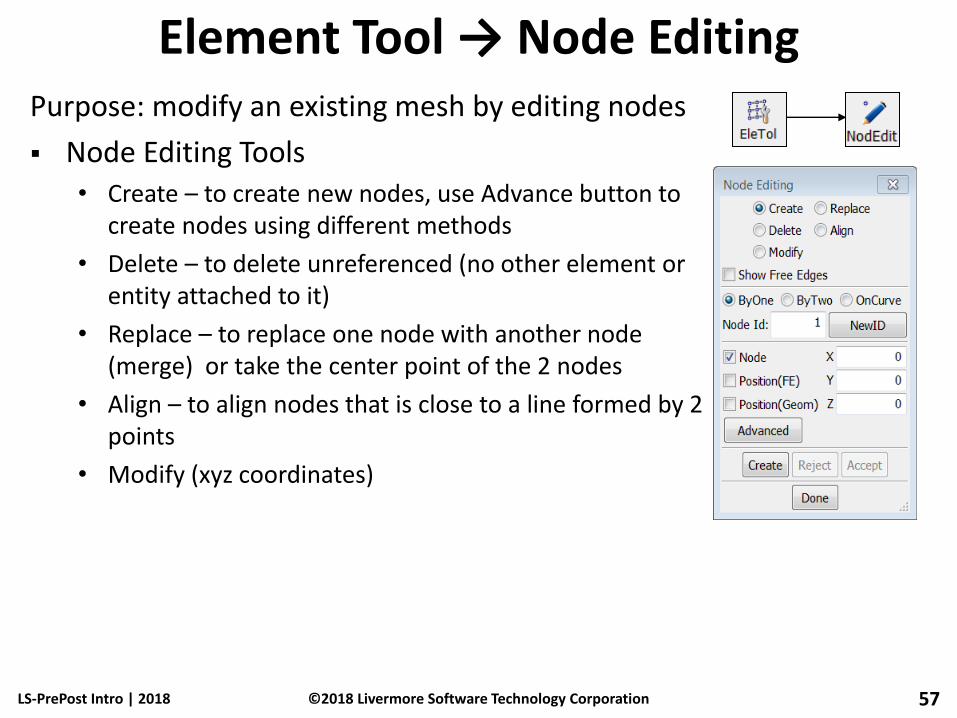
Element Tool → Node Editing Purpose: modify an existing mesh by editing nodes
Node Editing Tools • Create – to create new nodes, use Advance button to
create nodes using different methods
• Delete – to delete unreferenced (no other element or entity attached to it)
• Replace – to replace one node with another node (merge) or take the center point of the 2 nodes
• Align – to align nodes that is close to a line formed by 2 points
• Modify (xyz coordinates)
LS-PrePost Intro | 2018 57 ©2018 Livermore Software Technology Corporation

Element Tool → Node Editing (Replace) Two nodes replacement
• Merge two nodes into one
• Option to choose final position of merged node (Node1, Node2, MidPoint)
• Single pick or area select
Multiple (Many) nodes replacement • Merge multiple nodes into one
• Option to choose final position of merged node (Center, Node, Position)
• General Selection interface used to select nodes
LS-PrePost Intro | 2018 58 ©2018 Livermore Software Technology Corporation
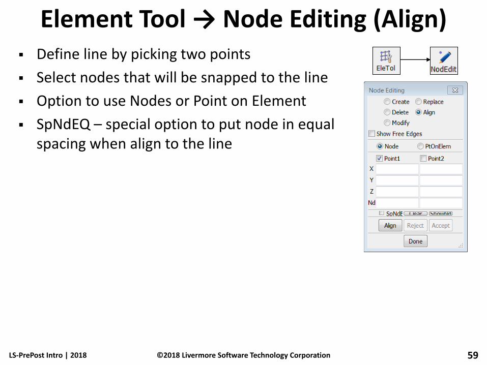
Element Tool → Node Editing (Align) Define line by picking two points
Select nodes that will be snapped to the line
Option to use Nodes or Point on Element
SpNdEQ – special option to put node in equal spacing when align to the line
LS-PrePost Intro | 2018 59 ©2018 Livermore Software Technology Corporation

Element Tools → Normals Purpose: show/reverse/align element normal
Apply to Shell/Segment/Tshell/Cohesive/Solid
For Shell element, positive normal has different color than negative normal
General Selection interface can be used to manually show or reverse normal vectors
Automatic alignment (Auto Reverse) can be performed by picking a “seed” element
LS-PrePost Intro | 2018 60 ©2018 Livermore Software Technology Corporation

Element Tools → Duplicate Nodes show and merge duplicate (coincident) nodes
Tolerance is automatically calculated but can be overridden
Option to keep smaller or larger Node ID
Option to put new node at the xyz centroid of all merged nodes
Show Dup Nodes – will show all the nodes that meet the tolerance criterion
Select Nodes – allow user to select subset of nodes shown
Merge Dup Nodes – will perform the merging of the duplicated Nodes
Option to delete degenerated elements (elements with zero area)
LS-PrePost Intro | 2018 61 ©2018 Livermore Software Technology Corporation

Element Tools → Detach Purpose: detach elements from an existing mesh
Shell, Beam, Solid, Tshell – detach elements by type
Node – detach all elements connected to a node
Element – Select group of elements to be detached
Edge – Select edges of elements to be detached
Starting NID – Enter starting ID for new nodes
LS-PrePost Intro | 2018 62 ©2018 Livermore Software Technology Corporation

Element Tools → Measure Purpose: take measurements of various items
Item – list of available measurements • Coordinate – xyz coordinate
• Dist N2N – distance between 2 nodes
• Dist N2S – distance between a node and a surface
• Dist P2P – distance between 2 points
• Dist E2E 4Node – distance between edge to edge (4nodes)
• Angle 3Node – angle between 3 nodes
• Angle 4node – angle between 2 lines formed by 4 nodes
• 3Pt Radius – the radius formed by 3 nodes
• Area / Volume / Mass / Inertia
• Ang Vel – angular velocity
• Create Axes – to create a local coordinate systems
• Separation – measure distance between two parts in fringe color
LS-PrePost Intro | 2018 63 ©2018 Livermore Software Technology Corporation

Element Tools → Measure (continued...)
Active Elements Only – for certain quantities (e.g., Area, Volume, Mass, Inertia)
Element/Part/All – measure by element, by part, or all
For shell part volume, beside the volume computed by (area x thickness), it also computes the enclosure volume if the part form a water tight enclosure
Cancel pick – remove last picked entity
Apply – take measurement
Reference Axes – select current reference axes for measurement (define axis using Item: Create Axis)
History – depends on selected item
LS-PrePost Intro | 2018 64 ©2018 Livermore Software Technology Corporation
Workshop 3 Model Editing
LS-PrePost Intro | 2018 65 ©2018 Livermore Software Technology Corporation
Model free edge
Duplicate nodes merge
Node and element Editing
Fill holes
Element normal align
Save a keyword file

Pre-Processing (continued…)
LS-PrePost Intro | 2018 66 ©2018 Livermore Software Technology Corporation

Element Tools → Move/Copy Purpose: move or copy elements from one part to
another
Use General Selection interface to select elements
Target part can be a non-existent
Starting IDs for new elements and nodes can be specified when performing a copy
LS-PrePost Intro | 2018 67 ©2018 Livermore Software Technology Corporation
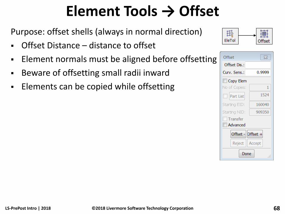
Element Tools → Offset Purpose: offset shells (always in normal direction)
Offset Distance – distance to offset
Element normals must be aligned before offsetting
Beware of offsetting small radii inward
Elements can be copied while offsetting
LS-PrePost Intro | 2018 68 ©2018 Livermore Software Technology Corporation

Element Tools→ Transform (Translate) Purpose: translate nodes/elements/parts
Translate Distance – distance to translate
X,Y,Z directions can be in global or local system
N1-N2 – translate in the direction from N1 to N2
N1-N2-N3 – translate in the direction normal to the plane formed by N1, N2, and N3
N1-to-N2 – translate using the distance and direction between N1 and N2
Pt-to-Pt – translate using the distance and direction between P1 and P2
Sh-Normal – pick a shell element and use its normal as the direction of the translation
LS-PrePost Intro | 2018 69 ©2018 Livermore Software Technology Corporation
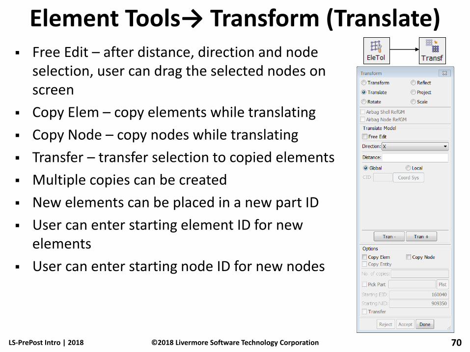
Element Tools→ Transform (Translate) Free Edit – after distance, direction and node
selection, user can drag the selected nodes on screen
Copy Elem – copy elements while translating
Copy Node – copy nodes while translating
Transfer – transfer selection to copied elements
Multiple copies can be created
New elements can be placed in a new part ID
User can enter starting element ID for new elements
User can enter starting node ID for new nodes
LS-PrePost Intro | 2018 70 ©2018 Livermore Software Technology Corporation
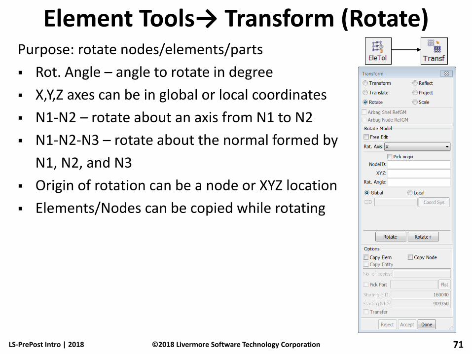
Element Tools→ Transform (Rotate) Purpose: rotate nodes/elements/parts
Rot. Angle – angle to rotate in degree
X,Y,Z axes can be in global or local coordinates
N1-N2 – rotate about an axis from N1 to N2
N1-N2-N3 – rotate about the normal formed by
N1, N2, and N3
Origin of rotation can be a node or XYZ location
Elements/Nodes can be copied while rotating
LS-PrePost Intro | 2018 71 ©2018 Livermore Software Technology Corporation

Element Tools→ Transform (Reflect) Purpose: reflect nodes/elements/parts
Norm X/Y/Z – reflect along global axes
N1-N2 – reflect along the direction from N1 to N2
N1-N2-N3 – reflect along the normal formed by
N1, N2, and N3
Origin of reflection can be a node or
an XYZ location
Elements/Nodes can be copied while reflecting
LS-PrePost Intro | 2018 72 ©2018 Livermore Software Technology Corporation
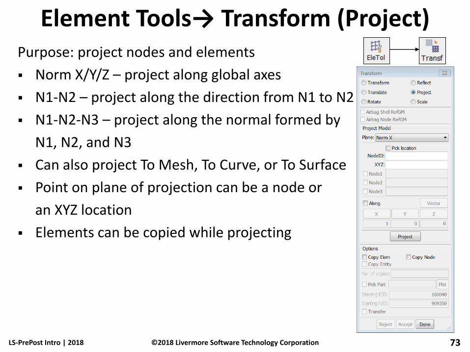
Element Tools→ Transform (Project) Purpose: project nodes and elements
Norm X/Y/Z – project along global axes
N1-N2 – project along the direction from N1 to N2
N1-N2-N3 – project along the normal formed by
N1, N2, and N3
Can also project To Mesh, To Curve, or To Surface
Point on plane of projection can be a node or
an XYZ location
Elements can be copied while projecting
LS-PrePost Intro | 2018 73 ©2018 Livermore Software Technology Corporation

Element Tools→ Transform (Scale) Purpose: scale nodes/elements/parts
Scale Factor – greater than 1 to enlarge, less than 1 to shrink (when using Scale+)
X,Y,Z – scale in either global or local coordinate system
N1-N2 – scale in direction from N1 to N2
N1-N2-N3 – scale in direction of normal formed by N1, N2, and N3
Origin can be a node or a XYZ location
Elements/Nodes can be copied while scaling
LS-PrePost Intro | 2018 74 ©2018 Livermore Software Technology Corporation
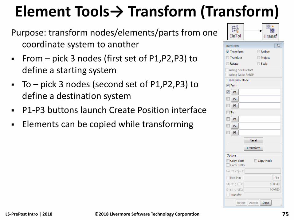
Element Tools→ Transform (Transform) Purpose: transform nodes/elements/parts from one
coordinate system to another
From – pick 3 nodes (first set of P1,P2,P3) to define a starting system
To – pick 3 nodes (second set of P1,P2,P3) to define a destination system
P1-P3 buttons launch Create Position interface
Elements can be copied while transforming
LS-PrePost Intro | 2018 75 ©2018 Livermore Software Technology Corporation

Element Tools → Smooth Purpose: smooth a mesh to improve element quality
Use General Selection interface to select elements
Specified nodes can be locked to prevent movement
Nodes along feature angles are not moved
Boundary nodes can be fixed or free
User specified number of smoothing iterations can be applied
Nodes can be projected back to geometry after smoothing
LS-PrePost Intro | 2018 76 ©2018 Livermore Software Technology Corporation
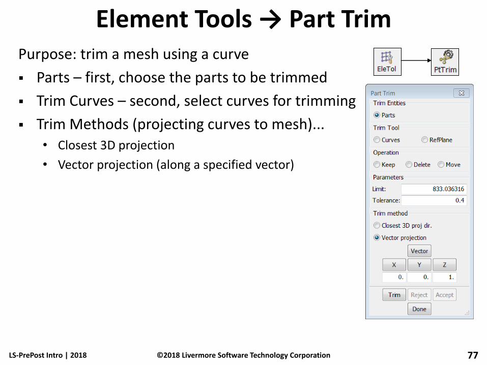
Element Tools → Part Trim Purpose: trim a mesh using a curve
Parts – first, choose the parts to be trimmed
Trim Curves – second, select curves for trimming
Trim Methods (projecting curves to mesh)... • Closest 3D projection
• Vector projection (along a specified vector)
LS-PrePost Intro | 2018 77 ©2018 Livermore Software Technology Corporation
Workshop 4 Build a fan model
LS-PrePost Intro | 2018 78 ©2018 Livermore Software Technology Corporation
Create a surface
Surface mesh
2Line mesh
Part trim
Model transform (rotate)
Save a keyword file

Pre-Processing (continued…)
LS-PrePost Intro | 2018 79 ©2018 Livermore Software Technology Corporation
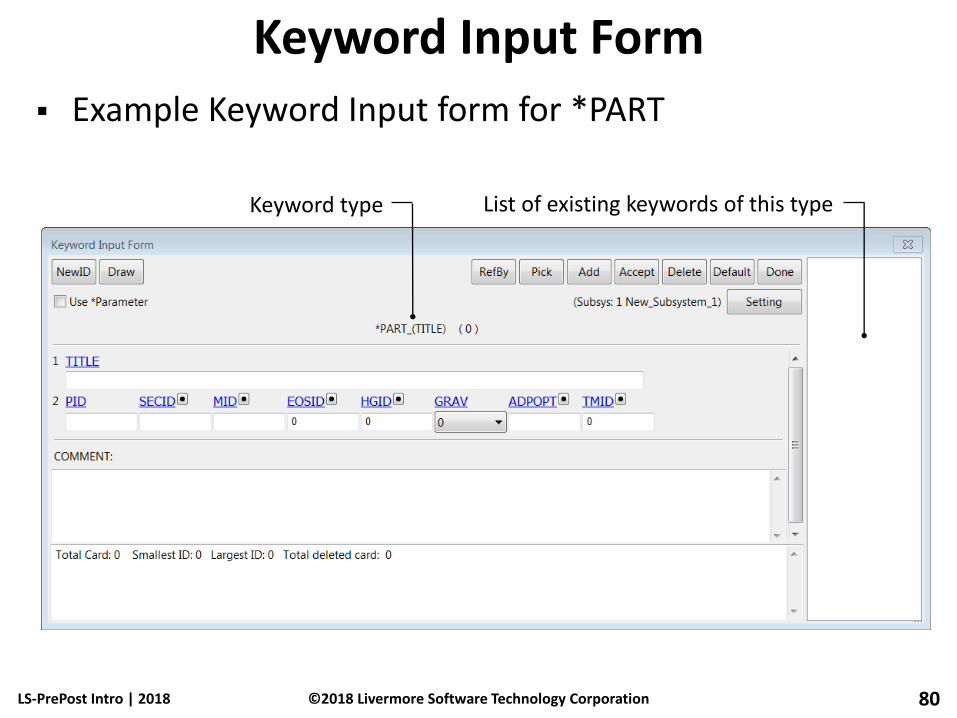
Keyword Input Form
Example Keyword Input form for *PART
LS-PrePost Intro | 2018 80
Keyword type List of existing keywords of this type
©2018 Livermore Software Technology Corporation
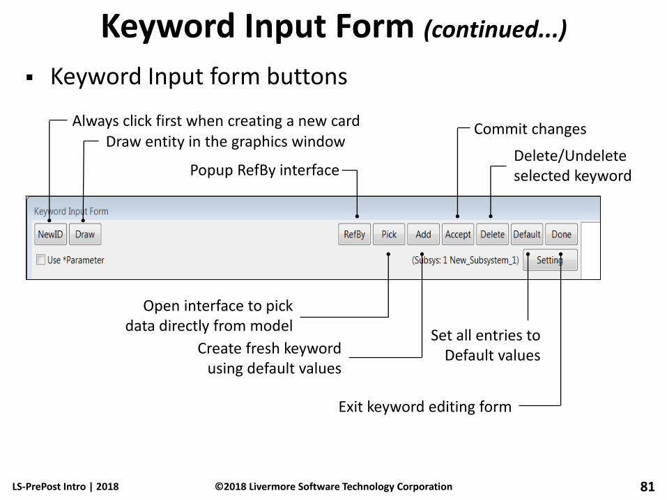
Keyword Input Form (continued...)
Keyword Input form buttons
LS-PrePost Intro | 2018 81
Always click first when creating a new card Draw entity in the graphics window
Open interface to pick data directly from model
Create fresh keyword using default values
Commit changes
Delete/Undelete selected keyword
Set all entries to Default values
Exit keyword editing form
Popup RefBy interface
©2018 Livermore Software Technology Corporation

Keyword Input Form (continued...)
Keyword Input form controls
LS-PrePost Intro | 2018 82
Card Number
Parameter Names
Parameter Values
Link Button
Drop-down Menu
©2018 Livermore Software Technology Corporation

Keyword Input Form (continued...)
Other Keyword Input form features
• Blue parameter titles can be clicked to display description in bottom text area (see below)
• Red parameters indicate that additional cards may be displayed depending on the parameter value
LS-PrePost Intro | 2018 83
Click in any field above to display description here (same information found in LS-DYNA Keyword Manual)
User comments can be entered here
©2018 Livermore Software Technology Corporation
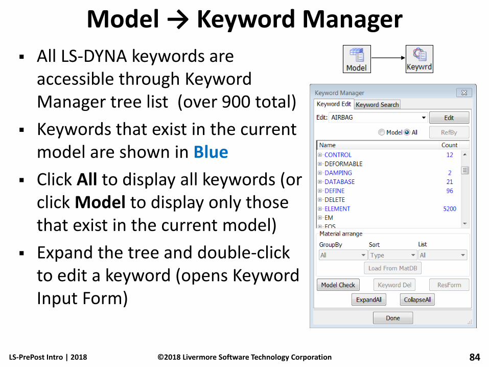
Model → Keyword Manager
All LS-DYNA keywords are accessible through Keyword Manager tree list (over 900 total)
Keywords that exist in the current model are shown in Blue
Click All to display all keywords (or click Model to display only those that exist in the current model)
Expand the tree and double-click to edit a keyword (opens Keyword Input Form)
LS-PrePost Intro | 2018 84 ©2018 Livermore Software Technology Corporation

Model → Keyword Delete and Transfer
Right click on a keyword in the keyword tree opens up the Deletion and Transfer menu
Keyword data can be deleted by all or by IDs
A keyword data can be transferred to another similar keyword data, common fields will be preserved, missing fields will need to be entered. e.g.
*ELEMENT_SHELL_BETA to *ELEMENT_SHELL_THICKNESS
LS-PrePost Intro | 2018 85 ©2018 Livermore Software Technology Corporation
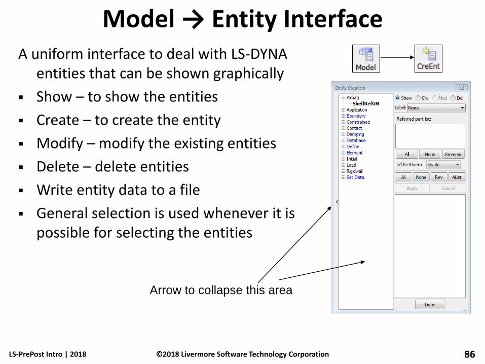
Model → Entity Interface A uniform interface to deal with LS-DYNA
entities that can be shown graphically
Show – to show the entities
Create – to create the entity
Modify – modify the existing entities
Delete – delete entities
Write entity data to a file
General selection is used whenever it is possible for selecting the entities
LS-PrePost Intro | 2018 86 ©2018 Livermore Software Technology Corporation
Arrow to collapse this area
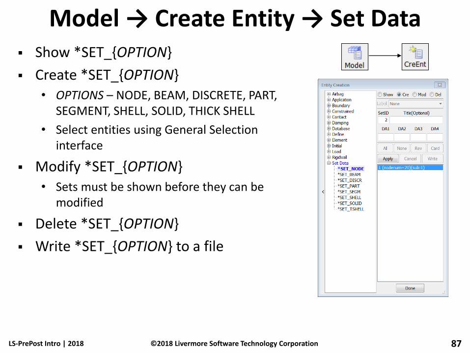
Model → Create Entity → Set Data Show *SET_{OPTION}
Create *SET_{OPTION} • OPTIONS – NODE, BEAM, DISCRETE, PART,
SEGMENT, SHELL, SOLID, THICK SHELL
• Select entities using General Selection interface
Modify *SET_{OPTION} • Sets must be shown before they can be
modified
Delete *SET_{OPTION}
Write *SET_{OPTION} to a file
LS-PrePost Intro | 2018 87 ©2018 Livermore Software Technology Corporation

Boundary → Spc Show *BOUNDARY_SPC_{OPTION}
• Label – None/Symbol/Detail
• Local coordinate systems will be shown if used
• Match – Filter by constrained DOFs
Create *BOUNDARY_SPC_{OPTION} • OPTIONS – NODE, NODE_SET
• Use General Selection interface to select nodes
• Activate constrained DOFs
• Use global or local coordinate system
Modify *BOUNDARY_SPC_{OPTION}
Delete *BOUNDARY_SPC_{OPTION}
LS-PrePost Intro | 2018 88 ©2018 Livermore Software Technology Corporation

Constrained → Nodal Rigid Body (CNRB) Show *CONSTRAINED_NODAL_RIGID_BODY
Create *CONSTRAINED_NODAL_RIGID_BODY • OPTION – SPC
• Use General Selection interface to select nodes
• Set additional flags
Modify *CONSTRAINED_NODAL_RIGID_BODY
Delete *CONSTRAINED_NODAL_RIGID_BODY
LS-PrePost Intro | 2018 89 ©2018 Livermore Software Technology Corporation

Model → Display Entity Purpose: visualize model entities (keywords) other than
nodes and elements (which are displayed by default)
Available options include… • *BOUNDARY_{OPTION}
• *CONSTRAINED_{OPTION}
• *INITIAL_VELOCITY_{OPTION}
• *LOAD_{OPTION}
• *RIGIDWALL_{OPTION}
• *SET_{OPTION}
Use while post-processing by loading d3plots followed by the corresponding keyword file
LS-PrePost Intro | 2018 90 ©2018 Livermore Software Technology Corporation

Model → Part Data There are 7 functions in the Part
Data dialog:
Show – show existing part data
Create – create new part data
Mod – modify existing data
Sear – search parts by parameters
Assign – assign part data properties
Prop – edit properties of part data
Replace – replace a part with another part
LS-PrePost Intro | 2018 91 ©2018 Livermore Software Technology Corporation

Model → Part Data Replace – replace a part in one model
with another part from another model
The second model can be loaded with the “Load” button
LS-PrePost Intro | 2018 92 ©2018 Livermore Software Technology Corporation
Replace this part with
another part that has
finer mesh
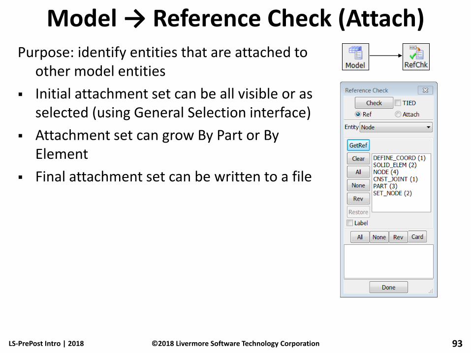
Model → Reference Check (Attach) Purpose: identify entities that are attached to
other model entities
Initial attachment set can be all visible or as selected (using General Selection interface)
Attachment set can grow By Part or By Element
Final attachment set can be written to a file
LS-PrePost Intro | 2018 93 ©2018 Livermore Software Technology Corporation

Model → Renumber Purpose: renumber and offset model
entities
By Keyword – Entities can be renumbered/offset by Keyword • ID range can be specified
• Entities can be picked using the General Selection interface
By Part – Parts/Elements/Nodes can be renumbered/offset by Part
By Selected – Parts/Elements/Nodes can be renumbered/offset by Selected
LS-PrePost Intro | 2018 94 ©2018 Livermore Software Technology Corporation

Model → MSelect → Select
Purpose: switch between loaded models, view multiple models, perform keyword comparison
Select – display selected model(s)
Trans – translate a model (for visualization only, useful for side-by-side animation)
Remove – unload a model
Info – show model summary
LS-PrePost Intro | 2018 95 ©2018 Livermore Software Technology Corporation
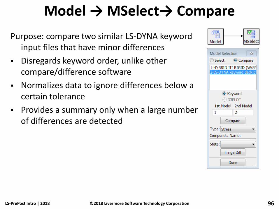
Model → MSelect→ Compare
Purpose: compare two similar LS-DYNA keyword input files that have minor differences
Disregards keyword order, unlike other compare/difference software
Normalizes data to ignore differences below a certain tolerance
Provides a summary only when a large number of differences are detected
LS-PrePost Intro | 2018 96 ©2018 Livermore Software Technology Corporation
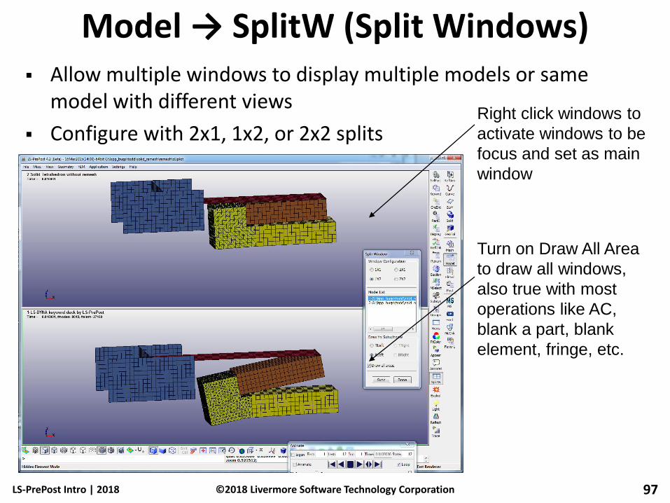
Model → SplitW (Split Windows) Allow multiple windows to display multiple models or same
model with different views
Configure with 2x1, 1x2, or 2x2 splits
LS-PrePost Intro | 2018 97 ©2018 Livermore Software Technology Corporation
Turn on Draw All Area
to draw all windows,
also true with most
operations like AC,
blank a part, blank
element, fringe, etc.
Right click windows to
activate windows to be
focus and set as main
window

Application → Model Checking Element Quality Check: provides
general idea of the quality of the finite element model
Define allowable value, LS-PrePost will show no. of elements that violate the allowable. The violated elements can be saved into general selection buffers
Different checking method for different element types
LS-PrePost Intro | 2018 98 ©2018 Livermore Software Technology Corporation

Application → Model Checking Element Quality Check example: characteristic length
LS-PrePost Intro | 2018 99 ©2018 Livermore Software Technology Corporation
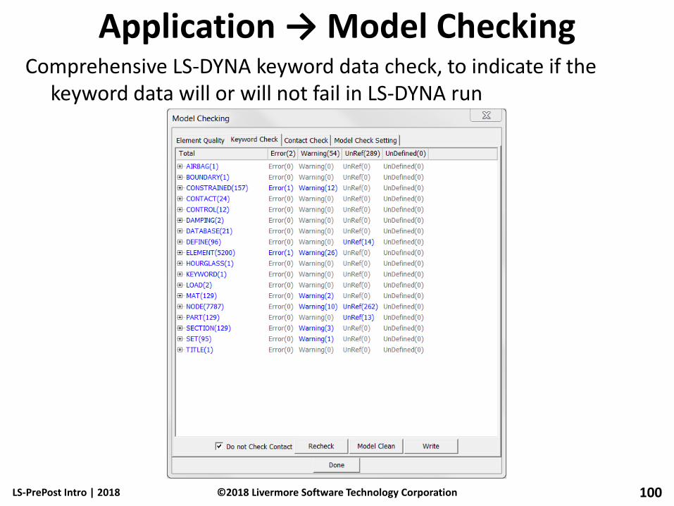
Application → Model Checking Comprehensive LS-DYNA keyword data check, to indicate if the
keyword data will or will not fail in LS-DYNA run
LS-PrePost Intro | 2018 100 ©2018 Livermore Software Technology Corporation

File → Save Keyword As…
Output Version – 960/970/971 (only change if using an old version of LS-DYNA)
Renumber/Offset – can renumber or offset before saving
BySubSystem – activate to save subsystems to separate files (not visible unless model contains subsystems)
Advanced... – additional options (see next slide)
LS-PrePost Intro | 2018 101 ©2018 Livermore Software Technology Corporation

Advanced Settings Interface
Keyword order can be customized
Keywords can be selectively omitted
Title, Field Names, and Comments can be omitted
Parameter names can be output instead of actual values
LS-PrePost Intro | 2018 102 ©2018 Livermore Software Technology Corporation

File → Save Active Keyword As…
Output Version – 960/970/971 (only change if using an old version of LS-DYNA)
Keywords can be selectively output using the Advanced Setting interface
LS-PrePost Intro | 2018 103 ©2018 Livermore Software Technology Corporation
Workshop 5 Create a Keyword File
(S-Rail to Rigidwall Impact)
LS-PrePost Intro | 2018 104 ©2018 Livermore Software Technology Corporation
Mesh model
Assign material and property
Apply mass, constraint and velocity
Rigid wall creation
Define spot welding
Save a keyword file
Model comparison

Post-Processing
LS-PrePost Intro | 2018 105 ©2018 Livermore Software Technology Corporation
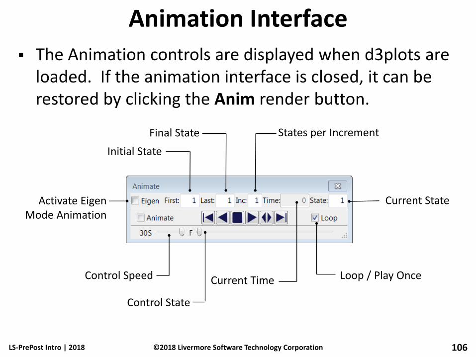
Animation Interface
The Animation controls are displayed when d3plots are loaded. If the animation interface is closed, it can be restored by clicking the Anim render button.
LS-PrePost Intro | 2018 106
Initial State
Final State States per Increment
Loop / Play Once Current Time
Current State
Control Speed
Control State
Activate Eigen Mode Animation
©2018 Livermore Software Technology Corporation
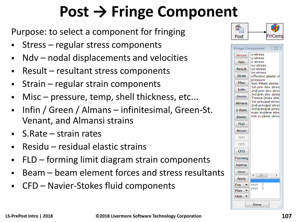
Post → Fringe Component Purpose: to select a component for fringing
Stress – regular stress components
Ndv – nodal displacements and velocities
Result – resultant stress components
Strain – regular strain components
Misc – pressure, temp, shell thickness, etc...
Infin / Green / Almans – infinitesimal, Green-St. Venant, and Almansi strains
S.Rate – strain rates
Residu – residual elastic strains
FLD – forming limit diagram strain components
Beam – beam element forces and stress resultants
CFD – Navier-Stokes fluid components
LS-PrePost Intro | 2018 107 ©2018 Livermore Software Technology Corporation

Post → Fringe Component (continued...)
Frin – choose rendering type • Frin – default fringing
• Isos – iso-surfaces for solid
• Lcon – line contours
• XFrn – fringe max value through all states
• FMes – fringe color on the mesh
• Expr – user define expression
Max – location of shell surfaces • Low / Mid / Upp – lower, mid-plane, and upper
• Max / Ave / Min – maximum, average, minimum
• Ipt – shell integration point
• Bpt – beam integration point
Glob – coordinate system • Glob / Loca – global or local
LS-PrePost Intro | 2018 108 ©2018 Livermore Software Technology Corporation

Post → Fringe Range Purpose: control fringe and iso-surface ranges
Dynamic – min/max adjusted for each time state
Static – same min/max for all the states
User – custom min/max for all the states
Show – show elements within the specified range
Entire Model – legend based on entire model
Active Parts Only – legend based on displayed parts
Active Elements Only – legend based on displayed elements only
LS-PrePost Intro | 2018 109 ©2018 Livermore Software Technology Corporation
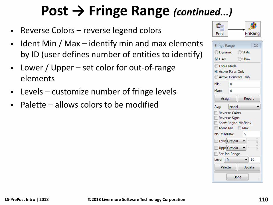
Post → Fringe Range (continued...)
Reverse Colors – reverse legend colors
Ident Min / Max – identify min and max elements by ID (user defines number of entities to identify)
Lower / Upper – set color for out-of-range elements
Levels – customize number of fringe levels
Palette – allows colors to be modified
LS-PrePost Intro | 2018 110 ©2018 Livermore Software Technology Corporation

Plot Window Drawing XY curves for History/ASCII/Binout/XYPlot
LS-PrePost Intro | 2018 111 ©2018 Livermore Software Technology Corporation

Plot Window (continued...)
Title – modify main, axis, legend, and curve titles
Attr – modify curve attributes (symbol, color, width, style)
LS-PrePost Intro | 2018 112 ©2018 Livermore Software Technology Corporation

Plot Window (continued...)
Filter – filter curves (SAE, Butterworth, COS, etc...)
Save – write curves to file (.crv, Keep, XY Pairs, .csv, .xml)
LS-PrePost Intro | 2018 113 ©2018 Livermore Software Technology Corporation
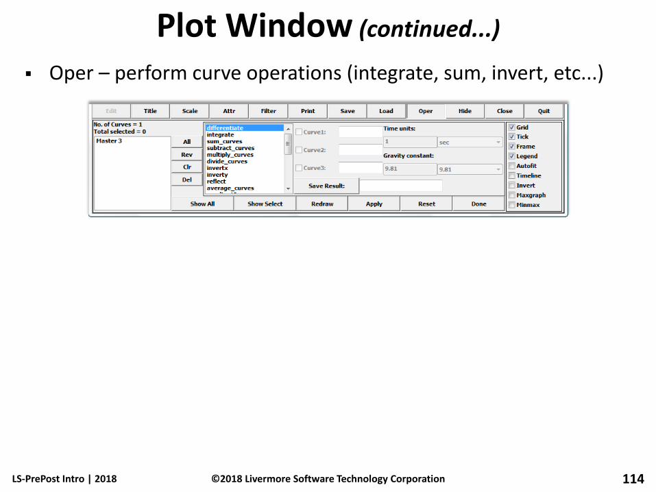
Plot Window (continued...)
Oper – perform curve operations (integrate, sum, invert, etc...)
LS-PrePost Intro | 2018 114 ©2018 Livermore Software Technology Corporation
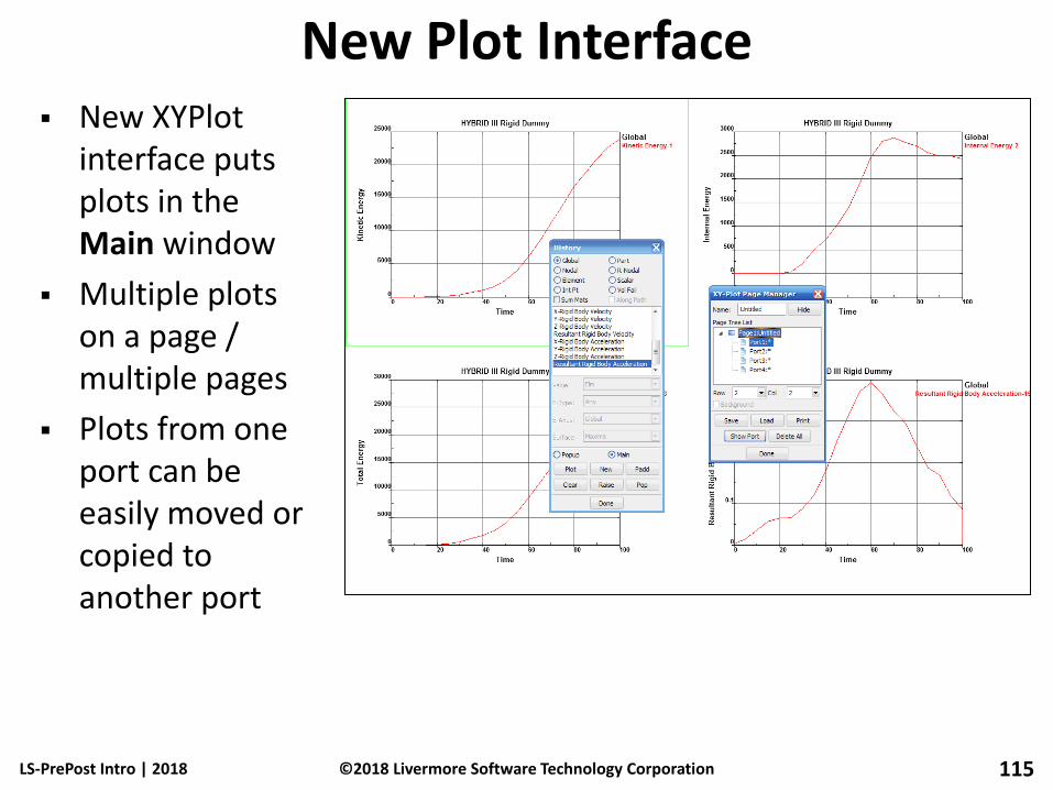
New Plot Interface New XYPlot
interface puts plots in the Main window
Multiple plots on a page / multiple pages
Plots from one port can be easily moved or copied to another port
LS-PrePost Intro | 2018 115 ©2018 Livermore Software Technology Corporation
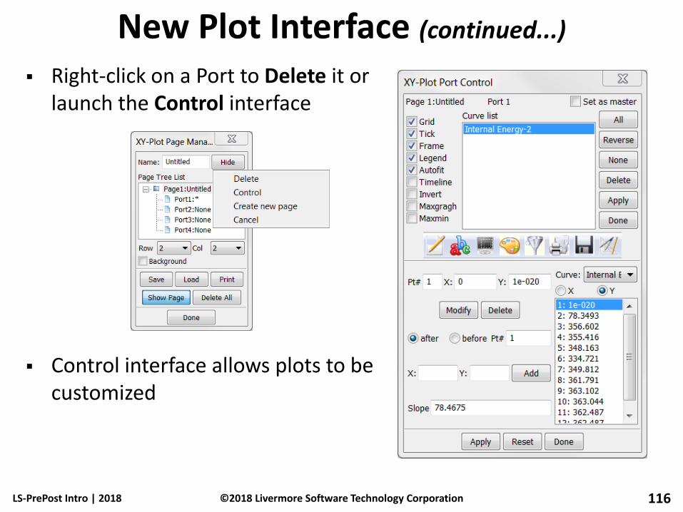
New Plot Interface (continued...)
Right-click on a Port to Delete it or launch the Control interface
Control interface allows plots to be customized
LS-PrePost Intro | 2018 116 ©2018 Livermore Software Technology Corporation

Post → History Purpose: plot time history data (from d3plots)
Global – energies and kinematic data for full model
Part – energies and kinematic data for parts
Nodal – kinematic data for nodes
Element – stress and strain data for elements • Value – set to element value or min/max value for the
part
• E-Type – choose element type to plot history
• E-Axes – global or local
• Surface – choose shell location (through-thickness)
Int Pt – integration point data
Scalar – plot scalar value that is being fringed (choose component in Fcomp interface)
LS-PrePost Intro | 2018 117 ©2018 Livermore Software Technology Corporation

Post → History (continued...)
Standard plotting options... • Plot – plot selected value in current Plot Window
• New – plot selected value in new Plot Window
• Padd – add selected value to current Plot Window
• Raise – bring forward all open plot windows
• Pop – open and bring forward all closed plot windows
Interfaces that use these plot functions... • History
• XYPlot
• ASCII
• Binout
• FLD
• Measure
• Section > Force
LS-PrePost Intro | 2018 118 ©2018 Livermore Software Technology Corporation

Post → ASCII Purpose: create XY-Plots from ASCII output files
ASCII File Operations... • File – browse and load ASCII file from any directory
• Load – load selected file type from current directory
• Unload – unload files from memory
• All – select all items in the list
• Clear – clear selected items
• Rev – reverse selection
• Info – show information on the loaded ASCII file
• Multiple Select – plot multiple curves at once when multiple files are loaded (using File option above)
LS-PrePost Intro | 2018 119 ©2018 Livermore Software Technology Corporation
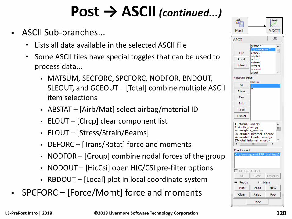
Post → ASCII (continued...)
ASCII Sub-branches... • Lists all data available in the selected ASCII file
• Some ASCII files have special toggles that can be used to process data...
MATSUM, SECFORC, SPCFORC, NODFOR, BNDOUT, SLEOUT, and GCEOUT – [Total] combine multiple ASCII item selections
ABSTAT – [Airb/Mat] select airbag/material ID
ELOUT – [Clrcp] clear component list
ELOUT – [Stress/Strain/Beams]
DEFORC – [Trans/Rotat] force and moments
NODFOR – [Group] combine nodal forces of the group
NODOUT – [HicCsi] open HIC/CSI pre-filter options
RBDOUT – [Local] plot in local coordinate system
SPCFORC – [Force/Momt] force and moments
LS-PrePost Intro | 2018 120 ©2018 Livermore Software Technology Corporation
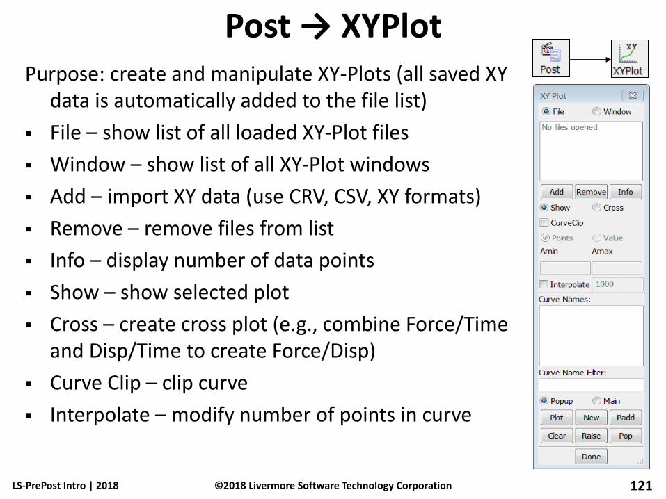
Post → XYPlot Purpose: create and manipulate XY-Plots (all saved XY
data is automatically added to the file list)
File – show list of all loaded XY-Plot files
Window – show list of all XY-Plot windows
Add – import XY data (use CRV, CSV, XY formats)
Remove – remove files from list
Info – display number of data points
Show – show selected plot
Cross – create cross plot (e.g., combine Force/Time and Disp/Time to create Force/Disp)
Curve Clip – clip curve
Interpolate – modify number of points in curve
LS-PrePost Intro | 2018 121 ©2018 Livermore Software Technology Corporation

Post → Binout Purpose: plot data from binout files
Binout contains same data as ASCII files but in binary format
Set BINARY=2 on *DATABASE_{OPTION} to generate binout file
Load – load binout file (multiple binout files can be loaded)
Unload – unload binout file
Save – save binout branch in ASCII format
Done – exit the Binout interface
LS-PrePost Intro | 2018 122 ©2018 Livermore Software Technology Corporation
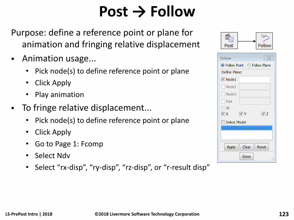
Post → Follow Purpose: define a reference point or plane for
animation and fringing relative displacement
Animation usage... • Pick node(s) to define reference point or plane
• Click Apply
• Play animation
To fringe relative displacement... • Pick node(s) to define reference point or plane
• Click Apply
• Go to Page 1: Fcomp
• Select Ndv
• Select “rx-disp”, “ry-disp”, “rz-disp”, or “r-result disp”
LS-PrePost Intro | 2018 123 ©2018 Livermore Software Technology Corporation

Post → Trace Purpose: trace nodal displacements
Use General Selection interface to select nodes
Set width and color of trace line
Select state to begin trace
Output trace in several formats... • *DEFINE_CURVE
• Coordinate history
• *BOUNDARY_PRESCRIBED_MOTION_NODE
LS-PrePost Intro | 2018 124 ©2018 Livermore Software Technology Corporation
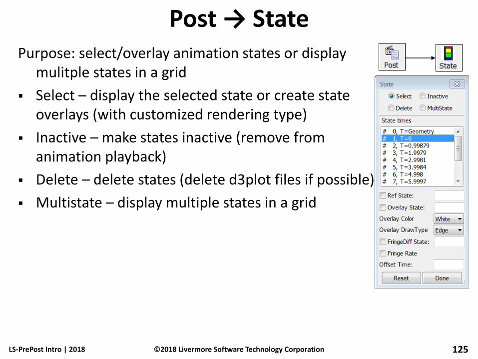
Post → State Purpose: select/overlay animation states or display
mulitple states in a grid
Select – display the selected state or create state overlays (with customized rendering type)
Inactive – make states inactive (remove from animation playback)
Delete – delete states (delete d3plot files if possible)
Multistate – display multiple states in a grid
LS-PrePost Intro | 2018 125 ©2018 Livermore Software Technology Corporation

Post → Output Purpose: output post-processing data
Some available formats... • LS-DYNA Keyword
• Nastran
• Dynain ASCII
• ASCII and Binary STL
Active Parts Only – write only displayed parts
Entire Model – write entire model (use check boxes to control exactly which entities are written)
St No – Controls which state is written
LS-PrePost Intro | 2018 126 ©2018 Livermore Software Technology Corporation

Post → Vector Purpose: create vector plots (similar to fringing)
d3plot (binary plot) options... • Shell Normal
• Displacement
• Velocity
• Principal Stress
• Principle Strain
intfor (interface force file) options... • Force
• Pressure
• Surface Shear
LS-PrePost Intro | 2018 127 ©2018 Livermore Software Technology Corporation

Post → Vector (continued...)
X, Y, and Z components for displacement, velocity and force can be selected
Range settings... • Dynamic – min/max adjusted for each time state
• Static – same min/max for all the states
• User – custom min/max for all the states
• Show – show vectors within the specified range
Display settings... • SF – set vector size scale factor
• Whole – display vectors for the whole model
• Part – display vectors for a specific part
• Area – display vectors for a user defined area
• El/Node – display vectors for specific elements/nodes
LS-PrePost Intro | 2018 128 ©2018 Livermore Software Technology Corporation
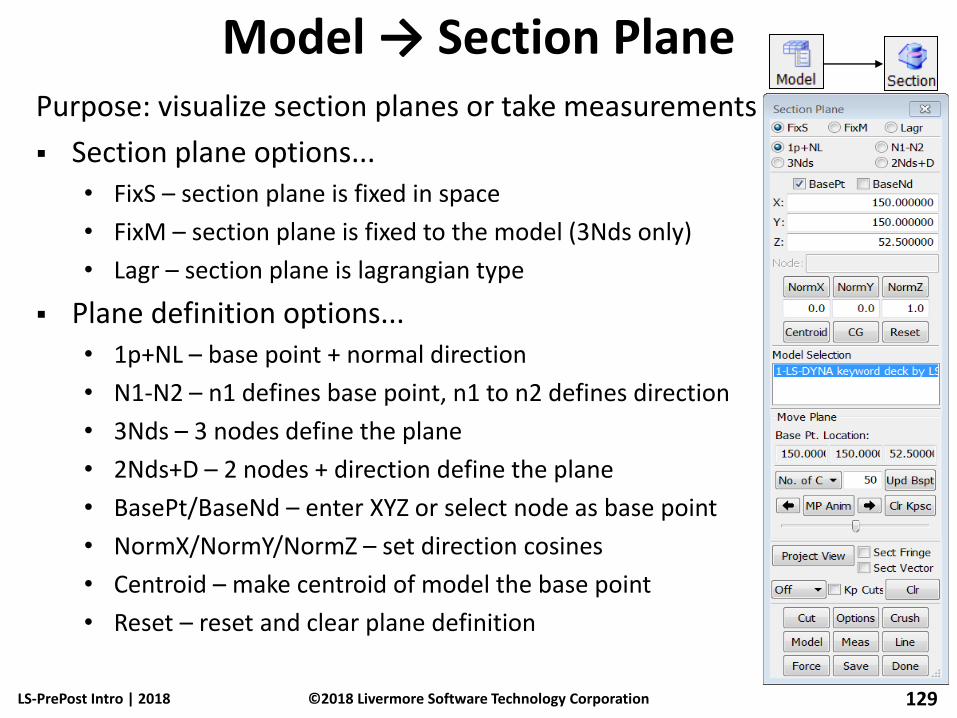
Model → Section Plane Purpose: visualize section planes or take measurements
Section plane options... • FixS – section plane is fixed in space
• FixM – section plane is fixed to the model (3Nds only)
• Lagr – section plane is lagrangian type
Plane definition options... • 1p+NL – base point + normal direction
• N1-N2 – n1 defines base point, n1 to n2 defines direction
• 3Nds – 3 nodes define the plane
• 2Nds+D – 2 nodes + direction define the plane
• BasePt/BaseNd – enter XYZ or select node as base point
• NormX/NormY/NormZ – set direction cosines
• Centroid – make centroid of model the base point
• Reset – reset and clear plane definition
LS-PrePost Intro | 2018 129 ©2018 Livermore Software Technology Corporation

Model → Section Plane (continued...)
Additional options... • No. of Cut/Distance - divide model along the plane normal
direction
• Right/Left Arrows – move the plane forward/backward
• MP Anim – animate the section
• Upd Bspt – update base point with current position
• Clear Kpsc – clear all kept section cuts from memory
LS-PrePost Intro | 2018 130 ©2018 Livermore Software Technology Corporation
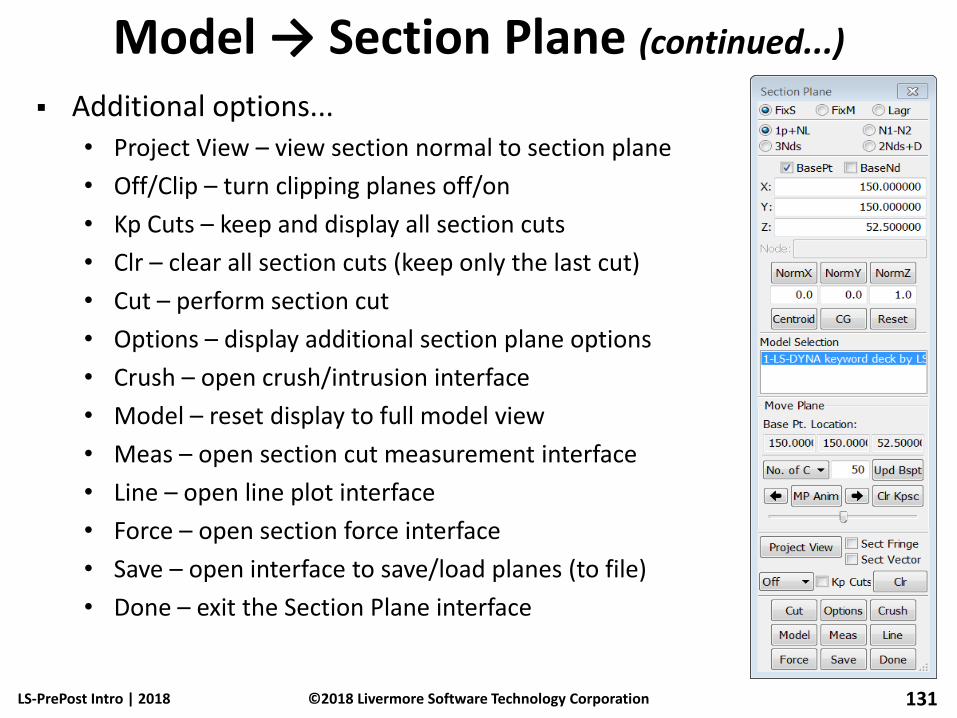
Model → Section Plane (continued...)
Additional options... • Project View – view section normal to section plane
• Off/Clip – turn clipping planes off/on
• Kp Cuts – keep and display all section cuts
• Clr – clear all section cuts (keep only the last cut)
• Cut – perform section cut
• Options – display additional section plane options
• Crush – open crush/intrusion interface
• Model – reset display to full model view
• Meas – open section cut measurement interface
• Line – open line plot interface
• Force – open section force interface
• Save – open interface to save/load planes (to file)
• Done – exit the Section Plane interface
LS-PrePost Intro | 2018 131 ©2018 Livermore Software Technology Corporation

Model → Section Plane (continued...)
“Options” Interface • ShowPl – show section plane on/off
• 3DOutline – show solid part outline after cut
• ShMesh – show section plane as mesh
• Line Width – set section cut line width
• Line Color – set section cut line color
• Color/Cut – use different color for each cut instead of different color for each part
• Thickness – draw section cut with thickness
• VP – draw vector on section cut
• Write – write section cut to file in selected format (Keyword, VGA, or IGES)
• Curr State – set current state for writing
LS-PrePost Intro | 2018 132 ©2018 Livermore Software Technology Corporation

Model → Section Plane (continued...)
“Crush” Interface – measure distance from node to plane (intrusion plotting) • Line Width – Intrusion plot line width
• Line Color – Intrusion plot line color
• PlotType – select history plot type
• Node ID – can be picked or keyed in
“Line” Interface – plot fringe values at section cut along the length of the cut • Mainly used for metal stamping
• Must load fringe value (using Fcomp) and perform cut first
• Pick a part for the line plot
LS-PrePost Intro | 2018 133 ©2018 Livermore Software Technology Corporation
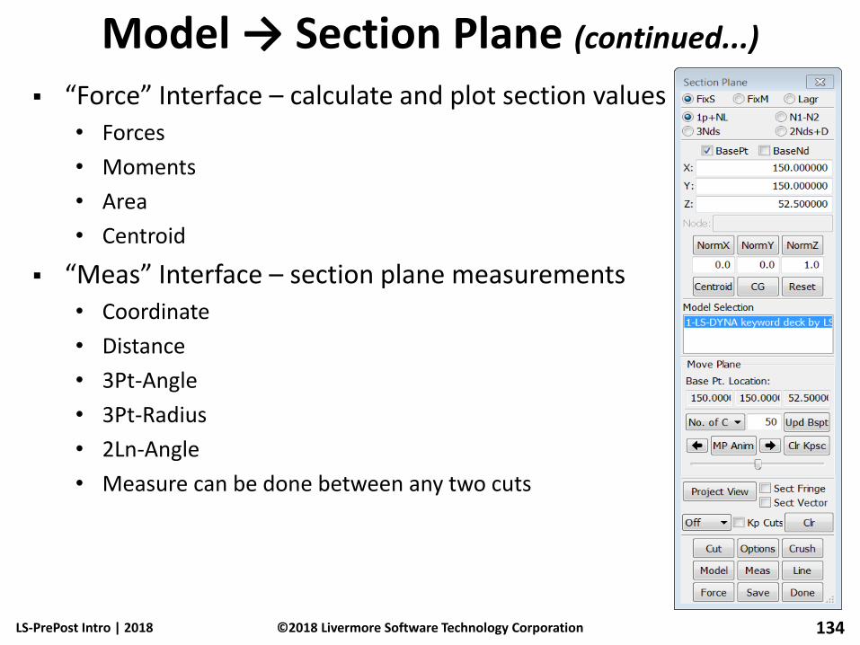
Model → Section Plane (continued...)
“Force” Interface – calculate and plot section values • Forces
• Moments
• Area
• Centroid
“Meas” Interface – section plane measurements • Coordinate
• Distance
• 3Pt-Angle
• 3Pt-Radius
• 2Ln-Angle
• Measure can be done between any two cuts
LS-PrePost Intro | 2018 134 ©2018 Livermore Software Technology Corporation
Configuration
Configuration files
• Lsppconf – record general configuration parameters, user the pull down menu “Setting”->”Configuration Settings” to set parameters
• Lspplasttouch – record last session windows size, dialog location, file path, etc.
• Configuire_Toolbar.cfg – record toolbar configurations
• .lspp_recent – record recently used files and their locations
Configuration file location (each version of LS-PrePost has its own directory)
• Windows – C:\Users\uname\AppData\Roaming\LSTC\LS-PrePostx.x
• Linux - $HOME/LSTC/LS-PrepostX.x
LS-PrePost Intro | 2018 135 ©2018 Livermore Software Technology Corporation
Function Keys
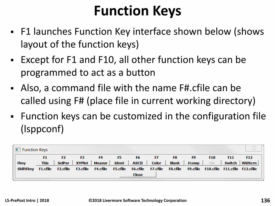
F1 launches Function Key interface shown below (shows layout of the function keys)
Except for F1 and F10, all other function keys can be programmed to act as a button
Also, a command file with the name F#.cfile can be called using F# (place file in current working directory)
Function keys can be customized in the configuration file (lsppconf)
LS-PrePost Intro | 2018 136 ©2018 Livermore Software Technology Corporation

Workshop 6 Post-Processing
LS-PrePost Intro | 2018 137 ©2018 Livermore Software Technology Corporation
Animation interface
Fringe (contour) plotting
Time history/ASCII data plotting
Section cut
Cross plotting
Vector draw

LS-PrePost Intro | 2018 ©2018 Livermore Software Technology Corporation 138
Thank You!