introduction to micro-controllers · pdf filemany example arduino-projects will rely on...
TRANSCRIPT

PH-315 Portland State University
INTRODUCTION to MICRO-CONTROLLERS
Bret Comnes
1. ABSTRACT
A microcontroller is an integrated circuit containing a processor and programmable read-only
memory,1 which is widely used as an interface between hardware and software systems. This
laboratory session pursues obtaining familiarity with microcontrollers operation, namely installation of
communication with your computer, downloading the proper software, and programming code.
In Part-I, an “Arduino Leonardo” microcontroller will be used to implement simple, still, very
instructive tasks.
I. A) Programs will be loaded into the microcontroller through the computer serial port (afterwards
the microcontroller can act somewhat independently, executing the task it was programed for).
This will be covered in sections 2 to 7.
I. B) Section 8 shows how to establish a communication in real time between the Arduino and
other devices (over the serial line):
i) The Arduino will communicate with an external program (Processing) running on our computer.
ii) Setting up the Arduino to respond to messages sent to it by a computer over the serial port
Part-II includes the implementation of a proportional, integral, derivative (PID) controller, which is
used to regulate the amount of light emitted by a light emitting diode (LED). The PID controller's
function is to adjust the amount of LED light incident on the photoresistor as needed to keep the
voltage across the photoresistor’s terminals at a desired value.
The examples will require some knowledge of pulse-width-modulation PWM (a widely use technique
for converting an analog signal into a digital one). A short note on PWM is attached at the end of this
Part-I file. Once familiarized with the microcontroller operation, you will be required to implement a
PID controller to automate the response of a fan to the input signal from a thermistor.
Microcontrollers Part-I
SECTION I.A
2. INTRODUCTION
Microcontrollers are small computers designed to go where desktop computers dare not to. A
microcontroller is essentially a small programmable computer contained on a single integrated circuit,
consisting of a processor, read-only memory (ROM) used to store the program instructions, and a
set of input and output pins which can be used to interact with an external circuit.
The microcontroller IC is a digital device, and since the processor operates on transistor to
transistor logic (TTL), only two logic states are acceptable, HIGH (~ +5 V), and LOW (~0 V). The
microcontrollers come in all shapes, sizes, and layouts. Usually, they are quite small and use less
power than traditional computers. Microcontrollers are often deployed in ‘appliances’ and serve an
1 The fixed relationship between input and output distinguishes the ROM from other memory circuits.

unmodifiable dedicated purpose, such as keeping track of what spin cycle your washing machine is
on, or how much time is left before it should turn off your microwave oven. Make no mistake,
however, these are general purpose computers.
A major difference between a microcontroller and traditional computers is that they come
with an array of analog and digital inputs and outputs. These inputs and outputs can be used to
read environmental data from sensors, talk to other computers or devices and electronically
control other systems which provide environmental outputs such as a LCD screens, mechanical
switches or servo motors etc.1
Getting started with microcontrollers can be a tedious process, as they can require a number of
supporting circuits, USB controllers, programmers, boot-loaders and power supplies just to load
your first program onto the microcontroller chip. Often times you will start with a prototyping
board which puts all of the necessary components in a convenient, ready to use package.
2.1 Arduino Microcontroller and its advantages
This lab will be using the single board Arduino Leonardo Microcontroller.2 It is similar to the
Arduino Uno,3 with the major difference being that the latter uses Surface Mount Technology
(SMT)4 instead of the older “thru-hole” 5 technology.
Arduino drastically lowers the difficulty of getting started with a microcontroller (compared to to
plain ATMEGA/PIC/ARM chips), as it provides all the necessary tools for making the
microcontroller do interesting things, which would be daunting if staring with just a plain
microcontroller chip.
The Arduino is based around an 8-bit Atmel AVR microcontroller, and has supporting
systems like a boot loader for uploading programs, a USB controller, as well as a barrel jack for
external power.
The Arduino is programmed using a language that is based off of C++ and uses an “integrated
development environment” (IDE) for writing, compiling and uploading your programs to the board.
Many example Arduino-projects will rely on programs running on your computer using Processing
(an open source programming language), but can interface with any serial enabled programs.6,7
Figure 1: T h e Arduino Leonardo Microcontroller[2].
“Arduino is a tool for making computers that can sense and control more of the

physical world than your desktop computer. It’s an open-source physical computing
platform based on a simple microcontroller board, and a development environment
for writing software for the board.” – Arduino.cc8
3 . GETTING STARTED
This lab is based off of the Arduino 1.0.3 software which can be downloaded for free from the
Arduino website.9 Unlike other embedded systems development environments, the Arduino software
is quick to download and set up, and has zero cost associated with the software which makes it a
convenient to work with when your primary goal is to come up with a working prototype quickly and
cheaply. There is a large community of Arduino users and there exists a massive pool of example
programs and libraries compared to other educational prototyping boards.
Whatever you do, DO NOT APPLY MORE THAN 5V TO ANY PIN ON THE
ARDUINO. Otherwise it will damage or destroy the microcontroller board. Also, avoid
powering directly with the Arduino devices that draw high current. Instead opt for a separate power
source and an NPN transistor or something similar. Basically, avoid finding creative ways to
break the equipment.
3.1 Find a Computer
You are free to use your own laptop or one of the classroom computers. Plug your
Arduino into the computer using the micro USB cable. Please be careful with the
delicate connectors.
3.2 Download and Launch the Arduino Software
Download the latest Arduino Integrated Development Environment (IDE)9 available at the
following site,
http://arduino.cc/en/Main/Software
[If you have decided to use your own Arduino, make sure you find the necessary USB drivers if
you have a board that is older than the Uno. You may also check around class to see if the Arduino
software is available on someone’s USB drive.]
At the time of writing these notes, we selected Arduino 1.0.5 from the menu.
The downloading process may take a few minutes.
Then go to the “downloads” folder in your computer (typically located in the “favorites section),
identify with your mouse the Arduino application file, and enter a left-click.
After a few minutes, the monitor screen should pop-up the following message: “Do you want to
allow this program making change in your computer?” Proceed accordingly.
(You may be prompted to add hardware if you are on windows. If it asks for a driver, tell the
windows driver wizard to look inside a folder called drivers inside the Arduino folder. If the
computer you are using already has the Arduino software downloaded, look inside that folder
usually found in Program Files, or wherever you copied it, or the shortcut on the desktop leads
too.)
3.3 Selecting the Board

The Arduino application software is now installed in your computer. It should be available from the
Start menu (lower left corner) of your computer
Click on the Arduino application to launch the Arduino Integrated Development Environment
(IDE).
It is time now to tell the Arduino IDE what particular Arduino board we will be using (i.e. to tell the
IDE what hardware it will be compiling). For that purpose, once the IDE is open, navigate to the
toolbar and select the Leonardo board,
Toolbar → Tools → Board → Arduino Leonardo
If you are using a different board, select the one you have from this list instead.
This step may vary from system to system.
3.4 Selecting a Serial Port
This step varies from system to system. This step is to tell the computer which serial port the
Arduino chip can be reached at, for both programing the board as well as talking to it during
runtime.
Figure 2: Port selection in Windows and OS X.
Note: Sometimes, even if the port selection has been set through the
Arduino program (as described above), it may be necessary to specify
the serial port though
Left-click the “Start” button; right click on “Computer”, select
“properties >> Left-click on “Device Manager” >> Ports

3.4.1 Windows
Select Toolbar → Tools → Serial Port → COM5
where COM5 is the serial port that has been assigned to your Arduino by windows. (The computer
may have assigned another port number to your Arduino, like COM4, for example; check it out).
You may have more than one port in the list. To know which port is associated with the Arduino,
you can check the list with the Arduino unplugged, and check it again with it plugged in. The
port that appears after is the Arduino’s port.
3.4.2 OS X
Usually the Arduino is the first item in the Serial Port list. Another way to tell is that it has tty in
the name and does not have the world ‘bluetooth’ in it.
3.5 Compiling and uploading your first program (The “Blink” program)
Next we will open an example program; we have chosen the “blink” program available in the
Arduino library. For that purpose, navigate to,
Toolbar → File → Examples → 01. Basics → Blink
The program shown in Fig. 5 will appear in your screen.
We proceed now to verify that it compiles, and then to upload it to your board.
Compiling your program lets the compiler check your work for syntax and structure errors.
Press the verify button (top-left side of the screen; see also Fig. 3).
It will take some minutes to compile the sketch, and then to return a ‘Done compiling’ message (see
Figure 3). If you get an error, something went wrong.
Figure 3. Left: The “Verify” and “ Compile” buttons. Right: Successful-compile message.
Once the compiling process is completed, go ahead and upload the program to the micro-controller
board by pressing the upload button (located right next to the verify button).
This process should provide a similar completion message after a few seconds. The LEDs on the
Arduino will blink during the upload, but should settle down after a few seconds. Your program is now
on the Arduino and running in a loop sequence.
Once the program you uploaded is running, the tiny LED labeled ‘L’ on your Arduino should be
slowly blinking in response to the uploaded “Blink” program. The LED labeled ‘L’ is wired to Pin 13
on the Arduino, a digital pin with a resistor built in so that an LED can be connected directly between
that pin and ground. Go ahead and connect an LED between Pin 13 and GND. It should blink at the

same rate as the ‘L’ LED on the board.
Congratulations! You now have a working Arduino that is talking to the Arduino IDE.
4. PROGRAMMING the ARDUINO
Arduino is based off the Processing6 (an open source programming language) which has some
similarities to C. However much of the language has been simplified from C. In this section we
will go over the basics of the language, look at some simple examples of code, and even write
some of our own.
4.1 The Bare Minimum
The bare minimum code you need for an Arduino program is presented in Figure 4.
1 void setup()
2 // put your setup code here, to run once:
3 4 void loop()
5 // put your main code here, to run repeatedly:
6
Figure 4: The minimum amount of code for an Arduino Program.
There are two parts to this minimum program,
the void setup() section, and
the void loop() section.
When your program runs, it starts executing your code line by line, starting with the void
setup() section; your program will execute any code that is inside the brackets, .
Next, i t will start executing the code inside void loop() , until it gets to the end of the
available instructions, at which point, the program starts back over in at the beginning of void
loop() , retaining any variables or settings from prior lines of code.
Let’s look at a simple example that you should already have pulled up, the Blink program,
which is found in Figure 5. If you still need to open this, refer to Section 3.5.
5. UNDERSTANDING the Blink Program ____________________________________________________________________________________
1 /*
2 Blink
3 Turns on an LED on for one second, then off for one second, repeatedly. 4
5 This example code is in the public domain.
6 */ 7
8 // Pin 13 has an LED connected on most Arduino boards.
9 // Give it a name:
10 int led = 13;
11

12 // the setup routine runs once when you press reset:
13 void setup()
14 // initialize the digital pin as an output.
15 pinMode(led, OUTPUT);
16
17
18 // the loop routine runs over and over again forever:
19 void loop()
20 digitalWrite(led, HIGH); // turn the LED on (HIGH is the voltage level)
21 delay(1000); // wait for a second
22 digitalWrite(led, LOW); // turn the LED off by making the voltage LOW
23 delay(2000); // wait for two seconds
24 ____________________________________________________________________________________
Figure 5: The Blink Program in all its glory.
5.1 Comments
If a block of text is wrapped inside the symbols,
/* */
( such as lines 1 thru 6 in Figure 5),
or i f a command l ine has the symbol,
//
in front of it (such as line 12), it means that the content is a comment.
Comments are little notes you leave in your code. They are not executed or interpreted by your
program in any way. It is good practice to add comments to your code. They can help you think
about your program, and will also remind you, and others that see your code, what the program
does or how it works.
Running down lines 1-9, we see a block of comments describing the function of the program, how
it works, as well as the license. The first piece of code we see is on line 10.
5.2 Variables
int led = 13;
First, notice that this code is not inside the void setup() nor the void loop(). That is
because it is a variable and variables have to be declared at the beginning of our program, outside
either loop.
Variables are incredibly useful tools. Variables store information that can be used later in the
program as many times as you need. They can be updated during run-time and can be used to
store values temporarily for repeated use.
Any variable we decide to use has to be declared at the beginning of the program. That is, variables are
declared before your void setup() or void loop() sections.
Line 10 declares a variable named led; i t a l s o declares it as an integer variable int; and then
assigns the 13 to that variable. This variable is used to reference the physical pin t h a t we will be
using in our program. It is used as an abstraction layer, so that if we ever go back and change
which pin we want to use, we can update all the places in our program that reference this pin
number simply by updating the initial variable value.
The basic syntax of a variable declaration is:
type variable_name = value;
The available variable types can be found on the Arduino website.10 Please reference that list if you
want to use values other than integers.
5.3 Pin Modes
The next piece of code in our program is void setup(). Stepping inside the curly braces of this
structure, we come to the following line:
pinMode(led, OUTPUT);
Each pin on the Ardu ino has a name assigned to it. The name i s printed next to the
corresponding pin, as shown in Figure 1. There are two primary types of pins: Digital and Analog.
Digital pins simply have a number for a name, and analog pins have the letter A followed by a
number for a name.
5.3.1 Digital pins and PWM digital pins
5.3.1.a Digital pins
Digital pins can be either inputs or outputs
Digital pins can either read or write digital signals (0 or 5V ).
Before you do either, you must tell your program what you will be using the digital pin for. The
command pinMode(led, OUTPUT); tells our program that the pin associated with the led variable
will be a digital output.
The general command to define the pin type is as follows:
pinMode([PIN-NUMBER], [PIN-TYPE]);
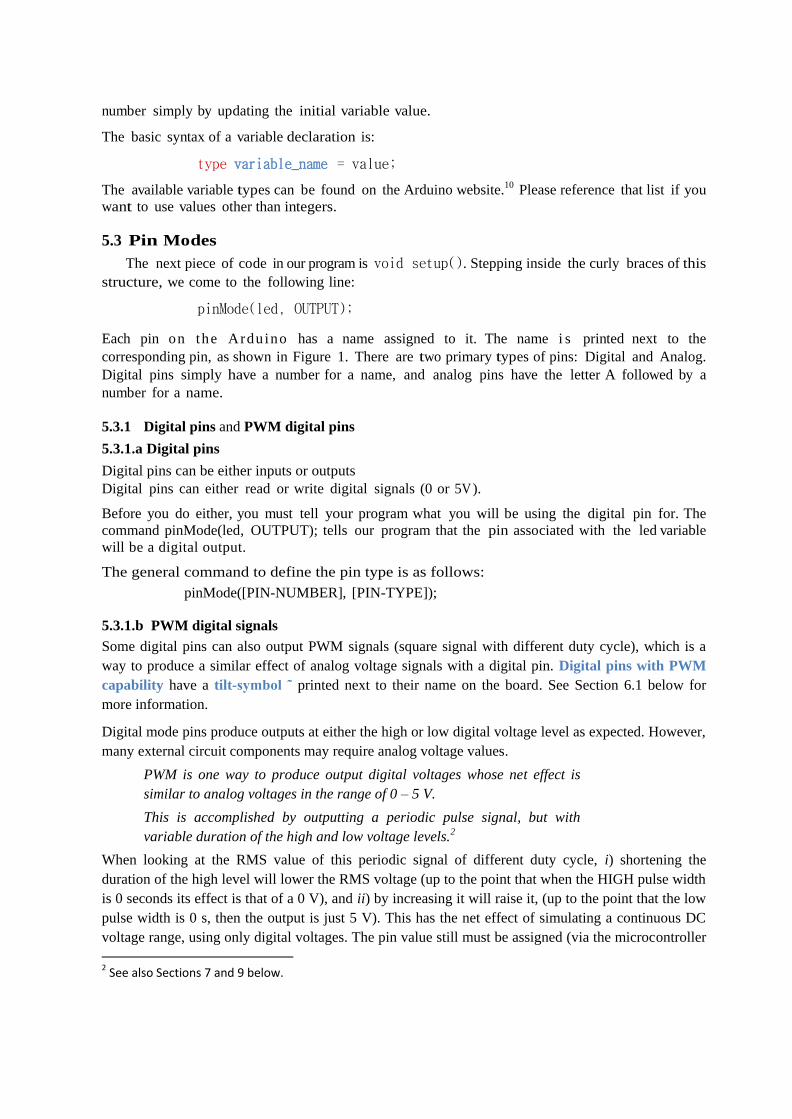
5.3.1.b PWM digital signals
Some digital pins can also output PWM signals (square signal with different duty cycle), which is a
way to produce a similar effect of analog voltage signals with a digital pin. Digital pins with PWM
capability have a tilt-symbol ˜ printed next to their name on the board. See Section 6.1 below for
more information.
Digital mode pins produce outputs at either the high or low digital voltage level as expected. However,
many external circuit components may require analog voltage values.
PWM is one way to produce output digital voltages whose net effect is
similar to analog voltages in the range of 0 – 5 V.
This is accomplished by outputting a periodic pulse signal, but with
variable duration of the high and low voltage levels.2
When looking at the RMS value of this periodic signal of different duty cycle, i) shortening the
duration of the high level will lower the RMS voltage (up to the point that when the HIGH pulse width
is 0 seconds its effect is that of a 0 V), and ii) by increasing it will raise it, (up to the point that the low
pulse width is 0 s, then the output is just 5 V). This has the net effect of simulating a continuous DC
voltage range, using only digital voltages. The pin value still must be assigned (via the microcontroller
2 See also Sections 7 and 9 below.

software) in discrete steps between 0 and 255 (28 different values), giving possible output voltages that
differ by steps of,
Veq = 5 V/ 255
(More about “PWM output” is addressed in Section 7 below).
5.3.2 Analog pins
Analog Pins can read in analog voltages between 0V and 5V,
The Arduino has inside an analog-to-digital converter circuit that reads this voltage and converts it to
a single 10-bit value (a number between 0 and 1023). H e r e 0 represents 0V, and 1024 represents 5 V.
This 10-bit value is what the software sees as the input on that pin.
The discrete values of the input and output pins are a limitation of the microcontroller when working
with external systems that expect continuous values, such as LED - photoresistor system regulated in
this experiment.
Analog pins do not need a pin mode set before reading within your program.
Available pin modes can be found at the Arduino website.11
5.4 Generating an output
Once the pin mode is set, the program exit the void setup() and enters the void loop(), the
part of the program that will run over and over in an infinite loop.
The first command to execute is,
digitalWrite(led, HIGH);
The command digitalWrite([PIN],[VALUE]) lets us set the output value of a digital pin that
has been set to an OUTPUT type. In this case, we write a value of HIGH, or 5V, to the pin
referred to by the led variable. A value of LOW would refer to 0V.
Next the program tells the Arduino to wait for a g i v e n period, before executing the next line of
code. This period is equal to 1000 ms.
delay(1000);
After waiting for 1000 ms, the code writes a value of LOW to the led pin, and then makes it wait
for 2000 ms.
digitalWrite(led, LOW);
delay(2000);
At this point, there is no more code left in our program, so it starts executing void loop() again.
Congratulations, you now should have some basic understanding of how an Arduino program
is written.
6. MODIFYING the BLINK PROGRAM
Now you will try your hand at modifying the blink program. What we are going to do is
define a new variable called wait, give it a value, and then replace the delay time on the Arduino
with our new variable.

6.1 Create a new variable
Right below the led variable declaration, add a new variable named wait of type int and assign
a reasonable value different than 1000 (like 100). Add also a comment describing what this
variable is used for.
6.2 Use your new variable
We want to use this new variable to declare the time we wait in between turning our LED on and
off. Go ahead and replace the old delay values with your new variable name.
6.3 Verify and upload your modified program
The Arduino should still be set up from when you first uploaded the first blink program. Verify
your new program to see if it compiles. If you get an error, check your work for syntax error. Did
you forget a semicolon or a brace?
Once your program verifies, and you are able to upload it to your board, you should start to see
your LED blink faster or slower, depending on the value you defined your variable. _____________________________________________________________________________________
1 int led = 13;
2 int wait = 100; // Time to wait before blinking 3
4 void setup()
5 pinMode(led, OUTPUT);
6 7
8 void loop()
9 digitalWrite(led, HIGH);
10 delay(wait); //Wait for the amount declared in the wait variable
11 digitalWrite(led, LOW);
12 delay(wait); //Wait for the amount declared in the wait variable
13 ____________________________________________________________________________________
Figure 6: The modified Blink Program
6.4 Final modification
Once you make your modification, you will have code that looks similar to Figure 6.
7 . USING INPUTS to CONTROL OUTPUTS
7.1 Understanding PWM
Arduino cannot output true analog signals. One way to output a digital signal that reflects the
value of an analog signal is pulse-width-modulation (PWM) Compared to a square signal, where the
duty cycle is 50% (half of the period HIGH and half of the period LOW), the PWM signal has a duty
cycle in which the time during which the signal remains HIGH is proportional to the analog signal (see
Section 9 below).
Accordingly, when driving an LED with a PWM signal, one is able to vary the brightness of the LED

by writing on the PWM pin a proper (digital) value. Actually, an analog signal should be first read by
the Arduino (which converts it to a value between 0 and 1023) and then one has to convert that value
into an 8 bit (0 to 255 range) number; the latter is used to write the PWM pin. The net result is that
you can generate digital signals (switching on and off) that have similar effects as analog signals.
7.1.1 Observing PWM signals
Load the 01.Basic → Fade example program and upload it to your Arduino board (a modified
version of the program is shown in Fig. 8 below). Wire up the LED to the pin that is used in the
program; if it is a digital pin other than pin 13, you will need to add a 330 Ω resistor in series with the
LED. If you increase the delay time to 80, you should be able to observe the PWM flicker at lower
brightness levels. You can leave the LED in place. Observe how the signal looks like on your
oscilloscope.
7.2 Controlling the PWM output with a potentiometer
We will control the the PWM signal (i.e. we will control the duty cycle of the square signal) by
reading the voltage from a potentiometer lead connected to the analog input A0.
PWM
5V
GND
10 k D9
D8
D10
A0
A1
LED
330
Analog
input
Figure 7: Potentiometer and LED wired up to the Arduino. Pin 9 is a PWM output.
Hook up a 10k potentiometer between the 5V and ground and the middle leg to the A0

analog input on your Arduino as seen in Figure 7. Modify your Fade code from Section
7.1.1 to the code shown in Figure 8.
7.2.1 Understanding the changes made to the Fade program
We have modified the original Fade program to, instead, control the LED brightness with a
potentiometer.
In the new program we have declared a few new variables to keep track of an analog input pin,
the variables used for storing values from our analog input readings, and our PWM output values.
See the comments in the code for more context.
Establishing serial communication
In the void setup() loop we use
Serial.begin(9600);
to begin serial communications, at 9600 bits of data per second, between the Arduino and the
computer (remember how we picked a serial port in Section 3.4).
Outputting data to the serial line is a nice way to see (on the computer screen) what is going on in your
code while it is running. But remember that your program will run no faster than the speed of your
serial line.
Reading the analog signal from the potentiometer
The next new piece of code is
analogRead(pot);
It reads the analog input (0-5V range) on pin pot (in the program this pin has been declared as pin A0)
and converts it to a discrete value between 0 and 1023 (210 discrete values range.)12
(Recall the Arduino has inside an analog-to-digital converter circuit that reads this voltage and
converts it to a number between 0 and 1023).
Controlling the PMW
Pin led (declared as pin 9 in the program) only outputs PWM values ( i.e. square wave with
different duty cycles).
First, we have to solve the following issue:
On one hand, the PWM can be controlled only by an 8 bit digital number (that is,
one needs to write a value between 0 and 255 to the led pin).
On the other hand, in our current experiment we have a number between 0 and
1023 read from the analog pin pot.
We need to make a corresponding conversion then.
One alternative is to use the command called map() which handles the analog-input-range to the
PWM-output-range conversion. Its syntax is,
map (valuetoscale, fromLow, fromHigh, toLow, toHigh)
In our program we use,
outputValue = map(sensorValue, 0, 1023, 0, 255);
/* Map sensorValue to 8 bits (0 to 255) */
See the map info page for more details.13

Next we write the adjusted input value to our led pin using,
analogWrite(led, outputValue);
Displaying the input and output voltages
Finally we print these input and output values the the serial line using the command,
Serial.print(value);
Open the serial monitor now to view these values in real time. Go to Tools→ Serial Monitor .
You should see the input and output values similar to Figure 9. ____________________________________________________________________________________________________________________________
1 const int led = 9; // the PWM pin where the LED is attached to
2 const int pot = A0; // A0 will be the analog input channel
3 int sensorValue = 0; // sensorValue will store the value read from the pot
4 int outputValue = 0; // this is the value sent to the PWM pin 5
6 void setup()
7 pinMode(led, OUTPUT); // declare the PWM pin 9 to be an output
8 Serial.begin(9600); // Open a serial monitor at 9600 baud
9
10 void loop()
11 sensorValue = analogRead(pot); // store pot value in sensorValue
12 outputValue = map(sensorValue, 0, 1023, 0, 255); // map sensorValue to a 8 bit number (0 to 255)
13 analogWrite(led, outputValue); // write the analog out value to pin led: 14
15 Serial.print("sensor = " ); // print the results to the serial monitor:
16 Serial.print(sensorValue);
17 Serial.print("\t output = ");
18 Serial.println(outputValue); 19
20 delay(2); // wait 2 milliseconds for daq to settle
21 ___________________________________________________________________________________________________________________________
Figure 8: The Fade program modified to control the LED with a potentiometer.

Figure 9: The serial monitor in action.
7.3 Photo Resistor
Remove the potentiometer and wire in a photo-resistor as seen in Figure 10. A photo-resistor
has a variable resistance depending on how much light is incident on it.14
10 k Photoresistor
330 LED
GND 5V
A0
PWM
D9
Figure 10: Photo-resistor connected to the analog input A0.
Using the same code as in Section 7.2, observe the output of the photo resistor and the PWM
output on pin 9 simultaneously on your oscilloscope. Vary the amount of light incident on the
photo-resistor and observe and compare the PWM output and analog voltage across the photo-
resistor.

Check also what happens, upon light incident on the photoresistor, when you interchange the position
of the photoresistor with the 10 k resistor in the circuit. If there is any difference, explain why.
7.4 Arduino Thermostat
We will now use a TMP36 temperature sensor as an analog input to read in temperature data,
and control an LED to indicate we have reached a particular temperature. The TMP36 provides
an accurate, linear representation of temperature between the range of −40 C and +125 C
using the factor of 10 mV/oC.15
See the data sheet for more information.16 Hook up the circuit
shown in Figure 11.
For our code, we will,
a) read the potentiometer as an analog input and use its position as a threshold value.
b) read the current temperature indicated by the thermostat
c) compare the threshold value to the temperature value.
If the temperature is above the threshold, the LED will turn on, and if it is below, it will turn off.
We will also be monitoring the values using the serial monitor so we can tell what is going on. See if
you can write this program on your own, or look at Figure 12.
7.4.1 Testing the Thermostat
Upload your program and open the the serial monitor. You should see a value from your
TMP36 as well as your potentiometer and the state of the LED. Adjust the pot to where the LED
turns on, with the threshold below the temperature value. Then try setting the threshold above the
current temperature and confirm that the LED turns off.
Now, set the threshold a few integer values above the current temperature value. Confirm that it turns
on. DO NOT touch the temperature sensor with your fingers; if its pins are placed wrong in the
circuit, the device will be very hot and could blister your fingers!
GND
330 LED
VS
VOUT
GND
10 k
D9
A1
Bottom View: The legs of the device should be pointing towards you when reading this pin identification
A0
5V
PWM
Figure 11: L e f t : Circuit for comparing the voltage set by the potentiometer (analog signal
read at A0 ) and the output from the thermostat (analog signal read at A1 ). Right: TMP36
pinout.
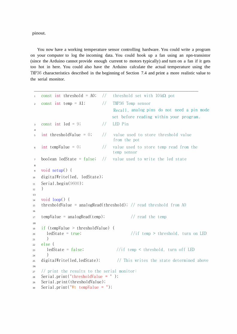
You now have a working temperature sensor controlling hardware. You could write a program
on your computer to log the incoming data. You could hook up a fan using an npn-transistor
(since the Arduino cannot provide enough current to motors typically) and turn on a fan if it gets
too hot in here. You could also have the Arduino calculate the actual temperature using the
TMP36 characteristics described in the beginning of Section 7.4 and print a more realistic value to
the serial monitor.
_________________________________________________________________________
1 const int threshold = A0; // threshold set with 10 k pot
2 const int temp = A1; // TMP36 Temp sensor
Recall, analog pins do not need a pin mode
set before reading within your program.
3 const int led = 9; // LED Pin
4
5 int thresholdValue = 0; // value used to store threshold value from the pot
6 int tempValue = 0; // value used to store temp read from the temp sensor
7 boolean ledState = false; // value used to write the led state
8
9 void setup()
10 digitalWrite(led, ledState);
11 Serial.begin(9600);
12
13
14 void loop()
15 thresholdValue = analogRead(threshold); // read threshold from AO
16
17 tempValue = analogRead(temp); // read the temp
18
19 if (tempValue > thresholdValue)
20 ledState = true; //if temp > threshold, turn on LED
21
22 else
23 ledState = false; //if temp < threshold, turn off LED
24
25 digitalWrite(led,ledState); // This writes the state determined above
26
27 // print the results to the serial monitor:
28 Serial.print("thresholdValue = " );
29 Serial.print(thresholdValue);
30 Serial.print("\t tempValue = ");
31 Serial.print(tempValue);
32 Serial.print("\t LED on?: ");
33 Serial.println(ledState);
34
35 delay(2); //Small settle delay for ADC
36 _________________________________________________________________________
Figure 12: Arduino Thermostat Program.
SECTION I.B
8. Communicating with other devices over the serial line
Objective: We shall attempt having the Arduino communicate with an external program running
on our computer.
For this task we will use Processing, since it integrates well with Arduino and has similar code syntax,
but you could do this using any other programming language such as Python or LabVIEW.
While we have already talked to the Arduino using our computer and the handy serial monitor, here
we will write a program that interfaces with the Arduino directly over the serial line.
8.1 Downloading and installing Processing.
8.1.1 Short version
1. The 'Processing' Libraries are located at the Arduino 'Playground' website here:
http://playground.arduino.cc/Interfacing/Processing#.UyIPEtt38Yw
2. Go to the link above and follow the instructions on the website for installing the 'Processing'
libraries on your computer.
3. The actual program is located here: http://processing.org/
4. Again, follow the instructions on the website to install 'Processing.'
5. Run processing in order to confirm it installed correctly.
8.1.2 Detailed version
Download Processing from the following address. Choose either 64 bit or 32 bit based on your
computer.
https://processing.org/download/
Unzip the zip file to the desktop. The Processing.exe program can be run from within the folder or a
shortcut can be placed wherever you choose.
Now download the Arduino library for Processing (version 2.0 for new processing downloads) from
the Arduino Playground at the following address.
http://playground.arduino.cc/Interfacing/Processing
Open the zip file and copy the folder named “arduino” into your Processing library folder, found in
your documents. Example “C:\Users\username\Documents\Processing\libraries”.

From here, open the Arduino IDE and the Processing IDE. They will appear very similar once opened.
Arduino will be green and Processing will be black. In the Arduino IDE, open the Standard Firmata
sketch by navigating
Toolbar > File > Examples > Firmata > StandardFirmata
and upload it to the Arduino board.
In Processing, go to Toolbar >File > Open, and navigate to one of the Arduino examples found in
C:\Users\username\Documents\Processing\libraries\arduino\examples
(Choose any of the examples files in that folder).
Find the following line of code in Processing: arduino = new Arduino(this, Arduino.list()[0], 57600);
You may need to edit the code to have Processing select the correct serial port used by Arduino.
Specifically, change the [0] in this line. To find the correct number, run this code in Processing:
import processing.serial.*;
import cc.arduino.*;
println(Arduino.list());
The correct value for [0] will be given to you. Finally, run the program. Now you are ready to run any
Arduino program in Processing.
8.2 Sending Data to an External Program
This example is based off of the “Graph example program” found in,
File → Examples → 04. Communication → Graph
We can use the same circuit as above, as all we are doing is sending the potentiometer signal out
of the serial line again.
Go ahead and upload this program to your Arduino and make sure it runs by watching the serial
bus.
8.2.1 Steps to set up the 'Graph' program (Getting “Graph’ in Processing-code)
1. Run the Arduino IDE.
2. Open 'Graph' located in the dropdown menu,
'Open 04.Communication Graph' or
'File Open examples 04.Communication Graph Graph.ino'.
3. About halfway down the program there is a line that looks like this:
/* Processing code for this example
4. Copy all the code below this line and above the block of gibberish and paste it into a new
'Processing' sketch.
5. Uncomment the code by deleting all the '/*' and the '*/' at the start and end of the copied
section of the code. (Everything between these is commented out).
6. Once those are deleted, the code should change color to confirm it is no longer commented.
7. Compile the code now, if it compiles correctly, 'Processing' should be able to run the 'Graph'
program.

Steps for running the program:
1. Ensure 'Serial Monitor' is not running, processing cannot read the serial port if another
program is reading from it.
2. Start the 'Graph' program in 'Processing'.
You should see a window with a black background and a yellow output signal. This signal is
being read from the potentiometer and its amplitude will vary as the potentiometer is
adjusted.
3. If you do not see this graph, double check the serial port settings in 'Processing,' it will be a
little different than the Arduino IDE and may take a little bit more effort to get working.
4. The serial port on 'Processing' is set to '0' by default, try incrementing the value by '1' and try
again; repeat as necessary.
5. Note: You can stop 'Processing' and start 'Serial Monitor' from IDE in order to get a numerical
representation of what signal is getting sent from the potentiometer.
The following graphic is a rough example of the flow of data in this setup:
The Arduino IDE program transmits the code you used in section 7 to the Arduino over the serial
port.
The Arduino saves the code and starts running the program by sending inputs through the circuit
and looking at the output signals it receives.
The Arduino then sends the output signal to the computer across the serial cable and any program
on the computer can now look at that information but only one-at-a-time can look at it. (If the
Arduino IDE is running the 'Serial Monitor' program, it will block any other program from looking
at it. Same goes for the 'Processing' program. Basically it is a first-come-first-serve basis to see
which program gets to look at the serial port.)
If you did everything right, when you launch the Processing sketch, it should start plotting the value
being read in from the potentiometer value. Processing is running a graph application.
In short, using a program wrote in Processing code (it could have been a code written in LabView), we
are graphing a value provided by the the Arduino (value sent over the serial port).
You may have to futz around with the serial port selection on the processing sketch. Now is your
chance to troubleshoot!
8.3 Sending commands to the Arduino externally In this example, we will be exploring two new concepts:
i) The case structure, and
i i ) Setting up the Arduino to respond to messages sent to it by a computer over the serial port.
Note that these messages could conceivably come from any other device or program that can
talk over a serial line. We will be able to send a command over the serial monitor and turn a
specific LED on or off.
8.3.1 Wire up some LEDs
Wire up two LEDs to two separate digital pin channels as see in Figure 13.
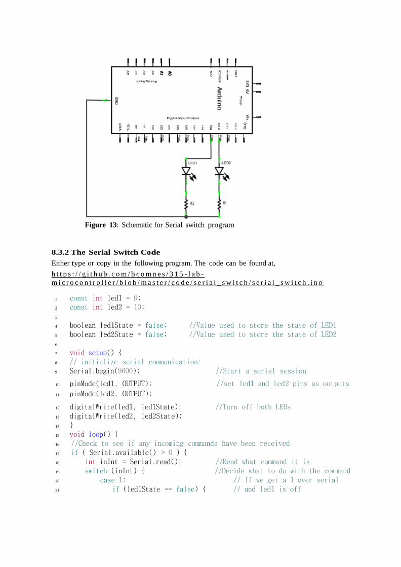
Figure 13: Schematic for Serial switch program
8.3.2 The Serial Switch Code
Either type or copy in the following program. The code can be found at,
h t t p s : / / g i t h u b . c o m / b c o m n e s / 3 1 5 - l a b -
m i c r o c o n t r o l l e r / b l o b / m a s t e r / c o d e / s e r i a l _ s w i t c h / s e r i a l _ s w i t c h . i n o
1 const int led1 = 9;
2 const int led2 = 10;
3
4 boolean led1State = false; //Value used to store the state of LED1
5 boolean led2State = false; //Value used to store the state of LED2
6
7 void setup()
8 // initialize serial communication:
9 Serial.begin(9600); //Start a serial session
10 pinMode(led1, OUTPUT); //set led1 and led2 pins as outputs
11 pinMode(led2, OUTPUT);
12 digitalWrite(led1, led1State); //Turn off both LEDs
13 digitalWrite(led2, led2State);
14
15 void loop()
16 //Check to see if any incoming commands have been received
17 if ( Serial.available() > 0 )
18 int inInt = Serial.read(); //Read what command it is
19 switch (inInt) //Decide what to do with the command
20 case 1: // If we get a 1 over serial
21 if (led1State == false) // and led1 is off

22 led1State = true; // set its state to on
23 Serial.println("LED1 ON"); // and let us know
24
25 else
26 led1State = false; //or if led1 is on turn it off
27 Serial.println("LED1 OFF"); //tell us that its turning off
28
29 digitalWrite(led1, led1State); //and update its actual state
30 break; //end case 1
31 case 2: //if we get an incoming 2
32 if (led2State == false) //and if led2 is off
33 led2State = true; //set its state to on
34 Serial.println("LED2 ON"); // let us know
35
36 else //or if its already on
37 led2State = false; //set its state to off
38 Serial.println("LED1 OFF"); //and let us know
39
40 digitalWrite(led2, led2State); //update its actual state
41 break; // end case 2
42 case 0: // if someone sends us a 0
43 led1State = false; // turn off both leds
44 led2State = false;
45 digitalWrite(led1, led1State);
46 digitalWrite(led2, led2State);
47 Serial.println("LEDS OFF"); //and let us know
48 break; //end case 0
49 default:
50 Serial.println(Serial.read()); //if we get something else just print it
51
52
53
Literally we will be entering the keyboard keys 0, 1
8.4 Running the switch
Verify that it compiles and upload the program to your Arduino. Open the serial monitor and type in
‘1’ and press send.LED 1 should turn on. Try sending ‘2 now’. Now send ‘0’. Your Arduino is now
responding to input during runtime!
9. Pulse-width Modulation
The objective is to measure, in a digital format, the analog voltage output from a
sensor device.
Use the op amp LM358AP to compare two input volages:

a) the sensor voltage Vsensor, and
b) a sawthooth voltage of constant frequency (try 100 Hz).
We will mimic the sensor voltage by providing a manually-variable voltage (0 to 5 V range.)
-
+
Vout
Vsensor
+12V
VC
A
Sensor
voltage
Voltage
comparator
5 Volts sawtooth
(100 Hz)
LM358AP
Fig. 9.1 Left: Comparator circuit. Right: Pin connections of the LM358AP. Notice
that a ground terminal replaces –VCC.
Notice in Fig. 9.1 that a ground terminal replaces the rail voltage –VCC.
Monitor in the oscilloscope both, the sawtooth input voltage (channel-1) and the output voltage
(channel-2.)
Figure 9.2 shows the expected signal corresponding to two different “sensor” voltages. Verify if your
set up works as expected.
Notice in Fig. 9.2 that high
sensor
T
V
T
V
0
max . That is,
sensorhigh VV
TT
max
0
where highT is the time the output voltage remain the high level.
0T is the period of the sawtooth input signal
The pulse-width modulator then convert the analog voltage sensor to an output that is
digital in nature (high or low); the time during which the output is high is proportional to
the voltage sensor.

VC (t)
T0 2T0 time
4
3
2
1
T0 2T0
t(ms)
VCC
Vmax
Vout
Thigh
Vsensor
HIGH
LOW
VC (Volts)
T0 2T0 time
4
3
2
1
T0 2T0
t(ms)
VCC
Vmax
Vout
Thigh
Vsensor
HIGH
LOW
Notice the correlation between the magnitude of the analog voltage Vsensor, and
the time during which the output digital signal is in the HIGH state.
Fig. 9.2 Left: Signals corresponding to a relatively low value of Vsensor. Right: Signals
corresponding to a higher Vsensor signal. In both figures, Thigh stands for the interval of time
during which the output voltage stays in the high digital level. Notice the higher the sensor-
voltage Vsensor, the longer the time Thigh the output voltage stays in the high level. To is the
period of the sawtooth signal Vc.
Implementation:
a) Use the op amp LM358AP to implement the comparator circuit shown in Fig. 9.1.
Initially, use a sawtooth voltage of 100 Hz.
b) Verify that the circuit works as advertised in Fig. 9.2
c) Increase gradually the frequency of the sawtooth signal, and estimate the bandwidth of the device.
Some project ideas.
1. Arduino Web Switch : Turn your kettle ON via Internet ...
http://www.hobbyist.co.nz/?q=web-switch-tutorial
2. An easy way to control your Arduino from Internet
http://www.instructables.com/id/An-easy-way-to-control-your-Arduino-from-
Internet-/
REFERENCES
[1] Tmp35/tmp36/tmp37 low voltage temperature sensors. http://dlnmh9ip6v2uc. cloudfront.net/datasheets/Sensors/Temp/TMP35_36_37.pdf.
[2] Arduino.cc. Arduino leonardo. http://arduino.cc/en/Main/ArduinoBoardLeonardo,
2013.
[3] Arduino.cc. Arduino software download. http://arduino.cc/en/Main/Software, 2013.
[4] Arduino.cc. Arduino uno. http://arduino.cc/en/Main/ArduinoBoardUno, 2013.

[5] Arduino.cc. Introduction. http://arduino.cc/en/Guide/Introduction,
2013.
[6] Arduino.cc. map(). http://arduino.cc/en/Reference/Map, 2013.
[7] Arduino.cc. Pinmode(). http://arduino.cc/en/Reference/PinMode, 2013.
[8] Arduino.cc. Reference page. http://arduino.cc/en/Reference/HomePage, 2013.
[9] Marshal Colville. Process control with a microcontroller pwm output, pid control, and
hardware implementation. 2012.
[10] processing.org. Processing programming language. http://processing.org/, 2013.
[11] SparkFun. Tmp36 - temperature sensor. https://www.sparkfun.com/products/10988,
2013.
[12] Wikipedia. Pulse-width modulation. http://en.wikipedia.org/wiki/Pulse-
width_modulation, 2013.
[13] Wikipedia. Microcontroller. http://en.wikipedia.org/wiki/Microcontroller,
2013.
[14] Wikipedia. Pid controller. http://en.wikipedia.org/wiki/PID_controller, 2013.
[15] Wikipedia. Surface-mount technology. http://en.wikipedia.org/wiki/Surface-
mount_technology, 2013.
[16] Wikipedia. Through-hole technology. http://en.wikipedia.org/wiki/Through-
hole_technology, 2013.
[17] http://arduino.cc/en/Tutorial/ReadAnalogVoltage
[18] Connecting a phoresistor http://www.acroname.com/howto/photoresistor/photoresistor.html
1 Wikipedia. Microcontroller. http://en.wikipedia.org/wiki/Microcontroller, 2013. 2 Arduino.cc. Arduino leonardo. http://arduino.cc/en/Main/ArduinoBoardLeonardo, 2013. 3 Arduino.cc. Arduino uno. http://arduino.cc/en/Main/ArduinoBoardUno, 2013. 4 Wikipedia. Surface-mount technology. http://en.wikipedia.org/wiki/Surface-mount_technology,
2013. 5 Wikipedia. Through-hole technology. http://en.wikipedia.org/wiki/Through-hole_technology,
2013. 6 Processing programming language. http://processing.org/, 2013. 7 http://hello.processing.org/editor/ 8 Arduino.cc. Introduction. http://arduino.cc/en/Guide/Introduction, 2013. 9 Arduino.cc. Arduino software download. http://arduino.cc/en/Main/Software, 2013. 10 Arduino.cc. Reference page. http://arduino.cc/en/Reference/HomePage, 2013. 11 Arduino.cc. Pinmode(). http://arduino.cc/en/Reference/PinMode, 2013. 12 So we get 10-bit reading capabilities with a 8-bit arduino microprocessor. You can find a
description of the trick at https://www.newbiehack.com/MicrocontrollersADC10Bits.aspx 13 Arduino.cc. map(). http://arduino.cc/en/Reference/Map, 2013. 14 Connecting a phoresistor http://www.acroname.com/howto/photoresistor/photoresistor.html 15 SparkFun. Tmp36 - temperature sensor. https://www.sparkfun.com/products/10988, 2013. 16 Tmp35/tmp36/tmp37 low voltage temperature sensors. http://dlnmh9ip6v2uc.
cloudfront.net/datasheets/Sensors/Temp/TMP35_36_37.pdf