introduction to powerworldsimulator: interface and common...
TRANSCRIPT
[email protected]://www.powerworld.com
2001 South First StreetChampaign, Illinois 61820+1 (217) 384.6330
2001 South First StreetChampaign, Illinois 61820+1 (217) 384.6330
Introduction to PowerWorld Simulator: Interface and Common Tools
I1: The PowerWorld Simulator Case Editor

2© 2014 PowerWorld CorporationI1: Simulator Case Editor
Background

3© 2014 PowerWorld CorporationI1: Simulator Case Editor
• User‐friendly and highly interactive power system analysis and visualization platform.
• Integrates many commonly performed power system tasks– Contingency Analysis, Time‐Step Simulation, OPF, ATC, PVQV, Fault Analysis, SCOPF, Sensitivity Analysis, Loss Analysis, Transient Stability, GIC
• Designed to operate on Microsoft Windows XP/2003/Vista/2008/7/8 platforms
PowerWorld Simulator
4© 2014 PowerWorld CorporationI1: Simulator Case Editor
• Version 1.0 created in May 1994 at the University of Illinois Urbana‐Champaign by Professor Thomas Overbye (Ph.D.)
• Impetus for early versions was to teach power system operation to non‐technical audiences.
PowerWorld Simulator History
5© 2014 PowerWorld CorporationI1: Simulator Case Editor
• PowerWorld Corporation was formed in 1996 with the goal of further developing and commercializing the Simulator tool.
• Simulator version 18:– Virtually unrecognizable from the early versions of the software.
– Has evolved into a powerful power system analysis and visualization environment capable of solving very large systems.
PowerWorld Simulator History
6© 2014 PowerWorld CorporationI1: Simulator Case Editor
• Provide a better understanding of how to use PowerWorld Simulator for power system analysis and visualization.
• Provide techniques for building good power system models and show how these techniques can be used to analyze system issues.
Training Goals

7© 2014 PowerWorld CorporationI1: Simulator Case Editor
• Primary Goal: Make you aware of the capabilities of Simulator– We are frequently asked to add features to Simulator that are already available.
– We want you to make the most of our software.
Training Goals

8© 2014 PowerWorld CorporationI1: Simulator Case Editor
The PowerWorld Simulator Case Editor
9© 2014 PowerWorld CorporationI1: Simulator Case Editor
• Simulator seamlessly integrates two functions once commonly separated in power flow software:– Graphical power system case editor– Power Flow package with many related analysis tools:
• Contingency Analysis, Time‐Step Simulation, Sensitivity Analysis, Loss Analysis, Fault Analysis, OPF, PVQV, ATC, SCOPF
– Also, Transient Stability and Distributed Computing have recently become available
Overview
10© 2014 PowerWorld CorporationI1: Simulator Case Editor
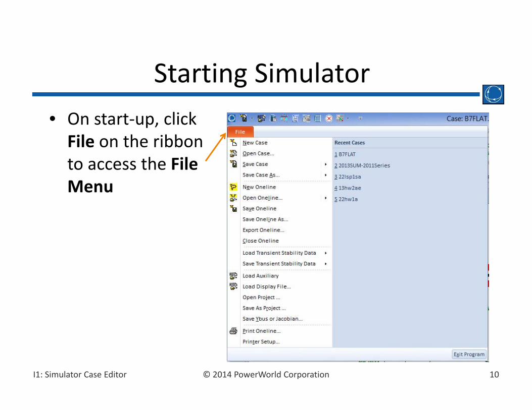
• On start‐up, click File on the ribbon to access the File Menu
Starting Simulator

11© 2014 PowerWorld CorporationI1: Simulator Case Editor
• Menus are integrated in the Ribbon interface
Ribbon Interface
File MenuQuick Access Toolbar
Ribbon Groups
Application Title Bar
Help Button
Ribbon Tabs

12© 2014 PowerWorld CorporationI1: Simulator Case Editor
• Selecting a menu item from the Ribbon reveals a set of task‐specific buttons– Previous Slide shows the Case Information ribbon tab
– Change to the Tools ribbon tab
– Interface is simplified by presenting only the buttons relevant to the selected menu item.
Ribbon Interface
13© 2014 PowerWorld CorporationI1: Simulator Case Editor
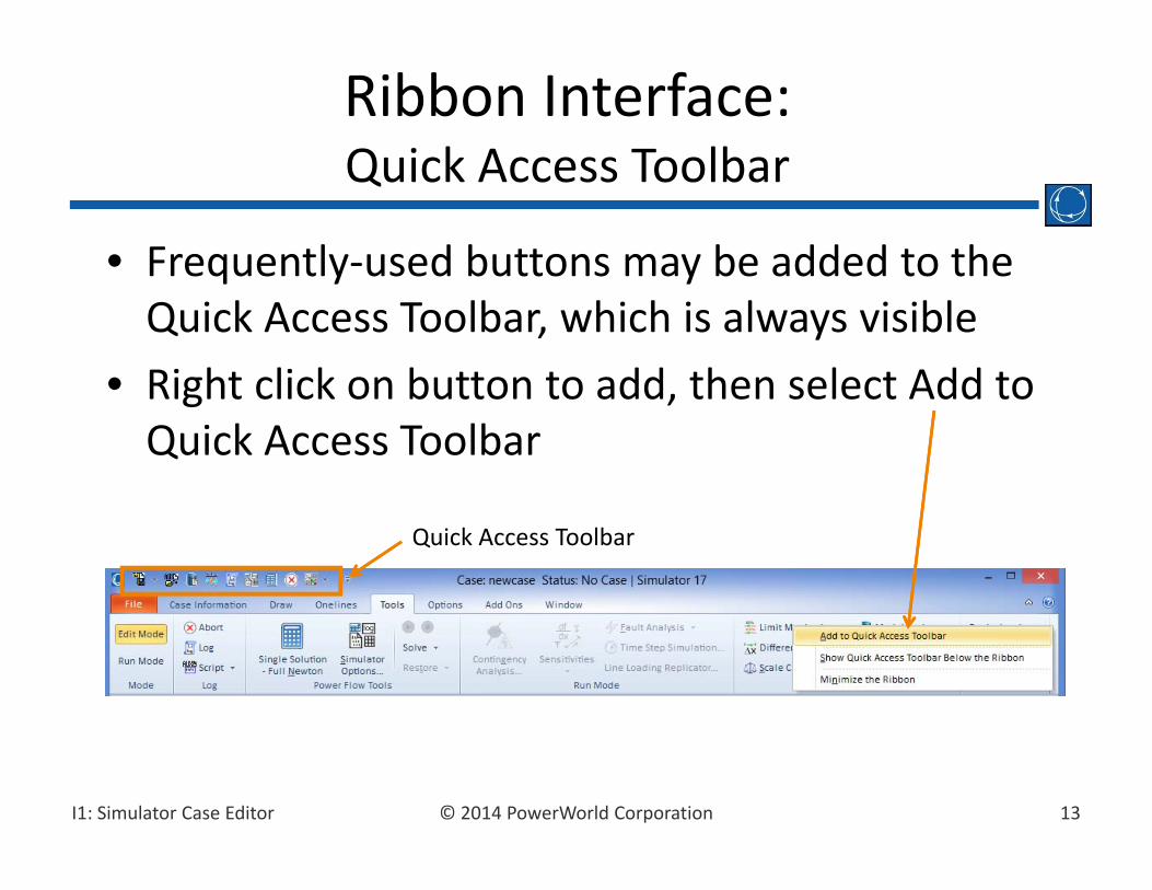
• Frequently‐used buttons may be added to the Quick Access Toolbar, which is always visible
• Right click on button to add, then select Add to Quick Access Toolbar
Ribbon Interface:Quick Access Toolbar
Quick Access Toolbar
14© 2014 PowerWorld CorporationI1: Simulator Case Editor
• The graphical power system case editor and the power flow package are implemented in Simulator’s two distinct modes:– Edit Mode– Run Mode
Modes of Operation
15© 2014 PowerWorld CorporationI1: Simulator Case Editor
• Tasks– Create new power flow cases– Modify existing cases
• Abilities– Cases can be modified either graphically or via text displays
Edit Mode
16© 2014 PowerWorld CorporationI1: Simulator Case Editor
• Stand alone power flow• Power flow analysis tools and sensitivities
– Contingency Analysis– Time‐Step Simulation– Optimal Power Flow (OPF)– PV and QV Curve Tools (PVQV)– Available Transfer Capability (ATC)– Security Constrained OPF (SCOPF)– Sensitivity Analysis– Loss Analysis– Fault Analysis– Transient Stability– Geomagnetically Induced Current (GIC)
Run Mode
17© 2014 PowerWorld CorporationI1: Simulator Case Editor
• Used to create a new case or modify an existing case.
• Use the Ribbon buttons to switch between modes.
• You can switch to Edit Mode at just about any time during a simulation.
• The tools and techniques of Edit Mode will be introduced by creating a new power flow case and by modifying an existing case.
Edit Mode

18© 2014 PowerWorld CorporationI1: Simulator Case Editor
• Click the File Menu, then select New Case.• Mode is automatically switched to Edit.• Prompted to save any existing case.• Display then turns to default onelinebackground color.
• Case may be built by graphically placing objects on the oneline.
Creating a New Case
19© 2014 PowerWorld CorporationI1: Simulator Case Editor
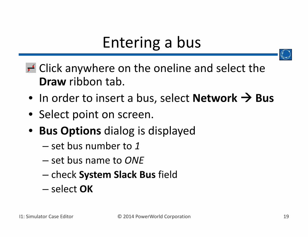
• Click anywhere on the oneline and select the Draw ribbon tab.
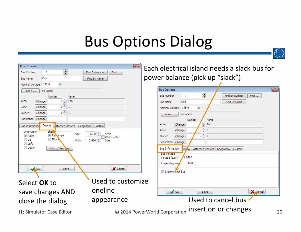
• In order to insert a bus, select Network Bus• Select point on screen.• Bus Options dialog is displayed
– set bus number to 1– set bus name to ONE– check System Slack Bus field– select OK
Entering a bus
20© 2014 PowerWorld CorporationI1: Simulator Case Editor
Bus Options DialogEach electrical island needs a slack bus for power balance (pick up “slack”)
Used to cancel bus insertion or changes
Used to customize onelineappearance
Select OK to save changes AND close the dialog

21© 2014 PowerWorld CorporationI1: Simulator Case Editor
• Select Network Generator from the Draw ribbon tab.
• Click on desired bus.• Generator Options dialog is displayed
– Enter 0 in the MW Output field of the MW and Voltage Control tab
– Make sure Anchored box is checked– Click OK to accept default values of remaining fields
Entering a Generator

22© 2014 PowerWorld CorporationI1: Simulator Case Editor
Generator DialogTerminalbus number and name.
Used tocustomizedisplayappearance
Status
Cost models
Voltage/reactivepower control fields
Rotor shape

23© 2014 PowerWorld CorporationI1: Simulator Case Editor
Oneline Diagram

24© 2014 PowerWorld CorporationI1: Simulator Case Editor
• To save the work done so far, select Save Case, from the File Menu.
• Before case is saved, validation is run to make sure there are no errors.
• Validation results are displayed in Message Logdisplay. To view the message log, click on Logbutton in the Tools ribbon tab
Saving the Case

25© 2014 PowerWorld CorporationI1: Simulator Case Editor
• The power flow case itself is saved using the PowerWorld Binary format (*.pwb).
• The oneline is saved using the PowerWorld Display format (*.pwd).
• Saving the oneline information in a separate file allows using:– Multiple onelines with the same case– A single oneline with different cases
Default Save Case Formats
26© 2014 PowerWorld CorporationI1: Simulator Case Editor
• Again select the Draw ribbon tab, Network BusClick to the right of the bus ONE
• Set bus name to TWO• To model a load, select Attached Devices tab, click Add or Edit Bus Load, set Constant Power MW to 200and Constant Power Mvar to 100.
• Select Network Load to enter a load symbol• Set Orientation to up• Ensure Anchored box is checked
Entering a Second Bus

27© 2014 PowerWorld CorporationI1: Simulator Case Editor
• To reposition bus 1, left‐click on the bus. Then, while holding down the left mouse button, drag the bus to the desired location.– Note that all attached (and anchored) objects move with the bus.
– Individual objects such as generators and loads can be repositioned similarly.
• To reposition the entire oneline, click on the diagram (not on a specific object) and drag.
Moving Oneline Objects

28© 2014 PowerWorld CorporationI1: Simulator Case Editor
• Keyboard shortcuts– Left‐click on and select object(s) to move– Shift‐arrow keys (up, down, left, right) move in small steps– Shift‐Page Up moves object(s) up in larger steps– Shift‐Page Down moves object(s) down in larger steps– Shift‐Home moves object(s) left in larger steps– Shift‐End moves object(s) right in larger steps
Moving Oneline Objects

29© 2014 PowerWorld CorporationI1: Simulator Case Editor
• Pan Up– Up Arrow key– Page Up key pans quickly
• Pan Down– Down Arrow key– Page Down key pans quickly
• Pan Left– Left Arrow key– Home key pans quickly
• Pan Right– Right Arrow key– End key pans quickly
Panning Keyboard Shortcuts
30© 2014 PowerWorld CorporationI1: Simulator Case Editor
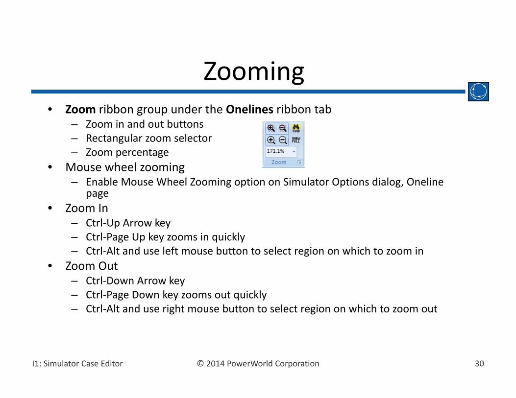
• Zoom ribbon group under the Onelines ribbon tab– Zoom in and out buttons– Rectangular zoom selector– Zoom percentage
• Mouse wheel zooming– Enable Mouse Wheel Zooming option on Simulator Options dialog, Oneline
page• Zoom In
– Ctrl‐Up Arrow key– Ctrl‐Page Up key zooms in quickly– Ctrl‐Alt and use left mouse button to select region on which to zoom in
• Zoom Out– Ctrl‐Down Arrow key– Ctrl‐Page Down key zooms out quickly– Ctrl‐Alt and use right mouse button to select region on which to zoom out
Zooming
31© 2014 PowerWorld CorporationI1: Simulator Case Editor
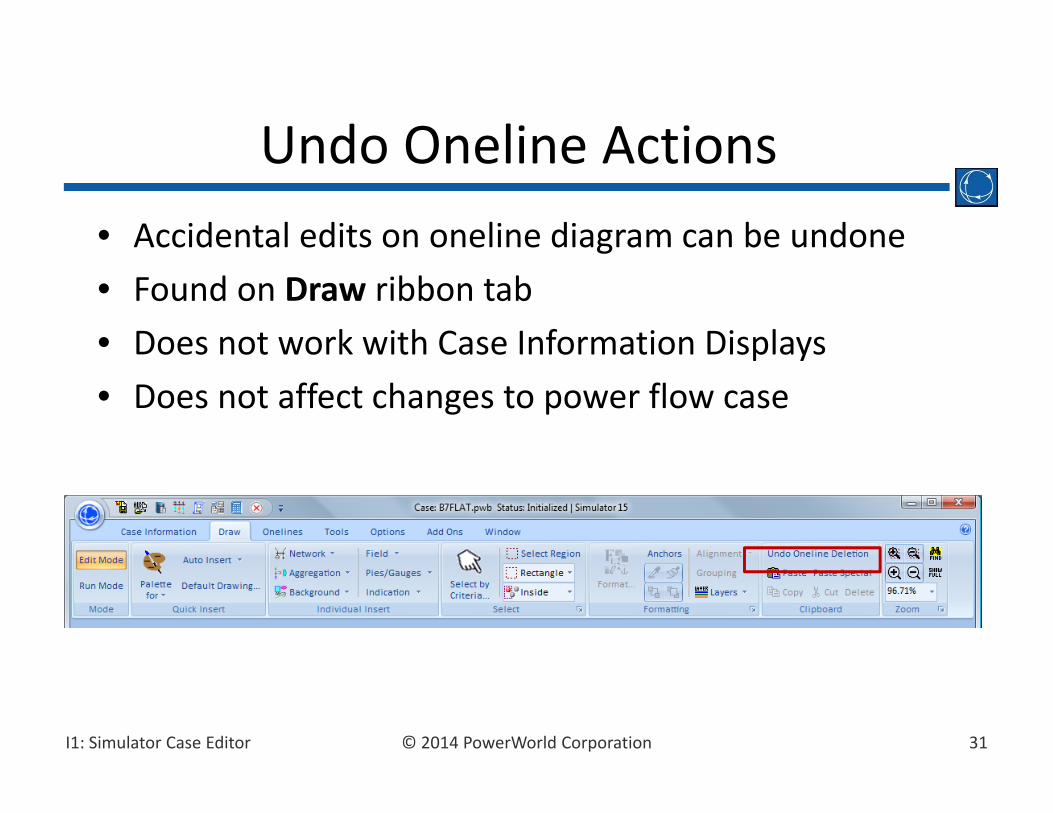
• Accidental edits on oneline diagram can be undone• Found on Draw ribbon tab• Does not work with Case Information Displays• Does not affect changes to power flow case
Undo Oneline Actions
32© 2014 PowerWorld CorporationI1: Simulator Case Editor
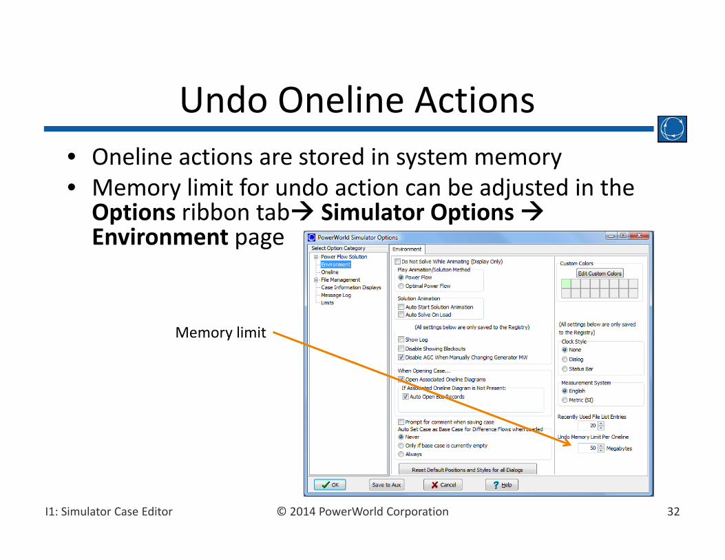
• Oneline actions are stored in system memory• Memory limit for undo action can be adjusted in the Options ribbon tab Simulator OptionsEnvironment page
Undo Oneline Actions
Memory limit
33© 2014 PowerWorld CorporationI1: Simulator Case Editor
• An invisible drawing grid helps align oneline objects. By default, all objects snap to this grid.
• Hold done the ALT key while moving an object to temporarily disable “snap‐to‐grid”.
• To enable/disable the grid:– Select the Options ribbon tab Oneline Display Options
– See Snap Options to Grid field on the Grid/Highlight Unlinked page.
Drawing Grid
34© 2014 PowerWorld CorporationI1: Simulator Case Editor
• Transmission lines are drawn as a series of line segments
• To enter a transmission line between buses 1 and 2– Select the Draw ribbon tab, Network Transmission Line.– Click on bus 1. This begins process of inserting the line.– Move cursor to desired location, then left‐click to enter a segment, double‐click on terminal bus to end.
• Note: Clicking and dragging mouse when drawing transmission lines is usually NOT recommended. This will produce a curved line with many segments.
Entering a Transmission Line
35© 2014 PowerWorld CorporationI1: Simulator Case Editor
• After double‐clicking, Transmission Line/Transformer Options dialog is displayed– From and To Buses and Circuit are set automatically– Set Series Resistance to 0.02– Set Series Reactance to 0.08– Set Shunt Charging to 0.1. – Set Shunt Conductance to 0. – Set Limit A (MVA) rating field to 400.– select OK
Entering a Transmission Line

36© 2014 PowerWorld CorporationI1: Simulator Case Editor
Transmission Line DialogTerminalbuses areusually set
automatically
Simulatorallows eightdifferentlimits
Lineparameters
Line status
37© 2014 PowerWorld CorporationI1: Simulator Case Editor
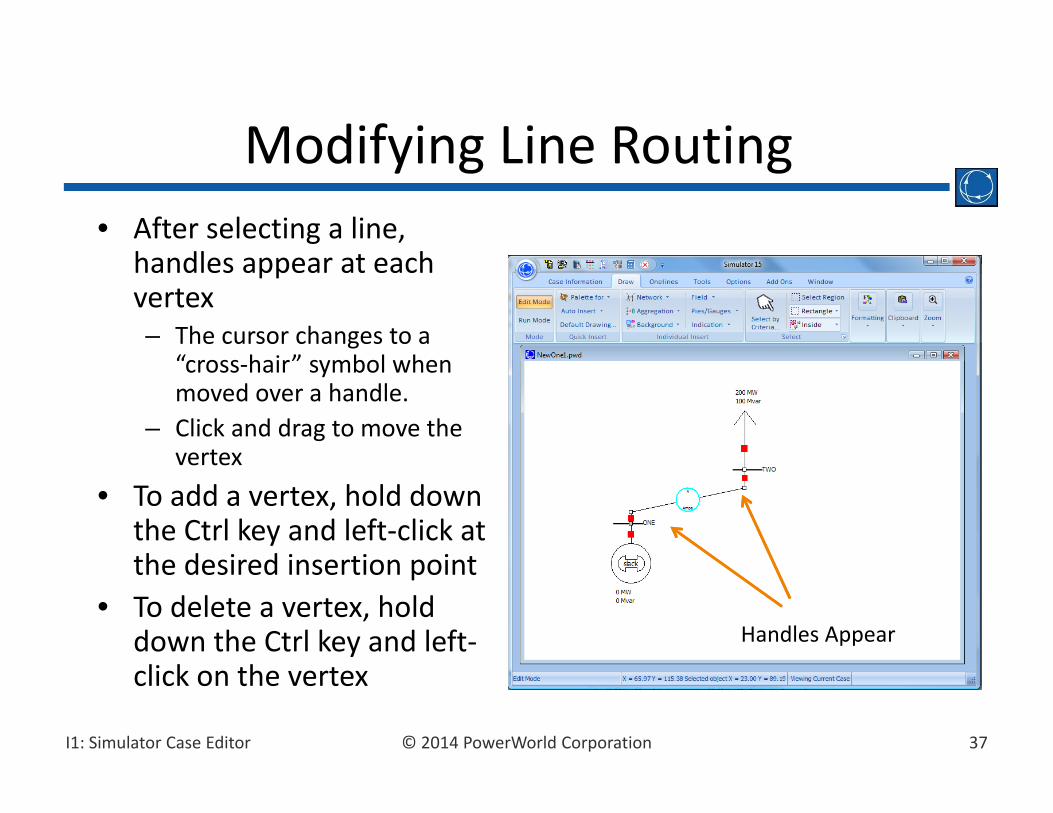
• After selecting a line, handles appear at each vertex– The cursor changes to a
“cross‐hair” symbol when moved over a handle.
– Click and drag to move the vertex
• To add a vertex, hold down the Ctrl key and left‐click at the desired insertion point
• To delete a vertex, hold down the Ctrl key and left‐click on the vertex
Modifying Line Routing
Handles Appear
38© 2014 PowerWorld CorporationI1: Simulator Case Editor
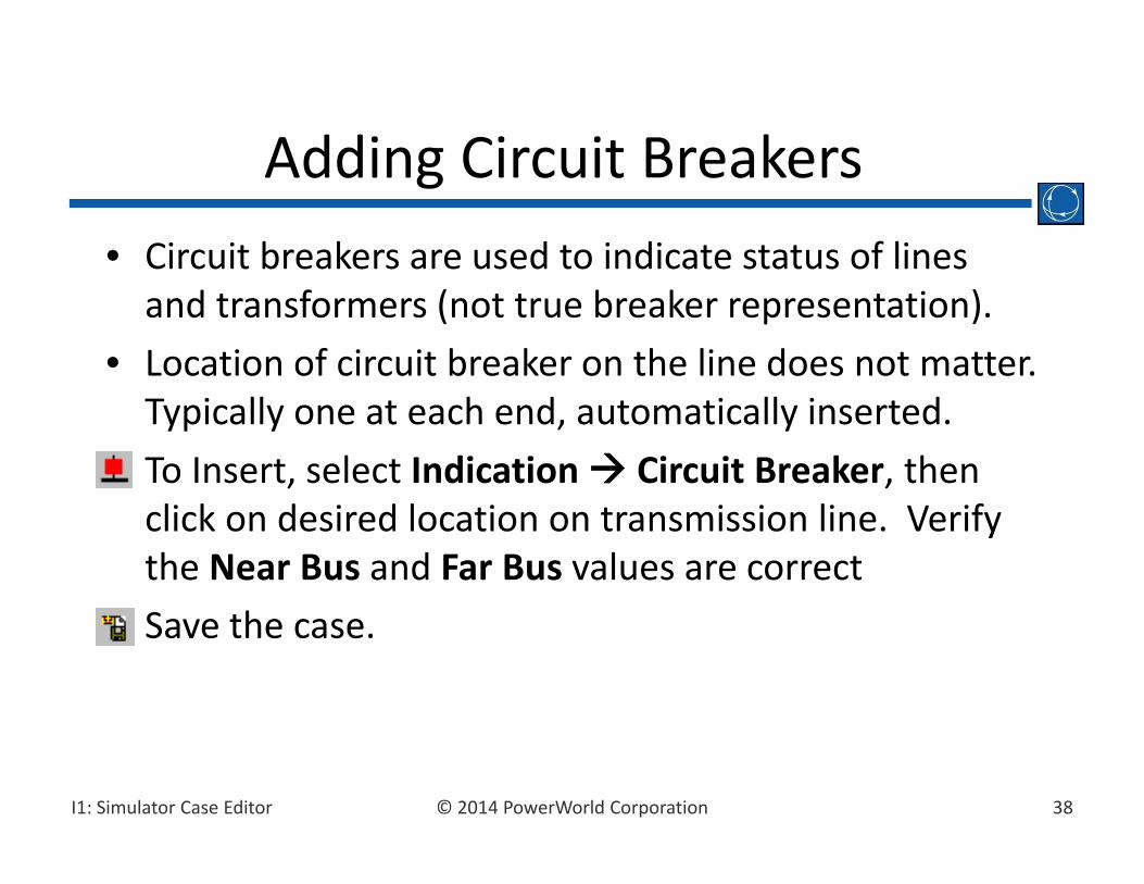
• Circuit breakers are used to indicate status of lines and transformers (not true breaker representation).
• Location of circuit breaker on the line does not matter. Typically one at each end, automatically inserted.
• To Insert, select Indication Circuit Breaker, then click on desired location on transmission line. Verify the Near Bus and Far Bus values are correct
• Save the case.
Adding Circuit Breakers
39© 2014 PowerWorld CorporationI1: Simulator Case Editor
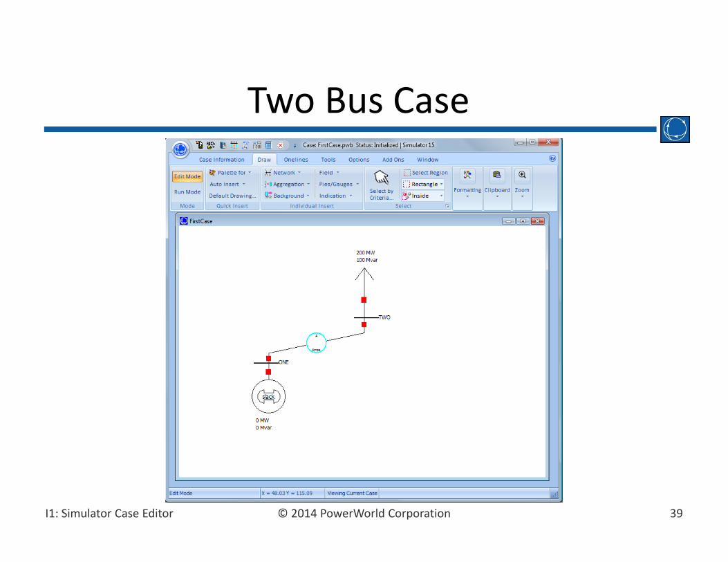
Two Bus Case
40© 2014 PowerWorld CorporationI1: Simulator Case Editor
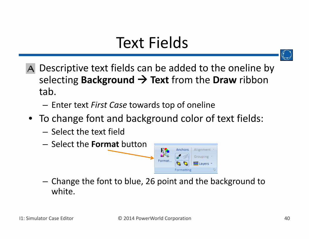
• Descriptive text fields can be added to the oneline by selecting Background Text from the Draw ribbon tab.– Enter text First Case towards top of oneline
• To change font and background color of text fields:– Select the text field– Select the Format button
– Change the font to blue, 26 point and the background to white.
Text Fields

41© 2014 PowerWorld CorporationI1: Simulator Case Editor
• Bus fields show information about bus devices, including loads and generators.
• Fields can be entered automatically, or manually. Choose Field in the Draw ribbon tab.
• Can choose type of field, digits to right and left of decimal, and whether or not it is anchored.
Bus Fields

42© 2014 PowerWorld CorporationI1: Simulator Case Editor
• Line fields show information about transmission lines and transformers.
• For line fields, flow is always specified at an end of the transmission line or transformer.
• End is normally determined automatically by insertion point.
• Just like Text Fields, Bus and Line fields can be formatted using the options in the Formattingribbon group.
Line Fields
43© 2014 PowerWorld CorporationI1: Simulator Case Editor
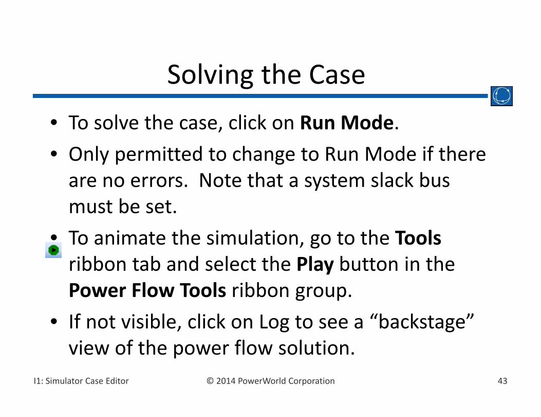
• To solve the case, click on Run Mode.• Only permitted to change to Run Mode if there are no errors. Note that a system slack bus must be set.
• To animate the simulation, go to the Toolsribbon tab and select the Play button in the Power Flow Tools ribbon group.
• If not visible, click on Log to see a “backstage” view of the power flow solution.
Solving the Case

44© 2014 PowerWorld CorporationI1: Simulator Case Editor
• To modify animated line flows, select the Onelines ribbon tab Oneline Display Options. In the Dialog: – click on the Animated Flows Page– check Show Flow Symbols– check Use Fill Color– click on Actual MW Fill Color– select a light green color– select OK
Case Options
45© 2014 PowerWorld CorporationI1: Simulator Case Editor
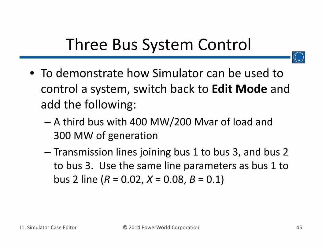
• To demonstrate how Simulator can be used to control a system, switch back to Edit Mode and add the following:– A third bus with 400 MW/200 Mvar of load and 300 MW of generation
– Transmission lines joining bus 1 to bus 3, and bus 2 to bus 3. Use the same line parameters as bus 1 to bus 2 line (R = 0.02, X = 0.08, B = 0.1)
Three Bus System Control
46© 2014 PowerWorld CorporationI1: Simulator Case Editor
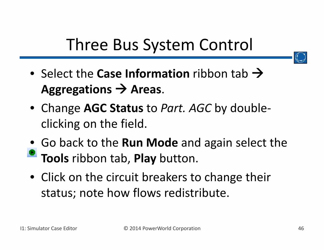
• Select the Case Information ribbon tab Aggregations Areas.
• Change AGC Status to Part. AGC by double‐clicking on the field.
• Go back to the Run Mode and again select the Tools ribbon tab, Play button.
• Click on the circuit breakers to change their status; note how flows redistribute.
Three Bus System Control
47© 2014 PowerWorld CorporationI1: Simulator Case Editor
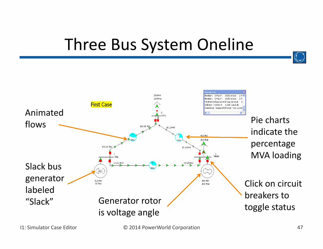
Three Bus System Oneline
Pie chartsindicate thepercentageMVA loading
Animatedflows
Generator rotor is voltage angle
Click on circuitbreakers to toggle status
Slack bus generatorlabeled “Slack”

48© 2014 PowerWorld CorporationI1: Simulator Case Editor
• Pie charts are usually automatically inserted.• For manually inserting, select the Draw ribbon tab, Pies/Gauges Line Flow Pie Chart. Then click on the line midpoint.
• The pie charts are used to graphically indicate the percentage loading of each line.
Inserting Pie Charts
49© 2014 PowerWorld CorporationI1: Simulator Case Editor
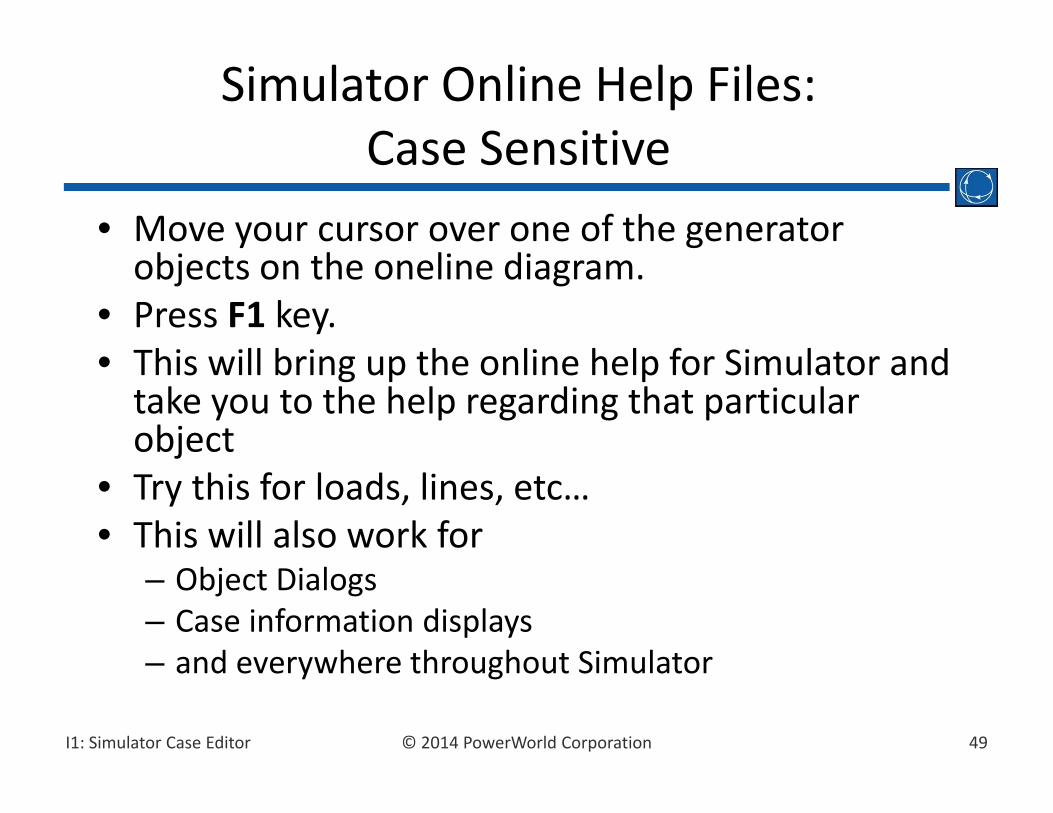
• Move your cursor over one of the generator objects on the oneline diagram.
• Press F1 key.• This will bring up the online help for Simulator and take you to the help regarding that particular object
• Try this for loads, lines, etc…• This will also work for
– Object Dialogs– Case information displays– and everywhere throughout Simulator
Simulator Online Help Files:Case Sensitive

50© 2014 PowerWorld CorporationI1: Simulator Case Editor
• In Edit Mode, select the Options ribbon tabDefault Drawing.
• Changes made here affect only FUTURE onelinedisplay object insertions, not EXISTING objects.
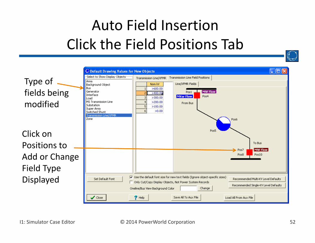
• Click the Field Positions tab choose how fields are automatically inserted around an object.
• Position columns appear in grid. Double‐click a position field to choose the type of field to display, or use the Field Positions diagram to set displayed fields.
Drawing Defaults: Formatting FUTURE Oneline Display Objects
51© 2014 PowerWorld CorporationI1: Simulator Case Editor
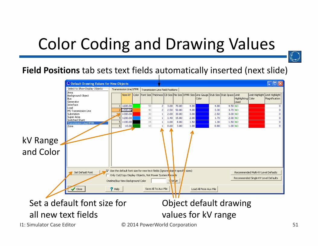
Color Coding and Drawing Values
Object default drawing values for kV range
kV Range and Color
Field Positions tab sets text fields automatically inserted (next slide)
Set a default font size for all new text fields
52© 2014 PowerWorld CorporationI1: Simulator Case Editor
Auto Field InsertionClick the Field Positions Tab
Type of fields being modified
Click on Positions to Add or Change Field Type Displayed
53© 2014 PowerWorld CorporationI1: Simulator Case Editor
• Default Drawing Values only allow you to change the default appearance of FUTURE display objects
• To change the format of EXISTING display objects, make use of the following to features:– Selecting Multiple Objects– Formatting of Selected Objects
Formatting EXISTING Oneline Display Objects

54© 2014 PowerWorld CorporationI1: Simulator Case Editor
• Multiple oneline objects can be selected by different mechanisms:– Individually by left‐clicking on objects while holding down Shift key
– Using the Select buttons to select all objects in a region, available in the Select ribbon group under the Draw ribbon tab.
• Hold Shift‐Ctrl and drag with the left mouse button to select area that encompasses desired objects
• Hold Shift‐Ctrl and drag with the right mouse button to select area that encompasses desired objects and to retain currently selected objects
– Using Select by Criteria, available in the Select ribbon group under the Draw ribbon tab.
Selecting Multiple Objects
55© 2014 PowerWorld CorporationI1: Simulator Case Editor
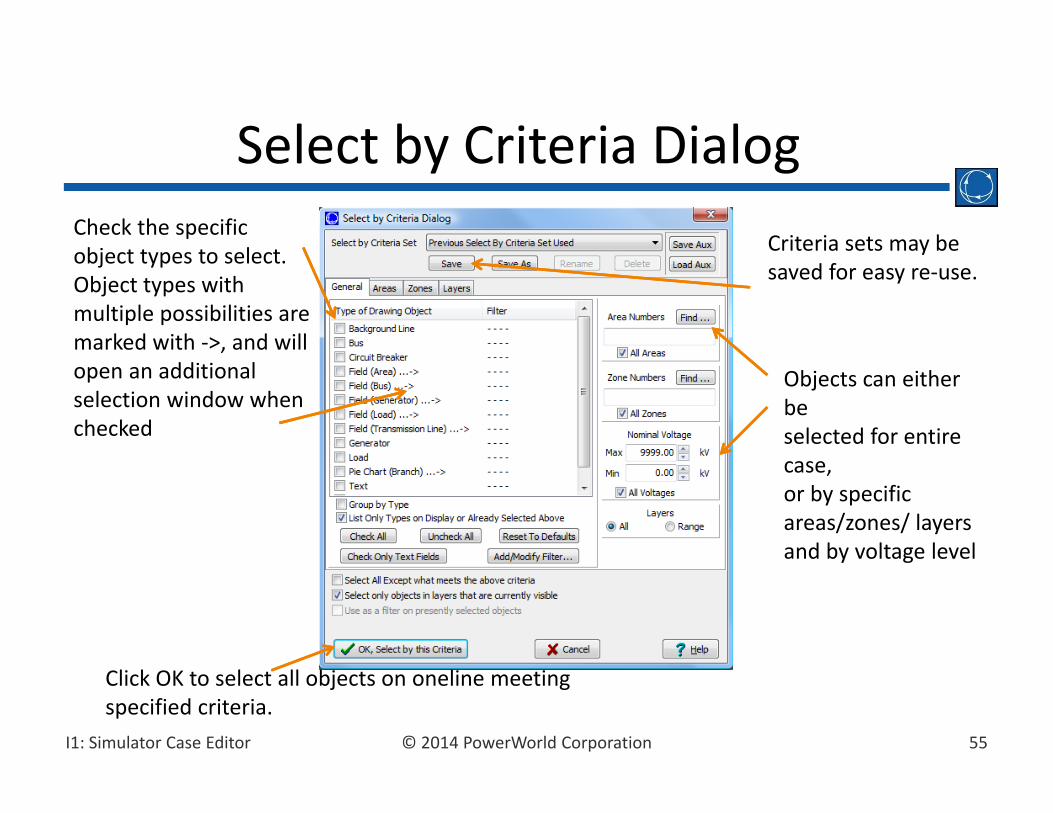
Select by Criteria Dialog
Objects can either beselected for entire case,or by specific areas/zones/ layersand by voltage level
Check the specificobject types to select. Object types with multiple possibilities are marked with ‐>, and will open an additional selection window when checked
Click OK to select all objects on oneline meeting specified criteria.
Criteria sets may be saved for easy re‐use.
56© 2014 PowerWorld CorporationI1: Simulator Case Editor
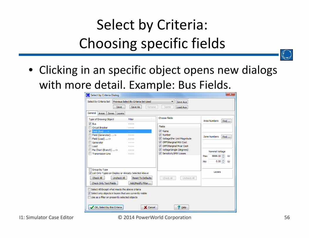
• Clicking in an specific object opens new dialogs with more detail. Example: Bus Fields.
Select by Criteria:Choosing specific fields
57© 2014 PowerWorld CorporationI1: Simulator Case Editor
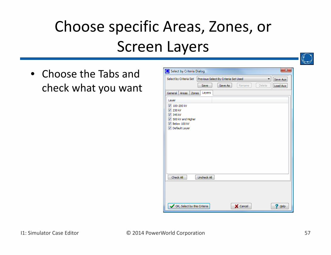
• Choose the Tabs and check what you want
Choose specific Areas, Zones, or Screen Layers

58© 2014 PowerWorld CorporationI1: Simulator Case Editor
• Click on the type of object you’re interested in and click Add/Modify Filter… (or just double‐click on the Filter column)
Use Advanced Filtering in Conjunction with Select By Criteria
Double‐click
Dialog appears
59© 2014 PowerWorld CorporationI1: Simulator Case Editor
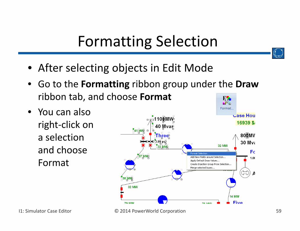
• After selecting objects in Edit Mode• Go to the Formatting ribbon group under the Drawribbon tab, and choose Format
• You can also right‐click on a selection and chooseFormat
Formatting Selection

60© 2014 PowerWorld CorporationI1: Simulator Case Editor
Format Selected Object:Line/Fill
Line Information
Background Color Information
61© 2014 PowerWorld CorporationI1: Simulator Case Editor
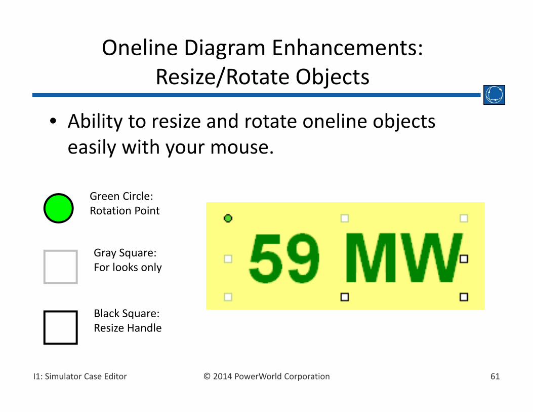
• Ability to resize and rotate oneline objects easily with your mouse.
Oneline Diagram Enhancements:Resize/Rotate Objects
Green Circle:Rotation Point
Black Square:Resize Handle
Gray Square:For looks only

62© 2014 PowerWorld CorporationI1: Simulator Case Editor
• Add oneline objects to layers for customized views. Select the Onelines ribbon tab Layers to create or modify screen layers
• Assign objects to layers using the Levels/Layers button on the Formatting ribbon group on the Draw ribbon tab
Screen Layers
63© 2014 PowerWorld CorporationI1: Simulator Case Editor
• Objects are shown on oneline using four different stack levels, base, background, middle and top.
• By default, different types of objects can have different levels. For example, transmission lines are level middle, while circuit breakers are level top.
• Stack level can be changed by first selecting an object, then using the Levels/Layers button on the Formatting ribbon group under the Draw ribbon tab.
Object Oneline Display Levels
64© 2014 PowerWorld CorporationI1: Simulator Case Editor
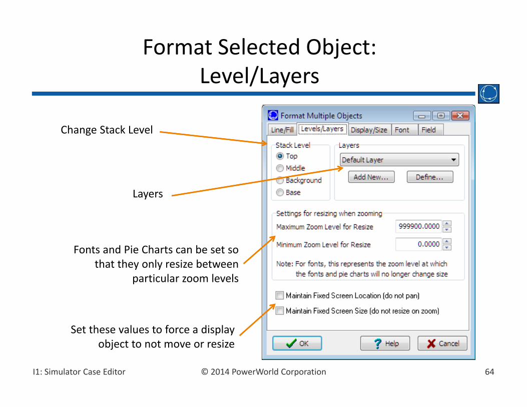
Format Selected Object:Level/Layers
Set these values to force a display object to not move or resize
Change Stack Level
Layers
Fonts and Pie Charts can be set so that they only resize between
particular zoom levels

65© 2014 PowerWorld CorporationI1: Simulator Case Editor
• What is shown on top is first governed by the stack level
• Objects within the same stack level can be moved relative to one another. Go to the Drawribbon tab and choose the Bring to Front or Send to Back buttons from the Formattingribbon group.
Bring To Front / Send To Back
66© 2014 PowerWorld CorporationI1: Simulator Case Editor
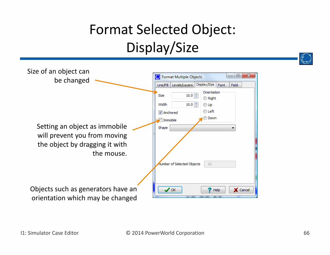
Format Selected Object:Display/Size
Size of an object can be changed
Setting an object as immobile will prevent you from moving the object by dragging it with
the mouse.
Objects such as generators have an orientation which may be changed
67© 2014 PowerWorld CorporationI1: Simulator Case Editor
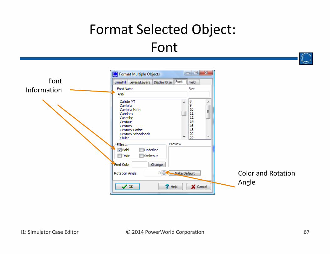
Format Selected Object:Font
Font Information
Color and Rotation Angle
68© 2014 PowerWorld CorporationI1: Simulator Case Editor
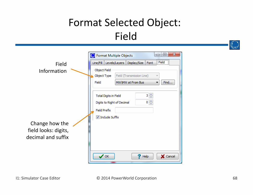
Format Selected Object:Field
Field Information
Change how the field looks: digits, decimal and suffix
69© 2014 PowerWorld CorporationI1: Simulator Case Editor
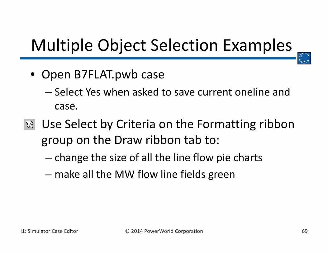
• Open B7FLAT.pwb case– Select Yes when asked to save current oneline and case.
• Use Select by Criteria on the Formatting ribbon group on the Draw ribbon tab to:– change the size of all the line flow pie charts– make all the MW flow line fields green
Multiple Object Selection Examples

70© 2014 PowerWorld CorporationI1: Simulator Case Editor
• Another way to quickly change a large number of objects is to do the following– Select the objects you want to form using Shift‐clicks or Select by Criteria
– Right‐Click on the Selection– Choose Apply Default Draw Values– Dialog at the right comes up
Apply Default Draw Values to Selection

71© 2014 PowerWorld CorporationI1: Simulator Case Editor
• Select a group of oneline objects and then click the button Copy Format– This will copy all the attributes that are the same across the selected objects
• For example: If all objects have a fill color (suppose they are RED), then it will copy this. But if some objects are RED while others are BLUE, it will not copy this attribute.
Applying the format of one object to another: Copy Format
72© 2014 PowerWorld CorporationI1: Simulator Case Editor
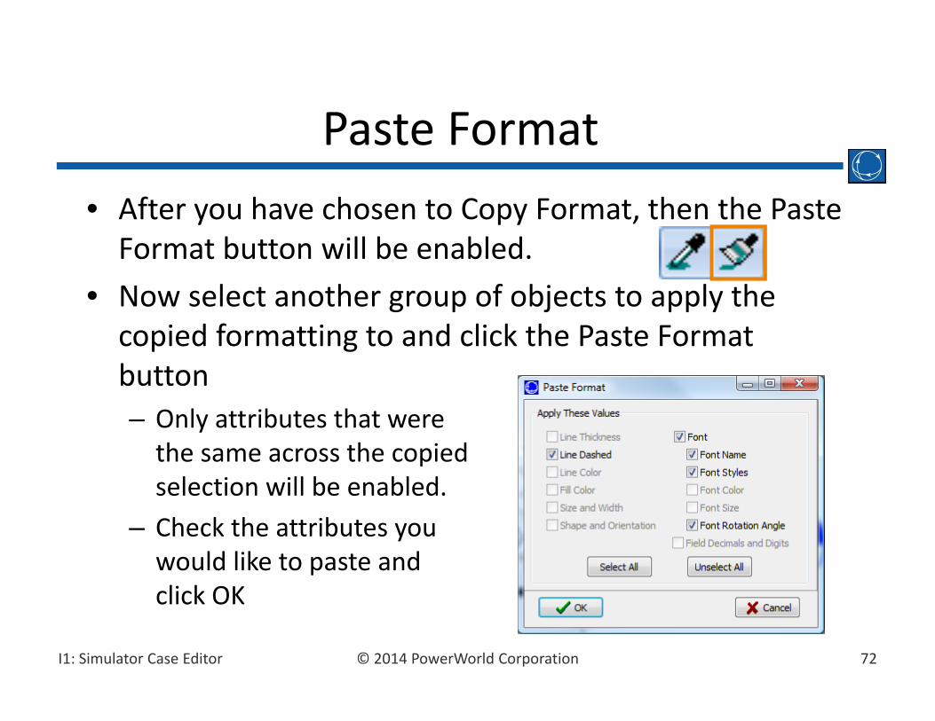
• After you have chosen to Copy Format, then the Paste Format button will be enabled.
• Now select another group of objects to apply the copied formatting to and click the Paste Format button– Only attributes that were the same across the copied selection will be enabled.
– Check the attributes you would like to paste and click OK
Paste Format
73© 2014 PowerWorld CorporationI1: Simulator Case Editor
• Create a link to another oneline by selecting the Draw ribbon tab, Background button Oneline Link– Clicking on this word will open up the other oneline
• Any file can be linked and its associated application will automatically open. – This means that power point files or word documents or spreadsheets can all be linked
Oneline and Document Links

74© 2014 PowerWorld CorporationI1: Simulator Case Editor
• To include pictures, such as bitmaps, JPEGs, or metafiles, on the oneline, select the Draw ribbon tab, Background button Picture.– Use Open Picture Dialog to find desired picture– Dialog provides a preview window
• You can also use the Window’s Clipboard to copy objects from other programs, such as a graph from a spreadsheet or image from web.
Adding Pictures to the Oneline

75© 2014 PowerWorld CorporationI1: Simulator Case Editor
Example: Company Logos

Blank Page