introduction to pumps - atlas.massey.ac.nzatlas.massey.ac.nz/courses/ep/section 2 2010 introduction...
TRANSCRIPT

1
Introduction to Pumps

2
Introduction to Pumps
1.0 INTRODUCTION
There are many different types of pump now available for use in pumped
fluid systems. A knowledge of these pump types and their performance
characteristics is extremely useful in selecting the most suitable pump for
a particular application.
2.0 PUMP CHARACTERISTICS AND THEIR
MEASUREMENT
To understand the performance of a pump it is necessary to be familiar
with the following terms:
FLOW – or Discharge or Delivery litres/minute
DELIVERY HEAD ) metres
SUCTION HEAD ) See diagram below metres
TOTAL HEAD ) metres
EFFICIENCY %
SPEED rpm
DRIVING POWER kilowatts
The Driving Power is the output power delivered by the engine or electric
motor driving the pump. Water Power is the energy given to the water by
the pump; it has no significance except in the calculation of efficiency.
The efficiency of a pump is never 100%. What you get out is always less
than you put in.
%100Power Driving
PowerWater
Input
OutputEfficiency
The Head terms are best illustrated by the following installation, where
water is drawn from a well and delivered to an overhead. tank (Figure 1).

3
Figure 1
Pump Terms
The Suction Head, A, is the vertical height from the water source to the
pump. The Delivery Head, B, is the vertical height from the pump to the
tank, and the Total Static Head is A + B. On the suction side the pump
has to overcome not only static suction head but also the friction head in
the pipe, including the loss at fittings. This extra head is represented by x
and for convenience is shown as the equivalent suction lift. Similarly
there is a friction head, y, for the delivery side. With a very long delivery
pipe this may represent the larger part of the delivery head, but can be
kept at a minimum by increasing the diameter of the delivery pipe.
The total Working Head (A + B + x + y) determines the load against which
the pump works, and thus the general type of pump required and the
power of the driving motor. To test the performance of a pump the
characteristics listed above are measured under closely controlled
conditions in the laboratory. The pump is run over its full operating range
and the data from the tests are presented either in tabular or graphical
form. Using these results, which are generally included in pump
catalogues, a pump can be selected which will meet the requirements of
any job and which will operate at the best efficiency. Examples of
performance graphs for different types of pump are given in the sections
which follow.
4
3.0 TYPES OF PUMP
Of the pumps in use on farms, by far the greatest number belong to one
of three main types, Reciprocating, Rotary and Centrifugal. There are
other types, for example Jet pumps, Airlift pumps and Hydraulic Rams.
• Reciprocating Pumps
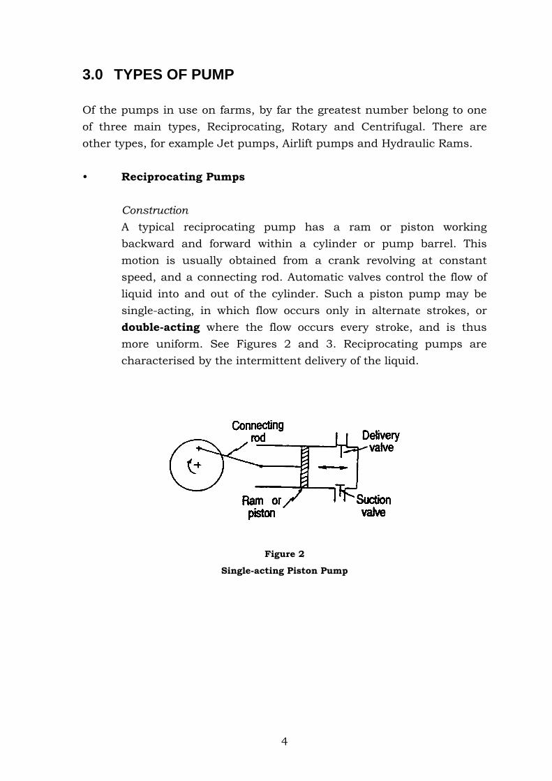
Construction
A typical reciprocating pump has a ram or piston working
backward and forward within a cylinder or pump barrel. This
motion is usually obtained from a crank revolving at constant
speed, and a connecting rod. Automatic valves control the flow of
liquid into and out of the cylinder. Such a piston pump may be
single-acting, in which flow occurs only in alternate strokes, or
double-acting where the flow occurs every stroke, and is thus
more uniform. See Figures 2 and 3. Reciprocating pumps are
characterised by the intermittent delivery of the liquid.
Figure 2
Single-acting Piston Pump

5
Figure 3
Double-acting Piston Pump
A deep-well reciprocating pump operates in the same way as
described above, but the crank is at ground level above the well,
and the cylinder is placed down the well at the lowest expected
water level. A ‘drop pipe’ carries the pumped water from the
cylinder to the surface, and long rods transmit the reciprocating
motion from crank to piston. See Figure 4.
Figure 4 Figure 5
Deep-well reciprocating pump Diaphragm pump
6
The diaphragm pump, commonly used for pumping milk, is also a
positive displacement reciprocating pump. It works in the same
manner as the piston pump, but the piston is replaced with a
flexible rubber diaphragm. This is shown in Figure 5.
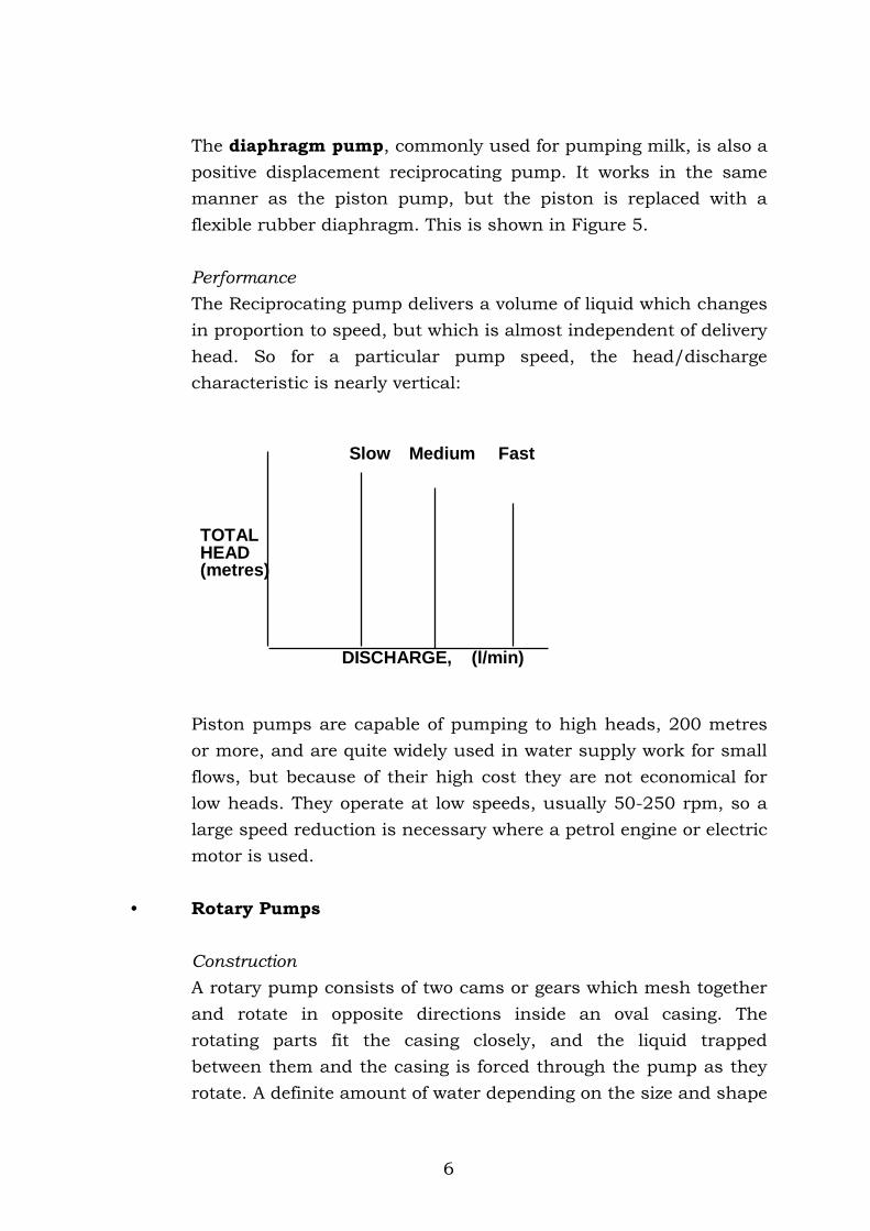
Performance
The Reciprocating pump delivers a volume of liquid which changes
in proportion to speed, but which is almost independent of delivery
head. So for a particular pump speed, the head/discharge
characteristic is nearly vertical:
TOTALHEAD(metres)
Slow Medium Fast
DISCHARGE, (l/min)
Piston pumps are capable of pumping to high heads, 200 metres
or more, and are quite widely used in water supply work for small
flows, but because of their high cost they are not economical for
low heads. They operate at low speeds, usually 50-250 rpm, so a
large speed reduction is necessary where a petrol engine or electric
motor is used.
• Rotary Pumps
Construction
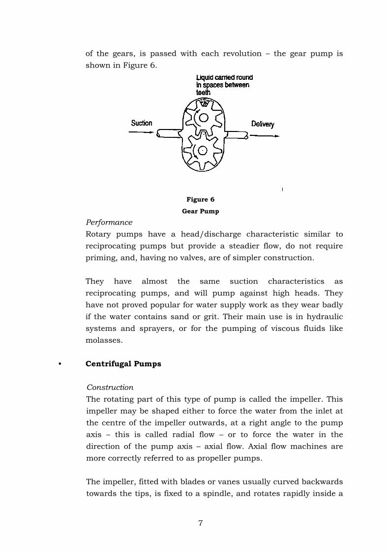
A rotary pump consists of two cams or gears which mesh together
and rotate in opposite directions inside an oval casing. The
rotating parts fit the casing closely, and the liquid trapped
between them and the casing is forced through the pump as they
rotate. A definite amount of water depending on the size and shape
7
of the gears, is passed with each revolution – the gear pump is
shown in Figure 6.
Figure 6
Gear Pump
Performance
Rotary pumps have a head/discharge characteristic similar to
reciprocating pumps but provide a steadier flow, do not require
priming, and, having no valves, are of simpler construction.
They have almost the same suction characteristics as
reciprocating pumps, and will pump against high heads. They
have not proved popular for water supply work as they wear badly
if the water contains sand or grit. Their main use is in hydraulic
systems and sprayers, or for the pumping of viscous fluids like
molasses.
• Centrifugal Pumps
Construction
The rotating part of this type of pump is called the impeller. This
impeller may be shaped either to force the water from the inlet at
the centre of the impeller outwards, at a right angle to the pump
axis – this is called radial flow – or to force the water in the
direction of the pump axis – axial flow. Axial flow machines are
more correctly referred to as propeller pumps.
The impeller, fitted with blades or vanes usually curved backwards
towards the tips, is fixed to a spindle, and rotates rapidly inside a

8
casing. The impeller may be of the closed type where the vanes are
mounted between discs, or of the open type consisting of a hub to
which the vanes are attached. The open impeller does not have
such a high efficiency as the closed type, but is less likely to
become clogged and hence is better adapted to handling liquids
containing solids.
The casing of centrifugal pumps may be of the volute or turbine
type. In the volute the casing gradually increases in cross-section,
causing the velocity head of the water leaving the impeller to be
changed into pressure head as the velocity is reduced towards the
outlet. In the turbine, or diffuser type, a series of fixed blades has
the same effect: this type is not used much in water supply or
irrigation, except in deep well pumps, where the turbine casing
shape lends itself to a cylindrical body. The difference in casing
shape is shown in Figures 7 and 8.
Figure 7 Figure 8
Volute Centrifugal Pump Turbine Centrifugal Pump
Centrifugal pumps give their best performance at a certain rate of
discharge and head, and their efficiency falls off when these
conditions are varied. The head against which a centrifugal pump
with a single impeller – called a Single-Stage Pump – will pump
satisfactorily is usually not very great, less than 50 metres without
undesirably high speeds. For higher heads a Multi-Stage Pump is
used, with two or more impellers arranged in such a way that the
discharge from one impeller enters the centre, or eye, or the next

9
impeller so that delivery head is increased in stages – see Figure 9.
This principle is used in many submersible pumps, where pump
and motor are both placed below the water surface. Delivery to the
surface is through a riser pipe on which the assembly is
suspended.
Figure 9
Multi-stage Centrifugal Pump
Centrifugal pumps need to be primed before starting unless they
are located below the source of water. The suction performance of
centrifugal pumps is not very good, generally less than 5 metres,
and they should be placed as near to the water as possible. Proper
arrangement of the piping is essential if the pump is to operate at
its greatest efficiency. Figure 10 shows a typical centrifugal pump
installation.
Figure 10
Typical Centrifugal Pump Installation
10
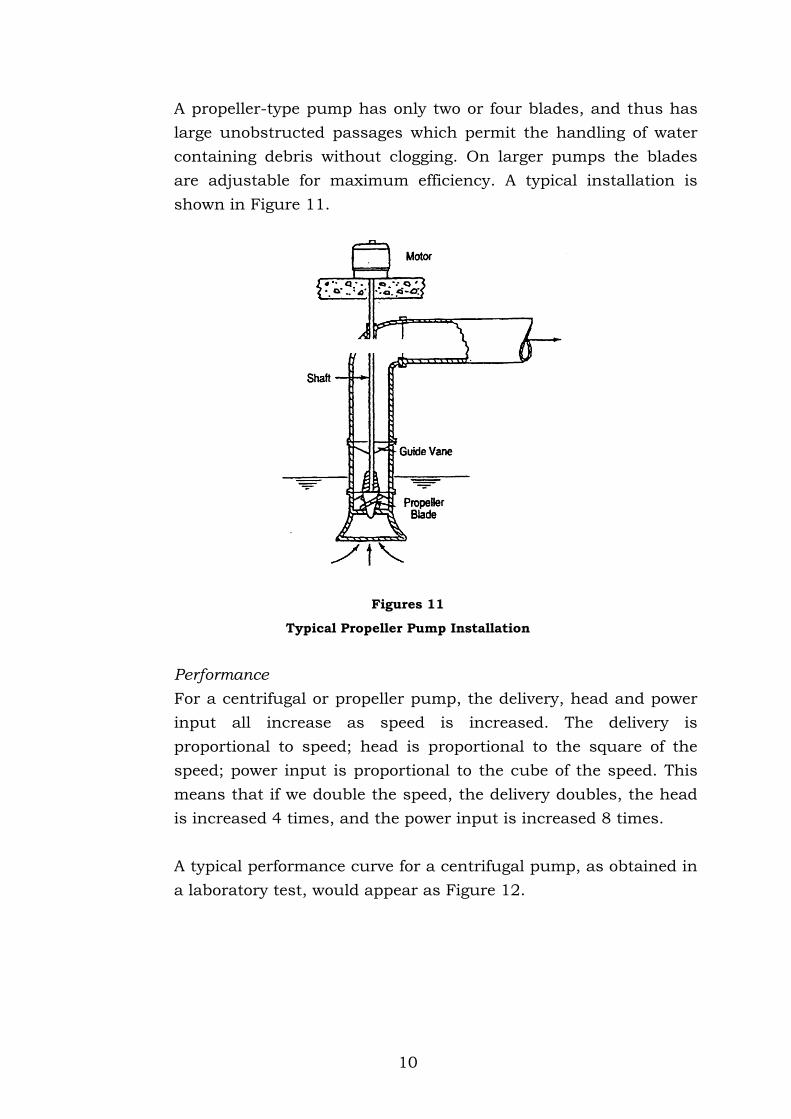
A propeller-type pump has only two or four blades, and thus has
large unobstructed passages which permit the handling of water
containing debris without clogging. On larger pumps the blades
are adjustable for maximum efficiency. A typical installation is
shown in Figure 11.
Figures 11
Typical Propeller Pump Installation
Performance
For a centrifugal or propeller pump, the delivery, head and power
input all increase as speed is increased. The delivery is
proportional to speed; head is proportional to the square of the
speed; power input is proportional to the cube of the speed. This
means that if we double the speed, the delivery doubles, the head
is increased 4 times, and the power input is increased 8 times.
A typical performance curve for a centrifugal pump, as obtained in
a laboratory test, would appear as Figure 12.

11
H e a d(M e t r e s )
P o w e r (k W )
E f f i c i e n c y(% )
P o w e r
E f f i c i e n c y
H e a d
D i s c h a r g e (1 / m i n )
Figure 12
Typical Performance Curve Centrifugal Pump
Repeating the test over the complete speed range of the pump
gives an overall picture of the operational characteristics of the
pump.
Unlike positive displacement pumps, the head developed by a
centrifugal pump varies with the flow or discharge produced by
the pump. In other words the pump can pump a lot of water at a
lower head or a smaller amount of water at a higher head.
The exact flow and head is determined by the interaction of the
pump and pipe system (more about this next year).
It must be noted also that there is a particular flow and head at
which the pump operates most efficiently.

12
3.1 Summary of Pump Characteristics
Advantages Disadvantages
Reciprocating
Pumps
Positive action.
Efficient over a wide range of delivery
and head.
Discharge pulsates.
Subject to vibration.
Sometimes noisy.
Rotary Pumps Positive action.
Occupy little space.
Wide range of speed.
Steady discharge.
Subject to abrasion.
Likely to get noisy.
Centrifugal Pumps Simple design.
Quiet operation.
Steady discharge.
Efficient for pumping large volumes.
Suitable for direct connection to
electric motor.
May be either horizontal or vertical.
Can be multi-staged.
Propeller Pumps Generally as above.
Usually vertical mounting.
Pump very large quantities at low
heads.
Widely used for land drainage and
flood control.
4.0 PUMP CONTROLS
4.1 Pressure Tanks
Historically pressure tanks were the only means of controlling pumps.
With the advent of other control systems, pressure tanks are losing
favour but there are still large numbers in use today.
Pressure tanks operate by pumping water into the tank and compressing
the air trapped at the top of the tank. The pumping operation continues

13
until the air pressure reaches the preset level on the pressure switch and
the pump cuts out.
During the initial stages of water draw-off the air in the tank forces the
water out of the tank into the pipe system. When the air pressure drops
to a preset point the pressure switch starts the pump. The time between
stopping and starting of the pump is known as the cycle time. Most
people assume that the buffer storage capacity of the pressure tank is
equal to the volume of the tank. This, in fact, is incorrect.
The volume of water stored between cut in and cut out is controlled by
Boyle’s Law. This law states that the product of the initial pressure and
volume is equal to the product of the final pressure and volume, i.e.
Pi Vi = Pf Vf
where i = initial
f = final
For example:
Assuming that a 300 litre pressure tank is empty at atmospheric
pressure, and that the cut in pressure is 5 bars absolute (i.e. not gauge
pressure). Therefore:
Pi = 1 bar absolute
Vi = 300 litres of air
Pf = 5 bar absolute
Vf = ?
from Pi Vi = Pf Vf
Vf = P V
P
i i
f
= 1 x 300
5
= 60 litres of air
That is the air which did occupy 300 litres now occupies only 60 litres. So
the volume of water in the tank is = 300 - 60 litres.
14
= 300-60 litres
= 240 litres of water stored
If the cut out pressure is set at 7 bar absolute, then:
Pi = 5 bar absolute
Vi = 60 litres of air
Pf = 7 bar absolute
Vf = ?
from Pi Vi = Pf Vf
Vf = P V
P
i i
f
= 5 bar x 60 litres
7 bar
= 42.8 litres of air
That is the air now occupies 42.8 litres, so the volume of water in the
tank =
= 300-42.8 litres of air
= 257.1 litres
The amount of water stored between cut in and cut out is the difference
between these two numbers, i.e. volume of water stored
= 257.1 – 240.0
= 17.1 litres
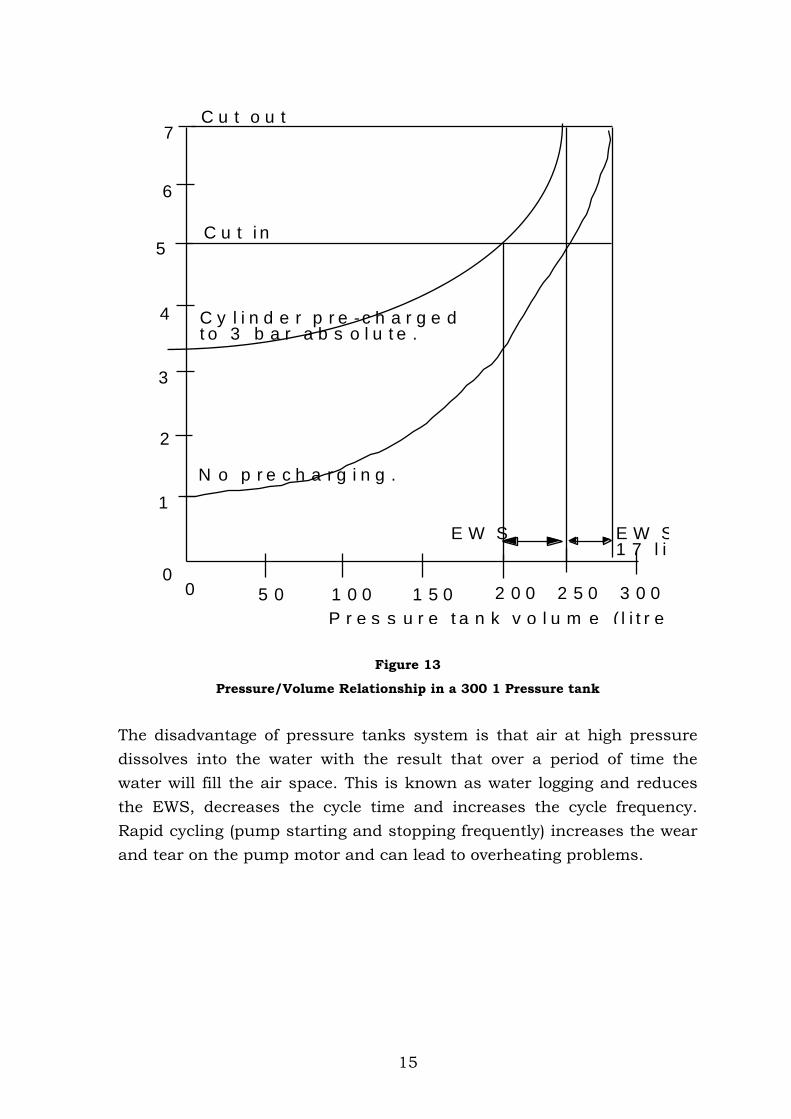
The volume stored is known as the Effective Water Storage (EWS) and in
this case is considerably smaller than the volume of the tank. These
calculations can be represented graphically (Figure 13). Note that
precharging the cylinder with air significantly increases the EWS.
15
P r e s s u r e t a n k v o l u m e ( l i t r e s )
0
1
2
3
4
5
6
7
0 5 0 1 0 0 1 5 0 2 0 0 2 5 0 3 0 0
N o p r e c h a r g i n g .
C u t i n
C u t o u t
C y l i n d e r p r e -c h a r g e dt o 3 b a r a b s o l u t e .
E W S E W S = 1 7 l i t r e s
Figure 13
Pressure/Volume Relationship in a 300 1 Pressure tank
The disadvantage of pressure tanks system is that air at high pressure
dissolves into the water with the result that over a period of time the
water will fill the air space. This is known as water logging and reduces
the EWS, decreases the cycle time and increases the cycle frequency.
Rapid cycling (pump starting and stopping frequently) increases the wear
and tear on the pump motor and can lead to overheating problems.

16
4.2 Aquacells
The low EWS and water logging characteristic of the pressure tank led to
the development of the aquacell (Figure 14). Since the aquacell only
provides a means of operating the pressure switch, its size is kept to a
minimum. The rubber bladder prevents water logging.
The effect of a small EWS (3-5 litres) with large capacity pumps means
that cycling times will be small. The inclusion of a modified check valve
(Figure 15) will help overcome the problem.
Figure 14
Aquacell Pressure Unit
Figure 15
Operation of Modified Check Valve

17
The modified check valves allow full flow when the aquacell is draining
but restricts the flow during filling, therefore increasing filling time and
cycling time.
P r o b e s i g n a la c t i v a t e s s t a r t /s t o ps y s t e m
P r o b e C a b l e 0 -1 0 k m
6 v o l t A / C p o w e r s u p p l y
N e u t r a l
L o w
H i g h
M o t o r
P u m p
3 ¿ p o w e r
Figure 16
Probe Control System
4.3 Probe Control (Figure 16)
In situations where water is being pumped to a storage tank the water
level in the tank can be monitored using probes. The probes are set to
detect maximum level (pump cut out) and minimum level (cut in). The
third probe is a neutral probe. Electrical contact between the probes
relies on the conductivity of the water.
4.4 Flow Sensing Control
The low flow control has a valve which isolates the pressure switch from
the main line at flows greater than 3-5 litres/minute, i.e. at flows above
these, regardless of mainline pressure, the pump will not switch off. The
potential exists for the pump to operate at or near maximum head and
therefore pipelines must be able to withstand these pressures.
Motor
3 phase power

18
Recent developments have produced a flow sensing control unit which
can eliminate the need for storage vessels. The use is made of two
electronic sensors one of which detects the initial drop in pressure within
the line when a demand for water is made. This first sensor starts the
pump which satisfies the flow requirements but raises the pressure. But
as soon as flow starts from the pump a lightly spring loaded valve is
moved to a position where the second sensor can electronically override
the pressure sensor and so flow will continue regardless of the demand,
down to a minimum flow of about 20 litres/hr – these units are only
suitable for centrifugal pumps. A strong advantage of these units over a
pressure switch is that if no water is able to flow for some reason, the
pump will only run for a few seconds before switching off so preventing
pump damage. This protective switching requires manual resetting after
the flow problem is solved.
Figure 17
Flow Sensing Pump Control
4.5 Float Switch Control
Modern float control switches enable tank levels to be controlled by a
simple plastic float with a mercury switch within and attached to a
waterproof electrical cable. This cable is secured to the roof of the tank
with an adjustable clamp which allows level control. When the level of
water is low the float hangs from the cable and the switch causes the
pump to start. As the water level rises the unit floats on the water and
when it eventually comes to a horizontal position the pump is switched
off.

19
Figure 18
Float Switch Pump Control