introduction to scalable multi-port converters
TRANSCRIPT
Introduction to Scalable Multi-Port
Converters Modeling and control of an arbitrary number of power ports
This work has been conducted within the project EPT300, co-funded by grants from Austria,
Germany, The Netherlands, France, Italy, Portugal and the ENIAC Joint Undertaking.
Bas Vermulst
June 14, 2016

Trends in power electronics: multi-port converters
• Traditional power converters
− One input, one output
− Unidirectional power flow
− Stages for ac-dc and dc-dc
• Recent developments
− Multi-port
− Bidirectional power flow
− Combined dc-dc and ac-dc conversion
1

bi-directional multi-port converter
Example application
Household equipment
Photovoltaics Mains grid Stationary battery
Electric vehicle
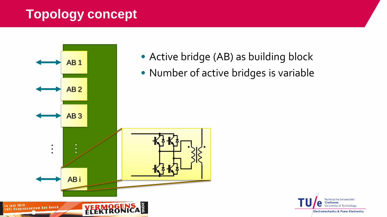
Topology concept
• Active bridge (AB) as building block
• Number of active bridges is variable
…
…
AB 1
AB 2
AB 3
AB i
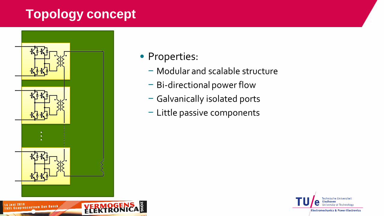
Topology concept
• Properties:
− Modular and scalable structure
− Bi-directional power flow
− Galvanically isolated ports
− Little passive components
…
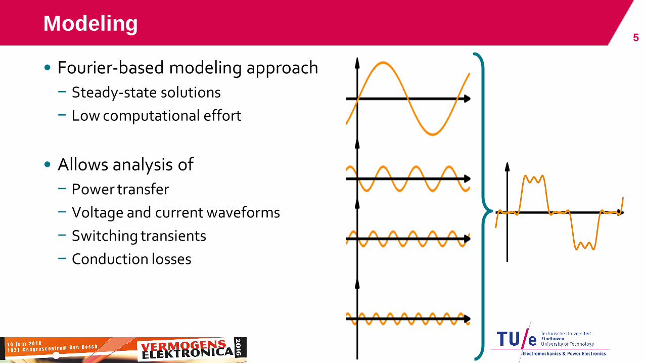
Modeling
• Fourier-based modeling approach
− Steady-state solutions
− Low computational effort
• Allows analysis of
− Power transfer
− Voltage and current waveforms
− Switching transients
− Conduction losses
5
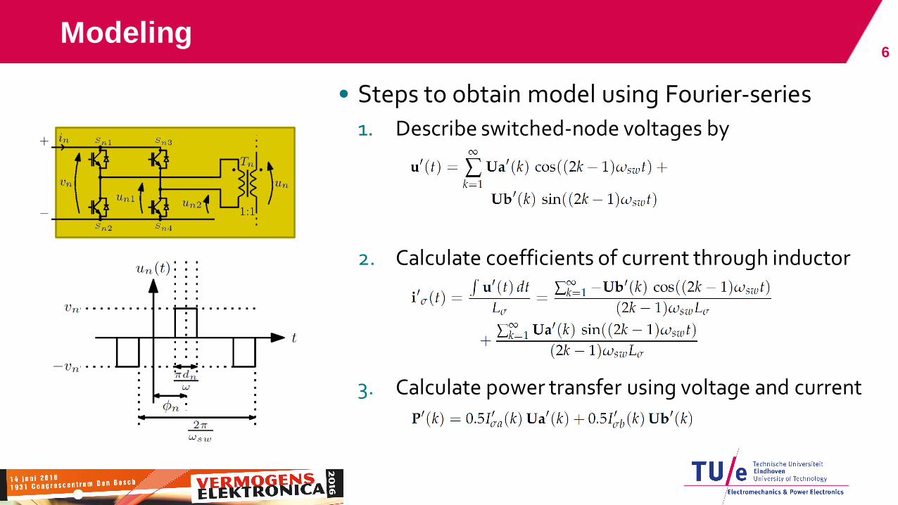
Modeling
• Steps to obtain model using Fourier-series
1. Describe switched-node voltages by
2. Calculate coefficients of current through inductor
3. Calculate power transfer using voltage and current
6

Modeling accuracy 7
(a) Fourier-based model,
truncated at 25 harmonics
(b) Plexim PLECS simulation
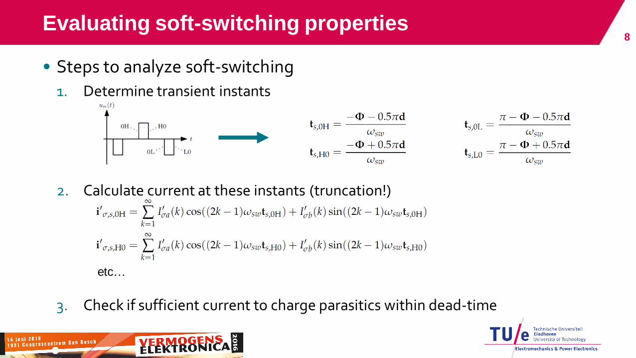
Evaluating soft-switching properties
• Steps to analyze soft-switching
1. Determine transient instants
2. Calculate current at these instants (truncation!)
3. Check if sufficient current to charge parasitics within dead-time
8
etc…
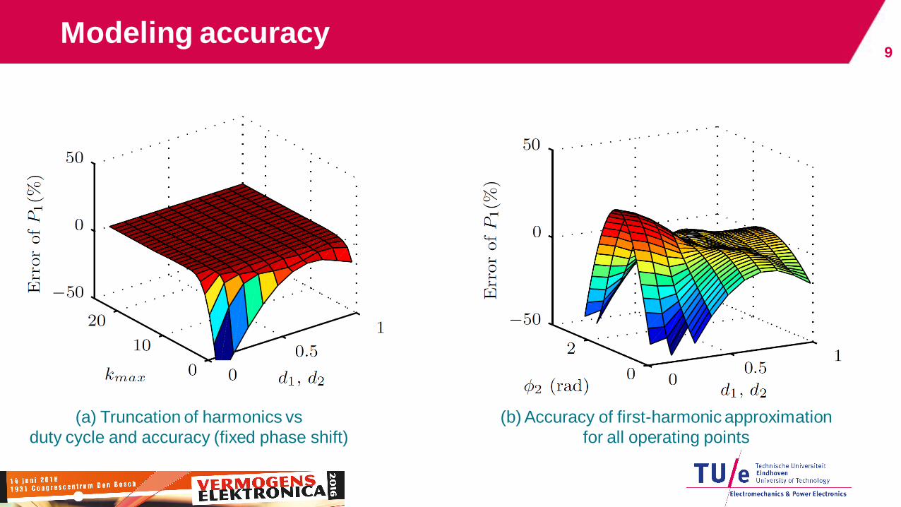
Modeling accuracy 9
(a) Truncation of harmonics vs
duty cycle and accuracy (fixed phase shift)
(b) Accuracy of first-harmonic approximation
for all operating points
Model truncation
•
10
Modulation scheme
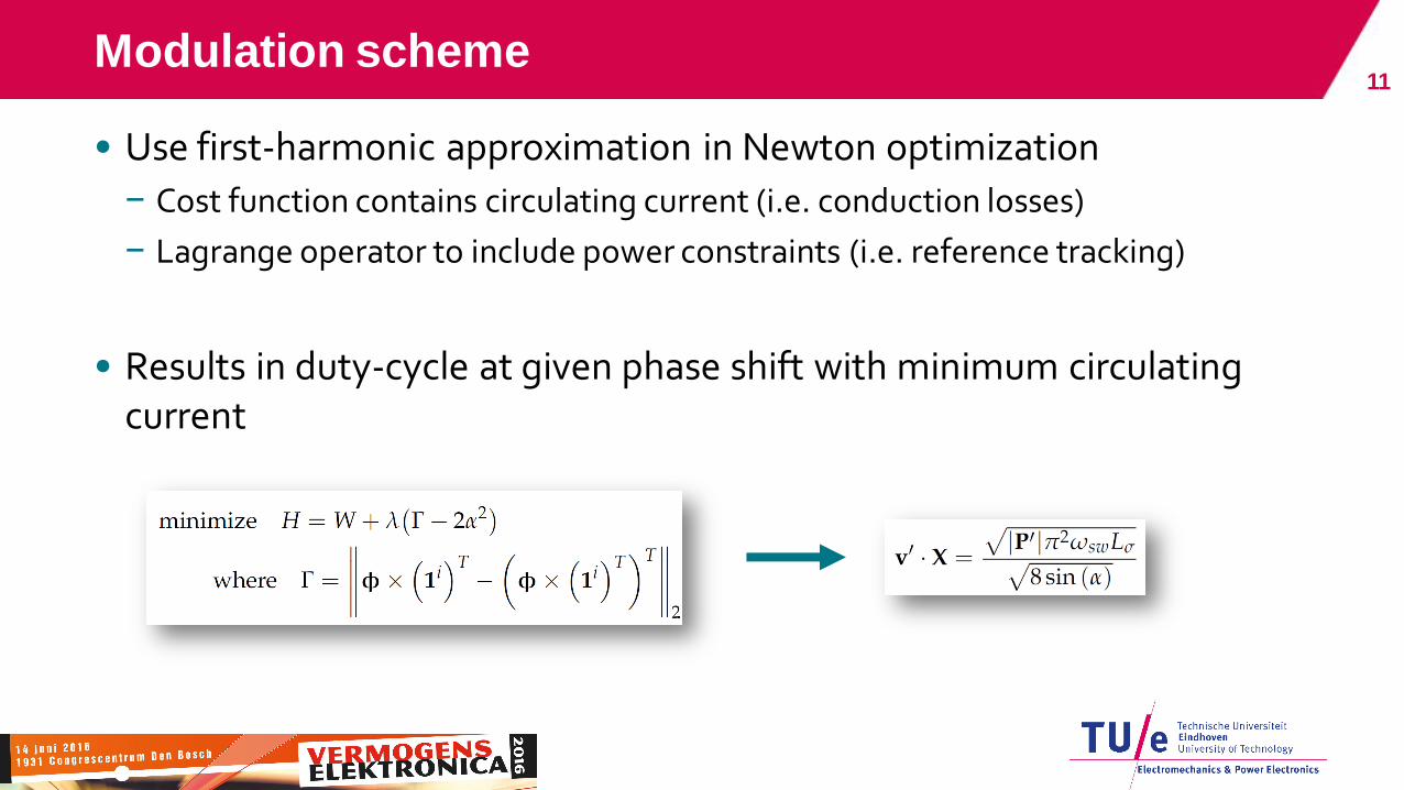
• Use first-harmonic approximation in Newton optimization
− Cost function contains circulating current (i.e. conduction losses)
− Lagrange operator to include power constraints (i.e. reference tracking)
• Results in duty-cycle at given phase shift with minimum circulating current
11

• Multiple strategies possible
• E.g. phase-shift that results in:
− Minimum conduction losses, or
− Lowest thermal stress, or
− Combination of both
12 Modulation scheme
Varying circulating current with fixed port output power
First-harmonic phasor diagram
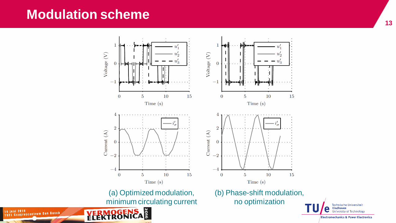
Modulation scheme 13
(a) Optimized modulation,
minimum circulating current
(b) Phase-shift modulation,
no optimization
dc
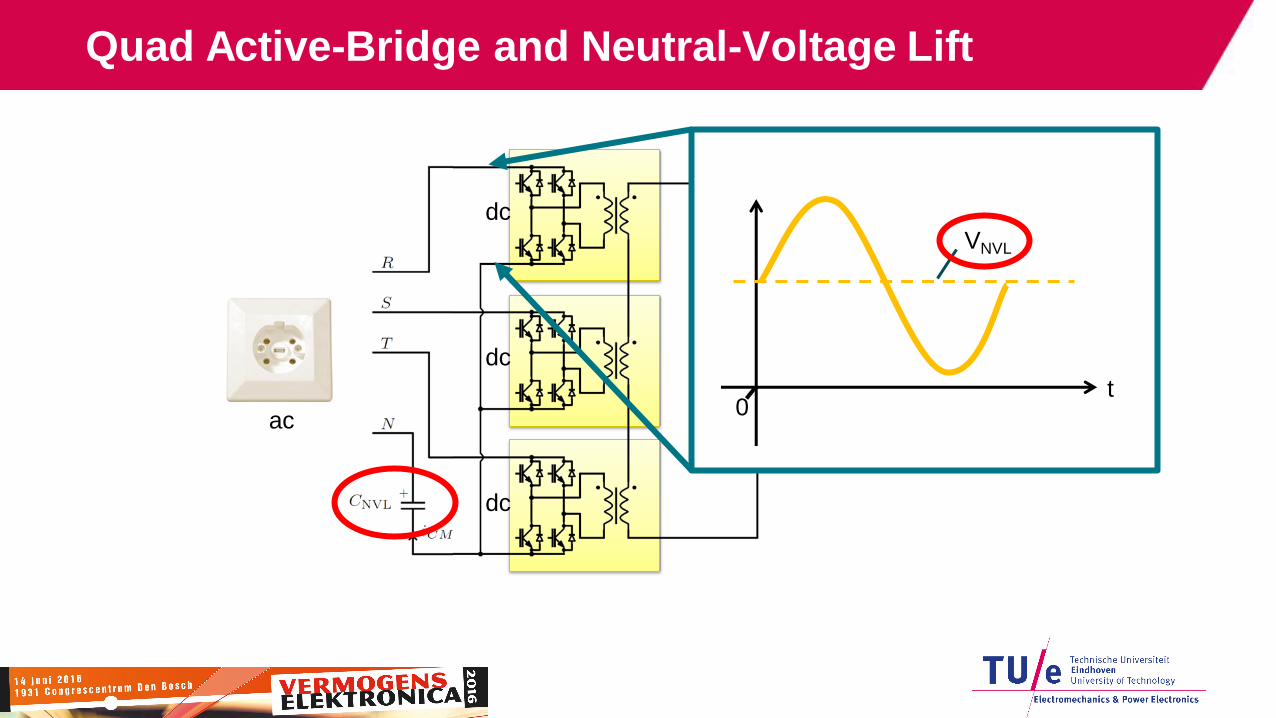
Quad Active-Bridge and Neutral-Voltage Lift
VNVL
t 0
ac
dc
dc
dc

Prototype
Parameter Value
Maximum output power 20 kW
Power ports 4 (“QAB”)
Neutral-voltage lift
Semiconductor material SiC
Switching frequency 45 kHz
Cooling Forced air
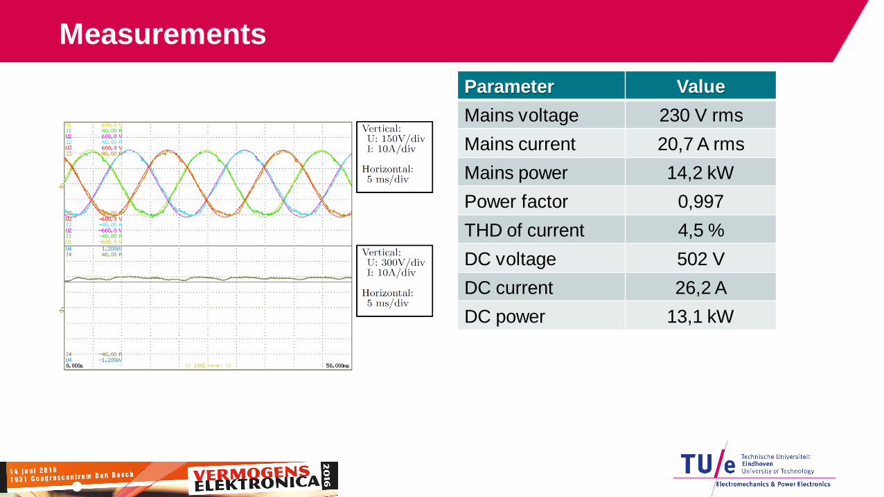
Measurements
Parameter Value
Mains voltage 230 V rms
Mains current 20,7 A rms
Mains power 14,2 kW
Power factor 0,997
THD of current 4,5 %
DC voltage 502 V
DC current 26,2 A
DC power 13,1 kW

Measurements
Parameter Value
Mains power 5 kW -5 kW

Measurements 18
• Converter start-up behavior
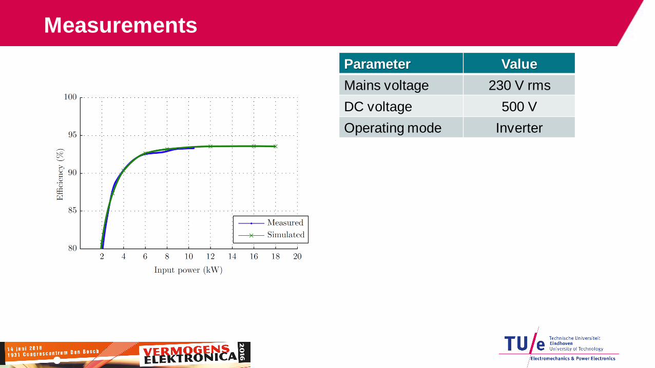
Measurements
Parameter Value
Mains voltage 230 V rms
DC voltage 500 V
Operating mode Inverter
Conclusion
• Framework for multi-port converters
− Topology concept
− Modeling
− Modulation scheme
− Neutral-voltage lift for ac-connections
• Experimental verification on 20 kW prototype in ac-dc application
• Multi-port converters are a competitive solution in a wide range of applications
20