introduction to solar thermal systems
DESCRIPTION
Presentation of Solar technician training program conducted by Everon at Madurai Kamaraj UniversityTRANSCRIPT
SOLAR THERMAL SYSTEMS
SOLAR THERMAL SYSTEMS
Fazil Hassan P
RURAL ENERGY CENTRE
GANDHIGRAM RURAL INSTITUTE-DEEMED UNIVERSITY
DINDIGUL
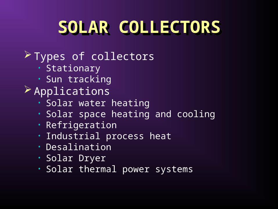
SOLAR COLLECTORSSOLAR COLLECTORS
Types of collectors• Stationary• Sun tracking
Applications• Solar water heating• Solar space heating and cooling• Refrigeration• Industrial process heat• Desalination• Solar Dryer• Solar thermal power systems

Types of solar collectorsTypes of solar collectors
Motion Collector typeAbsorber
typeConcentration
ratio
Indicative temperature range (°C)
Stationary
Flat plate collector (FPC) Flat 1 30-80
Evacuated tube collector (ETC) Flat 1 50-200
Compound parabolic collector (CPC) Tubular1-5 60-240
Single-axis tracking
5-15 60-300
Linear Fresnel reflector (LFR) Tubular 10-40 60-250
Parabolic trough collector (PTC) Tubular 15-45 60-300
Cylindrical trough collector (CTC) Tubular 10-50 60-300
Two-axes tracking
Parabolic dish reflector (PDR) Point 100-1000 100-500
Heliostat field collector (HFC) Point 100-1500 150-2000
Note: Concentration ratio is defined as the aperture area divided by the receiver/absorber area of the collector.

Modes of TrackingModes of Tracking

Comparison of energy absorbed for various modes of tracking
Comparison of energy absorbed for various modes of tracking
Tracking modeSolar energy (kWh/m2) Percent to full tracking
E SS WS E SS WS
Full tracking 8.43 10.60 5.70 100.0 100.0 100.0
E-W Polar 8.43 9.73 5.23 100.0 91.7 91.7
N-S Horizontal 6.22 7.85 4.91 73.8 74.0 86.2
E-W Horizontal 7.51 10.36 4.47 89.1 97.7 60.9
Note: E - Equinoxes, SS - Summer Solstice, WS - Winter Solstice

Stationary collectorsStationary collectors
No concentration

Flat-plate collectorFlat-plate collector
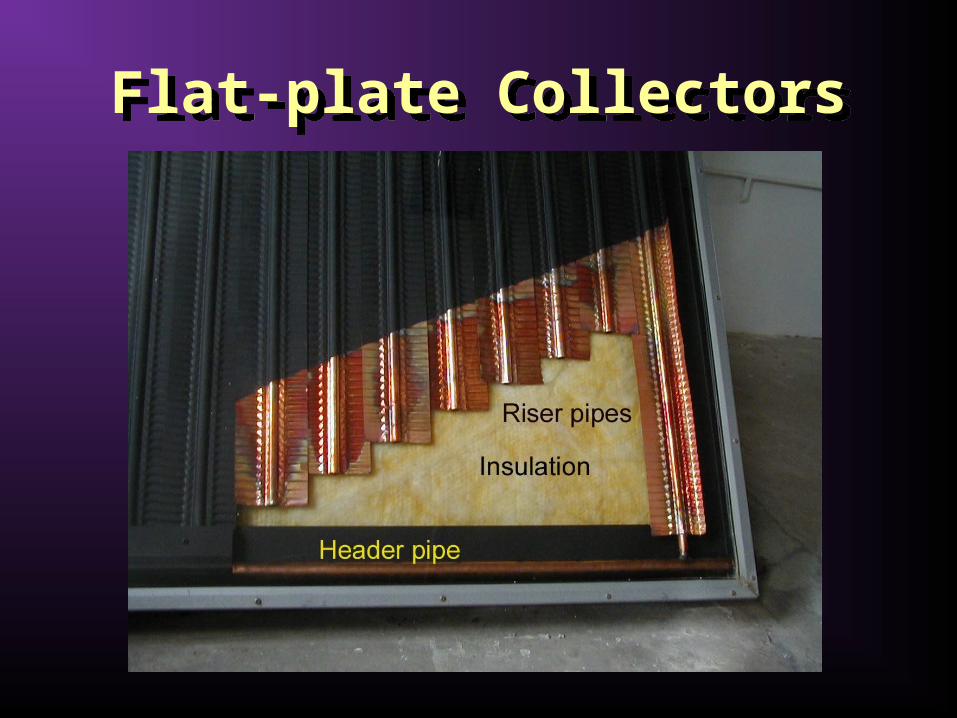
Flat-plate CollectorsFlat-plate Collectors

Types of flat-plate collectorsWater systems
Types of flat-plate collectorsWater systems
GlazingRiserAbsorbing plate
Insulation
A
BGlazingRiserAbsorbing plate
Insulation
CGlazingRiserAbsorbing plate
Insulation
DGlazingRiserAbsorbing plate
Insulation

Types of flat-plate collectorsAir systems
Types of flat-plate collectorsAir systems
GlazingAir passage
Insulation
E
FGlazingAir flowMetal matrix
Insulation
G
GlazingCorrugated sheet
Insulation

Schematic diagram of an evacuated tube collectorSchematic diagram of an evacuated tube collector
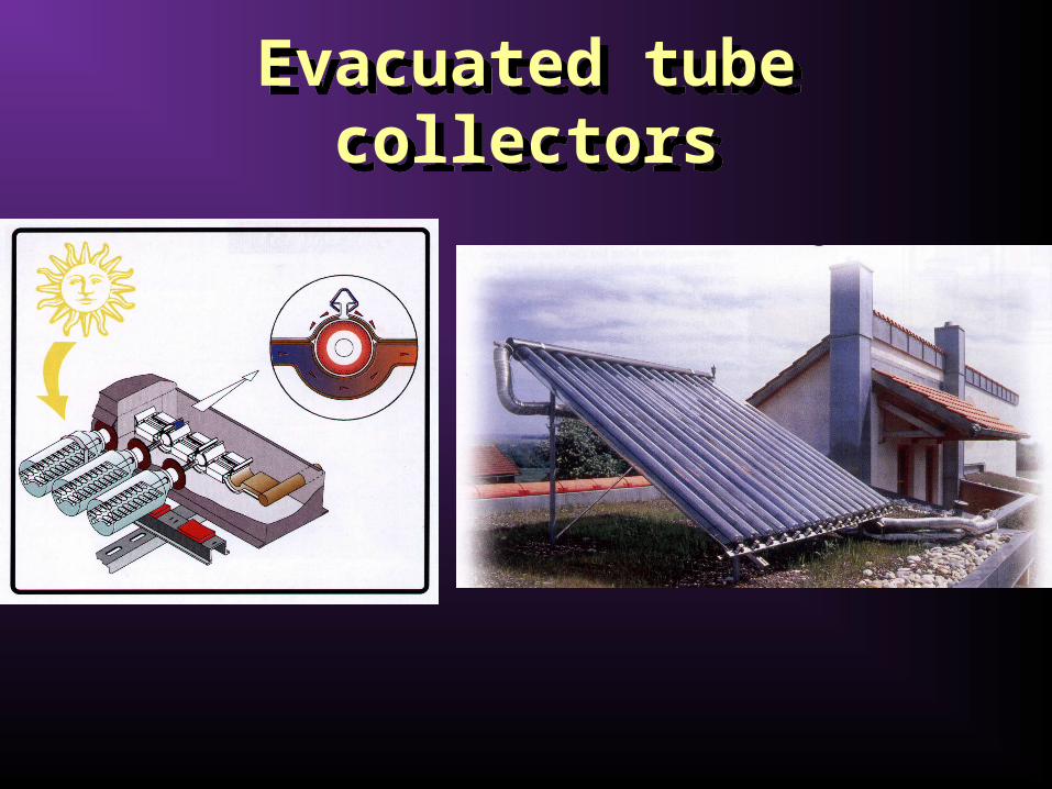
Evacuated tube collectorsEvacuated tube collectors

Stationary collectorsStationary collectors
Concentrating
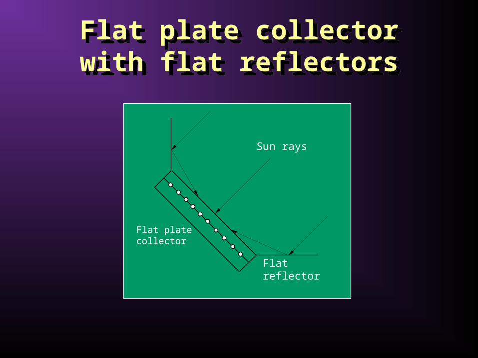
Flat plate collector with flat reflectors
Flat plate collector with flat reflectors
Sun rays
Flat reflector
Flat plate collector
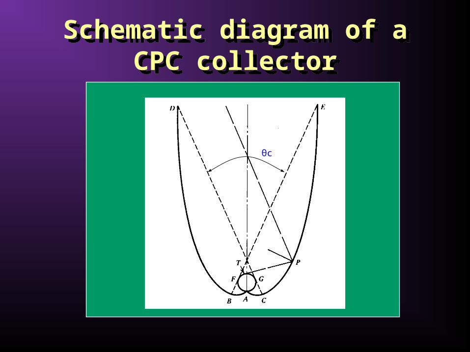
Schematic diagram of a CPC collector
Schematic diagram of a CPC collector
θc

Sun tracking collectorsSun tracking collectors
Concentrating
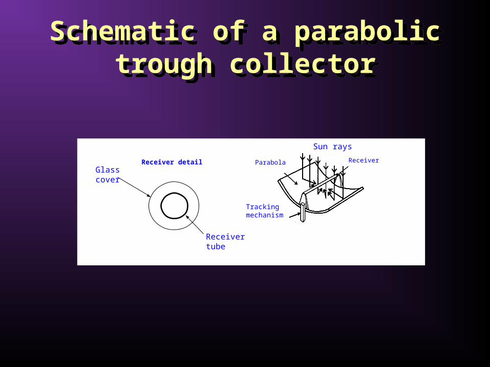
Schematic of a parabolic trough collector
Schematic of a parabolic trough collector
Receiver tube
Glass cover
Receiver detail Receiver
Sun rays
Tracking mechanism
Parabola

Parabolic trough collectorsParabolic trough collectors

Fresnel type parabolic trough collector
Fresnel type parabolic trough collector
Sun rays

Linear Fresnel Reflector (LFR)Linear Fresnel Reflector (LFR)
Sun rays
Receiver
Tower
Mirrors
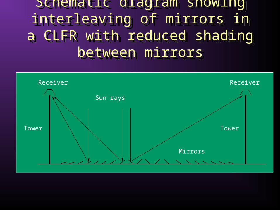
Schematic diagram showing interleaving of mirrors in a CLFR with
reduced shading between mirrors
Schematic diagram showing interleaving of mirrors in a CLFR with
reduced shading between mirrors
Receiver Receiver
Tower Tower
Sun rays
Mirrors

Schematic of a parabolic dish collector
Schematic of a parabolic dish collector
Parabola
Sun rays
Receiver
Two-axes tracking mechanism
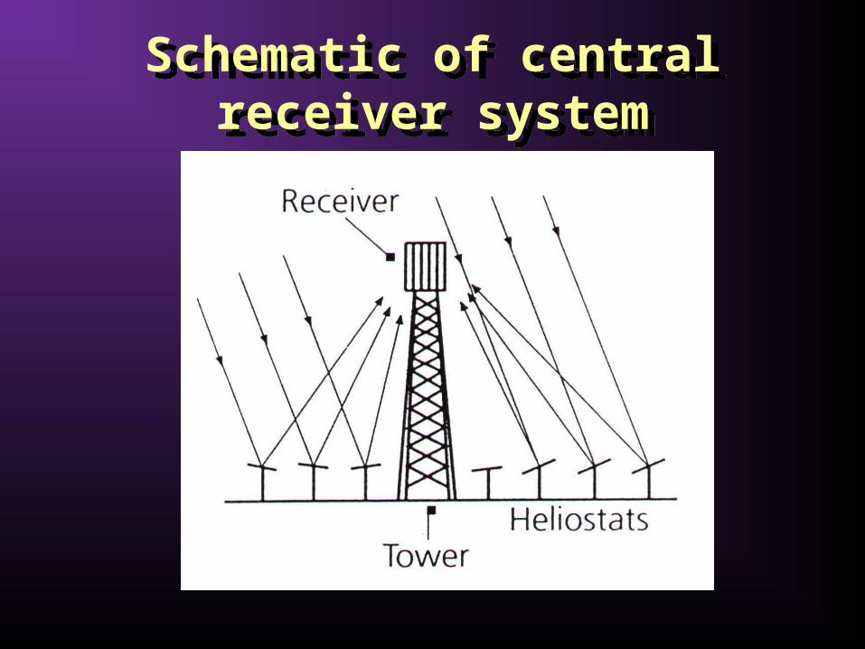
Schematic of central receiver system
Schematic of central receiver system

SOLAR COLLECTOR APPLICATIONS
SOLAR COLLECTOR APPLICATIONS
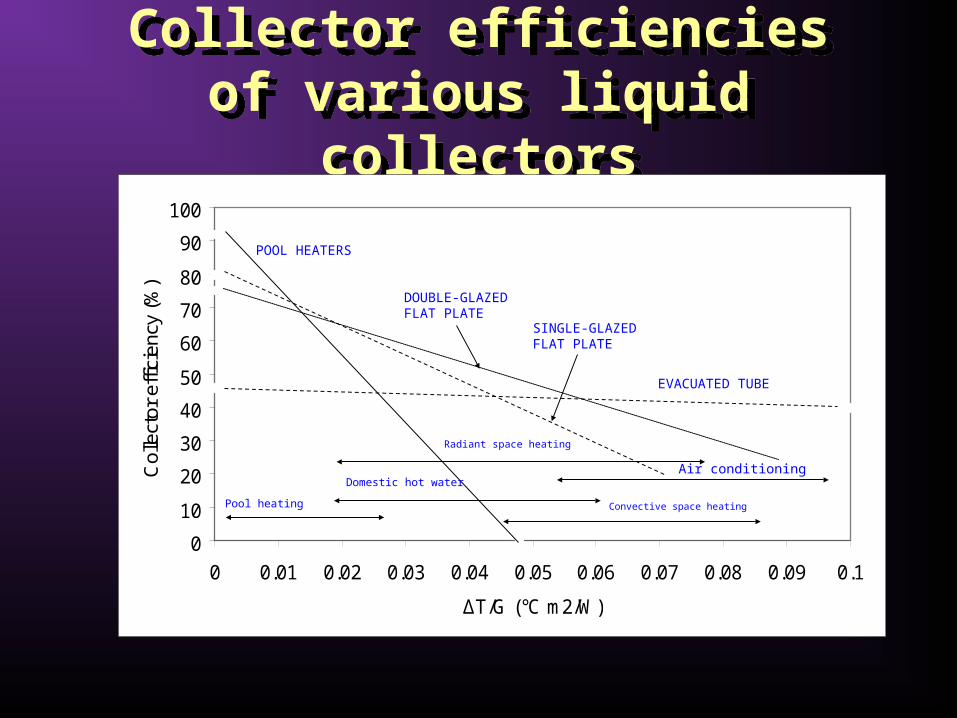
Collector efficiencies of various liquid collectorsCollector efficiencies of various liquid collectors
0
10
20
30
40
50
60
70
80
90
100
0 0.01 0.02 0.03 0.04 0.05 0.06 0.07 0.08 0.09 0.1
ΔT/G (°C m2/W)
Col
lect
or e
ffici
ency
(%
)
Pool heating
Air conditioning
POOL HEATERS
EVACUATED TUBE
DOUBLE-GLAZED FLAT PLATE
SINGLE-GLAZED FLAT PLATE
Domestic hot water
Radiant space heating
Convective space heating

Solar energy applications and type of collectors used
Solar energy applications and type of collectors used
Application System Collector
Solar water heatingThermosyphon systemsIntegrated collector storageDirect circulationIndirect water heating systemsAir systems
PassivePassiveActiveActiveActive
FPCCPC
FPC, CPC ETCFPC, CPC ETC
FPC
Space heating and coolingSpace heating and service hot waterAir systemsWater systemsHeat pump systemsAbsorption systemsAdsorption (desiccant) coolingMechanical systems
ActiveActiveActiveActiveActiveActiveActive
FPC, CPC ETCFPC
FPC, CPC ETCFPC, CPC ETCFPC, CPC ETCFPC, CPC ETC
PDR
Solar refrigerationAdsorption unitsAbsorption units
ActiveActive
FPC, CPC ETCFPC, CPC ETC

Solar energy applications and type of collectors used
Solar energy applications and type of collectors used
Application System Collector
Industrial process heatIndustrial air and water systemsSteam generation systems
ActiveActive
FPC, CPC ETCPTC, LFR
Solar desalinationSolar stillsMulti-stage flash (MSF)Multiple effect boiling (MEB)Vapour compression (VC)
PassiveActiveActiveActive
-FPC, CPC ETCFPC, CPC ETCFPC, CPC ETC
Solar thermal power systemsParabolic trough collector systemsParabolic tower systemsParabolic dish systemsSolar furnacesSolar chemistry systems
ActiveActiveActiveActiveActive
PTCHFCPDR
HFC, PDRCPC, PTC, LFR

Solar Water Heating SystemsSolar Water Heating SystemsThermosyphon systems
Integrated collector storage systemsDirect circulation systems
Indirect water heating systems Air systems

Thermosyphon systems (passive)
Thermosyphon systems (passive)
Thermosyphon systems heat potable water or heat transfer fluid and use natural convection to transport it from the collector to storage.
The water in the collector expands becoming less dense as the sun heats it and rises through the collector into the top of the storage tank.
There it is replaced by the cooler water that has sunk to the bottom of the tank, from which it flows down the collector.
The circulation continuous as long as there is sunshine. Since the driving force is only a small density difference larger
than normal pipe sizes must be used to minimise pipe friction. Connecting lines must be well insulated to prevent heat losses
and sloped to prevent formation of air pockets which would stop circulation.

Schematic diagram of a thermosyphon solar water heater
Schematic diagram of a thermosyphon solar water heater
Auxiliary
Storage tank Hot water outlet
Cold water inlet

Typical thermosyphon solar water heater
Typical thermosyphon solar water heater

Laboratory modelLaboratory model
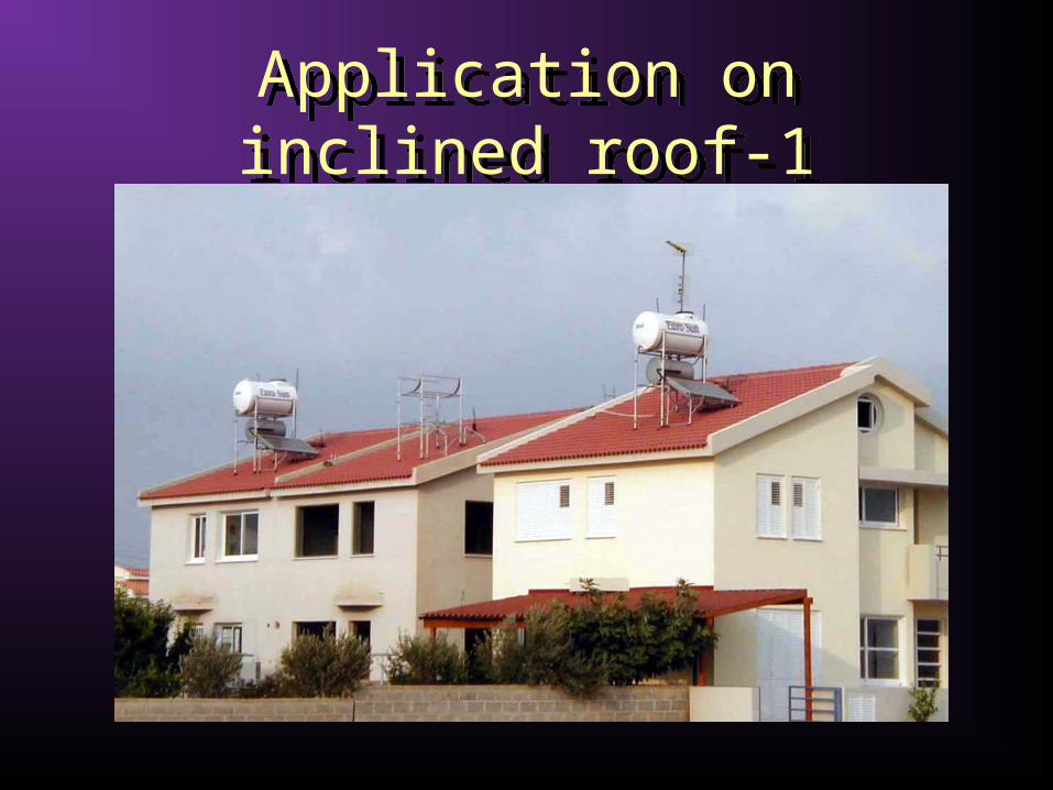
Application on inclined roof-1Application on inclined roof-1
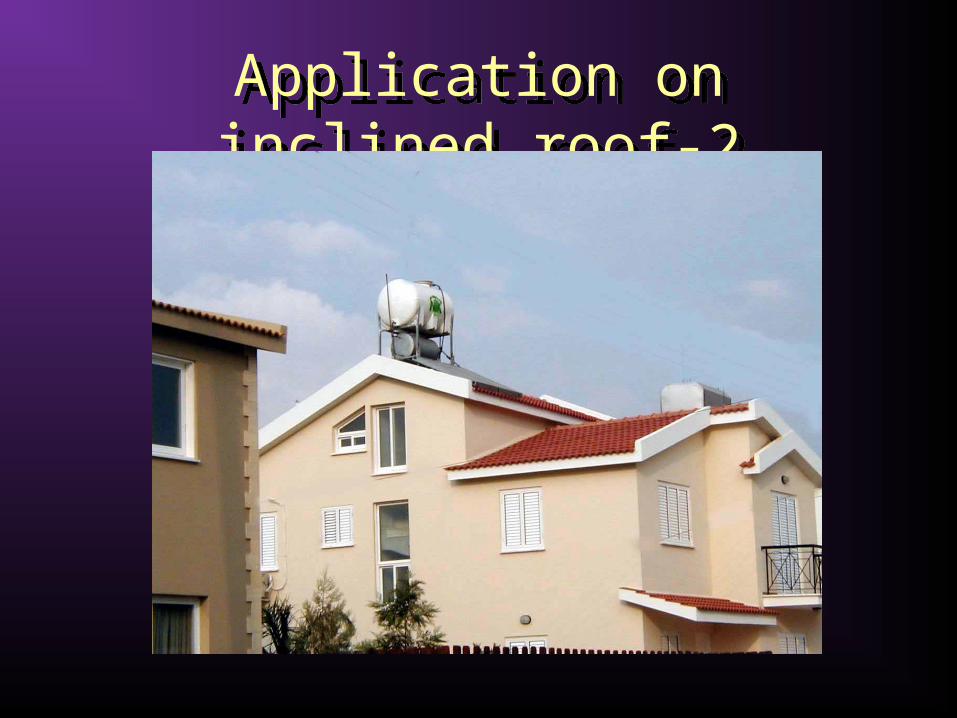
Application on inclined roof-2Application on inclined roof-2
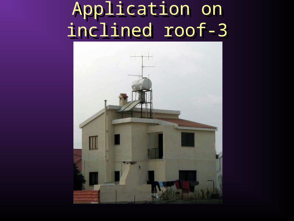
Application on inclined roof-3Application on inclined roof-3

Multi-residential applicationMulti-residential application
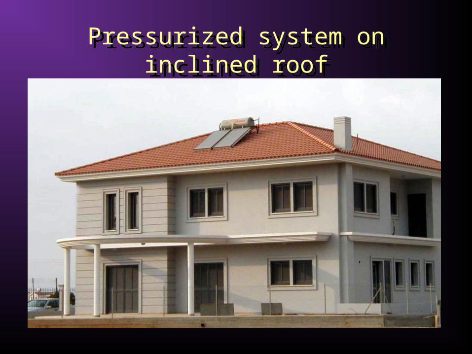
Pressurized system on inclined roofPressurized system on inclined roof
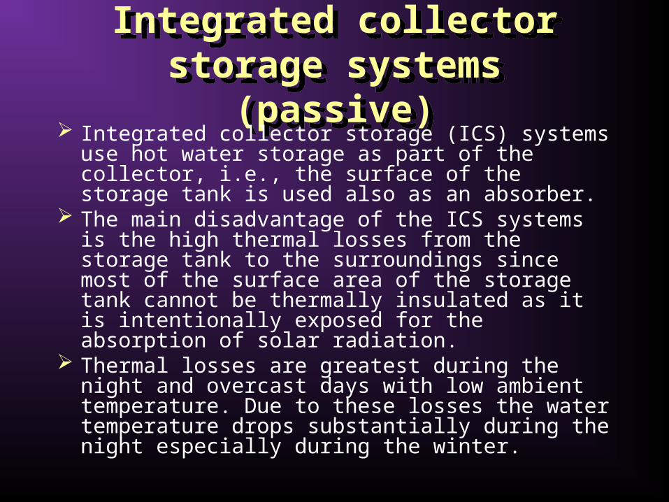
Integrated collector storage systems (passive)
Integrated collector storage systems (passive)
Integrated collector storage (ICS) systems use hot water storage as part of the collector, i.e., the surface of the storage tank is used also as an absorber.
The main disadvantage of the ICS systems is the high thermal losses from the storage tank to the surroundings since most of the surface area of the storage tank cannot be thermally insulated as it is intentionally exposed for the absorption of solar radiation.
Thermal losses are greatest during the night and overcast days with low ambient temperature. Due to these losses the water temperature drops substantially during the night especially during the winter.
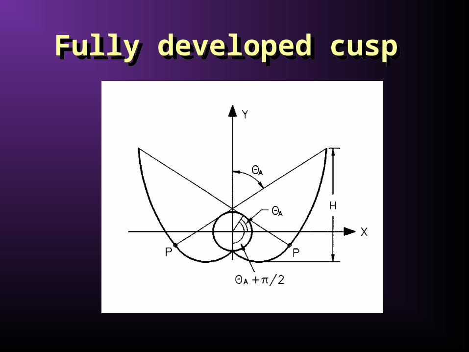
Fully developed cusp Fully developed cusp
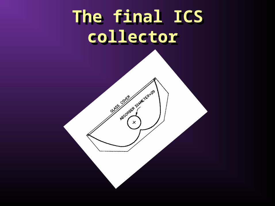
The final ICS collector The final ICS collector

Direct circulation systems (active)
Direct circulation systems (active)
In direct circulation systems a pump is used to circulate potable water from storage to the collectors when there is enough available solar energy to increase its temperature and then return the heated water to the storage tank until it is needed.
As a pump circulates the water, the collectors can be mounted either above or below the storage tank.
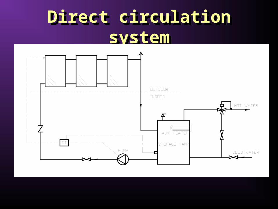
Direct circulation systemDirect circulation system

Drain-down systemDrain-down system
When a freezing condition or a power failure occurs, the system drains automatically by isolating the collector array and exterior piping from the make-up water supply and draining it using the two normally open (NO) valves

Direct or forced circulation type domestic SWH
Direct or forced circulation type domestic SWH
In this system only the solar panels are visible on the roof.
The hot water storage tank is located indoors in a plantroom. • The system is completed with piping, pump and a
differential thermostat.
This type of system is more appealing mainly due to architectural and aesthetic reasons but also more expensive.
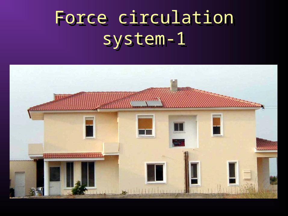
Force circulation system-1Force circulation system-1

Force circulation system-2Force circulation system-2
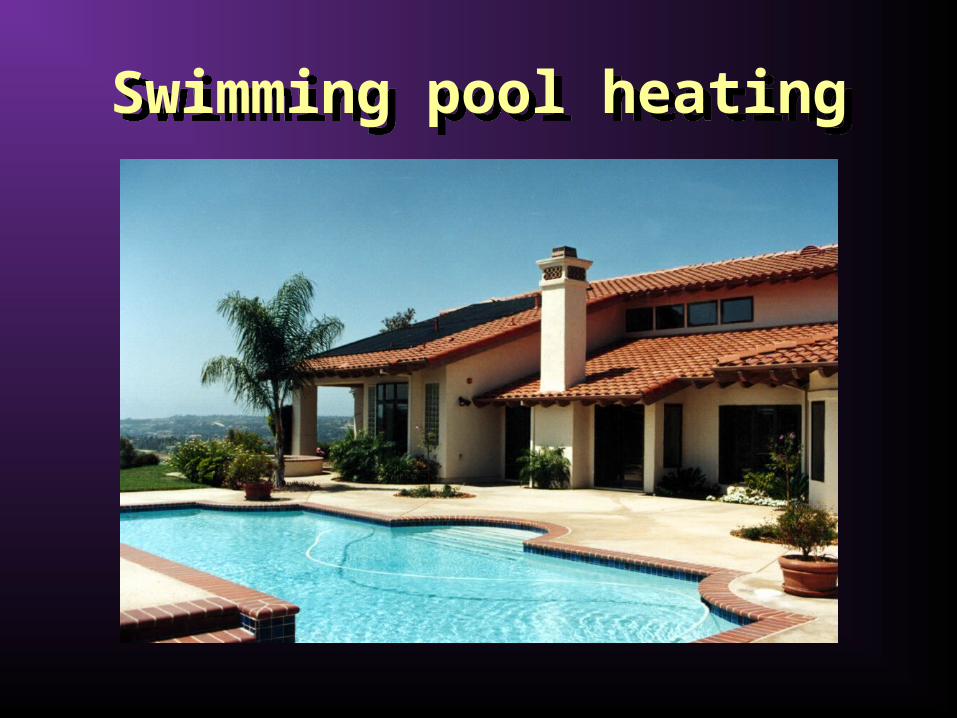
Swimming pool heatingSwimming pool heating
Indirect water heating systems (active)
Indirect water heating systems (active)
Indirect water heating systems circulate a heat transfer fluid through the closed collector loop to a heat exchanger, where its heat is transferred to the potable water.
The most commonly used heat transfer fluids are water/ethylene glycol solutions, although other heat transfer fluids such as silicone oils and refrigerants can also be used.
The heat exchanger can be located inside the storage tank, around the storage tank (tank mantle) or can be external.
It should be noted that the collector loop is closed and therefore an expansion tank and a pressure relief valve are required.
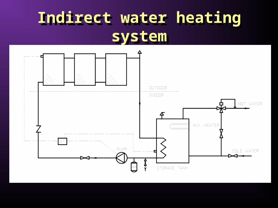
Indirect water heating systemIndirect water heating system
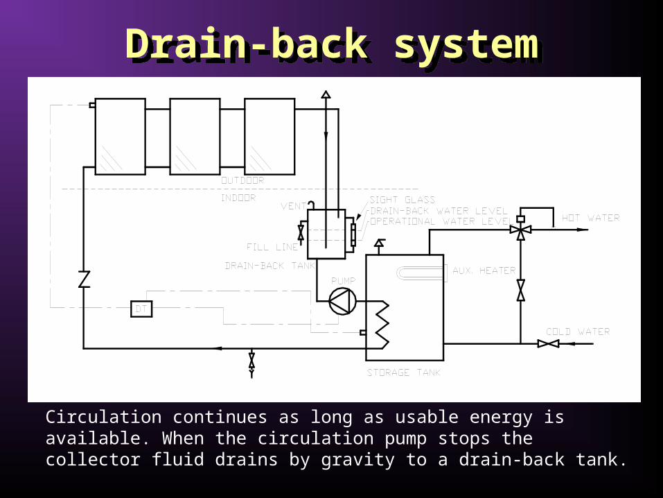
Drain-back systemDrain-back system
Circulation continues as long as usable energy is available. When the circulation pump stops the collector fluid drains by gravity to a drain-back tank.
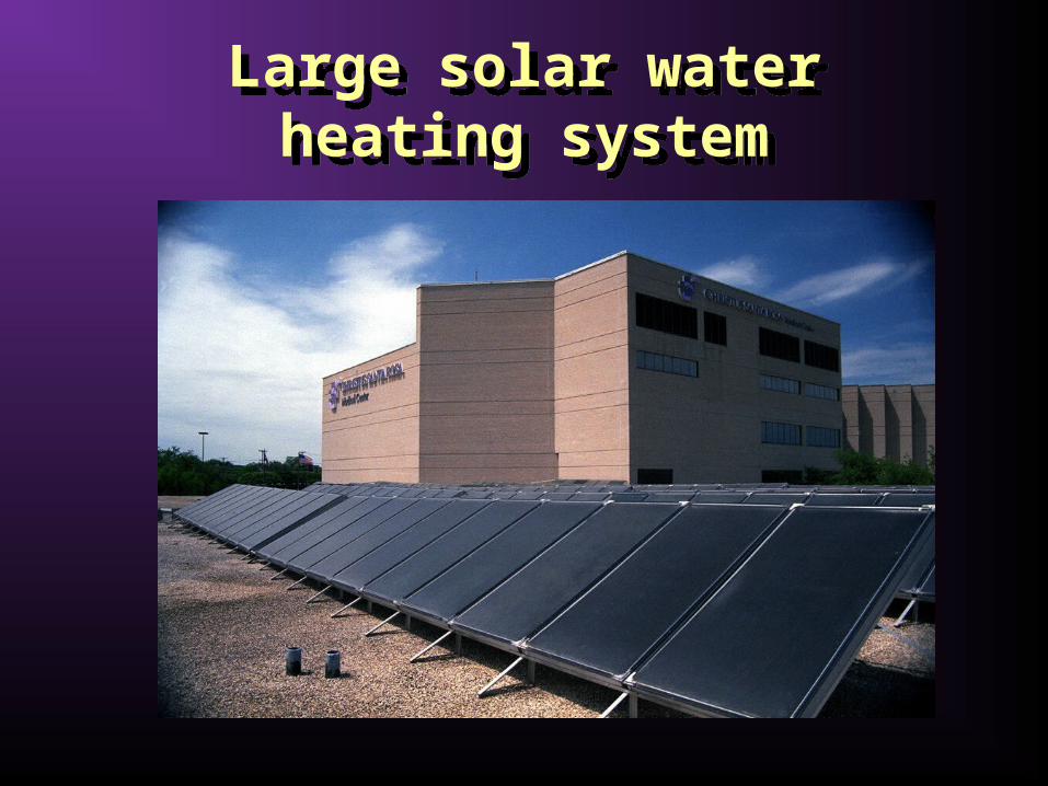
Large solar water heating system
Large solar water heating system

Air systemsAir systems
Air systems are indirect water heating systems that circulate air via ductwork through the collectors to an air-to-liquid heat exchanger. In the heat exchanger, heat is transferred to the potable water, which is also circulated through the heat exchanger and returned to the storage tank.
The main advantage of the system is that air does not need to be protected from freezing or boiling, is non-corrosive, and is free.
The disadvantages are that air handling equipment (ducts and fans) need more space than piping and pumps, air leaks are difficult to detect, and parasitic power consumption is generally higher than that of liquid systems.

Air systemAir system

Solar Space Heating and Cooling
Solar Space Heating and Cooling
Space Heating and Service Hot Water
Air systems
Water systems
Solar Space Heating and CoolingSolar Space Heating and Cooling
The components and subsystems discussed so far may be combined to create a wide variety of building solar heating and cooling systems.
Active solar space systems use collectors to heat a fluid, storage units to store solar energy until needed, and distribution equipment to provide the solar energy to the heated spaces in a controlled manner.
The load can be space cooling, heating, or a combination of these two with hot water supply.
In combination with conventional heating equipment solar heating provides the same levels of comfort, temperature stability, and reliability as conventional systems.

Space Heating and Service Hot WaterSpace Heating and Service Hot Water
It is useful to consider solar systems as having five basic modes of operation, depending on the conditions that exist in the system at a particular time:
• If solar energy is available and heat is not needed in the building, energy gain from the collector is added to storage.
• If solar energy is available and heat is needed in the building, energy gain from the collector is used to supply the building need.
• If solar energy is not available, heat is needed in the building, and the storage unit has stored energy in it, the stored energy is used to supply the building need.
• If solar energy is not available, heat is needed in the building, and the storage unit has been depleted, auxiliary energy is used to supply the building need.
• The storage unit is fully heated, there are no loads to met, and the collector is absorbing heat-relief heat.
Air systemsAir systems
A schematic of a basic solar heating system using air as the heat transfer fluid, with pebble bed storage unit and auxiliary heating source is shown in next slide.
The various modes of operations are achieved by appropriate positioning of the dampers. In most air systems it is not practical to combine the modes of adding energy to and removing energy from storage at the same time.
Auxiliary energy can be combined with energy supplied from collector or storage to top-up the air temperature in order to cover the building load.
It is possible to bypass the collector and storage unit when auxiliary alone is being used to provide heat.

Schematic of basic hot air system
Schematic of basic hot air system

Detail schematic of a solar air heating system
Detail schematic of a solar air heating system

Water systemsWater systems
When used for both space and hot water production this system allows independent control of the solar collector-storage and storage-auxiliary-load loops as solar-heated water can be added to storage at the same time that hot water is removed from storage to meet building loads.
Usually, a bypass is provided around the storage tank to avoid heating the storage tank, which can be of considerable size, with auxiliary energy.

Detail schematic of a solar water heating system
Detail schematic of a solar water heating system
Solar RefrigerationSolar Refrigeration
Solar cooling can be considered for two related processes:
• to provide refrigeration for food and medicine preservation and
• to provide comfort cooling. Absorption systems are similar to vapour-
compression air conditioning systems but differ in the pressurisation stage.
The most usual combinations of fluids include lithium bromide-water (LiBr-H2O) where water vapour is the refrigerant and ammonia-water (NH3-H2O) systems where ammonia is the refrigerant.

Absorption systemsAbsorption systems
The pressurisation is achieved by dissolving the refrigerant in the absorbent, in the absorber section.
Subsequently, the solution is pumped to a high pressure with an ordinary liquid pump.
The addition of heat in the generator is used to separate the low-boiling refrigerant from the solution. • In this way the refrigerant vapour is compressed
without the need of large amounts of mechanical energy that the vapour-compression air conditioning systems demand.
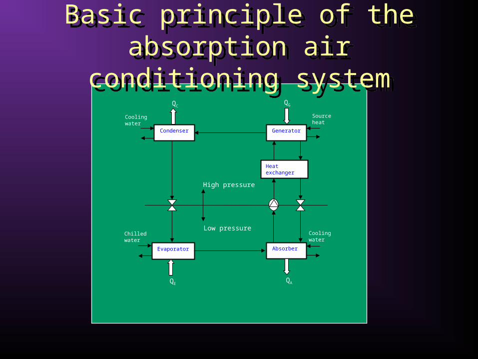
Basic principle of the absorption air conditioning system
Basic principle of the absorption air conditioning system
Condenser
Evaporator
Generator
Heat exchanger
Absorber
High pressure
Low pressure
QCQG
QEQA
Cooling water
Cooling water
Source heat
Chilled water
Industrial Process Heat Industrial Process Heat
Industrial Process HeatIndustrial Process Heat The central system for heat supply in most
factories uses hot water or steam at a medium temperature of about 150°C.
Hot water or low pressure steam at medium temperatures can be used either for preheating of water (or other fluids) used for processes (washing, dyeing, etc.) or for steam generation or by direct coupling of the solar system to an individual process.
In the case of water preheating, higher efficiencies are obtained due to the low input temperature to the solar system, thus low-technology collectors can work effectively.
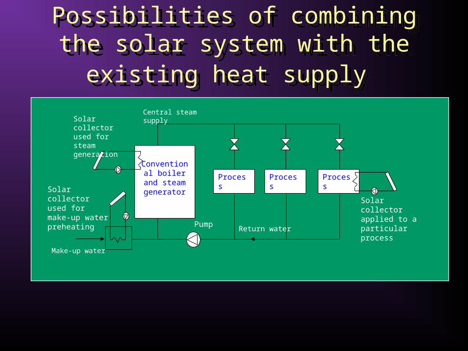
Possibilities of combining the solar system with the existing heat supply Possibilities of combining the solar
system with the existing heat supply
Conventional boiler and
steam generatorProcess Process Process
Return water
Central steam supply
Make-up water
Solar collector applied to a particular process
Solar collector used for make-up water preheating
Solar collector used for steam generation
Pump

PTCs for water heatingPTCs for water heating

Solar steam generation systems
Solar steam generation systems
Parabolic trough collectors are frequently employed for solar steam generation because relatively high temperatures can be obtained without any serious degradation in the collector efficiency.
Low temperature steam can be used in industrial applications, sterilisation, and for powering desalination evaporators.
Three methods have been employed to generate steam using parabolic trough collectors:
• The steam-flash concept.• The direct or in-situ concept.• The unfired-boiler concept.

The steam-flash steam generation concept
The steam-flash steam generation concept
In steam-flash concept, a pressurised water is heated in the collector and then flashed to steam in a separate vessel.

The direct steam generation concept
The direct steam generation concept
In direct or in-situ concept, a two phase flow is allowed in the collector receiver so that steam is generated directly.

The unfired-boiler steam generation concept
The unfired-boiler steam generation concept
In unfired-boiler concept, a heat-transfer fluid is circulated through the collector and steam is generated via heat-exchange in an unfired boiler.

Solar Desalination SystemsSolar Desalination Systems

Solar Desalination SystemsSolar Desalination Systems Water is one of the most abundant
resources on earth, covering three‑fourths of the planet's surface.
About 97% of the earth's water is salt water in the oceans; 3% of all fresh water is in ground water, lakes and rivers, which supply most of human and animal needs.
The only nearly inexhaustible sources of water are the oceans Their main drawback, however, is their high salinity.
It would be attractive to tackle the water-shortage problem with desalination of this water.
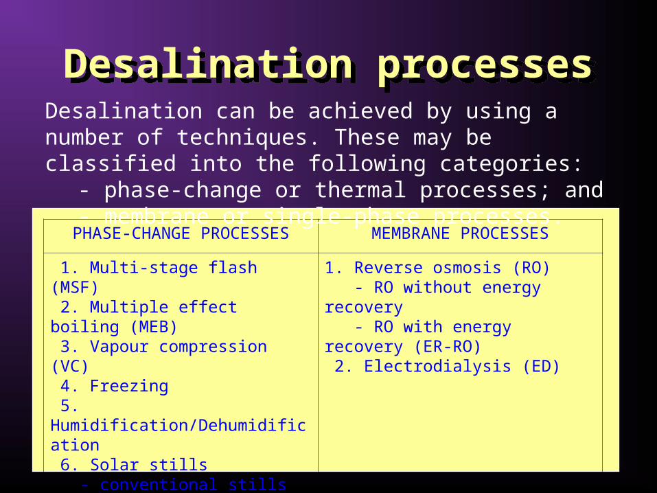
Desalination processesDesalination processes
PHASE-CHANGE PROCESSES MEMBRANE PROCESSES
1. Multi-stage flash (MSF) 2. Multiple effect boiling (MEB) 3. Vapour compression (VC) 4. Freezing 5. Humidification/Dehumidification 6. Solar stills - conventional stills - special stills - wick-type stills - multiple-wick-type stills
1. Reverse osmosis (RO) - RO without energy recovery - RO with energy recovery (ER-RO) 2. Electrodialysis (ED)
Desalination can be achieved by using a number of techniques. These may be classified into the following categories:
- phase-change or thermal processes; and - membrane or single-phase processes.

Intensive program: ICT tools in PV-systems Engineering
Solar StillsSolar Stills

Multiple Effect Boiling EvaporatorMultiple Effect Boiling Evaporator
Multiple Effect Stack (MES) type evaporator
This is the most appropriate type for solar energy applications.
Advantages:
Stable operation between virtually zero and 100% output even when sudden changes are made (most important).
Its ability to follow a varying steam supply without upset.
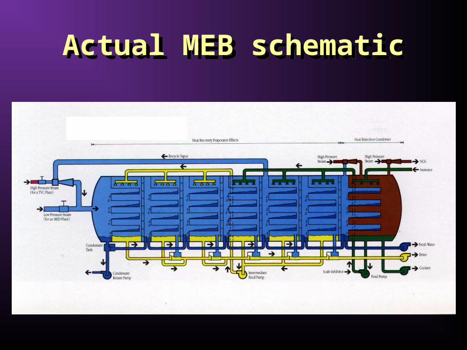
Actual MEB schematicActual MEB schematic

A photo of an actual MEB plant
A photo of an actual MEB plant

Actual MES plantActual MES plant

Solar Power systemsSolar Power systems
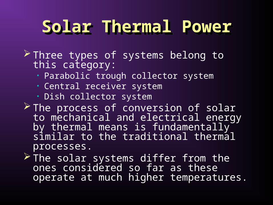
Solar Thermal PowerSolar Thermal Power
Three types of systems belong to this category:• Parabolic trough collector system• Central receiver system• Dish collector system
The process of conversion of solar to mechanical and electrical energy by thermal means is fundamentally similar to the traditional thermal processes.
The solar systems differ from the ones considered so far as these operate at much higher temperatures.

Schematic of a solar-thermal conversion system
Schematic of a solar-thermal conversion system

Typical Schematic of SEGS plantsTypical Schematic of SEGS plants

Parabolic Trough SystemParabolic Trough System

Parabolic trough collectorsParabolic trough collectors

Parabola detailParabola detail

Receiver detailReceiver detail

Central receiver systemCentral receiver system

Tower detailTower detail
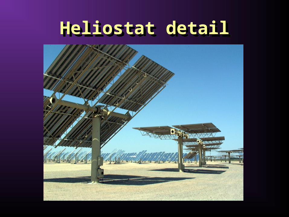
Heliostat detailHeliostat detail
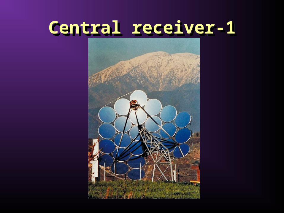
Central receiver-1Central receiver-1
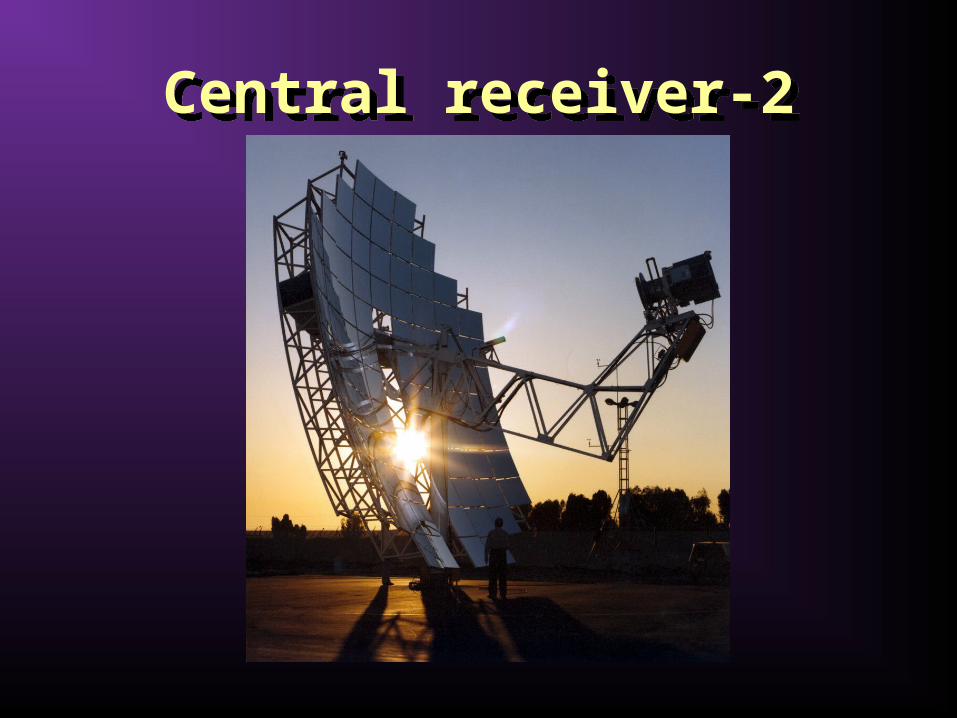
Central receiver-2Central receiver-2
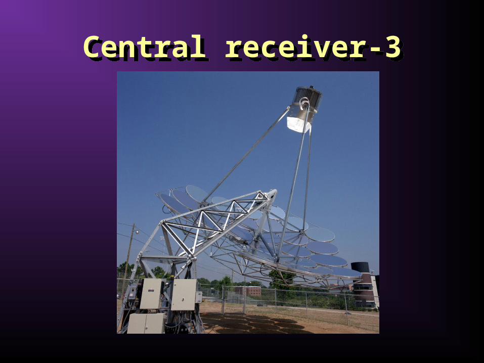
Central receiver-3Central receiver-3
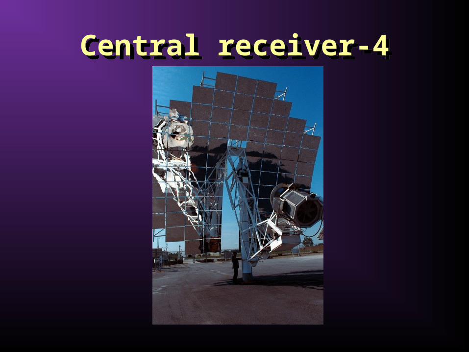
Central receiver-4Central receiver-4

Central receiver-5Central receiver-5
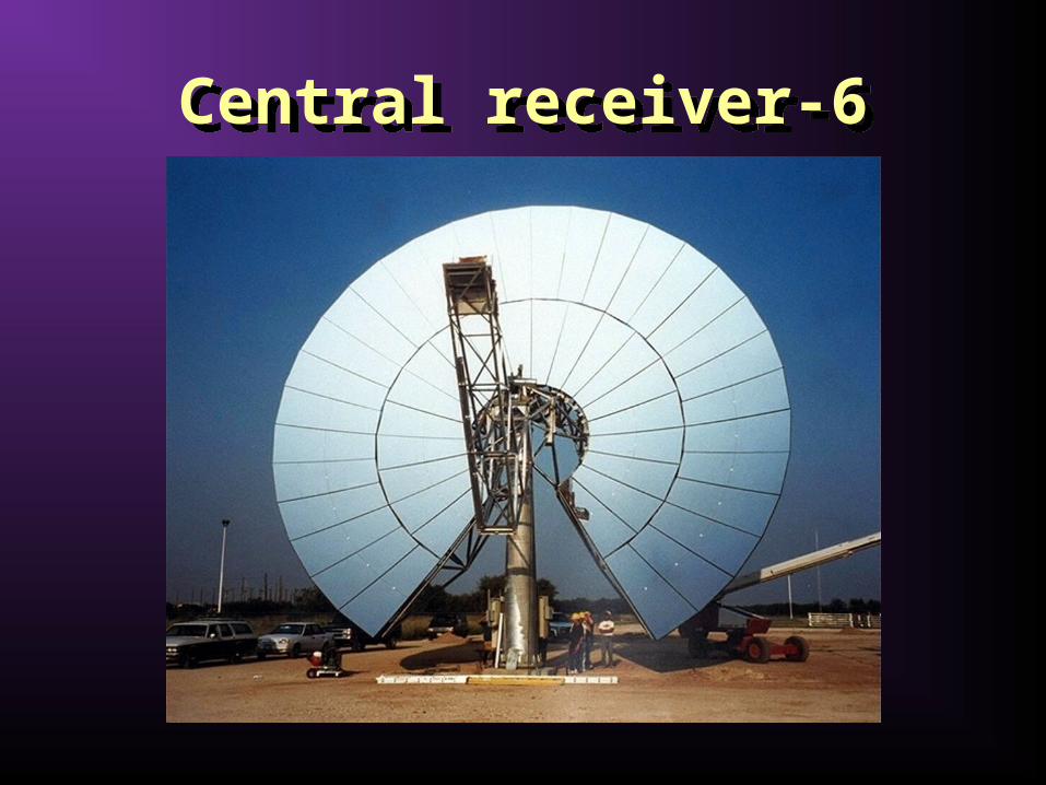
Central receiver-6Central receiver-6
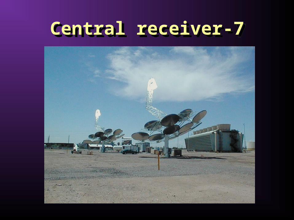
Central receiver-7Central receiver-7

Central receiver-8Central receiver-8

Solar energy should be given a chance if we want to protect the environment. We own it to our children, our grandchildren and the generations to come.
Solar energy should be given a chance if we want to protect the environment. We own it to our children, our grandchildren and the generations to come.
Thank you for your attention,
any questions please….