introduction to structural systems, construction...
TRANSCRIPT

INTRODUCTION TO STRUCTURAL SYSTEMS,
CONSTRUCTION METHODS AND MATERIALS
MODULE #2
Prepared by
Marcia C. Belcher, P.E.

Common type of construction for low rise structures (1-2 story).
Combination of: Bearing wall: vertical structural elements
which carry loads directly to foundations
Shear wall: panel that counters the effects of lateral load acting on a structure (wind, seismic, fluid pressure, etc.)
Bearing/Shear Wall Systems

Load Path of a Bearing Wall

Load applied to lateral wall Transmitted to the diaphragm
Load Path of Shear Walls
Transmitted from diaphragm to shear wall Reactions go to top of shear wall

Lateral walls are designed to resist bending forces
Shear walls are designed to resist shear and overturning

Load is transferred from shear wall to foundation
Sliding and overturning must be considered
How Shear Walls Relay Load to Foundations

Anchorage of Shear Walls

Example: Masonry Bearing/Shear Wall Construction
Masonry walls form the “box” (bearing/shear walls)
Metal bar joist/metal deck provide the diaphragm action in
the system

Vertical steel provides vertical flexural resistance.
◦ Cells containing reinforcement must be grouted solid to make steel effective.
Horizontal bars are strategically placed to form “bond beams.”
These are integral horizontal “beams” that are placed to increase the horizontal flexural strength of the wall.
Reinforcement of Masonry Bearing/Shear Walls

Typical construction types: Wood
Masonry
Reinforced Concrete
Light Gage Metal Studs (Cold Formed Steel)
Bearing/Shear Wall Systems

Braced frames use trussing (triangulation) to resist sideways forces on buildings.
Trussing is formed by inserting diagonal members into rectangular areas of a frame.
This stabilizes the frame against sideway forces from earthquakes and wind.
Concept: Braced Frames

The frame shown is laterally unstable in the present configuration.
Example of 2D Frame

Different bracing configurations to resist the load
Diagonal X-brace Knee brace
Example of 2-D Frame

2-D Frame: Other Bracing Configurations

Common roofing systems used in both bearing/shear wall and steel-frame type construction.
Can you identify lateral force resisting frames in this photograph?
Example of lateral bracing rather than rigid connections.
Metal Bar Joist: (Open Web Steel Joist)
.

Building systems can vary:◦ Moment resisting frames◦ Bearing/shear wall system
Typical methods:◦ Precast/Prestressed Concrete◦ Post-tensioned◦ Cast-in-place reinforced concrete
Reinforced Concrete Structures

Precast concrete is cast in a form which is then cured in a controlled environment, transported to the construction site and lifted into place.
Placement and handling methods are provided by the manufacturer.◦ Storage, blocking, lifting, etc.
Precast/Prestressed Concrete

Concrete element in which compressive forces are applied prior to loading.
◦ This counteracts the effect of subsequent loads
◦ Limits cracking and deflection
◦ Can achieve longer spans than practical for ordinary reinforced concrete
◦ Can be either pre-tensioned or post-tensioned
What is Prestressed Concrete?
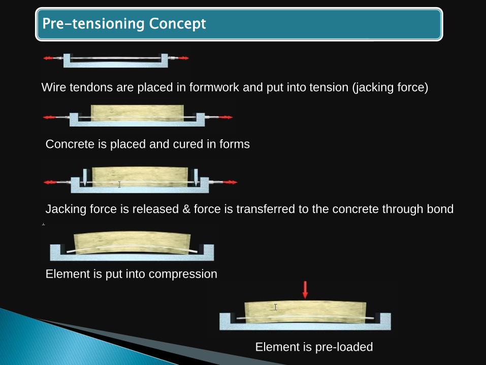
Pre-tensioning Concept
Wire tendons are placed in formwork and put into tension (jacking force)
Concrete is placed and cured in forms
Jacking force is released & force is transferred to the concrete through bond
Element is put into compression
Element is pre-loaded

Post-Tensioning Concept
Wire tendons in “sheaths” are place in formwork and concrete is poured/cured
Tendons are tensioned & end anchorage “locks” tendon
Element is put into compression by end anchorage
Element is loaded

Pre-tensioning is done at a precast manufacturing facility.
Precast concrete manufacturer must be certified by PCI's Plant Certification Program.
Post-tensioning is performed on the jobsite in cast-in-place applications.
Applications

Concrete that is supplemented with steel bars to resist: Tension
Compression
Shear
Cast-in-place Reinforced Concrete

Drawings & Specifications will provide:
Steel requirements:
Specified grade of reinforcing steel
Detailed drawings of size & location of bars
Lap splice location & length information
Type/location of welded splices & mechanical connections (restrictions similar to masonry)
Cast In Place Reinforced Concrete

Drawings & Specifications will provide:
Concrete requirements (per ACI):
Slump
Entrained air
Unit weight
Minimum compressive strength
Permitted admixtures
Cast In Place Reinforced Concrete