introduction to the underground injection control program · pdf filejanuary 2003 objectives...
TRANSCRIPT
January 2003
Introduction to the Underground Injection Control Program
1

January 2003
Drinking Water Academy
• Introductory modules – Overview of the Safe Drinking Water Act – Introduction to the EPA’s Source Protection
Programs – Introduction to the Underground Injection Control
Program – Introduction to the Public Water Supply
Supervision Program • Regulatory modules • Technical modules
• The Drinking Water Academy (DWA) develops and provides training to Federal, State and Tribal drinking water staff to help ensure that they will be adequately prepared to implement the provisions of the Safe Drinking Water Act (SDWA).
• This training course is one of four introductory courses that introduce you to the Safe Drinking Water Act and its major programs:
o Public water system supervision (PWSS);
o Source water protection; and
o Underground injection control (UIC).
• In addition to these introductory courses, the DWA provides training on other drinking water topics:
o SDWA regulations;
o Capacity development;
o Sanitary surveys;
o SDWIS; and
o Technical courses on source water, UIC and public water system issues.
• The DWA also provides skills training on risk communication and training delivery.
• For a complete list of the courses the DWA offers, visit our Web site at
http://www.epa/gov/safewater/dwa.html
2

January 2003
Objectives
• Describe the foundation of the Underground Injection Control program
• Describe the UIC program framework • Explain basic geology and injection
wells • Explain some of the challenges facing
today’s UIC program
3

January 2003
Objective 1
• Describe the foundation of the Underground Injection Control (UIC) program – Historical uses of injection wells – Regulatory timeline – Basic terminology – EPA’s mandate under SDWA – Mission of the UIC program
4
January 2003
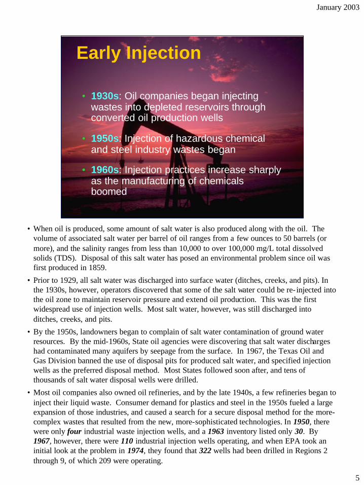
•• 1930s1930s: Oil companies began injecting wastes into depleted reservoirs through converted oil production wells
•• 1950s1950s: Injection of hazardous chemical and steel industry wastes began
•• 1960s1960s: Injection practices increase sharply as the manufacturing of chemicals boomed
Early Injection
• When oil is produced, some amount of salt water is also produced along with the oil. The volume of associated salt water per barrel of oil ranges from a few ounces to 50 barrels (or more), and the salinity ranges from less than 10,000 to over 100,000 mg/L total dissolved solids (TDS). Disposal of this salt water has posed an environmental problem since oil was first produced in 1859.
• Prior to 1929, all salt water was discharged into surface water (ditches, creeks, and pits). In the 1930s, however, operators discovered that some of the salt water could be re- injected into the oil zone to maintain reservoir pressure and extend oil production. This was the first widespread use of injection wells. Most salt water, however, was still discharged into ditches, creeks, and pits.
• By the 1950s, landowners began to complain of salt water contamination of ground water resources. By the mid-1960s, State oil agencies were discovering that salt water discharges had contaminated many aquifers by seepage from the surface. In 1967, the Texas Oil and Gas Division banned the use of disposal pits for produced salt water, and specified injection wells as the preferred disposal method. Most States followed soon after, and tens of thousands of salt water disposal wells were drilled.
• Most oil companies also owned oil refineries, and by the late 1940s, a few refineries began to inject their liquid waste. Consumer demand for plastics and steel in the 1950s fueled a large expansion of those industries, and caused a search for a secure disposal method for the more-complex wastes that resulted from the new, more-sophisticated technologies. In 1950, there were only four industrial waste injection wells, and a 1963 inventory listed only 30. By 1967, however, there were 110 industrial injection wells operating, and when EPA took an initial look at the problem in 1974, they found that 322 wells had been drilled in Regions 2 through 9, of which 209 were operating.
5

January 2003
•• 19681968: Hammermill Paper Company’s leak : Hammermill Paper Company’s leak suspected to cause contamination five miles suspected to cause contamination five miles awayaway
•• 19751975: Velsicol Chemical Company injection : Velsicol Chemical Company injection well determined to have contaminated an well determined to have contaminated an underground source of drinking waterunderground source of drinking water
Cause for ConcernCause for Concern
• The awareness of the importance of ground water began with the expansion of population into the suburbs in the 1960s. The only water supply available in many new suburbs was ground water, but the increase in drilling activity revealed that many aquifers were already contaminated with salt water, due to surface disposal of oil wastes. As a result, ground water pollution-related lawsuits became common in municipal and state courts, and the frequency of citizen complaints to state agencies and legislators increased tenfold, as measured in Texas, from 1955 to 1970.
• Responding to constituents' needs and complaints, State legislators began to create pollution-related water and ground water agencies by the mid-1960s, such as the Water Pollution Control Board in Texas. Since 80 percent of industria l injection wells were located in Texas, by 1969 the Water Pollution Control Board had developed an injection well regulatory program, in addition to its counterpart in the Oil and Gas Division.
• In addition to the regulatory attention caused by the increase in the use of injection technology for industrial waste disposal, there were two high-profile pollution cases that attracted national headline attention.
o An industrial waste injection well at Hamermill Paper was improperly sited in an over-pressured injection zone, and injection pressure caused noxious waste to flow uncontrolled out of an abandoned borehole five miles away, destroying the Michigan Union War Veteran's Memorial Cemetary and polluting Lake Erie.
o Another pollution incident involved a well at a Velsicol Chemical plant in Arkansas, which contaminated a USDW and caused health problems among residents.
6

January 2003
Regulatory Timeline
Early State programs to regulate ground water discharges
19721930s 1960s
States actively involved in ground water pollution issues
1974
SDWACWA
First Federal UIC regulations
1980
• The sequence of events leading to today’s Underground Injection Control program began with State programs.
• Although as early as the 1930s a few States had regulations concerning discharges to ground water, the regulations were primarily concerned with communication with surface water or subsurface oil reservoirs. As noted above, the mid-1960s found State agencies actively involved with ground water pollution issues.
• Federal authority for ground water and injection wells began in 1972. Although ground water was not specifically addressed by the Clean Water Act of 1972, Congress required that, in order to qualify for participation in the National Pollutant Discharge Elimination System (NPDES) permitting program, States must have adequate authority to issue permits that control the “disposal of pollutants into wells.”
• In 1974, with the enactment of the Safe Drinking Water Act, the Federal government took an active role in underground injection control. In response to the 1974 Act, EPA promulgated the UIC regulations in 1980. Since 1980, more than 150 Federal Register notices have been published regarding UIC, including additional regulations, amended regulations, explanations of procedures, and guidance.
• SDWA was significantly amended two times since 1974: in 1986 and 1996. In addition, there were two sets of minor amendments that affected the UIC program in 1977 and 1980. The UIC program was EPA’s major tool to protect ground water until the 1986 Amendments. In 1986, Congress created a larger Federal role in the protection of all ground water from sources other than underground injection.
7
January 2003
Mission of the UIC Program • The UIC program’s mission is to protect
underground sources of drinking water
from contamination by regulating the
construction and operation of injection
wells
• Injection into the subsurface is one of the primary means of disposing of liquid wastes in the United States. More than 400,000 injection wells are known to be in operation, disposing of millions of gallons of hazardous and nonhazardous fluid wastes.
• EPA implements the UIC mission by working with States, Tribes and local officials.
• EPA and States regulate injection wells according to the type of waste the wells inject and how deep the waste is injected. More details on the breakdown of the wells is provided later in this training.
8

January 2003
Define Well and Underground Injection • Well: A bored, drilled, or driven shaft, or a
dug well or dug hole where the depth is greater than the largest surface dimension; or an improved sinkhole; or a subsurface distribution system
• Underground injection: Subsurface emplacement of fluids through a well
• The Safe Drinking Water Act (SDWA) is the primary statute that governs injection wells. During deliberations for SDWA in 1974, Congress recognized the existence of a wide variety of injection wells, and struggled to provide a statutory definition that might include all possible injection types and practices. Congress included the “deeper than wide” specification in order to distinguish injection wells from pits, ponds, and lagoons, which were the subject of a different Federal initiative.
• Thus, injection through a well is defined as the subsurface emplacement of fluids through a bored, drilled, or driven well or through a dug well where the depth of the dug well is greater than the largest surface dimension; or a dug hole whose depth is greater than the largest surface dimension; or an improved sinkhole; or a subsurface distribution system.
• The definition of a UIC well was updated in December 1999, and the new definition makes it clear that many systems not typically thought of at first as a “well” actually meet the definition. The updated definition includes systems such as field tile systems, large capacity septic systems, mound systems and leach beds.
9

January 2003
Define Aquifer and USDW
• Aquifer: eologic formation that is capable of yielding a significant amount of water to a well or spring
• Underground source of drinking water: An aquifer or portion of an aquifer that – Supplies any public water system or contains a quantity of
ground water sufficient to supply a public water system, and
– Currently supplies drinking water for human consumption, or
– Contains fewer than 10,000 mg/L total dissolved solids and is not an exempted aquifer
G
• The definition of an underground source of drinking water (USDW) is codified in 40 CFR 146.3. The USDW definition ensures that potential sources of drinking water are protected as stringently as those sources currently used for drinking water. Application of a quality-based ground water standard rather than a usage-based standard provides for both protection of the ground water resource and public health. Ground water containing between 3,000 and 10,000 mg/L TDS is not suitable for human consumption, but may be used for livestock, irrigation, and industrial purposes, and can be treated for consumption if alternative water sources are not ava ilable.
• It is also important to note that the definition of an aquifer includes a formation capable of yielding a significant amount of water to a well. It does not mandate that the formation currently be used as a producing water source (i.e., it does not have to have drinking water wells completed into it).
• The definition of a transient non-community water system in SDWA’s Public Water System Supervision (PWSS) program can assist in establishing whether a formation yields enough water to be “significant.” If a formation can yield water enough to be regulated under the PWSS program, one would likely consider it “significant.” Many private wells produce enough water that they would meet the PWS production criteria, even though they do not meet that program’s criteria for number of people served.
10

January 2003
1974 SDWA - Basic UIC Concepts
• Requires EPA to promulgate regulations to protect drinking water sources from contamination through underground injection
• Defines:
– Underground injection
– Endangering drinking water sources
• Designed to be implemented by States
• SDWA required EPA to determine the need for and to promulgate regulations to protect drinking water sources from contamination through underground injection.
• Underground injection is defined in SDWA as “the subsurface emplacement of fluids by well injection.” This term does not include the underground injection of natural gas for storage.” SDWA also states that underground injection “endangers drinking water sources if such injection may result in the presence in underground water which supplies or can be reasonably expected to supply any public water system of any contaminant, and if the presence of such contaminant may result in such system’s not complying with any national primary drinking water regulation or may otherwise adversely affect the health of persons.” (see SDWA Section 1421(d)(2)). In other words, if an aquifer (which meets certain requirements described later in this module and is called a “USDW”) that is likely to be used for drinking water receives a contaminant by an injection well and the contaminant may cause a primary drinking water violation, the well is endangering the USDW.
• Following the model of the National Pollutant Discharge Elimination System (NPDES) program in the Clean Water Act, SDWA designed the UIC program to be implemented by the States. Section 1422 of SDWA provides for program delegation to the States, with accompanying grants to fund the creation and operation of UIC agencies. EPA provides oversight of State primacy agencies, and in States that choose not to assume the program, operates the program itself (i.e., direct implementation).
11

January 2003
1974 SDWA -EPA Requirements • Mandates that EPA:
– Not interfere with oil and gas production – Consider varying geologic, hydrologic, or
historical conditions – Avoid promulgating regulations that would
unnecessarily disrupt existing State programs
• During deliberations for SDWA, there was concern that injection regulation at the Federal level would contradict existing State programs or cause oil and natural gas production costs to unnecessarily increase. Further, concern was expressed that the program might not address the fact that geology and hydrogeology is highly variable across the nation.
• In SDWA, Congress included a provision that EPA not interfere with oil and gas production. Section 1421(b)(2) requires that Federal regulations not prescribe requirements that interfere with or impede: 1) the underground injection of brine or other fluids that are brought to the surface in connection with oil or natural gas production (natural gas storage was added in 1980); or, 2) any underground injection for the secondary or tertiary recovery of oil or natural gas unless such requirements for either of the above are essential to assure that underground sources of drinking water will not be endangered by such injection. Section 1422(c) states that a State UIC program may not have requirements that interfere or impede oil or gas production.
• Congress also mandated that EPA accommodate existing State programs, and consider local geologic conditions. Geologic conditions and oil production practices varied widely from State to State. Thus, Congress cautioned EPA against a “one-size-fits-all” regulatory scheme, and mandated consideration of local conditions and practices. Section 1421(b)(3)(A) requires that UIC regulations permit or provide consideration of varying geologic, hydrological, or historical conditions in different States and in different areas within a State. Section 1421(b)(3)(B)(i) requires that to the extent feasible, EPA must avoid promulgating requirements that would unnecessarily disrupt State UIC programs already in effect and being enforced in a substantial number of States.
12

January 2003
SDWA Changes From 1974 To Present
• Addition of section 1425 applicable to oil and gas related wells in 1980
• Additional requirements for hazardous waste UIC wells in 1986
• Expanded ground water protection focus in 1986
• SDWA was amended in 1977, 1979, 1980 and again in 1986. Additionally, Congress re-authorized and amended SDWA in 1996. Many of the changes to the Act over time were focused on procedures to be followed by EPA and/or State UIC programs. Some very significant impacts were felt in the program, however, when Section 1425 was added in 1980.
• Section 1425 allows a State to obtain primacy from EPA for oil and gas related injection wells, without being required to adopt the complete set of applicable Federal UIC regulations. The State must be able to demonstrate that its existing regulatory program is protecting USDWs without the State regulations being as stringent as Federal rules.
• The 1986 amendments included the addition of a new set of more stringent requirements for deep injection wells that dispose of hazardous wastes. These requirements are discussed later. Amendments made in that year also expanded EPA’s responsibility for ground water protection and stewardship. In response to the statutory amendments, EPA developed the Ground Water Protection Program. This program does not have regulations, but conducts outreach and assists States in designing and implementing wellhead protection (WHP) programs. The WHP programs offer a cost-effective means of protecting ground water, and provide an excellent opportunity to educate communities on the UIC Program’s priorities.
• Congress required EPA to assess the UIC program’s progress since 1974 as part of the 1986 amendments as well. One focal point was to assess the impact of shallow injection wells. EPA responded with the 1987 Report to Congress, which is often referenced in EPA UIC reports and other documents.
13

January 2003
Objective 2
• Describe the UIC program framework – UIC program terminology – Structure of the UIC program – Other Federal statutes affecting UIC
14

January 2003
UIC Terminology
• Primacy
• Primacy State or Tribe
• Direct Implementation State or Tribe
• Code of Federal Regulations
• Primacy - Primary enforcement authority. EPA may grant States and Tribes primacy for all or parts of the UIC program. For example, a State may only have primacy for certain types (or classes) of injection wells. If a State does not have primacy, the EPA Region directly implements the program and retains primary enforcement authority.
• Primacy State or Tribe- A State or Tribe with primary enforcement authority for one or more types (classes) of injection well.
• Direct Implementation (DI) State or Tribe - A State or Tribe that does not have primary enforcement authority and in which the EPA Region directly implements the UIC program.
• Code of Federal Regulations (CFR) - Environmental regulations are codified in Title 40 of the CFR. The Federal UIC regulations are found at 40 CFR Parts 144 - 148.
15

January 2003
Structure of the Program: Primacy Requirements • Must promulgate requirements that are
at least as stringent as EPA’s: – Prohibit injection unless authorized by rule
or permit – Prevent underground injection that
endangers drinking water sources – Implement requirements for inspection,
monitoring, recordkeeping, and reporting
• May be more stringent than EPA’s regulations
• When a State or Tribe has primacy for the UIC program, it means that the State or Tribe has the lead responsibility for administering and enforcing the program and must have the staff and funding to run the program. Upon receipt of primacy, a State must implement all the requirements specified in the EPA - State agreement, and track the program’s progress to demonstrate that the agreement is being appropriately followed.
• Congress defined the requirements that must be met to qualify for primacy, methods of application for primacy, and standards of operation necessary to retain primacy. Section 1422 of SDWA lists these requirements and EPA expanded on these requirements in regulations in 40 CFR Part 145.
o A State or Tribe must adopt statutes and regulations that are at least as stringent as the Federal regulations and receive program approval from the EPA Administrator.
o However, States or Tribes can obtain primacy for strictly oil and gas related wells (under Section 1425 of SDWA) if the State program is demonstrated to be effective in protecting USDWs even if the State regulations do not match all the Federal regulations.
• Congress authorized grants to fund primacy States’ UIC programs. The grant allocation is tied to injection well usage in each primacy State. States without primacy, where EPA administers the UIC program, do not receive this funding.
• Congress provided that States and Tribes may adopt regulations that are more stringent than Federal rules. Numerous States have adopted requirements that exceed the Federal standards. 16

January 2003
Structure of the Program: UIC Primacy Delegation
• The map above illustrates the status of program delegation nationally as of June 2001. EPA has delegated primacy for all well classes to 34 States; it shares responsibility in six States; and implements a program fo r all well classes in ten States. The Agency has also delegated primary enforcement responsibility to three territories.
• Native American Tribes follow the same rules as States to obtain primacy, if they are a “Federally Recognized Tribe” and have been designated for “treatment similar to a State.” To date, the UIC program in all Native American lands is implemented by EPA.
• The primacy application process is lengthy, and requires a great deal of communication between the EPA Region and the State or Tribe submitting the application.
• Section 1422(a) requires EPA to make a list of States that need UIC programs. That list is in 40 CFR Part 147. This part of the CFR can assist you in determining the status of a particular UIC program in a given geographic area. However, for the latest information, contact the EPA Regional Office UIC staff.
17

January 2003
Structure of the Program: UIC Regulations • 40 CFR Part 35 - State and Tribal
Financial Assistance
• 40 CFR Part 124 - Public Participation Requirements
• 40 CFR Part 144 - Permitting and Program Requirements
• 40 CFR Part 145 - Requirements and Procedures for State Program Approval
• The UIC regulations are found in 40 CFR Parts 144, 145, 146, 147, and 148. Parts 35 and 124 include procedural requirements for all EPA Programs. Part 124, Public Participation Requirements, is significant as it describes the requirements for public notification of pending permits and public comment periods, as well as other public participation requirements.
• Part 144, Underground Injection Control Program, describes the general requirements of the UIC Program, authorizes certain types of wells by rule, and defines procedures for applying for a UIC permit or submitting inventory information. This section also describes conditions applicable to all UIC permits and establishes minimum permit conditions, such as construction, operation, testing, and monitoring requirements. Subpart F establishes procedures for ensuring financial responsibility for plugging and abandoning (i.e., closing) wells.
• Part 145, State UIC Program Requirements, describes the requirements that State programs applying for primacy must meet and the method for obtaining program approval, such as the required elements of a State program submission. It also describes EPA’s procedures and criteria for reviewing State applications for primacy, including procedures by which EPA can approve, review, or withdraw primacy.
18

January 2003
Structure of the Program: UIC Regulations
• 40 CFR Part 146 - UIC Criteria and Standards
• 40 CFR Part 147 - State UIC Programs
• 40 CFR Part 148 - Hazardous Waste Injection Restrictions
• Part 146, UIC Program: Criteria and Standards, contains the technical criteria and standards for the various classes of underground injection wells. A subpart devoted to each UIC well class describes construction, operating, monitoring, and reporting requirements, along with information to be considered in determining whether to grant a permit. Other standards and requirements specific to well types are included in this portion of the CFR.
• Part 147, State UIC Programs describes the provisions of the State primacy programs. Each subpart of Part 147 is devoted to an individual State; it outlines which aspects of the UIC program are overseen by EPA, and which are delegated to the State. It incorporates by reference all pertinent State rules and regulations so as to allow EPA to take direct enforcement action in primacy States.
• Part 148, Hazardous Waste Injection Restrictions, identifies hazardous wastes that are restricted from disposal into deep hazardous waste injection wells. The requirements of this Part will be discussed in the well class-specific discussion later in this course. Briefly, this Part outlines the standards and procedures by which Class I hazardous waste facility operators may petition to dispose of restricted hazardous wastes. Part 148 requires operators of Class I hazardous waste injection wells to demonstrate with reasonable certainty that the hazardous components of their wastewaters will not migrate from the authorized injection zone.
19

January 2003
Structure of the Program: Authorization by Rule and Permitting • Some wells may be authorized by rule;
permit not required if comply with basic requirements
• Some well owners or operators must apply for permits to drill and to operate
• All wells must submit inventory data
• All wells are subject to non-endangerment standard
• When a well is authorized by rule, it means that the owner/operator does not have to apply to EPA or the State for a permit as long as he complies with the requirements of the rule. Some UIC well types require a permit to drill before the well may be installed, and a permit to operate before the well may be used. The owner or operator must apply for a permit from EPA or the primacy State. The permit application requirements, as well as conditions imposed in a permit, vary based on the type of well, material injected, geology of the area and other factors.
• Owners or operators of all UIC wells, whether the well is subject to permitting or is authorized by rule, are required to submit basic inventory information to the appropriate regulatory agency. Additionally, all wells are prohibited from endangering USDWs, known as the “non-endangerment standard”. (See page 11 for definition.)
20

January 2003
Structure of the Program: Inspections • EPA is authorized to inspect any facility
subject to the UIC program
• Types of inspections vary, based on status of wells and facility
• EPA UIC inspector training available
• All UIC wells are subject to inspections from State or Federal UIC program personnel. The frequency of inspections, and the level of scrutiny of the inspection vary with the well status, type of well, type of waste injected, history of compliance, and other factors.
• The primary goal of a UIC inspection is to assemble information that can be used to determine compliance with permit conditions and/or other regulatory requirements. Inspections vary in focus from pre-operations and construction, to routine compliance and operation, to well testing or well closure.
• The EPA UIC Inspector Training Course offers more detail on inspections, and all personnel responsible for evaluating UIC compliance are encouraged to take this course. Through that course, you will learn about the various inspections conducted, what transpires during the inspections, proper documentation of each inspection type, and how to respond to various noncompliance situations that may be encountered during inspections.
21

January 2003
Structure of the Program: Enforcement • Primacy agencies and Regional DI
programs
• Office of Enforcement and Compliance Assurance
– Office of Regulatory Enforcement
– Office of Compliance
• State primacy agencies and Regional DI programs typically take the lead on enforcement cases in primacy States and DI States, respectively.
• The Office of Regulatory Enforcement (ORE) serves as the focal point for all enforcement actions of the UIC program. ORE’s Water Enforcement Division (WED) works with technical staff (primarily in the Regions) to develop enforcement cases against facilities meriting enforcement action. This office also develops national enforcement policy and guidance.
• The Office of Compliance (OC) does not pursue actual enforcement activities, but develops and supports initiatives to assist well operators and owners in understanding requirements and achieving compliance. This may take the form of training, database development and maintenance, outreach to the regulated community, the development of “Sector Notebooks” (primers describing industries such as automotive, oil and gas, railroads), or other activities.
• Each State has its own enforcement procedure, which must meet certain Federal requirements and which is described and approved through the primacy process.
22

January 2003
Structure of the Program: Enforcement • Enforcement tools available include:
– Informal enforcement actions – Formal enforcement actions (section 1423) – Others (emergency authority)
• The most successful State efforts to achieve compliance are often preventive efforts and informal enforcement actions. Preventive efforts are aimed at notifying and educating an operator about requirements, and can result in avoiding critical problems. Examples of preventive efforts include guidance documents, reminder letters, on-site meetings and technical assistance.
• Informal actions are generally taken for minor violations such as failure submit minor data points from monitoring. Examples of informal actions include notices of violation; on-site meetings; and technical assistance.
• States and EPA generally reserve their strongest enforcement tools for owners and operators who have not been responsive to enforcement actions, facilities whose vio lations pose significant public health threats, or facilities with a history of noncompliance. These formal actions include administrative orders, issued at the agency level. An administrative order includes an opportunity for a public hearing and may include penalties up to $25,000 per day of violation. States may bring civil actions before a State court, which may issue Judicial Decrees that may also include penalties. States may refer enforcement actions to EPA as a last resort when State resources cannot address the issue or when previous State efforts have not been successful. EPA can bring an administrative action or can refer the case to the Department of Justice for civil (or criminal) action. EPA and the State may bring joint enforcement actions. EPA may also bring an independent enforcement action in a primacy State, after appropriate notice, if the State fails to take enforcement action.
• EPA has emergency powers under section 1431 if there is an “imminent and substantial endangerment” to a USDW. EPA may issue orders, including orders to provide an alternative source of drinking water, and commence a civil action, including a restraining order or a permanent or temporary injunction.
23
January 2003
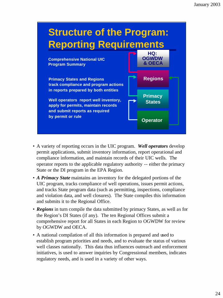
Structure of the Program: Reporting Requirements
Well operators apply for permits, maintain records and submit reports as required by permit or rule
Primacy States and Regions track compliance and program actions in reports prepared by both entities
Comprehensive National UIC Program Summary
Operator
Primacy States
Regions
HQ: OGWDW & OECA
report well inventory,
• A variety of reporting occurs in the UIC program. Well operators develop permit applications, submit inventory information, report operational and compliance information, and maintain records of their UIC wells. The operator reports to the applicable regulatory authority -- either the primacy State or the DI program in the EPA Region.
• A Primacy State maintains an inventory for the delegated portions of the UIC program, tracks compliance of well operations, issues permit actions, and tracks State program data (such as permitting, inspections, compliance and violation data, and well closures). The State compiles this information and submits it to the Regional Office.
• Regions in turn compile the data submitted by primacy States, as well as for the Region’s DI States (if any). The ten Regional Offices submit a comprehensive report for all States in each Region to OGWDW for review by OGWDW and OECA.
• A national compilation of all this information is prepared and used to establish program priorities and needs, and to evaluate the status of various well classes nationally. This data thus influences outreach and enforcement initiatives, is used to answer inquiries by Congressional members, indicates regulatory needs, and is used in a variety of other ways.
24

January 2003
Structure of the Program: Public Involvement in UIC • SDWA mandates public involvement
• Opportunities – FACA-chartered National Drinking Water
Advisory Council for Class V regulation and study
– Public hearings for program revisions, permits, permit appeals, and aquifer exemption
– Public information meetings may be held for permit decisions and other Agency actions
• The 1996 reauthorization of SDWA included changes that placed increased focus and importance on public involvement. In the UIC program, there are several ways that the public is involved.
• In 1996, EPA assembled the National Drinking Water Advisory Council (NDWAC) working group to make recommendations on regulatory development and a study being conducted for one type of injection well. The working group was designed to represent environmental groups, industry, and other stakeholders.
• In addition, according to Section 1421(a)(2) the EPA Administrator must provide for public hearings before promulgating UIC regulations. Section 1422(b)(1) requires State primacy agencies to provide for public hearings before submitting a primacy application, including applications for rule and primacy description updates. Furthermore, 40 CFR Part 124 requires public notice of permits and public hearings in some cases. Public hearings allow individuals to formally enter their comments into the record of the action being considered by EPA.
o Public information meetings or sessions may be held in some circumstances to allow the public to ask questions of the Agency. These information sessions provide opportunities to educate interested parties on the UIC issues at hand and on how EPA oversees UIC well operations.
25

January 2003
Other Federal Statutes Affecting UIC • RCRA - site regulation divided into
above ground and below ground surface – Hazardous waste sites – Underground storage tanks
• CERCLA - program overlap similar to RCRA
• Non-UIC Federal regulations affect UIC wells in some cases. For example, for wells disposing of hazardous waste the Resource Conservation and Recovery Act (RCRA) has responsibility for hazardous waste issues above ground related to the well (such as treatment, storage, and processing facilities), whereas UIC regulates everything down-hole, i.e., downstream of the wellhead.
• The hazardous waste program and the Underground Storage Tank (UST) program, also under RCRA, require corrective action at sites contaminated by leaking USTs or hazardous waste treatment, storage or disposal facilities. Cleanup may involve installing UIC wells as part of the overall treatment system.
• This same split of responsibility applies to sites where actions are taken under the Comprehensive Environmental Response, Compensation, and Liability Act (CERCLA or Superfund).
• While the regulations and EPA programs are divided in this way, the public sees the site as one EPA issue. This emphasizes the importance of cross-program coordination where multiple sets of Federal and/or State regulations overlap in jurisdiction. If hazardous waste is illegally disposed into a UIC well, the hazardous waste and underground injection programs need to work closely on an enforcement case to ensure that all regulatory requirements for clean-up and site closure are achieved, and to ensure that the public hears the Agency speaking with one voice on the site.
26

January 2003
Other Federal Statutes Affecting UIC • Toxic Substances Control Act - PCB
issues • Clean Water Act - storm water,
antidegradation • Emergency Planning and Community
Right-to-Know Act - Toxic Release Inventory
• Federal Land Policy and Management Act - mining site requirements on Federal lands
• The Toxic Substances Control Act (TSCA) sets standards for disposing of polychlorinated biphenyls (PCBs) and limits land disposal of PCB wastes.
• The Clean Water Act (CWA) may affect the UIC program in a variety of ways. Guidance issued by the Office of Wastewater Management (OWM) promotes use of storm water drainage wells (a type of UIC well), and antidegradation requirements may encourage regulated entities to seek other methods of discharging waste waters, including injection. State CWA-authorized programs may issue subsurface discharge permits that do not consider or may not be consistent with UIC regulatory requirements.
• The Toxics Release Inventory (TRI) is an annual report of toxic chemical pollution released into the environment by businesses throughout the country, required under Section 313 of the Emergency Planning and Community Right-to-Know Act (EPCRA). Underground injection of toxics is considered a release and must be reported under the TRI.
• Bureau of Land Management (BLM) implements the Federal Land Policy and Management Act of 1976. This statute regulates mining sites on public lands. These sites may have UIC wells.
• In addition, UIC regulations require that EPA consider numerous Federal laws when issuing UIC permits, including Section 7 of the Wild and Scenic Rivers Act, Section 106 of the National Historic Preservation Act , Section 7 of the Endangered Species Act, Section 307(c) the Coastal Zone Management Act, and the Fish and Wildlife Coordination Act. These laws are considered to insure that injection operations do not adversely affect other important nearby resources and sensitive areas.
27

January 2003
Objective 3
• Explain basic geology and injection wells – Basic hydrogeology and well technology – Pathways of contamination – Classes of wells and UIC regulatory
scheme
28

.
January 2003
UIC Wells: Basic Geology
Su
bsu
rfac
e
Clay
Sand
Sand
Clay
• The earth's crust (the upper 20 miles of the planet) is made of rock and rock and mineral fragments, such as sand and clay. The sand and clay materials were deposited as approximately horizontal layers by the earth's natural processes, primarily sedimentation by the interaction of rivers and oceans.
o Rivers and oceans tend to produce deposits of loosely packed sand (in high-energy environments such as beaches and sandbars) and tightly packed clay (in low energy environments such as near-shore lagoons and deep ocean).
o The subsurface in most areas of the United States is typified by alternating layers of sand and clay, usually tens to hundreds of feet thick, that represent the long-term cycles of sediment deposition by rivers and oceans. Multiple layers exist in the subsurface because as more sediment is piled on top, the region subsides. Some regions, such as the Gulf Coast, feature as much as 25,000 feet of buried, alternating sand and clay layers. Sediments are gradually compacted as they are buried further, and some are eventually cemented by natural processes into harder rocks.
• Although sediment layers in the Gulf Coast region are relatively consistent, this may not be the case in every geologic region. The subsurface in some regions may have been modified by tectonic processes such as uplift and deformation, local and regional faults, and/or discontinuity of layers. The consistency and predictability of subsurface conditions are the paramount features of effective injection and confining zones, and not all regions are suitable for safe injection. The Gulf Coast is an excellent geologic setting for the use of injection wells, and about 70 percent of deep injection wells are located there.
29

.
January 2003
Basic Geology C
lay
San
d
Cla
y
Low Permeability-Confining Layer
High Permeability/High Porosity
Low Permeability -Confining Layer
• Subsurface layers exhibit certain characteristics that are essential to our discussion. Sand layers consist of sand grains, and there are spaces (pores) between the grains. A layer with a high volume of pore spaces is said to possess high porosity. In most sand layers, the pores are connected such that fluids may easily move among the pores, and those layers are said to possess high permeability. An ideal injection zone should have sufficient thickness and high porosity (to allow storage of the injectate) and high permeability (to allow the injectate to freely enter and move within the zone).
• Conversely, clay layers are composed of tiny, plate- like particles, that are very impermeable, especially in the vertical direction. The ideal injection zone is also overlain and underlain by dense, impermeable clay layers, called shale, which act as confining layers. Effective confining layers do not allow injected fluids to escape the injection zone, and ideally isolate injected fluids almost indefinitely. How do we know this, besides field and laboratory tests? Oil and gas could not be concentrated in the subsurface and produced, if confining layers did not confine throughout geologic time.
30

-
January 2003
WATER TABLE
Brine - Salt Water (>10,000 TDS)
DR
Y
WE
T -
AQ
UIF
ER
US
DW
BR
INE
And Useable Quality Water (3,000-10,000 TDS)
Underground Source of Drinking Water Include: Drinkable Quality Water (<3,000 TDS)
• The earth’s crust is saturated with water, like a wet sponge. The surface of the earth is either wet (oceans, lakes, swamps) or dry (terra firma, dry land). On land, water exists at some depth below land surface, from 2 inches (south Louisiana) to 600 feet (Mojave desert). Water that exists beneath the land surface is called ground water. At some point below the surface, the pores of the rocks are completely saturated with water (the “water table”). A permeable layer whose pores are saturated with water is called an aquifer.
• Water contains dissolved minerals, especially salt. The salinity of water is expressed as Total Dissolved Solids (TDS), measured as parts per million (ppm) or the equivalent milligrams per liter (mg/L). The salinity of drinking-quality water ranges from 0 to 3,000 mg/L TDS. Humans prefer water containing less than 500 mg/L, but many water supplies contain as much as 1,000 mg/L TDS. Water containing up to 3,000 mg/L can be consumed by livestock or used for crop irrigation. Because water that has a higher salinity than drinking water may be used for many other purposes (i.e., agricultural and industrial uses), we designate usable quality water as that containing from 3,000 to 10,000 mg/L TDS. Water containing in excess of 10,000 TDS is called brine, or simply salt water.
• Ground water increases in salinity with depth. On the Gulf Coast, drinking water exists from 5 feet to about 1,500 feet below land surface, usable quality water from about 1,500 feet to about 3,500 feet, and brine at about 7,000 feet contains about the same salinity as sea water (about 26,000 mg/L TDS). Below 20,000 feet, the water can be ten times as saline as sea water (over 200,000 mg/L TDS). In West Texas, drinking water exists in the interval from 150 to 350 feet below ground surface, and usable quality water extends to only about 500 feet. The depth to the water table, ground water salinity profile, and depth to the base of usable quality water are unique to each geologic region.
31

January 2003
USDW
USDW
Confining Layer (Low Permeability)
Confining Layer (Low Permeability)
Base ofLowermost USDW
• This slide provides a 3-dimensional perspective. Remember that there may be several USDWs in a particular region, each separated by a confining zone. These USDWs usually increase in salinity with depth. Some UIC references are to the “base of the lowermost USDW.”
• When wells inject fluids into a layer, the native water is displaced from the area around the well. Storage volume for the injectate is “created” by compressing the native water and expanding the injection layer, distributed over a huge area. The result is an increase in pressure within the layer. Thus, the ideal injection zone must also be laterally extensive and thick. In summary, the ideal injection zone:
o Is sufficiently thick;
o Has high porosity to allow storage of the injectate;
o Has high permeability to allow the injectate to freely enter and move within the zone; and
o Is overlain and underlain by dense, impermeable layers that act as confining layers.
• The ideal confining zone:
o Has low permeability, especially in the vertical direction; and
o Sufficient thickness to prevent upward movement of injected waste.
32

January 2003
Aquifer Exemption
• 40 CFR 144.16 allows EPA to exempt certain USDWs from SDWA protection
• Criteria:
– Contain oil or minerals
– Recovery is impracticable
– Contaminated
– Contain TDS greater than 3,000 mg/L
• SDWA also provides for exceptions to the USDW protection standard. EPA developed exemption criteria, application standards and procedures, and a public notification process to ensure that aquifer exemptions are thoughtfully considered and receive wide consensus. In some cases, operators apply for an aquifer exemption to the primacy State or Tribe, which forwards the State’s or Tribe’s recommendations to EPA. In Direct Implementation States and Tribes, the operator applies to EPA directly. Most aquifer exemptions are limited to a specific portion of an aquifer, and many are temporary and require aquifer restoration. Many aquifer exemptions have been denied.
• Most exempted aquifers contain significant mineral deposits or oil reservoirs that require injection methods for recovery. In many western states, however, the depth to the base of 10,000 mg/L TDS water is extreme, in some cases approaching 8,000 feet below land surface. On the far North Slope of Alaska, for example, EPA has determined that certain us able aquifers beneath the permafrost have greater value for secure waste disposal than as drinking water sources. This decision was based on the poor quality of the water (it may be usable for purposes other than drinking water), the remoteness and depth of the aquifers (from 2,000 to 7,000 feet below surface), plentiful surface water, and the extremely low population density (i.e., none.)
33

January 2003
Injection Well Technology 1st Step: Surface Casing
• Injection wells are used for a variety of purposes including waste disposal; enhancing recovery of oil, gas, or minerals; and storage.
• Most injection wells consist of a drilled hole and one or more concentric lengths (strings) of pipe, called casing or tubing depending on its diameter. Construction methods are borrowed from oilfield technology. The following series of slides explain the steps in construction of an injection well.
• Surface casing is the first casing installed in the well. A hole is drilled from the surface to below the base of the lowest aquifer containing 10,000 mg/L TDS water. The surface casing is installed in the borehole, and is sealed into the hole with cement.
• Cementing is the introduction, usually from the bottom-up, of neat Portland cement (not concrete) and mineral additives, that serve to seal the casing to the formations exposed in the borehole. Cement also protects the casing from corrosion and prevents movement of injectate up the borehole. Proper cementing provides a three to seven inch thick sheath around the casing.
• Surface casing protects the USDW from the effects of drilling, and provides the outermost layer of protection for the well. This casing is typically 8-1/2 to 12 inches in diameter, and extends from 150 to 1,500 feet in length.
34
January 2003
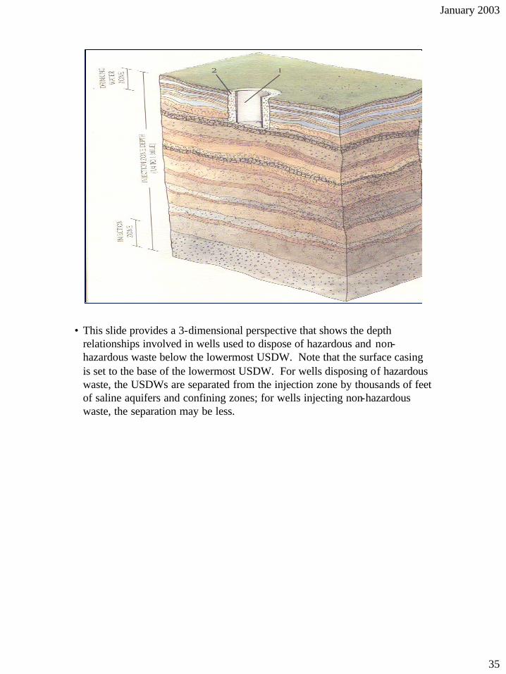
• This slide provides a 3-dimensional perspective that shows the depth relationships involved in wells used to dispose of hazardous and non-hazardous waste below the lowermost USDW. Note that the surface casing is set to the base of the lowermost USDW. For wells disposing of hazardous waste, the USDWs are separated from the injection zone by thousands of feet of saline aquifers and confining zones; for wells injecting non-hazardous waste, the separation may be less.
35

January 2003
2nd Step: Long-String Casing
• Long-string casing is installed within the surface casing - imagine a pipe within a pipe. The cementing plug is drilled out and drilling continues through the confining zone to the injection interval. The long-string casing is installed from the surface to (or through) the injection zone, and is sealed into the drill hole with cement.
• The long-string casing is then perforated to allow communication through the casing into the injection formation. Some wells may use screens instead of perforations.
• Long-string casing is typically 5-1/2 to 9-1/2 inches in diameter, and may range from 100 feet to over 10,000 feet in length.
36
January 2003
3rd Step: Tubing and Packer
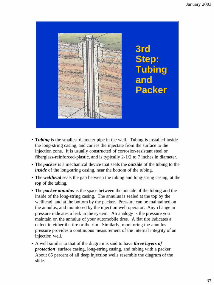
• Tubing is the smallest diameter pipe in the well. Tubing is installed inside the long-string casing, and carries the injectate from the surface to the injection zone. It is usually constructed of corrosion-resistant steel or fiberglass-reinforced-plastic, and is typically 2-1/2 to 7 inches in diameter.
• The packer is a mechanical device that seals the outside of the tubing to the inside of the long-string casing, near the bottom of the tubing.
• The wellhead seals the gap between the tubing and long-string casing, at the top of the tubing.
• The packer annulus is the space between the outside of the tubing and the inside of the long-string casing. The annulus is sealed at the top by the wellhead, and at the bottom by the packer. Pressure can be maintained on the annulus, and monitored by the injection well operator. Any change in pressure indicates a leak in the system. An analogy is the pressure you maintain on the annulus of your automobile tires. A flat tire indicates a defect in either the tire or the rim. Similarly, monitoring the annulus pressure provides a continuous measurement of the internal integrity of an injection well.
• A well similar to that of the diagram is said to have three layers of protection: surface casing, long-string casing, and tubing with a packer. About 65 percent of all deep injection wells resemble the diagram of the slide.
37

January 2003
External Pathways Not to scale
Upper Confining Zone
Waste
INJECTION ZONE
Lower Confining Zone
Injected waste
Ab
and
on
ed W
ell
External MI failure
Poor cement sealGood cement seal
Hydro-Fracture
• Injection wells can threaten USDWs in three ways: internal failure, external failure, and injection directly into a USDW. Protecting USDWs from contamination through these pathways is the basic premise of the UIC program.
• Internal failure involves leaks within the tubular components of the well. The tubing, packer, or surface or long-string casing can develop leaks due to corrosion or damage.
• External failure involves migration of waste (or saline formation fluids) out of the confining zone by natural or man-made conduits.
o Naturally occurring conduits include geologic faults and fractures that compromise the integrity of the confining zone.
o Man-made conduits may be the result of excessive injection pressure, which causes hydraulic fractures to propagate through the confining zone. The absence or poor quality of the cement seal can allow waste to move upward, outside casing. The presence of nearby unplugged or poorly constructed wells may allow a large volume of migration, similar to the Hammermill Paper incident.
• Because external failures occur outside (or at some distance from) the well, these failures may not be discovered until USDW contamination has already occurred. For that reason, EPA regulatory emphasis requires the operator to identify the potential for these conditions before permission to operate the well is given.
• Direct injection into a USDW usually involves a shallow well whose “injection zone” is a USDW, either intentionally or unintentionally. We will discuss this pathway later in the presentation.
38

January 2003
Blocking the Pathways
• Prevention based on:
– Mechanical integrity (MI)
• Absence of leaks (internal MI)
• Absence of flow outside casing (external MI)
• Mechanical integrity testing (MIT)
– Area of review
• Permit study locates conduits
• A well operator is required, as a condition of operation, to maintain his well’s mechanical integrity, or MI. Considering the two types of failure, there are two types of mechanical integrity: internal and external.
o Internal MI is the absence of leaks in the tubular components of the well (tubing, packer, and casing). Internal MI can be assured either continuously (by monitoring the annulus pressure in wells with packers) or periodically (by MI Tests). Internal failures are related to the everyday operation of the well and are usually discovered relatively quickly, so the effects on USDWs are relatively smaller in volume and effect than external failures.
o External MI is the absence of upward flow along the outside of the long-string casing. External MI involves preventing fluid movement outside the casing, near the well-bore, or through defects in the cement seal. External MI cannot be monitored continuously, but is tested periodically by means of cement evaluation or external tracer testing.
• A Mechanical Integrity Test (MIT) is a specific demonstration of MI by the operator.
• The “area of review” is the circular area around the well within which the operator is required to ensure the absence of potential conduits for waste movement from the injection zone. His search for conduits includes both natural (faults) or man-made (nearby unplugged well bores). The operator is required to repair or otherwise mitigate the effects of any conduit found, or the permit is denied. Applicable to the permit process for all classes of wells, the radius of the area of review is determined based on the potential endangerment by the injection well, and ranges from 1/4 mile to 2 miles (and sometimes more).
39

January 2003
Classes of Wells
• Five classes of wells are addressed in UIC regulations
• Greater or lesser potential for endangerment depending on their depth, injectate, and geologic setting
• Categorized based on common design and operating characteristics
• EPA believes that there are more than 800,000 injection wells presently operating. There are a wide variety of injection well designs and uses. The injectate, purpose, construction, operation, and geologic setting for wells varies widely. EPA concluded that the degree of endangerment posed by these wells also varies, based on these factors. EPA categorized injection wells based on common characteristics, and in June 1980 promulgated a regulatory system based on five classes of wells.
40

January 2003
Sour
ce:
GW
PC
• Class I wells are technologically sophisticated wells that inject large volumes of hazardous and non-hazardous wastes into deep, isolated rock formations that are separated from the lowermost USDW by many layers of impermeable clay and rock. Class I wells injecting hazardous waste must have at least three confining zones and a saline aquifer between the injection zone and the base of USDWs.
• Class II wells inject fluids associated with oil and natural gas production into related zones beneath the base of USDWs. Most of the injected fluid is brine produced when oil and gas are extracted from the earth (about 10 barrels for every barrel of oil).
• Class III wells inject super-hot steam, water, or other fluids into mineral formations beneath USDWs that dissolve the minerals and are pumped to the surface and the minerals extracted. Generally, the fluid is treated and reinjected into the same formation. More than 50 percent of the salt and 80 percent of the uranium extraction in the U.S. is produced this way.
• Class IV wells inject hazardous or radioactive wastes into or above USDWs. These wells are banned under the UIC program because they directly threaten the quality of underground sources of drinking water.
• Class V wells use injection practices that are not included in the other classes. Some Class V wells are technologically advanced wastewater disposal systems used by industry, but most are “low-tech” holes in the ground. Generally, they are shallow and depend on gravity to drain or inject liquid waste into the ground above or into USDWs. Their simple construction provides little or no protection against possible ground water contamination, so it is important to control what goes into them.
41

January 2003
Class I Well Construction
WELLHEAD Gauge measuring Injection pressure
Waste influent
Gauge measuring Annulus pressure Conductor casing Surface casing Cement
Protection casing
Injection tubing
Fluid-filled pressurized area Packer Perforations
Cement
Approximate base of USDW
Confining Zone
Confining Zone
Injection Zone
• Class I wells inject either hazardous (I-H) or non-hazardous industrial or municipal wastes (I-NH) into zones below USDWs. Class I wells are judged by EPA to present a great potential for endangerment of USDWs, and therefore receive the UIC program's highest level of regulatory attention. It is important to note that State regulations may be stricter than EPA’s.
• There are 272 active Class I injection facilities nationwide. These 272 facilities maintain approximately 486 Class I injection wells in 22 States (Class I UIC Program: Study of the Risks Associated with Class I Underground Injection Wells, EPA 816-R-01-007, March 2001).
• Of these 272 facilities, 51 inject hazardous waste. The chemical, petroleum, and steel industries use most of the Class I hazardous waste injection wells in the country. The geology of the Gulf Coast, Great Lakes and Florida peninsula is best suited for these types of wells. Ten States have Class I hazardous waste injection wells; Texas has the most.
• 221 facilities contain Class I-NH wells that inject either non-hazardous industrial or municipal waste. About half of the fluids injected into non-hazardous wells are manufacturing wastes; about 30 percent is municipal effluent. Florida has the greatest number of non-hazardous wells, followed by Texas and Kansas. All Class I municipal wells are in Florida.
• Class I injection zones are usually 50 to 500 feet in thickness, and typically range from 2,500 to 7,000 feet below surface. The construction of Class I-H wells must provide three layers of USDW protection (surface casing, long-string, and tubing with a packer) and be constructed of corrosion-proof materials. Some Class I-NH municipal wells may be constructed with only two strings of casing (surface and long-string).
• Regulations for Class I wells are found at 40 CFR 146.12 -.15, and 146.61-146.73 for Class I-H.
42

January 2003
Class I Wells
• Extensive permitting requirements • No-migration demonstration for hazardous
wells • Continuous annulus monitoring (except
municipal) • Internal MIT every year (every five years
for most Class I-non-hazardous) • Frequent reporting
• The key requirement for Class I wells is continuous monitoring of internal MI. EPA requires continuous monitoring of annulus pressure for hazardous and non-hazardous Class I wells, except municipal wells. Class I-H wells must also conduct at least one internal MIT each year, and external MIT every five years. Class I-NH wells have less stringent requirements, and must conduct both internal and external MIT every 5 years.
• Class I wells have a complex permitting process. Owners or operators of hazardous (I-H) wells typically spend $1 million to $2.5 million to prepare the permit application and a no-migration petition. The petition requires operators to demonstrate that wastes will remain in the injection zone for as long as they remain hazardous. The area of review for Class I-H wells is at least two miles. In primacy States, the State issues the UIC permit and EPA reviews the no-migration petition. The petition review and permitting process can take two years or more.
• Based on their non-hazardous injectate, Class I-NH wells pose a lower risk than I-H wells. Therefore, the permit process and requirements are less complex. Operators of Class I-NH wells will spend approximately $250,000 to $750,000 for a permit. For NH wells, there is no requirement to include a no-migration petition and the minimum area of review is smaller, 1/4 mile. The permit review period is also shorter and may be complete within a year.
• Operators of Class I wells must report to EPA or the primacy State Director each quarter. Some primacy States require Class IH operators to report monthly. Permits for Class I-H and Class I-NH are issued for a maximum of 10 years.
43

January 2003
No Migration
• RCRA banned the land disposal (including injection) of hazardous waste, unless:
– The waste is treated to meet specific concentration or technology-based standards or
– The hazardous waste is disposed of in a land disposal unit that has an approved “no migration” petition
• Affects Class I hazardous waste injection wells
• In 1984, Congress amended RCRA by adding Section 3004(k), which bans the land disposal of hazardous waste, unless the hazardous waste is:
o Treated to meet specified standards (called the land disposal restrictions or LDRs); or
o Disposed of in a land disposal unit that has an approved “no-migration” petition.
• Class I hazardous waste disposal wells are included in the definition of land disposal units that require regulation under Section 3004(k) of RCRA.
• EPA amended the UIC Class I regulations in 1988 to address the RCRA amendments. 40 CFR Part 148 bans disposal of waste subject to the LDRs unless the owner/operator can demonstrate through sophisticated models that the hazardous constituents of the waste will not migrate from the injection zone for 10,000 years, or as long as the waste remains hazardous. The difference between this restriction and the general UIC non-endangerment standard is that violation of a primary drinking water standard is determined at the injection zone in order to demonstrate “no migration,” while non-endangerment is determined at the USDW.
• If a no-migration petition is approved, an operator may inject only those wastes that are listed in the petition. Operators whose petitions are not approved, must either stop injecting, treat their waste water to acceptable levels, or remove the hazardous constituents from the waste stream.
44
January 2003
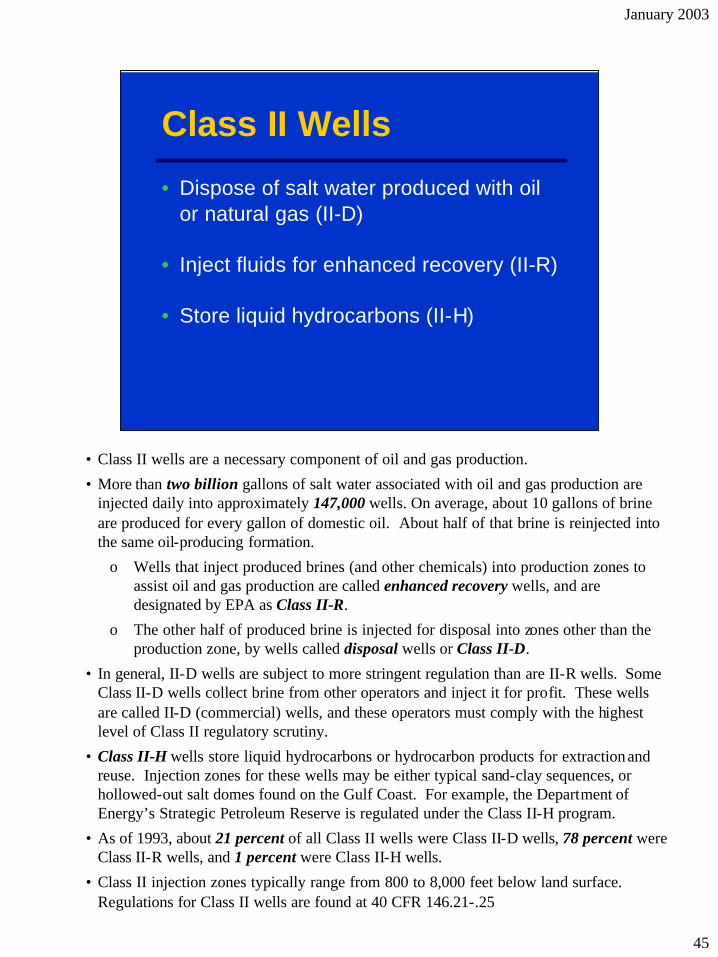
Class II Wells
• Dispose of salt water produced with oil or natural gas (II-D)
• Inject fluids for enhanced recovery (II-R)
• Store liquid hydrocarbons (II-H)
• Class II wells are a necessary component of oil and gas production.
• More than two billion gallons of salt water associated with oil and gas production are injected daily into approximately 147,000 wells. On average, about 10 gallons of brine are produced for every gallon of domestic oil. About half of that brine is reinjected into the same oil-producing formation.
o Wells that inject produced brines (and other chemicals) into production zones to assist oil and gas production are called enhanced recovery wells, and are designated by EPA as Class II-R.
o The other half of produced brine is injected for disposal into zones other than the production zone, by wells called disposal wells or Class II-D.
• In general, II-D wells are subject to more stringent regulation than are II-R wells. Some Class II-D wells collect brine from other operators and inject it for profit. These wells are called II-D (commercial) wells, and these operators must comply with the highest level of Class II regulatory scrutiny.
• Class II-H wells store liquid hydrocarbons or hydrocarbon products for extractionand reuse. Injection zones for these wells may be either typical sand-clay sequences, or hollowed-out salt domes found on the Gulf Coast. For example, the Department of Energy’s Strategic Petroleum Reserve is regulated under the Class II-H program.
• As of 1993, about 21 percent of all Class II wells were Class II-D wells, 78 percent were Class II-R wells, and 1 percent were Class II-H wells.
• Class II injection zones typically range from 800 to 8,000 feet below land surface. Regulations for Class II wells are found at 40 CFR 146.21-.25
45

January 2003
Class II Wells
• May have multi-well area permits
• Existing enhanced recovery wells (i.e., drilled before State program approved) may be authorized by rule for the life of the well
• Must demonstrate mechanical integrity at least every 5 years
• Monthly monitoring of injection pressure, flow rate, and volume
• Brine leaks might increase the salinity of USDWs, but even at low concentrations the water tastes so bad that humans cannot drink enough to be harmed. In the case of large-scale contamination, however, USDWs can be ruined as drinking water sources. Because of the nature of the injectate and the economic incentive for the operator to keep wells in good order, EPA assigns Class II wells a lesser le vel of regulatory attention.
• Class II well operators must conduct and pass an internal MIT once every five years. External MI for Class II wells is determined by evaluating the cementing records once, during permitting or file review.
• Class II well operators will spend up to $400 to prepare a permit application. In some cases, multi-well area permits are allowed, meaning multiple wells (sometimes up to several hundred wells at a time) are authorized under one permit. This effectively reduces the cost of the permit per well. The permit process takes two to four months, and Class II permits are valid for the life of the well. Permits are reviewed for compliance every five years.
• Enhanced-recovery wells drilled before 1982 may be authorized by rule, or grandfathered. Wells that are authorized by rule make up about 50 percent of the current Class II inventory.
• The radius of the area of review for Class II wells is almost always 1/4 mile.
• Class II well owners and operators must report monitoring data once a year.
46
January 2003
Class II Well Construction WELLHEAD
Injection pressure gauge
Injected fluid
Annular access
Base of protected water
Drilling mud
Bottom of surface casing
Cement
Tubing Packing Perforations Bottom of casing
Annular space
Annulus pressure gauge
Valves
Confining Zone
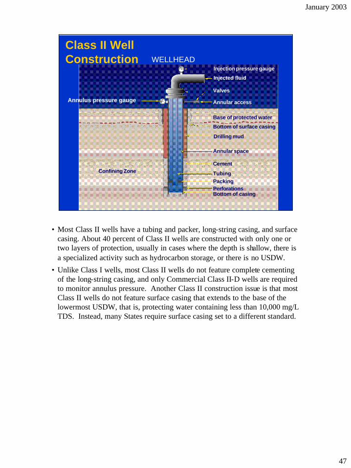
• Most Class II wells have a tubing and packer, long-string casing, and surface casing. About 40 percent of Class II wells are constructed with only one or two layers of protection, usually in cases where the depth is shallow, there is a specialized activity such as hydrocarbon storage, or there is no USDW.
• Unlike Class I wells, most Class II wells do not feature complete cementing of the long-string casing, and only Commercial Class II-D wells are required to monitor annulus pressure. Another Class II construction issue is that most Class II wells do not feature surface casing that extends to the base of the lowermost USDW, that is, protecting water containing less than 10,000 mg/L TDS. Instead, many States require surface casing set to a different standard.
47

January 2003
Class III wells • Used for solution mining minerals, such as salt,
sulphur, uranium and copper
• Inject chemical solutions, super-hot steam, or water into mineral formations
• Hot injectate dissolves and mixes with minerals underground; mineral-saturated solution pumped to surface for mineral extraction
• Injected fluids are frequently reused after some treatment
• Approximately 17,000 Class III wells
• Applicable Federal regulations for Class III wells can be found at 40 CFR 146.31-.35.
• Class III wells inject chemical solutions, super-hot steam, or water to recover minerals from subsurface injection zones. Generally, the fluid is treated and reinjected into the same formation. An injection-mining project may use hundreds of wells, and most wells are temporary. EPA’s 1999 inventory of UIC wells indicated that 16,741 Class III wells were in existence in the U.S. More than 50 percent of the salt and 80 percent of the uranium production in the U.S. uses Class III injection wells.
• Class III injection zones typically range from 80 to 3,000 feet below surface, and projects are frequently located in temporarily exempted USDWs. In these cases, restoration standards for the USDW after mining are issued as part of the permit. The operator posts an equivalent bond and at the conclusion of mining the operator is required to return the USDW to approximately its pre-mining condition. In addition, operators of Class III mining projects are usually required to monitor the boundaries of the mined area for fluid excursions. For wells completed in USDWs, semi-monthly monitoring of the injection zone and overlying USDWs generally is required.
48

January 2003
Class III Well Construction In Situ Leaching WellSolution Mining Well
Cement
WellheadWellhead
Centralizer
Casing
Drill hole Cement basket
Plug (drilled out after Cementing)
Cap
Slotted screen or pipe
Mineralized zone
Cement
Cement
Surface Casing
Tubing-casing annulus
Top of salt
Production Casing
Tubing
Salt cavern
• There are two major types of Class III wells. Solution mining wells are used primarily to extract salt and sulfur from underground formations. Well operators inject water to extract salt and super-heated steam to melt and extract sulfur.
• In-situ leaching wells are commonly used to extract uranium, and in some instances gold and copper, from subsurface layers. A non-toxic chemical solution is circulated through the formation, which dissolves or “leaches” mineral particles from the sand grains in the ore body.
49

January 2003
Class III Wells
• May have multi-well area permits
• Wells drilled prior to program approval may be rule-authorized until permitted
• Salt solution wells must demonstrate MI at least every 5 years
• Well owners and operators report well data annually
• Class III mining fluids can be toxic, but because the effects from many Class III projects are temporary and because the operator has a strong economic incentive to maintain his wells, the regulations are not as stringent as those for Class I wells. Class III well owners and operators are required to conduct MIT once every five years for salt solution mining wells.
• The construction of Class III wells varies based on the type of mineral to be extracted, the local geology and other factors. One or two layers of protection are required and in some cases, PVC plastic lining is used.
• A Class III owner or operator will spend approximately $50-1500 per permit application. Similar to Class II wells, in some cases, a multi-well area permit may be granted. The permit review process for Class III wells lasts from 6-12 months. Class III permits are valid for the life of the well however, permits are reviewed for compliance every 10 years. Wells drilled before 1982 are authorized by rule.
• The area of review radius for Class III wells ranges from 1/4 to 2-1/2 miles. Class III well owners and operators must report well data to the UIC program once a year.
50

January 2003
Class IV Wells • Used to dispose of hazardous or
radioactive waste into or above a formation which contains a USDW within 1/4 mile of the well
• Prohibited – One exception: wells that reinject into same
formation treated ground water pursuant to approved CERCLA or RCRA clean-ups
– Voluntary site clean-ups not subject to exception
• Class IV wells inject hazardous or industrial waste illegally into (or above) USDWs. This class of wells is prohibited, and the classification serves only as a basis for enforcement. Regulatory attention by EPA to a Class IV well is urgent and immediate. Hazardous waste injected into USDWs provides the most severe potential for endangerment of human health. Discovery of a Class IV well results in immediate enforcement proceedings. These wells are occasionally encountered, often as a result of complaints filed by anonymous workers or nearby citizens. They may also be discovered during site inspections, or during investigation of property near a contaminated public water supply.
• There is one exception to the prohibition of injecting hazardous wastes into USDWs. Some aquifer remediation projects use “pump and treat” systems that withdraw contaminated water from an aquifer, treat it to remove the hazardous constituents, and reinject it. In some cases, however, the treated water is still a hazardous waste as the treatment may not have removed the hazardous constituents to acceptable levels. Pump and treat systems often must operate for long periods of time to successfully reduce the constituents.
• EPA has decided that this type of beneficial injection is not prohibited if the injection takes place at an EPA-approved RCRA or Superfund remediation site and the water is returned to the same formation from which it was withdrawn.
• Class IV wells at a site employing voluntary clean-up actions, or that fall under a regulatory program other than RCRA or CERCLA, are not eligible for the exemption and still are prohibited.
51

January 2003
Possible Class IV Well
• Class IV wells, while illegal, are still being found today. These wells may be at large industrial facilities, or located at small businesses. The 1999 EPA UIC inventory listed 22 Class IV wells. Wells in or near areas where hazardous or radioactive wastes are stored, treated or otherwise managed are prime candidates for becoming Class IV wells due to substances being poured into them, or leaks and spills draining to them. Floor drains in buildings or drains in or near loading docks, for example, are highly likely to receive hazardous waste managed in the area if the facility does not take great care in material handling.
• The hazardous or radioactive wastes disposed into a Class IV well may have been placed in the well intentionally or unintentionally through a leak or spill. “Intent to inject,” while generally factored into a penalty amount, is not used as a basis to determine whether “injection” into the well has occurred.
• When an EPA employee finds a Class IV well, it is very important to collect detailed information about the well and its conditions, as well as injection and waste management practices that can be documented. As mentioned earlier in the course, the UIC Inspector Training for EPA UIC employees provides important information about how to appropriately inspect and document this type of well.
• One Class IV well discovered in Ohio in the late 1990s was located at a small furniture refinishing shop. An individual operated this business for extra income, and dipped furniture into a tank of caustic stripper to remove old finishes from the wood. Periodically, the owner would neutralize the caustic when it became spent, and drain it to a floor drain. The floor drain led to a pipe under the building, which eventually led to a dry well. Upon sampling, the material in the well exceeded hazardous waste regulatory levels for lead. Fortunately, the caustic was neutralized prior to disposal, or the impact of disposal likely would have been much greater. This site was very near private drinking water wells, and the dry well was located just above a significant USDW.
52

January 2003
Class V Wells
• Class V: the definitions of Classes I, II, III, or IV
• Most are shallow and low-tech
• Most inject into or above USDWs
• Operators must submit inventory information
• Must not endanger USDWs
All injection wells that do not meet
• Class V is a catch-all category—Class V wells use injection practices that are not included in Class I, II, III, or IV. Some Class V wells are sophisticated injection systems used by industry, but most are “low-tech.” Generally, they are shallow and depend on gravity to drain or “inject” liquid waste into the ground above or into USDWs. While some Class V wells inject below the lowermost USDW, the material injected is not an industrial or municipal waste, or these would be Class I wells.
• The simple construction of the majority of Class V wells provides little or no protection against possible ground water contamination, so it is important to control the injectate.
• Some Class V wells are found to inject non-hazardous waste streams that contain hazardous components on an intermittent basis (such as a car repair facility that occasionally disposes of excess oil and chemicals). EPA or States may decide to close the well immediately, or to allow the operator to permanently remove the source of the hazardous constituents and continue to operate the well as Class V.
• Under the existing Federal regulations, most Class V injection wells are authorized by rule (40 CFR Part 144). The well owner or operator must submit basic inventory information to EPA or the State primacy agency and ensure that the Class V injection well is constructed, operated, and closed in a manner that protects USDWs. EPA or a State primacy agency may ask for additional information or require a permit in order to ensure that USDWs are adequately protected. Further, many State UIC primacy programs have additional prohibitions or permitting requirements for certain types of Class V injection wells.
• EPA promulgated a final rule on December 7, 1999 (http://www.epa.gov/safewater/c5fedreg.html), that placed a nationwide ban on new Class V motor vehicle waste disposal wells as of April 2000. It also requires phasing out existing large capacity cesspools by April 2005. The requirements for existing motor vehicle waste disposal wells are being linked with critical ground water areas, including some areas assessed through State source assessment and protection programs. All existing motor vehicle waste disposal wells in these critical ground water areas will have to be closed or permitted.
53

January 2003
Class V Wells
Source:
Industrial Facility
Commercial Drainage
Areas
Service Station Repair
Bay
Residential Areas
Agricultural Drainage
Well
Septic Tank
Treatment Plant
Mineral & Fossil Fuel Recovery
Improved Sinkhole
Fractured Bedrock
Industrial Process Water and
Waste Disposal
Well
Sandstone
Limestone
Heat Pump Air Conditioning
Return Flow System
Agricultural Areas
Ohio EPA
• EPA documented 686,000 Class V wells nationwide (The Class V UIC Study, EPA 816-R-99-014a, September 1999). The most recent estimate in 2002 is 650,000 wells, based on state estimates and modeling of storm water wells and large capacity septic systems. Class V wells are located in every State except American Samoa, especially in unsewered areas where the population is likely to depend on ground water for its drinking water source. 40 CFR 146.5(e) identifies some types of Class V wells. Because of the very large number of Class V wells, many of which are owned and operated by small businesses, the benefits of possible regulatory schemes must be weighed carefully against cost impacts to industry, farmers, municipalities, and the public.
• Some wells are used for beneficial purposes (e.g., salt-water barrier wells prevent salt water from intruding into fresh water supplies), but the effects of most types of wells are not well documented. EPA is concerned that the shallow depth and poor construction of some Class V wells may allow continuous or intermittent flow of contaminants into USDWs. The locations and site-specific operating characteristics of most wells are not documented either. The challenge to EPA is to find, identify, assess the risk of, and effectively regulate Class V wells.
• Definitions for each well type are available on the EPA Web site (http://www.epa.gov/safewater/uic/ cl5study.html#fact) and in the CFR.
• Class V wells identified by EPA include: agricultural drainage wells, storm water drainage wells, special drainage wells, geothernal electric power return flow wells, geothermal direct heat return flow wells, heat pump/air conditioning return flow wells, solution mining wells, spent brine return flow wells, in-situ fossil fuel recovery wells, mine backfill wells, sewage treatment effluent wells, large-capacity septic systems, aquaculture wells, aquifer recharge and recovery wells, salt water intrusion barrier wells, subsidence control wells, experimental wells, aquifer remediation wells, la rge-capacity cesspools, industrial wells, motor vehicle waste disposal wells, car washes, food processing disposal wells, laundromats without dry cleaning facilities, and non-contact cooling water. Private, individual family septic systems are exempt from the UIC program.
54

January 2003
Specific ExclusionsSpecific Exclusions •• Injection wells on drilling platforms or Injection wells on drilling platforms or
elsewhere beyond State’s territorial waterselsewhere beyond State’s territorial waters •• Individual or singleIndividual or single--family residential waste family residential waste
disposal systems (cesspools or septic disposal systems (cesspools or septic systems)systems)
•• NonNon--residential cesspools or septic systems if residential cesspools or septic systems if receive only sanitary waste and serve fewer receive only sanitary waste and serve fewer than 20 people per daythan 20 people per day
• Some types of wells are excluded from regulation under the UIC program. The specific wells are listed in 40 CFR 144.1(g)(2).
• Injection wells that are part of a drilling platform or otherwise are located beyond a State’s territorial waters cannot be regulated by the UIC program.
• The regulations specifically differentiate between cesspools and septic systems that serve multi- family units versus individual or single-family systems. Individual or single-family systems are exempt from the UIC regulations as long as they are truly individual or single family systems. For instance, if someone is running a business out of their basement or garage and industrial wastes are disposed into the single-family septic system, that system has now become an industrial waste disposal well.
• Additionally, non-residential cesspools or septic systems are exempt from the UIC program regulations if only sanitary waste is disposed into the system, and fewer than 20 people per day can be served by the system. For instance, the typical school would have more than 20 people per day. If this typical school were rurally located and sanitary waste was disposed through a septic system, the school is operating a Class V well. Conversely, if a building is used as an office complex, has no publicly accessible restroom facilities, and maximum tenant occupancy is 15, this building’s septic system would not be regulated by the UIC program.
55

January 2003
Specific ExclusionsSpecific Exclusions
•• Wells used for injection of gas Wells used for injection of gas hydrocarbons for storagehydrocarbons for storage
•• Dug holes not used for subsurface fluid Dug holes not used for subsurface fluid emplacementemplacement
• If an injection well is used for injection of hydrocarbons that are of pipeline quality and are gases at standard temperature and pressure, and the injection of these gases is for storage purposes, the wells are not subject to UIC regulation. If the wells are used for storage of liquid hydrocarbons, however, they are regulated by the UIC program.
• Last, any dug hole that is not used for emplacement of fluids underground is exempt from the program. So, don’t think you can tell your boss you need to go do an eighteen hole shallow UIC well inspection at your local golf course!!
• Show video: Shallow Disposal Systems Are Everyone’s Business (EPA Publication # 908-V-98-001).
56

January 2003
Objective 4
• Explain some of the challenges faced by today’s UIC program – Class I: – Class I and II: – Class V: -part strategy – UIC streamlining and outreach – Capacity building – 40 CFR Part 147 update
municipal disposal wells hydraulic fracturing
EPA’s two
• Injection wells are a fundamental component of American industry, and some shallow wells are commonly used among our farms and residential communities. Since the advent of the UIC era, starting with the enactment of SDWA in 1974, EPA has been able to effectively incorporate new injection technologies into the program, and respond to challenges posed by innovative uses, State needs and resources, and the courts.
57

January 2003
Class I: Municipal Disposal Wells • Class I municipal wells in Florida inject
large volumes of treated POTW effluent
• Monitoring revealed migration of injected fluids into the lowermost USDW at some locations, in violation of UIC requirements
• LEAF petitioned EPA to withdraw Florida’s UIC program
• EPA is considering Florida-specific rule to address problem
• Environmental officials in the State of Florida were faced with a dilemma concerning municipal, secondary-treated effluent. Massive population increases had continued to increase the amount of municipal effluent available for discharge. Wholesale surface discharge seemed out of the question (especially in coastal and beach communities), due to its effect on recreational waters and the potential for treated effluent to enter shallow USDWs used for drinking water, through sinkholes and fractures in the native limestone.
• Florida turned to injection technology, and allowed the construc tion of Class I municipal disposal wells (i.e., below USDWs) to inject the treated waste water. Florida officials were faced with the same possibility of contaminating USDWs because the same conditions (e.g., holes, fractures, and other irregularities) existed in the injection and confining zones. In FY 1997, EPA reported that about 120 Class I municipal wells were active, injecting approximately 20 percent of Florida’s municipal waste waters.
• As feared, some relatively minor effects of sewage injection were observed in a few USDWs. The Legal Environmental Assistance Foundation (LEAF) challenged EPA in court concerning the validity of the Class I disposal practice. In several court decisions since 1990, EPA has been required to re-examine the use of injection wells for this purpose.
• EPA is considering a Florida-specific rule that would require municipalities to treat the effluent so that it does not violate drinking water standards or demonstrate that no fluids that violate drinking water standards will enter a USDW.
58

January 2003
Hydraulic Fracturing: Class II • 11th Circuit Court of Appeals ruled that
hydraulic fracturing of coal beds to produce methane constitutes underground injection, contrary to EPA’s interpretation of SDWA
• EPA required Alabama to regulate hydraulic fracturing or withdraw UIC program approval
• EPA is studying impacts of hydraulic fracturing on USDWs
• LEAF brought suit against EPA in Alabama concerning fracture-stimulation of a particular type of gas well. These wells tap into pockets of natural gas contained in subsurface coal beds. These coal beds are relatively shallow (150 to 2,000 feet below land surface), and production zones occur within USDWs.
• EPA argued that the agency has no jurisdiction over production wells and practices, and that there have been no documented cases of USDW contamination attributed to this practice. Nevertheless, the Court of Appeals found that injection into a well, however temporary, meets the conditions of SDWA, and ordered EPA to assist the Alabama UIC agency in developing a program to regulate the practice (LEAF v. EPA, 118 F. 3d 1467, August 7, 1997).
o In December 1999, EPA approved this revision to the State’s UIC program.
• Because identical practices are used in about 15,000 other coalbed gas wells in 13 other States, EPA is conducting a study of possible impacts hydraulic fracturing may have on USDWs. The study focuses on hydraulic fracturing used specifically for enhancing coalbed methane production. EPA is gathering information on the hydraulic fracturing process and has requested comment from the public on contamination due to hydraulic fracturing processes (comments were due to EPA by August 29, 2001).
• In this initial effort, EPA will not incorporate new, scientific fact- finding, but will use existing sources of information, and consolidate permit data in a summary report as the basis for the study. EPA will decide if additiona l research is required based on the findings of this study.
59

January 2003
Hydraulic Fracturing: Class I • New technologies allow injection of solid
wastes, but involve continuous hydro-
fracturing
• Currently used on the Alaskan north
slope and offshore, this technology offers
disposal option for contaminated soil
• As discussed earlier, one of the critical pathways of USDW contamination involves excessive injection pressure, which can hydraulically fracture the confining zone and allow injected waste to escape. EPA prohibits Class I operators from fracturing the injection and confining zones (40 CFR 146.13).
• Another current issue is a new injection practice, one with tremendous potential for environmental good, which utilizes hydraulic fracturing as part of the injection technique.
o Several industry tests in the continental U.S. and six operating wells on the North Slope of Alaska have shown that injection wells can accept solid wastes in large volumes.
o The injectate is a slurry made by grinding contaminated solids and liquids together to form a mixture with the approximate consistency of sloppy toothpaste.
o The slurry is injected at high pressures (up to 7,000 psi), and emplacement of the waste requires continually fracturing the injection zone. These wells inject both Class I non-hazardous industrial and Class II oil-production wastes. These injection wells have injected millions of cubic yards of contaminated solids (the equivalent of several landfills) in a protected wetland where landfills are not allowed.
• EPA has permitted these wells using an exemption from the fracturing prohibition, and ensuring that restrictions on well depth and injection rate prevent migration of fractures into USDWs. Many other operators and industries, however, require a secure disposal method for contaminated solids where landfill availability or capacity prevents surface disposal. EPA’s task is to evaluate the overall safety of this process, and define an effective program to regulate its use.
60

January 2003
Class V: EPA’s Two-Part Strategy • Sierra Club consent decree
– 1999 final rule addresses high risk wells (as determined by the administrator) in source water protection areas
– Class V study addresses all other Class V wells to determine the risks they pose and need for additional regulations
• Rule development for Class V injection wells has required a lengthy effort from EPA, due to the tremendous variety of well types and interested and affected parties. After two different regulatory approaches were considered by EPA, the Agency was sued by the Sierra Club. EPA and the Sierra Club entered into a modified consent decree on January 28, 1997 (D.D.C. No. 93-2644). In accordance with this decree, EPA pursued a two-step strategy for Class V wells.
o First, EPA promulgated a final rule on December 7, 1999 (http://www. epa.gov/safewater/c5fedreg.html), as described earlier in slide #54.
o The second step was to conduct a study of Class V wells that are not covered in the rulemaking. Through the study, EPA identified 22 types of Class V injection wells. The study was completed in September 1999 (http://www.epa.gov/safewater/classv.html#general).
• Based on the results of the study, EPA proposed a determination on May 7, 2001 (66 FR 22971) that addresses all the Class V well types not addressed in the 1999 final rule. EPA proposed that existing Federal regulations for Class V wells are adequate to protect drinking water supplies and that additional Federal regulations are not needed at this time.
61

January 2003
Class V Management Plan
• Implement existing Class V regulations • Implement new regulations • Educate well operators • Explore non-regulatory approaches • Prepare for future actions
• EPA’s management plan for Class V injection wells includes the following major components:
o Implement existing Class V regulations. EPA and State UIC programs will continue to implement existing regulations by identifying Class V facilities; effectively and appropriately us ing existing regulatory authorities such as permitting, enforcement and closure; providing increased technical assistance to bring endangering wells into compliance; and developing tools to ensure that well owners/operators remain in compliance.
o Implement new regulations. EPA and States will undertake an intense effort to implement the Class V rule for motor vehicle was disposal wells and large capacity cesspools.
o Educate well operators. Ongoing outreach efforts by States and EPA will continue to educate operators about best management practices and their State and Federal regulatory obligations.
o Explore nonregulatory approaches. EPA will work closely with target industries to establish voluntary standards and practices to protect public health.
o Prepare for future actions. EPA will continue to work with States, industries and environmental organizations to collect and evalua te data on Class V wells and their risks.
62

January 2003
UIC Streamlining and Outreach • UIC streamlining: effort to reduce
requirements on States to report inventory, permitting, compliance, and enforcement
data on 7520 forms
• Outreach: videos, brochures, other tools used to educate communities and individuals
• Reporting was discussed in the section on UIC program structure. The 7520 reporting forms are the mechanism by which EPA compiles inventory, permitting, compliance and enforcement information about the national UIC program. EPA Regional and Headquarters staff use the information to make decisions regarding program priorities, UIC regulations, compliance and enforcement actions, and funding for State and Regional UIC programs.
• As part of an ongoing effort to identify ways to reduce paperwork burden, EPA is undertaking an effort to streamline the UIC program reporting requirements. The Agency is considering program changes suggested by stakeholders in the UIC Forms Revision Workgroup, which includes Federal and State regulators. Once EPA and the workgroup reach consensus on the most efficient way to report program data, EPA will redesign the 7520 reporting forms.
• Outreach and education are critical to accomplishing the UIC mission. Injection wells in general are often misunderstood and frightening to the public. Further, the large number of Class V wells make it extremely difficult to regulate all of the wells and even more difficult to enforce regulations. Therefore, outreach and education informing the public in general, and Class V owners/operators in particular, about risks and appropriate management techniques is essential. EPA has produced a video on shallow injection wells, and has a number of brochures and pamphlets to help address this program priority. Information is also available on OGWDW’s Web site (http://www.epa.gov/safewater).
63

January 2003
Capacity Building
• GWPC-led project to identify key
activities for effective State UIC
programs and estimate total funding
shortfall
• Recent focus on Classes II and V
• The Ground Water Protection Council (GWPC) and EPA are working to estimate national resource needs for developing and maintaining effective State UIC programs. They convened a work group of Agency and State UIC representatives in the fall of 1997 to identify activities that effective Class V UIC programs should perform. EPA then developed a five-year spreadsheet model designed to estimate State funding required to perform the work group's recommended activities. Finally, GWPC and EPA estimated the national funding shortfall based on the model results and prepared an outreach report to document the modeling effort.
• In a second phase of the project, GWPC and EPA performed onsite evaluations of several State Class V UIC programs to determine to what extent they perform the activities identified by the work group with available resources, and to identify State priorities for additional funding.
• A similar effort regarding Class II wells also has been completed, and a report of findings prepared as well. No significant additional funding needs were identified for this portion of the program.
64

January 2003
40 CFR Part 147 Update • Update State UIC program descriptions,
and statutes and regulations incorporated by reference
• Last updated in 1991
• Can require significant Regional and State resources
• The regulations at 40 CFR Part 147 codify the program descriptio ns and incorporate by reference the rules and regulations of primacy States. This allows EPA to take direct enforcement action in primacy States. The regulations were first promulgated in 1983. The rules were updated in 1984, 1988, 1993 and 1999. The last update to 40 CFR Part 147 was in 1991.
• Primacy States are required to submit to EPA Regional Offices all revisions of laws and regulations that support delegation or otherwise affect the State UIC program. The Regional Offices and EPA Headquarters make determinations, per UIC Guidance 34, whether the revisions are considered “substantial” for the purpose of evaluation and approval. If the revisions are considered substantial, they are published in the Federal Register upon approval. Thus, there is a record of the action for later codification in Part 147.
o However, it is very likely that either some of the States have failed to submit program revisions, or the approved revisions were not published in the Federal Register.
o In addition, because the great majority of program revisions have been classified as “non-substantial,” EPA expects that there are few records and that extensive new materials must be added to Part 147.
• Changes to relevant State statutes and regulations incorporated by reference are to be published in the Federal Register.
• The update also may require an update of State program descriptions. Depending on the number of changes, this can be very time and resource consuming for both the Regional Offices and the State programs.
65