introduction - synthmanuals.com two programmable control wheels, left wheel has spring-return and...
TRANSCRIPT

INTRODUCTION
The SL-2001 is a unique MIDI instrument which combines powerful master keyboardfunctions with versatile MIDI processing features Its operating system has been care-fully designed for fast and efficient musical control of any MIDI system, from small homestudios to professional stage setups
The SL-2001 is like any musical instrument, the more time invested, the greater therewards Once the basic principles of operation aie mastered, the many powerful func-tions are easily accessible It is not necessary to read and understand every detail of theSL-2001 operation guide, but please take the time to scan all of the sections to gainawareness of the unit's full potentialSections 1 through 4 contain essential information and should be read carefullySections 5 through 8 aie reference sections which detail all of the powerful functionsavailable, and may be studied as required.

1 QUICK REFERENCEFor basic operation please follow the guidelines below. The SL-2001 includes eight demonstration presets which may beused after the instrument is installed into your MIDI system.
1. Connect voltage adapter into a power outlet (make sure voltage specification on power adapter matches your line volt-age). Connect adapter cable to SL-2001 power jack.
2. Connect MIDI cables before switching on any MIDI devices. To use the demonstration presets, connect a sound moduleto each of the four MIDI outputs A-D. Each sound module should be set to receive on MIDI channel 1.
4. Apply power to all MIDI devices in the system.
5. Switch on the power to the SL-2001.
To change SL-2001 presets, make sure that the unit is in Perform Mode (red light on EDIT switch is off). To change the pre-set, press any of the eight PRESET switches. To change to a different bank, press the left or right arrow switches( < > ) until the desired bank number is displayed before pressing one of the eight PRESET switches. Presets are arrangedin eight banks of eight, for a total of 64 presets (11 through 88). An optional memory card is available which holds 64 addi-tional presets.
Local controllers (front panel sliders, Star and Alpha switches, footswitches A through C, and control voltage inputs 1 and 2)will issue MIDI control change commands depending on the selected preset.MIDI devices may be switched on and off using the eight ZONE switches.
To edit a preset, enter Edit Mode by pressing the EDIT switch. Press the appropriate FUNCTION switch to access the desiredfunction (press several times if necessary until the desired screen appears on the text display). If a star (*) appears in the dis-play, an alternate screen may be accessed by pressing the Star switch. Adjust the parameter with the appropriate control slid-er. To change parameters for a specific zone, first select the appropriate zone by using the left and right arrow switches. Theselected zone is indicated by the zone digit(s) following the preset number.
IMPORTANT: Before the SL-2001 can be effectively programmed for your MIDI system, all MIDI devices must be properly"installed" into the SL-2001 operating system. Refer to the DEVICES function in section 4 for information on this procedure.
DEMONSTRATION PRESETS
The SL-2001 comes from the factory with 8 demonstration presets in locations 11 through 18. The demonstration presets areintended for use with four MIDI sound modules. Each sound module should be set for MIDI channel 1, and each shouldeach be on a separate MIDI output. The demonstration presets illustrate several of the most useful SL-2001 functions, andare summarized below. When the demonstration presets are selected with the PRESET switches, the sound modules shouldchange programs automatically. The actual program number on each sound module may not match the number of the pre-set selected on the SL-2001. These program numbers may be easily changed; see the operation guide sections on Edit Modeand the Program function.
DEMONSTRATION PRESET 11: All four sound modules are active and receiving note information from the keyboard. TheZONE switches may be used to turn off selected sound modules to hear different combinations of the modules. The fourcontrol sliders on the front panel are used to adjust the volume level for each sound module (refer to the CONTROLS func-tion in section 8 for information on programming sliders and control pedals).
DEMONSTRATION PRESET 12: All four sound modules are active, but the keyboard is divided into four zones, with a dif-ferent sound module active in each zone (refer to the ZONE function in section 8 for more information).
DEMONSTRATION PRESET 13: All four sound modules are active, but each key that is played on the keyboard is assignedto a different sound module, (refer to the NOTES function in section 8 for more information).

DEMONSTRATION PRESET 14: All four sound modules are active, but MIDI information for modules 2, 3, and 4 is delayed,with module 2 set for the shortest delay and module 4 set for the longest. The two wheel controllers may be used to changepitch or add modulation; this MIDI data will be delayed along with the note information, creating a unique effect (refer to theDELAY function in section 8 for more information).
DEMONSTRATION PRESET 15: This preset demonstrates the velocity switch function. For notes played softly on the key-board, only the first sound module will play. As the keys are struck more forcefully, module 2, module 3, and finally mod-ule 4 will sound (refer to the VELOCITY function in section 8 for more information).
DEMONSTRATION PRESET l6: This preset uses only MIDI sound module numbers one and two, and demonstrates what isknown as a velocity cross-fade. For notes played softly on the keyboard, only sound module number 1 should play at max-imum volume. As the notes are struck more forcefully, sound module 1 will become softer, and sound module 2 will becomelouder (refer to the VELOCITY function in section 8 for more information).
DEMONSTRATION PRESET 17: This preset demonstrates MIDI delay combined with multiple key transpose settings to pro-duce an arpeggio for every note that is played on the keyboard. Only sound module #1 is used in this preset. For best results,this module should be capable of playing eight or more notes simultaneously (refer to the TRANSPOSE function in section 8for more information).
DEMONSTRATION PRESET 18: The SL-2001 is capable of generating long MIDI delays with independent time settings foreach sound module. This preset has zero delay for the first sound module, and delays of 2.5, 5, and 7.5 seconds for the sec-ond, third, and fourth modules respectively.
SL-2001 SPECIFICATIONS
* Full-size 88-key weighted action with velocity sensitivity and aftertouch.
* 48-character LCD display with backlight* Sixty-four presets stored internally; optional memory card for 64 additional presets.
* Four MIDI inputs may be used for additional keyboards, MIDI accessories, sequencers, etc. Theinputs may be merged in any combination into any of the outputs. All SL-2001 masterkeyboard functions are available for the external keyboards.
* Four fully independent MIDI outputs, for a total of sixty-four MIDI output channels.
* Two programmable control wheels, left wheel has spring-return and center detent. Each wheel may beprogrammed to issue up to eight different messages per preset.
* Four programmable control sliders. Each slider can be programmed to issued as many as eight differentmessages per preset.
* Three programmable switch inputs. Each switch may be programmed to issue any MIDI switch message,or used to enable/disable any of the keyboard zones.
* Preset increment and decrement inputs.
* Two programmable voltage inputs. Each input may be programmed to issue up to eight MIDI controlmessages per preset.
* Eight keyboard zones may be defined over any region of the local or external keyboards. Each zone is fullyprogrammable for optimum control of the destination MIDI synthesizer.
* Utility Functions MIDI Activity Memory. Used Clear Preset/All(section 5) Clear Memory Card Save to/from Card Save to/from MIDI

* Global functions:(section 6)
* Preset functions(section 7)
* Zone functions:(section 8)
Device List
Preset NameSwitch Modes
Zone DefineDelayVelocity CurveNote FilterKey HoldLocal Controllers
Preset Chain
Slider Names
Key RangeProgram ChangeVelocity ScaleVolumeTransposeMIDI Controls
Preset Change Enable
Aux Program Change
Zone ControlVelocity SwitchVelocity OffsetVolume ControlChordMIDI Switches
* Accessories: Sustain footswitch included. Additional footswitches, memory card, and voltage pedal optional.* Power Requirements: 9VDC at 500mA (power adapter supplied).
2 BASIC INFORMATIONThe SL-2001 MIDI Master Keyboard serves as the central controller for any group of MIDI instruments and accessories. Withfour MIDI inputs and outputs and powerful MIDI processing functions, the SL-2001 eliminates the need for outboard MIDIswitchers or other devices. Full programmability means that your time is spent making music, not reconfiguring the equip-ment.
The SL-2001 will command at least eight sound modules (or keyboard synthesizers) simultaneously and at least eight auxil-iary MIDI devices (audio effects units, mixers, lighting controllers, etc). More than thirty-two MIDI devices may be connect-ed and selectively accessed under preset control. The four MIDI outputs are completely independent, which means thatsixty-four MIDI channels are available.
BACK PANEL CONNECTIONS
MIDI INPUTS: Four MIDI inputs are provided to support several additional performance devices at once (other keyboards,guitar controllers, sequencers, etc). The MIDI data from any of these external sources may be processed and zoned in thesame way as the master keyboard, or it may be passed straight through to any of the outputs.
MIDI OUTPUTS: The four MIDI outputs will support a large number of MIDI devices as each output may contain informa-tion on several MIDI channels simultaneously. A total of 64 slave devices are addressable under preset control.
SWITCH INPUTS: Three stereo phone jacks are provided for control footswitches. A double footswitch is included with theSL-2001, and will normally be connected to the SUSTAIN / A input. The SUSTAIN footswitch on the right will function as aconventional piano sustain pedal, while the A footswitch on the left may he programmed for a wide range of MIDI functions.Its most commonly used function is to activate or disable one or more zones during a performance. An additional doublefootswitch may be purchased and may be used in either the B/C input or the (preset) increment/decrement input. InputsB/C may be programmed to control zones, issue MIDI control changes, or other functions. For live performance, many play-ers will want to use three double footswitches simultaneously, in order to effect quick sound changes while playing the key-board.
Although stereo jacks are used for the switch inputs, a standard normally-open footswitch with a mono phone plug may alsobe used. It will function as either SUSTAIN, switch B , or program increment. If desired, the switch inputs may be used asvoltage inputs. The voltage range is from 0 to 5 volts DC, with 0 volts corresponding to the footswitch being pressed.CONTROL VOLTAGE INPUTS: Two inputs are provided for external analog controllers. An optional control pedal is avail-

able from your dealer, or any DC control voltage source may be used. The input voltage range is 0 to 5 volts DC, which cor-responds to a MIDI control range of 0 to 7F hex. The control pedal is most commonly used to control volume.
MEMORY CARD
The SL-2001 is equipped with a connector for a plug-in memory card. The optional memory card is used to make back-upcopies of SL-2001 presets as well as giving quick access to an alternate set of presets. Use of a memory card for saving inter-nal presets is strongly recommended. Before performing any Save or Load operation, be sure that the card is firmly insertedinto the connector as far as it will go. The card may only be inserted with the printed side facing up. When not in, use, storethe memory cards in a safe place away from excessive heat or moisture. | :
The memory card contains a battery which should be replaced after five years of use. The plastic clip which holds the bat-tery may be removed by carefully pulling it from the end of the card (to the right of the memory-protect switch). The bat-tery should only be removed when the memory card is inserted in a SL-2001 and power is applied, otherwise the data in thecard will be lost. Contact your dealer for replacement battenes. 1
MIDI SYSTEM CONFIGURATION
The illustration (facing page) shows .a typical medium-sized MIDI system configured around the SL-2001. Most systems willinclude a combination of keyboard synthesizers, sound modules, and effects units. When using keyboards that producesound (as opposed to a MIDI control keyboard), set the instrument to "local off mode. This will disconnect the sound-gen- /erating circuitry from the keyboard. The instrument can now be considered as two devices: a controller keyboard with a /MIDI output, and a sound module with a MIDI input (consult your operation manual for instructions on the "local off" mode). /'As many as four external keyboards may be connected and used as master controllers for the entire system.
The sound modules should be distributed evenly among the four MIDI outputs to avoid congesting any MIDI lines withexcess information. In the example, two sound modules have been cascaded on MIDI output C, and two effects units aresharing MIDI output D. When multiple units are on the same MIDI output, they must have unique MIDI receive channels,so that each can receive independent MIDI data from the SL-2001. The total number of MIDI channels per output must notexceed sixteen. If a sound module can receive all sixteen MIDI channels simultaneously, it cannot share a MIDI output withany other device.
If there are more than four sound modules in your system, the MIDI-THRU jacks on each unit can be used to connect addi-tional sets of units. If more than twelve modules are used, it is a good idea to use a multiple-output MIDI-THRU box on eachSL-2001 output. The SL-2001 can access up to 64 slave devices, without requiring any repatching of MIDI cables:

MIDI CONFIGURATION

INSIDE THE SL-2001
The SL-2001 is very unique among MIDI keyboards. All of its powerful master controller functions are available from its ownkeyboard, or from any external MIDI keyboard. In addition, the SL-2001 also functions as a very versatile MIDI switcher,router, and processor, which eliminates the need for many outboard MIDI devices.
The diagram above depicts the internal structure of the instrument. There are four MIDI inputs and four MIDI outputs. Eightindependent MIDI data processors link the keyboard and MIDI inputs to the MIDI outputs. Each processor can be pro-grammed to receive data only from a specific region of the master keyboard or external keyboards; it is therefore convenientto refer to the processors as ZONE 1 through ZONE 8. MIDI information fromtwo or more zones can be merged (combined) into the same MIDI output. If desired, all eight zones may be merged into
the same output, although the inherent speed limitation of the MIDI format may result in sluggish response.The configura-tion of the zones is programmable for every preset on the SL-2001. In general, each zone will be associated with one MIDIsynthesizer connected to the MIDI outputs. In special cases, several zones will be processing MIDI data which will all bemerged to the same MIDI output and received by a single sound module.
ZONES
The SL-2001 keyboard will send MIDI data to as many as eight instruments simultaneously (the instruments may be physi-cally separate devices, or different MIDI channels of a multi-channel sound module). Each instrument receives MIDI datafrom one of the eight zones. The sophisticated MIDI processing performed by the zone allows very precise control over thesound and response of each instrument. The function of all eight zones is independently programmable in each of the sixty-four SL-2001 presets.
The diagram above illustrates the internal structure of a zone. A MIDI message from a SL-2001 input port is received by allzones connected to that input. If the zone is not active (front panel ZONE switch is off), no further processing occurs. If thezone is not bypassed, an incoming message is checked to see that its channel matches the channel programmed into thezone's Channel Filter. If the channel does not match, the zone ignores the message.

If the channel is matched, the MIDI message continues through the zone. MIDI note messages are processed by many mas-ter control functions, which may modify the note number, velocity, or perform other sophisticated processing. MIDI con-troller messages may be passed unchanged, converted to a different controller message (mapped), or blocked completely.The resulting MIDI message is then assigned a specific MIDI channel, delayed (programmable from zero to ten seconds), androuted to one of the four MIDI outputs.
The zones are able to issue program change and controller initialization values (volume, modulation, etc.) at the instant a SL-2001 preset is selected. These messages will be issued even if the ZONE switch is off. If the zone is activated later with afootswitch, the sound module will already be set for the proper program and controllersettings. Program and controller initialization messages may be enabled or disabled as discussed in section 8.
When the SL-2001 is used as a general-purpose MIDI switcher, a zone may be bypassed to allow all MIDI data to How fromthe zone's input to its output. The messages retain the same channel number as received. This mode is useful for sequencerapplications, where data on all sixteen MIDI channels is passed as a group from a SL-2001 input to a SL-2001 output, (sys-
• tern-exclusive data is passed ONLY through bypassed zones). None of the processing or controller initialization functionsare available when a zone is bypassed.
Regardless of zone mode, all note messages issued to the output are monitored. Whenever a zone is turned off, note-off mes-sages are automatically issued to clear any sustained notes.
DEVICE NAMES
The SL-2001 offers simplified programming and operation by allowing all MIDI devices in the system to be designated by afive-character name. Before any programming begins, these names are entered into the SL-2001. While entering the devicenames, the user also specifies the MIDI port to which the device has been connected (MIDI IN A-D or MIDI OUT A-D) andthe MIDI channel (1 through 16) on which the device is set. For all subsequent programming, devices are specified by nameonly; the port and channel are not required as they are implied by the name. For large MIDI systems in particular, this makesprogramming much more efficient as it relieves the musician of having to remember the port and channel number for eachdevice.
Some synthesizers are multi-timbral, which means that they are able to produce several different sounds simultaneously, suchas strings, organ, and piano sounds. Each of the sounds is controlled by information on a different MIDI channel. Whenused with the SL-2001, a multi-timbral instrument should actually be considered as more than one instrument, and eachshould have a unique name in the SL-2001 device list. For example, if sound module XYZ can produce two sounds inde-pendently, we can install two devices into the SL-2001: XYZ1 and XYZ2.
The SL-2001 master keyboard is represented by the device name "2001"; this name may not be edited or deleted. Be sure toconsult section 4 to install device names before you attempt to program the SL-2001.


OPERATIONThe SL-2001 front panel is designed for fast and efficient programming of all functions. Learning to operate the unit is veryeasy, as the large 48-character LCD text display assists by presenting function and parameter names which are usually self-explanatory. In addition, all MIDI devices connected to the SL-2001 are designated by five-character names, which greatlysimplifies programming of presets.
The Front Panel diagram identifies the various controls and display areas. There are only two operating modes: PerformMode and Edit Mode. The front panel of the SL-2001 is color-coded to indicate the function of each control in Perform (graylabels) or Edit mode (blue labels).
The EDIT switch is used to select between Edit and Perform Modes (the red LED on the switch is lit in Edit mode). Edit modeis used to edit an existing SL-2001 preset or to create a new one. While in Edit mode, the SL-2001 is still active and perform-ing MIDI data processing (although certain functions are inhibited which would interfere wdth the programming procedure).Once the presets have been programmed as desired, the unit should be switched to Perform Mode. The STORE switch isused to record an edited SL-2001 program into a specific preset location, or to copy presets from one location to another. TheStore function can be used while in either Perform Mode or Edit mode.
A special All-Notes-Off function has been provided to clear any notes that become stuck on synthesizers and sound modulesreceiving data from the SL-2001. Pressing the EDIT and STORE switches simultaneously will initiate a sequence of messagesto the MIDI slave devices which should clear the stuck notes. Using the All-Notes-Off function will not change the currentSL-2001 operation mode.
PERFORM MODE
During performance or recording sessions, the SL-2001 will normally remain in Perform Mode. While in Perform Mode, thetext display presents very useful information regarding the current preset.
Preset Name: A 10-character label entered by the user that describes the current preset. Presets may be selected either frominternal memory or the card memory (if present). If the current preset resides in the memory card, the preset name willappear in square brackets [preset name].
Switches: Displays the status of the three general-purpose switches (controlled by the back-panel input jacks). If a switch ison, the switch letter (A, B, or C) will appear. If the switch is off, there will be a dash. Note that these letters indicate the cur-

rent state of the switch, which may not directly correspond to whether the footswitch is pressed. See section 7 for informa-tion on programming the switch modes and initial values.Chain: If the chain function is being used, the selected chain (A through Z) will appear, followed by the current step num-ber. If the selected chain has not been programmed, the step number will not appear.
csl 1 - csl 4: Labels selected.by the user to describe the function of the four control sliders in the preset. There are a total oftwenty-four characters in this line. This area may alternately be used to display any other general information concerning thepreset.
Preset Digits: There are sixty-four presets in the SL-2001 arranged in eight banks of eight presets. The optional memory cardstores an additional sixty-four presets. Throughout this operation guide, the word preset refers to the storage location of theSL-2001. The word program refers to a particular sound setting of an external instrument. To call up a new preset, first usethe left or right arrow switches to select the desired bank (if different from the current hank). The first display digit willchange to the new bank, and the second digit will turn off. Next, use the eight PRESET switches to select the desired preset.The new preset will be loaded and the text display will change to reflect the new preset. If the Conditional Preset Changefunction (Section 6) is enabled, the SL-2001 preset will change only after all keys have been released from the keyboard andthe sustain pedal is released. The new preset number will Hash until these conditions are met. If the Conditional function isoff, any notes sounding on the MIDI sound modules will be turned off automatically before the preset is changed.
The SL-2001 presets are stored in non-volatile memory circuits powered by a lithium battery when the power is switched off.After several years of operation, the battery will need to be replaced. A warning message will appear on the LCD display ifthe battery voltage is too low. Contact your dealer for a replacement battery.The sixty-four memory card programs are stored in eight banks of eight presets. The card program banks are stored con-secutively with the internal banks. If you use the left or right arrow switches to select a bank number that is greater thaneight or less than one, the SL-2001 will enter the card memory area. When one of the eight PRESET switches is pressed, thenew card preset will be active. Card presets are denoted by square brackets around the preset name in the text display.
When receiving MIDI program change commands, the SL-2001 interprets program change numbers 0 through 63 as internalpresets (11 through 88), and program change numbers 64 through 127 as card presets.
The ZONE switches indicate whether each zone is active or disabled. These switches may be pressed at any time to enableor disable a zone. Depending on the configuration of the preset, several zones may be sending MIDI information to the samesound module. To prevent notes from sounding on this module, it will be necessary to turn off all zones associated with themodule. Any notes that are sounding when a zone is deactivated will be automatically turned off.
The two switches below the EDIT and STORE switches are the Star (*) and Alpha (a) switches. In Perform Mode, the func-tion of these switches is fully programmable. They may be used to activate sound modules, send MIDI messages, or otherfunctions.
EDIT MODE
To edit a preset or create a new one, you must press the EDIT switch to enter Edit Mode (the red LED on the switch will light).All SL-2001 functions are arranged into eight groups. The desired group is selected with one of the eight FUNCTION switches.

Each time the function key is pressed, the text display will present the next function of the group. Each function containsfrom one to four parameters which may be changed with the corresponding control slider. Many of these parameters havea large number of possible values. In order to allow easy access, the values are divided into several groups. Adjacent groupsof values are selected by moving the slider to the top or bottom end of its travel. To return to a previous group of values,reverse the direction of slider motion.
While in Edit Mode, some SL-2001 functions are disabled to prevent interference with programming procedures. MIDI con-trol functions programmed for the four control sliders or the Star and Alpha switch are active only during Perform Mode. SL-2001 preset changes (from any source) are also inhibited in Edit Mode.
FUNCTION TYPES
There are four categories of functions in the SL-2001. The categories are based on the programmability of the function.
NON-PROGRAMMABLE (function group I): These functions are not programmable. They are utility functions used to per-form special operations that are occasionally needed, such as storing all presets to the memory card, or displaying MIDI dataentering the SL-2001. When any function in this group is accessed, the Preset Digits turn off, indicating that the function isnot associated with any particular SL-2001 preset. A complete description of the utility functions appears in section 5.
GLOBAL-PROGRAMMABLE (function group 2): Functions in this'category have parameters that are globally programmable,which means that there is only one set of values stored in memory. These values are not dependent on the preset that isselected; they are the same for all presets. All global-programmable parameter values are stored permanently in memory,even if power to the SL-2001 is switched off. Any time a Global-programmable parameter is changed, the new value is auto-matically saved in memory. The new value will remain in memory until edited again. There is no need to use the STOREswitch to save Global settings; any changes are automatically updated.
The five-character names assigned to the MIDI devices in the system are examples of global-programmable parameters; thereis only one set of names which remains the same for all presets. Any time that a Global function is accessed, the Preset Digitsturn off to indicate that the function is not associated with any specific SL-2001 preset. A complete description of Global-pro-grammable functions appears in section 6.
PRESET-PROGRAMMABLE (function group 3): These functions contain parameters which can have different values for eachSL-2001 preset. Any change in a Preset-programmable function must be stored into a preset location with the STORE switch.
The Preset Name is an example of a Preset-programmable function. A different name may be entered for every SL-2001 pre-set. When any Preset-programmable function is accessed, the Preset Digits indicate which preset is being modified. A com-plete description of all Preset-programmable functions appears in section 7.
ZONE-PROGRAMMABLE (function groups 4 through 8): These functions contain parameters that are different for each zone(as well as each preset). This means that every SL-2001 preset contains eight sets of parameters, one set for each of the eightzones. When editing these functions, you must choose a particular zone within the particular preset. The zone digit(s) willappear whenever a zone-programmable function is selected. To change the zone, use the left or right arrow switch. TheStore function must be used to save any changes in zone parameters.
The MIDI delay setting is an example of a zone-programmable function. For every preset, each of the eight zones may beprogrammed for a different delay time (0 to 10 seconds). A complete description of all zone-programmable functions appearsin section 8.
EDITING A PRESET
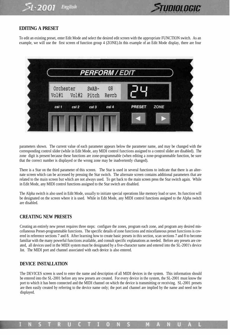
To edit an existing preset, enter Edit Mode and select the desired edit screen with the appropriate FUNCTION switch. As anexample, we will use the first screen of function group 4 (ZONE).In this example of an Edit Mode display, there are four
parameters shown. The current value of each parameter appears below the parameter name, and may be changed with thecorresponding control slider (while in Edit Mode, any MIDI control functions assigned to a control slider are disabled). Thezone digit is present because these functions are zone-programmable (when editing a zone-programmable function, be surethat the correct number is displayed or the wrong zone may be inadvertently changed).
There is a Star on the third parameter of this screen. The Star is used in several functions to indicate that there is an alter-nate screen which can be accessed by pressing the Star switch. The alternate screen contains additional parameters that arerelated to the main screen but which are not always used. To get back to the main screen press the Star switch again. Whilein Edit Mode, any MIDI control functions assigned to the Star switch are disabled.
The Alpha switch is also used in Edit Mode, usually to initiate special operations like memory load or save. Its function willbe designated on the screen where it is used. While in Edit Mode, any MIDI control functions assigned to the Alpha switchare disabled.
CREATING NEW PRESETS
Creating an entirely new preset requires three steps: configure the zones, program each zone, and program any desired mis-cellaneous Preset-programmable functions. The specific details of zone functions and miscellaneous preset functions is cov-ered in reference sections 7 and 8. After learning how to create basic presets in this section, scan sections 7 and 8 to becomefamiliar with the many powerful functions available, and consult specific explanations as needed. Before any presets are cre-ated, all devices used in the MIDI system must be designated by a five-character name and entered into the SL-2001's devicelist. The MIDI port and channel associated with each device is also entered.
DEVICE INSTALLATION
The DEVICES screen is used to enter the name and description of all MIDI devices in the system. This information shouldbe entered into the SL-2001 before any new presets are created. For every device in the system, the SL-2001 must know theport to which it has been connected and the MIDI channel on which the device is transmitting or receiving. SL-2001 presetsare then easily created by referring to the device name only; the port and channel are implied by the name and need not bedisplayed.

INPUT DEVICES
Keyboards, MIDI guitars, drums, or other controllers are input devices. As an example we will install a MIDI keyboard whichhas been plugged into input A of the SL-2001. We will assume that the keyboard is set to transmit on MIDI channel numberone. While in Edit Mode (red light on EDIT switch is on) access the DEVICES screen by pressing function switch 2
1. Using Control Slider 2, set the Port parameter to IN A. This means that the keyboard we are installing is physically con-nected to MIDI IN A of the SL-2001.
2. Adjust Control Slider 3 until the Channel parameter is on 1. This signifies that the keyboard has been set to transmit infor-mation to the SL-2001 on MIDI channel 1.
3. Once the Port and Channel are properly set, the device name can be entered by pressing the Star switch.

The device name will be entered on the second line of the text display, starting at the far left end. The flashing "A" indicatesthe current position of the cursor. Adjust Control Slider 1 until the desired character appears. Note that when the slider ismoved to the extreme upper or lower end, a new set of characters is accessible. Reversing the direction of slider motion andmoving back to the top or bottom end will enable access to the previous set of characters. The characters available for devicenames (and preset names) include the complete alphabet in upper and lower case, numerals 0 through 9, and a variety ofpunctuation marks and special symbols. These characters may also be entered by pressing the appropriate keys on the SL-2001 keyboard.
To change the position of the cursor, use the left and right arrow keys C ). There are a total of five characters availablefor the name. When the name has been completely entered, press the Star switch to return to the main screen. The screenwill now display the name as it was just entered, along with the port and channel number.To install a second device (for example, another keyboard on MIDI IN B) adjust the port and channel values as necessary,press the Star switch, and enter the name of the new keyboard. The SL-2001 local keyboard is designated by the device name"2001"; this name may not be edited or deleted. Additional keyboards in your system may be conveniently named Kybd2,Kybd3, or you may choose to use the model name or number.
OUTPUT DEVICES
Synthesizers, sound modules, percussion modules, and other sound generators are output devices. Installation of thesedevices follows the same procedure, except that additional information must be entered to describe the device. As an exam-ple, we will install a MIDI sound module on MIDI OUT A, channel 1. Adjust the port and channel values as necessary andpress the Star switch to access the alternate screen.
As before, the 5-character device name is entered using Control Slider 1 to select the character and the arrow switches tomove the cursor position (characters may also be selected by pressing the appropriate keys on the SL-2001 keyboard).Because we are installing an output device (MIDI OUT A was selected as the port) there are two additional parameters thatmust be set.
The Prg (program) parameter has two values: Zone and Auxiliary. For synthesizers or any other sound generators, this para-meter should be set for Zone. This means that each sound module receives MIDI program change commands from the asso-ciated zone that controls it.
AUXILIARY DEVICES
Some MIDI devices (such as audio effects units or programmable EQ units) do not require MIDI note or controller informa-tion, they need only to receive a MIDI program change command. For this type of auxiliary device, there is no need to ded-

icate an entire zone just to send program change commands. The SL-2001 has the ability to send simple MIDI programchange commands to eight auxiliary devices. Selecting the Aux option (csl 2) identifies the MIDI device as an auxiliary unitwhich will receive MIDI program change commands independently of the zones (although a zone may still be assigned toan Aux device if desired). The eight devices designated as auxiliary units will appear on the AUX PROG screen, where thedesired program change values may be entered (see section 7 for further information).
The Format parameter refers to the arrangement of presets on the MIDI device being installed. There are four preset formatsin common use: MIDI, MIDI+1, Bank, and Alpha.
MIDI: Presets on the instrument are numbered starting with program 0 (zero) and increase by single steps. Example: 0,1,2,3, 4, 5, 6,7,8,9,10,11,12, etc.
MIDI+1: Presets on the instrument are numbered starting with program 1 and increase by single steps. Example: 1, 2, 3, 4,5,6, 7,8,9,10,11,12, etc.
Bank: Presets are arranged in banks, with eight presets per bank. The first digit of the preset specifies the bank, and the sec-ond digit specifies the preset within the bank (this is the format used on the SL-2001). Example: 11,12,13,14,15,16,17,18,21, 22, etc.Alpha: Presets are designated by a letter plus a number from one to eight. Example: Al, A2, A3, A4, A5, A6, A7, A8, Bl, B2,etc.By setting the Format parameter to match the instrument being installed, the SL-2001 will be able to display program changesettings on the edit screens in the proper format. This greatly simplifies programming of presets; if you know that a particu-lar string preset on a synthesizer is in bank 2 preset number 1, you do not need to know that this is actually equivalent toMIDI program change command 8.
After the device name has been entered and the program and format parameters have been set, press the Star switch to returnto the main screen. The new device will now be displayed with the port and channel as programmed.
Repeat the installation procedure for all devices in the system. If you have a multi-timbral sound module, each channel ofthe instrument must be installed as a separate device. As an example, if sound module XYZ can play two sounds at once,install device XYZ1 and XYZ2 into the SL-2001 device list.
Once all devices have been installed, it is possible to review the list of devices at any time. The first three control sliders areall active on the main screen. Moving Control Slider 1 scrolls through the list of all device names. The port and channel willchange to match the values chosen when the device was installed. Moving the port (or channel) slider will likewise causethe device name to change accordingly.
NOTE: To change the port and channel for a device after it has been installed, it is necessary' to delete the device (using theAlpha switch} and re-install it. Clanging the name, Prg parameter or Format parameter/or a device dues not require dele-tion. Select the device on the main screen, then press the Star switch to access the alternate screen for editing.
ZONE CONFIGURATION
The first step in creating an entirely new SL-2001 preset is the configuration of the zones. Each zone functions as a linkbetween the keyboard and an output device (a sound module). For each zone that will be used in the preset, the input andoutput must be assigned to the desired devices. Enter Edit Mode and press FUNCTION switch 4 to access the ZONE screen.The zone digit will display the number of the zone to be edited, and may be changed with the left and right arrow switches.
In normal operation, a zone receives MIDI data on only one specific channel, processes the data, and sends the data to a SL-2001 output on a single MIDI channel. The source and destination for the zone are selected by choosing a device name fromthe SL-2001 device list. The actual SL-2001 port and channel number need not be specified, as they are implied by the devicename,
Multiple zones can be assigned in any combination to the SL-2001 keyboard or external keyboards. Up to eight sounds maybe controlled simultaneously, each with fully independent key range, dynamics, transpose, etc.

The example screen above shows Zone 1 configured to pass MIDI information from a keyboard (Kybd2) to a sound mod-ule (Mod#3). To change the zone's input assignment, move Control Slider 1 until the desired device name appears. Tochange the zone destination, move control slider number 2.
A zone may be programmed to operate only in a specific region of the master or external keyboard. Use Control Slider 3 toset the lowest desired note, and Control Slider 4 to select the highest note desired. This range may also be programmed byselecting the notes on the keyboard for that zone. Press the Star switch to access the alternate screen.
Press the two keys that correspond to the highest and lowest notes desired for the zone. You must play these notes on theinstrument specified on the screen. After the second note is pressed, the display will automatically revert to the main ZONEscreen with the new settings as programmed. -.
For the majority of presets, one zone will be used for each MIDI sound module in the system. To aid in programming andmodifying presets, try to always assign zones to sound modules in the same order. Any remaining zones are free to be usedfor special applications and effects, for example, MIDI echo.
After assigning the zone inputs and outputs, the zone must be enabled with the front-panel ZONE switch. The green lightindicates that the zone is active. Note that at least one zone must be active in every SL-2001 preset, otherwise MIDI data cannot pass from the inputs to the outputs.

Many special effects can be created by using multiple zones to control a single instrument. To create an echo effect, use twozones assigned to the same input and output devices. The first zone will have delay set to zero, while the second zone is setfor the desired delay time. To create multiple echoes, use several zones, each set for a longer delay than the one before it.Decaying echoes may be produced by adjusting the velocity scaling and offset of each zone.
ZONE BYPASS
For some applications (especially with a sequencer) it is useful to bypass a zone so that all MIDI data on all channels is passedfrom an input to an output.
Use Control Slider 1 to select the desired input (IN A through IN D). By selecting an input port instead of a device name, thezone is automatically bypassed, and will pass MIDI data on all sixteen channels. Control Slider 2 is used to select the desti-nation. Notice that when MIDI input A through D is selected on Control Slider 1, the normal output devices do not appearon Control Slider 2. This is because the output device names represent one specificMIDI channel, whereas a bypassed zone passes MIDI data on ALL channels. MIDI processing functions (including the note
range) are not available for bypassed zones and their parameters will not be displayed.
ZONE PROGRAMMING
Once the zones have been configured and enabled, the SL-2001 functions as a programmable MIDI patch bay. MIDI mes-sages from the master keyboard or external keyboards may be routed to multiple sound modules under full programmablecontrol. The next step is to program the many zone functions which make the SL-2001 a very powerful master keyboard.
The Program, Volume, and Transpose functions are fundamental to every SL-2001 preset. They permit initialization of theprogram number, volume level, and transpose interval for each sound module used in the preset. To access these functions,use FUNCTION switch 5, 6, or 7. Refer to section 8 for a detailed explanation of these functions.
The following additional functions are available for each zone (refer to section 8 for details):
ZONE CTL Selects a footswitch or panel switch that will turn the zone on or off.
DELAY The data passing through a zone may be delayed from 0 to 10 seconds.
VELOCITY Modifies the velocity value of note events.
NOTES Selects the note-assignment mode of the zone.
VOLUME CTL Assigns a slider, wheel, or voltage input to control the volume of the sound module.
KEY HOLD Creates a Sostenuto effect for the zone.
CHORD Adds up to three additional notes to each note received by the zone.
CONTROLS Programs wheels, sliders, key pressure (if so equipped), voltage inputs, and panel switches to issueany desired MIDI control change message.
MIDI cc Programs the zone to filter, scale, or map external MIDI continuous controller messages.
MIDI sw Programs the zone to filter, scale, or map external MIDI switch messages.
When creating new presets, it is possible to copy all of the parameters from one zone to another. The new zone can be quick-ly edited without having to initialize many functions. See the section below entitled Storing Presets.
MISCELLANEOUS PRESET FUNCTIONS
The final step in creating a new SL-2001 preset is to program any miscellaneous Preset-programmable functions that are need-ed. Refer to section 7 for complete information on these functions:
AUX PROG: Sends program changes to effects units, mixers, or other devices. Up to eight auxiliary programchange commands may be issued per SL-2001 preset (this is in addition to the eight programchanges issued by the zones).
SWITCHES: Sets the initial state and response of the 3 SL-2001 programmable switches (sw A, B, C).
PRESET: Programs the alphanumeric names for the preset and sliders.
Before storing the preset, make sure that all zone enable switches are set as desired. When the preset is selected later, zoneswill be enabled or disabled according to the state of the ZONE switches when the preset was stored (see section 8 under"ZONE Control").

STORING PRESETS
Once you have finished creating or editing a preset, it must be stored into one of the SL-2001's sixty-four memory locations(128 with memory card). While still in EDIT mode, press the STORE switch.
The display now indicates that you are ready to store the edited preset into a memory location.
To store the preset into its original location (24 in this example) press the Alpha switch. You will be prompted to press theAlpha switch again to complete the store operation. To cancel the operation, press the Star switch.
If you wish to store the edited preset into a different location, use the PRESET switches and the left or right arrow switchesto select a different destination. This new preset will be temporarily loaded so that you may be sure that it is an undesiredpreset. To store the preset into the memory card, adjust Control Slider 3 until the display reads Store Edit to Card. Press theAlpha switch as before to proceed with the store operation. When the store operation is complete, the SL-2001 will auto-matically switch to Perform Mode.
The Store function may also be used to copy presets into different locations while in Perform Mode. Operation is the sameas when storing an edit.
It is also possible to copy all parameters from one zone to another. While in Edit Mode, press and hold the ZONE switch youwish to copy from. Then press the STORE switch. Release both switches. After being prompted by a screen message, pressthe ZONE switch of the destination. After completing the copy operation, the SL-2001 will return to Edit Mode.
A store operation may be aborted at any time by pressing the STORE switch. The SL-2001 will revert back to Edit Mode orPerform Mode.
INITIALIZATION
Like any computer equipment, the SL-2001 may be adversely affected by low or noisy line voltage, high electrostatic fields,or other environmental hazards. Under extreme conditions,the unit's internal memory may be disturbed, resulting in erraticoperation. It is then necessary to re-initialize the memory to restore correct operation. This operation clears ALL presets andglobal data, therefore SL-2001 presets should always be saved on a memory card or via system-exclusive transfers. After thememory is cleared, the data can be reloaded into the SL-2001.
To initialize memory and clear all data. enter edit mode and select the MEMORY USED function by pressing function switch1 twice. Adjust control slider 4 until the display reads Erase All. Press the Alpha switch to start the operation. When the clearoperation is complete, the SL-2001 memory may be reloaded from a memory card or via MIDI system-exclusive data. ConsultSection 5 for information on memory transfers.

UTILITY FUNCTIONSThe Utility functions perform special operations that are only needed occasionally. To use a Utility function, enter Edit Modeand press FUNCTION switch 1 until the desired screen appears.
MIDI ACTIVITY
This screen is used to indicate the presence of MIDI messages on the MIDI input and output ports of the SL-2001. As a mes-sage enters or leaves a port, the letter A though D will flash briefly to indicate the activity. In the example above, a messagehas entered MIDI IN D and two other messages have been sent on MIDI OUT A and B. The MIDI Activity screen is very use-ful for checking a preset for correct operation. When the keyboard or other control source is played, check to see that datais also present on one or more output ports.
MEMORY USED

The SL-2001 uses a dynamic memory allocation scheme, which means that the storage space for a preset is dependent on thenumber of functions that are active in that preset. It is possible (but very unlikely) that the memory space will become fullbefore all presets have been programmed. The Memory Used screen displays the percentage of memory that has been pro-grammed.
The number on the second line indicates the percentage of preset storage memory that has been used. If this number everapproaches 99%, consider erasing some presets which are not needed to allow space for newer presets.This screen may also be used to erase data from memory. Use control slider 4 to select the data to be erased. Select Cardioerase the entire contents of a memory card currently inserted into the card slot (the switch on the card must be set for Enable).Select All to erase all internal presets and global variables. Select PrstXXor CardXX to erase the current preset.
If the MEMORY-USED screen is entered while a Memory Card preset is active, the indicated percentage refers to the mem-ory card space.
MEMORY TRANSFER
This utility function is used to transfer a complete set of 64 SL-2001 presets (plus all global-programmable settings) to or fromthe memory card. It is also possible to save or load SL-2001 memory to/from a computer via a system-exclusive operation.Before using the function, make sure that the card has been firmly inserted into the slot on the front panel.
Use Control Slider 1 to select either a Save or Load operation. If presets are to be saved to the card, the Write Protect switchon the card must be set to Enable. The Alpha switch is used to start execution of the operation. When finished with the cardsave operation, set the switch back to Protect.
For system exclusive transfers to a computer, first set the computer to record incoming data. The Alpha switch will start thetransmission of data. The sys-ex data will appear on all four MIDI outputs.
To load the SL-2001 memory via sys-ex, the Alpha switch must be pressed before the data is transmitted from the computer.Any of the four MIDI inputs will accept the sys-ex data.

GLOBAL FUNCTIONSFunctions in this category have parameters that are globally programmable, which means that there is only one set of valuesstored in memory. These values are not dependent on the preset that is selected; they are the same for all presets. All glob-al-programmable parameter values are stored permanently in memory, even if power to the SL-2001 is switched off. Any timea Global-programmable parameter is changed, the new value is automatically saved in memory; there is no need to use theStore Function with any Global-programmable parameter. The new value will remain in memory until edited again.
To modify any Global-programmable functions, enter Edit Mode and press FUNCTION switch 2 until the desired screenappears.
DEVICES
The Devices screen is used to enter the name and description of all MIDI devices in the system under control of the SL-2001.This information should be entered into the SL-2001 before any new presets are created. A detailed explanation of the deviceinstallation procedure appears in Section 4.
CHAIN
The Chain screen is used to program sequences of SL-2001 presets. A double footswitch connected to the INC/DEC input isused to step through the sequence in either direction.
Control Slider 1 is used to select the chain to be programmed or activated. There are twenty-six separate chains available (Athrough 2) with eight steps per chain. Use Control Slider 2 to select the chain step number, and Control Slider 3 to set thepreset number for that step. Once all steps have been programmed, select the chain and step number as desired. When theSL-2001 is returned to Perform Mode, the selected chain will be active. The current chain letter and step number will appearin the top right corner of the text display. Pressing the INC footswitch at the end of a chain will cause the chain to looparound to step number 1.
PRESET-CHANGE ENABLE
If the SL-2001 presets are to be selected via MIDI program change commands, it is necessary to specify the source of thesecommands..

Control Slider 1 is used to enable SL-2001 preset changes via MIDI program change commands. Slider 3 is used to select thedevice from which the SL-2001 will accept program change commands. Program changes from all input devices will beaccepted by selecting All on Slider 3.
The Conditional Preset Change function allows the SL-2001 preset change to be delayed if there are currently notes held (orif the sustain pedal is pressed) on the keyboard. The conditional function may also be used with external keyboards. Assoon as the notes (and pedal) are released, the SL-2001 will change to the selected preset. The Conditional Preset Changefunction applies to the front-panel PRESET switches as well as a preset-change command from any source (MIDI IN A throughD, Inc/Dec). During the time that the preset change is delayed, the Preset digits will flash until the conditions are met. Ifdesired, the conditional program change may be forced by using the All-Notes-Off function (press the Edit and Store switch-es simultaneously).
PRESET FUNCTIONS
The Preset Functions have a different value for each SL-2001 preset. After any Preset-programmable function is edited, theStore function must be used to save the changes in the preset. Enter Edit Mode and press FUNCTION switch 3 until thedesired screen appears. The Preset digits will be displayed to indicate the location being edited.
PRESET
Every preset on the SL-2001 may be designated by a 10-character name. This name appears on the text display duringPerform Mode. The Preset screen is used to enter the desired name.

Upon entering this screen, a flashing character will indicate the current position of the cursor. Use Control Slider 1 to selectthe desired character for this position, or press the appropriate key on the SL-2001 keyboard.. To change the position of thecursor, use the left and right arrow switches (< >).
Each SL-2001 preset also includes a programmable text line which is used to indicate the function of the control sliders dur-ing Perform Mode. There are twenty-four characters available on the bottom line of the display for this purpose. If desired,this text line may be alternately used for any general notes or information concerning the preset (for example, to identify thefunction of the footswitches). Use the Star switch to access the alternate screen. The text is entered using Control Slider 1and the left and right arrow ( ) switches.
AUX PROG
During the Device Installation procedure (section 4) up to eight devices may be designated as Auxiliary devices. An Auxiliarydevice is any MIDI device that does not require note or controller information, only program change messages (for example,a reverb unit, programmable EQ, or a MIDI lighting controller). The Auxiliary Program function is used to issue programchange commands while leaving the zones free for controlling sound modules.

The top line of the screen displays the names of the Auxiliary devices (the letter A in the lower corner distinguishes this screenfrom the Program, Volume, and Transpose screens which are very similar in appearance). Control Sliders 1 through 4 areused to select the program number that will be issued to each device as the SL-2001 preset is entered (program changes willbe issued as the sliders are adjusted). These program numbers should match the numbers displayed by each actual MIDIdevice; if not, the program format was incorrectly entered during device installation (see section 4). If no program change isdesired, adjust the slider until two dashes appear under the device name. To select program numbers for devices five througheight, use the Star switch to access the alternate screen. Unlike the Program, Volume, and Transpose screens (section 8), theorder of the names has no correlation with the Data Paths. If there are less than five Auxiliary devices, the alternate screenwill not be displayed.
SWITCH MODES
The SL-2001 provides five local switches which may be programmed to perform many useful functions during Perform Mode.Each switch (A, B, C, Star, and Alpha) may be set for either a momentary response or toggle mode. In Perform Mode the cur-rent state of all switches is displayed on the SL-2001 front panel. Switches A, B, and C appear in the text display; the Star andAlpha switches each have LED indicators.
Use Control Slider 1 to select the name of the switch. Control Slider 2 sets the mode (Toggle or Momentary). In Toggle Mode,a switch will change state every time the footswitch is pressed and released. In Momentary Mode, the switch will changestate when the footswitch is first pressed, and then revert to its original state when the footswitch is released. Control Slider3 is used to set the initial state of each switch as the preset is entered.
ZONE FUNCTIONSThe zone functions contain a separate set of parameters for each zone. This means that every SL-2001 preset has eight sep-arate storage areas to save the parameters for each zone. Whenever a zone-programmable function is edited, the zone digit(s)will appear after the Preset digits. Always check the zone display before editing any parameters, otherwise you might beginto modify the wrong zone. The best way to identify the current zone is to temporarily go to the ZONE function screen (FUNC-TION switch 4) and check the output device to which it is assigned. Use the left or right arrow (< > ) switches to changeszones if necessary. Also check that the zone you are editing is active (the indicator on the ZONE switch must be lit) so thatthe results of the edit will be audible.
Once all zones have been edited or programmed as desired, the Store function must be used to save the changes into a SL-2001 preset. The zone copy function is useful tor creating presets, as many zones will have similar parameters (see section4 under "Storing Presets").
To modify a zone-programmable function, enter Edit Mode and select the desired screen using FUNCTION switches 4through 8.
ZONE
The SL-2001 operates by routing MIDI data from the master (or external) keyboards to the sound modules via eight MIDIprocessors or "zones". To establish these links, the zones must be configured to receive the information from the perfor-mance device and send it the output devices. \
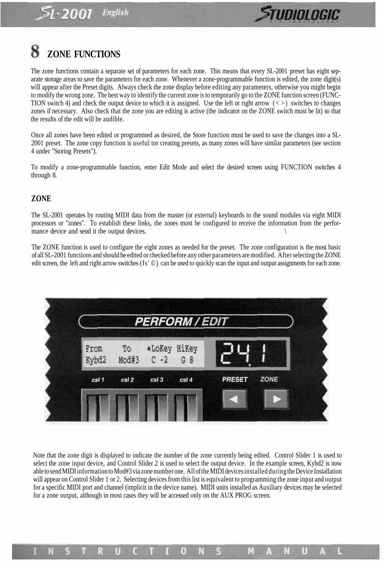
The ZONE function is used to configure the eight zones as needed for the preset. The zone configuration is the most basicof all SL-2001 functions and should be edited or checked before any other parameters are modified. After selecting the ZONEedit screen, the left and right arrow switches (fs' ©) can be used to quickly scan the input and output assignments for each zone.
Note that the zone digit is displayed to indicate the number of the zone currently being edited. Control Slider 1 is used toselect the zone input device, and Control Slider 2 is used to select the output device. In the example screen, Kybd2 is nowable to send MIDI information to Mod#3 via zone number one. All of the MIDI devices installed during the Device Installationwill appear on Control Slider 1 or 2. Selecting devices from this list is equivalent to programming the zone input and outputfor a specific MIDI port and channel (implicit in the device name). MIDI units installed as Auxiliary devices may be selectedfor a zone output, although in most cases they will be accessed only on the AUX PROG screen.

A zone may be programmed to operate only in a specific region of the master or external keyboard. Use Control Slider 3 toset the lowest desired note, and Control Slider 4 to select the highest note desired. This range may also be programmed byselecting the notes on the keyboard for that zone. Press the Star switch to access the alternate screen. Press the two keysthat correspond to the highest and lowest notes desired for the zone. You must play these notes on the instrument specifiedon the screen. After the second note is pressed, the display will automatically revert to the main ZONE screen with the newsettings as programmed.
In some applications it may he desirable to pass MIDI information on all 16 channels directly from one MIDI input to a MIDIoutput. If a zone is bypassed in this manner, none of the MIDI processing functions are available; the zone functions onlyto direct the data to a specific output.
To bypass a zone, use Control Slider 1 to select an input port. Control Slider 2 will now display only the four output ports Athrough D. The note range parameters do not apply to a bypassed zone and are not displayed. The only other function avail-able is ZONECTL.
ZONE CTL
The eight ZONE switches on the SL-2001 front panel may be used at any time to activate or disable a zone.

While creating or editing a preset, it is often desirable to turn off some of the zones so that the effects of the edit are moreclearly audible.The zones may also be controlled by the five local switches (A, B, C, Star, and Alpha). The ZONE CTL screenis used to select the source of control for the zone.
Use Control Slider 1 to select any of the local switches as a control source for the zone. If None is selected, the state mayonly be changed using the front-panel ZONE switch.
Control Slider 2 is used to select the control polarity. A positive (+) polarity means that when the switch controlling the zoneis on, the zone will be enabled. If a negative polarity is selected, turning on the control switch will disable the zone. By set-ting one zone for positive control and a second zone for negative control, the zones will alternate. This is useful for switch-ing between two different MIDI sound modules without having to use a second SL-2001 preset.
DELAY
All messages entering a zone may be delayed before they are sent to the SL-2001 output.
Use Control Slider 1 to select the delay time. This value will be displayed as milliseconds (mS, one thousandth of a second)or as seconds. Maximum delay setting is 10 seconds.
Many unique special effects may be created using multiple zones. Slapback echo, decaying echo, rhythmic echo, arpeggia-tion, and many other effects can be produced using the delay, velocity, transpose, and other zone parameters. It is even pos-sible to separate MIDI note messages from controller messages using two zones, and apply a different amount of delay toeach message type. The zone copy function is useful in creating these effects, as each zone used for the effect will be near-ly identical.
The delay function is not available for zones that are bypassed, and the parameter values are not displayed.
PROGRAM
The most fundamental parameter in a MIDI system is the program number for each device. The PROGRAM screen is usedto specify the program number issued to each device at the instant a SL-2001 preset is selected.

The PROGRAM screen (and also VOLUME and TRANSPOSE screens) display settings for four zones at once. Note that thereare now two zone digits (14) indicating that you are viewing zones 1 through 4.
The top line of the display shows the output devices to which zones one through four are assigned. The bottom line indi-cates the number of the program that will be selected on each device as a SL-2001 preset is entered (the letter P distinguish-es this screen from the VOLUME, TRANSPOSE, and AUX PROG screens). Use the four control sliders to adjust the programnumbers. Program change commands will be issued as the slider is moved. If no program number initialization is desired,adjust the control slider until two dashes appear under the device name. Setting the slider to this position will also enableexternal program change commands to pass through the zone (as long as they are on the same MIDI channel and input portas the zone). The format of each program number is determined by the Format parameter in the Device Installation (Star)screen. These numbers should therefore appear exactly as they do on the front panel of the actual MIDI devices.
If a zone is bypassed, the top line of this screen will indicate the output port to which the path is assigned. Program changecommands cannot be issued from a bypassed zone.
In the example screen, zone four is assigned to a device called Rvrb (for Reverb). Normally, a reverb or other effects unitwould be installed as an auxiliary device (see section 6). This would still allow MIDI program initialization of the device,leaving the zone free for other functions. Some more sophisticated audio effects units are able to respond to MIDI controlchange commands (for example, the wet/dry mix on a reverb unit). In this case, we would use a zone so that the reverbparameter can be controlled in real time using one of the SL-2001 local controllers or a MIDI control (see section 8).
To select program numbers for devices assigned to zones five through eight, press the right arrow switch (>) ; the zone dig-its will display 58. If more than one zone is assigned to the same output device, the program number may only be enteredfor the first zone connected to the device; the program numbers will be blank under the duplicate names. This prevents con-flicting program numbers from being sent to one device.

VELOCITY
The Velocity edit screen contains all parameters related to the velocity value of a MIDI note message.
Control Slider 1 is used to set the Velocity-Switch function. This function filters out MIDI note messages based on their veloc-ity value. When set to All, note messages will pass through the zone regardless of their velocity value. Other settings willonly pass note messages that are above or below a certain velocity value (the range of velocity values for a note-on messageis 1 to 127). The velocity-switch function can be set to pass only notes of velocity greater (or less than) l6,32,48,64,80,96,or 112. Using the velocity-switch function on two zones simultaneously, the performer can switch between two differentsounds by varying the keyboard playing force. Several zones may be set for increasing switch values, which would allowthe performer to bring in up to eight separate sound layers as the keyboard is played more forcefully.The Curve, Scale, and Offset parameters are used to modify the dynamic response of a velocity-sensitive sound module. Thishas the effect of changing the "feel" of the MIDI control keyboard. The velocity values for note-on messages may be trans- .lated via four different curves. This translation affects the dynamic response by modifying each velocity value before it is sentto the sound module. The four curves available are Linear, Shelf, ^Exponential, and -Exponential.

The graphs show the relationship between the velocity value received by the zone input and the velocity value sent to theSL-2001 output. The Linear curve does not translate the velocity value; the output value is identical to the input. The Shelfcurve has the effect of compressing the middle velocity range so that the output values tend towards the center of the range(64). The two exponential curves will have the greatest effect on the "feel" of a MIDI keyboard. Use the other velocity para-meters together with the curve parameter to experiment with the dynamic response.
The Scale parameter is used to expand or shrink the dynamic range of a sound module. A scale factor of 100% will have noeffect; increasing or decreasing this setting will have a corresponding effect on the dynamic response. Negative scale factorsare also available which will produce decreasing output velocity values for increasing input velocities. Two zones set forpositive and negative scale factors can produce a velocity cross-fade effect, where the mix between two sound modules iscontrolled by the playing force on the keyboard.
The Offset parameter is used to add a constant value to the note-on velocity. This will have the effect of increasing (ordecreasing) the velocity (and therefore the loudness) of a note over the entire dynamic range. For decaying echo effects, useseveral delayed zones assigned to the same sound module, and offset each zone by a more negative value.
The Velocity functions are not available if the zone is bypassed, and the parameter values are not displayed.
NOTES
The NOTES function affects the way in which MIDI note events pass through a zone. They may be completely blocked, or
notes may be selectively filtered in many useful ways.Control Slider 1 selects various note filters. To pass all MIDI note events, adjust the slider to On. To block all note events forthe zone, select Off. Two additional settings allow only odd-numbered or even-numbered notes to pass (middle "C" is notenumber 60). The "Kmap" setting is a special filter in which all 128 MIDI note numbers may be designated to be blocked orpassed. Use the Star switch to access the alternate screen and program the key map.

There are two ways to program the Key Map function. Control Slider 1 may be used to select a note, and Control Slider 2determines if the note is On (passed) or Off (filtered). Alternately, the key map may be directly programmed from the key-board. Press the Alpha switch to clear the key map and enable programming. As notes are played on the keyboard, eachnote name will appear under Key*, and the Stat parameter will be set to On. Once all desired keys have been pressed, pressthe Alpha switch again. The key map may be edited during or after loading using Control Sliders 1 and 2.
The second parameter on the main NOTES screen is the Note Assignment Mode. The normal setting for this parameter is Poly(polyphonic). This mode allows multiple MIDI note-on messages to pass through the zone, which means that many notescan be played simultaneously on the MIDI sound module. Three other monophonic note assignment modes are availablewhich only allow one note at a time to sound. LoNote only passes the lowest note received; if a new key is pressed whichis lower than the current low key, the new note will sound and the old note will turn off. HiNote only allows only the high-est note to pass through the zone, and LstNt allows only the last note. The note assignment modes are very useful for livekeyboard performance. The performer may control three or four distinct sounds from the keyboard at once.
The NOTES functions are not available if the zone is bypassed, and the parameter values are not displayed.
VOLUMEAnother very basic parameter in a MIDI system is the volume setting of all devices. The VOLUME screen is used to specify

the MIDI volume messages that are sent to each device when SL-2001 preset is selected.As in the PROGRAM screen, the top line displays the names of the devices (or ports) controlled by zones one through four.The bottom line shows the value of the MIDI volume control message that will be issued as the SL-2001 preset is selected.Use the four control sliders to adjust the initial volume setting for each device (the initial volume message is transmitted asthe slider is changed, which allows the relative volumes of all devices to be easily adjusted by ear). The initial volume para-meter has a range of zero to 127. If no volume initialization is desired, adjust the control slider until two dashes appear underthe device name. For best signal-to-noise ratio, at least one of the zones should be set to maximum, and the others adjustedbelow it to achieve the proper mix.
To select initial volumes for devices assigned to Paths five through eight, press the right arrow switch ( > ) ; the zone digitswill then display 58. If more than one zone is assigned to the same output device, the initial volume value may only beentered for the first zone connected to the device; the volume values will be blank under the duplicate names. This preventsconflicting volume messages from being sent to the same device.
If a zone is bypassed, its output port will be displayed. Volume initialization commands can not be sent from a bypassed path.
VOLUME CONTROL
Volume control is an essential means of expression in music performance. Each zone (and therefore each sound module)may be programmed to respond to volume adjustments from a SL-2001 control slider, voltage (pedal) input, or any MIDI con-troller (e.g., a mod wheel).
Control slider 2 is used to select the source of volume control. Select from any of the four control sliders (in Perform Mode),control voltage input 1 or 2, Wheel A or B. If no adjustments are required during performance, select None.Control Slider 2 selects the polarity. Positive (+) polarity means that an increasing controller value (e.g., pressing a voltagepedal forward) results in an increasing volume. Negative polarity (-) means that an increase in controller value results in avolume decrease. The polarity function can therefore used to cross-fade between two different sound modules as the sourcecontroller is moved through its range. Set the polarity for one zone to positive, and the polarity another zone to negative toachieve a cross fade. Since up to eight zones may be active at once, two multi-layer sounds may be cross faded.
The Volume Control function interacts with the settings on the main Volume screen. The volume control source is automat-ically scaled by the initial volume setting. Moving the source controller (for example, a foot pedal) from zero to maximumwill result in a volume change from zero to the initial value set on the Master Volume screen. This automatic scaling featuremaintains the relative audio mix between all of the sound modules as the volume is changed. The effect is the same as if aconventional mechanical volume pedal were used to adjust the volume of an audio mixer output.

By using the SL-2001 instead, the noise and reliability problems of a mechanical volume pedal are eliminated. The diagrambelow illustrates the volume control function in a preset using three zones.
Three zones are active in this example. The initial volumes have been programmed on the VOLUME screen to achieve thedesired relative mix. If the source controller (usually a foot pedal connected to cv 1 or 2) is at the top of its range, the threesound modules will remain at the initial volume levels. As the pedal is moved downward, volume messages are issued toeach of the three sound modules. The relative mix between the sounds is retained, until eventually all volume levels reachzero. Variations among different sound modules and manufacturers can cause slight volume mistracking as the controller ismoved; initial volumes may have to be adjusted for the best response over the range of interest.
The volume control function is not available if the zone is bypassed, and the parameter values are not displayed.
KEY HOLD
The KEY HOLD function is used to produce the same effect as the Sostenuto pedal on a grand piano.

Control Slider 2 turns on the Key Hold function. Select a control source using Slider 3. The control source will usually beassigned to one of the local switches A, B, or C, and activated with the footswitch.
To use the Key Hold function, first press and hold a key (or keys) on the keyboard. Next, press the control switch. The keysmay now be released, but they will continue to sound as long as the control switch is on (if the control switch is set formomentary mode, it must be held down to sustain the notes; if it is set for toggle mode, it may be released). Any new keysplayed at this time will not sustain. The sustaining notes will stop sounding as soon as the control switch is turned off.
A variation of Key Hold is activated by switching Control Slider 2 to Latch. Operation is similar to normal mode, except thatwhen a chord is being sustained by the control switch, any new keys pressed will be locked out, and only the chord will con-tinue to sound. On some MIDI sound modules, restriking the keys held by the Key Hold function will cause the notes to turnoff. Most modules will assign additional voices at the same pitch of the sustained notes.
The Key Hold function is not available if the zone is bypassed.
TRANSPOSE
When creating a layered sound using several MIDI synthesizers or sound modules, the relative pitch of each layer has a majoreffect on the overall sound. The TRANSPOSE screen is used to adjust the transpose interval for each sound module. The topline displays the names of the devices controlled by zones one through four. The bottom line shows the transpose interval
for each zone. The transpose value has a range of +/- 60 semitones (equal to +/- five octaves). Use the value zero if no trans-position is desired.
It is possible that several zones may be assigned to the same sound module. The transpose parameter may be set to a dif-ferent value for each zone. This means that playing one note on the MIDI keyboard could produce a chord on a single soundmodule (however it is more efficient to use the SL-2001 Chord function than to use multiple zones).
To set transpose intervals for zones five through eight, press the right arrow switch ( > ) ; the zone digits will display 58.
If a zone is bypassed, the output port will be displayed. The transpose function does not operate when^he zone is bypassed.

CHORD
The CHORD function is used to create multiple note messages from a single note message.
If Control Slider 2 is changed from the Off position, a second note message will be created for every note message receivedby the zone. A third and fourth note may be introduced using Control Sliders 3 and 4. The control slider settings determinethe transpose interval for each of the additional notes. This interval is added to the overall transposition value set in theTRANSPOSE screen. Any notes that are transposed out of the normal MIDI note range will not sound.
It is possible to produce more note-on messages than can be sounded simultaneously on the sound module; the keyboardshould be played accordingly. Note that a zero setting is available which produces a new note message identical to the onereceived. On some synthesizers and sound modules, duplicate note messages will have no effect. When the Chord functionis not used, be sure that Control Sliders 2, 3, and 4 are set to the Off position.
The Chord function is not available if the zone is bypassed, and the parameter values are not displayed.
SPECIAL
The SPECIAL screen is reserved for new functions which may be available in future versions of the SL-2001 operating soft-ware. Consult your dealer for information about software updates.
CONTROLS
The final group of SL-2001 edit screens contain all functions relating to the processing of MIDI control change messages bythe zone. If a zone is associated with the SL-2001 keyboard, all control change messages will originate from the SL-2001 localcontrols (wheels, switches, sliders, etc.). The CONTROLS screen is used to assign the local controls to various destinations.
If a zone is associated with an external keyboard, control change messages originate from that instrument. The MIDI cc (con-tinuous controller) and MIDI sw (switch) screens are used to assign these externals controllers (wheels, knobs, switches, etc.)to various destinations.
The MIDI cc and MIDI sw screens do not function for zones associated with the SL-2001 keyboard, however the CONTROLSscreen may be used even for zones associated with external keyboards. Messages from the SL-2001 local controls will bemerged with the external MIDI data You may, for example, have a keyboard without Pitch and Modulation wheels.
The SL-2001 wheels could be used to add this controller information to the note information coming from the external key-

board. None of the three controller screens function if the zone is bypassed.
Control Slider 1 is used to select among the SL-2001 local controllers:
Wheel A, B The left control and right control wheelsSstain The Sustain switch inputChPrsr Channel pressure (aftertouch)csll-csl4 The four front panel control sliderscvl-cv2 The two voltage inputssw A, B, C The three programmable switch inputssw *,a Front panel Star and Alpha switchesNote* The MIDI note number (0-127) of the last
key played on SL-2001 keyboardVel The velocity value (0-127) of the last
key played on the SL-2001 keyboard
Any control message from any source can be either passed directly to the SL-2001 MIDI outputs, converted to any other con-troller, or blocked completely. Messages may also be scaled to adjust the depth of the control effect using Control Slider 2.Use Control Slider 3 to select the destination message. If desired, any destination controller may be initialized when the pre-set is entered. Use Control Slider 4 to set the initial value to be issued. The initial value can be sent to any destination, evenif the depth setting is off.
Blank SL-2001 presets will always leave Wheel A and Wheel B programmed as Pitch and Modulation, respectively. The Sstainand Key Pressure controls also default to their respective messages.
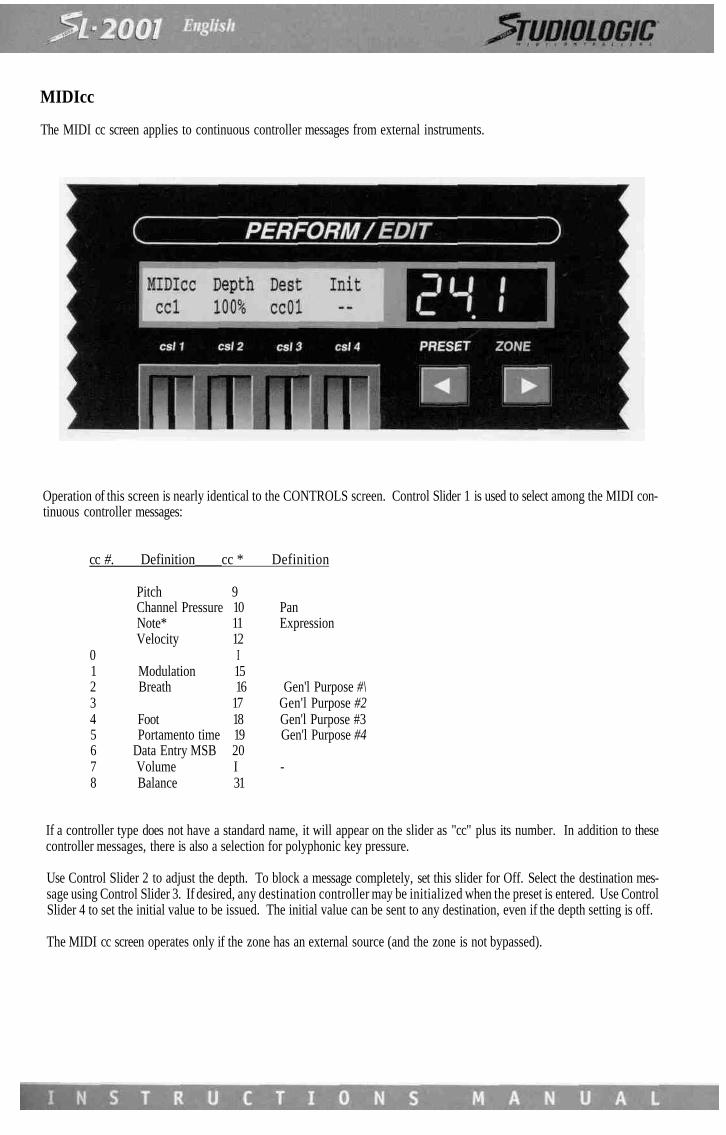
MIDIcc
The MIDI cc screen applies to continuous controller messages from external instruments.
Operation of this screen is nearly identical to the CONTROLS screen. Control Slider 1 is used to select among the MIDI con-tinuous controller messages:
cc #. Definition____cc * Definition
Pitch 9Channel Pressure 10 PanNote* 11 ExpressionVelocity 12
0 I1 Modulation 152 Breath 16 Gen'l Purpose #\3 17 Gen'l Purpose #24 Foot 18 Gen'l Purpose #35 Portamento time 19 Gen'l Purpose #46 Data Entry MSB 207 Volume I -8 Balance 31
If a controller type does not have a standard name, it will appear on the slider as "cc" plus its number. In addition to thesecontroller messages, there is also a selection for polyphonic key pressure.
Use Control Slider 2 to adjust the depth. To block a message completely, set this slider for Off. Select the destination mes-sage using Control Slider 3. If desired, any destination controller may be initialized when the preset is entered. Use ControlSlider 4 to set the initial value to be issued. The initial value can be sent to any destination, even if the depth setting is off.
The MIDI cc screen operates only if the zone has an external source (and the zone is not bypassed).

MIDIsw
The MIDI sw screen applies to switch messages from external instruments.
Use Control Slider 1 to select a MIDI switch message type:
sw # Definition_________sw # Definition
64 Sustain (damper) 81 Gen'l Purpose #265 Portamento 82 Gen'l Purpose #366 Sostenuto 83 Gen'l Purpose #467 Soft Pedal 8468 - I69 Hold 2 9170 - 92 Tremolo DepthI - 93 Chorus Depth
79 - 94 Detune80 Gen'l Purpose #\ 95 Phaser Depth
If a controller type does not have a standard name, it will appear on Control Slider 1 as csw plus its number. Use ControlSlider 2 to adjust the depth. To block a message completely, set this slider for Off. Select the destination message usingControl Slider 3. If desired, any destination controller may be initialized when the preset is entered. Use Control Slider 4 toset the initial value to be issued. The initial value can be sent to any destination, even if the depth setting is off.
The MIDI sw screen operates only if the zone has an external source and is not bypassed.

SL-2001 UPDATE SOFTWARE VERSION 2.1
Version 2.1 includes the changes listed below:
- MIDI Clock - Start, Stop - FUNCTION FOR SEQUENCERS, DRUMS MACHINES, COMPUTERS ecc..
- Direct Program Change - FUNCTION FOR FAST PROGRAM CHANGES COMMAND.
- Port/channel - UTILITY FOR CHECK THE SETTING OF DEVICE INSTALLATION (FAST MONITOR).(
- Zone Control Polarity - CORRECT FUNCTION NOW AVAILABLE IN VOLUME CONTROL PAGE.
- Sys Ex Bulk Dump MIDI Messages - FUNCTION OPTIMIZED OF Sys Ex FOR LARGE MESSAGES.

SWITCH MODES
The SL-2001 provides five local switches which may be programmed to perform many useful functions during Perform Mode.Each switch (A, B, C, Star and Alpha) may be set for either a momentary response or toggle mode. In Perform Mode the cur-rent state of all switches is displayed on the SL-2001 front panel. Switches A, B, and C appear in the text display; the Star andAlpha switches each have LED indicators.
Use Control Slider 1 to select the name of the switch. Control Slider 2 sets the mode (Toggle or Momentary).Control Slider 3 is used to set the initial state of each switch as the preset is entered.In Toggle Mode, a switch will change state every time the footswitch is pressed and released. In Momentary Mode, the swit-ch will change state when the footswitch is first pressed, and then revert to its original state when the footswitch is released.
Control slider 4 is used to select a pair of switches that will operate the SL-2001 MIDI clock generator, which is used withexternal devices like sequencers or drum machines. Two switches are required to operate the clock generator, either pair B/Cor Star/Alpha. When not in use, set csl 4 to Off. To use the clock generator, adjust csl 4 until the desiderd switch pair appears(MIDI clock pulses will now be issued continuously). In Perform Mode these two switches will issue STOP/CONTINUE andSTART messages to control an external sequencer or drum machine. The mode setting (csl 2) for the selected pair will indi-cate Clk, and the Init setting will not operate.
The star that appears after Clock indicates that the MIDI Clock generator screen may be accessed by pressing the Star switch.The TEMPO slider selects the clock rate (from 10 to 250 beats per minute). The tempo may be adjusted in Perform Mode withone of the four control sliders as indicated on csl 2. This slider will operate in relative mode, which means that the tempo willbe adjusted up or down from its initial value set by csll. Before entering any preset which uses a control slider for tempoadjustment, make sure that the slider is somewhere in the middle of its range, so that the tempo may be either increased ordecreased as the slider is adjusted.The third control slider selects a MIDI output which will transmit the MIDI real-time messages (clock, start, stop, continue).If desired, these messages can be transmitted on all four outputs at once, however it is better to connect all MIDI deviceswhich require timing information to the same output.
PROGRAM
The most fundamental parameter in a MIDI system is the program number for each device. The PROGRAM screen is used tospecify the program number issued to each device at the instant a SL-2001 preset is selected.The PROGRAM screen (and also VOLUME and TRANSPOSE screens) display settings for four zones at once.Note that there are now two zone digits (14) indicating that you are viewing zones 1 through 4.The top line of the display shows the output devices to which zones one through four are assigned. The bottom line indica-tes the number of the program that will be selected on each device as a SL-2001 preset is entered (the letter P distinguishesthis screen from the VOLUME, TRANSPOSE and AUX PROG screens). Use the four control sliders to adjust the program num-bers. Program change commands will be issued as the slider is moved.

A direct program change feature is available which allows faster access to any program number. PRESET switches 1 through8 and the left/right arrow switches are used as a keypad to enter the desired number (the left/right arrow switches representthe numerals 9 and 0). To use this feature, first press and hold the ZONE switch (1-8) that you wish to program.Enter the desired program number on the "keypad" (either one, two, or three digits). When you release the ZONE switch,the program change will be issued and the number will be updated in the display.
Note that the program numbers must be entered in the appropriate format for the output device assigned to the zone (pro-gram number formats are set on the Device Installation screen). If a device format is set to ALPHA, the PRESET switches 1through 8 correspond to letters A through H.
The direct program change feature may be used in either Edit or Perform modes (however the program numbers will not bevisible in Perform mode). Any changes made to a Zone's program settings in either mode must be stored with the SAVE func-tion, otherwise they will not be permanent.
If no program number initialization is desired for a zone, adjust the control slider until two dashes appear under the devicename. Setting the slider to this position will also enable external program change commands to pass through the zone (aslong as they are on the same MIDI channel and input port as the zone).
If a zone is bypassed, the top line of this screen will indicate the output port to which the path is assigned. Program changecommands cannot be issued from a bypassed zone.
In the example screen, zone four is assigned to a device called Rvrb (for Reverb). Normally, a reverb or other effects unitwould be installed as an auxiliary device (see section 6). This would still allow MIDI program initialization of the device, lea-ving the zone free for other functions.

Some more sophisticated audio effects units are able to respond to MIDI control change commands (for example, the wet/drymix on a reverb unit). In this case, we would use a zone so that the reverb parameter can be controlled in real time using oneof the SL-2001 local controllers or a MIDI control (see section 8).
To select program numbers for devices assigned to zones five through eight, press the right arrow switch (>); the zone digitswill display 58. If more than one zone is assigned to the same output device, the program number may only be entered forthe first zone connected to the device; the program numbers will be blank under the duplicate names. This prevents con-flicting program numbers from being sent to one device.
ZONE
The SL-2001 operates by routing MIDI data from the master (or external) keyboards to the sound modules via eight MIDI pro-cessors or "zones". To establish these links, the zones must be configured to receive the information from the performancedevice and send it the output devices.
The ZONE function is used to configure the eight zones as needed for the preset. The zone configuration is the most basicof all SL-2001 functions and should be edited or checked before any other parameters are modified.After selecting the ZONE edit screen, the left and right arrow switches (<>) can be used to quickly scan the input and outputassignments for each zone.Note that the zone digit is displayed to indicate the number of the zone currently being edited. Control Slider 1 is used toselect the zone input device, and Control Slider 2 is used to select the output device. In the example screen, Kybd2 is nowable to send MIDI information to Mod#3 via zone number one. All of the MIDI devices installed during the Device Installationwill appear on Control Slider 1 or 2. Selecting devices from this list is equivalent to programming the zone input and outputfor a specific MIDI port and channel (implicit in the name). If for some reason you need to know the actual port and chan-nel assignments for the zone, you can either check the settings on the device installation screens, or you can simply press theAlpha switch; the device names will temporarily change to show the actual port and channel assignments. MIDI units instal-led as Auxiliary devices may be selected for a zone output, although in most cases they will be accessed only on the AUXPROG screen.
A zone may be programmed to operate only in a specific region of the master or external keyboard. Use Control Slider 3 toset the lowest desiderd note. and Control Slider 4 to select the highest note desired. This range may also be programmed byselecting the notes on the keyboard for that zone. Press the Star switch to access the alternate screen. Press the two keys thatcorrespond to the highest and the lowest notes desired for the zone. You must play these notes on the instrument specifiedon the screen. After the second note is pressed, the display will automatically revert to the main ZONE screen with the newsettings as programmed.In some applications it may be desiderable to pass MIDI information on all 16 channels directly from one MIDI input to aMIDI output. If a zone is bypassed in this manner, none of the MIDI processing functions are available, the zone functionsonly to direct the data to a specific output. To bypass a zone, use Control Slider 1 to select an input port. Control Slider 2 willnow display only the four output ports A through D. The note range parameters do not apply to a bypassed zone and are notdisplayed. The only other function available is ZONE CTL.

PRESET-CHANGE ENABLE
If the SL-2001 presets are to be selected via MIDI program change commands, it is necessary to specify the source of thesecommands.
Control Slider 1 is used to enable SL-2001 preset changes via MIDI program change commands, Slider 3 is used to select thedevice from which the SL-2001 will accept program change commands. Program changes from all input devices will be accep-ted by selecting All on Slider 3.
The Conditional Preset Change function allows the SL-2001 preset change to be delayed under any of the following condi-tions:1) there are currently notes being held on the keyboard;2) the sustain pedal is currently pressed;3) one or more zones are using the delay function, and there are notes or other events which have not yet appeared on theoutput of the zone(s).
The Conditional Preset Change function applies to the front-panel PRESET switches as well as a preset-change commandfrom any source (MIDI IN A through D, Inc/Dec). During the time that the preset change is delayed, the Preset digits willflash until the conditions are met. If desired, the conditional program change may be forced by using the All-Notes-Off func-tion (press the Edit and Store switches simultaneously). If the preset change is waiting for delayed Zone events, turning offthe zone(s) will force the preset change.