introduction—electronic circuit protection esx10-t sheets/weidmuller pdfs/esx10-t.… · 42...
TRANSCRIPT
42
Introduct ion—Electronic Circuit Protect ion ESX10-T
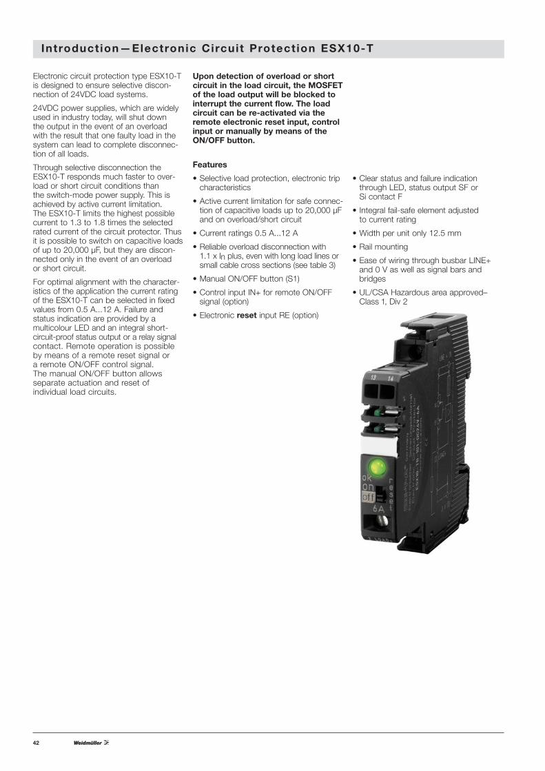
Upon detection of overload or shortcircuit in the load circuit, the MOSFETof the load output will be blocked tointerrupt the current flow. The loadcircuit can be re-activated via theremote electronic reset input, controlinput or manually by means of theON/OFF button.
Features
• Selective load protection, electronic tripcharacteristics
• Active current limitation for safe connec-tion of capacitive loads up to 20,000 μFand on overload/short circuit
• Current ratings 0.5 A...12 A
• Reliable overload disconnection with 1.1 x In plus, even with long load lines orsmall cable cross sections (see table 3)
• Manual ON/OFF button (S1)
• Control input IN+ for remote ON/OFFsignal (option)
• Electronic reset input RE (option)
• Clear status and failure indicationthrough LED, status output SF or Si contact F
• Integral fail-safe element adjusted to current rating
• Width per unit only 12.5 mm
• Rail mounting
• Ease of wiring through busbar LINE+and 0 V as well as signal bars andbridges
• UL/CSA Hazardous area approved–Class 1, Div 2
Electronic circuit protection type ESX10-Tis designed to ensure selective discon-nection of 24VDC load systems.
24VDC power supplies, which are widelyused in industry today, will shut down the output in the event of an overload with the result that one faulty load in thesystem can lead to complete disconnec-tion of all loads.
Through selective disconnection theESX10-T responds much faster to over-load or short circuit conditions than the switch-mode power supply. This isachieved by active current limitation. The ESX10-T limits the highest possiblecurrent to 1.3 to 1.8 times the selectedrated current of the circuit protector. Thusit is possible to switch on capacitive loadsof up to 20,000 μF, but they are discon-nected only in the event of an overload or short circuit.
For optimal alignment with the character-istics of the application the current ratingof the ESX10-T can be selected in fixedvalues from 0.5 A...12 A. Failure and status indication are provided by a multicolour LED and an integral short-circuit-proof status output or a relay signalcontact. Remote operation is possible by means of a remote reset signal or a remote ON/OFF control signal. The manual ON/OFF button allows separate actuation and reset of individual load circuits.

43
E lectronic Circuit Protect ion ESX10-T
Status output SF ESX10-TB-114/-124/
Electrical data plus-switching signal output,
connects Ub to terminal 12 of module 17plus
nominal data: 24VDC / max. 0.2 A (short circuit proof)
status output is internally connected to
GND with a 10 kOhm resistor
Status OUT ESX10-TB-114/-124 (signal status OUT),
at Ub = +24 V
+24 V = S1 is ON, load output connected through
0V = S1 is ON, load output blocked and/or
switch S1 is OFF
red LED lit
OFF condition 0 V level at status output when:
• switch S1 is in ON position, but device is
still in switch-on delay
• switch S1 is OFF, or control signal OFF,
device is switched off
• no operating voltage UbSignal output F ESX10-TB-101/-102
Electrical data potential-free signal contact
max. 30VDC/0.5 A, min. 10 V/10 mA
ON condition LED green voltage Ub applied, switch S1 is in ON position
no overload, no short circuit
OFF condition LED off • device switched off (switch S1 is in OFF position)
• no voltage Ub applied
Fault condition LED orange overload condition > 1.1 x In up to
electronic disconnection
Fault condition LED red electronic disconnection upon
overload or short circuit
device switched off with control signal
(switch S1 is in ON position)
ESX10-TB-101 single signal, make contact
contact SC/SO-SI open
ESX10-TB-102 single signal, break contact
contact SC/SO-SI closed
Fault signal output fault conditions:
• no operating voltage Ub• ON/OFF switch S1 is in OFF position
• red LED lighted
(electronic disconnection)
Reset input RE ESX10-TB-124
Electrical data voltage: max. +32VDC
high > 8VDC ≤ 32VDC
low ≤ 3VDC > 0 V
power consumption typically 2.6 mA
(+24VDC)
min. pulse duration typically 10 ms
Reset signal RE The electronically blocked ESX10-TB-124
(terminal 22) may remotely be reset via an external
momentary switch due to the falling edge of
a +24 V pulse.
A common reset signal can be applied to
several devices simultaneously.
Switched on devices remain unaffected.
Control input IN+ ESX10-TB-114
Electrical data see reset input RE
Control signal IN+ +24V level (HIGH): device will be switched
(terminal 21) on by a remote ON/OFF signal
0 V level (LOW): device will be switched
off by a remote ON/OFF signal
Switch S1 ON/OFF unit can only be switched on with S1 if a
HIGH level is applied to IN+
Technical data (Tambient = 40°C, operating voltage Ub = 24VDC)Approvals
Technical data (Tambient = 40°C, operating voltage Ub = 24VDC)
Authority Voltage rating Current ratings
UL2367 (E306740) 24VDC 0.5...12 A
UL1604 (E322549) 24VDC 0.5...12 A
(class 1, div. 2, group A, B, C, D)
UL508/ cUL 508 24VDC 0.5...12 A
CSA file 165971:
CSA C22.2 No: 213 (class I, div. 2) 24VDC 0.5...12 A
Groups A, B, C, D, T5
CSA C22.2 No: 142 24VDC 0.5...12 A
Class 2
Meets requirements for Class 2 current limitation
(ESX10-T... 0.5 A / 1 A / 2 A / 3 A
Operating data
Operating voltage Ub 24VDC (18...32 V)
Current rating In fixed current ratings: 0.5, 1 A, 2 A, 3 A, 4 A,
6 A, 8 A, 10 A, 12 A
Closed current I0 ON condition: typically 20...30 mA
depending on signal output
Status indication • multicolour LED:
by means of GREEN: unit is ON, power-MOSFET
is switched on
- status output SF ON,
supplies + 24VDC
ORANGE: in the event of overload or
short circuit until electronic
disconnection
RED: - unit electronically disconnected
- load circuit/Power-MOSFET
OFF
OFF: - manually switched off
(S1 = OFF)
or device is dead
- undervoltage (Ub < 8 V)
- after switch-on till the end
of the delay period
• status output SF (option)
• potential-free signal contact F (option)
• ON/OFF/ condition of switch S1
Load circuit
Load output Power-MOSFET switching output
(high side switch)
Overload disconnection typically 1.1 x In (1.05...1.35 x In)
Short-circuit current IK active current limitation (see table 1)
Trip time see time/current characteristics
for electronic disconnection typically 3 s at ILoad > 1.1 x Intypically 3 s...100 ms at ILoad > 1.8 x In
(or 1.5 x In/1.3 x In)
Temperature disconnection internal temperature monitoring with
electronic disconnection
Low voltage monitoring
load output with hysteresis, no reset required
load “OFF” at Ub < 8 V
Starting delay tstart typically 0.5 sec after every switch-on
and after applying UbDisconnection of load circuit electronic disconnection
Free-wheeling circuit external free-wheeling diode
recommended with inductive load
Several load outputs must not be connected in parallel
44
E lectronic Circuit Protect ion ESX10-T
Technical data (Tambient = 40°C, operating voltage Ub = 24VDC)
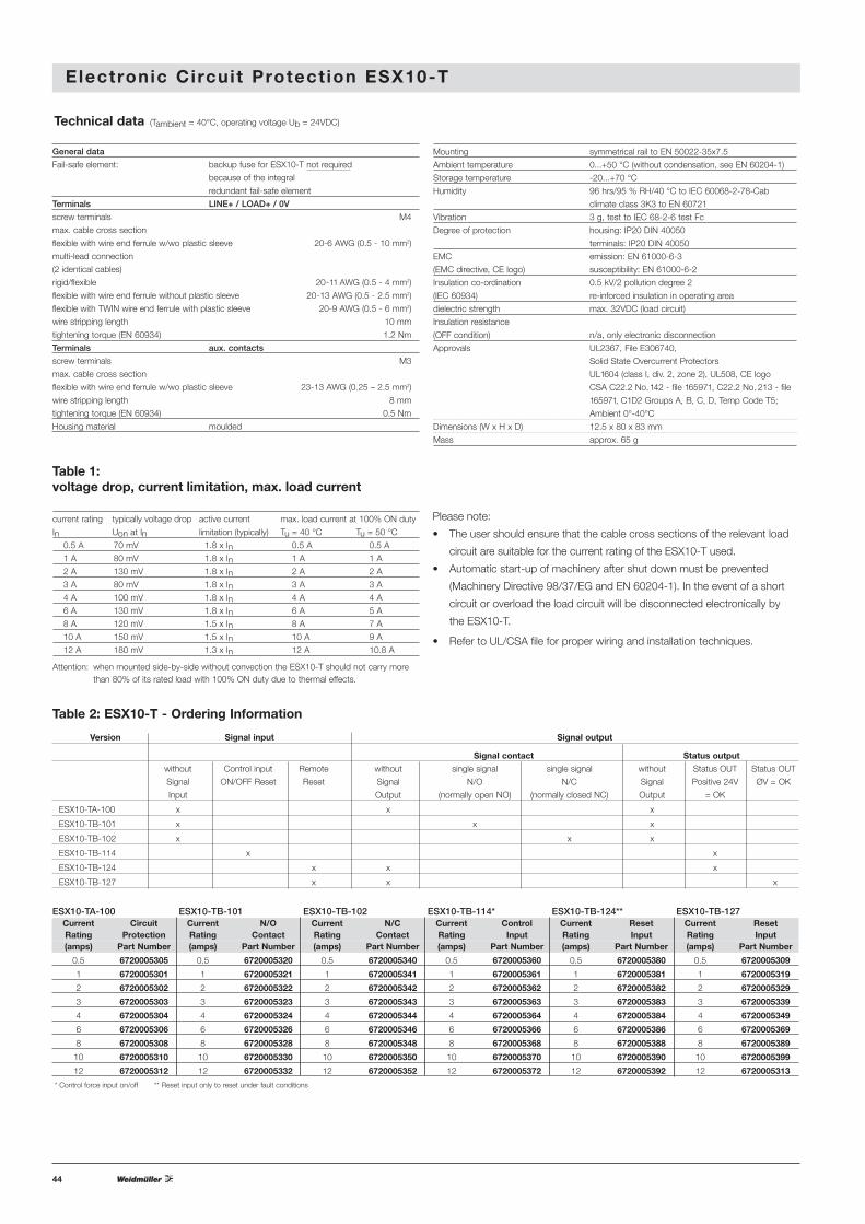
Table 1: voltage drop, current limitation, max. load current
current rating typically voltage drop active current max. load current at 100% ON duty
In Uon at In limitation (typically) Tu = 40 °C Tu = 50 °C
0.5 A 70 mV 1.8 x In 0.5 A 0.5 A
1 A 80 mV 1.8 x In 1 A 1 A
2 A 130 mV 1.8 x In 2 A 2 A
3 A 80 mV 1.8 x In 3 A 3 A
4 A 100 mV 1.8 x In 4 A 4 A
6 A 130 mV 1.8 x In 6 A 5 A
8 A 120 mV 1.5 x In 8 A 7 A
10 A 150 mV 1.5 x In 10 A 9 A
12 A 180 mV 1.3 x In 12 A 10.8 A
Attention: when mounted side-by-side without convection the ESX10-T should not carry more than 80% of its rated load with 100% ON duty due to thermal effects.
Please note:
• The user should ensure that the cable cross sections of the relevant load
circuit are suitable for the current rating of the ESX10-T used.
• Automatic start-up of machinery after shut down must be prevented
(Machinery Directive 98/37/EG and EN 60204-1). In the event of a short
circuit or overload the load circuit will be disconnected electronically by
the ESX10-T.
• Refer to UL/CSA file for proper wiring and installation techniques.
* Control force input on/off ** Reset input only to reset under fault conditions
Table 2: ESX10-T - Ordering Information
ESX10-TB-101 Current N/O Rating Contact (amps) Part Number
0.5 6720005320
1 6720005321
2 6720005322
3 6720005323
4 6720005324
6 6720005326
8 6720005328
10 6720005330
12 6720005332
ESX10-TA-100 Current Circuit Rating Protection (amps) Part Number
0.5 6720005305
1 6720005301
2 6720005302
3 6720005303
4 6720005304
6 6720005306
8 6720005308
10 6720005310
12 6720005312
ESX10-TB-102 Current N/C Rating Contact (amps) Part Number
0.5 6720005340
1 6720005341
2 6720005342
3 6720005343
4 6720005344
6 6720005346
8 6720005348
10 6720005350
12 6720005352
ESX10-TB-114* Current Control Rating Input (amps) Part Number
0.5 6720005360
1 6720005361
2 6720005362
3 6720005363
4 6720005364
6 6720005366
8 6720005368
10 6720005370
12 6720005372
ESX10-TB-124** Current Reset Rating Input (amps) Part Number
0.5 6720005380
1 6720005381
2 6720005382
3 6720005383
4 6720005384
6 6720005386
8 6720005388
10 6720005390
12 6720005392
ESX10-TB-127 Current Reset Rating Input (amps) Part Number
0.5 6720005309
1 6720005319
2 6720005329
3 6720005339
4 6720005349
6 6720005369
8 6720005389
10 6720005399
12 6720005313
Version Signal input Signal output
Signal contact Status output
without Control input Remote without single signal single signal without Status OUT Status OUT
Signal ON/OFF Reset Reset Signal N/O N/C Signal Positive 24V ØV = OK
Input Output (normally open NO) (normally closed NC) Output = OK
ESX10-TA-100 x x x
ESX10-TB-101 x x x
ESX10-TB-102 x x x
ESX10-TB-114 x x
ESX10-TB-124 x x x
ESX10-TB-127 x x x
General data
Fail-safe element: backup fuse for ESX10-T not required
because of the integral
redundant fail-safe element
Terminals LINE+ / LOAD+ / 0V
screw terminals M4
max. cable cross section
flexible with wire end ferrule w/wo plastic sleeve 20-6 AWG (0.5 - 10 mm2)
multi-lead connection
(2 identical cables)
rigid/flexible 20-11 AWG (0.5 - 4 mm2)
flexible with wire end ferrule without plastic sleeve 20-13 AWG (0.5 - 2.5 mm2)
flexible with TWIN wire end ferrule with plastic sleeve 20-9 AWG (0.5 - 6 mm2)
wire stripping length 10 mm
tightening torque (EN 60934) 1.2 Nm
Terminals aux. contacts
screw terminals M3
max. cable cross section
flexible with wire end ferrule w/wo plastic sleeve 23-13 AWG (0.25 – 2.5 mm2)
wire stripping length 8 mm
tightening torque (EN 60934) 0.5 Nm
Housing material moulded
Mounting symmetrical rail to EN 50022-35x7.5
Ambient temperature 0...+50 °C (without condensation, see EN 60204-1)
Storage temperature -20...+70 °C
Humidity 96 hrs/95 % RH/40 °C to IEC 60068-2-78-Cab
climate class 3K3 to EN 60721
Vibration 3 g, test to IEC 68-2-6 test Fc
Degree of protection housing: IP20 DIN 40050
terminals: IP20 DIN 40050
EMC emission: EN 61000-6-3
(EMC directive, CE logo) susceptibility: EN 61000-6-2
Insulation co-ordination 0.5 kV/2 pollution degree 2
(IEC 60934) re-inforced insulation in operating area
dielectric strength max. 32VDC (load circuit)
Insulation resistance
(OFF condition) n/a, only electronic disconnection
Approvals UL2367, File E306740,
Solid State Overcurrent Protectors
UL1604 (class I, div. 2, zone 2), UL508, CE logo
CSA C22.2 No. 142 - file 165971, C22.2 No. 213 - file
165971, C1D2 Groups A, B, C, D, Temp Code T5;
Ambient 0°-40°C
Dimensions (W x H x D) 12.5 x 80 x 83 mm
Mass approx. 65 g
45
E lectronic Circuit Protect ion ESX10-T
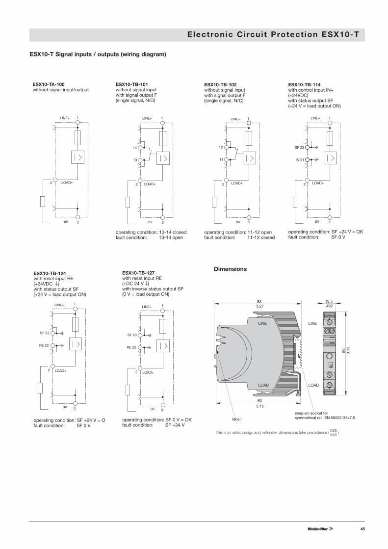
ESX10-T Signal inputs / outputs (wiring diagram)
LINE+ 1
LOAD+2
0V 3
ESX10-TA-100without signal input/output
ESX10-TB-124
operating condition: SF +24 V = Ofault condition: SF 0 V
LINE+ 1
SF 23
IN 21
2 LOAD+
0V 3
ESX10-TB-114with control input IN+(+24VDC)with status output SF(+24 V = load output ON)
operating condition: SF +24 V = OKfault condition: SF 0 V
LINE+ 1
14
13
2 LOAD+
0V 3
ESX10-TB-101without signal inputwith signal output F(single signal, N/O)
operating condition: 13-14 closedfault condition: 13-14 open
LINE+ 1
12
11
2 LOAD+
0V 3
ESX10-TB-102without signal inputwith signal output F(single signal, N/C)
operating condition: 11-12 openfault condition: 11-12 closed
LINE+ 1
SF 23
RE 22
2 LOAD+
0V 3
with reset input RE(+24VDC ↓)with status output SF(+24 V = load output ON)
LINE+ 1
SF 23
RE 22
2 LOAD+
0V 3
ESX10-TB-127with reset input RE(+DC 24 V ↓)with inverse status output SF(0 V = load output ON)
operating condition: SF 0 V = OKfault condition: SF +24 V
Dimensions
12.5
80
80
83
snap-on socket forsymmetrical rail EN 50022-35x7.5label
LINE LINE
LOAD LOAD
3.27 .492
3.15
3.15
This is a metric design and millimeter dimensions take precedence ( mm )inch
46
E lectronic Circuit Protect ion ESX10-T
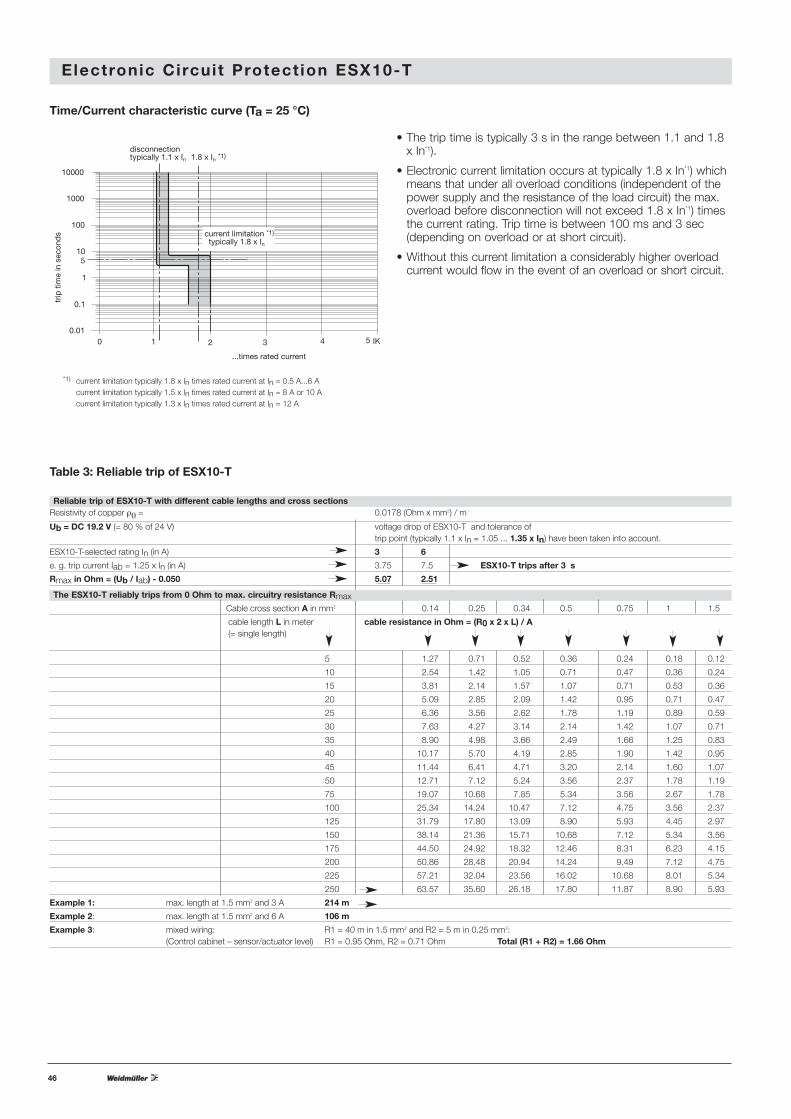
Time/Current characteristic curve (Ta = 25 °C)
• The trip time is typically 3 s in the range between 1.1 and 1.8x In*1).
• Electronic current limitation occurs at typically 1.8 x In*1) whichmeans that under all overload conditions (independent of thepower supply and the resistance of the load circuit) the max.overload before disconnection will not exceed 1.8 x In*1) timesthe current rating. Trip time is between 100 ms and 3 sec(depending on overload or at short circuit).
• Without this current limitation a considerably higher overloadcurrent would flow in the event of an overload or short circuit.
*1) current limitation typically 1.8 x In times rated current at In = 0.5 A...6 Acurrent limitation typically 1.5 x In times rated current at In = 8 A or 10 Acurrent limitation typically 1.3 x In times rated current at In = 12 A
Table 3: Reliable trip of ESX10-T
Reliable trip of ESX10-T with different cable lengths and cross sectionsResistivity of copper ρ0 = 0.0178 (Ohm x mm2) / m
Ub = DC 19.2 V (= 80 % of 24 V) voltage drop of ESX10-T and tolerance of trip point (typically 1.1 x In = 1.05 ... 1.35 x In) have been taken into account.
ESX10-T-selected rating In (in A) 3 6
e. g. trip current Iab = 1.25 x In (in A) 3.75 7.5 ESX10-T trips after 3 s
Rmax in Ohm = (Ub / Iab) - 0.050 5.07 2.51
The ESX10-T reliably trips from 0 Ohm to max. circuitry resistance RmaxCable cross section A in mm2 0.14 0.25 0.34 0.5 0.75 1 1.5
cable length L in meter cable resistance in Ohm = (R0 x 2 x L) / A(= single length)
5 1.27 0.71 0.52 0.36 0.24 0.18 0.12
10 2.54 1.42 1.05 0.71 0.47 0.36 0.24
15 3.81 2.14 1.57 1.07 0.71 0.53 0.36
20 5.09 2.85 2.09 1.42 0.95 0.71 0.47
25 6.36 3.56 2.62 1.78 1.19 0.89 0.59
30 7.63 4.27 3.14 2.14 1.42 1.07 0.71
35 8.90 4.98 3.66 2.49 1.66 1.25 0.83
40 10.17 5.70 4.19 2.85 1.90 1.42 0.95
45 11.44 6.41 4.71 3.20 2.14 1.60 1.07
50 12.71 7.12 5.24 3.56 2.37 1.78 1.19
75 19.07 10.68 7.85 5.34 3.56 2.67 1.78
100 25.34 14.24 10.47 7.12 4.75 3.56 2.37
125 31.79 17.80 13.09 8.90 5.93 4.45 2.97
150 38.14 21.36 15.71 10.68 7.12 5.34 3.56
175 44.50 24.92 18.32 12.46 8.31 6.23 4.15
200 50.86 28.48 20.94 14.24 9.49 7.12 4.75
225 57.21 32.04 23.56 16.02 10.68 8.01 5.34
250 63.57 35.60 26.18 17.80 11.87 8.90 5.93
Example 1: max. length at 1.5 mm2 and 3 A 214 m
Example 2: max. length at 1.5 mm2 and 6 A 106 m
Example 3: mixed wiring: R1 = 40 m in 1.5 mm2 and R2 = 5 m in 0.25 mm2:(Control cabinet – sensor/actuator level) R1 = 0.95 Ohm, R2 = 0.71 Ohm Total (R1 + R2) = 1.66 Ohm
disconnection typically 1.1 x In
current limitation *1)typically 1.8 x In
IK
10000
1000
1 2 4
trip
tim
e in
sec
ond
s
...times rated current
100
10
1
0.1
0.01
3 50
1.8 x In *1)
5
47
E lectronic Circuit Protect ion ESX10-T
5 ESX10-TAwith busbars
5 ESX10-TBwith busbarsand jumpers
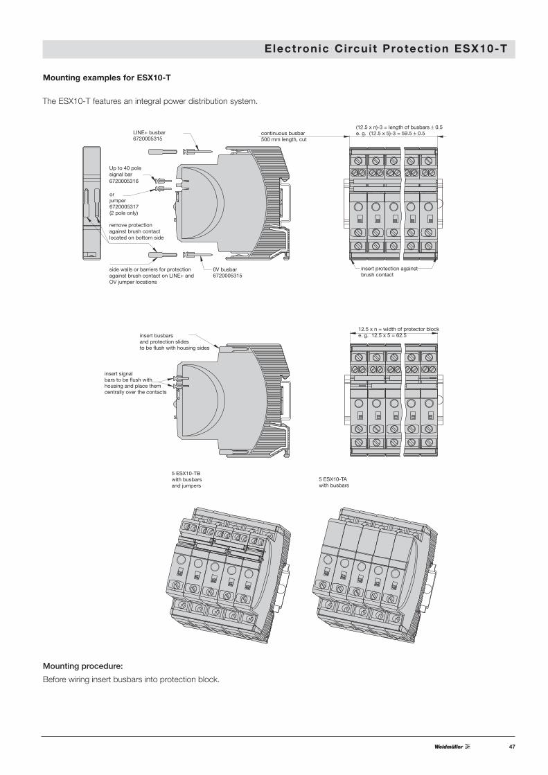
12.5 x n = width of protector blocke. g. 12.5 x 5 = 62.5insert busbars
and protection slidesto be flush with housing sides
insert signalbars to be flush withhousing and place themcentrally over the contacts
LINE+ busbar
remove protection against brush contact located on bottom side
side walls or barriers for protection against brush contact on LINE+ andOV jumper locations
6720005315
0V busbar6720005315
Up to 40 polesignal bar6720005316
orjumper6720005317(2 pole only)
(12.5 x n)-3 = length of busbars ± 0.5e. g. (12.5 x 5)-3 = 59.5 ± 0.5
insert protection againstbrush contact
continuous busbar500 mm length, cut
Mounting examples for ESX10-T
The ESX10-T features an integral power distribution system.
Mounting procedure:
Before wiring insert busbars into protection block.

48
E lectronic Circuit Protect ion ESX10-T
Connection diagrams and application examples ESX10-T
Signal contacts are shown in OFF or fault concition.
power supplyDC 24 V
+24V
0V
- line entry
load
+ -
load
+ -
load+ -
ESX10-TA-100
+ line entry
terminals forbusbars
screwterminals
LINE+ busbar
0 V busbar
1LINE+
1LINE+
1LINE+
ESX10-TA-100 ESX10-TA-100
3 0V 3 0V 3 0V
2 LOAD+ 2 LOAD+ 2 LOAD+
+ line entry+ line entry for the SI
- line entry
power supplyDC 24 V
LINE + busbar
group signallingby means of an LED
jumpers are staggered
0 V busbar
+24V
0V
load load load
+ ++- - -
13
1LINE+
14
ESX10-TB-101
2 LOAD+
3 0V
13
1LINE+
14 13
1LINE+
14
ESX10-TB-101
2 LOAD+
3 0V
ESX10-TB-101
2 LOAD+
3 0V
power supplyDC 24 V
+24V
0 V
+ line entry
+ line entryfor the SI
- line entry
11
1LINE+
12 11
1LINE+
12 11
1LINE+
12
2 LOAD+
ESX10-TB-102
3 0V
2 LOAD+
ESX10-TB-102
3 0V
2 LOAD+
ESX10-TB-102
3 0V
load
+ -
load
+ -
load
+ -
signal busbar forcommon line entry
0 V busbar
LINE+ busbar
single signalling per wayby means of an LED
power supplyDC 24 V
+24V
0V
+ line entry
- line entry
2 LOAD+
ESX10-TB-124
3 0V
2 LOAD+
ESX10-TB-124
3 0V
2 LOAD+
ESX10-TB-124
3 0V
load
+ -
load
+ -
load
+ -
signal busbar forcommon reset
0 V busbar
LINE+ busbar
single signalling per wayby means of an LED
22
1LINE+
RE SF23 22
1LINE+
RE SF23 22
1LINE+
RE SF23
resetbutton
ESX10-TA-100 ESX10-TB-101
group signaling (series connection)
ESX10-TB-102
Single signaling with common line entry
ESX10-TB-124
Single signaling with common reset
49
E lectronic Circuit Protect ion ESX10-T
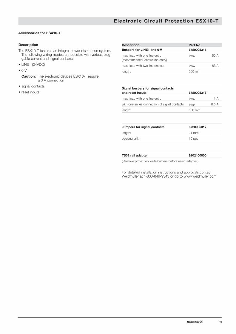
Accessories for ESX10-T
Description
The ESX10-T features an integral power distribution system.The following wiring modes are possible with various plug-gable current and signal busbars:
• LINE +(24VDC)
• 0 V
Caution: The electronic devices ESX10-T require a 0 V connection
• signal contacts
• reset inputs
Description Part No.Busbars for LINE+ and 0 V 6720005315
max. load with one line entry Imax 50 A(recommended: centre line entry)
max. load with two line entries Imax 63 A
length: 500 mm
Signal busbars for signal contactsand reset inputs 6720005316
max. load with one line entry Imax 1 A
with one series connection of signal contacts Imax 0.5 A
length: 500 mm
Jumpers for signal contacts 6720005317
length: 21 mm
packing unit: 10 pcs
TS32 rail adapter 9102100000
(Remove protection walls/barriers before using adapter.)
For detailed installation instructions and approvals contactWeidmuller at 1-800-849-9343 or go to www.weidmuller.com
50
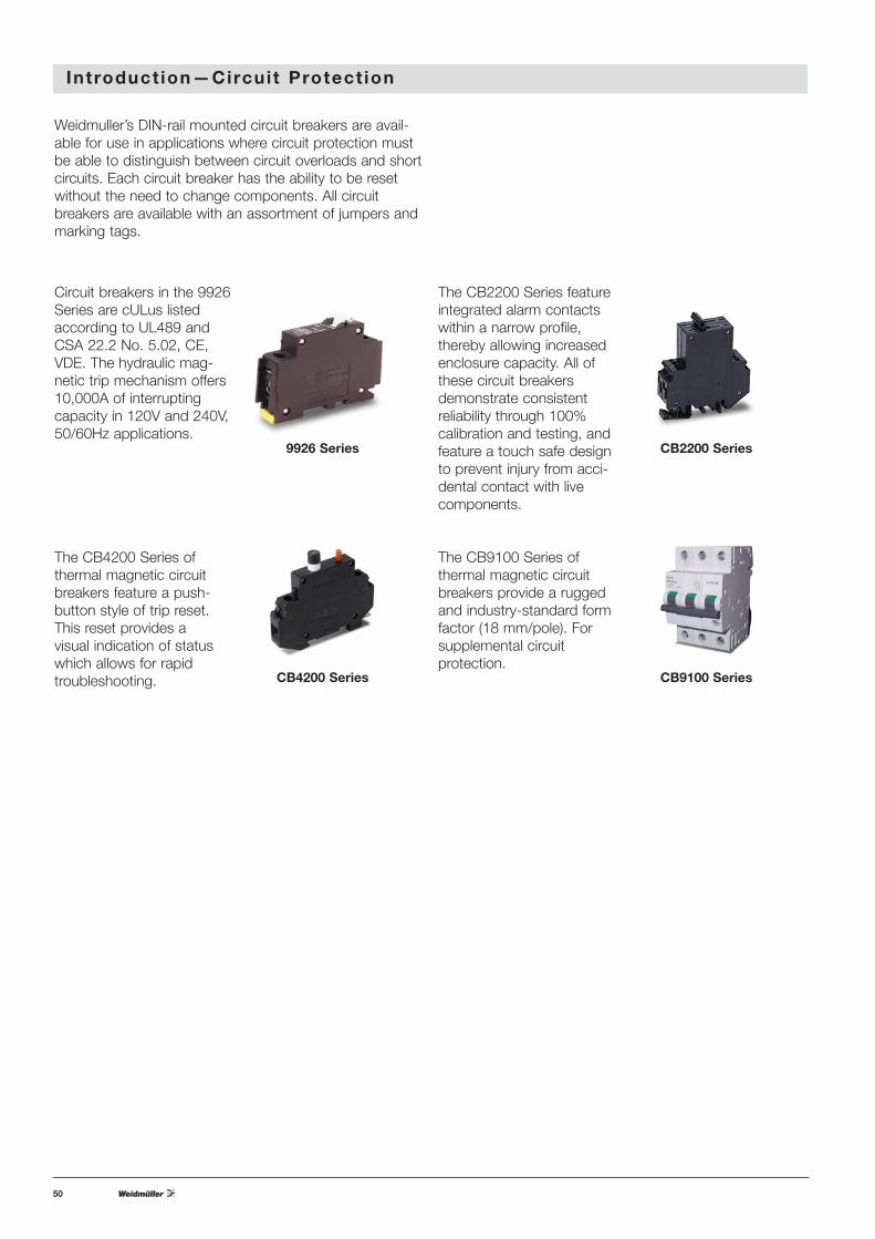
Introduct ion—Circuit Protect ion
Circuit breakers in the 9926Series are cULus listedaccording to UL489 andCSA 22.2 No. 5.02, CE,VDE. The hydraulic mag-netic trip mechanism offers10,000A of interruptingcapacity in 120V and 240V,50/60Hz applications.
9926 Series
CB4200 Series
CB2200 Series
CB9100 Series
The CB2200 Series featureintegrated alarm contactswithin a narrow profile,thereby allowing increasedenclosure capacity. All ofthese circuit breakersdemonstrate consistentreliability through 100% calibration and testing, andfeature a touch safe designto prevent injury from acci-dental contact with livecomponents.
The CB9100 Series of thermal magnetic circuitbreakers provide a ruggedand industry-standard formfactor (18 mm/pole). Forsupplemental circuit protection.
Weidmuller’s DIN-rail mounted circuit breakers are avail-able for use in applications where circuit protection mustbe able to distinguish between circuit overloads and shortcircuits. Each circuit breaker has the ability to be resetwithout the need to change components. All circuitbreakers are available with an assortment of jumpers andmarking tags.
The CB4200 Series of thermal magnetic circuitbreakers feature a push-button style of trip reset.This reset provides a visual indication of statuswhich allows for rapid troubleshooting.
51
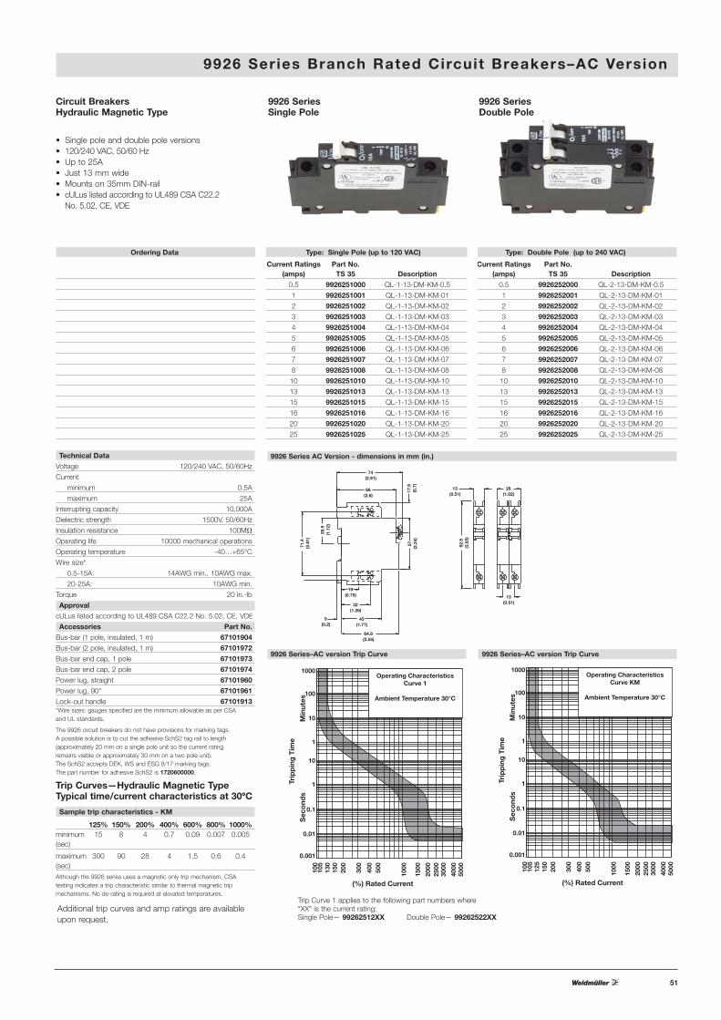
9926 Ser ies Branch Rated Circuit Breakers–AC Version
Circuit BreakersHydraulic Magnetic Type
• Single pole and double pole versions• 120/240 VAC, 50/60 Hz• Up to 25A• Just 13 mm wide• Mounts on 35mm DIN-rail• cULus listed according to UL489 CSA C22.2
No. 5.02, CE, VDE
1000
Trip
pin
g T
ime
Sec
ond
sM
inut
es
100
10
1
10
1
0.1
0.01
0.001
100
105
125
150
200
300
400
500
1000
1500
2000
2500
3000
4000
5000
(%) Rated Current
Operating CharacteristicsCurve KM
Ambient Temperature 30°C
Trip Curves—Hydraulic Magnetic TypeTypical time/current characteristics at 30ºC
9926 Series–AC version Trip Curve
Ordering Data Type: Single Pole (up to 120 VAC) Type: Double Pole (up to 240 VAC)
Current Ratings Part No. Current Ratings Part No.(amps) TS 35 Description (amps) TS 35 Description
0.5 9926251000 QL-1-13-DM-KM-0.5 0.5 9926252000 QL-2-13-DM-KM-0.5
1 9926251001 QL-1-13-DM-KM-01 1 9926252001 QL-2-13-DM-KM-01
2 9926251002 QL-1-13-DM-KM-02 2 9926252002 QL-2-13-DM-KM-02
3 9926251003 QL-1-13-DM-KM-03 3 9926252003 QL-2-13-DM-KM-03
4 9926251004 QL-1-13-DM-KM-04 4 9926252004 QL-2-13-DM-KM-04
5 9926251005 QL-1-13-DM-KM-05 5 9926252005 QL-2-13-DM-KM-05
6 9926251006 QL-1-13-DM-KM-06 6 9926252006 QL-2-13-DM-KM-06
7 9926251007 QL-1-13-DM-KM-07 7 9926252007 QL-2-13-DM-KM-07
8 9926251008 QL-1-13-DM-KM-08 8 9926252008 QL-2-13-DM-KM-08
10 9926251010 QL-1-13-DM-KM-10 10 9926252010 QL-2-13-DM-KM-10
13 9926251013 QL-1-13-DM-KM-13 13 9926252013 QL-2-13-DM-KM-13
15 9926251015 QL-1-13-DM-KM-15 15 9926252015 QL-2-13-DM-KM-15
16 9926251016 QL-1-13-DM-KM-16 16 9926252016 QL-2-13-DM-KM-16
20 9926251020 QL-1-13-DM-KM-20 20 9926252020 QL-2-13-DM-KM-20
25 9926251025 QL-1-13-DM-KM-25 25 9926252025 QL-2-13-DM-KM-25
9926 SeriesSingle Pole
9926 SeriesDouble Pole
Sample trip characteristics - KM
125% 150% 200% 400% 600% 800% 1000%minimum 15 8 4 0.7 0.09 0.007 0.005(sec)
maximum 300 90 28 4 1.5 0.6 0.4(sec)Although the 9926 series uses a magnetic only trip mechanism, CSA testing indicates a trip characteristic similar to thermal magnetic trip mechanisms. No de-rating is required at elevated temperatures.
Technical Data
Voltage 120/240 VAC, 50/60Hz
Current
minimum 0.5A
maximum 25A
Interrupting capacity 10,000A
Dielectric strength 1500V, 50/60Hz
Insulation resistance 100MM
Operating life 10000 mechanical operations
Operating temperature -40…+65°C
Wire size*
0.5-15A: 14AWG min., 10AWG max.
20-25A: 10AWG min.
Torque 20 in.-lb
Approval
cULus listed according to UL489 CSA C22.2 No. 5.02, CE, VDE
Accessories Part No.
Bus-bar (1 pole, insulated, 1 m) 67101904
Bus-bar (2 pole, insulated, 1 m) 67101972
Bus-bar end cap, 1 pole 67101973
Bus-bar end cap, 2 pole 67101974
Power lug, straight 67101960
Power lug, 90° 67101961
Lock-out handle 67101913*Wire sizes: gauges specified are the minimum allowable as per CSA and UL standards.
The 9926 circuit breakers do not have provisions for marking tags. A possible solution is to cut the adhesive SchS2 tag rail to length (approximately 20 mm on a single pole unit so the current rating remains visible or approximately 30 mm on a two pole unit).The SchS2 accepts DEK, WS and ESG 8/17 marking tags.The part number for adhesive SchS2 is 1720600000.
19(0.75)
74(2.91)
66(2.6)
17.9
(0.7
)
71.4
(2.8
1)
28.5
(1.1
2)
5(0.2)
32(1.26)
45(1.77)
64.8(2.55)
57(2
.24)
13(0.51)
92.8
(3.6
5)
26(1.02)
13(0.51)
9926 Series AC Version - dimensions in mm (in.)
Additional trip curves and amp ratings are availableupon request.
1000
Trip
pin
g T
ime
Sec
ond
sM
inut
es
100
10
1
10
1
0.1
0.01
0.001
100
105
130
150
200
300
400
500
1000
1500
2000
2500
3000
4000
5000
(%) Rated Current
Operating CharacteristicsCurve 1
Ambient Temperature 30°C
9926 Series–AC version Trip Curve
Trip Curve 1 applies to the following part numbers where "XX" is the current rating: Single Pole— 99262512XX Double Pole— 99262522XX

52
9926 Ser ies Branch Rated Circuit Breakers–AC Version with Contacts
Type: Double Pole Trip (up to 240 VAC)
Current Ratings(amps) Part No. Description
1 9926272001 QL-T-2-13-DM-KM-1
2 9926272002 QL-T-2-13-DM-KM-2
5 9926272005 QL-T-2-13-DM-KM-5
10 9926272010 QL-T-2-13-DM-KM-10
15 9926272015 QL-T-2-13-DM-KM-15
20 9926272020 QL-T-2-13-DM-KM-20
25 9926272025 QL-T-2-13-DM-KM-25
Type: Double Pole Combo (up to 240 VAC)
Current Ratings(amps) Part No. Description
1 9926282001 QL-AT-2-13-DM-KM-1
2 9926282002 QL-AT-2-13-DM-KM-2
5 9926282005 QL-AT-2-13-DM-KM-5
10 9926282010 QL-AT-2-13-DM-KM-10
15 9926282015 QL-AT-2-13-DM-KM-15
20 9926282020 QL-AT-2-13-DM-KM-20
25 9926282025 QL-AT-2-13-DM-KM-25
1000
Trip
pin
g T
ime
Sec
ond
sM
inut
es
100
10
1
10
1
0.1
0.01
0.001
100
105
125
150
200
300
400
500
1000
1500
2000
2500
3000
4000
5000
(%) Rated Current
Operating CharacteristicsCurve KM
Ambient Temperature 30°C
9926 Series–AC version Trip Curve
Circuit Breakers withAuxiliary switch, Trip alarm,Combination of both
• AC voltages (120/240V)
• Single and double pole versions
• cULus listed according to UL489 and C22.2 No. 5.02, CE, VDE
• Factory fitted auxiliary or trip alarm
• Compact 6.5mm width
• Attached to right hand side of circuit breaker
Technical Data
Voltage 120/240 VAC, 50/60Hz
Current
minimum 0.5A
maximum 25A
Interrupting capacity 10,000A
Dielectric strength 1500V, 50/60Hz
Insulation resistance 100MM
Operating life 10000 mechanical operations
Operating temperature -40…+65°C
Wire size*
0.5-15A: 14AWG min., 10AWG max.
20-25A: 10AWG min.
Torque 20 in.-lb
Approval
cULus listed according to UL489 and C22.2
No. 5.02, CE, VDE
9926 SeriesDouble Pole Trip(Alarm Contact)
9926 SeriesDouble Pole Combination(Auxiliary & Alarm Contact)†
Trip Curves—HydraulicMagnetic Type Typical time/current characteristics at 30ºC
Additional trip curves and amp ratings are available upon request.
Type: Double Pole Aux (up to 240 VAC)
Current Ratings(amps) Part No. Description
1 9926262001 QL-A-2-13-DM-KM-1
2 9926262002 QL-A-2-13-DM-KM-2
5 9926262005 QL-A-2-13-DM-KM-5
10 9926262010 QL-A-2-13-DM-KM-10
15 9926262015 QL-A-2-13-DM-KM-15
20 9926262020 QL-A-2-13-DM-KM-20
25 9926262025 QL-A-2-13-DM-KM-25
9926 SeriesDouble Polew/ Auxiliary Contact†
Type: Single Pole Aux (up to 120 VAC)
Current Ratings(amps) Part No. Description
1 9926261001 QL-A-1-13-DM-KM-1
2 9926261002 QL-A-1-13-DM-KM-2
5 9926261005 QL-A-1-13-DM-KM-5
10 9926261010 QL-A-1-13-DM-KM-10
15 9926261015 QL-A-1-13-DM-KM-15
20 9926261020 QL-A-1-13-DM-KM-20
25 9926261025 QL-A-1-13-DM-KM-25
9926 SeriesSingle Pole w/ Auxiliary Contact†
Type: Single Pole Trip (up to 120 VAC)
Current Ratings(amps) Part No. Description
1 9926271001 QL-T-1-13-DM-KM-1
2 9926271002 QL-T-1-13-DM-KM-2
5 9926271005 QL-T-1-13-DM-KM-5
10 9926271010 QL-T-1-13-DM-KM-10
15 9926271015 QL-T-1-13-DM-KM-15
20 9926271020 QL-T-1-13-DM-KM-20
25 9926271025 QL-T-1-13-DM-KM-25
9926 SeriesSingle Pole Trip(Alarm Contact)
Type: Single Pole Combo (up to 120 VAC)
Current Ratings(amps) Part No. Description
1 9926281001 QL-AT-1-13-DM-KM-1
2 9926281002 QL-AT-1-13-DM-KM-2
5 9926281005 QL-AT-1-13-DM-KM-5
10 9926281010 QL-AT-1-13-DM-KM-10
15 9926281015 QL-AT-1-13-DM-KM-15
20 9926281020 QL-AT-1-13-DM-KM-20
25 9926281025 QL-AT-1-13-DM-KM-25
9926 SeriesSingle Pole Combination(Auxiliary & Alarm Contact)†
Dual Mount Dimensions in mm (in.)
57.0
(2.2
4)
26.2(1.03)
31.3(1.23)
21.1(0.83)
21.3(0.84) 32.9
(1.3)
10.7(0.42)
(N/O
)16
(N/C
)18
(C)1
5
11(C
)
12(N
/C)
14(N
/O)
TRIP ALARM Q. CONNECTORS
2(0
.08)
0.5
(0.0
2)
5.5(0.22)
AUX SWITCH Q. CONNECTORS
2.8
(0.1
1)
0.5
(0.0
2)
7(0.28)
†UL 489 listed(5A, 250 VAC; 0.5A, 80 VDC Auxiliary; 0.5A, 125 VDC Trip Alarm)
IEC 60947-5-1 Approved(5A, 250 VAC; 0.5A, 110 VDC Auxiliary; 0.5A, 125 VDC Trip Alarm)
*Wire sizes: gauges specified are the minimum allowable as per CSA and UL standards.
The 9926 circuit breakers do not have provisions formarking tags. A possible solution is to cut the adhesiveSchS2 tag rail to length (approximately 20 mm on a sin-gle pole unit so the current rating remains visible orapproximately 30 mm on a two pole unit). The SchS2accepts DEK, WS and ESG 8/17 marking tags. Thepart number for adhesive SchS2 is 1720600000.

53
Accessories
Type Part No.
Bus-bar (1 pole, insulated 1m) 67101904
Bus bar end cap, 1 pole 67101973
Power lug, straight 67101960
Power lug, 90° 67101961
Lock-out handle 67101913
9926 Ser ies Branch Rated Circuit Breakers–DC Version
1000
Trip
pin
g T
ime
Sec
ond
sM
inut
es
100
10
1
10
1
0.1
0.01
0.001
100
130
105
150
200
300
400
500
1000
1500
2000
2500
3000
4000
5000
(%) Rated Current
Operating CharacteristicsCurve U2 DC
(4% Ripple Factor)
Ambient Temperature 30°C
9926 Series–DC version Trip Curve
Circuit BreakersHydraulic Magnetic Type
• Single pole versions only• U2 trip curve for general purpose
applications• 80 and 125 VDC• Up to 60A• Just 13 mm wide• Mounts on 35mm DIN-rail• UL 489A listed• VDE
9926 SeriesSingle Pole(80 VDC)
Ordering Data Type: Single Pole (80 VDC)
Current Ratings(amps) Part No. Description
0.5 9926251900 QY-1-13-DM-U2-0.5
1 9926251901 QY-1-13-DM-U2-01
2 9926251902 QY-1-13-DM-U2-02
3 9926251903 QY-1-13-DM-U2-03
4 9926251904 QY-1-13-DM-U2-04
5 9926251905 QY-1-13-DM-U2-05
10 9926251910 QY-1-13-DM-U2-10
15 9926251915 QY-1-13-DM-U2-15
20 9926251920 QY-1-13-DM-U2-20
25 9926251925 QY-1-13-DM-U2-25
30 9926251930 QY-1-13-DM-U2-30
35 9926251935 QY-1-13-DM-U2-35
40 9926251940 QY-1-13-DM-U2-40
45 9926251945 QY-1-13-DM-U2-45
50 9926251950 QY-1-13-DM-U2-50
60 9926251960 QY-1-13-DM-U2-60
Technical Data
Voltage 80,125 VDC
Current
minimum 0.5 A
maximum 60 A
Interrupting capacity 10,000 A
Dielectric strength 1500 V, 50/60 Hz
Insulation resistance 100 MMOperating life 10000
mechanical operations
Operating temperature -40…+65°CWire size*
1-15A: 14 AWG min., 10 AWG max.
20-25A: 10 AWG min.
Torque 20 in.-lb
Approval
UL 489A Listed, CE, VDE
*Wire sizes: gauges specified are the minimum allow-able as per CSA and UL standards.
The 9926 circuit breakers do not have provisions formarking tags. A possible solution is to cut the adhesiveSchS2 tag rail to length (approximately 20 mm on a sin-gle pole unit so the current rating remains visible orapproximately 30 mm on a two pole unit). The SchS2accepts DEK, WS and ESG 8/17 marking tags. Thepart number for adhesive SchS2 is 1720600000.
19(0.75)
74(2.91)
66(2.6)
17.9
(0.7
)
71.4
(2.8
1)
28.5
(1.1
2)
5(0.2)
32(1.26)
45(1.77)
64.8(2.55)
57(2
.24)
13(0.51)
92.8
(3.6
5)
9926 SeriesSingle Pole(125 VDC)
Type: Single Pole (125 VDC)
Current Ratings(amps) Part No. Description
1 9926251801 QY-1-13-DM-U2-01-B1
2 9926251802 QY-1-13-DM-U2-02-B1
3 9926251803 QY-1-13-DM-U2-03-B1
4 9926251804 QY-1-13-DM-U2-04-B1
5 9926251805 QY-1-13-DM-U2-05-B1
10 9926251810 QY-1-13-DM-U2-10-B1
15 9926251815 QY-1-13-DM-U2-15-B1
20 9926251820 QY-1-13-DM-U2-20-B1
25 9926251825 QY-1-13-DM-U2-25-B1
30 9926251830 QY-1-13-DM-U2-30-B1
35 9926251835 QY-1-13-DM-U2-35-B1
40 9926251840 QY-1-13-DM-U2-40-B1
45 9926251845 QY-1-13-DM-U2-45-B1
50 9926251850 QY-1-13-DM-U2-50-B1
60 9926251860 QY-1-13-DM-U2-60-B1
Dimensions in mm (in.)
Trip Curves—HydraulicMagnetic Type Typical time/current characteristics at 30ºC
Additional trip curves and amp ratings are available upon request.
54
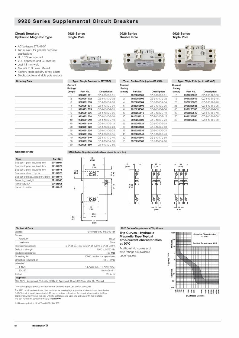
Type: Single Pole (up to 277 VAC) Type: Double Pole (up to 480 VAC) Type: Triple Pole (up to 480 VAC)
Current Current CurrentRatings Rating Rating(amps) Part No. Description (amps) Part No. Description (amps) Part No. Description
1 9926251501 QZ-1-13-D-2-01 1 9926252501 QZ-2-13-D-2-01 10 9926253510 QZ-3-13-D-2-10
2 9926251502 QZ-1-13-D-2-02 2 9926252502 QZ-2-13-D-2-02 15 9926253515 QZ-3-13-D-2-15
3 9926251503 QZ-1-13-D-2-03 4 9926252504 QZ-2-13-D-2-04 20 9926253520 QZ-3-13-D-2-20
4 9926251504 QZ-1-13-D-2-04 5 9926252505 QZ-2-13-D-2-05 25 9926253525 QZ-3-13-D-2-25
5 9926251505 QZ-1-13-D-2-05 6 9926252506 QZ-2-13-D-2-06 30 9926253530 QZ-3-13-D-2-30
6 9926251506 QZ-1-13-D-2-06 10 9926252510 QZ-2-13-D-2-10 40 9926253540 QZ-3-13-D-2-40
8 9926251508 QZ-1-13-D-2-08 15 9926252515 QZ-2-13-D-2-15 50 9926253550 QZ-3-13-D-2-50
10 9926251510 QZ-1-13-D-2-10 20 9926252520 QZ-2-13-D-2-20 60 9926253560 QZ-3-13-D-2-60
15 9926251515 QZ-1-13-D-2-15 25 9926252525 QZ-2-13-D-2-25
20 9926251520 QZ-1-13-D-2-20 30 9926252530 QZ-2-13-D-2-30
25 9926251525 QZ-1-13-D-2-25 35 9926252535 QZ-2-13-D-2-35
35 9926251535 QZ-1-13-D-2-35 40 9926252540 QZ-2-13-D-2-40
40 9926251540 QZ-1-13-D-2-40 50 9926252550 QZ-2-13-D-2-50
50 9926251550 QZ-1-13-D-2-50 60 9926252560 QZ-2-13-D-2-60
60 9926251560 QZ-1-13-D-2-60
9926 Ser ies Supplemental Circuit Breakers
Circuit BreakersHydraulic Magnetic Type
• AC Voltages 277/480V• Trip curve 2 for general purpose
applications• UL 1077 recognized• VDE approved and CE marked • Just 13 mm wide• Mounts to 35 mm DIN-rail• Factory fitted auxiliary or trip alarm• Single, double and triple pole versions
1000
Trip
pin
g T
ime
Sec
ond
sM
inut
es
100
10
1
10
1
0.1
0.01
0.001
100
130
105
150
200
300
400
500
1000
1500
2000
2500
3000
4000
5000
(%) Rated Current
Operating CharacteristicsCurve 2
Ambient Temperature 30°C
9926 Series–Supplemental Trip Curve
9926 SeriesTriple Pole
9926 SeriesDouble Pole
9926 SeriesSingle Pole
Accessories
Type Part No.Bus bar (1 pole, insulated 1m) 67101904Bus bar (2 pole, insulated 1m) 67101972Bus bar (3 pole, insulated 1m) 67101971Bus bar end cap, 1 pole 67101973Bus bar end cap, 2 pole or 3 pole 67101974Power lug, straight 67101960Power lug, 90° 67101961Lock-out handle 67101913
Ordering Data
Technical DataVoltage 277/480 VAC @ 50/60 Hz
Current
minimum 0.5 A
maximum 60 A
Interrupting capacity 5 kA @ 277/480 V, 5 kA @ 120 V, 5 kA @ 240 V
Dielectric strength 1500 V, 50/60 Hz
Insulation resistance 100 MM
Operating life 10000 mechanical operations
Operating temperature -40…+65°C
Wire size*
1-15A: 14 AWG min., 10 AWG max.
20-25A: 10 AWG min.
Torque 20 in.-lb
Approval†UL 1077 Recognized, VDE (EN 60947-2) Approved, CSA C22.2 No. 235, CE Marked
*Wire sizes: gauges specified are the minimum allowable as per CSA and UL standards.
The 9926 circuit breakers do not have provisions for marking tags. A possible solution is to cut the adhesive SchS2 tag rail to length (approximately 20 mm on a single pole unit so the current rating remains visible or approximately 30 mm on a two pole unit).The SchS2 accepts DEK, WS and ESG 8/17 marking tags. The part number for adhesive SchS2 is 1720600000.
†cURus recognized to UL1077 and C22.2 No. 235
Additional trip curves and amp ratings are available upon request.
Trip Curves—HydraulicMagnetic Type Typical time/current characteristics at 30ºC
9926 Series Supplemental – dimensions in mm (in.)
65(2.56)
60(2.36)
22.5
(0.8
6)
25.9
(0.9
4)45
(1.7
7)
44(1.73)
63.8(2.51)
73(2.87)
5.0(0.2)
13(0.51)
92.8
(3.6
5)
26(1.02)
13(0.51)
13(0.51)
39(1.54)

55
1000
Trip
pin
g T
ime
Sec
ond
sM
inut
es
100
10
1
10
1
0.1
0.01
0.001
100
130
105
150
200
300
400
500
1000
1500
2000
2500
3000
4000
5000
(%) Rated Current
Operating CharacteristicsCurve 2
Ambient Temperature 30°C
†cURus recognized to UL1077 and C22.2 No. 235
Trip Curves—HydraulicMagnetic Type Typical time/current characteristics at 30ºC
Type: Double Pole Trip (up to 480 VAC)
Current Ratings(amps) Part No. Description
1 9926272501 QZ-T-2-13-D-2-01
2 9926272502 QZ-T-2-13-D-2-02
5 9926272505 QZ-T-2-13-D-2-05
10 9926272510 QZ-T-2-13-D-2-10
15 9926272515 QZ-T-2-13-D-2-15
20 9926272520 QZ-T-2-13-D-2-20
25 9926272525 QZ-T-2-13-D-2-25
Type: Double Pole Combo (up to 480 VAC)
Current Ratings(amps) Part No. Description
1 9926282501 QZ-AT-2-13-D-2-01
2 9926282502 QZ-AT-2-13-D-2-02
5 9926282505 QZ-AT-2-13-D-2-05
10 9926282510 QZ-AT-2-13-D-2-10
15 9926282515 QZ-AT-2-13-D-2-15
20 9926282520 QZ-AT-2-13-D-2-20
25 9926282525 QZ-AT-2-13-D-2-25
9926 SeriesDouble Pole Trip(Alarm Contact)
9926 SeriesDouble Pole Combination(Auxiliary & Alarm Contact)‡
Type: Double Pole Aux (up to 480 VAC)
Current Ratings(amps) Part No. Description
1 9926262501 QZ-A-2-13-D-2-01
2 9926262502 QZ-A-2-13-D-2-02
5 9926262505 QZ-A-2-13-D-2-05
10 9926262510 QZ-A-2-13-D-2-10
15 9926262515 QZ-A-2-13-D-2-15
20 9926262520 QZ-A-2-13-D-2-20
25 9926262525 QZ-A-2-13-D-2-25
9926 SeriesDouble Pole w/ Auxiliary Contact‡
Type: Single Pole Aux (up to 277 VAC)
Current Ratings(amps) Part No. Description
1 9926261501 QZ-A-1-13-D-2-01
2 9926261502 QZ-A-1-13-D-2-02
5 9926261505 QZ-A-1-13-D-2-05
10 9926261510 QZ-A-1-13-D-2-10
15 9926261515 QZ-A-1-13-D-2-15
20 9926261520 QZ-A-1-13-D-2-20
25 9926261525 QZ-A-1-13-D-2-25
9926 SeriesSingle Pole w/ Auxiliary Contact‡
Type: Single Pole Trip (up to 277 VAC)
Current Ratings(amps) Part No. Description
1 9926271501 QZ-T-1-13-D-2-01
2 9926271502 QZ-T-1-13-D-2-02
5 9926271505 QZ-T-1-13-D-2-05
10 9926271510 QZ-T-1-13-D-2-10
15 9926271515 QZ-T-1-13-D-2-15
20 9926271520 QZ-T-1-13-D-2-20
25 9926271525 QZ-T-1-13-D-2-25
9926 SeriesSingle Pole Trip(Alarm Contact)
Type: Single Pole Combo (up to 277 VAC)
Current Ratings(amps) Part No. Description
1 9926281501 QZ-AT-1-13-D-2-01
2 9926281502 QZ-AT-1-13-D-2-02
5 9926281505 QZ-AT-1-13-D-2-05
10 9926281510 QZ-AT-1-13-D-2-10
15 9926281515 QZ-AT-1-13-D-2-15
20 9926281520 QZ-AT-1-13-D-2-20
25 9926281525 QZ-AT-1-13-D-2-25
9926 SeriesSingle Pole Combination(Auxiliary & Alarm Contact)‡
9926 Ser ies Supplemental Circuit Breakers with Contacts
Type: Triple Pole Trip (up to 480 VAC)
Current Ratings(amps) Part No. Description
1 9926273501 QZ-T-3-13-D-2-01
2 9926273502 QZ-T-3-13-D-2-02
5 9926273505 QZ-T-3-13-D-2-05
10 9926273510 QZ-T-3-13-D-2-10
15 9926273515 QZ-T-3-13-D-2-15
20 9926273520 QZ-T-3-13-D-2-20
25 9926273525 QZ-T-3-13-D-2-25
Type: Triple Pole Combo (up to 480 VAC)
Current Ratings(amps) Part No. Description
1 9926283501 QZ-AT-3-13-D-2-01
2 9926283502 QZ-AT-3-13-D-2-02
5 9926283505 QZ-AT-3-13-D-2-05
10 9926283510 QZ-AT-3-13-D-2-10
15 9926283515 QZ-AT-3-13-D-2-15
20 9926283520 QZ-AT-3-13-D-2-20
25 9926283525 QZ-AT-3-13-D-2-25
9926 SeriesTriple Pole Trip ( Alarm Contact)
9926 SeriesTriple Pole Combination(Auxiliary & Alarm Contact)‡
Type: Triple Pole Aux (up to 480 VAC)
Current Ratings(amps) Part No. Description
1 9926263501 QZ-A-3-13-D-2-01
2 9926263502 QZ-A-3-13-D-2-02
5 9926263505 QZ-A-3-13-D-2-05
10 9926263510 QZ-A-3-13-D-2-10
15 9926263515 QZ-A-3-13-D-2-15
20 9926263520 QZ-A-3-13-D-2-20
25 9926263525 QZ-A-3-13-D-2-25
9926 SeriesTriple Pole w/ Auxiliary Contact‡
Circuit BreakersAuxiliary switch, Trip alarm,Combination of both
• AC Voltages 277/480V• Trip curve 2 for general purpose
applications• UL 1077 recognized• VDE approved and CE marked• Just 13 mm wide• Mounts to 35 mm DIN-rail• Factory fitted auxiliary or trip alarm• Single, double and triple pole versions
9926 Series–Supplemental Trip Curve
Technical Data
Voltage 277/480 VAC @ 50/60 Hz
Current
minimum 0.5 A
maximum 60 A
Interrupting capacity 5 kA @ 277/480 V,
5 kA @ 120 V, 5 kA @ 240 V
Dielectric strength 1500 V, 50/60 Hz
Insulation resistance 100 MM
Operating life 10000 mechanical operations
Operating temperature -40…+65°C
Wire size*
1-15A: 14 AWG min., 10 AWG max.
20-25A: 10 AWG min.
Torque 20 in.-lb
Approval†UL 1077 Recognized, VDE (EN 60947-2)
Approved, CSA C22.2 No. 235, CE Marked‡UL 489 listed(5A, 250 VAC; 0.5A, 80 VDC Auxiliary; 0.5A, 125 VDC Trip Alarm)
IEC 60947-5-1 Approved(5A, 250 VAC; 0.5A, 110 VDC Auxiliary; 0.5A, 125 VDC Trip Alarm)
*Wire sizes: gauges specified are the minimum allow-able as per CSA and UL standards.
The 9926 circuit breakers do not have provisions formarking tags. A possible solution is to cut the adhesiveSchS2 tag rail to length (approximately 20 mm on asingle pole unit so the current rating remains visible orapproximately 30 mm on a two pole unit). The SchS2accepts DEK, WS and ESG 8/17 marking tags.The partnumber for adhesive SchS2 is 1720600000.
56
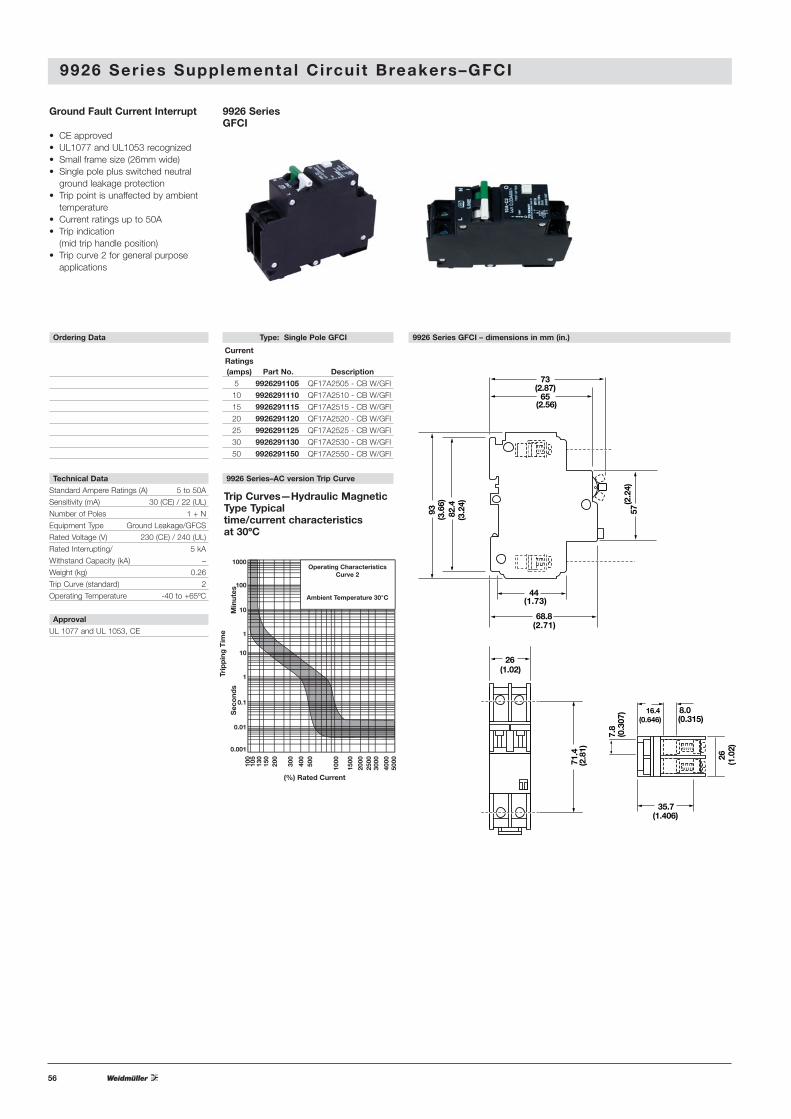
9926 Ser ies Supplemental Circuit Breakers–GFCI
Trip Curves—Hydraulic MagneticType Typical time/current characteristics at 30ºC
Type: Single Pole GFCI
Current Ratings(amps) Part No. Description
5 9926291105 QF17A2505 - CB W/GFI
10 9926291110 QF17A2510 - CB W/GFI
15 9926291115 QF17A2515 - CB W/GFI
20 9926291120 QF17A2520 - CB W/GFI
25 9926291125 QF17A2525 - CB W/GFI
30 9926291130 QF17A2530 - CB W/GFI
50 9926291150 QF17A2550 - CB W/GFI
9926 SeriesGFCI
Ground Fault Current Interrupt
• CE approved• UL1077 and UL1053 recognized• Small frame size (26mm wide)• Single pole plus switched neutral
ground leakage protection• Trip point is unaffected by ambient
temperature• Current ratings up to 50A• Trip indication
(mid trip handle position) • Trip curve 2 for general purpose
applications
Ordering Data
9926 Series–AC version Trip Curve
9926 Series GFCI – dimensions in mm (in.)
Technical Data
Standard Ampere Ratings (A) 5 to 50A
Sensitivity (mA) 30 (CE) / 22 (UL)
Number of Poles 1 + N
Equipment Type Ground Leakage/GFCS
Rated Voltage (V) 230 (CE) / 240 (UL)
Rated Interrupting/ 5 kA
Withstand Capacity (kA) –
Weight (kg) 0.26
Trip Curve (standard) 2
Operating Temperature -40 to +65ºC
Approval
UL 1077 and UL 1053, CE
1000
Trip
pin
g T
ime
Sec
ond
sM
inut
es
100
10
1
10
1
0.1
0.01
0.001
100
130
105
150
200
300
400
500
1000
1500
2000
2500
3000
4000
5000
(%) Rated Current
Operating CharacteristicsCurve 2
Ambient Temperature 30°C
82.4
(3.2
4)
93(3
.66)
73(2.87)
65(2.56)
26(1.02)
26(1
.02)
16.4(0.646)
35.7(1.406)
8.0(0.315)
44(1.73)
68.8(2.71)
71.4
(2.8
1)
7.8
(0.3
07)
57(2
.24)
57
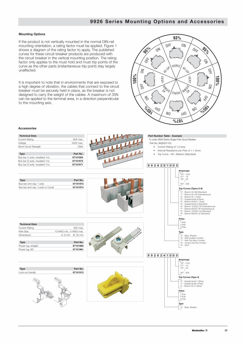
9 9 2 6 2 5 1 0 0 0
Amperage
"00" - 0.5A"01" - 1A"02" - 2A
"60" - 60A
Type
"5" - Base Breaker"6" - With Auxiliary Contact"7" - With Trip Alarm Contact"8" - Combo Aux/Trip Contact"9" - GFCI
Poles
1 Pole2 Pole3 Pole
Trip Curves (Types 5-9)
"0" - Branch AC KM (Standard)"1" - Branch AC OP (Instantaneous)"2" - Branch AC 1 (Fast)"3" - Supplemental 9 (Slow)"4" - Branch 80VDC 1 (Fast)"5" - Supplemental 2 (Standard)"6" - Branch 125VDC OP (Instantaneous)"7" - Branch 80VDC OP (Instantaneous)"8" - Branch 125VDC U2 (Standard)"9" - Branch 80VDC U2 (Standard)
/
Part Number Table - Example
To order 9926 Series Single Pole Circuit Breaker
Part No. 9926251100
• Current Rating of 1.0 amp
• Internal Resistance per Pole of 1.1 ohms
• Trip Curve – M1, Medium (Standard)
9926 Ser ies Mount ing Opt ions and Accessories
DOWN DOWN
VER
T
45
45
VERT
45 UP
HORIZ
HORIZ
45 UP
93% 95% 100%
105% 107%
105%
100
%
9
5%
OFF ON OFF ON OFF ON OFF ON OFF ON OFF
O
N
O
FF
ON
OFF
ON
Mounting Options
If the product is not vertically mounted in the normal DIN-railmounting orientation, a rating factor must be applied. Figure 1shows a diagram of the rating factor to apply. The publishedcurves for these circuit breaker products are produced with the circuit breaker in the vertical mounting position. The ratingfactor only applies to the must hold and must trip points of thecurve as the other parts (instantaneous trip point) stay largelyunaffected.
It is important to note that in environments that are exposed toa high degree of vibration, the cables that connect to the circuitbreaker must be securely held in place, as the breaker is notdesigned to carry the weight of the cables. A maximum of 35Ncan be applied to the terminal area, in a direction perpendicularto the mounting axis.
Accessories
Technical Data
Current Rating 80A max.
Voltage 500V max.
Short Circuit Strength 25kA
Type Part No.
Bus bar (1 pole, insulated 1m) 67101904
Bus bar (2 pole, insulated 1m) 67101972
Bus bar (3 pole, insulated 1m) 67101971
Type Part No.
Bus bar end cap, 1 pole 67101973
Bus bar end cap, 2 pole or 3 pole 67101974
Technical Data
Current Rating 85A max.
Wire Size 10 AWG min., 4 AWG max.
Dimensions A: 6 mm B: 32 mm
Type Part No.
Power lug, straight 67101960
Power lug, 90° 67101961
Type Part No.
Lock-out handle 67101913
9 9 2 6 2 4 1 0 0 0 Amperage
"00" - 0.5A"01" - 1A"02" - 2A
"60" - 60A
Type
"4" - Base Breaker
Poles
1 Pole2 Pole3 Pole
/
Trip Curves (Type 4)
"0" - Supplemental 1 (Slow)"1" - Supplemental 3 (Fast)"3" - Branch AC 9 (Slow)
58
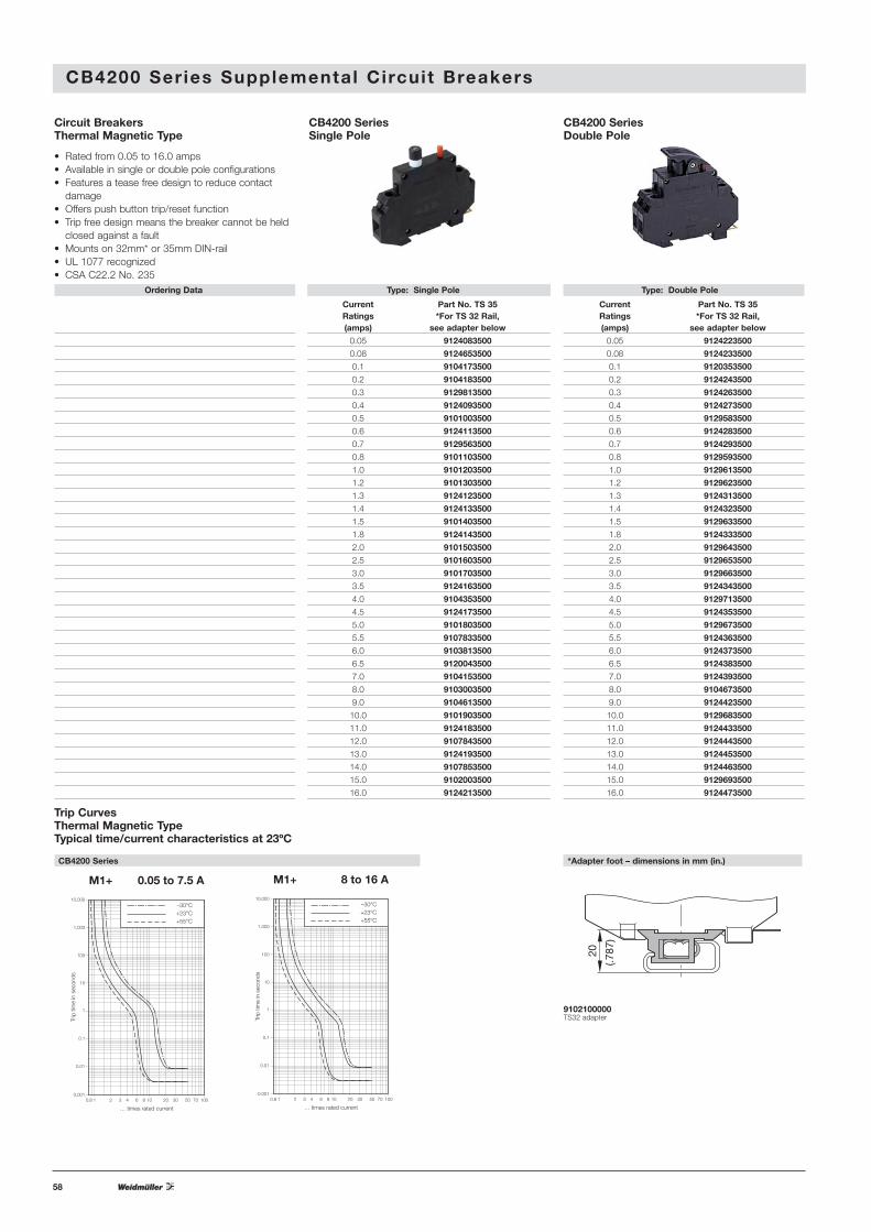
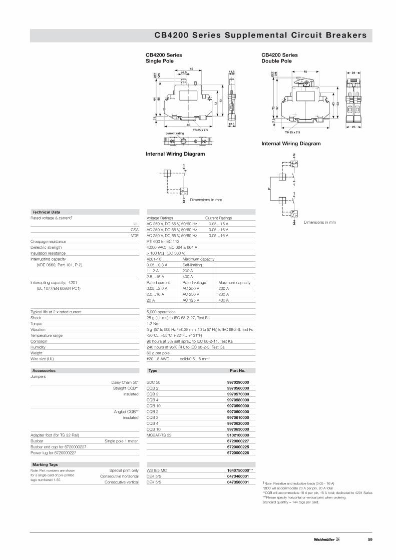
CB4200 Ser ies Supplemental Circuit Breakers
CB4200 SeriesSingle Pole
CB4200 SeriesDouble Pole
Circuit BreakersThermal Magnetic Type
• Rated from 0.05 to 16.0 amps• Available in single or double pole configurations• Features a tease free design to reduce contact
damage• Offers push button trip/reset function• Trip free design means the breaker cannot be held
closed against a fault• Mounts on 32mm* or 35mm DIN-rail• UL 1077 recognized• CSA C22.2 No. 235
0.8 1 2 3 4 6 8 10 20 30 50 70 1000.001
0.01
0.1
1
10
100
1,000
10,000
… times rated current
Trip
tim
e in
sec
onds
–30°C+23°C+55°C
M1+ 0.05 to 7.5 A
0.8 1 2 3 4 6 8 10 20 30 50 70 1000.001
0.01
0.1
1
10
100
1,000
10,000
… times rated current
Trip
tim
e in
sec
onds
–30°C+23°C+55°C
M1+ 8 to 16 A
Trip CurvesThermal Magnetic TypeTypical time/current characteristics at 23ºC
CB4200 Series *Adapter foot – dimensions in mm (in.)
9102100000TS32 adapter
20
(.787
)
Ordering Data Type: Single Pole Type: Double Pole
Current Part No. TS 35 Current Part No. TS 35Ratings *For TS 32 Rail, Ratings *For TS 32 Rail,(amps) see adapter below (amps) see adapter below
0.05 9124083500 0.05 9124223500
0.08 9124653500 0.08 9124233500
0.1 9104173500 0.1 9120353500
0.2 9104183500 0.2 9124243500
0.3 9129813500 0.3 9124263500
0.4 9124093500 0.4 9124273500
0.5 9101003500 0.5 9129583500
0.6 9124113500 0.6 9124283500
0.7 9129563500 0.7 9124293500
0.8 9101103500 0.8 9129593500
1.0 9101203500 1.0 9129613500
1.2 9101303500 1.2 9129623500
1.3 9124123500 1.3 9124313500
1.4 9124133500 1.4 9124323500
1.5 9101403500 1.5 9129633500
1.8 9124143500 1.8 9124333500
2.0 9101503500 2.0 9129643500
2.5 9101603500 2.5 9129653500
3.0 9101703500 3.0 9129663500
3.5 9124163500 3.5 9124343500
4.0 9104353500 4.0 9129713500
4.5 9124173500 4.5 9124353500
5.0 9101803500 5.0 9129673500
5.5 9107833500 5.5 9124363500
6.0 9103813500 6.0 9124373500
6.5 9120043500 6.5 9124383500
7.0 9104153500 7.0 9124393500
8.0 9103003500 8.0 9104673500
9.0 9104613500 9.0 9124423500
10.0 9101903500 10.0 9129683500
11.0 9124183500 11.0 9124433500
12.0 9107843500 12.0 9124443500
13.0 9124193500 13.0 9124453500
14.0 9107853500 14.0 9124463500
15.0 9102003500 15.0 9129693500
16.0 9124213500 16.0 9124473500
59
CB4200 Ser ies Supplemental Circuit Breakers
Technical Data
Rated voltage & current†
UL
CSA
VDE
Creepage resistanceDielectric strengthInsulation resistanceInterrupting capacity
(VDE 0660, Part 101, P-2)
Interrupting capacity; 4201
(UL 1077/EN 60934 PC1)
Typical life at 2 x rated current
Shock
Torque
Vibration
Temperature range
Corrosion
Humidity
Weight
Wire size (UL)
Accessories
JumpersDaisy Chain 50*
Straight CQB**
insulated
Angled CQB**insulated
Adapter foot (for TS 32 Rail)Busbar Single pole 1 meter
Busbar end cap for 6720000227
Power lug for 6720000227
Marking Tags
Special print only
Consecutive horizontal
Consecutive vertical
Voltage Ratings Current Ratings
AC 250 V, DC 65 V, 50/60 Hz 0.05…16 A
AC 250 V, DC 65 V, 50/60 Hz 0.05…16 A
AC 250 V, DC 65 V, 50/60 Hz 0.05…16 A
PTI 600 to IEC 112
4,000 VAC; IEC 664 & 664 A
> 100 MM (DC 500 V)
4201-10 Maximum capacity
0.05…0.8 A Self-limiting
1…2 A 200 A
2.5…16 A 400 A
Rated current Rated voltage Maximum capacity
0.05…2.0 A AC 250 V 200 A
2.0…16 A AC 250 V 200 A
20 A AC 125 V 400 A
5,000 operations
25 g (11 ms) to IEC 68-2-27, Test Ea
1.2 Nm
5 g (57 to 500 Hz / ±0.38 mm, 10 to 57 Hz) to IEC 68-2-6, Test Fc
-30°C…+55°C (-22°F…+131°F)
96 hours at 5% salt spray, to IEC 68-2-11, Test Ka
240 hours at 95% RH, to IEC 68-2-3, Test Ca
60 g per pole
#20…8 AWG solid/0.5…6 mm2
Type Part No.
BDC 50 9970290000
CQB 2 9970560000
CQB 3 9970570000
CQB 4 9970580000
CQB 10 9970590000
CQB 2 9970600000
CQB 3 9970610000
CQB 4 9970620000
CQB 10 9970630000
MCBAF/TS 32 9102100000
6720000227
6720000225
6720000226
WS 8/5 MC 1640750000***
DEK 5/5 0473460001
DEK 5/5 0473560001 †Note: Resistive and inductive loads (0.05 - 16 A)*BDC will accommodate 20 A per pin, 20 A total**CQB will accommodate 18 A per pin, 18 A total; dedicated to 4201 Series***Please specify horizontal or vertical print when ordering. Standard quantity = 144 tags per card.
Note: Part numbers are shown for a single card of pre-printed tags numbered 1-50.
Internal Wiring Diagram
Internal Wiring Diagram
CB4200 SeriesSingle Pole
CB4200 SeriesDouble Pole
Dimensions in mm
Dimensions in mm
60
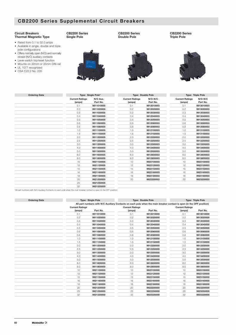
CB2200 Ser ies Supplemental Circuit Breakers
CB2200 SeriesSingle Pole
CB2200 SeriesDouble Pole
CB2200 SeriesTriple Pole
Ordering Data Type: Single Pole* Type: Double Pole Type: Triple Pole
Current Ratings N/O Aux. Current Ratings N/O-N/C Current Ratings N/O-N/C(amps) Part No. (amps) Part No. (amps) Part No.
0.1 9911010005 0.1 9912010003 0.1 9913010003
0.2 9911020005 0.2 9912020003 0.2 9913020003
0.3 9911030005 0.3 9912030003 0.3 9913030003
0.4 9911040005 0.4 9912040003 0.4 9913040003
0.5 9911050005 0.5 9912050003 0.5 9913050003
0.6 9911060005 0.6 9912060003 0.6 9913060003
0.8 9911080005 0.8 9912080003 0.8 9913080003
1.0 9911100005 1.0 9912100003 1.0 9913100003
1.5 9911150005 1.5 9912150003 1.5 9913150003
2.0 9911200005 2.0 9912200003 2.0 9913200003
2.5 9911250005 2.5 9912250003 2.5 9913250003
3.0 9911300005 3.0 9912300003 3.0 9913300003
4.0 9911400005 4.0 9912400003 4.0 9913400003
5.0 9911500005 5.0 9912500003 5.0 9913500003
6.0 9911600005 6.0 9912600003 6.0 9913600003
8.0 9911800005 8.0 9912800003 8.0 9913800003
10 9921100005 10 9922100003 10 9923100003
12 9921120005 12 9922120003 12 9923120003
15 9921150005 15 9922150003 15 9923150003
16 9921160005 16 9922160003 16 9923160003
18 9921180005 18 9922180003 18 9923180003
20 9921200005 20 9922200003 20 9923200003
25 9921250005
32 9921320005
*All part numbers with N/O Auxiliary Contacts on each pole when the main breaker contact is open (in the OFF position)
Circuit BreakersThermal Magnetic Type
• Rated from 0.1 to 32.0 amps• Available in single, double and triple
pole configurations• Offers normally open (N/O) and normally
closed (N/C) auxiliary contacts• Lever-switch trip/reset function• Mounts on 32mm or 35mm DIN-rail• UL 1077 recognized• CSA C22.2 No. 235
Ordering Data Type: Single Pole Type: Double Pole Type: Triple Pole
Current Ratings Current Ratings Current Ratings(amps) Part No. (amps) Part No. (amps) Part No.
0.1 9911010000 0.1 9912010000 0.1 9913010000
0.2 9911020000 0.2 9912020000 0.2 9913020000
0.3 9911030000 0.3 9912030000 0.3 9913030000
0.4 9911040000 0.4 9912040000 0.4 9913040000
0.5 9911050000 0.5 9912050000 0.5 9913050000
0.6 9911060000 0.6 9912060000 0.6 9913060000
0.8 9911080000 0.8 9912080000 0.8 9913080000
1.0 9911100000 1.0 9912100000 1.0 9913100000
1.5 9911150000 1.5 9912150000 1.5 9913150000
2.0 9911200000 2.0 9912200000 2.0 9913200000
2.5 9911250000 2.5 9912250000 2.5 9913250000
3.0 9911300000 3.0 9912300000 3.0 9913300000
4.0 9911400000 4.0 9912400000 4.0 9913400000
5.0 9911500000 5.0 9912500000 5.0 9913500000
6.0 9911600000 6.0 9912600000 6.0 9913600000
8.0 9911800000 8.0 9912800000 8.0 9913800000
10 9921100000 10 9922100000 10 9923100000
12 9921120000 12 9922120000 12 9923120000
15 9921150000 15 9922150000 15 9923150000
16 9921160000 16 9922160000 16 9923160000
18 9921180000 18 9922180000 18 9923180000
20 9921200000 20 9922200000 20 9923200000
25 9921250000 25 9922250000 25 9923250000
32 9921320000 32 9922320000 32 9923320000
All part numbers with N/C Auxiliary Contacts on each pole when the main breaker contact is open (in the OFF position)

61
Technical Data
Rated voltage & current†
UL
CSA
VDE
Auxiliary contacts
Creepage resistance
Dielectric strength
Insulation resistance
Interrupting capacity
(VDE 0660, Part 101, P-2)
Interrupting capacity(UL 1077/EN 60934 PC1)
Typical life at 2 x rated currentShockTorque Nm (lb. in.)VibrationTemperature rangeCorrosionHumidityWeightWire size (UL)
AccessoriesJumpers Daisy Chain 50
Busbars
Marking TagsSpecial print only
Consecutive horizontal
Consecutive vertical
CB2200 Ser ies Supplemental Circuit Breakers
Voltage Ratings Current Ratings
277 / 480 VAC (50/60 Hz); 65 VDC 0.1…32 A
277 / 480 VAC (50/60 Hz); 65 VDC 0.1…32 A
250 / 415 VAC / 65 VDC 0.1…32 A
250 VAC / 65 VDC, 1 A
PTI 600 to IEC 112
3,000 VAC; IEC 664 & 664 A
> 100 MM (DC 500 V)
Rated current Rated voltage Rupture capacity (3 times)
0.05…0.8 A 250 / 415 VAC 400 A
6…32 A 250 / 415 VAC 800 A
Rated current Rated voltage Max. rupture capacity (3 times)
0.1…16 A 277 / 480 VAC 5000 A
20…32 A 277 / 480 VAC 2000 A
0.1…32 A 65 VDC 2000 A
5,000 operations
25 g (11 ms) to IEC 68-2-27, Test Ea
0.6 (5.3) Auxiliary contact: 0.5 (4.4)
5 g (57 to 500 Hz / ±0.38 mm, 10 to 57 Hz) to IEC 68-2-6, Test Fc
-30…+60°C (-22°F…+140°F)
96 hours at 5% salt spray, to IEC 68-2-11, Test Ka
240 hours at 95% RH, to IEC 68-2-3, Test Ca
Approximately 60 g per pole
max 6 mm2…8 AWG max 1.5 mm2…14 AWG (Aux. contact)
Type Part No.
BDC 50, 20 A maximum 9970290000
1 pole (CB2200) 9986510000
2 pole (CB2200) 9987360000
DEK 5/6 0490360000*
DEK 5/6 0468660001DEK 5/6 0468760001
CB2200 Series
1 2 3 4 5 6
Dimensions in mm
†Note: Resistive and inductive loads (0.05 - 16 A)*Please specify horizontal or vertical print when ordering.
Note: Part numbers shown are for a single card of pre-printed tags numbered 1-50.
Trip Curves—Thermal Magnetic TypeTypical time/current characteristics at 23ºC
CB2200 Series
F1 0.1 to 32 A
1
.8 1 2 3 4 6 8 10 20 30 50 70 1000.001
0.01
0.1
10
100
1,000
10,000
…times rated current
Trip
tim
e in
sec
onds
–30°C+23°C+55°C
10
T
-M1 0.1 to 7.5 A
DC
AC
.8 1 2 3 4 6 8 10 20 30 50 70 1000.001
0.01
0.1
10
100
1,000
10,000
…times rated current
Trip
tim
e in
sec
onds
–30°CAC +23°CDC +23°C
+55°C
.8 1 2 3 4 6 8 10 20 30 50 70 1000.001
0.01
0.1
1
10
100
1,000
10,000
…times rated current
Trip
tim
e in
sec
onds
–30°C+23°C+55°C
-T1 8 to 32 A
-T1 0.1 to 7.5 A
.8 1 2 3 4 6 8 10 20 30 50 70 1000.001
0.01
0.1
10
100
1,000
10,000
…times rated current
Trip
tim
e in
sec
onds
–30°C+23°C+55°C
-M1 8 to 32 A
DC
AC
.8 1 2 3 4 6 8 10 20 30 50 70 1000.001
0.01
0.1
10
100
1,000
10,000
…times rated current
Trip
tim
e in
sec
onds
–30°CAC +23°CDC +23°C
+55°C
62
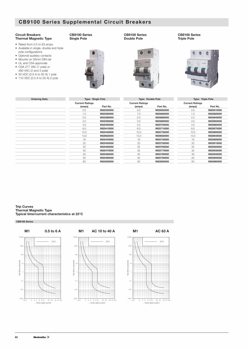
CB9100 Ser ies Supplemental Circuit Breakers
Circuit BreakersThermal Magnetic Type
• Rated from 0.5 to 63 amps• Available in single, double and triple
pole configurations• Optional auxiliary contacts• Mounts on 35mm DIN-rail• UL and CSA approvals• CSA 277 VAC (1 pole) or
480 VAC (2 and 3 pole)• 50 VDC (0.5 A to 50 A) 1 pole• 110 VDC (0.5 A to 50 A) 2 pole
CB9100 SeriesSingle Pole
CB9100 SeriesDouble Pole
CB9100 SeriesTriple Pole
Ordering Data Type: Single Pole Type: Double Pole Type: Triple Pole
Current Ratings Current Ratings Current Ratings(amps) Part No. (amps) Part No. (amps) Part No.
0.5 9925350000 0.5 9925650000 0.5 9925810000
1.0 9925360000 1.0 9925660000 1.0 9925820000
2.0 9925380000 2.0 9925680000 2.0 9925840000
3.0 9925390000 3.0 9925690000 3.0 9925850000
4.0 9925400000 4.0 9925700000 4.0 9925860000
6.0 9925410000 6.0 9925710000 6.0 9925870000
10.0 9925430000 10.0 9925730000 10.0 9925890000
13.0 9929820000 13.0 9929830000 13.0 9929840000
16 9925440000 16 9925740000 16 9925900000
20 9925450000 20 9925750000 20 9925910000
25 9925460000 25 9925760000 25 9925920000
32 9925470000 32 9925770000 32 9925930000
40 9925480000 40 9925780000 40 9925940000
50 9925490000 50 9925790000 50 9925950000
63 9925500000 63 9925800000 63 9925960000
Trip CurvesThermal Magnetic TypeTypical time/current characteristics at 23°C
0.8 1 2 3 4 6 8 10 20 30 50 70 1000.001
0.01
0.1
1
10
100
1,000
10,000
… times rated current
Trip
tim
e in
sec
onds
23°C
M1 0.5 to 6 A
0.8 1 2 3 4 6 8 10 20 30 50 70 1000.001
0.01
0.1
1
10
100
1,000
10,000
… times rated current
Trip
tim
e in
sec
onds
23°C
M1 AC 10 to 40 A
0.8 1 2 3 4 6 8 10 20 30 50 70 1000.001
0.01
0.1
1
10
100
1,000
10,000
… times rated current
Trip
tim
e in
sec
onds
23°C
M1 AC 63 A
CB9100 Series
63
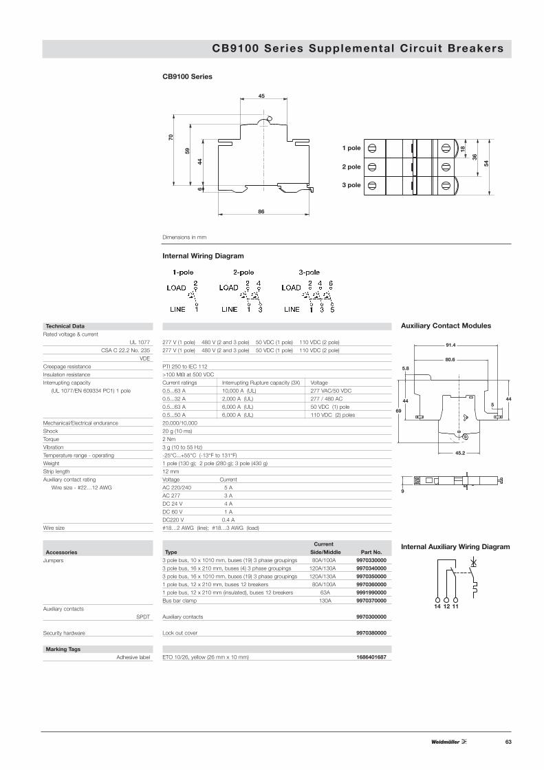
CB9100 Ser ies Supplemental Circuit Breakers
Technical DataRated voltage & current
UL 1077
CSA C 22.2 No. 235
VDE
Creepage resistance
Insulation resistance
Interrupting capacity
(UL 1077/EN 609334 PC1) 1 pole
Mechanical/Electrical endurance
Shock
Torque
Vibration
Temperature range - operating
Weight
Strip length
Auxiliary contact rating
Wire size - #22…12 AWG
Wire size
Accessories
Jumpers
Auxiliary contacts
SPDT
Security hardware
Marking Tags
Adhesive label
277 V (1 pole) 480 V (2 and 3 pole) 50 VDC (1 pole) 110 VDC (2 pole)
277 V (1 pole) 480 V (2 and 3 pole) 50 VDC (1 pole) 110 VDC (2 pole)
PTI 250 to IEC 112
>100 MM at 500 VDC
Current ratings Interrupting Rupture capacity (3X) Voltage
0.5...63 A 10,000 A (UL) 277 VAC/50 VDC
0.5...32 A 2,000 A (UL) 277 / 480 AC
0.5...63 A 6,000 A (UL) 50 VDC (1) pole
0.5...50 A 6,000 A (UL) 110 VDC (2) poles
20,000/10,000
20 g (10 ms)
2 Nm
3 g (10 to 55 Hz)
-25°C...+55°C (-13°F to 131°F)
1 pole (130 g); 2 pole (280 g); 3 pole (430 g)
12 mm
Voltage Current
AC 220/240 5 A
AC 277 3 A
DC 24 V 4 A
DC 60 V 1 A
DC220 V 0.4 A
#18…2 AWG (line); #18…3 AWG (load)
Current
Type Side/Middle Part No.
3 pole bus, 10 x 1010 mm, buses (19) 3 phase groupings 80A/100A 9970330000
3 pole bus, 16 x 210 mm, buses (4) 3 phase groupings 120A/130A 9970340000
3 pole bus, 16 x 1010 mm, buses (19) 3 phase groupings 120A/130A 9970350000
1 pole bus, 12 x 210 mm, buses 12 breakers 80A/100A 9970360000
1 pole bus, 12 x 210 mm (insulated), buses 12 breakers 63A 9991990000
Bus bar clamp 130A 9970370000
Auxiliary contacts 9970300000
Lock out cover 9970380000
ETO 10/26, yellow (26 mm x 10 mm) 1686401687
Internal Wiring Diagram
9
45.2
69
44 445
5.8
80.6
91.4
Internal Auxiliary Wiring Diagram
Auxiliary Contact Modules
Dimensions in mm
CB9100 Series
45
1 pole
2 pole
3 pole
86
644
18
36
54
59
70
14 12 11