invent3d printer assembly instructions v6
TRANSCRIPT

INVENT3DPrinterKitAssemblyInstructions
AST2©10/26/161
INVENT3DPrinterKit
AssemblyInstructions
Version6

INVENT3DPrinterKitAssemblyInstructions
AST2©10/26/162
I.PrinterKitCaseLayout
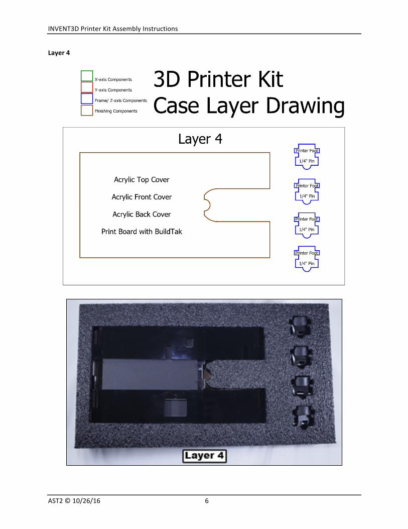
Theprinterkitcomponentsareorganizedinfourlayersintheprinterkitcase.Thecustom-cutfoamlayersallowcomponentsandsubassembliestobere-packedinthesamemannerwhendisassembled.Theselayersarelabeledfromthetopdownwithinthecase,meaningLayer1isthetoplayerandLayer4isthebottomlayer.Adetaileddrawingandphoto(s)ofeachlayerisincludedbelowtoensurethatallpiecesareaccountedforandforeaseofsubsequentassemblies.

INVENT3DPrinterKitAssemblyInstructions
AST2©10/26/163
Layer1

INVENT3DPrinterKitAssemblyInstructions
AST2©10/26/164
Layer2

INVENT3DPrinterKitAssemblyInstructions
AST2©10/26/165
Layer3
INVENT3DPrinterKitAssemblyInstructions
AST2©10/26/166
Layer4

INVENT3DPrinterKitAssemblyInstructions
AST2©10/26/167
II.GeneralAssemblyInstructions
The INVENT3DPrinter is a sophisticated, electro-mechanical system. It is imperative that allproceduresarereadandfollowedexactlytoavoiddamagethatwouldpreventfullandcorrectassemblyand/oroperationoftheprinter. AST2 isnotresponsible fordamageresultingfromfailuretofollowprocedures.
The procedures will provide detailed information about each printer assembly and printercomponent that will be used to build a functioning INVENT3D Printer. Procedures are alsoprovidedfordisassemblyoftheprinterforstorageandreassemblybysubsequentusers.
It is imperativeto implementthe followinggeneralguidancewhenassemblingthe INVENT3Dprinterkit:
Unless otherwise noted, printer kit components and subassemblies are not to bedisassembled;disassemblyshouldreturntheprinterkittothesameconditioninwhichitarrived.
Screwsthatareblackanodizedshouldnotberemoved. Alwayshandtightenscrewsfirsttoensurethatthescrewisthreadedproperlyandavoid
cross-threading. ScrewsdoNOTneedexcessiveforcetotighten. Thumbscrewsgenerallydonotrequireawrench Ifascrewishardtoturn,makesurethatthecorrectscrewisbeingusedinthecorrect
location.Contact Applied Systems & Technology Transfer, LLC (AST2) if any parts are missing or notfunctioning properly. Leave a note in the kit so that the other users are aware of themissing/malfunctioning parts to ensure that corrective actions are completed prior to itsassembly. AST2 welcomes and appreciates any comments on the printer, assembly oroperationasfeedbackisusedinitscontinuousimprovementprocess.
Supportviaon-lineticket(recommended)

INVENT3DPrinterKitAssemblyInstructions
AST2©10/26/168
III.DetailedAssemblyInstructionsNOTE:RefertoCaseLayerDrawingsandAlphabeticalPartsListingtofindpartsreferencedUsetoolsintoolkittoassemble.
1. ConnecttheleftsideassemblyandtherightsideassemblywiththebottomplateusingfourM5x18flatheadscrewsfromthez-axisplasticbox
2. Connectprinterfeettotheprinterlegs.Therearecurrentlytwovariationsofprinterfootmountinghardware:hitchpins(newermodels)orscrewswithlocknuts(oldermodels).

INVENT3DPrinterKitAssemblyInstructions
AST2©10/26/169
3. Removeleftsidechannelbyunscrewingthefourblackthumbscrews.Screwthetwogreenthumbscrewsthroughtheleftsideframeandintotheprinterleguntiltight.Re-attachtheleftsidechannelwiththefourblackthumbscrews.
4. Repeatforrightsidechannel.

INVENT3DPrinterKitAssemblyInstructions
AST2©10/26/1610
5. Mountthez-axismotortothebottomplateusingthetwogoldthumbscrewsandthez-axismotormount.NOTE:wireplacementbelow!Wiresleavemotorfromrearofprinter.
6. RemovetheZ-axisknobbylooseningthesmallsetscrew.Removethefourscrewsfromthez-axiscarriage.ThreadtheL-platesubassemblyontothez-axisleadscrewandreplacethez-axisknob.

INVENT3DPrinterKitAssemblyInstructions
AST2©10/26/1611
7. Resttheprinterassemblyonitsleftside.AligntheL-platewiththeholesonthecarriageandinsertthefourscrewsremovedinthepreviousstepandtighten.
8. Attachthefouridlerboltstothey-axisplate.NOTE:onenutisoneachsideofplate.

INVENT3DPrinterKitAssemblyInstructions
AST2©10/26/1612
9. RemovefourscrewsandlockwashersfromY-axiscarriage.Alignthediamondplateandattachtothecarriagewiththefourscrews.NOTE:washersgoontopofplate.
10. AttachtheY-axisplatetotheL-plateusingthreeM5flatheadscrewsfromtheY-axisplasticbox.

INVENT3DPrinterKitAssemblyInstructions
AST2©10/26/1613
11. AttachtheY-axismotortotheL-plateassemblyusingscrewsfoundinY-axismotor.

INVENT3DPrinterKitAssemblyInstructions
AST2©10/26/1614
12. RemovetheZ-axisknobandalignthetopplate.ConnectthetopplatetotheleftandrightsidesusingM5flatheadscrewsfoundintheZ-axisplasticbox.

INVENT3DPrinterKitAssemblyInstructions
AST2©10/26/1615
13. TakebearingfromX-axisboxandslidethebearingontheZ-axisleadscrew.
ReplacetheZ-axisknob.InserttheyellowthumbscrewintothefronttotheZ-axisplateneartheZ-axisknob.Attachtheidlerbolttothetopplate.

INVENT3DPrinterKitAssemblyInstructions
AST2©10/26/1616
14. Attachx-axismotor,makingsurethattheshortscrewisinthefrontleftcorner.

INVENT3DPrinterKitAssemblyInstructions
AST2©10/26/1617
15. AttachX-axislimitswitchtotheextruderbottom.NOTE:Useplierstotightenifneeded.

INVENT3DPrinterKitAssemblyInstructions
AST2©10/26/1618
16. AttachtheextruderbottomtotheX-axiscarriageusingthefourscrewsfoundintheX-axiscarriage.(RefertotopofphotoinfirstimageunderStep17).
17. Slidehotendintotheslotontheextruderbottomuntilitseatsflushwiththeendoftheslot.Refertobothphotosbelow.

INVENT3DPrinterKitAssemblyInstructions
AST2©10/26/1619
18. ConnectX-axisbelttotheX-axismotorandidlerbolt.NOTE:beltteethfaceinwards.Tightenthebeltbyslidingtheidlerboltbackandtightenwithwrench.Checktensiononthebelt–thereshouldbesomeresistancewithsqueezingthebelttogetherwithyourfingers.
19. Removethescrewsfromthebeltclamp.Aligntheholesinthebeltclampwiththoseintheextruderbottom.Reconnecttheextruderbottomtothebeltclampwithscrewspreviouslyremoved.

INVENT3DPrinterKitAssemblyInstructions
AST2©10/26/1620
20. ConnecttheY-axisbelttotheY-axismotorandidlerbolts.NOTE:beltgoesaroundallFOURidlerboltsandY-axismotor.Tightenthebeltbyslidingtheslottedidlerboltbackandtighten.Checktensiononthebelt–thereshouldbesomeresistancewithsqueezingthebelttogetherwithyourfingers.
21. RemovethescrewsfromtheY-axisbeltclamp.
Alignthediamondplatewiththeholesinthebeltclamp.Replacethescrewsandtighten.

INVENT3DPrinterKitAssemblyInstructions
AST2©10/26/1621
22. Attachthefilamentdrivetotheextrudermotor.
23. Placetheextrudermotorontotheextruderbottom.SecuretheextrudertopovertheextrudermotorusingthetwosilverthumbscrewsfoundintheX-axisbox.
INVENT3DPrinterKitAssemblyInstructions
AST2©10/26/1622
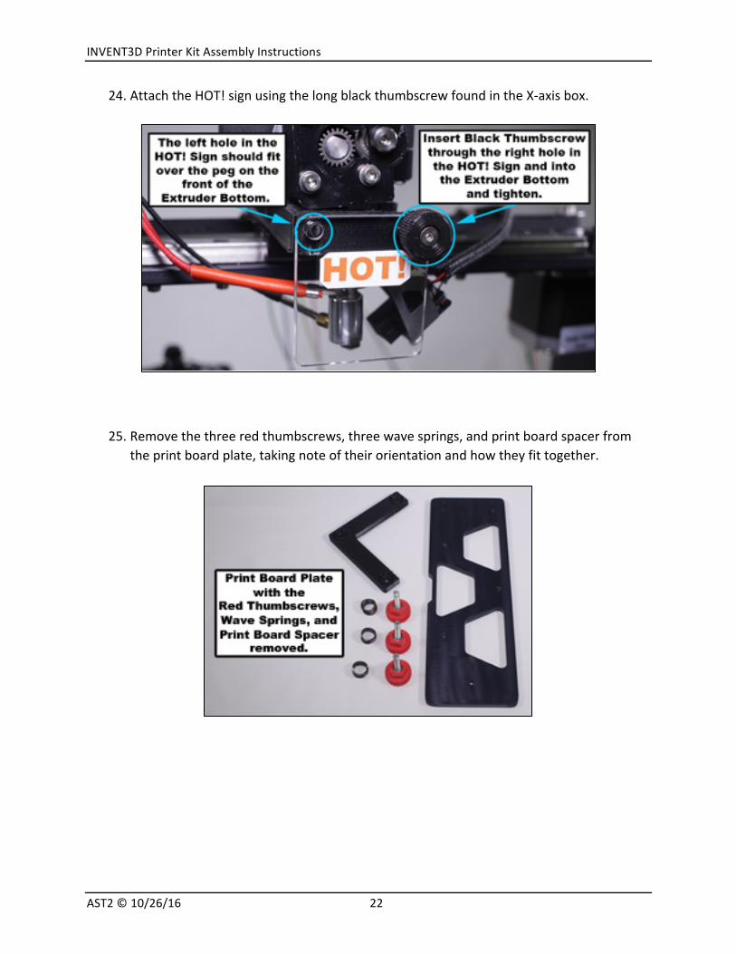
24. AttachtheHOT!signusingthelongblackthumbscrewfoundintheX-axisbox.
25. Removethethreeredthumbscrews,threewavesprings,andprintboardspacerfromtheprintboardplate,takingnoteoftheirorientationandhowtheyfittogether.

INVENT3DPrinterKitAssemblyInstructions
AST2©10/26/1623
26. Attachtherearboardclampstotheprintboardplateandhandtighten.Attachthefrontboardclampusingthebluethumbscrew.
27. Slidetheprintboardintotherearclampsontheprintboardplateuntiltheprintboardiscompletelyseatedintotherearclamps.Slidethefrontclampintothenotchonthefrontoftheprintboardandtighten.Tightenscrewsinrearclampstolockclampsintoplace.Loosenthebluethumbscrewandremovetheprintboard.

INVENT3DPrinterKitAssemblyInstructions
AST2©10/26/1624
28. Placetheprintboardspacerontothediamondplateandalignthethreeholes.Insertthethreewavespringsintotheprintboardspacer.NOTE:Wavespringsfitinrecessedareasonprintboardspacer.

INVENT3DPrinterKitAssemblyInstructions
AST2©10/26/1625
29. Placeprintboardplateoverthethreewavesprings;ensuretheyremainseated.Insertandtightenallthreerightredthumbscrewssotheirendsareaboutflushwiththetopoftheprintboardplate.
PHOTOTAKENFROMABOVEPRINTER,LOOKINGDOWN
PHOTOTAKENFROMBELOWPRINTER,LOOKINGUP

INVENT3DPrinterKitAssemblyInstructions
AST2©10/26/1626
30. Insertthez-axisendstopintothetopplateandtightenituntilabout1”extendsbelowthetopplate.

INVENT3DPrinterKitAssemblyInstructions
AST2©10/26/1627
31. AttachtheRAMBoboardwithusingthetwoorangethumbscrews.
32. Untangleallwires.Removetherightchannel.PassthefanwiresfromtheRAMBoboard,throughtheholeintherightsideframe,andconnecttothehotendfans.NOTE:Fanwiresmaybeblackorredandblack.
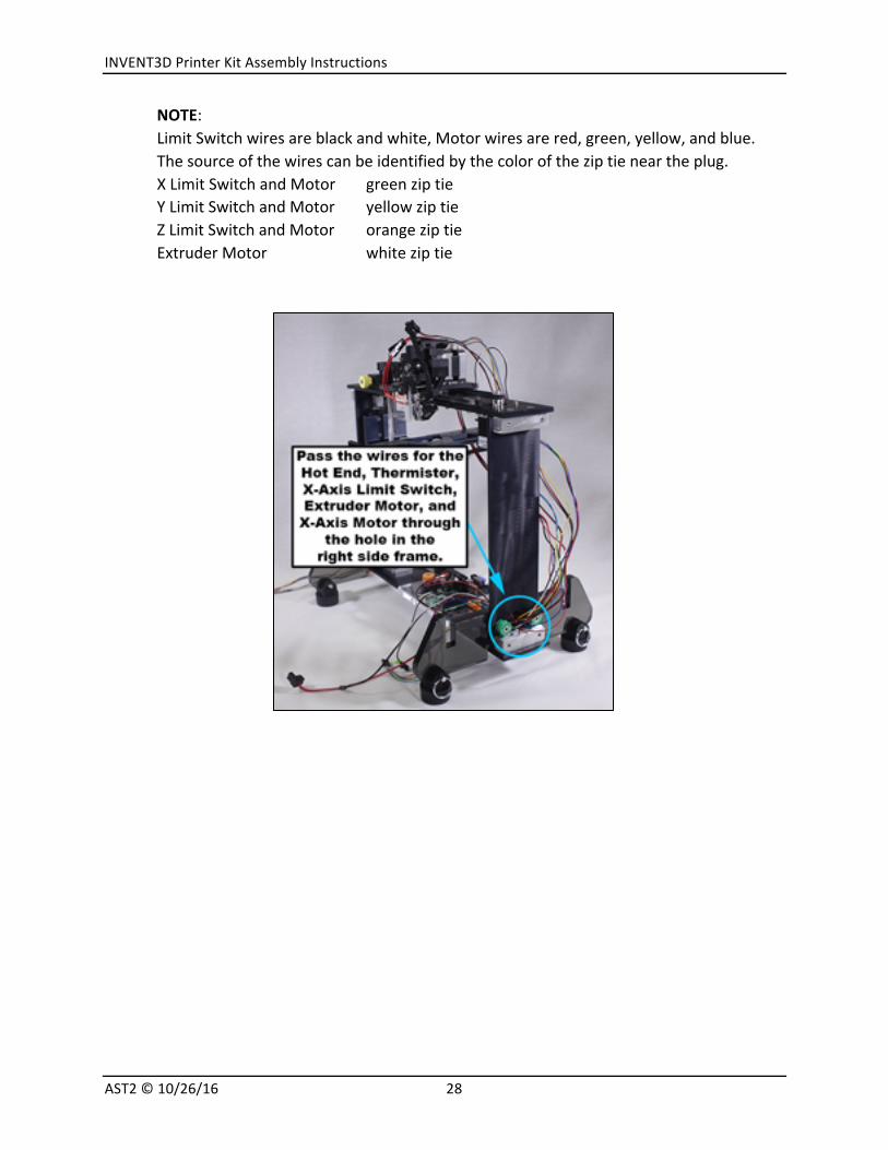
Passrightsidewires(hotendwire,thermistorwire,fanwires,extrudermotorwire,x-axislimitswitchwire,x-axismotorwire)throughtheholeintherightsideframe.
INVENT3DPrinterKitAssemblyInstructions
AST2©10/26/1628
NOTE:LimitSwitchwiresareblackandwhite,Motorwiresarered,green,yellow,andblue.Thesourceofthewirescanbeidentifiedbythecoloroftheziptieneartheplug.XLimitSwitchandMotor greenziptieYLimitSwitchandMotor yellowziptieZLimitSwitchandMotor orangeziptieExtruderMotor whiteziptie

INVENT3DPrinterKitAssemblyInstructions
AST2©10/26/1629
Grouphotendwirestogetherandinsertintothelongerwiresleeve(itisslicedlengthwise)justpastthequickdisconnectsuntilapproximately3”ofwireareinserted.Passziptiesthroughslotsinextrudertopandtightentofastenwiresleeveinplace.Inserttheextrudermotorwireandx-axislimitswitchwireintothewiresleeveuntilapproximately3”ofwireareinserted.Attachziptiewhereextrudermotorandx-axislimitswitchwiresenterthewiresleeve.Insertallwiresfortheremainingdistanceofthesleeve.
INVENT3DPrinterKitAssemblyInstructions
AST2©10/26/1630
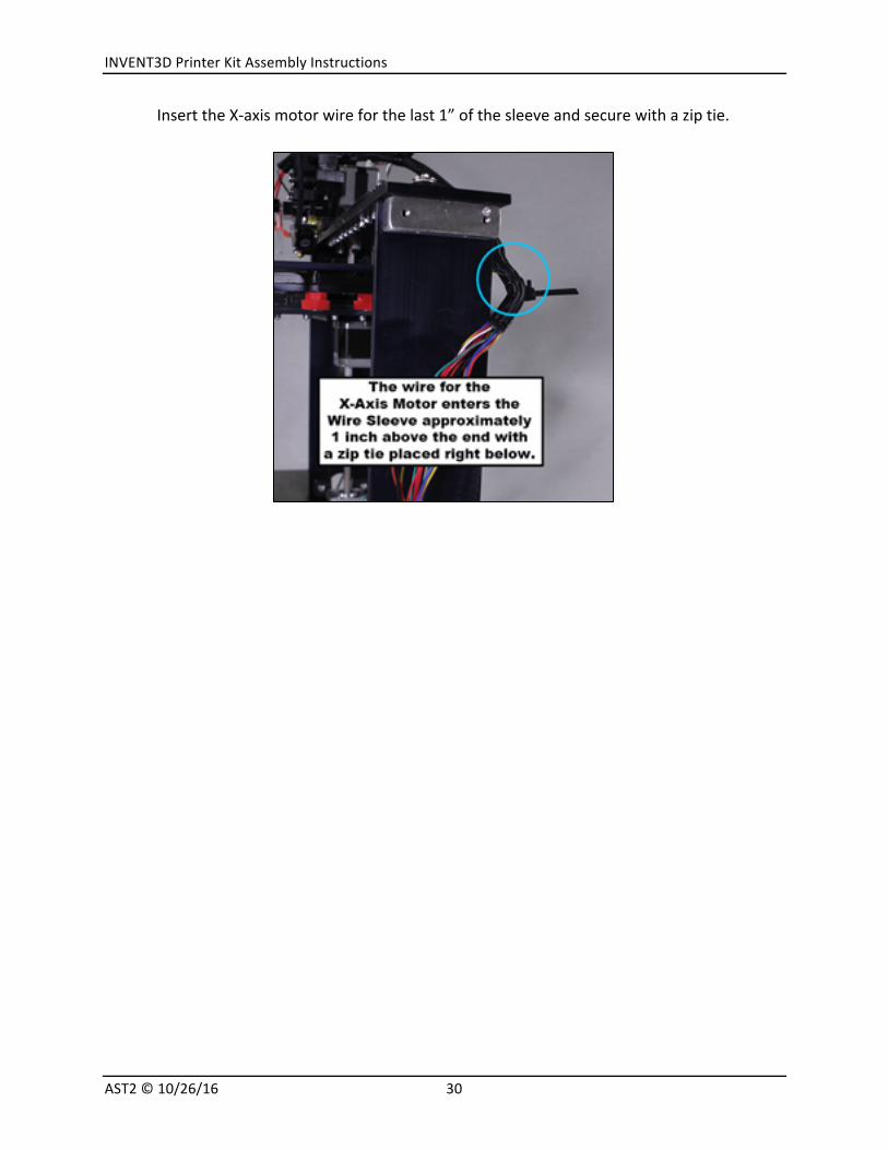
InserttheX-axismotorwireforthelast1”ofthesleeveandsecurewithaziptie.

INVENT3DPrinterKitAssemblyInstructions
AST2©10/26/1631
PlugallwiresintoappropriateplacesontheRAMBoboard.PlaceaziptiearoundtherightsidewiresneartheRAMBoboard.

INVENT3DPrinterKitAssemblyInstructions
AST2©10/26/1632
Replacetherightsidechannelensuringthatthewirespassthroughthenotchatthetop.
33. Removeleftsidechannel.Passleftsidewires(y-axismotor,y-axislimitswitch,z-axislimitswitch)throughtheholeintheleftsideframe.

INVENT3DPrinterKitAssemblyInstructions
AST2©10/26/1633
NOTE:LimitSwitchwiresareblackandwhite,Motorwiresarered,green,yellow,andblue.Thesourceofthewirescanbeidentifiedbythecoloroftheziptieneartheplug.XLimitSwitchandMotor greenziptieYLimitSwitchandMotor yellowziptieZLimitSwitchandMotor orangeziptie
Insertthethreewiresintotheshorterwiresleeve(slicedlengthwise).Attachaziptieoneachendofthesleeve.

INVENT3DPrinterKitAssemblyInstructions
AST2©10/26/1634
PlugleftsidewiresandZ-axismotorwire,intoappropriatelocationsonRAMBoboard.NeatlyarrangethewiresandsecurewithziptieneartheirconnectiontoRAMBoboard.PullexcesswirethoughleftsideframeandslidewiresintheslotbetweentheZ-axismotorandleftframe.

INVENT3DPrinterKitAssemblyInstructions
AST2©10/26/1635
34. Attachthespoolholdertotheleftsidechannelusingthewhitethumbscrews.Replacetheleftsidechannelandattachfilamentguideontopatsametime.Ensurethatwirescleanlypassthroughthenotchinthechannelwithoutpinching.Theziptiesshouldbeontheoutside.
35. Placefrontacryliccoverintotheslotsontheprinterlegs.PlaceLCDintotheslotsonthefrontcover.

INVENT3DPrinterKitAssemblyInstructions
AST2©10/26/1636
36. CrosstheLCDgraywires(bottompicture).PlugtheLCDgraywiresintotheRAMBoboard(diagramandpictureonnextpage).

INVENT3DPrinterKitAssemblyInstructions
AST2©10/26/1637
37. Attachthepowerplugbreakoutboardtotherearcover.Inserttherearcoverintotheslotsontheprinterlegs.PlugthepowerplugbreakoutboardwireintotheRAMBoboard.

INVENT3DPrinterKitAssemblyInstructions
AST2©10/26/1638
38. Replacetheprintboardontotheprintboardplatebyinsertingitcompletelyintotherearclamps,thenpressthefrontboardclamptightlyagainsttheprintboardandtightenthebluefrontboardclampthumbscrew.
39. Placetopcoverontotheprinterlegs.
40. PlugACadapterintothebackoftheprinter.

INVENT3DPrinterKitAssemblyInstructions
AST2©10/26/1639
PrinterBoardLevelingProcess
Theprintboard’slevelisdeterminedbythethreeredprintboardlevelingthumbscrewslocatedbelowtheprintboardandtheoneblackZ-axisendstopscrewlocatedonthetop, at theback left (it is the smallerblack screw). The three redprintboard levelingthumbscrewsletyouadjustthetiltoftheprintboardside-to-sideandfront-toback.TheblackZ-axisendstopscrewletsyouadjusthowclosetheprintboardcangettothehotend. You are calibrating the hot end to be two print layers away from the board(approximately0.2mm)whichissufficientlymeasuredbyusinganormalbusinesscardorindexcard.
NOTE: Be safe – only level the print board when the hot end is cold. Print boardleveling should never be performedwhen the hot end is hot as it can permanentlydamagetheprintboard.

INVENT3DPrinterKitAssemblyInstructions
AST2©10/26/1640
a) Removetheprintboard.
b) Visuallylocatetheendsoftheredthumbscrewsintheprintboardplate.
c) Tightenallthreeredthumbscrewsuntiltheyareflushwithtopsideoftheprintboardplate.
d) Looseneachredthumbscrew1½turns.Confirmthateachscrewisrecessedthesameamountbelowthesurfaceoftheprintboardplate.NOTE:Ifyouarehavingdifficultydetermininghowmuchtoturntheredthumbscrews,re-tightenallthreeredthumbscrewsuntiltheyareflushwiththetopoftheprintboardplate,thenplaceamarkontherightsideofeachredthumbscrew.
e) Grabtheprintboardplateandgentlywiggleitup-and-downandback-and-forthtomakesurethewavespringsareproperlyseatedintheprintboardspacer,andtocheckforanyloosescrewsmissedduringassembly.Tightenanyscrewsthatfeelloose.
f) Installtheprintboardbypressingitfirmlyintotherearprintboardclamps,thenpressthefrontboardclampfirmlyagainsttheprintboard,andfinallysecurethefrontprintboardclampbytighteningthebluethumbscrewlocatedbelowtheprintboard.
g) LoosentheZ-axisendstopscrewsothattheendofthescrewextendsnomorethan½”fromthebottomsideofthetopplate.
h) Placeabusinesscardorindexcard(approximately0.2mm)ontheprintboard.
i) Movethehotendandtheprintboardsothatthehotendislocateddirectlyoverthecenteroftheprintboard.UsingtheZ-axisknob,lifttheprintboarduntilthecardisjustslightlytrappedbythehotend.Thecardshouldbemoveablewithonlyslightresistance.NOTE:Trytonotpressdownontheprintboardwhenmovingthecardasthiswillmakethegapbetweenthehotendandtheprintboardappearlargerthanitis.(IftheZ-axisendstopscrewpreventsyoufromliftingtheprintboardhighenough,gobackandredoStepGabove.)
j) WhileholdingtheZ-axisknob,handtightentheyellowZ-axislockthumbscrewtolocktheprintboardsoitcan’tmoveupordownalongtheZ-axis.

INVENT3DPrinterKitAssemblyInstructions
AST2©10/26/1641
k) MovethehotendandprintboardtopositionthehotendatBlueCircle1inthepicture(approximately1”fromtherightsideoftheprintboard).Usingthecard,measurethegapbetweenthehotendandtheprintboard.Adjustonlytherightredthumbscrew(RedCircle1)untilthecardismoveablewithonlyslightresistance.
l) RepeatStepKabove,movingthehotendtoBlueCircle2inthepicture(approximately1”fromtheleftsideoftheprintboard)andadjustonlythefrontredthumbscrew(RedCircle2).
m) RepeatStepKabove,movingthehotendtoBlueCircle3inthepicture(approximately1”fromtheleftsideoftheprintboard)andadjustonlytherearredthumbscrew(RedCircle3).
n) Repeatthelastthreestepswitheachredthumbscrewtoconfirmthatyouhaveaconsistentgapbetweenthehotendandtheprintboardinallthreelocations.
o) GentlypressandreleasetheZ-axislimitswitchandlistenforittoclick.NowslowlytightentheZ-axisendstopscrewuntilyouhearitpresstheZ-axislimitswitchandmakeitclick.
p) LoosentheyellowZ-axislockthumbscrew,thenusetheZ-axisknobtolowertheprintboardafewinches.

INVENT3DPrinterKitAssemblyInstructions
AST2©10/26/1642
q) TochecktheadjustmentoftheZ-axislimitswitch:
1. PresstheLCDbutton;menuwilldisplay.
2. Goto“Prepare”andselect;menuwilldisplay.
3. Goto“AutoHome”andselect.
4. Thehotendandprintboardassemblywillmoveto0,0,0position.NOTE:Ifyouhearanynoise,stopandtroubleshoot.Causesmayinclude:beltsmaynotbealigned,yellowthumbscrewnotreleased,mayneedtoapplygreasetoZ-axisleadscrew,endstopswitchesarenotfunctioningproperly,etc.
5. TightentheyellowZ-axislockthumbscrewtolocktheprintboardsoitcan’tmoveupordownalongtheZ-axis.
6. PressLCDbutton;menuwilldisplay.
7. Goto“Prepare”andselect;menuwilldisplay.
8. Goto“DisableSteppers”andselect.Thiswillallowyoutomovethehotendandprintboardtocheckthegapwiththecard.Thecardshouldbemoveablewithonlyslightresistance.
9. Ifthegapiscorrect,you’redone.Ifthegapistootight,turntheZ-axisendstopscrew¼turnclockwise.Ifthegapistoolarge,turntheZ-axisendstopscrew¼turncounter-clockwise.
10. LoosentheyellowZ-axislockthumbscrew,thenusetheZ-axisknobtolowertheprintboardafewinches.
11. Re-checktheadjustmentoftheZ-axislimitswitchbyrepeatingtheprevious10stepsuntilthegapiscorrect.
NOTE:Thisfullprocessforprintboardlevelingtypicallyonlyneedstobedonewhenyouareassemblingtheprinterfromthekitoriftheprintboardgetwayoutoflevel.Forday-to-dayusetheprintboardshouldstaylevel.Alwaysremovetheprintboardbeforeattemptingtoremoveaprintedpartfromtheprintboard.Attemptingtoremoveapartfromtheprintboardwhileitisstillconnectedtotheprinterisaquickwaytogetyourprintboardwayoutoflevel,andverywellmaydamagetheprinter.

INVENT3DPrinterKitAssemblyInstructions
AST2©10/26/1643
PrinterTestingProcedures
Itisimportanttotestallcomponentsofprinterpriortouse.Thissectionprovidesdirectiontoverifythatallwiresareconnectedproperly,motorsarewiredproperly,andendstopswitchesareinthecorrectposition.Theprintermustbepluggedinpriortobeginningtesting.
Checkingmotors
1. Press LCDbutton;menuwill display.Options are viewedbyusingbutton for scrollingandpressingLCDbuttonto“select”itemhighlighted
2. Goto“Prepare”andselect;menuwilldisplay.
3. Goto“MoveAxis”andselect;menuwilldisplay.
4. Goto“1mm”(movessteppermotorby1mm)andselect;menuwilldisplay.
5. Goto“Xaxis”andselect.
6. RotatetheLCDknobslowly.Rotatingclockwise,headassemblymovesawayfromtheX-axis limitswitch. Rotatingcounterclockwise,headassemblymovestowardtheX-axislimitswitch.Thisconfirmsthatmotorhasbeenwiredproperly.
7. Repeat steps1) through6)with Y-axis and Z-axis.Note: press “select”until return tohomescreen.

INVENT3DPrinterKitAssemblyInstructions
AST2©10/26/1644
CheckingAutoHome
1. PressLCDbutton;menuwilldisplay.
2. Goto“Prepare”andselect;menuwilldisplay.
3. Goto“AutoHome”andselect.
4. Headassemblywillmoveto0,0,0position.
5. If you hear any noise, trouble shoot. Causesmay include: beltsmay not be aligned,yellowthumbscrewnotreleased,mayneedtoapplygrease,endstopswitchesarenotfunctioningproperly,etc.
AlwaysdisablemotorsaftertestingAutoHome.Otherwise,theywillbeinafrozenstate.
1. PressLCDbutton;menuwilldisplay.
2. Goto“Prepare”andselect;menuwilldisplay.
3. Goto“DisableSteppers”andselect.
HotEnd
1. PressLCDbutton;menuwilldisplay.Note:Boardmustbelowered.
2. Goto“Prepare”andselect;menuwilldisplay.
3. Goto“HeatPLA”andselect.
4. Temperaturewillstarttoincrease(itissetat225°CforPLA)
5. Thefansshouldcomeonwhenthetemperaturereachesabout50°C(carefullylookandlistentoverifybothfansareon).

INVENT3DPrinterKitAssemblyInstructions
AST2©10/26/1645
FilamentFeed/Extruder PleasenotethatyoucannottestFilamentFeedorfeedfilamentwhenhotendiscold.
1. PressLCDbutton;menuwilldisplay.
2. Goto“Prepare”andselect;menuwilldisplay.
3. Goto“MoveAxis”andselect;menuwilldisplay.
4. Goto“1mm”andselect;menuwilldisplay.
5. Goto“Extruder”andselect;menuwilldisplay.
6. Feedfilamentintothesmallholeabovethefilamentfeedgear.
7. Holdthefilamentwithonehand,andturntheknobonLCDclockwise.
Filamentshouldbedrawnthroughthegearintothehotend.Ifitdoesnot,itisnotaligned.

INVENT3DPrinterKitAssemblyInstructions
AST2©10/26/1646
TroubleshootingTipsforFilamentFeeding1. Loosenthesilverthumbscrewstoadjustmotorassembly.
2. Manuallyalignthefilamentsothatitisalignedwiththegearonthefeed.
3. ExtrudesomefilamentbyturningtheLCDknobclockwisetoverifyworkingcorrectly.
Donotleavethefilamentinthefeedifprinterwillbeidleforaweekorlongerasitwilldeteriorate,becomingmoreheatresistantwhichleadstocloggingfeedassemblyandnozzle.
CooldownPleasedonotleavethehotendheatedforlongperiodswhennotinuse.1. PressLCDbutton;menuwilldisplay.
2. Goto“Prepare”andselect;menuwilldisplay.
3. Goto“CoolDown”andselect;menuwilldisplay.
4. Temperaturewillgodown.
5. Fanswillturnoffat50°Candbelow.Whentemperatureisbelow50°Candifprinterwillbeidle,unplugthepowersource.

INVENT3DPrinterKitAssemblyInstructions
AST2©10/26/1647
TestPrintAtestfilehasbeenpreloadedontheSDcard.Printtest filetocheckprint.DoNOTprintanyotherfileuntilthetestfileisaccuratelyprinted.
1. IfnotalreadyinLCD,insertSDcardfullyintheleftsideofLCD.
2. PressLCDbutton;menuwilldisplay.
3. Goto“Print”andselect.
4. TemperaturewillbegintorisetosetpointshownonLCD.
5. Print head will move to right front of print board and extrude a small amount offilament.
6. Printingoftestpartwillinitiate.
7. Ifpartdoesnotprint,refertoTroubleshootingGuideinOperatingInstructions.
8. Assessqualityofprintedpart.Ifitisnotgoodquality,refertoTroubleshootingGuideinOperatingInstructions.
Understandingoperationandmaintenanceiskeytosuccessfulprinting.ItisveryimportanttoreadandunderstandtheINVENT3DOperatingInstructionsandTroubleshootingGuideandviewthevideosbelow.IMPORTANT-Visitwww.inventorcloud.nettocheckforupdates.
The slicer program must be downloaded from www.inventorcloud.net . Every printer hasuniquesettingsintheslicingprogram.ThesesettingsareNOTinterchangeable.UseofsettingsNOTspecifictotheINVENT3DPrinterwillcauseittoprintpoorlyandmaydamagetheprinter.
INVENT3DPrinterVideosVideosareavailableonYouTubeandINVENTORcloudwebsite:
InstallingSlic3r:https://youtu.be/-kWy8JPh2IQ INVENT3D–KeystoSuccess:https://youtu.be/4-TP87f_Dtk ChangingFilament:https://youtu.be/GkhGFjlLo9Y PartRemoval:https://youtu.be/YJ2lwoVA1l4 PrintBoardLeveling:https://youtu.be/t5xmp9knYew RoutineMaintenance:https://youtu.be/GVPg4gXYw9w ZAxisCalibration:https://youtu.be/jwzYRii9fM0

INVENT3DPrinterKitAssemblyInstructions
AST2©10/26/1648
ApplyingBuildTakBuildTakisanadhesivefortheprintboardthatallowsforeasyremovalofprinteditems.Othermaterialscanbeused(ie:painter’stape,hairspray,etc)butBuildTakprovideseaseofuse.PartsmustberemovedcarefullytoremovedamagingtheBuildTaksheet.
1. Removeprintboardfromprinter.
2. RemoveoldBuildTakandifnecessary,cleanboardifcloudylayerofadhesiveremains.
3. Remove the plastic covering over the back of new BuildTak sheet to expose theadhesive.
4. Carefully, slowly and avoidingbubbles, begin laying sheet downand smoothing, fromonesideofboardtootherside.Ifbubbles,pullsectionbackup,pressoutbubblesandre-lay.
5. Returnandsecureprintboardonprinter.