inversion-based nonlinear control of robot arms with flexible links
TRANSCRIPT
JOURNAL OF GUIDANCE, CONTROL, AND DYNAMICSVol. 16, No. 6, November-December 1993
Inversion-Based Nonlinear Control ofRobot Arms with Flexible Links
Alessandro De Luca*Universita degli Studi di Roma "La Sapienza," 00184 Roma, Italy
andBruno Sicilianot
Universita degli Studi di Napoli Federico II, 80125 Napoli, Italy
The design of inversion-based nonlinear control laws solving the problem of accurate trajectory tracking forrobot arms having flexible links is considered. It is shown that smooth joint trajectories can always be exactlyreproduced preserving internal stability of the closed-loop system. The interaction between the Lagrangian/as-sumed modes modeling approach and the complexity of the resulting inversion control laws is stressed. Theadoption of clamped boundary conditions at the actuation side of the flexible links allows considerable simpli-fication with respect to the case of pinned boundary conditions. The resulting control is composed of a nonlinearstate feedback compensation term and of a linear feedback stabilization term. A feedforward strategy for thenonlinear part is also investigated. Simulation results are presented for a planar manipulator with two flexiblelinks, displaying the performance of the proposed controllers also in terms of end-effector behavior.
aDftl
D
Ffuhb,IJhiJoiJpKKDKP
tiMmhimimpN"5OasddSeeTtu"desUr
VWj
Xi
Nomenclature= system matrices in closed-loop flexible
dynamics= acceleration input vector= sub-blocks of inertia matrix= modal damping matrix= /th link flexural rigidity= input matrix in modified rigid dynamics= jth natural frequency of /th link: Coriolis and centrifugal force vectors= identity matrix= /th hub inertia= /th link inertia about relative joint axis= tip payload inertia= modal stiffness matrix= derivative feedback gain matrix= proportional feedback gain matrix= /th link length= number of deflection variables= /th hub mass= /th link mass= tip payload mass= number of joint variables= compound vector in flexible dynamics= null matrix= input weighting matrix= factorization matrix for h5•• factorization matrix for he• trajectory traveling time= time= input torque= feedforward input torque= computed torque for modified rigid dynamics= Lyapunov function= /th link deflection= position along /th link
d<$des
Received Nov. 19, 1991; revision received Aug. 16, 1992; acceptedfor publication Oct. 18, 1992. Copyright © 1993 by the AmericanInstitute of Aeronautics and Astronautics, Inc. All rights reserved.
* Associate Professor, Dipartimento di Informatica e Sistemistica,Via Eudossiana 18.
tAssociate Professor, Dipartimento di Informatica e Sistemistica,Via Claudio 21.
Pi
= vector of deflection variables= vector of desired deflection variables= yth modal coefficient of /th link= vector of initial deflection variables= vector of joint variables= vector of desired joint variables= /th joint variable= number of modes of /th link= /th link density= yth mode shape of /th link= forcing vector term in closed-loop flexible
dynamics
SuperscriptsT-1
= matrix (vector) transpose= matrix inverse= spatial derivative= time derivative= estimate
I. Introduction
T HE increasing use of robot manipulators in space applica-tions has been recognized as offering both mission cost
reduction and enhanced task capabilities. Lightweight materi-als are adopted in the construction of mechanical manipula-tors, as well as of large spacecraft, to have smaller in-orbitweight. In addition, lighter robots are capable of executingfaster motions for a given actuator size. However, maneuver-ing time and accuracy are limited by the vibrations induced bystructural flexibility, mainly distributed in the links. Indeed,for systems of large dimensions link flexibility prevails overelasticity of the transmission elements which may be thoughtof as concentrated at the joints.1
An effective control system for high-performance light-weight robots should necessarily consider link flexibility aswell as handle the typical nonlinearities of multibody dynam-ics. In this respect, the modeling issues play a relevant role inthe derivation of all advanced model-based control tech-niques.2 Although for simulation purposes the need for accu-rate dynamic models of flexible manipulators is crucial, usu-ally emphasis is given to model simplicity when designingcontrol laws. The availability of explicit closed-form—ratherthan numerical—equations of motion allows a tradeoff be-
1169
1170 DE LUCA AND SICILIANO: NONLINEAR CONTROL OF ROBOT ARMS
tween model completeness and compactness. In the modelingphase, general purpose symbolic manipulation packages be-come indispensable when the complexity of the system in-creases,3 but customizing the model to the specific structureunder investigation is certainly helpful for reduction of dy-namic terms.4
The energy-based Lagrangian approach provides a naturalframework for deriving the dynamic model of mechanical sys-tems undergoing structural deformations.5 A critical point isthe method used to obtain a finite-dimensional approximationto the distributed flexibility.6 In fact, if no model discretizationis undertaken, mixed ordinary/partial differential equationswould result, with considerable complexity even in simplecases.7 The most common approximate descriptions of manip-ulator link deflection are based on assumed modes,8 finiteelements,9 or Ritz-Kantorovich expansions.10 In any case, linkelasticity is usually characterized as a linear effect in that sec-ond-order deformation terms are neglected.
Early linear control laws for flexible manipulators wereaimed purely at point-to-point motion, accompanied by vibra-tion damping.11'12 To impose a desired motion both in spaceand time, the trajectory tracking problem was then addressedby a number of methods, including linear pole assignment,13
linear quadratic Gaussian control,14 model reference adaptivecontrol,15 and singular perturbation techniques.16"18
When high accuracy in task execution is a strict requisite,exact trajectory tracking can be accomplished only by resort-ing to the inversion of the input/output map of the givensystem,19 where nonlinear state feedback is used to compensatefor coupled nonlinear terms. Controllers of this kind weredeveloped for the cases of a one-link flexible arm,20 of a multi-link rigid robot with a single flexible boom,21'22 and of a planarmanipulator with two flexible links.23 The same strategy wasalso applied to spacecraft or satellites with24 or without25 flex-ible appendages. The common feature of all of these schemesis that the joint (rigid body) variables are taken as the systemoutputs to which the inversion process is applied.
The ultimate goal is to control the motion of the robot endeffector, without introducing additional actuation devices be-sides those naturally located at the manipulator joints. How-ever, when the control objective (the output) is the end-effec-tor location, an inversion-based strategy in the presence of linkflexibility would normally lead to instability in the closedloop.26'27 The instability problem arising in this case is thecounterpart of the nonminimum-phase phenomenon occur-ring in linear systems when high-gain control is performedusing a measured output which is not collocated with the con-trol input.28 On the other hand, the relevance of actuator/sen-sor collocation is well known in the field of control of largeflexible spacecraft.29'30
In the nonlinear setting, the concept of zero dynamics,19 i.e.,the dynamics left in the system when the output is forced to bezero (or constant), is useful to investigate stability of trackingcontrol. It can be shown that any meaningful output definitionrelated to the end effector of a flexible robot arm leads tounstable zero dynamics.31 The trajectory tracking problem forsystems with unstable zero dynamics—both in the linear andthe nonlinear cases—can be treated by resorting either to regu-lation schemes, which achieve only asymptotic output track-ing,32'33 or to noncausal solutions,34 requiring the whole tra-jectory to be known in advance. In the latter case, only afeedforward solution can be generated. In the former case,feedback stabilization asks for the computation of the inter-nal deformation associated with the desired end-effector mo-tion; this requires the solution of a set of partial differentialequations.
In view of these difficulties, we believe that in many cases itis convenient to pursue a joint-based control strategy, possiblycombined with practical damping of link deflections. It will beshown that this approach always preserves stability, even in theface of the relative simplicity of the resulting nonlinear controllaws. Moreover, joint-based inversion is of straightforwardapplication to any multilink flexible structure, and the use of
nonlinear feedback overcomes the typical performance limita-tions of linear feedback of the joint variables.35
In this paper, the assumed modes method is adopted formodeling deflection of flexible arms. This approach leads toclosed-form equations of motion that are general enough toaccurately handle complex robotic structures. The analysis isfocused on constrained modal eigenfunctions arising with twotypes of boundary conditions at the joint actuator locations;namely, clamped or pinned.6'36 The structure of the dynamicmodel may change considerably in the two cases but, for ourpurposes, the relevant difference lies in the form taken by theinput matrix. Improved precision could be obtained by consid-ering unconstrained mode expansion, i.e., analyzing deforma-tion in the presence of time-dependent motion of each linkbase.37'40 We point out that the control results presented herehold also when unconstrained modes replace the more com-monly used constrained ones.
The consequences of the pinned/clamped alternative areexploited within the design of inversion-based controllers,rather than for model accuracy.41 It will be shown that theclamped assumption leads to appealing simplifications in thecontrol law, useful for real-time implementation. As opposedto more computationally demanding formats of previousworks,21'23 here inversion is required only of the sub-block ofthe system inertia matrix which pertains to the accelerations ofthe flexible variables within the flexible dynamics. Moreover,a feedforward strategy for the compensation of system nonlin-earities and interactions will be discussed.
The performance of the joint-based inversion controllerswill be illustrated by numerical simulation of trajectory track-ing tasks for a detailed model of a two-link planar flexiblemanipulator.4
II. Dynamic ModelingConsider a robotic manipulator composed of a serial chain
of TV flexible links connected by rigid rotary joints, each givingone degree of freedom to the arm. Each link is assumed toundergo bending deflections in the plane orthogonal to itsdriving joint axis, i.e., the plane of rigid body motion. Othertypes of link deflections can be considered, e.g., coupling oftorsional and bending deflections42 or spatial bending, but themodel structure essentially remains the same as far as inversioncontrol design issues are concerned.
The Lagrangian technique can be used to derive the dynamicmodel, through the computation of the global kinetic andpotential energy of the system.5 In view of the application ofthese robotic structures in space, gravity is not considered.
Because of link flexibility, the dynamic model is indeed ofdistributed nature. Links can be modeled as Euler-Bernoullibeams satisfying proper boundary conditions at the actuatedjoint and at the link tip.6 In the case of uniform density p/ andconstant flexural rigidity (£/)/, the normal deflection w/(*/,0of the /th link with respect to its neutral axis, at a distance jc/from the frame placed at the /th joint, satisfies a partial differ-ential equation of the type
dxf dt2 = !,..., TV (1)
where t denotes time.As for the boundary conditions needed to solve Eq. (1), it is
customary to consider two sets of conditions at the link base:Clamped base:
w/(0,0 = 0, w/'(0,0 = 0, / = ! , . . . ,TV (2)
Pinned base:
w/(0,0 = 0, w,"(0,0 = 0, i - 1, . . . , N (3)
where the primes denote spatial derivatives with respect to x f .Concerning the coordinate frame in which bending deforma-
DE LUCA AND SICILIANO: NONLINEAR CONTROL OF ROBOT ARMS 1171
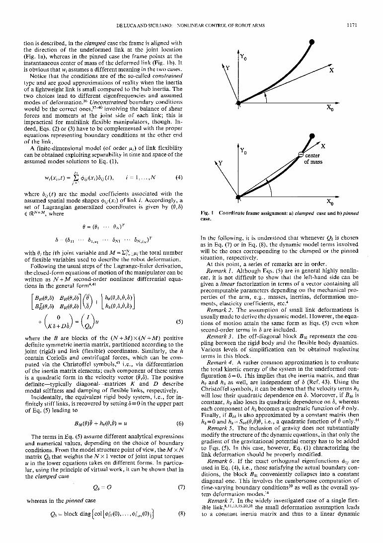
tion is described, in the clamped case the frame is aligned withthe direction of the undeformed link at the joint location(Fig. la), whereas in the pinned case the frame points at theinstantaneous center of mass of the deformed link (Fig. Ib). Itis obvious that w/ assumes a different meaning in the two cases.
Notice that the conditions are of the so-called constrainedtype and are good approximations of reality when the inertiaof a lightweight link is small compared to the hub inertia. Thetwo choices lead to different eigenfrequencies and assumedmodes of deformation.36 Unconstrained boundary conditionswould be the correct ones,37"40 involving the balance of shearforces and moments at the joint side of each link; this isimpractical for multilink flexible manipulators, though. In-deed, Eqs. (2) or (3) have to be complemented with the properequations representing boundary conditions at the other endof the link.
A finite-dimensional model (of order /*/) of link flexibilitycan be obtained exploiting separability in time and space of theassumed modes solutions to Eq. (1),
(4)
where 6//(0 are the modal coefficients associated with theassumed spatial mode shapes 0/y(JC/) of link /. Accordingly, aset of Lagrangian generalized coordinates is given by (0,6)€ (RN+M, where Fig. 1 Coordinate frame assignment: a) clamped case and b) pinned
with 0/ the /th joint variable and M = E/l i/*/ the total numberof flexible variables used to describe the robot deformation.
Following the usual steps of the Lagrange-Euler derivation,the closed-form equations of motion of the manipulator can bewritten as N + M second-order nonlinear differential equa-tions in the general form4'41
BeeOJ) B68(6,d) /0B$>(0,d) Bdd(6,d)\\d
0 \ / /+
K5 + D6 (5)
where the B are blocks of the (N + M) x (N + M) positivedefinite symmetric inertia matrix, partitioned according to thejoint (rigid) and link (flexible) coordinates. Similarly, the hcontain Coriolis and centrifugal forces, which can be com-puted via the Christoffel symbols,43 i.e., via differentiationof the inertia matrix elements; each component of these termsis a quadratic form in the velocity vector (0,6). The positivedefinite—typically diagonal—matrices K and D describemodal stiffness and damping of flexible links, respectively.
Incidentally, the equivalent rigid body system, i.e., for in-finitely stiff links, is recovered by setting 6 = 0 in the upper partof Eq. (5) leading to
(6)
The terms in Eq. (5) assume different analytical expressionsand numerical values, depending on the choice of boundaryconditions. From the model structure point of view, the MxNmatrix Qd that weights the TV x 1 vector of joint input torquesu in the lower equations takes on different forms. In particu-lar, using the principle of virtual work, it can be shown that inthe clamped case
65-0
whereas in the pinned case
Q5 = block
(7)
(8)
In the following, it is understood that whenever Qs is chosenas in Eq. (7) or in Eq. (8), the dynamic model terms involvedwill be the ones corresponding to the clamped or the pinnedsituation, respectively.
At this point, a series of remarks are in order.Remark 1. Although Eqs. (5) are in general highly nonlin-
ear, it is not difficult to show that the left-hand side can begiven a linear factorization in terms of a vector containing allprecomputable parameters depending on the mechanical pro-perties of the arm, e.g., masses, inertias, deformation mo-ments, elasticity coefficients, etc.4
Remark 2. The assumption of small link deformations isusually made to derive the dynamic model. However, the equa-tions of motion attain the same form as Eqs. (5) even whensecond-order terms in 6 are included.
Remarks. The off-diagonal block Bed represents the cou-pling between the rigid body and the flexible body dynamics.Various levels of simplification can be obtained neglectingterms in this block.
Remark 4. A rather common approximation is to evaluatethe total kinetic energy of the system in the undeformed con-figuration 6 = 0. This implies that the inertia matrix, and thushd and hd as well, are independent of 6 (Ref. 43). Using theChristoffel symbols, it can be shown that the velocity terms h8will lose their quadratic dependence on 6. Moreover, if Bd8 isconstant, he also loses its quadratic dependence on 6, whereaseach component of hd becomes a quadratic function of 0 only.Finally, if Bed is also approximated by a constant matrix thenhd = 0 and he = Sed(6,d)6, i.e., a quadratic function of 0 only.44
Remark 5. The inclusion of gravity does not substantiallymodify the structure of the dynamic equations, in that only thegradient of the gravitational potential energy has to be addedto Eqs. (5). In this case, however, Eq. (1) characterizing thelink deformation should be properly modified.
Remark 6. If the exact orthogonal eigenfunctions </>// areused in Eq. (4), i.e., those satisfying the actual boundary con-ditions, the block Bdd conveniently collapses into a constantdiagonal one. This involves the cumbersome computation oftime-vary ing boundary conditions39 as well as the overall sys-tem deformation modes.14
Remark 7. In the widely investigated case of a single flex-ible link,8'11'13'15'20'38 the small deformation assumption leadsto a constant inertia matrix and thus to a linear dynamic
1172 DE LUCA AND SICILIANO: NONLINEAR CONTROL OF ROBOT ARMS
model. Further, diagonalization of the inertia matrix can beachieved by means of a suitable coordinate transformation.40
If high rotational speeds are involved, however, the assumedmodes expansion may lead to incorrect results even for theone-link case.
Explicit expressions of the single terms in Eqs. (5) have beenrecently reported for particular flexible manipulators.4'14
For the purpose of control derivation, it is convenient toextract the flexible accelerations from Eqs. (5) as
6 = B88l[Q8u - (hs + Kd + Dd)-BQ66\ (9)
which, substituted into the upper part of Eqs. (5), gives
= Fu (10)
(U)
with
Notice that Eq. (10) describes the modification that takes placein the rigid body dynamics equation (6) due to the effects oflink flexibility.
Remark 8. The N x N matrix Bee - BebB^B^ has full rankas can be seen from the following identity:
Bee B6T D
I O-B^B? i O
B(
B8d.(12)
and the positive definiteness of the inertia matrix.Remark 9. Physical arguments can be used to show that the
NxN matrix F in Eq. (11) has full rank. For instance, con-sider the arm in an undeformed rest configuration, i.e.,d = d = Q, 6 = 0. If F were singular, a nonzero input torque uwould exist that yields # = 0 thus keeping the arm at rest; thisis clearly in contrast with mechanical intuition.
III. Inversion ControlTrajectory tracking in multi-input/multi-output nonlinear
systems is usually achieved by input-output inversion controltechniques.19 Once a meaningful output has been defined forthe system, a nonlinear state feedback is designed so that theresulting closed-loop system is transformed into a linear anddecoupled one, with the possible appearance of unobservableinternal dynamics. Under the assumption of stability of theresulting closed-loop system, exact reproduction of smoothdesired output trajectories is feasible.
In the robotic case, inversion can be applied directly to thesecond-order differential form of the mechanical system (5),defining the vector of joint variables 6 as the system output.Following the inversion algorithm, the output needs to bedifferentiated as many times as needed to have the input ex-plicitly appearing. Inspection of Eq. (10) suggests that thejoint accelerations 6 (the second time derivative of the output)are at the same differential level as the torque inputs u. There-fore, the so-called relative degree19 is uniform for all outputsand equal to two. Moreover, in view of Remarks 8 and 9, theinput u can be fully recovered from Eq. (10).
Let a denote a joint acceleration vector. Setting 0 = a inEq. (10) and solving for u yields the nonlinear feedback law
*»'>
with
ns = hs + K8 + D5
(13)
(14)
The closed-loop implementation of Eq. (13) requires the mea-surement of 0, 0, <5, and <5.
Remark 10. The matrix (Bee-B^B^B^Y^F is the socalled decoupling matrix19 of the system and is nonsingular.
so-
In the clamped case (Q8 = O) matrix F reduces to the iden-tity, and no inversion thereof is needed in Eq. (13). On theother hand, a computationally efficient expression for F"1
when Q8?± O, e.g., in the pinned case, is45
(15)
requiring only the inversion of an M x M matrix.Remark 11 . The advantage of evaluating F ~ l using Eq. (15)
exists in any case, but it is more striking when TV >M; in fact,when TV <M, the inversion of an M xM block is needed any-way in Eq. (11).
The control (13) transforms the closed-loop system into theinput-output linearized form
= a
8=
whereur=
(16)
iur (17)
(18)
is the well-known computed torque control46 for the equivalentrigid system (6).
At this point, one can recognize that in the clamped caseEq. (13) becomes
)a +he-
and Eqs. (16) and (17) simplify to
5= -B8~8l(Bd
T8a+n8)
(19)
(20)
(21)
Remark 12. It follows immediately from Eq. (19) that onlythe inversion of the M x M block on the diagonal of the inertiamatrix relative to the flexible variables is required for controllaw implementation in the clamped case. This computationalsaving was not present in previous works on inversion-basedcontrollers for flexible manipulators.21"23 Therefore, the com-plexity of this nonlinear feedback strategy increases only withthe number of flexible variables; in the limit, no inertia matrixinversion is required for the rigid case. Furthermore, if B88 isconstant (see Remark 6) its inverse can be conveniently com-puted offline.
To achieve tracking of a desired joint trajectory specified by0des(0» the control design is completed by choosing the newinput as
D(6fes - 0) des - 0) (22)
where KP>0 and KD>0 are feedback gain matrices that allowpole placement in the open left-hand complex half-plane forthe linear system (16). From Eq. (22) it is clear that the desiredtrajectory must be at least twice differentiable for having exactreproduction.
As mentioned, the applicability of the inversion controller(13) [or (19)] is based on the stability of the induced unobserv-able dynamics (17) [or (21)]. In the following, the discussion isconcentrated on the clamped case only. However, similar ar-guments could be used in the pinned case, just resulting inmore involved developments which are omitted.
The stability analysis can be carried out by studying theso-called zero dynamics associated with the system (20) and(21). This is obtained by constraining the output 0 of thesystem to be a constant, and without loss of generality, zero.Hence, from Eq. (21) we obtain
(23)
where all terms are evaluated for 0 = 0.

DE LUCA AND SICILIANO: NONLINEAR CONTROL OF ROBOT ARMS 1173
A sufficient condition that guarantees stability of the overallclosed-loop system is that the zero dynamics (23) are asymptot-ically stable.19 The following result holds.
Theorem. The state 6 = 6 = 0 is an asymptotically stableequilibrium point for the system (23). D
Proof. Applying the Lyapunov direct method, define theenergy-based candidate function
V = V2 dTKd + Vi dTB88d
Time differentiation of Eq. (24) gives
V = dTKd + dTB88d + 1/2 5TB88d
and substitution of Eq. (23) into Eq. (25) yields
K= -dT(hd + Dd) + l/2dTB88d
(24)
(25)
(26)
Observe that for the velocity dependent term h8 there existsalways a factorization h8 = S885 such that the matrix B88 - 2S88is skew symmetric.41 As a consequence, Eq. (26) reduces to
V = -6r.D6<0 (27)
To show asymptotic stability, note that F=0 if and only if6 = 0. In this case, the system dynamics (23) becomes6= — B f t l K d , which implies that the largest invariant set inF=0 is 6 = 6 = 0. Invoking LaSalle invariance set theorem,48
the result follows. DRemark 13. The foregoing result, together with the choice
equation (22), also permits the conclusion that the closed-loopsystem is asymptotically stable under the inversion control law(19) in the trajectory tracking case (07*0). To understand thisfact, consider the simpler case of an inertia matrix independentof 6 (see Remark 4). When 0 = 0des(0 is imposed by the control(19) and (22), the flexible variables satisfy the following lineartime-varying equation
where
is a known function of time, and
(28)
, 0des)] (29)
(30)
(31)
Then, as long as all time-varying functions are bounded, sta-bility is ensured even during trajectory tracking.
Remark 14. From Eq. (27), the rate of asymptotic conver-gence to zero of the flexible variables is established by the armdamping matrix D, generally resulting in a poorly dampedbehavior. This may be satisfactory during the large maneuver-ing phase of the manipulator, but it represents a major concernat the final destination. The standard remedy to this limitationis to resort to an active linear stabilizer for the deflectionvariables, designed for a linearized version of the systemaround the final configuration. It is convenient, indeed, tosuperimpose such a stabilizing control on the nonlinear one(19) and (22); in this way the synthesis can be advantageouslyperformed on the system (20) and (21), which is linear in theinput-output behavior, rather than on the original nonlinearsystem.23 Alternatively, damping can be increased in a passivefashion by a mechanical treatment of the lightweight structure,e.g., attaching thin layers of viscoelastic material to the linksurfaces.49
In the preceding derivation of the inversion-based control, itwas assumed that full state feedback is available. The jointpositions and velocities are measured via ordinary encodersand tachometers mounted on the actuators. For measuring
link deflection, different apparatus can be used ranging fromstrain gauges,9 to accelerometers,12 or optical devices.11
In spite of the availability of direct measurements of linkflexibility, it may be convenient to avoid their use within thecomputation of the nonlinear part of the controller. The joint-based approach naturally lends itself to a cheap implementa-tion in terms of joint variable measures only. In fact, one canpreserve the robust linear feedback (22) and add a feedforwardaction to compensate for the nominal nonlinear terms. Specif-ically, when a twice differentiable joint trajectory Bdcs(t) hasbeen assigned, the forward integration of the flexible dynamics
6 = -
(32)
from initial conditions 6(0) = 60, 6(0) = 50, provides the associ-ated time evolution 6des(0> ^des(0 of the flexible variables.Hence, evaluation of the nonlinearities in Eq. (19) along thecomputed state trajectory gives a control law in the form
u = udes(t) + KP(t)(Odes-0) + KD(t)(Odes-8)
where Eq. (22) has been used, and
(33)
KD
(34)
(35)
(36)
Remark 15. The initial conditions for numerical integrationof Eq. (32) are typically 60 = 60 = 0, corresponding to the unde-formed rest configuration for the arm. Since the dynamics (32)are asymptotically stable, as just demonstrated, the evolution^des(0> ^des(0 generated from any initial condition will bebounded in response to a Odes(t) with bounded second deriva-tive. Indeed, the initial condition should match the actual ini-tial deformation of the arm, otherwise the computed feedfor-ward term (34) would not be the correct one. However, forpersistent reference trajectories, an initial mismatch leads totracking errors limited to the transient phase, since 6des(0 any-how decays toward the natural steady-state evolution.
Remark 16. An even simpler implementation of Eq. (33) is
U = (37)
with constant feedback matrices. This type of control law hasbeen tested experimentally on a two-link manipulator with aflexible forearm.50
IV. Case StudyThe inversion-based nonlinear control laws presented earlier
have been tested in simulation on a very light two-link planarflexible arm (TV = 2), assuming two clamped mode shapes foreach link (^ = /*2 = 2, implying M = 4) (Fig. 2). This reduced-order model is sufficient to encompass the relevant flexibilityoccurring in practical experimental control of lightweight ma-nipulators with limited bandwidth actuators.The physicalparameters characterizing the arm are the following: uniformdensity pl = p2 = 0.2 kg/m; (EI^ = (£7)2 = 1 N/m2; link lengths/! = /2 = 0.5 m; link masses ^71 = m2 = 0.1 kg; tip payload massmp =0.1 kg; mass of second hub mh2= 1 kg; inertias of linksabout relative joint axes J0\ = J02 = 0.0083 kg m2; hub inertiasJh\ = Jh2 = 0-1 kg m2; and tip payload inertia Jp = 0.0005 kg m2.

1174 DE LUCA AND SICILIANO: NONLINEAR CONTROL OF ROBOT ARMS
Fig. 2 Planar two-link flexible manipulator.
The first two natural eigenfrequencies of the links are
First link: /„ = 0.48 Hz, /12 = 1.80 Hz
Second link: /21 = 2.18Hz, /22 = 15.91 Hz
which allow the computation of the stiffness matrix K as
Ar = diag{AT/)=diag{0.91, 12.74, 18.73,999.88) kg/s2
The modal damping matrix is chosen as D = diag{0.lV^ ) .The complete dynamic model of the system is reported inRef. 4.
The desired trajectory has been chosen as a sinusoidal pro-file with zero initial and final velocities and accelerations,
0<ta.iC) = «ta,/(0) + I t - ^- sin(360 deg ̂Jou \ -i ,
1 = 1,2 (38)
where T is the traveling time. The closed-loop dynamic equa-tions have been integrated with a fourth-order Runge-Kuttamethod at 1-ms sampling time.
First, the input-output feedback linearizing controller (19)and (22) with T = 8 s and
0des,i(8) = 45 deg
has been simulated using
(39)
(40)
This choice corresponds to placing the poles of the resultinglinear system (20) and (22) both at - 1 for the first joint, andboth at -2 for the second joint; in general, it was found thatwhenever system nonlinearities are canceled through inversionfeedback, the design of suitable control gains is not a criticalissue. The results in Fig. 3 indicate that the first joint evolutionreproduces the desired trajectory, and the second joint is prac-tically held fixed, with a maximum error of 0.23 deg. The tiperror is limited to 1.6 cm along the y component; this error iscomputed as the deviation between the tip trajectory resultingfrom Eqs. (38) and (39)—as if the links were rigid—and theactual trajectory. The required joint input torques are indeedvery small due to the lightweight nature of the arm.
The same control law, with gains as in Eq. (40), has beenused for tracking a slewing motion on both joints specified by
Satisfactory performance is obtained also in this case (Fig. 4),with a maximum tracking error of 0.33 deg on the second jointand a maximum tip error of ~ 2 cm on both Cartesian coordi-nates. The torque profiles are similar to the preceding ones,with a slight increase for the second joint.
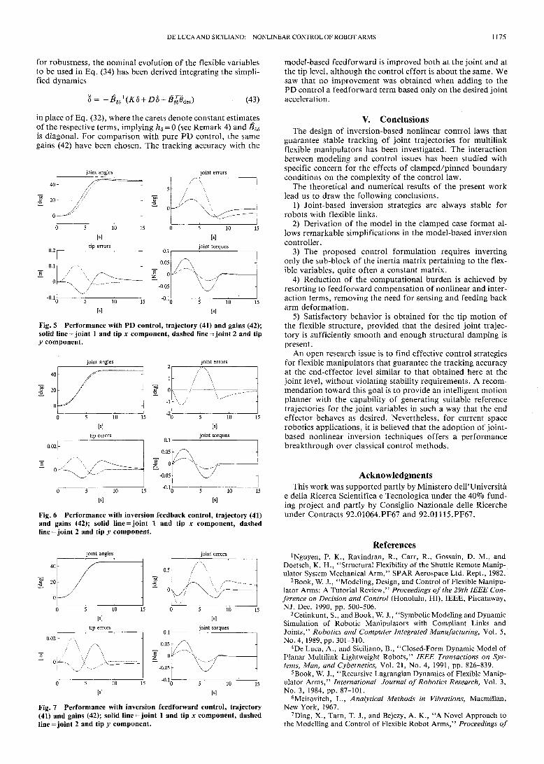
Next, a linear joint feedback proportional-derivative (PD)controller has been applied for the slewing motion (40). In thiscase, the gains have been tuned down to
KP = diag{ 1, 0.04), KD = diag{2, 0.4) (42)
to avoid numerical instability. In fact, since the nonlineardynamic couplings during motion are not compensated, largererrors are induced which would result in excessive inputtorques applied to the flexible system. In Fig. 5, the resultingjoint trajectories display a transient lag, an overshoot, and alonger settling time, which are typical of PD controllers. Themaximum tracking error is 7.8 deg on the second joint, andconsequently a maximum tip error of 11 cm is obtained.
To further compare the performance of the proposed non-linear control law with a linear PD control, the reduced gains(42) have been used also for the control law (19) and (22). Theresults in Fig. 6 show that nonlinear compensation reduces thejoint tracking errors by a factor of four, even with the samegains for the linear control part. Notice that the input torquesin Figs. 4-6 are of comparable magnitude. This in turn meansthat the feedback gains in the inversion controller can be con-veniently increased to reduce tracking errors, without affectingthe overall control effort.
Finally, the results achieved with the computationallycheaper feedforward strategy (37) are shown in Fig. 7. To test
joint angles joint errors
40
I 2°
0
0.5
10 15
tip errors
0.02
0
(
^Oc ———) 5 10 1
W
0.1
0.05
-0.05
5 10 15
Wjoint torques
5 10 15
W
Fig. 3 Performance with inversion feedback control, trajectory (39)and gains (40); solid line = joint 1 and tip x component, dashedline = joint 2 and tip y component.
I 20
joint angles
5 10
Mtip errors
joint errors
0.5
() 5 10 1
Mjoint torques
0des,/(0) = 0 deg, = 45 deg, / = 1, 2 (41)
Fig. 4 Performance with inversion feedback control, trajectory (41)and gains (40); solid line = joint 1 and tip x component, dashedline = joint 2 and tip y component.
DE LUCA AND SICILIANO: NONLINEAR CONTROL OF ROBOT ARMS 1175
for robustness, the nominal evolution of the flexible variablesto be used in Eq. (34) has been derived integrating the simpli-fied dynamics
(43)
in place of Eq. (32), where the carets denote constant estimatesof the respective terms, implying hd = 0 (see Remark 4) and Bd8is diagonal. For comparison with pure PD control, the samegains (42) have been chosen. The tracking accuracy with the
joint angles joint errors
Fig. 5 Performance with PD control, trajectory (41) and gains (42);solid line = joint 1 and tip x component, dashed line = joint 2 and tipy component.
joint angles joint errors
Fig. 6 Performance with inversion feedback control, trajectory (41)and gains (42); solid line = joint 1 and tip x component, dashedline = joint 2 and tip y component.
joint angle: joint errors
Fig. 7 Performance with inversion feedforward control, trajectory(41) and gains (42); solid line = joint 1 and tip x component, dashedline=joint 2 and tip y component.
model-based feedforward is improved both at the joint and atthe tip level, although the control effort is about the same. Wesaw that no improvement was obtained when adding to thePD control a feedforward term based only on the desired jointacceleration.
V. ConclusionsThe design of inversion-based nonlinear control laws that
guarantee stable tracking of joint trajectories for multilinkflexible manipulators has been investigated. The interactionbetween modeling and control issues has been studied withspecific concern for the effects of clamped/pinned boundaryconditions on the complexity of the control law.
The theoretical and numerical results of the present worklead us to draw the following conclusions.
1) Joint-based inversion strategies are always stable forrobots with flexible links.
2) Derivation of the model in the clamped case format al-lows remarkable simplifications in the model-based inversioncontroller.
3) The proposed control formulation requires invertingonly the sub-block of the inertia matrix pertaining to the flex-ible variables, quite often a constant matrix.
4) Reduction of the computational burden is achieved byresorting to feedforward compensation of nonlinear and inter-action terms, removing the need for sensing and feeding backarm deformation.
5) Satisfactory behavior is obtained for the tip motion ofthe flexible structure, provided that the desired joint trajec-tory is sufficiently smooth and enough structural damping ispresent.
An open research issue is to find effective control strategiesfor flexible manipulators that guarantee the tracking accuracyat the end-effector level similar to that obtained here at thejoint level, without violating stability requirements. A recom-mendation toward this goal is to provide an intelligent motionplanner with the capability of generating suitable referencetrajectories for the joint variables in such a way that the endeffector behaves as desired. Nevertheless, for current spacerobotics applications, it is believed that the adoption of joint-based nonlinear inversion techniques offers a performancebreakthrough over classical control methods.
AcknowledgmentsThis work was supported partly by Ministero dell'Universita
e della Ricerca Scientifica e Tecnologica under the 40% fund-ing project and partly by Consiglio Nazionale delle Ricercheunder Contracts 92.01064.PF67 and 92.01115.PF67.
References^guyen, P. K., Ravindran, R., Carr, R., Gossain, D. M., and
Doetsch, K. H., "Structural Flexibility of the Shuttle Remote Manip-ulator System Mechanical Arm," SPAR Aerospace Ltd. Rept., 1982.
2Book, W. J., "Modeling, Design, and Control of Flexible Manipu-lator Arms: A Tutorial Review," Proceedings of the 29th IEEE Con-ference on Decision and Control (Honolulu, HI), IEEE, Piscataway,NJ, Dec. 1990, pp. 500-506.
3Cetinkunt, S., and Book, W. J., "Symbolic Modeling and DynamicSimulation of Robotic Manipulators with Compliant Links andJoints," Robotics and Computer Integrated Manufacturing, Vol. 5,No. 4, 1989, pp. 301-310.
4De Luca, A., and Siciliano, B., "Closed-Form Dynamic Model ofPlanar Multilink Lightweight Robots," IEEE Transactions on Sys-tems, Man, and Cybernetics, Vol. 21, No. 4, 1991, pp. 826-839.
5Book, W. J., "Recursive Lagrangian Dynamics of Flexible Manip-ulator Arms," International Journal of Robotics Research, Vol. 3,No. 3, 1984, pp. 87-101.
6Meirovitch, L., Analytical Methods in Vibrations, Macmillan,New York, 1967.
7Ding, X., Tarn, T. J., and Bejczy, A. K., "A Novel Approach tothe Modelling and Control of Flexible Robot Arms," Proceedings of
1176 DE LUCA AND SICILIANO: NONLINEAR CONTROL OF ROBOT ARMS
the 27th IEEE Conference on Decision and Control (Austin, TX),IEEE, Piscataway, NJ, Dec. 1988, pp. 52-57.
8Hastings, G. G., and Book, W. J., "A Linear Dynamic Model forFlexible Robotic Manipulators," IEEE Control Systems Magazine,Vol. 7, No. 1, 1987, pp. 61-64.
9Usoro, P. B., Nadira, R., and Mahil, S. S., "A Finite-ElementLagrangian Approach to Modeling Lightweight Flexible Manipula-tors," ASME Journal of Dynamic Systems, Measurement, and Con-trol, Vol. 108, No. 3, 1986, pp. 198-205.
10Tomei, P., and Tornambe, A., "Approximate Modeling of Ro-bots Having Elastic Links," IEEE Transactions on Systems, Man, andCybernetics, Vol. 18, No. 5, 1988, pp. 831-840.
11 Cannon, R. H., and Schmitz, E., "Initial Experiments on theEnd-Point Control of a Flexible One-Link Robot," InternationalJournal of Robotics Research, Vol. 3, No. 3, 1984, pp. 62-75.
12Chalhoub, N. G., and Ulsoy, A. G., "Control of a Flexible RobotArm: Experimental and Theoretical Results," ASME Journal of Dy-namic Systems, Measurement, and Control, Vol. 109, No. 4, 1987, pp.299-309.
13Sakawa, Y., Matsuno, F., and Fukushima, S., "Modeling andFeedback Control of a Flexible Arm," Journal of Robotic Systems,Vol. 2, No. 4, 1985, pp. 453-472.
14Oakley, C. M., and Cannon, R. H.,"Anatomy of an Experimen-tal Two-Link Flexible Manipulator Under End-Point Control," Pro-ceedings of the 29th IEEE Conference on Decision and Control (Hon-olulu, HI), Dec. 1990, pp. 507-513.
15Yuan, B.-S., Book, W. J., and Siciliano, B., "Direct AdaptiveControl of a One-Link Flexible Arm With Tracking," Journal ofRobotic Systems, Vol. 6, No. 6, 1989, pp. 663-680.
16Siciliano, B., and Book, W. J., "A Singular Perturbation Ap-proach to Control of Lightweight Flexible Manipulators," Interna-tional Journal of Robotics Research, Vol. 7, No. 4, 1988, pp. 79-90.
17Khorrami, F., and Ozgiiner, U., "Perturbation Methods in Con-trol of Flexible Link Manipulators," Proceedings of the 1988 IEEEInternational Conference on Robotics and Automation (Philadelphia,PA), IEEE, Piscataway, NJ, April 1988, pp. 310-315.
18Siciliano, B., Prasad, J. V. R., and Calise, A. J., "Output Feed-back Two-Time Scale Control of Multilink Flexible Arms," ASMEJournal of Dynamic Systems, Measurement, and Control, Vol. 114,No. 1, 1992, pp. 70-77.
19Isidori, A., Nonlinear Control Systems, 2nd edition, Springer-Verlag, Berlin, Germany, 1989.
20De Luca, A., and Siciliano, B., "Joint-Based Control of a Non-linear Model of a Flexible Arm," Proceedings of the 1988 AmericanControl Conference (Atlanta, GA), IEEE, Piscataway, NJ, June1988, pp. 935-940.
21Singh, S. N., and Schy, A. A., "Control of Elastic Robotic Sys-tems by Nonlinear Inversion and Modal Damping, "ASME Journal ofDynamic Systems, Measurement, and Control, Vol. 108, No. 3, 1986,pp. 180-189.
22Singh, S. N., and Schy, A. A., "Elastic Robot Control: NonlinearInversion arid Linear Stabilization," IEEE Transactions on Aerospaceand Electronic Systems, Vol. 22, No.. 4, 1986, pp. 340-348.
23Das, A., and Singh, S. N., "Dual Mode Control of an ElasticRobotic Arm: Nonlinear Inversion and Stabilization by Pole Assign-ment," International Journal of Systems Science, Vol. 21, No. 7,1990, pp. 1185-1204.
24Monaco, S., Normand-Cyrot, D., and Stornelli, S., "SampledNonlinear Control for Large Angle Manoeuvers of Flexible Space-craft," European Space Agency SP-255, Noordwijk, The Nether-lands, 1986.
25Dwyer, T. A. W., "Exact Nonlinear Control of Large Angle Ro-tation Maneuvers," IEEE Transactions on Automatic Control, Vol.29, No. 9, 1984, pp. 769-774.
26De Luca, A., and Siciliano, B., "Trajectory Control of a Non-Linear One-Link Flexible Arm," International Journal of Control,Vol. 50, No. 11, 1989, pp. 1699-1716.
27Madhavan, S. K., and Singh, S. N., "Inverse Trajectory Controland Zero Dynamics Sensitivity of an Elastic Manipulator," Proceed-ings of the 1991 American Control Conference (Boston, MA), IEEE,Piscataway, NJ, June 1991, pp. 1879-1884.
28Franklin, G. F., Powell, J. D., and Emami-Naeini, A., FeedbackControl of Dynamic Systems, Addison-Wesley, Reading, MA, 1986.
29Joshi, S. M., "Robustness Properties of Collocated Controllersfor Flexible Spacecraft," Journal of Guidance, Control, and Dynam-
ics, Vol. 9, No. 1, 1986, pp. 85-91.30Murotsu, Y, Okubo, H., and Terui, F., "Low-Authority Control
of Large Space Structures by Using a Tendon Control System," Jour-nal of Guidance, Control, and Dynamics, Vol. 12, No. 2, 1989, pp.264-272.
31De Luca, A., Lucibello, P., and Ulivi, G., "Inversion Techniquesfor Trajectory Control of Flexible Robot Arms," Journal of RoboticSystems, Vol. 6, No. 4, 1989, pp. 325-344.
32Pfeiffer, F., "A Feedforward Decoupling Concept for the Controlof Elastic Robots," Journal of Robotic Systems, Vol. 6, No. 4, 1989,pp. 407-416.
33De Luca, A., Lanari, L., and Ulivi, G., "End-Effector TrajectoryTracking in Flexible Arms: Comparison of Approaches Based on Reg-ulation Theory," Advanced Robot Control, edited by C. Canudas deWit, Lecture Notes in Control and Information Sciences, Vol. 162,Springer-Verlag, Berlin, Germany, 1991, pp. 190-206.
34Bayo, E., Serna, M. A., Papadopoulus, P., and Stubbe, J., "In-verse Dynamics and Kinematics of Multi-Link Elastic Robots: AnIterative Frequency Domain Approach," International Journal ofRobotics Research, Vol. 8, No. 6, 1989, pp. 49-62.
35Cetinkunt, S., and Book, W. J., "Performance Limitations ofJoint Variable-Feedback Controllers Due to Manipulator StructuralFlexibility," IEEE Transactions on Robotics and Automation, Vol. 6,No. 2, 1990, pp. 219-231.
36Cetinkunt, S., and Yu, W. L., "Closed-Loop Behavior of a Feed-back-Controlled Flexible Arm: A Comparative Study," InternationalJournal of Robotics Research, Vol. 10, No. 3, 1991, pp. 263-275.
37Hablani, H. B., "Constrained and Unconstrained Modes: SomeModeling Aspects of Flexible Spacecraft," Journal of Guidance, Con-trol, and Dynamics, Vol. 5, No. 2, 1982, pp. 164-173.
38Barbieri, E., and Ozgiiner, U., "Unconstrained and ConstrainedMode Expansions for a Flexible Slewing Link," ASME Journal ofDynamic Systems, Measurement, and Control, Vol. 110, No. 4, 1988,pp. 416-421.
39Low, K. H., "Solution Schemes for the System Equations ofFlexible Robots," Journal of Robotic Systems, Vol. 6, No. 4, 1989,pp. 383-405.
40Bellezza, F., Lanari, L., and Ulivi, G., "Exact Modeling of theSlewing Flexible Link," Proceedings of the 1990 IEEE InternationalConference on Robotics and Automation (Cincinnati, OH), IEEE,Piscataway, NJ, May 1990, pp. 734-739.
41 De Luca, A., and Siciliano, B., "Issues in Modelling Techniquesfor Control of Robotic Manipulators with Structural Flexibility,"Proceedings of the 13th IMACS World Congress on Computation andApplied Mathematics, Criterion Press, Dublin, Ireland, July 1991,pp. 1121-1122.
42Sakawa, Y, and Luo, Z. H., "Modeling and Control of CoupledBending and Torsional Vibrations of Flexible Beams," IEEE Transac-tions on Automatic Control, Vol. 34, No. 9, 1989, pp. 970-977.
43Goldstein, H., Classical Mechanics, 2nd edition, Addison-Wesley, Reading, MA, 1980.
44De Luca, A., and Siciliano, B., "Relevance of Dynamic Models inAnalysis and Synthesis of Control Laws for Flexible Manipulators,"Robotics and Flexible Manufacturing Systems, edited by S. G. Tzafes-tas and J. C. Gentina, Elsevier, Amsterdam, The Netherlands, 1992,pp.161-168.
45Kailath, T., Linear Systems, Prentice-Hall, Englewood Cliffs, NJ,1980.
46Craig, J. J., Introduction to Robotics: Mechanics and Control,2nd edition, Addison-Wesley, Reading, MA, 1989.
47Takegaki, M., and Arimoto, S., "A New Feedback Method forDynamic Control of Manipulators," ASME Journal of Dynamic Sys-tems, Measurement, and Control, Vol. 103, No. 1, 1981, pp. 119-125.
48Hahn, W., Stability of Motion, Springer Verlag, Berlin, Germany,1967.
49Alberts, T. E., "Augmenting the Control of a Flexible Manip-ulator with Passive Mechanical Damping," Ph.D. Thesis, School ofMechanical Engineering, Georgia Institute of Technology, Atlanta,GA, 1986.
50De Luca, A., Lanari, L., Lucibello, P., Panzieri, S., and Ulivi, G.,"Control Experiments on a Two-Link Robot With a Flexible Fore-arm," Proceedings of the 29th IEEE Conference on Decision andControl (Honolulu, HI), IEEE, Piscataway, NJ, Dec. 1990, pp. 520-527.