inverter split type air conditioner...
TRANSCRIPT

INVERTER SPLIT TYPEAIR CONDITIONER (50Hz)DUCT TYPE
CONTENTS
SPECIFICATIONS . . . . . . . . . . . . . . . . . . . .1DIMENSIONS. . . . . . . . . . . . . . . . . . . . . . . .3
CIRCUIT DIAGRAM. . . . . 5REFRIGERANT SYSTEM DIAGRAM
. . . . . . . . . . . . . . . . . . .6
ERROR CONTENTS
. . . . . . .8INDOOR PCB CIRCUIT DIAGRAM. . . .14OUTDOOR PCB CIRCUIT DIAGRAM
. . . . . . . . . . . . . . . . .16PARTS (INDOOR UNIT) . . . . . . . . . . . . . . 18PARTS (OUTDOOR UNIT) . . . . . . . . . . . .21ACCESSORIES. . . . . . . . . . . . . . . . . . . . . 24
Indoor unit Outdoor unit
ARYF12LALUARYF12LALUARYF12LALUARYF12LALUARYF14LALUARYF14LALUARYF14LALUARYF14LALUARYF18LALUARYF18LALUARYF18LALUARYF18LALUARYF18LBLUARYF18LBLU
AOYA12LACLAOYA12LALLAOYB12LACLAOYB12LALLAOYA14LACLAOYA14LALLAOYB14LACLAOYB14LALLAOYA18LACLAOYA18LALLAOYB18LACLAOYB18LALLAOYA18LALLAOYB18LALL

2009.07.07 1
SPECIFICATIONS
TYPE Inverter Cool & Heat
INDOOR UNIT ARYF12LALU
OUTDOOR UNIT AOYA12LA_L
COOLING CAPACITY 3.50 kW
HEATING CAPACITY 4.10 kW
POWER SOURCE 230 V
FREQUENCY 50 Hz
RUNNINGCURRENT
Cooling 4.6 A
Heating 4.9 A
INPUT WATTSCooling 1.05 kW
Heating 1.11 kW
E.E.R.Cooling 3.33 kW/kW
Heating 3.69 kW/kW
STARTING CURRENT 4.9 A
MOISTURE REMOVAL 1.3 L/hr
MFH-24RVL
880 r.p.m.
780 r.p.m.
720 r.p.m.
620 r.p.m.
700 r.p.m.
MFE-18ROM
Discrimination
Discrimination
High
FAN SPEED
INDOORUNIT Med
Low
OUTDOORUNIT
Heating
770 r.p.m.Cooling
ELECTRICAL DATA
Note : The above list shows values at the external static pressureof 0Pa, setting the fan speed high notch. (indoor unit)
Note : The above list shows values at the external static pressureof 0Pa, setting the fan speed high notch. (indoor unit)
AIR FLOW
INDOOR UNIT
720 m3/h
OUTDOORUNIT
1,780 m3/h
High
Med 630 m3/h
Low
Quiet
560 m3/h
480 m3/h
Cooling
Heating 1,630 m3/h
Inverter Cool & Heat
ARYF18L_LU
AOYA18LA_L
5.20 kW
6.00 kW
230 V
50 Hz
7.1 A
7.3 A
1.62 kW
1.66 kW
3.21 kW/kW
3.61 kW/kW
7.7 A
2.0 L/hr
MFH-24RVL
1,040 r.p.m.
950 r.p.m.
840 r.p.m.
740 r.p.m.
820 r.p.m.
MFE-18ROM
860 r.p.m.
820 m3/h
2,000 m3/h
720 m3/h
610 m3/h
550 m3/h
1,910 m3/h
Inverter Cool & Heat
ARYF14LALU
AOYA14LA_L
4.30 kW
5.00 kW
230 V
50 Hz
5.8 A
5.9 A
1.33 kW
1.34 kW
3.21 kW/kW
3.71 kW/kW
5.9 A
MAXIMUM CURRENT 10.0 A 12.5 A12.5 A
1.5 L/hr
MFH-24RVL
1,040 r.p.m.
950 r.p.m.
840 r.p.m.
740 r.p.m.
750 r.p.m.
MFE-18ROM
820 r.p.m.
870 m3/h
1,910 m3/h
770 m3/h
670 m3/h
580 m3/h
1,740 m3/h
Note : The above list shows values at the external static pressureof 0Pa, setting the fan speed high notch. (indoor unit)
Quiet
When you dismantle indoor units which are installed,take care not to make parts fall down, especially motors.
AOYB12LA_L
4.9 A
5.1 A
1.11 kW
1.17 kW
3.15 kW/kW
3.50 kW/kW
AOYB18LA_L
7.4 A
7.7 A
1.70 kW
1.75 kW
3.06 kW/kW
3.43 kW/kW
AOYB14LA_L
6.2 A
6.2 A
1.41 kW
1.42 kW
3.05 kW/kW
3.52 kW/kW

2009.07.07 2
INDOOR UNIT ARYF12LALU
OUTDOOR UNIT AOY_12LA_L
COMPRESSOR TYPE Hermetic type, 4 poles, DC motor, Twin Rotary
DISCRIMINATION
WEIGHT (with oil)
DA130AIF-25NA
9.6 kg
STANDARD REFRIGERANT
REFRIGERANT TYPE R410A R410A R410A
1,150 g
DIMENSIONS Indoor unit
H x W x D Outdoor unit
WEIGHT Indoor unit
Gross / Net Outdoor unit
COMPRESSOR AND REFRIGERANT
MEASUREMENT
Pipe Length 15 m 1,150 g
FULL CHARGE 20 m 1,250 g
25 m 1,350 g
MAXIMUM PIPE HEIGHT 15 m
ADDITIONAL CHARGE 20 g/m
NOISE LEVELHigh speed 32 dB
INDOOR UNITMed speed 30 dB
Low speed
Quiet
Cooling
Heating
28 dB
26 dB
47 dB
48 dB
ARYF14LALU
AOY_14LA_L
1,250 g
217 x 953 x 595 mm
578 x 790 x 300 mm
27 kg / 23 kg
44 kg / 40 kg
1,250 g
1,350 g
1,450 g
15 m
20 g/m
33 dB
31 dB
29 dB
27 dB
49 dB
49 dB
ARYF18L_LU
AOY_18LA_L
1,250 g
1,250 g
1,350 g
1,450 g
15 m
20 g/m
33 dB
31 dB
29 dB
27 dB
50 dB
50 dBOUTDOOR UNIT
Note : Static pressure : 0PaDuct length : Inlet 1m, Outlet 2m (indoor uit)
When you dismantle indoor units which are installed,take care not to make parts fall down, especially motors.

DIMENSIONS
Unit : mm
Drain pipe diametersInside : 21.5 mmOutside : 26.0 mm
INDOOR UNIT
886
850
953
920600
390
150
217
605
57520
2008.05.02 3
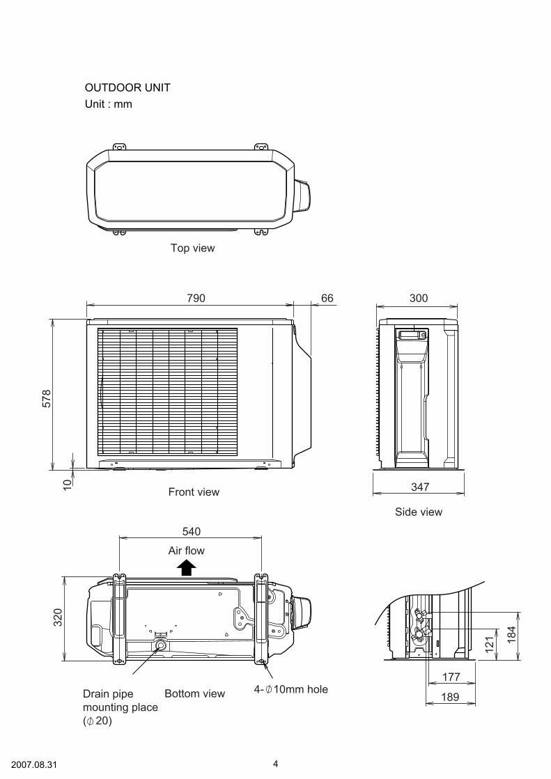
OUTDOOR UNITUnit : mm
Top view
Front view
Side view
Bottom viewDrain pipemounting place( 20)
189
177
347
540
30066790
121
578
320
10
184
4- 10mm hole
Air flow
2007.08.31 4

REFRIGERANT SYSTEM DIAGRAM
OUTDOOR UNIT INDOOR UNIT
2008.08.01 5
S trainerStrainer
4-Wayvalve
2-Wayvalve
3-Wayvalve
Muffler
Muffler
E xpansionvalve
C ompressor
Accumulator
Heat exchangerHeat exchanger
Cool<Refrigerant direction>
Heat
: THERMISTOR (COMPRESSOR) : THERMISTOR (PIPE): THERMISTOR (ROOM): THERMISTOR (DISCHARGE)
: THERMISTOR (HEAT EXCHANGER MED): THERMISTOR (HEAT EXCHANGER OUT): THERMISTOR (OUTDOOR AIR)
<Refrigerant pipe diameter>
ARYF12LALU / AOYA12LA_L Liquid : 1/4" (6.35 mm) Gas : 3/8" (9.52 mm)
ARYF14LALU / AOYA14LA_LARYF18LALU / AOYA18LA_L Liquid : 1/4" (6.35 mm) Gas : 1/2" (12.70 mm)

BLACK
RED
WHITEYELLOWBLUE
REDWHITEBLACK
REDBROWNBLUEORANGEYELLOWWHITE
BLACK
BLACK
BLACK
BLACK
BLACK
BLACKBLACK
WHITE
WHITE
RED
BROWNBROWN
BROWNBROWN
BLACKBLACK
WHITERED
YE
LLO
W
YE
LLO
W
GR
EE
NBLA
CK
BLA
CK
BLA
CK
123456
123456
123456
123456
123
123
123
123
12
12
12
12
1234
1234
1212
123
123
RED
WHITE
BLACK
CN71
CN73
CN72
CN70
W4
W2
W1
W3
W11W10
CN40
CN801
W7W8W9
CN30 4-WAY VALVE4WV
PMV
F M
S (S)C (T)
R (R)
FAN MOTOR
EXPANSION VALVE
COMPRESSORC M
REACTOR
THERMISTOR ( PIPE TEMPE. )
THERMISTOR ( DISCHARGE PIPE TEMP. )
THERMISTOR ( COMPRESSOR TEMP. )
THERMISTOR ( PIPE - MID. TEMP. )
THERMISTOR ( OUTDOOR TEMP. )
FUSE 250V 5A
TERMINAL
POWER SOURCE
2( N )
1 3 L N
FUSE 250V 20A
CONTROLLER PCB ASSY
2008.07.31 6
INDOOR UNITARYF12, 14, 18LALU
OUTDOOR UNIT
CIRCUIT DIAGRAM
GRAYGRAY
BLACKBLACK
WHITEBLACK
RED
WHITEBLACK
RED
GR
AYG
RAY
GR
AYG
RAY
GR
AYG
RAY
GR
AYG
RAY
GR
AYG
RAY
GR
AY
GR
EE
N
GR
EE
NGR
EE
N/ Y
ELL
OW
YELLOWBROWN
WHITEBLACK
RED
1234567
123456
123
123
12
12
123456
123456
1234567
1234567
8 8
12345
12345
123
12
1 2 3 4 5 6 7 81 2 3 4 5 6 7 8
1 2 3 4 5 6 7 81 2 3 4 5 6 7 8
1 2 31 2 3
1 2 3 1 2
1 2 31 2 3
1 2 1 21 2 1 2 1 2
CN12
CN11
CN9
CN10CN4 CN1
CN6
CN14
CN13
CN3
CN5 CN7 CN8
CN104 CN101
CN102 CN103
CN105
CN106
E101 E102
W105W102W101
TERMINAL
TERMINAL
TO REMOTE CONTROL
FAN MOTOR
F M
TERMISTOR( PIPE TEMP. )TERMISTOR( ROOM TEMP. )
1 2 3
1 2 3
POWER SUPPLYPCB ASSEMBLY
CONTROLLERPCB ASSEMBLY

GRAYGRAY
BLACKBLACK
REDWHITEBLACK
REDWHITEBLACK
YELLOWBROWN
WHITEBLACK
RED
GR
AYG
RAY
GR
AYG
RAY
GR
AYG
RAY
GR
AYG
RAY
GR
AYG
RAY
GR
AY
1 2 3 4 5 6 7 8 1 2 31 2 3 4 5 6 7 8 1 2 3
1 2 3 4 5 6 7 8 1 2 31 2 3 4 5 6 7 8 1 2 3
1 2 3 1 2 1 2
12
1 2 1 221 2 1 2
1
1234567
123
123
12
123
12345
12345
123
12
123456
123456
1234567
1234567
8 8GR
EE
N/ Y
ELL
OW
GR
EE
N
GR
EE
N
CN101W105W102W101
CN108CN103CN102
CN104
E101 E102
CN
105
CN
106
CN4 CN1
CN5 CN7 CN8C
N12
CN
11C
N9
CN
10
CN
6C
N14
CN
13C
N3
TERMISTOR( PIPE TEMP. )
TERMISTOR( ROOM TEMP. )
TERMINAL
TERMINALF101
1 2 3
1 2 3
TO OUTDOOR UNIT
TO REMOTE CONTROL
FUSE3.15A 250VF M
FAN MOTOR
CONTROLLERPCB ASSEMBLY
POWER SUPPLYPCB ASSEMBLY
456
12345
CN
2
2009.01.13 7
INDOOR UNITARYF18LBLU

PCB Circuit Diagrams not available at time of publication

Troubleshooting at the remote control LCDThis is possible only on the wired remote control.
SELF-DIAGNOSIS
If an error occurs, the following display will beshown.("EE" will appear in the set room temperaturedisplay.)
Unit number
Error code
Ex. Self-diagnosis
S U MO T U WE T H F R S A
Code Error contents
Indoor signal error
Wired remote controller abnormal
Indoor room temperature sensor error
Indoor heat exchanger temperature sensor (middle) error
Indoor heat exchanger temperature sensor (inlet) error
Float switch operated
Outdoor discharge pipe temperature sensor error
Outdoor heat exchanger temperature sensor (outlet) error
Outdoor temperature sensor error
Compressor temperature sensor error
2-way valve temperature sensor error
3-way valve temperature sensor error
Outdoor heat exchanger temperature sensor (middle) error
Indoor manual auto switch abnormal
Power supply frequency detection error
IPM protection
CT error
Compressor location error
Outdoor fan error
Connected indoor unit abnormal
Outdoor unit computer communication error
Indoor fan abnormal
Discharge temperature error
Exessive high pressure protection on cooling
4-way valve abnormal
Pressure switch abnormal
Compressor temperature error
Active filter abnormal
PFC circuit error
01132627
00020428090C060A151d1E29202A17181A1b1F1c120F242c162b1925
Unitnumber
CO
CO
Errorcode
1d
1c
Content
Incompatible indoor unit is connected
Communication error between indoor unit and remote control
If "CO" appears in the unit number display,there is a remote control error.
2008.05.02 16
ERROR CONTENTS
REMOTE CONTROL

2007.10.12 17
OUTDOOR UNIT
Error contents
Thermistor malfunction
Abnormal discharge temperature
Current surge protection
CT abnormality
Compressor position detection malfunction
PAM voltage abnormality
Timer short
Compressor temperature protection (permanent stop)
PFC surge protection (permanent stop)
Fan malfunction
LED
on 0.1 sec / off 0.1 sec
on
on 0.5 sec / off 0.5 sec
on 2.0 sec / off 2.0 sec
on 0.1 sec / off 2.0 sec
on 5.0 sec / off 0.1 sec
on 1.0 sec / off 0.1 sec
on 2.0 sec / off 5.0 sec
on 5.0 sec / off 2.0 sec
on 5.0 sec / off 5.0 sec

4
13
13
13
5
2
8
PARTSINDOOR UNIT
2008.05.02 18
10
6
12
1
7
13
11
14 9
3
4 Front Panel Sub Assy 9364508023
1 Air Filter 9366833017
5 Evaporator Assy 9372972014
12 Distributor Assy 9373034216
6 Drain Pan Sub Assy 9364502069
13 Hook 9363195002
10 Pipe Thermistor 9703297090
7 Evaporator Support Plate 93634040058 Bracket Evaporator R 93631990009 Bracket Evaporator L 9363198003
2 Side Panel R Sub Assy 93645050223 Side Panel L Sub Assy 9364506029
ARYF18L_LU
9364508023
9366833017
9373255024
9373034254
9364502069
9363195002
9703297090
936340400593631990009363198003
93645050229364506029
ARYF12LALURef. Description
Part number
14 Cabinet Cover Sub Assy 9364503028 9364503028
-- Outlet (Eva) Assy 9372978047
-- Drain Cap Assy 9377878014
---
9377878014-- Coupling Pipe Assy 9373038467
9364508023
9366833017
9373255017
9373034209
9364502069
9363195002
970329706911 Pipe Cover 93633270079363327007 9363327007
936340400593631990009363198003
93645050229364506029
ARYF14LALU
9364503028
---
93778780149373038085 ---

28
29 24
21
2727
26
28
25
23
24
22
INDOOR UNIT
2008.04.30 19
24 Sirocco Fan Assy 9385258006
28 Rubber (Vibration-proof) 9385102002
23 Casing Assy 9363322002
25 Motor Fixing Table Assy 9358591000
22 Panel Assy (Motor) 9363401004
26 Fan Motor Assy 9602401017
29 Room Thermistor 9703299018
27 Motor Fixture 9358594001
21 Top Panel Sub Assy 9364507026
Ref. Description Part number
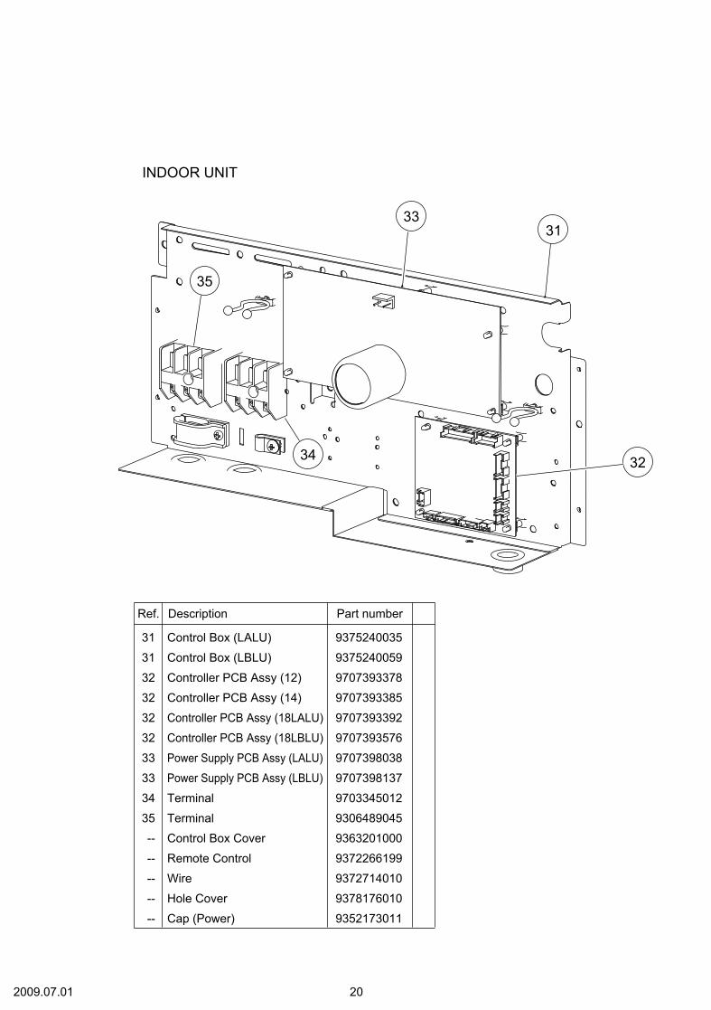
INDOOR UNIT
2009.07.01 20
3331
32
35
34
32 Controller PCB Assy (12)
31 Control Box (LALU)
34 Terminal
35 Terminal
33 Power Supply PCB Assy (LALU)
Ref. Description Part number
9707393378
32 Controller PCB Assy (14) 9707393385
32 Controller PCB Assy (18LALU) 9707393392
32 Controller PCB Assy (18LBLU) 9707393576
9375240035
31 Control Box (LBLU) 9375240059
9703345012
9306489045
9707398038
33 Power Supply PCB Assy (LBLU) 9707398137
-- Wire
-- Hole Cover
-- Remote Control
9372714010
9378176010
-- Cap (Power) 9352173011
9372266199
-- Control Box Cover 9363201000

2008.08.01 21
1
2
9
7
5
6
34
OUTDOOR UNIT
PARTS
8
1 Top Panel Assy
3 Cabinet Assy4 Blow Down Grille5 Cabinet Right Assy6 Fan Ring7 Grip
9 Protective Net8 Emblem
9309230057
93148090402 Cover (Switch) Assy 9309237032
9308884015930923601193088850129308880017
93153190129315210012
Ref. Description Part number

2008.07.31 22
18
19
41
10
20
32
13
35
40
21
17
14
11
34
16
15
OUTDOOR UNIT
37
38
37
39
22
10 4-Way Valve11 Pulse Motor Valve Assy13 Condenser Assy14 Thermistor Spring-A15 Thermistor Spring16 Propeller Fan17 Nut18 Motor Bracket19 Separator Assy20 Base Assy21 3-Way Valve Assy22 2-Way Valve Assy32 Expansion Valve Coil34 Fan Motor35 Compressor Assy
Reactor Assy
39 Solenoid Coil
41
Thermistor Assy37
990004701693116410189311382027
38 Heat Exchanger Thermistor 9900403010
31372826270893000890129309909014930490200393088720129312971015930886908199700920159970093012990005703996021330179313763039
9970033018
9900354015
9900148027
Outdoor Thermistor-- 9900210045
Ref. Description Part number
40 Compressor Thermistor 9900156046

2009.07.01 23
26
4243
30
28
29
27
OUTDOOR UNIT
26 Inverter PCB Assy (AOYA12)
29 Fuse
Terminal4230 Fuse
27 Fuse Holder28 Fuse Holder
Ref. Description Part number
9707427035
26 Inverter PCB Assy (AOYA14) 9707427042
26 Inverter PCB Assy (AOYA18) 9707427011
0600382018
9703874031Inverter Case Assy43 9315690012
0600372163
05014540120501456016
26 Inverter PCB Assy (AOYB12) 9707427134
26 Inverter PCB Assy (AOYB14) 9707427141
26 Inverter PCB Assy (AOYB18) 9707427110

ACCESSORIES
INDOOR UNIT
1For drain piping work. 9303029015Drain pipe
1To connect 12,000 BTU model* 12,000 BTU model only
9370244007Adapter assy12.7 mm-> 9.52 mm
Q'ty
OUTDOOR UNITName and Shape Part numberApplication
2008.07.31 24
Name and Shape Q’ty Application
Coupler heatinsulation(large) 1
For indoor side pipejoint (gas pipe)(P/N 9378173569)
Coupler heatinsulation(small) 1
For indoor side pipejoint (liquid pipe)(P/N 9378173521)
Filter
3
For protecting airconditioner againstdust(P/N 9366833017)
Drain hose insulation
1
Insulates the drainhose and vinyl hoseconnection(P/N 313806217708)
1
For making a wiringhole for connectingoptional units(P/N 9364788005)
Name and Shape Q’ty Application
Installationtemplate
1
For positioning theindoor unit(P/N 9364225005)
Hanger
4
For suspending theindoor unit from ceiling(P/N 9363195002)
Screw(M4 x 10)
8
For installing thehanger(P/N 0700009037)
Special nut A(large flange)
4For suspending theindoor unit from ceiling(P/N 313005446653)
(P/N 313005446759)Special nut B(small flange)
4
Binder (Small)1
For remote controland cord binding(P/N 313361275805)
(Large)4
For fixing the couplerheat insulation(P/N 312300787605)
Remotecontrol 1
For air conditioneroperation(P/N 9372266199)
Remote control cord 1
For connecting theremote control(P/N 9372714010)
Screw(M4 x 16) 2
For installing remotecontrol(P/N 0700181108)
OPTIONAL PARTSThe following options are available.Remote sensor:UTD-RS100 (P/N 9072619004)External control set:UTD-ECS5A (P/N 9077359004)Drain pump unit : UTZ-PX1BBA (P/N 9052976004)Receiver unit : UTY-LRHX1 (P/N 9048213007)
Edge cover

0805G3476