investigation microstructure and mechanical …umpir.ump.edu.my/id/eprint/2897/2/cd5983.pdf ·...
TRANSCRIPT

2
INVESTIGATION MICROSTRUCTURE AND MECHANICAL PROPERTIESOF WHITE CAST IRON USING SAND CASTING
MUHAMMAD SAIFUL AZZAM BIN HAMDAN
Report submitted in partial fulfillment of the requirementsfor the award of the degree of
Bachelor of Mechanical Engineering with Manufacturing Engineering
Faculty of Mechanical EngineeringUNIVERSITI MALAYSIA PAHANG
AUGUST 2011

v
ABSTRACT
This project is to investigate mechanical properties and microstructure of whitecast iron using sand casting. There are three objectives for this project which are firstlyto study the processing method of gray cast iron to produce white cast iron. Secondly, toinvestigate the microstructure and hardness of white cast iron compared to gray castiron and lastly, to study the microstructure and hardness of white cast iron in differentialtype of quenching medium. The first part for this project is foundry laboratory which isinvolving the process of sand casting was performed by using furnace to melt the rawmaterial. Then, the melted raw material produced is then poured into the desired mouldand let it solidify by itself. After the casting process, the material will be through secondpart which involves heat treatment. The material is heated at 1020oC for two hours.Then, the material is quenched into the medium of water and oil before inspectionparameter was performed to investigate the mechanical properties (hardness) andmicrostructure of material before and after heat treatment process. To validate theprediction result, experimental values compared. Result showed that the hardness ofmaterial after heat treatment is higher than hardness before heat treatment. The grainsize formed on material after heat treatment is finer grain size and there are no flakes.Different with material before heat treatment, it shows that there are flakes and the grainsize is thin inside it. The predicted result showed that heat treatment exerted on materialis influencing the change of mechanical properties and microstructure.

vi
ABSTRAK
Projek ini menerangkan kajian sifat-sifat mekanik dan perubahan mikrostrukturbesi tuang putih menggunakan proses tuangan logam. Projek ini mempunyai tigaobjektif pertama, mengkaji kaedah memproses besi tuang kelabu kepada besi tuangputih. Kedua, mengkaji mirostruktur dan kekerasan besi tuang putih berbanding denganbesi tuang kelabu dan ketiga, mengkaji mikrostruktur dan kekerasan besi tuang putihpada medium lindap kejut yang berbeza. Bahagian pertama bagi projek ini melibatkanproses tuangan logam dilakukan dengan menggunakan relau untuk mencairkan bahanmentah. Kemudian, bahan mentah cair yang dihasilkan tadi dituangkan ke dalam acuanyang dikehendaki dan ia dibiarkan sejuk dengan sendirinya. Selepas proses tuanganlogam, bahan tersebut akan melalui bahagian kedua yang melibatkan rawatan haba.Bahan dipanaskan pada suhu 1020oC selama 2 jam. Kemudian, bahan direndamkan kedalam air dan minyak sebelum pemeriksaan parameter dilakukan untuk mengkaji sifat-sifat mekanikal (kekerasan) dan mikrostruktur bahan sebelum dan selepas prosesrawatan haba. Untuk mengesahkan hasil ramalan, keputusan daripada eksperimendibandingkan. Keputusan menunjukkan bahawa kekerasan bahan selepas rawatan habaadalah lebih tinggi daripada kekerasan sebelum rawatan haba. Saiz butiran yangterbentuk pada bahan selepas rawatan haba adalah lebih halus dan tidak terdapatkepingan-kepingan padanya. Berbeza dengan bahan sebelum rawatan haba, iamenunjukkan bahawa terdapat kepingan dan saiz butiran nipis di dalamnya. Hasilramalan menunjukkan bahawa rawatan haba yang dikenakan ke atas bahanmempengaruhi perubahan sifat-sifat mekanikal dan mikrostruktur.

vii
TABLE OF CONTENTS
SUPERVISOR DECLARATION
STUDENT DECLARATION
ACKNOWLEDGEMENT
ABSTRACT
ABSTRAK
TABLE OF CONTENT
LIST OF TABLES
LIST OF FIGURES
CHAPTER 1 INTRODUCTION
1.1 Background
1.2 Problem Statement
1.3 Project Objectives
1.4 Project Scopes
CHAPTER 2 LITERATURE REVIEW
2.1 Introduction
2.2 Metal Casting Process
2.2.1 Pattern2.2.2 CO2 Sand Mould2.2.3 The Formation of Gray Cast Iron
2.3 Cast Iron2.3.1 Gray Cast Iron2.3.2 White Cast Iron2.3.3 Malleable Cast Iron2.3.4 Ductile Cast Iron
2.4 Microstructure Of White Cast Iron
2.5 Mechanical Properties
2.6 Heat Treatment
2.6.1 Quenching2.6.2 Quenching Medium
ii
iii
iv
v
vii
i
x
xi
1
2
2
2
3
3
456
67788
8
11
11
1212

viii
2.6.2.1 Water2.6.2.2 Oil
2.7 Mechanical Properties Testing
2.7.1 Hardness Testing
CHAPTER 3 METHODOLOGY
3.1 Introduction
3.2 Design of Experiment
3.3 Sand Casting Process
3.3.1 Preparation of Pattern3.3.2 CO2 Sand Mould Making3.3.3 Melting Raw Material3.3.4 Pouring Molten Metal Into Mould3.3.5 Felting
3.4 Sample Preparation
3.4.1 Surface Grinding3.4.2 EDM-Wire Cut
3.5 Gray Cast Iron Analysis
3.6 Heat Treatment (Quenching)
3.7 Material Analysis
3.7.1 Metallographic Examination
3.7.1.1 Mounting Process3.7.1.2 Grinding Process3.7.1.3 Polishing Process3.7.1.4 Microstructure View
3.7.2 Hardness Test
3.7.2.1 Rockwell Hardness Test
CHAPTER 4 RESULT AND DISCUSSION
4.1 Introduction
4.2 Result
4.2.1 Microstructure Analysis4.2.2 Relationship Heat Treatment to Material Microstructure4.2.3 Rockwell Hardness Test4.2.4 Relationship Heat Treatment to Material Hardness
1313
13
13
15
15
18
1920212122
22
2323
24
24
25
25
25262728
29
29
30
30
30
30333437

ix
4.2.5 Effect of Quenching Medium to The Microstructure AndHardness of White Cast Iron
CHAPTER 5 CONCLUSION AND RECOMMENDATIONS
5.1 Introduction
5.2 Conclusion
5.3 Recommendations
REFERENCES
APPENDIXES
A Tables of Rockwell hardness scales
B Gant chart for Final Year Project 1
C Gant chart for Final Year Project 2
37
39
39
39
40
41
43
45
46

x
LIST OF TABLES
Table No. Title Pages
2.1
2.2
4.1
4.2
4.3
4.4
Chemical composition of white cast iron
Mechanical properties of white cast iron
Microstructure capture before undergoes heat treatment
process (gray cast iron)
Microstructure capture after undergoes heat treatment
process (white cast iron)
Rockwell hardness test of gray cast iron (before heat
treatment)
Rockwell hardness test of white cast iron (after heat
treatment)
9
11
31
32
34
35

xi
LIST OF FIGURES
Figure No. Title Pages
2.1
2.2
2.3
2.4
3.1
3.2
3.3
3.4
3.5
3.6
3.7
3.8
3.9
3.10
3.11
3.12
3.13
3.14
4.1
Metal casting process
Microstructure of white cast iron containing massive
cementite (white) and pearlite etched with 4% natal, 100x
High magnification view (400x) of the white cast iron
specimen, etched with 4% nital
Hardness testing machine
Flow chart PSM
Experiment setup
Flow chart for sand casting process
Top view of pattern design
A batch muller mixer
Pouring the molten metal from furnace to ladle
Pouring the molten metal from ladle to mould
Hand grinder
EDM-wire cut machine
Heat treatment furnace
Mounting machine
The vertical grinding machine
Polishing machine
Image Analyzer
Graph Rockwell hardness number versus number of test
4
10
10
14
16
17
18
19
20
21
22
23
24
25
26
27
28
28
36

1
CHAPTER 1
INTRODUCTION
1.1 BACKGROUND
Basically there are four different kinds of cast irons whereby can be differentiated
from each other by the distribution of carbon in their microstructure; gray cast iron, white
cast iron, ductile cast iron and malleable cast iron. White cast iron is unique since it is the
only member of the cast iron family in which carbon is present only as carbide. Due to the
absence of graphite, it has a light appearance. The presence of different carbides, depending
on the alloy content, makes white cast irons extremely hard and abrasion resistant but very
brittle. An improved form of white cast iron is the chilled cast iron. The raw material
required to carry out this project is pig iron. Pig iron is a metal material that results when
iron ore, charcoal from coal, and limestone are melted together under intense air pressure.
Pig iron formed when the combined material cools to form a high-carbon. The cooled
material is rarely used by itself, as the large amount of carbon makes the material brittle
and unstable. Usually, this type of iron is further refined through additional melting and
blending processes to create wrought iron, cast iron, or steel. This project will through the
metal casting and heat treatment process to achieve and gain the objective agreed. In order
to obtain the absolute result, there are several method and tests that must be done to
investigate the microstructure and mechanical properties of white cast iron such as using
the microscope and hardness test.
2
1.2 PROBLEM STATEMENT
Since there are limitation of the mechanical properties of gray cast iron such as
hardness, tensile strength and others so, the white cast iron is needed. The mechanical
properties of white cast iron is better than grey cast iron in order to produce something that
need strength and ability to against the large force exerted on it. The white cast irons are
used primarily for applications requiring wear and abrasion resistance such as mill liners
and shot-blasting nozzles. Besides that, other uses include railroad brake shoes, rolling-mill
rolls, clay-mixing and brickmaking equipment, and crushers and pulverizers.
1.3 PROJECT OBJECTIVES
a) To study the processing method of the gray cast iron to produce white cast iron.
b) To investigate the microstructure and the hardness of white cast iron compared to
gray cast iron.
c) To study the microstructure and hardness of white cast iron in differential type of
quenching medium (oil and water).
1.4 PROJECT SCOPES
The scope of study for this project includes the using of CO2 sand as a mould in
carry out the sand casting process. Other than that, the raw material used in sand casting
process is pig iron which is as a basic thing in producing gray cast iron. In order to generate
the white cast iron, the heat treatment (quenching) need to be held by reheating the gray
cast iron then followed by rapid cooling. Then, an inspection parameter is performed to
investigate the microstructure and mechanical properties (hardness) before and after heat
treatment and all of them will be studied by suitable test and method.

3
CHAPTER 2
LITERATURE REVIEW
2.1 INTRODUCTION
In this chapter, it basically describes more about the investigation of white cast iron
microstructure and mechanical properties using green sand molding process done by other
scientists and engineers. Therefore, in this part will discuss on white cast iron and its
microstructure. Then, it is followed by mechanical properties and sand casting process.
2.2 METAL CASTING PROCESS
Casting is a 6000 year young process which is mentioned in several Sanskrit works
such as Shilpashastra derived from Sthapatyaveda containing the principles of realizing all
kinds of man-made structures (Ravi, 2005). Earliest castings include the 11 cm high bronze
dancing girl found at Mohenjo-do in between the range dated 3000-3500 BC (Ravi, 2005).
Besides that, there was remain of Harappan civilization contain kilns for smelting copper
ingots, casting tools, stone moulds, cast ornaments, figurines and others items of copper,
gold, silver and lead (Ravi, 2005).
Metal casting enables the production of simple and complex parts that meet a wide
variety of needs and all manufactured goods contain one or more cast components. The
basic metal casting process involved pouring or injecting molten metal into a mold or die
containing a cavity of the desired shape. Most commonly used method for small and

4
medium-sized castings is green sand casting and it is a traditional method of casting metals
and has been used for millennia. Basically, sand casting consists of (a) placing a pattern
(having the shape of desired casting) in sand to make an imprint, (b) incorporating a gating
system, removing the pattern and filling the mold cavity with molten metal, (d) allowing
the metal to cool until it solidifies, (e) breaking away the sand mold, and (f) removing the
casting. Other methods include die casting, shell molding, investment casting, lost foam
casting, and squeeze casting. So, in this project, the green sand or CO2 will be used as a
mould. This method is the most common metal casting technique, using silica sand (SiO2)
as a medium for the mould. The sand is coated with a mixture of clay and water and
pressed manually or mechanically around the pattern to be cast. The advantages of this
project are most ferrous and nonferrous metals can be used and low pattern and material
costs. Green sand molding is frequently the most economical method of producing castings.
Figure 2.1: Metal Casting Process
2.2.1 Pattern
Patterns are the foundry man’s mould forming tool. Pattern is used to form mould
cavity in which molten metal is poured. A pattern is a replica of the part or component to be
5
made by casting process. Pattern replicates the mould cavity and allows the molten metal to
solidify inside the mould.
Wood is the most common used of pattern material because it is easy availability,
low weight and low cost (Parashar and Mittal, 2006). It is easily to shape, join, work and
relatively cheap compare to others pattern material like metal. 90% of the castings are
produced by using wood pattern (Parashar and Mittal, 2006). The limitation for the wood
pattern is lower life and economical for small quantity production.
Shrinkage allowance is the amount that a pattern is made over size to compensate
for the contraction of the casting metal (Parashar and Mittal, 2006). It is the contraction
during cooling to room temperature. All metal shrink when cooling except perhaps bismuth
because of inter-atomic vibrations which are amplified by an increase in temperature.
2.2.2 CO2 Sand Mould
The CO2 sand process used rammed moist sand that is bound together with sodium
silicate which is hardened on the pattern by blowing CO2 gas through the mould (Lindberg,
1990). This method gives a good surface finish and high accuracy which reduce the
machine allowance and versatile easier for small, medium and large foundries for light and
heavy casting for ferrous and non-ferrous foundries alike (Jain, 1995).
Basically, this procedure is more accurate mould than either green sand and it
avoids baking (Lindberg, 1990). It is better withstanding handling and metal head pressure
such that a dry compressive strength of over 1.4 MPa is arrived. The carbon dioxide is
expected to form a weak acid which hydrolyses the sodium silicate resulting in amorphous
silica which forms the bond. The introduction of CO2 gas starts the reaction by forming
hydrated sodium carbonate (Na2CO3 + H2O). This gelling reaction increases the viscosity

6
of the binder till it becomes solid. The compressive strength of the bond increases with
standing time due to dehydration. The gassing of carbon dioxide pressure should be
maintained around 0.14 to 0.28 MPa depending largely on the section to be gassed (Rao,
1998).
2.2.3 The Formation of Gray Cast Iron
Gray cast iron is formed when the carbon in the alloy exceeds the amount that can
dissolve in the austenite and precipitates as graphite flakes. When a piece of solidified gray
iron is fractured, the fracture surface appears gray because of the exposed graphite. Gray
iron is very easy and cost effective to make, making it a highly popular iron alloy. Its
properties make it highly suitable for a wide range of uses, and examples of this iron alloy
can be seen in many locations around the world, including museums which maintain
products of historic interest. This iron alloy has properties which can vary slightly,
depending on how quickly it cools and the concentration of various elements in the alloy.
The key feature of grey iron is that it includes flakes of graphite which develop during the
cooling process.
2.3 CAST IRON
The term cast iron refers to a family of ferrous alloys composed of iron, carbon
(range from 2.11% to about 4.5%), and silicon (up to about 3.5%). Cast irons are usually
classified according to their solidification morphology from the eutectic temperature. Cast
iron are also classified by their structure; ferritic, pearlitic, quenched and tempered or
austempered. Cast irons have relatively low melting temperatures and liquid-phase
viscosities, do not form undesirable surface temperatures and undergo moderate shrinkage
during solidification and cooling. The cast irons must balance good formability of complex
shapes against inferior mechanical properties compared white those of wrought alloys. A
cast iron is formed into a final shape by pouring molten metal into a mold. The shape of the
mild is retained by the solidified metal.

7
2.3.1 Gray cast iron
In this structure, graphite exists largely in the form of flakes. It is called cast iron
because when it is broken, the fracture path is along the graphite flakes and has, therefore a
gray, sooty appearance. These flakes act as stress raisers. As a result, gray cast iron has
negligible ductility and it is weak in tension, although strong in compression, as are other
brittle materials
.On the other hand, the presence of graphite flakes gives this material the capacity to
dampen vibrations caused by internal friction and consequently the ability to dissipate
energy. This capacity makes gray cast iron a suitable and commonly used material for
constructing machine-tool bases and structures.
2.3.2 White cast iron
White cast iron is formed when much of the carbon in a molten cast iron forms iron
carbide instead of graphite upon solidification. The microstructure of as-cast unalloyed
white cast iron contains large amounts of iron carbides in a pearlitic matrix. To retain the
carbon in the form iron carbide in white cast irons, their carbon and silicon contents must
kept relatively low (that is, 2.5 – 3.0 percent C and 0.5 – 1.5 percent Si) and the
solidification rate must be high. White cast irons are most often used for their excellent
resistance to wear and abrasion. The large amount of iron carbides in their structure is
mainly responsible for their wear resistance. White cast iron also serves as the raw material
for malleable cast irons.
The white cast iron structure is very hard , wear resistant, wear resistant and brittle
because of the presence of large amounts of iron carbide(instead graphite). White cast iron
is obtained cooling gray cast iron rapidly or by adjusting the composition by keeping the
carbon and silicon content low. This type of cast iron is also called white iron because of
the white crystalline appearance of the fracture surface.

8
2.3.3 Malleable Cast Iron
Malleable cast iron is obtained by annealing white cast iron in an atmosphere of
carbon monoxide and carbon dioxide at between 800 oC and 900 oC for up to several hours,
depending on the size of the part. During this process the cementite decompose into iron
and graphite. The graphite exists as clusters or rosettes.in a ferrite or pearlite matrix;
consequently, malleable cast iron has a structure similar to the nodular iron. This structure
promotes ductility, strength and shock resistance.
2.3.4 Ductile Cast Iron
This structure is developed from the melt. The carbon forms into spheres when
cerium, magnesium, sodium, or other elements are added to a melt of iron with a very low
sulfur content that will inhibit carbon from forming. The control of the heat-treating process
can yield pearlitic, ferritic, martensitic matrices into which the carbon spheres are
embedded.
2.4 MICROSTRUCTURE OF WHITE CAST IRON
A very small amount of the carbon is dissolved in the pure iron matrix. This
component of the microstructure is known as Ferrite. Further amounts of carbon can either
form Iron Carbide, [Fe3C], which is hard and brittle, or Graphite, which is almost pure
carbon and is soft and has little strength. The form the carbon takes is determined by the
rate of cooling during solidification, by the influence of other alloying elements and by
subsequentthermaltreatment.
In white cast iron, there is little or no graphite in the structure and this is causing the
material is very hard and brittle; in contrast to the grey fracture where graphite is present.
Where larger proportions of graphite are formed, the shape and size of the graphite has a
significant effect on the properties of the cast iron. Other elements which are present in the

9
alloy affect the form of the graphite and the structure and properties of the material matrix.
The chemical composition of white cast iron generally conforms to the ranges given in the
Table 2.1.
Table 2.1: Chemical composition of white cast iron (Source: Janina M. Radzikowska,
2001)
Element Composition (%)
Carbon 1.8 - 3.6
Silicon 0.5 - 1.9
Manganese 0.25 - 0.80
Sulfur 0.06 - 0.20
Phosphorus 0.06 - 0.20

10
Figure 2.2: Microstructure of white cast iron containing massive cementite (white) and
pearlite etched with 4% nital, 100x.
(Source: http://www.metallography.com)
Figure 2.3: High magnification view (400x) of the white cast iron specimen, etched with
4% natal.
(Source: http://www.metallography.com)
11
2.5 MECHANICAL PROPERTIES
The mechanical properties of a material describe how it will react to physical forces.
The mechanical properties of a material are those properties that involve a reaction to an
applied load. The mechanical properties of metals determine the range of usefulness of a
material and establish the service life that can be expected. Mechanical properties are also
used to help classify and identify material. The most common properties considered are
strength, ductility, hardness, impact resistance, and fracture toughness. Mechanical
properties occur as a result of the physical properties inherent to each material, and are
determined through a series of standardized mechanical tests. These are the several
mechanical properties for white cast iron.
Table 2.2: Mechanical properties of white cast iron (Source: http://www.matweb.com)
Mechanical Properties Metric
Hardness, Rockwell 47.1 - 54.4 HRC
Tensile Strength Ultimate 345 – 689 MPa
Modulus of Elasticity 165 – 179 GPa
Izod Impact Unnotched 40.7 – 244 J
2.6 HEAT TREATMENT
Heat treatment involves the improvement of properties of metals and alloys by
changing their microstructure. Heat Treating is controlled heating and cooling of a solid
metal or alloy by methods designed to obtain specific properties by changing the
microstructure. Heat Treating takes place below the melting point of the metal and changes
in microstructure take place within the solid metal. Changes in microstructure are due to the
movement of atoms within crystal lattices in response to heating or cooling over a period of

12
time. The ability to tailor properties by heat treating has contributed greatly to the
usefulness of metals and their alloys in an assortment of applications such as sheet metal
for cars and aircraft.
Heat treating processes include annealing, normalizing, tempering, stress relieving,
solution treating, age hardening, and bright hardening. Quenching, or cooling from a higher
temperature, is an integral part of many heat treating processes when hardening is involved.
2.6.1 Quenching
Quenching is an accelerated method of bringing a metal back to room temperature,
preventing the lower temperatures through which the material is cooled from having a
chance to cause significant alterations in the microstructure through diffusion. Quenching
can be performed with forced air convection, oil, fresh water, salt water and special purpose
polymers.
The slower the quench rate, the longer thermodynamic forces have a chance to alter
the microstructure, which is in some cases desirable, hence the use of different media.
When quenching in a liquid medium, it is important to stir the liquid around the piece to
clear away steam from the surface; steam pockets locally defeat the quench by air cooling
until they are cleared away.
2.6.2 Quenching Medium
Quenching media is very important to hardening because it is a very effective of hardness
of the material.

13
2.6.2.1 Water
Water is fairly good quenching medium.it is cheap,readily available, easily stored
nontoxic nonflammable smokeless and easy to filer and pump but with water quench the
formation of bubbles may cause soft spots in the metal.Agitation is recommended with use
of water quench.Still other problems with waterquench inclued its oxidizing nature,its
corrosivity and the tendency to excessive distortion and cracking although this bad
properties for plain carbon steels.
2.6.2.2 Oil
When slower cooling rate is desired oil quenches can be employed.The slower
cooling throug the ms to mf temperature range leads to a milder temperature gradient and a
reduced likelyhood of cracking.Problems associated with quenchants include water
contamination,smoke and fire hazards.in addition quench oils tend to be somewhat
expensive.
2.7 MECHANICAL PROPERTIES TESTING
The mechanical properties of a material are those properties that involve a reaction
to an applied load. The mechanical properties of metals determine the range of usefulness
of a material and establish the service life that can be expected. Mechanical properties are
also used to help classify and identify material. The most common properties considered
are strength, ductility, hardness, impact resistance, and fracture toughness.
2.7.1 Hardness Testing
Hardness is the property of a material that enables it to resist plastic deformation,
usually by penetration. However, the term hardness may also refer to resistance to bending,
scratching, abrasion or cutting. Hardness is not an intrinsic material property dictated by

14
precise definitions in terms of fundamental units of mass, length and time. A hardness
property value is the result of a defined measurement procedure.
The usual method to achieve a hardness value is to measure the depth or area of an
indentation left by an indenter of a specific shape, with a specific force applied for a
specific time. There are three principal standard test methods for expressing the relationship
between hardness and the size of the impression, these being Brinell, Vickers, and
Rockwell. For practical and calibration reasons, each of these methods is divided into a
range of scales, defined by a combination of applied load and indenter geometry.
Figure 2.4: Hardness Testing Machine
(Source: www.shuennyueh.com)

15
CHAPTER 3
METHODOLOGY
3.1 INTRODUCTION
Methodology can properly refer to the theoretical analysis of the methods
appropriate to conduct a project or study which is of most importance to ensure a smooth
development of the study.
This chapter provides a discussion of the methodology used in conducting this
project from starting until it is completed. The microstructure and hardness of gray cast iron
and white cast iron will be investigated.
3.2 DESIGN OF EXPERIMENT
This foundry laboratory was prepared to investigate the effect mechanical properties
and change in microstructure of white cast iron using sand casting and heat treatment
process. In this process, it consisted of process pattern making, mould making, melting
procedure, pouring the molten metal into the mould, felting and then followed by heat
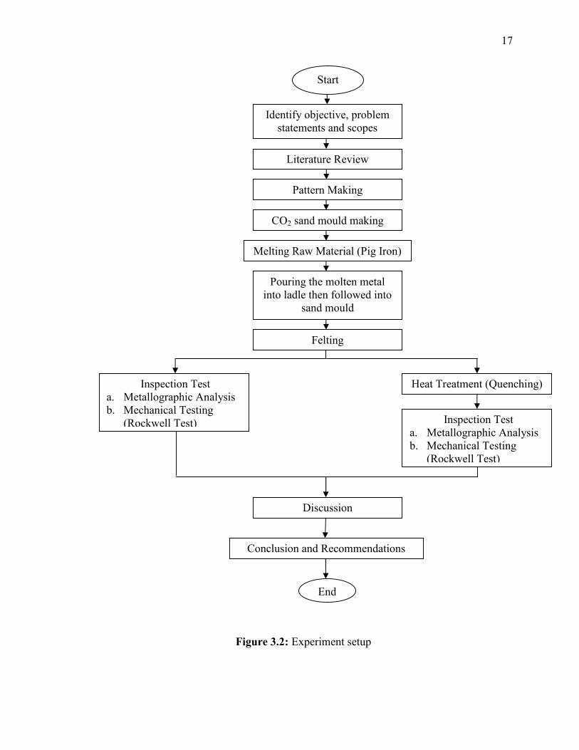
treatment process (in order to produce white cast iron). Before run the experiment, a
methodology flow chart of experiment flow was shown in Figure 3.2.

16
Figure 3.1: Flow chart PSM
Literature Review
Prepare experiment setup up
Problem Identification
Discuss expected result
Report writing and slidepreparation
Start
Run experiment
Analysis data and result
Discussion
Complete report and presentation slide
Present toSupervisor
Selection ofparameter
Submit report
No
Yes
Yes
Modification
No
17
Figure 3.2: Experiment setup
Start
Identify objective, problemstatements and scopes
Literature Review
Inspection Testa. Metallographic Analysisb. Mechanical Testing
(Rockwell Test)
CO2 sand mould making
Pouring the molten metalinto ladle then followed into
sand mould
Felting
Pattern Making
Heat Treatment (Quenching)
Inspection Testa. Metallographic Analysisb. Mechanical Testing
(Rockwell Test)
Melting Raw Material (Pig Iron)
Discussion
Conclusion and Recommendations
End

18
3.3 SAND CASTING PROCESS
Gray cast iron is produced by metal casting. The raw material, pig iron has been
used as a fuel and it melted in the furnace at temperatures range 1200oC to 1400oC. The
molten metal is then poured into molds that have been made to get the desired form and
substance. The material produced is gray cast iron after it has cooled for a while in the
mold. Figure 3.3 shows the flow chart of sand casting process.
Figure 3.3: Flow chart for sand casting process.
Pattern making
CO2 sand mould making
\
Melting raw material (pig iron)
\Pouring molten metal into ladle
Pouring molten metal into CO2 sand mould
\
Felting
\
Define part geometry & required properties.
19
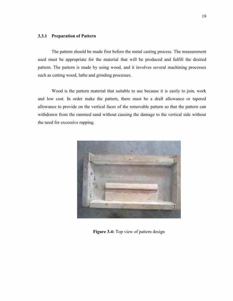
3.3.1 Preparation of Pattern
The pattern should be made first before the metal casting process. The measurement
used must be appropriate for the material that will be produced and fulfill the desired
pattern. The pattern is made by using wood, and it involves several machining processes
such as cutting wood, lathe and grinding processes.
Wood is the pattern material that suitable to use because it is easily to join, work
and low cost. In order make the pattern, there must be a draft allowance or tapered
allowance to provide on the vertical faces of the removable pattern so that the pattern can
withdrawn from the rammed sand without causing the damage to the vertical side without
the need for excessive rapping.
Figure 3.4: Top view of pattern design

20
3.3.2 CO2 Sand Mould Making
Basically, CO2 sand mould had better withstanding handling and high metal head
pressure. The bonding strength between obtained by the hardening action is sufficient to
eliminate baking and drying of the mould. The metal can be poured immediately. For
common used of sodium silicate used for CO2 gas should have a mass ratio varying 2.1 to
2.3 (Jain, 1995).
Muller and mixer are required to ensure proper mixing and dispersion of sand bond
with sodium silica. Then, let the Muller machine running for a period of time so that
sodium silicate and silica. The sand is continuing rammed so that it is pack and possesses
certain strength. After the silica sand is ready, it transferred into drag as shown in Figure
3.5. Before placed the silica sand same height as the drag, the pattern was applied parting
powder to help easier remove sand mould. Make some holes on the sand mould before the
CO2 gas was applied on it.
Figure 3.5: A batch muller mixer

21
3.3.3 Melting Raw Material
The raw material used is pig iron which is put in the furnace and let it melt for a
sudden time until the raw material of pig iron from solid form become molten metal.
Usually the slag was discovering in the molten metal due to the stirring effect in the
furnace. So, a slag catcher is used to filter the slag from the furnace and remove the slag
from time to time in order to ensure level of purify molten metal was produced. The
sufficient time must be provided before proceed to transport to the ladle for pouring
process.
3.3.4 Pouring Molten Metal Into Mould
During the process of pouring, the ladle was use to transfer the molten metal from
the furnace to the mould. For the fast pouring will minimize the temperature loss during
mould cavity filling and this can reducing the rate of oxidation and metallurgical fade. For
constant flow rate of molten metal can help to reduce the defects during the process of
solidification.
Figure 3.6: Pouring the molten metal from furnace to ladle

22
Figure 3.7: Pouring the molten metal from ladle to mould
3.3.5 Felting
The complete process of the cleaning of casting is called felting which is involves
the removal of the gate system. This process is separating out the casting product and
cleaning the casting surface. First step hammer is used to knock out the casting from the
sand mould. Follow by the abrasive cut off to remove the gating system. The last step
before go for the inspection parameter is cleaning the sand particle sticking to the casting
surface by sand blasting. The casting is kept in the closed box and a jet of compressed air
with a blast if sand grains were directed against the casting surface.
3.4 SAMPLE PREPARATION
The specimen preparation process is important to be done for the next process.
Small specimens should be obtained to facilitate the process of heat treatment and analysis
that will be done next. Besides that, the specimen also necessary to be cleaned on it in order
to facilitate the microstructure of the specimen can be seen clearly.

23
For this part, 3 samples of specimens are needed. The first one is for the gray cast
iron analysis and others will be used for the heat treatment process in order to obtain the
white cast iron and they also will be analyzed
3.4.1 Surface Grinding
The surface of gray cast iron is then cleaned using a hand grinder. The goal is to
remove impurities resulting from the pouring of molten metal during the process of metal
casting.
Figure 3.8: Hand Grinder
3.4.2 EDM-Wire Cut
EDM wire cut is a cutter that appropriate to cut the gray cast iron. Gray cast iron is
cut into three small specimens to facilitate the process of heat treatment and analysis will be
done in the next. The process of wire cut machine is the machine using the process of
erosion resulting from the potential difference through a wire. The electrode is a wire coil
that continuously rotates and turns over the engine going.

24
Figure 3.9: EDM-Wire Cut Machine
3.5 GRAY CAST IRON ANALYSIS
The gray cast iron produced by metal casting is investigated in term of its
microstructure and mechanical properties. After the preparation process to get the shiny
surface of experimental material is done, the experimental material can already test on
microscope to view the microstructure. The microstructure’s image will be adjusted by the
viewer until the image of the structure appearance on screen of computer by using its own
software. From that, the image can be seeing clearly. Then, the hardness of gray cast iron is
obtained through the related test.
3.6 HEAT TREATMENT (QUENCHING)
This process is important in order to produce the white cast iron. The specimens are
heated in heater furnace at 1020°C or 1293 K for 2 hours. (Zhongli Liu, Yanxiang Li,
Xiang Chen and Kaihua Hu, 2008). Then the specimens are cooled in the two different
medium, water and oil. The first specimen is soaked in the water for 2 seconds and the
second specimen is soaked in the oil for 30 seconds.