investigation of complex mass and heat transfer … · 2019. 8. 2. · heat and mass transfer...
TRANSCRIPT
INVESTIGATION OF COMPLEX MASS AND HEAT TRANSFER TRANSITIONAL PROCESSES OF DISPERSED WATER DROPLETS IN WET GAS FLOW IN THE
FRAMEWORK OF HEAT UTILIZATION TECHNOLOGIES FOR BIOFUEL COMBUSTION AND FLUE GAS REMOVAL
G. Miliauskas 1, M. Maziukienė1, H. Jouhara2 and R. Poškas1,3
1. Department of Thermal and Nuclear Energy, Faculty of Mechanical Engineering and Design, Kaunas
University of Technology, Kaunas, Lithuania; email: [email protected]
2. College of Engineering, Design and Physical Sciences, Institute of Energy Futures, Brunel University
London, UK; email: [email protected]
3. Nuclear Engineering Laboratory, Lithuanian Energy Institute, Kaunas, Lithuania; email:
ABSTRACT In this paper, complex processes of water droplet heat and mass transfer are analyzed in a cycle of condensing,
transitional evaporation and equilibrium evaporation regimes during phase change which occurs on a droplet’s
surface. The dynamics of a heated droplet’s surface temperature is directly related to the change in the regimes.
The definition of the dynamics is based on a numerical iterative scheme which depends on the balance of a
droplet surface’s heat flux. In this scheme, the energy of phase change and external heat transfer are combined
as well as the internal heat transfer occurring in droplets. The numerical investigation results of the water
droplets’ phase change were used as a basis while defining the inputs provided by the droplet slipping and the
radiation absorbed in the flue gas within the interactions between the processes of complex transitional
transfers. For this investigation, the conditions have been set to be typical for heat utilization technologies and
biofuel furnaces used in flue gas removal.
Keywords: water droplets, convective radiative combine heating, condensation and transitional evaporation
regimes of phase change, numerical modelling
Abbreviations: a is thermal diffusivity, m2/s; TB is Spalding transfer parameter; lC is droplet drag coefficient; D is mass
diffusivity, m2/s; Fo is Fourier number; �̇� is vapor mass flow rate, kg/s; Iω is spectral intensity of radiation, W/(m steer); kc is
effective conductivity parameter; k is spectral index of absorption; L is latent heat of evaporation, J/kg; m is vapor mass flux,
kg/(m2s); M is mass, kg; n is spectral index of refraction; n is complex’s spectral index of refraction; Nu is Nusselt number; p
is pressure, Pa; P is symbol of free parameter in heat-mass transfer; Re is Reynolds number; Pr is Prandtl number; q is heat flux,
W/m2; r is radial coordinate, m; R is radius of a droplet, m; Rμ is universal gas constant J/(kmol K); T is temperature, K; is
molecular mass, kg/kmol; λ is thermal conductivity, W/(m K); is density, kg/m3; is time, s; γ is dynamics viscosity, Pa s; w is
velocity, m/s; is angle between the opposite direction of the normal to the surface and the incident beam, rad; is azimuthal
angle, rad; is spectral coefficient of absorption, m-1;. Subscripts: c is convective; f is phase change; g is gas; i is time index in
a digital scheme; it is number of iteration; IT is number of final iteration of iterative cycle; I is index of control time; j is index of
radial coordinate; J is index of droplet surface; co is condensation; l is liquid; m is mass average; tf is transit phase transformation
regime; r is radiation; R is droplet surface; sr is radiation source; v is vapor; vg is vapor-gas mixture; is spectral; is total; 0 is
initial state; is far from a droplet; + is external side of a droplet surface; - is internal side of a droplet surface.
1 INTRODUCTION
Heat and mass transfer processes in liquid droplets are the basis for a number of energy and industrial
technologies. Water dispersion is used for air conditioning, cooling of high temperature gases, processing of
various surfaces and their protection against intensive thermal effects, the increase of gas turbine efficiency,
and in plasma and laser technologies [1-3], etc. Understanding the thermal hydrodynamical processes of water
droplets and their control is essential in order to optimize existing liquid dispersion technologies and to develop
modern, more efficient ones. The issue here is that complex transfer processes in two-phase droplets and gas

flows happen under conditions of intensive interaction. The level of the interaction intensity is determined by
a number of important factors, for example, the influence of the Stefan’s hydrodynamic flow on the convective
heating and evaporation of droplets, the influence of water droplet slipping in the flow on the external heat
transfer and on the forced liquid circulation within the droplets, and the spectral nature of radiation. The optical
spectral effects of light on the surface of droplets define the intensity of the radiation flow absorption in a
semi-transparent liquid. Spectral radiation models [4-9], etc. allow the evaluation of the radiation input in the
energy state of semi-transparent droplets. A proper knowledge of water spectral characteristics leads to a
successful application of these models when defining radiation absorption in water droplets [10, 11]. In heat
transfer and phase change thermal technologies, the variety of process conditions requires a systematic view
in order to define the regularities of process interaction. For this purpose, the heat and mass transfer analysis
of dispersed liquid droplets is a convenient tool in the cycle of consistently changing regimes of phase
transitions. In the general case, the phase change cycle of water droplets dispersed in a wet gas flow will
consist of condensation, transitional evaporation, and equilibrium evaporation regimes. Steam condensation
occurs only when the temperature of the dispersed water is below the dew point. In the transitional evaporation
regime, the droplets are heated to a thermal state that ensures equilibrium evaporation. When such a state is
reached, all heat is then used for water evaporation. The equilibrium evaporation regime of a droplet plays an
important role in technologies based on liquid evaporation, and thus has been thoroughly investigated [12].
The transitional evaporation regime of a droplet has been widely investigated in fuel dispersion technologies
[13]. This study has numerically modeled the transitional phase change of water droplets in a wet gas flow in
the case of complex heating by radiation and convection. The determination of droplet heat transfer boundary
conditions helps to retain the aspects of water dispersion in a biofuel furnace and of the utilization of waste
heat from the flue gas in a condensing shell and tube heat exchanger.
2 METHODOLOGY
Water dispersion can be used to regulate the biofuel combustion process in a furnace, to clean solid
particles from the flue gas as well as to cool and wet it so that the process in a condensing shell and tube heat
exchanger can be effective. In contact type condensing shell and tube heat exchangers, heat is recovered from
the flue gas by condensing water vapor directly onto the dispersed water droplets. For such a technology, it is
usually necessary to control the droplet heating to the dew point temperature and to use a transitional heat
exchanger, the operation of which is usually burdened by condensate polluted with biofuel ash particles. In
such types of condensing shell and tube heat exchangers, the vapor is condensed while the biofuel flue gas is
flowing through the pipes, and thus the fluid flowing at the outside of the pipes receives heat through the wall.
This technology requires optimal vapor condensation. Vapor condensation is a very complex process because
of thermo-hydro-dynamical interaction processes between the polluted flue gas and the condensate’s film. In
order to improve those processes, water is dispersed additionally over the stack of the pipes. In these cases,
consideration should be given to the heating of the dispersed water droplets and transitional phase change
processes taking place at their surface. A complex analysis of droplet external and internal heat transfer and
of phase change processes at the droplets’ surfaces is necessary for the determination of the interaction
between the dispersed water and the biofuel flue gas energy. R and R radii relatively determine the external
and internal surface of spherical droplets. In the case of complex heating, the total heat flux is determined by
radiation and convective components,
cr qqq and
cr qqq , respectively. In condensation co
to0
, transitional evaporation eco
to and equilibrium evaporation fe
to the relation of the heat fluxes
at the surface of a droplet is:
.when,qqq
,when,qqq
,when,qqq
fef
ecof
cof
to
to
to0
(1)
The magnitude of the total heat flux at the surface of the droplets is determined by the intensity of the
complex external heating. The magnitude of the heat flux determines the energy intensity of the phase change
at the droplet surface. The total heat flux at the droplet surface internal side determines the heating intensity

in the water droplets. In the condensation regime, the whole of the heat flux passed onto the droplet surface
heats the water, while in the transitional evaporation regime it is only the part of the heat flux that is excluded
from the evaporation process. In the equilibrium evaporation regime, the water is evaporated by the heat from
the external heat transfer; the change in the enthalpy of cooling droplets may also take place in the process.
Spectral light absorption indicators for water are finite [10]; therefore, it is assumed that water droplets do not
absorb radiation through their surface and rr qq . The external convective heat transfer flux of a droplet is
described according to the model [14], where additionally the universal Spalding heat transfer TB equation is
adopted to phase change regimes according to the methodology in [15]:
c
cRgvgp
TRg
T
vg
T
Tvg
cq
q
L
TTcBTT
BRB
B
Rq 1,
1
PrRe552.0
2
1ln ,
7.0
3/12/1. (2)
In the case of the assumption of the diffusive layer surrounding an evaporating droplet being proportional
to its radius R , to describe the heat flux of phase change, the analytical model [16] for vapour flux is
applied:
.,
.
..,
,
ln, vRv
Rv
v
vg
vvRv
Rvg
vvg
vvf pppp
ppppp
RRT
DmLmq
. (3)
The convective component of the total heat flux in a droplet is defined according to the modified Fourier’s
law:
Rreflc gradTq , , (4)
where the effective thermal conduction coefficient clefl k , s used to take into account the influence of
water circulation on heat transfer within the droplet according to the methodology in [14]. In equation (4) the
temperature gradient is defined by conduction and radiation in a semi-transparent spherical droplet for the case
described by the transcendental system of differential and integral equations:
rlpl q
r
T
rr
Tc
2
1, (5)
iknnkIIns
IdddIqr
,4,,ΘΘcosΘsin 02
0 0
2
0
. (6)
The equation system (1-6) can be solved only using an iterative method, so that unambiguous conditions
for the equations (5, 6) can be formulated with regard to the yet unknown functions of the droplet surface
temperature and spectral radiation intensity at the internal surface of the droplet RI :
,,;,;0;0,0,0,
RRlll IRrITRrTTTTR .0/,0 rrT (7)
A combined analytical-numerical method is applied to solve the system (5-7). At first, the transfer cases
(5) and (7) as well as (6) and (7) are analyzed analytically as independent cases. In the first case, the function
of the local radiation flux ,rqr is assumed to be defined, and in the second case, the function describing the
transient temperature field in a droplet ,rT is assumed to be defined. Using the auxiliary function
RTrTrr ,, , equations (5) and (7) are transformed into the Dirichlet heat transfer case with the
defined source function [7] and the temperature field gradient in the expression (4) is described by an infinite
line of integral equations:
.**
R
r
ll,pn o
R
Rr
dR
naexpdr
R
rncos
R
rn
R
rnsinq
cd
dT
n
Rn
Rr
T
2
012
12. (8)

In the case of the defined radial function rT describing the temperature field in a droplet, the function of the
local radiation flux rqr in equation (8) is calculated using the methodology of reference [6] that takes into
account spectral light effects at both sides of the droplet surface, droplet radiation, and external source
radiation, where the external source is assumed to be a black body with a biofuel flue gas temperature.
The dynamics of the droplet movement in the gas flow and the change in the droplets’ mass and volume
are defined by the following differential equations:
vv
m,ll
lg
lg
l
gll mRmd
Rd
d
dM,
ww
ww
R
C
d
dw 2
3
14
3
4
8
3 . (9)
In respect of the time function RT of the droplet surface temperature, the system of the algebraical and
integral equations (1-4, 7-9) is solved numerically according to the iterative scheme using the fastest
descending method. In order to form the numerical scheme, the non-dimensional coordinates for radius
Rrr / and time co / are introduced (if there is no condensation regime, then tf / ), that ensures
the droplet radius equals 1 ( 1, Rr ), and the duration of the first phase change regime is also 1 ( 1 co
). Then variational steps of the radial and time coordinates are defined as:
,1
1,
1
1
Jr
I ,1
21
I
iii tt .1
21
J
jjj rr (10)
For every time step starting with the second one coii 1 , the descent fastest methods in iterative
it ≡ 1 to IT cycle proceeds to define the instantaneous temperature ITiRiR TT ,,, of the droplet surface. The
droplet surface temperature ITitiRT ,, attributed to the final iteration IT must ensure that the calculated heat
fluxes would fulfill the condition of the expression (1) with a maximum error of five hundredths of a percent:
.05.01001 00
00
,,,,
,,
ITifITic
ITic
q (11)
The droplet heat and mass transfer parameters ,,itiR , ,,
itcq
itcq , and itjiT ,, that are necessary for an it
iteration, however, are not yet defined; they are used from 1it iteration calculated parameters 1,, itiiti PP .
Later the itiP , parameters are revised. The mesh 41,21 JI is used in the numerical modeling; the radiation
spectrum is gradually divided into 1001M parts according to the wave number 310 to
61025.1 . In
equation (8) the number N of the line terms is defined in an infinite sum (
1n
.) i. e., it is assumed that ∞ ≡ N
when N=121. For the defined surface temperature ITiRT ,, , all the necessary instantaneous iP parameters of the
droplet heat and mass transfer are calculated.
3 RESULTS
The biofuel flue gas is defined by the velocity gw , the temperature gT and humidity of ppp vv / , where
MPa.1.0p The dispersion of the water of temperature lT is defined by the dispersion of droplets of diameter
R2 and initial velocity lw . The relative water flow rate is assumed to be 0/ gl GG and therefore the influence
of water droplets on air parameters is not taken into account. The droplet heating process is defined by the
Reynolds number vgglg wwR /2Re . The existence of the radiation source is defined by parameter
gsrsr TTT / : 0srT in the case of convective heating, and 1srT in the case of complex heating.

305
310
315
320
325
330
335
340
345
350
355
360
365
0 0.5 1 1.5 2 2.5 3
TR
, K
Fo
1 2
3 4
5 6
a) 305
310
315
320
325
330
335
340
345
350
355
360
365
0 0.5 1 1.5 2 2.5 3
Tm
, K
Fo
1 2
3 4
5 6
b)
Fig. 1. The influence of water droplet dispersity and heating process on the variation of their surface
temperature (a) and average mass temperature (b). :m,1060 R (1, 2) 50, (3, 4) 100, (5, 6) 1500; :srT (1, 3,
5) 0, (2, 4, 6) 1; :Re0 (1, 2) 49.4, (3, 4) 246.98, (5, 6) 0; :K,0,lT (1-4) 306, (5, 6) 358; m/s,0,lw : (1-4) 65,
(5, 6) 0; m/s,gw : (1-4) 15, (5, 6) 0; K1133gT ; vp : (1-6) 0.2, (7, 8) 0; :/ 200 Ra (1, 2) 53.572, (3, 4)
2.14288, (5, 6) 0.059524.
The results have been analyzed in the time scale of the Fourier number 20/Fo Ra where the individual
multiplier 20/K278 RTa l ensures a more convenient graphical FoP analysis of time functions P
for droplets of different sizes [15]. The time function of the droplet surface temperature RT and the time
function of the average mass temperature mT are important when describing the variation in thermal
condition of the heated droplet. These temperatures are sensitive to the temperature of the dispersed water and
the droplet heating process (Fig. 1). Figure 1 presents the change in the thermal state of water droplets for
different droplet heating processes: curves 1 and 3 represent convective heating, curve 5 conductive heating,
curves 2 and 4 complex heating convection plus radiation, and curve 6 complex heating conduction plus
radiation. It is convenient to describe the thermal state of dispersed water using the relation ( elll TTT ,0,0, / )
between the temperatures of dispersed water 0,lT and equilibrium evaporation of droplets elT , . It is assumed
that in the equilibrium evaporation regime the heat provided to the droplets serves to evaporate the water. At
the initial state of phase change, the droplets of cold water of temperature 306 K warm up (Fig. 1, curves 1–4
and 6), and the droplets of warm water of 358 K temperature cool down (Fig. 1 curve 5). It is necessary to
note that the droplets with an initial temperature of 358 K during the complex heating within a dry air flow of
1313 K are described as cold water, but in the case of conductive heating they represent warm water. In the
flow of humid air, at the surface of cold water droplets, which are warming up, water vapour condenses until
the surfaces warm up to the dew point temperature at the time co (Fig. 1 a). For the humid air case
modeled, the dew point temperature was 333.53 K. At the moment of the change to the evaporation regime,
the temperature of the droplet’s central layers is lower than the dew point temperature.

-1.25
-1
-0.75
-0.5
-0.25
0
0.25
0.5
0.75
1
1.25
1.5
0 0.5 1 1.5 2 2.5 3 3.5 4 4.5
gra
dT
/E-5
, K
/m
Fo
1 2
3 4
5 6
a)
0
100
200
300
400
500
600
700
800
900
1000
1100
1200
1300
0 0.5 1 1.5 2 2.5 3 3.5
q,
kW
/m2
Fo
7
8
9
10
4
b)
Fig. 2. The influence of the heating process for (a) the dynamics in the temperature field gradient in droplets
and (b) the variation of heat fluxes at a droplet’s surface in the case of complex heating. Parameter q: (7) qc,g,
(8) qc,l, (9) qf, (10) qr. Other symbols as in Fig. 1.
The droplets of hot water evaporate in the equilibrium regime and cool down, while the droplets of cold
water warm up to the equilibrium evaporation thermal state, expressed by the temperature elT , , in the
transitional evaporation regime. When trying to define the onset of the equilibrium evaporation regime of cold
water droplets, their warming up process must be considered. In the case of convective heating, the surfaces
of droplets warm up to the highest temperature. In the case of a complex heating process, the central layers of
the droplets reach the highest temperature as a result of thermal effects from absorbed radiation. The droplets
cool down in the equilibrium evaporation regime (Fig. 1). The characteristics of the variation in the droplets’
thermal state are clearly displayed in the dynamics of the temperature gradient in the droplets (Fig. 2 a). The
start of the equilibrium evaporation of the cold water droplets being heated by convection is defined by their
surface warming to the highest temperature Tl,e,c ≡ TR(τe) = TR,max and in the case of complex heating, it is
their mass warming up to the highest temperature Tl,e,cr ≡ Tm(τe) = Tm,max. The dynamics of the average
temperature of the droplet mass is described by the following function of the transient temperature field T(r,
τ):
drrrdrrrTrTR
l
R
lm3
0
3
0
,/,,
(12)
For the modelled warm up of cold water droplets in air of 1133 K temperature, the calculated duration e
of the transitional phase change (e
to0 ) regime for the boundary conditions defined for assumptions (1–
4 and 6) presented in Fig. 1 is 0.0031, 0.00346, 0.037, 0.0423 and 3.36, respectively. The calculated
temperature elT , for the onset of the equilibrium evaporation regime is 353.96, 354.15, 357.17, 358.92 and
362.01 K, respectively. In the case of complex heating, in the transitional phase change regime, the
temperature gradient in a droplet changes direction when crossing the zero value and then reaches the
maximum value (Fig. 2 a, curves 2, 4 and 6). However, in the case of convective heating, the temperature
gradient in a droplet reaches the zero value consistently in the transitional phase change regime and changes
in direction only when the droplet starts to cool down in the equilibrium evaporation regime (Fig. 2 a, curves
1, 3). At the initial stage of equilibrium evaporation, the temperature gradient of a droplet that is heated using
conductivity consistently approaches the zero value and then the zero value remains (Fig. 2 a, curve 5); thus,
the droplet of 358 K temperature cools down to the calculated temperature 336.17 K, and remains at the same
thermal state (Fig. 1, curve 5).
0
0.2
0.4
0.6
0.8
1
0 0.2 0.4 0.6 0.8 1
qr,r/
qr,R
r/R
1 2
3 4
5 6
a)
0
25
50
75
100
125
150
0 0.25 0.5 0.75 1 1.25 1.5 1.75 2 2.25 2.5
Re
Fo
7
8
5
4
3
2 b)
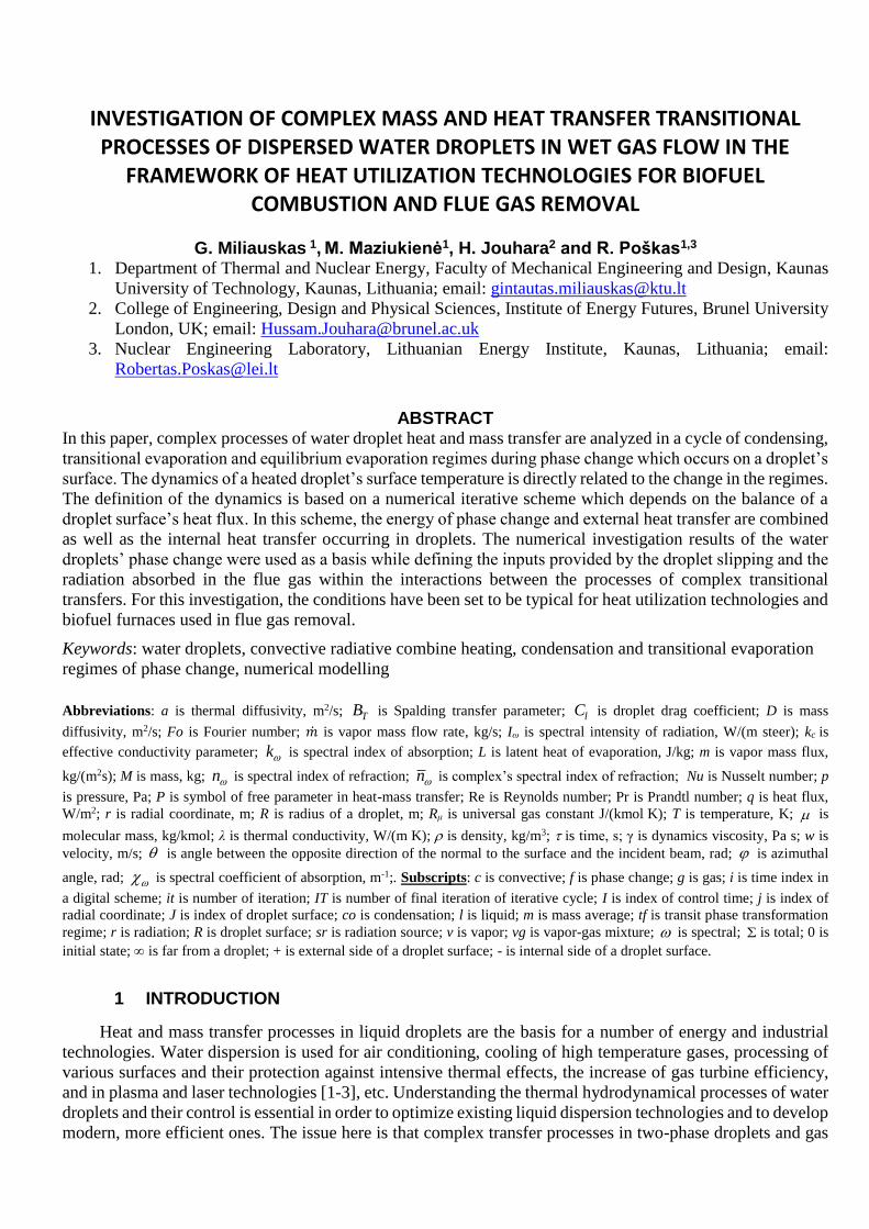
Fig. 3. Local radiation flux in droplets (a) and the variation of the Reynolds number (b). :srT (7) 0, (8) 1;
:m,1060 R (1) 10, (2) 25, (3) 50, (4) 100, (5) 250, (6) 500; :kW/m, 2
,Rrq (1) 39.77, (2) 53.78, (3) 63.64,
(4) 71.31, (5) 77.93, (6) 81.19; :K,0,lT (a) 306, (b) 358; m/s650, lw ; K1133gT ; m/s15gw ;
2.0vp .
The specific features of the variation in energy state of cold water droplets in humid air are clearly
displayed in the Fig. 2 b diagram for heat flux variation at the surface of a droplet of 200 μm diameter. In the
condensation regime, the initial energy impulse to the droplets is very strong and is defined by the sum of the
calculated of initial convective (1348.56 kW/m2) and condensation (227.11 kW/m2) heat flux. In the process
of the condensation regime, the condensation heat flux drops to zero. Hence, the convective heat flux to a
droplet and the convective heat flux within the droplet become equal at the moment co of phase change from
condensation to evaporation regime, and the calculated heat flux in this case is 1192.09 kW/m2 (Fig. 2 b, the
intersection of curves 7 and 8). Two characteristic periods can be distinguished when analyzing the specific
features of the convective heat flux qc,l variation in the transitional phase change regime. In the first period,
qc,l consistently reaches a zero value, while in the second period it increases and equals the value qr,e=69.4
kW/m2 of the absorbed radiation flux in the droplet at the moment e (Fig. 2 b, the second intersection of
curves 8 and 10). At the end of the first period, the temperature gradient in a droplet reaches a zero value (Fig.
2 a, curves 2 and 4) and it changes in direction. The temperature field of the negative gradient forms conditions
for the radiation heat absorbed in the droplet to flow to the surface of the droplet by internal convection and
to participate in the process of water surface evaporation. At the end of the second period, the temperature
gradient in the droplet ensures the full extraction of the absorbed radiation flux to the droplet’s surface and
participation in the water evaporation process. Hence, the calculated qc,l and qr at the moment e are equal and
eregcelcegcef qqqqq ,,,,,,, . At the beginning of the equilibrium evaporation, the increase of qc,l is
defined by the cooling droplet enthalpy. Later, when the cooling of the droplet decreases asymptotically (Fig.

1, curve 4), qc,l starts to decrease also, and the specific features of radiation flux absorption in the droplet,
diminishing due to evaporation, become more relevant to its further dynamics 1, Foq lc (Fig. 3 a). Thus, the
factors relevant to the droplet energy variation are the process of radiation absorption in semi-transparent
droplets and droplet slipping dynamics in the air flux. The droplet slipping dynamics have influence on the
Reynolds number variation that defines the intensity of the external convective heating (Fig. 3 b). A droplet
slipping quickly diminishes in the transitional phase change regime due to resistance forces, and radiation has
no significant influence on that (Fig. 3 b). Hence, the intensities qc,g,c and qc,g,cr of the convective heat fluxes
for the droplets with the same diameter are similar in the transitional phase change regime, while in the case
of complex heating at the end stage of equilibrium evaporation, qc,g,cr starts to increase faster (Fig. 4 a) due to
the quicker diminishing of more intensively evaporating droplets (Fig. 5 a).
0
300
600
900
1200
1500
1800
2100
2400
2700
3000
3300
3600
0 0.5 1 1.5 2 2.5 3 3.5 4 4.5 5
qcg,
kW
/m2
Fo
1 2
3 4
5 6
a)
0
20
40
60
80
100
120
140
160
0 0.5 1 1.5 2 2.5 3 3.5 4 4.5
qcl, k
W/m
2
Fo
1 2
3 4
5 6
b)
Fig. 4. The dynamics of the convective heat flux to the droplets (a) and within the droplets (b). :kW/m, 20,,gcq
(1, 2) 3548.05, (3, 4) 1348.56, (5, 6) 13.758; :kW/m, 20,fq (1, 2) 908.44, (3, 4) 227.11, (5, 6) 59.994;
:kW/m, 20,,lcq (1, 2) 4456.49, (3, 4) 1575.67, (5, 6) 46.236; :kW/m, 2
0,rq (1, 3, 5) 0, (2) 53.78, (4) 71.31,
(6) 84.13. Symbols are the same as in Fig. 1.

0
0.1
0.2
0.3
0.4
0.5
0.6
0.7
0.8
0.9
1
1.1
0 0.5 1 1.5 2 2.5 3 3.5 4 4.5 5
R/R
0
Fo
1 2
3 4
5 6
a)
0.998
0.999
1
1.001
1.002
1.003
1.004
1.005
1.006
1.007
0 0.05 0.1 0.15 0.2 0.25 0.3
R/R
0
Fo
1 2
3 4
5 6
b)
Fig. 5. The dynamics of droplet relative diameter R/R0 in the phase change cycle (a) and in the process of
transitional phase change (b). Rmax/R0: (1) 1.00636, (2) 1.00641, (3) 1.00474, (4) 1.00443, (5, 6) 1. Symbols
are the same as in Fig. 1.
0
500
1000
1500
2000
2500
3000
3500
0 0.25 0.5 0.75 1 1.25 1.5 1.75 2
Pe
Fo
1 2
3 4
5 6
1, 2
3, 4
5, 6 a)
0.75
1
1.25
1.5
1.75
2
2.25
2.5
2.75
0 0.25 0.5 0.75 1 1.25 1.5 1.75 2 2.25
kc
Fo
1
2
3
4
5
6
b)
Fig. 6. Droplet slipping influence on the Peclet number (a) and on effective thermal conductivity parameter
(b). Symbols are the same as in Fig. 1.
At the initial stage of the transitional phase change regime in an air flow, the droplets of cold water of
temperature 306 K increase in size while the warming water is expanding, and while water vapor is condensing
on their surfaces (Fig. 5 b, curves 1–4). At the beginning of transitional evaporation, the water expansion effect
is still stronger than the diminishing effect of the evaporating droplet. The dimensions of the droplet are the
largest at the moment these effects become equal. In dry air of high temperature, droplets start to diminish

immediately (Fig. 5, curves 5, 6). In the case of complex heating, the variation of the thermal state of the
central layers of the droplets (Fig. 2 a) is determined by the processes of water circulation and radiation
absorption. Water circulation is defined by the friction forces at the surfaces of slipping droplets. Their
intensity is assessed based on the Peclet number (Fig. 6 a), which describes the effective thermal conductivity
parameter (Fig. 6 b), which is an expression of the dominance of convection within a droplet compared to
thermal conductivity. As the droplet slipping diminishes, the convective thermal transfer becomes weaker and
12Fo ck (Fig. 6 b). For this reason, the heat within droplets is transferred via conductivity from Fo > 2
and via conductivity and radiation in the case of complex heat transfer. The distribution of local radiation flux
in droplets is non-linear and depends heavily on droplet dispersity (Fig. 3 a). The most intensive absorption of
radiation in large droplets occurs on the surface layers. As the droplets diminish through the evaporation
process, a stronger influence is from non-linear spectral optical effects on the surfaces of the droplets, and the
radiation absorption process changes under their influence (Fig. 3, curves 1–4). Essential changes in the
intensity of radiation absorption are observed at the last stage of the equilibrium evaporation regime when the
droplets are diminishing in size quickly. The qualitative change in the process of radiation flux absorption is
clearly displayed in the dynamics of convective heat flux in the droplet in the second part of the equilibrium
evaporation regime (Fig. 2 b, curve 8). In order to define the influence of radiation absorption effects, more
extensive and detailed research is necessary within the range of wide boundary conditions.
In the utilization process of the thermal energy of biofuel flue gas, the temperature of the flue gas
decreases monotonically to the temperature of the flue gas exhausted to the atmosphere. As the temperature
of the flue gas decreases, the role of radiation becomes less significant for the condition of complex transfer
processes. To highlight the tendencies, a cycle of the phase change has been modeled in water droplets
dispersed into the air flow of the intermediate temperature 678 K between the temperatures of a furnace and
the biofuel flue gas exhaust. In the case of conventional technologies, the humidity of cooling flue gas does
not change; therefore, the average humidity of 2.0vp normal to the flue gas of a biofuel furnace has been
preserved. In the flue gas of a lower temperature, the droplets start the equilibrium evaporation at a lower
temperature (Fig. 7), but the influence of the transitional phase change condensation regime increases (Fig. 8).
315
320
325
330
335
340
345
350
355
0 2 4 6 8 10 12 14
TR
, K
Fo
1 2 3
4 5 6
1, 2
a)
315
320
325
330
335
340
345
350
355
0 1 2 3 4 5 6 7 8
Tm
, K
Fo
1 2 3
4 5 6
1, 2
b)
Fig. 7. The influence of the dispersity and heating process on the variation of the surface temperature of water
droplets (a) and the variation of mass average temperature (b) in the air flow of 678 K temperature.
:m,1060 R (1, 2) 50, (3, 4) 100, (5, 6) 1600; :srT (1, 3, 5) 0, (2, 4, 6) 1; :Re0 (1, 2) 49.4, (3, 4) 246.98, (5,

6) 0; :K,0,lT (1-4) 306, (5, 6) 358; m/s,0,lw : (1-4) 65, (5, 6) 0; m/s,gw : (1-4) 15, (5, 6) 0; K1133gT ;
vp : (1-6) 0.2, (7, 8) 0; :/ 200 Ra (1, 2) 53.572, (3, 4) 2.14288, (5, 6) 0.052316.
In the dry air flow of 678 K temperature, the droplets of 358 K temperature satisfy the warm water condition
10, lT , irrespective of their heating process. In the case of conductive heating, the droplets cool down to
326.14 K temperature (Fig. 7, curve 5) at the initial evaporation stage, while in the case of complex heating,
the droplets approach this temperature at the final evaporation stage (Fig. 7, curve 6). In the humid air flow of
temperature 678 K, the droplets of 306 K temperature satisfy the cold water condition 10, lT and, in the
transitional phase change regime, warm up to the highest equilibrium evaporation temperature 347.5, 347.55,
349.79 and 350.5 K calculated for the boundary conditions (1–4), respectively, defined in Fig. 7.
0
0.1
0.2
0.3
0.4
0.5
0.6
0.7
0.8
0.9
1
1.1
0 2 4 6 8 10 12 14
R/R
0
Fo
1 2
3 4
5 6
a)
0.998
1
1.002
1.004
1.006
1.008
1.01
1.012
0 0.1 0.2 0.3 0.4 0.5 0.6 0.7 0.8 0.9
R/R
0
Fo
1 2
3 4
5 6
1, 2
5, 6 b)
Fig. 8. The dynamics of the relative R/R0 diameter of the water droplets warming up in the 678 K air flow in
the phase change cycle (a) and in the process of transitional phase change (b). Rmax/R0: (1) 1.00636, (2)
1.00641, (3) 1.00474, (4) 1.00443, (5, 6) 1. Symbols are the same as in Fig. 7.
0.998
1
1.002
1.004
1.006
1.008
1.01
1.012
1.014
1.016
1.018
1.02
1.022
0 0.1 0.2 0.3 0.4 0.5 0.6 0.7
M/M
0
Fo
1 2
3 4
5 6
a) 0
0.03
0.06
0.09
0.12
0.15
0.18
0.21
0.24
0.27
0.3
0.33
0.36
0.39
0.42
0 1.5 3 4.5 6 7.5 9 10.5 12 13.5m
, kg/(
s m
^2)
Fo
1 2
3 4
5 6
1, 2
b)
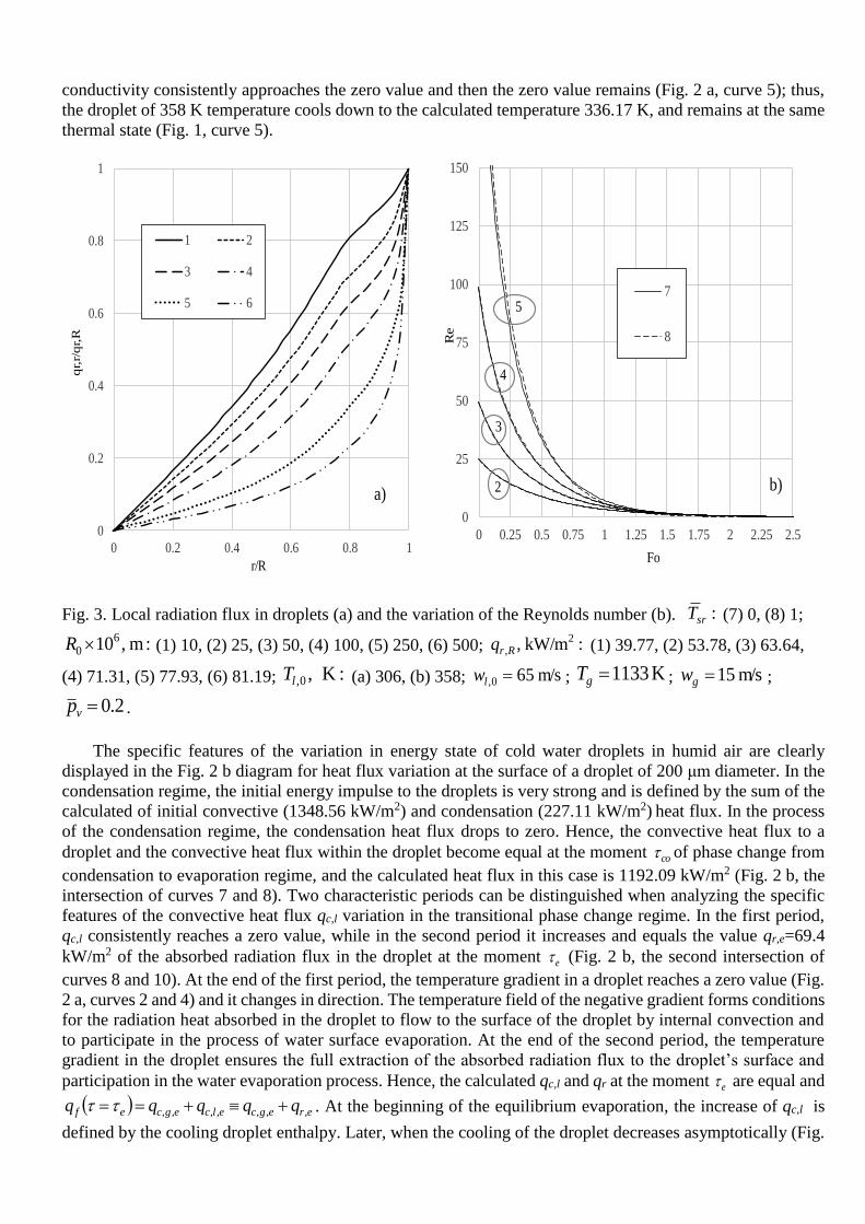
Fig. 9. The variation of the relative M/M0 mass of the water droplets warming up in the 678 K air flow in the
transitional phase change regime (a) and the variation of vapor mass flux in the phase change cycle (b) in the
process of transitional phase change. Mmax/M0: (1) 1.02085, (2) 1.02093, (3) 1.01289, (4) 1.01242, (5, 6) 1;
mv,0, kg/(m2s) : (1, 2) 0.2253, (3. 4) 0.05633, (5, 6) 0.01522. Symbols are the same as in Fig 7.
0
0.1
0.2
0.3
0.4
0.5
0.6
0.7
0.8
0.9
1
1.1
1.2
1.3
0 0.1 0.2 0.3 0.4 0.5 0.6 0.7 0.8 0.9 1
qcl/
qcg
Fo/Fof
1 2
3 4
a)
0
0.1
0.2
0.3
0.4
0.5
0.6
0.7
0.8
0.9
1
1.1
1.2
1.3
0 0.1 0.2 0.3 0.4 0.5 0.6 0.7 0.8 0.9 1
qf/
qcg
Fo/Fof
1 2
3 4
b)
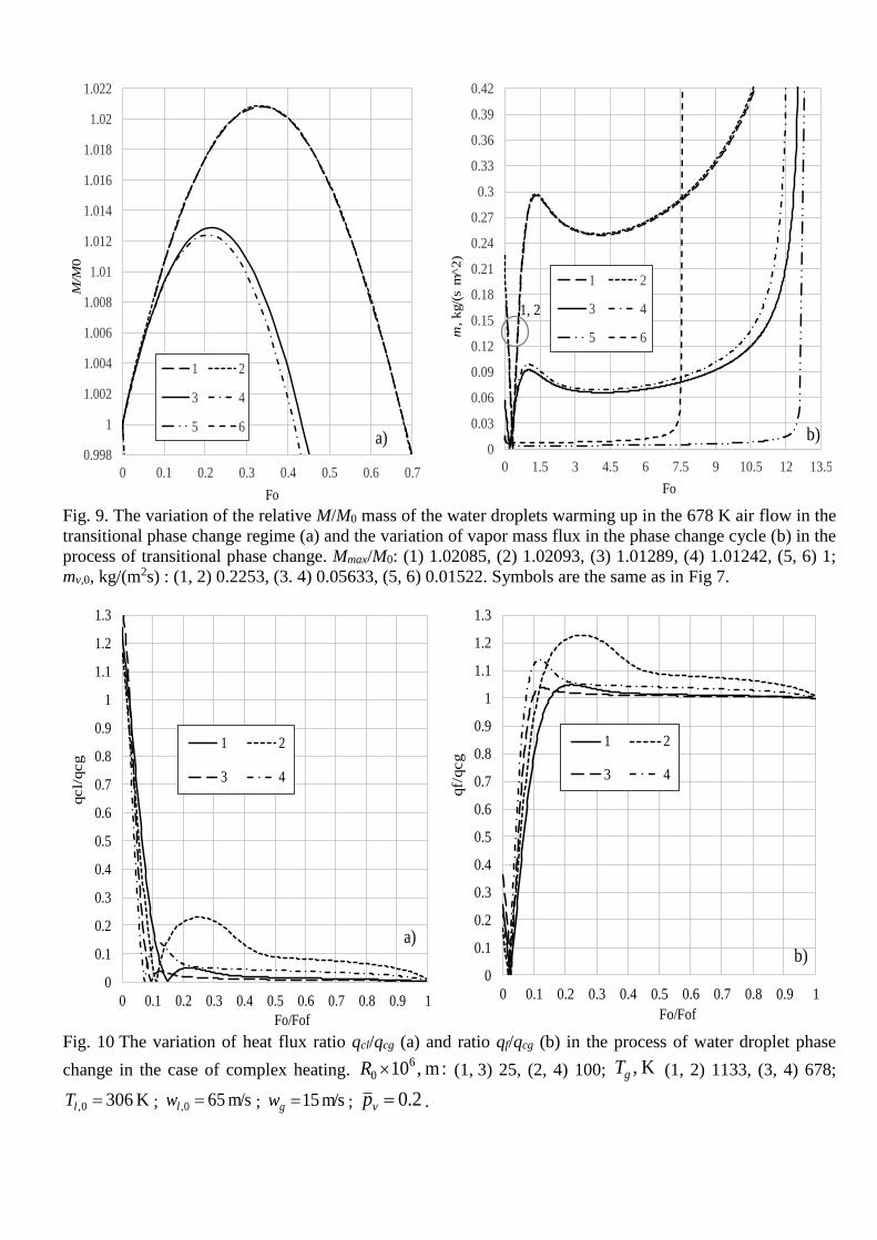
Fig. 10 The variation of heat flux ratio qcl/qcg (a) and ratio qf/qcg (b) in the process of water droplet phase
change in the case of complex heating. :m,1060 R (1, 3) 25, (2, 4) 100; K,gT (1, 2) 1133, (3, 4) 678;
K3060, lT ; m/s650, lw ; m/s15gw ; 2.0vp .

0
0.02
0.04
0.06
0.08
0.1
0.12
0.14
0 0.2 0.4 0.6 0.8 1
qr/
qcg
Fo/Fof
1 2
3 4
a) 0
0.5
1
1.5
2
2.5
3
3.5
4
4.5
5
5.5
6
6.5
7
0 0.1 0.2 0.3 0.4 0.5 0.6 0.7 0.8 0.9 1
qr/
qcg
Fo/Fof
5
6
b)
Fig. 11. The variation of heat flux ratio qr/qcg in the process of water droplet phase change in the case of
complex heating. :m,1060 R (1, 3) 25, (2, 4) 100, (5) 1500, (6) 1600; K,gT (1, 2, 5) 1133, (3, 4, 6) 678;
:K,0,lT (1-4) 306, (5, 6) 358; m/s,0,lw : (1-4) 65, (5, 6) 0; m/s,gw : (1-4) 15, (5, 6) 0; 2.0vp .
The calculated durations e of the transitional phase transition regime e to0 for cases (1–4) are
0.00598, 0.00621, 0.0729 and 0.077 s, respectively, and the calculated duration co of the condensation regime
in it is quite clear and is 0.00156, 0.00156, 0.016 and 0.0154 s, respectively. For the cases modeled, the radii
of cold water droplets increased to 25.266, 25.267, 100.787 and 100.77 µm respectively, in the condensation
regime and at the beginning of the equilibrium evaporation. Therefore, the radii of small droplets increased by
more than 1 percent (Fig. 8 b), and their mass increases by more than 2 percent in the condensation regime
(Fig. 9 a).
The variation of the water droplets’ thermal and energy state is defined by the heat flux dynamics on the
droplet’s surface. In order to describe the specificity of the dynamics mentioned, the dynamics of non-
dimensional heat fluxes qcg/qn qr/qn, qcl/qn, and qf/qn expressed via the heat flux ratio nqqq / is important.
When choosing a normalizing heat flux qn, the goal must be taken into account. Heat flux qcg is convenient to
use as a normalizing heat flux qn when aiming to highlight the change of the complex heat flux relationship
since it does not obtain a negative value in the process of the droplet phase change (Fig. 4 a). The dynamics
of the relation between heat fluxes qcl/qcg (Fig.10 a) describes the input of the complex heating process
components into the change of the droplets’ thermal state. At the initial stage of the phase change 1clq ,
therefore this relation indicates the additional input of condensation heat. The input of the absorbed radiation
should also be considered; in this case it is indicated by rq (Fig. 11 a). At the moment the condensation regime
changes to evaporation 1 kocl FoFoq and from this moment on, the water within the droplet is heated by
the absorbed radiation and the convective heat that does not participate in water surface evaporation. At the
time 0Foqcl , all convective heat participates in the water evaporation process. Later, a part of the absorbed
radiation, which was directed to the surface by internal convection, starts to participate in the evaporation
process. The condition erecl FoFoqFoFoq indicates the start time Foe of the equilibrium evaporation,
and later the proportion between erecl FoFoqandFoFoq is defined by the cooling droplet enthalpy joining
the water evaporation process and the qualitative change of the radiation local heat flux at the final stage of
evaporation. The dynamics of the relation between heat fluxes qf/qcg (Fig. 10 b) describes the specific features

of the change in energy origin of the heat participating in the phase changes at the droplets’ surfaces. In order
to evaluate the dynamics of the heat flux at the droplet’s surface, it is convenient to consider the dynamics of
the parameters 0/ qFoqFoq defined by heat flux time functions q(Fo) and the initial heat flux relation
(Fig. 12 and 13). The following functions define such universal qualitative diagrams of the droplet phase
change process variation: function 0,/ cgcgcg qFoqFoq describes the variation of convection heat flux (Fig.
12 a); function Foqcl describes the variation of convective heat flux in a droplet (Fig. 12 b); function Foq f
the variation of the phase change heat flux at the surface of the droplet; function Foqr describes the variation
of the radiation heat flux absorbed in a semi-transparent droplet.
0.2
0.4
0.6
0.8
1
1.2
1.4
1.6
1.8
0 0.1 0.2 0.3 0.4 0.5 0.6 0.7 0.8 0.9 1
qcg/q
cg0
Fo/Fof
1 2
3 4
a) 0
0.2
0.4
0.6
0.8
1
0 0.1 0.2 0.3 0.4 0.5 0.6 0.7 0.8 0.9 1
qcl/
qcl0
Fo/Fof
1 2
3 4
b)
Fig. 12. The variation of qcg/qcg,0 ratio (a) and qcl/qcl,0 ratio (b) of heat flux in the process of water droplets
phase change in the case of complex heating. :m,1060 R (1, 3) 25, (2, 4) 100; K,gT (1, 2) 1133, (3, 4) 678;
K3060, lT ; m/s650, lw ; m/s15gw ; 2.0vp .

0
0.5
1
1.5
2
2.5
3
3.5
4
4.5
5
0 0.1 0.2 0.3 0.4 0.5 0.6 0.7 0.8 0.9 1
qf/
qf0
Fo/Fof
1 2
3 4
a) 0
0.1
0.2
0.3
0.4
0.5
0.6
0.7
0.8
0.9
1
0 0.1 0.2 0.3 0.4 0.5 0.6 0.7 0.8 0.9 1qr/
qr0
Fo/Fof
1 2
3 4
b)
Fig. 13. The variation of qf/qf,0 ratio (a) and qr/qr,0 ratio (b) of heat flux in the process of water droplets phase
change in the case of complex heating. :m,1060 R (1, 3) 25, (2, 4) 100; K,gT (1, 2) 1133, (3, 4) 678;
K3060, lT ; m/s650, lw ; m/s15gw ; 2.0vp .
0
0.05
0.1
0.15
0.2
0.25
0.3
0.35
0.4
0 2 4 6 8 10 12
g 1
0^
7,
kg/s
Fo
1 2
3 4
5 6
7 8
1, 2
5, 6
a)
3,4
7, 8
m
0
1
2
3
4
5
6
7
8
9
0 2 4 6 8 10 12
g 1
0^
7,
kg/s
Fo
9 10
11 12
b)
Fig. 14. Vapor flow rate at the surfaces of small and average size (a) and large (b) droplets dependency on the
heating process: (1, 3, 5, 7) convective heating, (2. 4, 6, 8) complex heating – convection and radiation, (9,
11) conductive heating, (10, 12) complex heating – conduction and radiation; :kg/s107
0,m (1, 2) 0.0294, (3,
4) 0.1178, (5, 6) 0.0177, (7, 8) 0.0708, (9, 10) 7.388, (11, 12) 4.896; :m,1060 R (1, 2, 5, 6) 25, (3, 4, 7, 8)
m

100; (9, 10) 1500, (11, 12) 1600; K,gT (1-4, 9, 10) 1133, (5-8, 11, 12) 678; K,0,lT : (1-8) 306, (9-12) 358;
:vp (1-8) 0.2, (9-12) 0; :m/s,0,lw (1-8) 65, (9-12) 0; :m/s,gw (1-8) 15, (9-12) 0.
0
0.1
0.2
0.3
0.4
0.5
0.6
0.7
0.8
0.9
1
1.1
1.2
1.3
1.4
0 1 2 3 4 5 6 7 8 9 10 11 12 13 14
mv ,
kg/(
s m
^2)
Fo
1 2
3 4
5 6
7 8
1, 2
5, 6
a)
7, 8
3, 4
0
0.005
0.01
0.015
0.02
0.025
0.03
0.035
0.04
0.045
0.05
0.055
0.06
0.065
0.07
0.075
0.08
0 1 2 3 4 5 6 7 8 9 10 11 12 13 14
mv ,
kg/(
s m
^2)
Fo
9
10
11
12
b)
Fig. 15. Vapor flux at the surfaces of small and average size (a) and large (b) droplets dependency on the
heating process. :) skg/(m 2
0,m
,g (1, 2) 0.3748, (3, 4) 0.0937, (5, 6) 0.2253, (7, 8) 0.0563, (9, 10) 0.02613,
(11, 12) 0.01522. Boundary conditions as in Fig. 14.
The characteristics of droplet thermal and energy states as well as phase change determined by the
interaction of complex transfer processes define the parameter for water vapor flow rate �̇�𝑣, kg/s at the droplet
surface, which is important to water dispersion technologies. The intensity of vapor flow is defined by vapor
flux mv kg/(m2s). The vapor flow rate at the surfaces of the droplets approaches the zero value from the initial
value �̇�𝑣,0 in the process of phase change when the droplets evaporate (Fig. 14), and the vapor flux increases
quickly at the final stage of evaporation (Fig. 15). The initial vapor flux is defined by the temperature of the
dispersed water, the droplet dispersity, and the air humidity. In the condensation regime, the vapor flux at the
surface of cold water droplets decreases to zero, while in the transitional regime, it increases to the value mv,e,
which is also influenced by the droplet heating process. At the beginning of equilibrium evaporation, mv,e,
kg/(s m2) is 0.8724, 0.8995, 0.2815, 0.3274, 0.2951, 0.2973, 0.09192 and 0.0985 for boundary conditions (1–
8), respectively (Fig. 15 a). At the beginning of the equilibrium evaporation, the vapor flow rate �̇�𝑒.107, kg/s
is 0.0615, 0.0614, 0.3171, 0.3455, 0.0221, 0.02212, 0.1097 and 0.1158, respectively (Fig. 14 b). Warm water
droplets instantly reach equilibrium evaporation and in their case �̇�𝑒≡�̇�0 (Fig. 14 b) and mv,e≡mv,0 (Fig. 15 b).
At the initial stage of equilibrium evaporation, the increase in vapor flow rate is defined by the enthalpy of the
cooling droplets participating in the water evaporation process; however, it is also suppressed by the
weakening intensity of the convective heating, which is defined by the decrease in droplet slipping. The
increase of the vapor flow rate is also directly defined by the decrease of the droplet’s surface area. The result
of these factors is the extreme points formed in the diagrams of the vapor flux variation, and the rapid increase
in the vapor flow rate at the final stage of droplet evaporation is defined by the decrease of the droplets’ surface
area.
The equilibrium evaporation velocity of the large water droplets was experimentally investigated in [17] in
the case of complex heating. The experiment was performed in an original test section where the water was
fed into the centre of a chamber heated up to a temperature of 405–860 0C via a capillary system. An
evaporating water droplet of 600–2900 μm diameter was formed at the outlet of a 3 mm diameter copper

capillary tube. The droplet was heated by the radiation from the chamber walls and the convective heat of the
air-water vapor mixture flowing around the chamber was extracted. The extraction of the air-water vapor flow
helped to satisfy the condition necessary to the flow regime so that the calculated Reynolds number Re<3. The
water feeding the evaporating droplet was heated to such a temperature that an additional 25–30 0C from the
capillar would not change the droplet temperature measured by a thermocouple. After ensuring the stability of
the 30–50 times enlarged projection of the illuminated droplet on a screen, the velocity of the droplet
evaporation was assumed to be the measured feed water flow rate [17]. The experimental results have been
compared to the modeling results of large water droplet evaporation in 1133K and 678 K temperature
environments in the dependence of the equilibrium evaporation intensity �̇�𝑒 on their radius (Fig. 16 a). The
diagrams of functions Rm were drawn based on the functions FoR (Fig. 16 b) calculated during the
modeling of the droplet evaporation process and based on the evaporation intensity i
m calculated for
corresponding iFo moments in time; the experimental points were taken based on results from the work in
[17].
0
1
2
3
4
5
6
7
8
9
10
11
0.4 0.5 0.6 0.7 0.8 0.9 1 1.1 1.2 1.3 1.4 1.5 1.6
g1
0^
7,
kg/s
R/1000, μm
1 2
3 4
5 6
7 8
b)
0
150
300
450
600
750
900
1050
1200
1350
1500
1650
0 1.5 3 4.5 6 7.5 9 10.5 12 13.5
R, μ
m
Fo
1 2
3 4
a)
Fig. 16. The influence of the heating process on the vapor flow of large water droplets at their surfaces (a) and
for the radius dynamics (b): (1, 3) conductive heating, (2, 4, 7) complex heating – conduction and radiation,
(5, 6, 8) complex heating – conduction radiation and weak convection; :m,1060 R (1, 2, 7, 8) 1500, (3, 4)
1600; K,gT (1, 2, 6-8) 1133, (3-5) 678; :K,0,lT (1-4) 358, (5, 6) Te, (7, 8) 362; 0Re (1-4, 7) 0, (5, 6) 3Re
[17], (8) 1.7; 0vp ; the lines represent the modeling results; the points represent the experimental results
[17].
While modeling the experimental boundary conditions, the temperature of the radiation source Tsr was
assumed to be equal to the air temperature Tg. However, the initial droplet temperature Tl,0 was estimated
intuitively, and there were still the uncertainties considering the humidity of the air-water vapor flow extracted
from the chamber and the droplet flow regime. During the experiments, the air humidity was not set. During
the modeling, the assumption 0vp was used. In the modeling, the possible experimental droplet flow regimes
were defined with boundary values 0Re min,0 and 3Re max,0 for the Reynolds number vgggwR /2Re . When
modeling the evaporation of a conductively heated droplet (Fig. 16 a, curves 1, 3), 0Re0 and Tsr=0; in the
m

case of complex heating with conductivity and radiation (Fig. 16 a, curves 2, 4, 7), 0Re0 and Tsr=Tg; in the
case of complex heating with convection and radiation (Fig. 16 a, curve 8) 7.1Re0 and Tsr=Tg.
At first, the modeling results were compared with the afore-mentioned calculated evaporation mass flow
rate of the modeled large 358 K temperature water droplets, heating them using conduction, and in the case of
complex heating (Fig. 16, curves 1–4, points 5, 6). The droplet heating process had a strong influence on their
evaporation intensity. At the relatively low 678 K temperature under the influence of radiation, the velocity of
droplet evaporation increases to twice the value from conductive heating (Fig. 16, curves 3 and 4). In this case,
the water droplets of 358 K temperature cool down quickly to the equilibrium evaporation temperature, and
after that the diagram of the function RmmR,e
defining their evaporation intensity variation practically
coincides with the experimental results (Fig. 16, curve 4 and 5 points). For the high temperature of 1133 K in
the radiation environment, the equilibrium evaporation of large droplets is more rapid by several times
compared to the evaporation of conductively heated droplets (Fig. 16, curves 1 and 2). In the case of complex
heating, the water droplets of 358 K temperature warm up at first, and their evaporation intensity increases to
that for equilibrium evaporation; however, the diagram curve R,e
m is a little lower compared to the experimental
results (Fig. 16, curve 2, data points 6). The water droplets of 362 K temperature evaporate in the equilibrium
manner, and their curve for R,e
m in the diagram is closer to the experimental results; however, the level of
experimental results is not reached for the droplets larger than 1.5 mm diameter (Fig. 16, curve 7, data points
6). In the case of heating with convection ( 7.1Re0 ) and radiation, the water droplets of 362 K temperature
warm up rapidly to the equilibrium evaporation temperature. After that the function R,e
m for their mass flow
rate practically coincides with the experimental results (Fig. 16, curve 8, data points 6).
4 CONCLUSIONS
Condensation, transitional evaporation and equilibrium evaporation regimes are clearly noticed in the wet
gas flow in the process of water droplet phase change. The characteristics of dispersed water phase changes
are defined by the specific features of droplet thermal and energy state change. In the transitional phase change
regime, they are defined by the temperature of the dispersed water, and at the equilibrium evaporation regime,
the factors of gas temperature and humidity are important.
When the temperature of the dispersed water is lower than the dew point, the cycle of droplet phase change
starts with the condensation regime. The duration of the condensation regime is clearly defined by the droplet’s
warm up to the dew point temperature. The end of the transitional phase change regime is defined based on
water droplet warming up to the thermal state that ensures equilibrium evaporation; it is defined by temperature
elT , . The process of droplet heating plays an important role when defining the equilibrium evaporation
temperature elT , . In the case of convective heating, temperature elT , is defined by the instantaneous highest
temperature max,RT of the droplet’s surface, while in the case of complex heating it is the average instantaneous
highest temperature max,mT of the droplet’s mass.
The parameter elll TTT ,0,0, / which is expressed through the ratio of water temperature and droplet
equilibrium evaporation temperature defines the thermal state variation of droplets. When 10, lT , the water is
assumed to be relatively cold, and its droplets warm up to temperature elT , in the transitional phase change
regime. When 10, lT , the water is assumed to be relatively warm, and its droplets cool down during
equilibrium evaporation.
The droplet energy state variation is defined by the dynamics of the heat fluxes at the droplet’s surface
for which the parameter nq expressed through heat flux ratios qcg/qn qr/qn, qcl/qn, qf/qn is important. The
normalizing heat flux qn is chosen based on the goal of the energy state assessment. The variation in
interrelation between heat fluxes becomes clear when the heat flux qcg obtaining no negative value in the
process of the droplet phase change is used instead of normalizing heat flux qn. The common characteristics
of heat flux variation become clear in the droplet phase change regimes when the initial heat flux q0 are used
instead of normalizing parameter qn.

When water is dispersed into the high temperature flue gas of a biofuel furnace, the heating of the droplets
is defined by radiation and droplet slipping factors. Traditional technologies of flue gas heat utilization cool
down the flue gas, yet the flue gas temperature before a condensing shell and tube heat exchanger is higher
than the dew point temperature and the humidity is still high. For this reason, the thermal state of the
equilibrium evaporation of the dispersed droplets is defined by the humidity of the flue gas, and the
condensation regime duration in the transitional phase change regime becomes more significant. The effect of
the radiation of a relatively low temperature in the flue gas on the transfer processes becomes weaker, and the
droplet slipping factor becomes more significant. A higher slipping velocity of droplets means more intensive
convective heating; however, the water circulation in the droplets is more intensive due to friction forces, and
therefore heat removal to the centre of the droplet intensifies. This gives the necessary conditions for the
diminishing of the warming up of the droplet surface and for the duration of the condensation regime to become
longer, which is convenient when talking about the increased efficiency of the utilization of phase change heat
from the biofuel flue gas.
REFERENCES
[1] A Abdel-Salam A. H., Simmson J. C., State-of-the-art in liquid desiccant air conditioning equipment and systems,
Renewable and Sustainable Energy Reviews, Vol 58, pp. 1152-1183, 2016.
https://doi.org/10.1016/j.rser.2015.12.042 [2] Bucklin J. M., Mitigation of industrial hazards by water spray curtains, Journal of Loss Prevention in the Process
Industries, Vol. 50, pp. 91-100, 2017. https://doi.org/10.1016/j.jlp.2017.08.007
[3] Paepe W., Carrero M., Bram S., Contino F., Parente A., Waste heat recovery optimization in micro gas turbine
applications using advanced humidified gas turbine cycle concepts, Applied Energy, Vol. 207, pp. 218-229, 2017. https://doi.org/10.1016/j.apenergy.2017.06.001 [4] Hsieh S., Luo S., Droplet impact dynamics and transient heat transfer of a micro spray system for power electronics
devices, International Journal of Heat and Mass Transfer, Vol 92, pp 190-205, 2016.
https://doi.org/10.1016/j.ijheatmasstransfer.2015.08.099 [5] P. L. C. Lage, C. M. Hackenberg, R. H. Rangel, Nonideal Vaporization of Dilating Binary Droplets with Radiation
Absorption, Combustion and Flame, Vol. 101, pp. 36–44, 1995. https://doi.org/10.1016/0010-2180(94)00191-T
[6] L. A Dombrovsky, S. S Sazhin, E. M. Sazhina, G. Feng, M. R. Heikal, M. E. A. Bardsley, Heating and evaporation of
semi-transparent diesel fuel droplets in the presence of thermal radiation, Fuel, Vol. 80, pp. 1535–1544, 2001.
https://doi.org/10.1016/S0016-2361(01)00025-4 [7] G. Miliauskas, Regularities of unsteady radiative-conductive heat transfer in evaporating semi-transparent liquid
droplets, International Journal of Heat and Mass Transfer, Vol. 44, pp. 785–798, 2001. https://doi.org/10.1016/S0017-9310(00)00127-7 [8] C. C. Tseng, R. Viskanta, Enhancement of water droplet evaporation by radiation absorption, Fire Safety Journal, Vol.
41, pp. 236-247, 2006. https://doi.org/10.1016/j.firesaf.2006.01.001
[9]. M. Q. Brewster, Evaporation and condensation of water mist/cloud droplets with thermal radiation, International
Journal of Heat and Mass Transfer, Vol. 44, pp. 785–798, 2015.
https://doi.org/10.1016/j.ijheatmasstransfer.2015.03.055 [10] G. M. Hale, M. R Query, Optical constants of water in the 200-nm to 200-μm wavelength region, Applied Optics,
Vol. 12, pp. 555–562, 1973. https://doi.org/10.1364/AO.12.000555
[11] G. M. Hale, M. R Query, A.N. Rusk, D. Williams, Influence of temperature on the spectrum of water, J. Opt. Soc. Am.,
Vol. 62, pp. 1103–1108, 1972. https://doi.org/10.1364/JOSA.62.001103
[12] W. A. Sirignano, Fluid Dynamics and Transport of Droplets and Sprays, Cambridge University Press, p. 311, 1999.
[13] S. S. Sahin, Droplets and Sprays, Springer, p. 352, 2014.
[14] B. Abramzon, W. A. Sirignano, Droplet vaporization model for spray combustion calculations, International Journal
of Heat and Mass Transfer, Vol 32, pp 1605-1618, 1989. https://doi.org/10.1016/0017-9310(89)90043-4
[15] Miliauskas G., Maziukiene M., Ramanauskas V., Puida E., The defining factors of the phase change cycle of water
droplets that are warming in humid gas, International Journal of Heat and Mass Transfer, Vol 113, pp 683-703, 2017. https://doi.org/10.1016/j.ijheatmasstransfer.2017.05.129 [16] A. V. Kuzikovskij, Dynamics of spherical particle powerful optical field, Izv. VUZ Fizika, Vol. 5, pp. 89–94, 1970.
[17] V.M. Ivanov, E.V. Smirnova. Experimental research of liquid droplets evaporation velocity in non-moving high
temperature environment. Tr. IGI, Vol. 19, pp. 46-58, 1962.