investigation of effect of cutting parameters and tool ... · it is very complex to understand...
TRANSCRIPT

1
“Investigation of effect of cutting parameters and tool nose radius on cutting forces
and surface roughness in finish hard turning of AISI D2 steel with CBN tool”
Ph.D. Synopsis
Submitted To
Gujarat Technological University, Ahmedabad
For The Degree Of
Doctor of Philosophy
In
Mechanical Engineering
By
Vallabhbhai D Patel
Enrollment No: 129990919013
(Mechanical Engineering)
Supervisor:
Dr. Anishkumar H Gandhi
Principal, C K Pithawala College of Engineering and Technology, Surat, India.
Members of Doctoral Progress Committee:
(1) Dr. H. K. Raval
Professor, Mechanical Engineering Department,
S. V. National Institute of Technology, Ichchhanath, Surat-395007, Gujarat, INDIA
(2) Dr. D. I. Lalwani
Associate Professor, Mechanical Engineering Department,
S. V. National Institute of Technology, Ichchhanath, Surat-395007, Gujarat, INDIA

2
A. ABSTRACT
Because of its excellent wear and abrasion properties, AISI D2 steel is widely used as a material for
bearing races, forming dies, punches, forming rolls, etc. Understanding of the mechanics of oblique
turning of hardened materials is important to industries manufacturing components like bearings,
dies and tools. This research describes investigation of effect of cutting parameters (cutting speed,
feed), tool geometries (tool nose radius) on cutting forces (cutting force, radial force and axial force)
and surface roughness of AISI D2 steel using cubic boron nitride (CBN) tool. Experiments were
conducted based on full factorial design of experiment. Results shows influence of different cutting
conditions on cutting forces and surface roughness. Forces in axial, radial and cutting directions vary
with the different values of cutting speed, feed and nose radius at constant depth of cut during hard
turning. Initially, force model is developed based on cutting parameters (i.e. cutting speed and feed)
and tool nose radius and further it is extended by considering progressive flank wear. Empirical
model of cutting forces shows best fits with cutting conditions (i.e. cutting speed and feed) and tool
geometries (i.e. tool nose radius, inclination angle and rake angle). Experimental observation shows
that feed is most significant parameter affecting cutting force, radial force and axial force followed
by nose radius and cutting speed. Cutting forces are linearly proportional to feed and nose radius
whereas, it is inversely proportional to cutting speed. A linear exponential model of surface
roughness shows simultaneous effect of cutting speed, feed and nose radius. Feed contributes
significantly to surface roughness than tool nose radius and cutting speed. Empirical models of
forces and surface roughness are validated with new set of experiments and found to be with
reasonable accuracy of prediction within limits of cutting parameters and tool geometry considered.
B. BRIEF DESCRIPTION ON THE STATE OF THE ART OF THE RESEARCH TOPIC
Finish turning of materials with hardness above 45 HRC (Rockwell hardness) using CBN cutting
tool insert has produced better accuracy and reduced setup time in comparison to grinding process
[1]. CBN is preferred as a tool material for hard turning because of its specific properties like
inertness with ferrous materials and high hardness [2]. Hard turning is an oblique cutting process and
it is very complex to understand factors affecting the process. Wide variety of cutting conditions
along with geometries of cutting tool inserts has been used based on cutting forces and tool life.
Analysis of cutting forces is important as it has greater influence on the performance of hard turning
[3]. The orthogonal cutting process is easy to understand, but oblique cutting is more complex.
Researchers have modeled the cutting forces in three dimensions based on certain assumptions. Most
empirical models were developed based on friction and normal forces which comprises the shear
stresses and shear zone [4-6].
Surface roughness is one of the significant surface qualities of machined hardened steels which has a
specific application for manufacturing of bearings, shafts, tools and dies. Turning of materials having

3
hardness above 45 HRC is abbreviated as a hard turning. Hard turning using CBN cutting tool inserts
greatly reduces the machining time and improves surface finishing in comparison to grinding [7, 8].
Asiltürk and Çunkaş [9] reported modeling of surface roughness of AISI 1040 steel using multiple
regression and artificial neural networks (ANN) approach considering different cutting parameters
such as cutting speed, feed and depth of cut. Cutting parameters like cutting speed, feed, depth of cut
and tool geometry significantly affect the surface roughness of machined component. Singh and Rao
[10] analyzed the surface roughness using response surface methodology (RSM) based on cutting
conditions, tool nose radius and effective rake angle. RSM is also used by Aouici et al. [11] for
modeling of surface roughness as a function of cutting parameters and workpiece hardness.
Regression analysis is used for modeling of surface roughness as a function of cutting speed, feed
and depth of cut by many researchers [7, 12-14]. Research reported in literatures shows that surface
roughness decreases with reduction of depth of cut [7, 15-17]. They concluded that lower surface
roughness value can be achieved using smaller value of depth of cut (0.2 mm). Evaluation of cutting
forces and surface roughness of machined component is very important for any oblique cutting
theory for proper prediction based on affected cutting conditions.
Forces exerted on tool in three directions (i.e. in cutting, radial and axial directions) draw specific
attention. Here, models of cutting forces are developed based on effect of variable cutting speed, feed
and different nose radius of CBN tool. In addition, implementation of progressive flank wear during
hard turning enhances the effectiveness of three dimensional force models. Various literatures
describe model of surface roughness pertaining to effect of some cutting conditions or certain
geometries while this work shows simultaneous effect of all variable cutting conditions like cutting
speed, feed and tool nose radius on machined surface roughness during hard turning which can be
extended as per cutting environment. Moreover, effect of different tool nose radius on cutting forces
and surface roughness of machined AISI D2 steel having average hardness of 57 HRC represents
novelty of this research.
C. DEFINITION OF THE PROBLEM
Since decades of research in the turning process, different theories and mechanisms are continuously
modified and developed for enhancing accuracy of prediction of surface roughness and cutting forces
based on different cutting parameters. Orientation of cutting forces during finish hard turning is very
difficult to describe. It is necessary to describe complex oblique cutting into simplified phenomenon
which shows functional relation of three dimensional cutting forces and all possible cutting variables
for effective prediction. Moreover, cutting speed, feed and nose radius of different CBN tools (Here,
depth of cut constant 0.2 mm) have some significant contribution to generate surface roughness of
hardened AISI D2 steel. So, critical part of model generation of surface roughness is to inculcate the
simultaneous effect of cutting speed, feed and tool nose radius for effective prediction.

4
D. OBJECTIVE AND SCOPE OF WORK
Objectives:
To perform experimental investigation for optimizing the machining parameters and tool nose
radius for minimizing tool forces and surface roughness in hard turning of AISI D2 steel using
CBN tool.
To develop the model for prediction of three dimension forces as a function of machining
parameters, nose radius and tool angles.
To enhance accuracy of force model by including the effect of progressive flank wear of CBN
tool measured at optimum cutting conditions during hard turning and validate that model with
experimental results.
To develop model of surface roughness of machined part which includes simultaneous effect of
all possible factors during hard turning.
Scope of work:
There is a major difference in tooling and mechanism use in turning of materials in hardened and
normal condition. Hard turning is performed for manufacturing of specific high pressure dies,
tools, automotive and hydraulic parts for high accuracy, finishing and more productivity. Various
cutting conditions along with tool geometries affect surface finish of machined part. From this
work, manufacturers of various components which are made from AISI D2 steel can get
complete details of effect of variation of cutting conditions and tool geometries on surface
roughness. So, optimum cutting conditions can be obtained based on their requirement of surface
roughness of AISI D2 steel.
This work is also helpful to design CBN tool considering effect of tool geometries like tool nose
radius and tool angles on cutting, radial and axial forces which is essential to provide required
strength of cutting tool for hard turning.
Influence of progressive flank wear of tool on cutting forces is analyzed and model is developed
for prediction of cutting variables. So, this analysis and model can be useful to predict the flank
wear of tool and their influence on cutting forces during hard turning.
Simultaneous effect of all possible input parameters like cutting speed, feed and nose radius are
included in the modeling of surface roughness. Also it can be extended by using other variables
like depth of cut, hardness of materials etc.
E. ORIGINAL CONTRIBUTION BY THE THESIS
This research gives the reader a clear idea about finish hard turning with detail evaluation and
analysis of cutting forces and surface roughness of machined component during finish hard turning.
Here, turning of hardened AISI D2 steel is performed with CBN tool and all measurement methods
of cutting forces, surface roughness and tool flank wear are reported systematically. Model for
prediction of cutting force, radial force and axial force is developed. To enhance the accuracy of

5
developed force model, effect of progressive flank wear is included. This work also shows the effect
of cutting conditions on surface roughness of machined part and cutting forces. In addition, model
for prediction of surface roughness is developed considering simultaneous effect of cutting speed,
feed and tool nose radius. Lastly, accuracy of prediction of developed models is validated with other
sets of experiments.
F. METHODOLOGY OF RESEARCH, RESULTS / COMPARISIONS
Figure 1 shows the flow chart for experimental work on finish hard turning of AISI D2 steel with
CBN tool depicting various stages for measurements of surface roughness (Ra), cutting forces and
tool flank wear (Vb).
Full factorial design of experiment is used for experimental investigation on study of effect of
machining parameters (i.e. cutting speed (v) and feed (f)) and tool nose radius (r) on cutting forces
and surface roughness (Ra) for hard turning of AISI D2 steel using CBN tool. Appropriate range with
three factors and levels of cutting speed (v) (80, 116, 152 m/min), feed (f) (0.04, 0.12, 0.2 mm/rev)
and nose radius (r) (0.4, 0.8, 1.2 mm) are selected as input cutting conditions based on exhaustive
literature survey, while surface roughness (Ra), cutting forces and tool flank wear (Vb) are measured
as output parameters. Turning of hardened AISI D2 steel (average hardness of 57 HRC) is performed
with three different CBN cutting tool inserts of ISO designation CNGA120404S01030A,
CNGA120408S01030A and CNGA120412S01030A (Sandvik make) having 0.4, 0.8 and 1.2 mm
nose radius (r). Depth of cut (d) is kept constant as 0.2 mm.
Figure 1, Flow chart for experimental work Figure 2, Measurement of cutting forces
with strain gauge type 3-channel lathe tool
dynamometer
Cutting (Fc), axial (Fa) and radial (Fr) forces were measured with the help of strain gauge type 3-
channel lathe tool dynamometer as shown in Fig. 2. Maximum value of cutting forces were reported
during turning with CBN tools having nose radius (r) 1.2 mm, 0.8 mm and 0.4 mm at variable

6
cutting conditions. Experimental results of axial force (Fa), radial force (Fr) and cutting force (Fc) for
all 27 experiments are reported in Table 1.
Table 1, Experimental readings of axial (Fa), radial (Fr) and cutting (Fc) forces
Exp. No. v (m/min) f (mm/rev) r (mm) Fa (N) Fr (N) Fc (N)
1 80 0.04 0.4 52.48 78.48 109.28
2 80 0.12 0.4 78.94 134.59 153.90
3 80 0.2 0.4 98.02 175.04 197.64
4 116 0.04 0.4 49.93 67.69 96.14
5 116 0.12 0.4 70.88 118.43 132.17
6 116 0.2 0.4 92.19 155.89 178.59
7 152 0.04 0.4 42.67 65.73 90.25
8 152 0.12 0.4 64.23 113.26 119.54
9 152 0.2 0.4 72.75 127.00 147.22
10 80 0.04 0.8 65.63 115.12 128.80
11 80 0.12 0.8 99.18 172.52 201.80
12 80 0.2 0.8 121.43 213.74 244.87
13 116 0.04 0.8 60.23 96.14 112.73
14 116 0.12 0.8 83.48 156.57 173.29
15 116 0.2 0.8 108.78 199.12 226.06
16 152 0.04 0.8 53.29 87.31 103.58
17 152 0.12 0.8 81.32 139.96 155.98
18 152 0.2 0.8 98.10 187.75 203.21
19 80 0.04 1.2 75.17 131.61 151.20
20 80 0.12 1.2 116.44 207.33 238.29
21 80 0.2 1.2 137.54 220.14 258.03
22 116 0.04 1.2 69.65 117.13 130.47
23 116 0.12 1.2 103.37 183.72 210.08
24 116 0.2 1.2 128.72 216.84 247.83
25 152 0.04 1.2 63.77 111.34 118.70
26 152 0.12 1.2 87.19 166.67 185.17
27 152 0.2 1.2 113.67 201.31 235.25
Effect of feed (f) and tool nose radius (r) on axial (Fa), radial (Fr) and cutting (Fc) forces at three
different cutting speeds (v) 80, 116 and 152 m/min are reported in Fig. 3, 4 and 5, respectively.
Figure 3, Effect of feed (f) and tool nose radius (r) on axial (Fa), radial (Fr) and cutting (Fc) forces at cutting speed
(v) = 80 m/min and depth of cut (d) = 0.2 mm
0
40
80
120
160
200
240
280
0.4 0.8 1.2
Fo
rce
(N)
Tool nose radius (mm)
Fa at f= 0.04 mm/rev
Fa at f=0.12 mm/rev
Fa at f=0.2 mm/rev
Fr at f=0.04 mm/rev
Fr at f=0.12 mm/rev
Fr at f=0.2 mm/rev
Fc at f=0.04 mm/rev
Fc at f=0.12 mm/rev
Fc at f=0.2 mm/rev

7
Figure 4, Effect of feed (f) and tool nose radius (r) on axial (Fa), radial (Fr) and cutting (Fc) forces at cutting speed
(v) = 116 m/min and depth of cut (d) = 0.2 mm
Figure 5, Effect of feed (f) and tool nose radius (r) on axial (Fa), radial (Fr) and cutting (Fc) forces at cutting speed
(v) = 152 m/min and depth of cut (d) = 0.2 mm
From Fig. 3, 4 and 5, it can be observed that values of cutting forces in cutting direction are
significantly higher followed by values of cutting forces in radial and axial directions. Similar trends
in relative values of cutting forces are reported by Tang et al. [18]. Cutting forces increases with
increase in tool nose radius (r) from 0.4 mm to 1.2 mm as force is directly proportional to contact
area which increases with increasing nose radius (r) [19, 20]. Axial (Fa), radial (Fr) and cutting (Fc)
force increases with increase of feed (f) from 0.04 mm/rev to 0.2 mm/rev. From the experimental
results, it is observed that cutting speed (v) is inversely proportional to cutting forces. When cutting
speed (v) increases from 80 m/min to 152 m/min, cutting forces are decreased at constant feed (f) and
nose radius (r). With increase of cutting speed (v), temperature of shear zone increases. This leads to
thermal softening of material that means yield strength of material decreases, which reduces the chip
thickness and tool chip contact length. As a result, cutting forces decreases [21, 22].
Surface roughness is measured using the surface roughness tester SJ210 of Mitutoya having a trace
length of 5 mm and cut-off length of 0.8 mm. Average surface roughness (Ra) results are obtained
based on three different values of surface roughness (Ra) measured at equally spaced locations
around the circumference of machined workpiece. Figure 6, 7 and 8 shows variation of surface
roughness for different cutting speed (v) and feed (f) combinations in hard turning of AISI D2 steel.
0
40
80
120
160
200
240
280
0.4 0.8 1.2 F
orc
e (N
)
Tool nose radius (mm)
Fa at f= 0.04 mm/rev
Fa at f=0.12 mm/rev
Fa at f=0.2 mm/rev
Fr at f=0.04 mm/rev
Fr at f=0.12 mm/rev
Fr at f=0.2 mm/rev
Fc at f=0.04 mm/rev
Fc at f=0.12 mm/rev
Fc at f=0.2 mm/rev
0
40
80
120
160
200
240
280
0.4 0.8 1.2
Fo
rce
(N)
Tool nose radius (mm)
Fa at f= 0.04 mm/rev
Fa at f=0.12 mm/rev
Fa at f=0.2 mm/rev
Fr at f=0.04 mm/rev
Fr at f=0.12 mm/rev
Fr at f=0.2 mm/rev
Fc at f=0.04 mm/rev
Fc at f=0.12 mm/rev
Fc at f=0.2 mm/rev

8
Depth of cut (d) is kept constant as 0.2 mm using CBN tool having nose radius (r) of 0.4 mm, 0.8
mm and 1.2 mm respectively.
Figure 6, Effect of cutting speed (v) and feed (f) on surface roughness at tool nose radius (r) = 0.4 mm and depth of
cut (d) = 0.2 mm
Figure 7, Effect of cutting speed (v) and feed (f) on surface roughness at tool nose radius (r) = 0.8 mm and depth of
cut (d) = 0.2 mm
Figure 8, Effect of cutting speed (v) and feed (f) on surface roughness (Ra) at tool nose radius (r) = 1.2 mm and
depth of cut (d) = 0.2 mm
Optimum cutting condition is defined at minimum value of surface roughness (Ra) of machined
component. Lowest value of surface roughness (Ra) equal to 0.504 µm was observed for cutting
0.6
0.85
1.1
1.35
1.6
1.85
2.1
2.35
70 85 100 115 130 145 160
Su
rfa
ce r
ou
gh
nes
s (μ
m)
Cutting speed (m/min)
f = 0.04 mm/rev
f = 0.12 mm/rev
f = 0.2 mm/rev
0.4
0.6
0.8
1
1.2
1.4
1.6
1.8
70 85 100 115 130 145 160
Su
rfa
ce r
ou
gh
nes
s (μ
m)
Cutting speed (m/min)
f = 0.04 mm/rev
f = 0.12 mm/rev
f = 0.2 mm/rev
0.4
0.5
0.6
0.7
0.8
0.9
1
1.1
1.2
1.3
70 85 100 115 130 145 160
Su
rfa
ce r
ou
gh
nes
s (μ
m)
Cutting speed (m/min)
f = 0.04 mm/rev
f = 0.12 mm/rev
f = 0.2 mm/rev
9
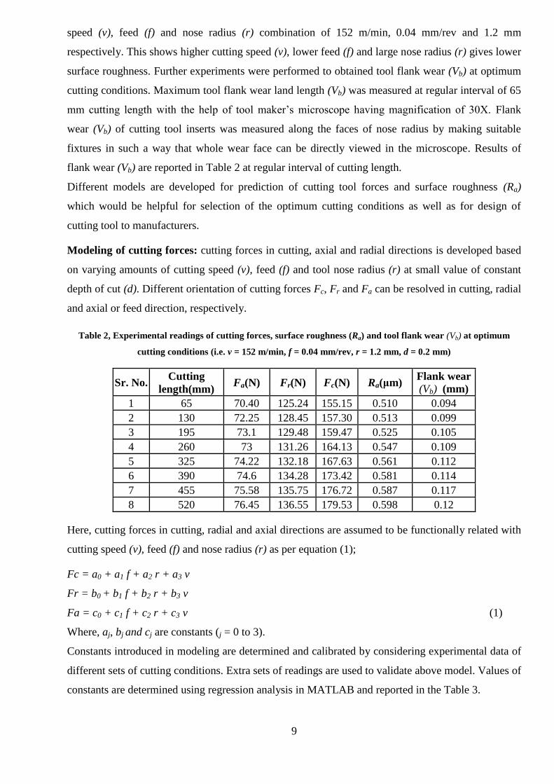
speed (v), feed (f) and nose radius (r) combination of 152 m/min, 0.04 mm/rev and 1.2 mm
respectively. This shows higher cutting speed (v), lower feed (f) and large nose radius (r) gives lower
surface roughness. Further experiments were performed to obtained tool flank wear (Vb) at optimum
cutting conditions. Maximum tool flank wear land length (Vb) was measured at regular interval of 65
mm cutting length with the help of tool maker’s microscope having magnification of 30X. Flank
wear (Vb) of cutting tool inserts was measured along the faces of nose radius by making suitable
fixtures in such a way that whole wear face can be directly viewed in the microscope. Results of
flank wear (Vb) are reported in Table 2 at regular interval of cutting length.
Different models are developed for prediction of cutting tool forces and surface roughness (Ra)
which would be helpful for selection of the optimum cutting conditions as well as for design of
cutting tool to manufacturers.
Modeling of cutting forces: cutting forces in cutting, axial and radial directions is developed based
on varying amounts of cutting speed (v), feed (f) and tool nose radius (r) at small value of constant
depth of cut (d). Different orientation of cutting forces Fc, Fr and Fa can be resolved in cutting, radial
and axial or feed direction, respectively.
Table 2, Experimental readings of cutting forces, surface roughness (Ra) and tool flank wear (Vb) at optimum
cutting conditions (i.e. v = 152 m/min, f = 0.04 mm/rev, r = 1.2 mm, d = 0.2 mm)
Sr. No. Cutting
length(mm) Fa(N) Fr(N) Fc(N) Ra(μm)
Flank wear
(Vb) (mm)
1 65 70.40 125.24 155.15 0.510 0.094
2 130 72.25 128.45 157.30 0.513 0.099
3 195 73.1 129.48 159.47 0.525 0.105
4 260 73 131.26 164.13 0.547 0.109
5 325 74.22 132.18 167.63 0.561 0.112
6 390 74.6 134.28 173.42 0.581 0.114
7 455 75.58 135.75 176.72 0.587 0.117
8 520 76.45 136.55 179.53 0.598 0.12
Here, cutting forces in cutting, radial and axial directions are assumed to be functionally related with
cutting speed (v), feed (f) and nose radius (r) as per equation (1);
Fc = a0 + a1 f + a2 r + a3 v
Fr = b0 + b1 f + b2 r + b3 v
Fa = c0 + c1 f + c2 r + c3 v (1)
Where, aj, bj and cj are constants (j = 0 to 3).
Constants introduced in modeling are determined and calibrated by considering experimental data of
different sets of cutting conditions. Extra sets of readings are used to validate above model. Values of
constants are determined using regression analysis in MATLAB and reported in the Table 3.
10
Table 3, Model constants evaluated using 27 experimental readings as per Table 1
j = 0 j = 1 j = 2 j = 3
aj 90.7448 623.2986 76.4292 -0.5014
bj 64.4884 573.8056 72.2194 -0.3831
cj 47.9123 304.4306 37.9764 -0.259
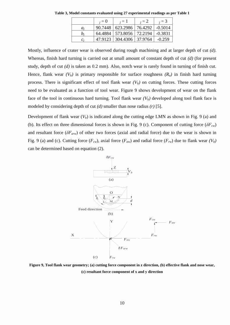
Mostly, influence of crater wear is observed during rough machining and at larger depth of cut (d).
Whereas, finish hard turning is carried out at small amount of constant depth of cut (d) (for present
study, depth of cut (d) is taken as 0.2 mm). Also, notch wear is rarely found in turning of finish cut.
Hence, flank wear (Vb) is primary responsible for surface roughness (Ra) in finish hard turning
process. There is significant effect of tool flank wear (Vb) on cutting forces. These cutting forces
need to be evaluated as a function of tool wear. Figure 9 shows development of wear on the flank
face of the tool in continuous hard turning. Tool flank wear (Vb) developed along tool flank face is
modeled by considering depth of cut (d) smaller than nose radius (r) [5].
Development of flank wear (Vb) is indicated along the cutting edge LMN as shown in Fig. 9 (a) and
(b). Its effect on three dimensional forces is shown in Fig. 9 (c). Component of cutting force (δFcw)
and resultant force (δFarw) of other two forces (axial and radial force) due to the wear is shown in
Fig. 9 (a) and (c). Cutting force (Fcw), axial force (Faw) and radial force (Frw) due to flank wear (Vb)
can be determined based on equation (2).
d
Vb
L M
N
Y
X
O
(a)
(b)
Fcw
Z
Fcw
Faw
Frw
Feed direction
Frw
Farw
Faw
(c)
Figure 9, Tool flank wear geometry; (a) cutting force component in z direction, (b) effective flank and nose wear,
(c) resultant force component of x and y direction

11
0LMN
LM MN
π/2
0 π/2 0
LM MN
= =
π= - cos + sin -
2
π= - cos + sin -
2
π= sin + cos -
2
= s
2 b
1
b 2 b
1
θ V
cw cw wθ
aw arw arw
V θ V
w wθ
rw arw arw
w
F δF r τ (z) dz dθ
F δF θ δF θ
r σ (z) θ dz dθ r σ (z) θ dz dθ
F δF θ δF θ
r σ (z)
π/2
0 π/2 0
πin + cos -
2
b 2 b
1
V θ V
wθ
θ dz dθ r σ (z) θ dz dθ
(2)
Where, -1 -1cos sin1 2θ = (f / (2r)) and θ = π - ((r - d) / r)
Based on known value of feed (f), tool nose radius (r) and depth of cut (d); θ1 and θ2 can be easily
calculated. Tool flank wear length (Vb) is measured using tool maker’s microscope at some interval
of cutting length. Shear stress and normal stress can be evaluated based on slip line field theory [5,
23]. Stresses are calculated based on shear angle (Ø) which is the function of inclination angle (i) and
normal rake angle (α) [23, 24]. So, it is easy to obtained cutting force (Fcw), radial force (Frw) and
axial force (Faw) induced due to progressive flank wear.
So, in hard turning, total force in particular direction is obtained by summation of force component
due to variable cutting condition and force component due to progressive flank wear in respective
direction. Hence, total cutting force (Fct), total axial force (Fat) and total radial force (Frt) can be
presented as;
Fct = Fc + Fcw
Fat = Fa + Faw
Frt = Fr + Frw (3)
Force model based on variable cutting conditions as presented in equation (2), is validated by
comparison of predicted values of cutting force (Fc), radial force (Fr) and axial force (Fa) with
experimental values of cutting forces for six different experiments. Table 4, 5 and 6 shows the
comparison of predicted force values with experimental force values for cutting force (Fc), radial
force (Fr) and axial force (Fa), respectively.
Table 4, Experimental validation of predicted cutting force (Fc pred)
Exp.
No. v (m/min) f (mm/rev) r (mm) Fc exp (N) Fc pred (N) % variation
1 81 0.05 0.8 137.91 142.44 -3.28
2 153 0.05 0.8 99.23 106.34 -7.16
3 117 0.06 1.2 155.15 161.19 -3.90
4 153 0.07 1.2 142.15 149.38 -5.08
5 117 0.05 0.4 91.48 93.82 -2.56
6 153 0.06 0.4 78.67 82.00 -4.23

12
Table 5, Experimental validation of predicted radial force (Fr pred)
Exp.
No. v (m/min) f (mm/rev) r (mm) Fr exp (N) Fr pred (N) % variation
1 81 0.05 0.8 113.15 119.92 -5.98
2 153 0.05 0.8 88.47 92.34 -4.37
3 117 0.06 1.2 134.53 140.76 -4.63
4 153 0.07 1.2 123.34 132.70 -7.59
5 117 0.05 0.4 72.67 77.24 -6.29
6 153 0.06 0.4 64.91 69.19 -6.59
Table 6, Experimental validation of predicted axial force (Fa pred)
Exp.
No. v (m/min) f (mm/rev) r (mm) Fa exp (N) Fa pred (N) % variation
1 81 0.05 0.8 68.67 72.54 -5.63
2 153 0.05 0.8 57.53 53.89 6.33
3 117 0.06 1.2 85.1 81.45 4.29
4 153 0.07 1.2 72.3 75.17 -3.97
5 117 0.05 0.4 45.24 48.02 -6.15
6 153 0.06 0.4 39.43 41.74 -5.86
Validation of force model considering flank wear (Vb) as per equation (3) for machining parameters
(v, f and d), tool nose radius (r) and cutting length as per Table 2 is presented in Fig. 10, 11 and 12.
Figure 10, Total cutting force (Fct) considering flank wear (Vb)
Figure 11, Total axial force (Fat) considering flank wear (Vb)
145 150 155 160 165 170 175 180 185
0.09 0.095 0.1 0.105 0.11 0.115 0.12 0.125 To
tal
cutt
ing
fo
rce
Fct
(N)
Tool flank wear (mm)
Prediction
Experimental
66
68
70
72
74
76
78
0.09 0.094 0.098 0.102 0.106 0.11 0.114 0.118 0.122
To
tal
axia
l fo
rce
Fa
t (N
)
Tool flank wear (mm)
Prediction
Experimental
13
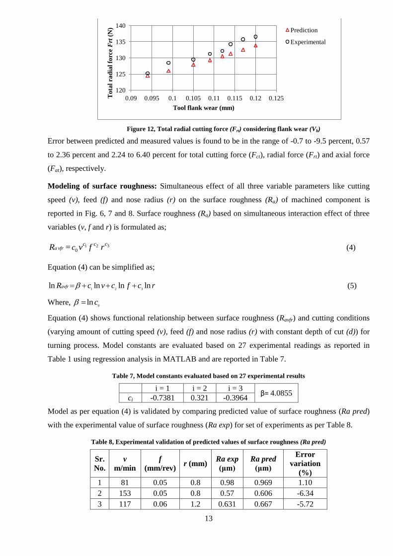
Figure 12, Total radial cutting force (Frt) considering flank wear (Vb)
Error between predicted and measured values is found to be in the range of -0.7 to -9.5 percent, 0.57
to 2.36 percent and 2.24 to 6.40 percent for total cutting force (Fct), radial force (Frt) and axial force
(Fat), respectively.
Modeling of surface roughness: Simultaneous effect of all three variable parameters like cutting
speed (v), feed (f) and nose radius (r) on the surface roughness (Ra) of machined component is
reported in Fig. 6, 7 and 8. Surface roughness (Ra) based on simultaneous interaction effect of three
variables (v, f and r) is formulated as;
31 20a vfr
cc ccR = v f r
(4)
Equation (4) can be simplified as;
1 2 3ln ln ln lnavfrR c v c f c r (5)
Where, 0
ln c
Equation (4) shows functional relationship between surface roughness (Ravfr) and cutting conditions
(varying amount of cutting speed (v), feed (f) and nose radius (r) with constant depth of cut (d)) for
turning process. Model constants are evaluated based on 27 experimental readings as reported in
Table 1 using regression analysis in MATLAB and are reported in Table 7.
Table 7, Model constants evaluated based on 27 experimental results
i = 1 i = 2 i = 3 β= 4.0855
ci -0.7381 0.321 -0.3964
Model as per equation (4) is validated by comparing predicted value of surface roughness (Ra pred)
with the experimental value of surface roughness (Ra exp) for set of experiments as per Table 8.
Table 8, Experimental validation of predicted values of surface roughness (Ra pred)
Sr.
No.
v
m/min
f
(mm/rev) r (mm)
Ra exp
(μm)
Ra pred
(μm)
Error
variation
(%)
1 81 0.05 0.8 0.98 0.969 1.10
2 153 0.05 0.8 0.57 0.606 -6.34
3 117 0.06 1.2 0.631 0.667 -5.72
120
125
130
135
140
0.09 0.095 0.1 0.105 0.11 0.115 0.12 0.125 To
tal
rad
ial
forc
e F
rt (
N)
Tool flank wear (mm)
Prediction
Experimental

14
4 153 0.07 1.2 0.541 0.575 -6.29
5 117 0.05 0.4 0.98 0.973 0.76
6 153 0.06 0.4 0.83 0.846 -1.92
G. ACHIEVEMENTS WITH RESPECT TO OBJECTIVES
Experiments are performed at different cutting conditions and tool geometries. Cutting forces (axial
(Fa), radial (Fr) and cutting force (Fc)) and surface roughness (Ra) are measured and recorded for
analysis of hard turning. Empirical models for cutting forces and surface roughness (Ra) are
developed and validated using new set of experiments. Results are analyzed to draw specific
conclusions.
Optimum cutting conditions (i.e. cutting speed (v) 152 m/min, feed (f) 0.04 mm/rev and tool nose
radius (r) 1.2 mm) are obtained based on minimum value of surface roughness (Ra) 0.504 µm.
Modeling of three dimensional tool forces is evaluated as a function of all variable factors during
turning. To enhance the accuracy of force model, cutting forces produce due to progressive flank
wear (Vb) are evaluated and added to obtain total forces (cutting forces in axial, radial and cutting
directions) produce during finish hard turning. Results predicted using empirical force model are
compared with that obtained using different set of experiments and are found to be in reasonable
agreement.
Surface roughness model is developed and validated with other sets of experiments and predicted
values of surface roughness (Ra) are found to be in close agreement with experimental results.
H. CONCLUSION
This research comprises the empirical modeling of three dimensional forces and analysis of effect of
cutting speed (v), feed (f) and nose radius (r) on cutting force (Fc), radial force (Fr) and axial force
(Fa). Also, experimental values of surface roughness (Ra) obtained based on various cutting
conditions and tool nose radius (r) are used for development of empirical model of surface roughness
(Ra) of in the hard turning of AISI D2 steel using CBN tools. From analysis and modeling of cutting
tool forces and surface roughness (Ra), following conclusions are drawn:
Cutting forces:
Cutting forces decrease with increment of cutting speed (v). Influence of variation of nose radius
(r) on tool performance is clearly observed. When tool nose radius (r) increases from 0.4 mm to
1.2 mm, cutting forces in axial, radial and cutting directions are increased. Also cutting forces
increases with increase of feed (f).
Empirical method is used to develop relationship between three dimensional cutting forces and
variable cutting conditions of hard turning. Complex oblique cutting process is evaluated as
simplified linear model which shows functional relationship of cutting force (Fc), radial force
(Fr), axial force (Fa) with variable cutting speed (v), feed (f) and tool nose radius (r) in the hard

15
turning of AISI D2 steel with CBN tools. So, it is useful to identify input variable which affects
cutting forces significantly.
Empirical model for progressive flank wear is developed to inculcate the effect of flank wear on
cutting forces. Based on the validation it was observed that, cutting forces can be predicted more
accurately by considering flank wear.
Error between predicted and measured values is found to be in the range of -0.7 to -9.5 percent,
0.57 to 2.36 percent and 2.24 to 6.40 percent for total cutting force (Fct), radial force (Frt) and
axial force (Fat), respectively. This shows effectiveness of developed empirical models for
prediction of cutting forces.
Surface roughness:
Linear and exponential empirical relationship found between the input variables (cutting speed
(v), feed (f), nose radius (r)) and surface roughness (Ra) of AISI D2 steel during hard turning.
Surface roughness (Ra) decreases with reduction in feed (f) from 0.2 mm/rev to 0.04 mm/rev;
whereas, surface roughness (Ra) decreases with increase in cutting speed (v) from 80 m/min to
152 m/min. When tool nose radius (r) increases from 0.4 mm to 1.2 mm, surface roughness (Ra)
is found to be decreasing. Lower surface roughness (Ra) (0.504 µm) of machined part is achieved
at lower feed (f), high cutting speed (v) and large nose radius (r).
Developed empirical model shows the functional relationship of feed (f), cutting speed (v), nose
radius (r) and surface roughness (Ra).
ln 4.0855 0.7381ln 0.321ln 0.3964lnavfrR v f r
Validation of developed model is performed using different sets of experiment and found to be in
reasonable agreement with experimental results of surface roughness (Ra) with error variation of
about –6.35 percent to 0.75 percent.
Overall, complete analysis of cutting forces and surface roughness (Ra) of machined AISI D2 steel
based on different cutting conditions along with tool geometries can be obtained. Also, models of
cutting forces and surface roughness (Ra) are conceptually evaluated for effective prediction of
cutting forces and surface roughness (Ra) at different cutting conditions.
I. COPIES OF PAPERS PUBLISHED AND A LIST OF ALL PUBLICATIONS ARISING
FROM THE THESIS
Sr.
No.
Title of research paper Name of Journal
1 Analysis and Prediction of Tool wear,
Machined Surface Roughness and Force
Components in Hard Turning – A Review.
2nd
National Conference on Thermal
Fluid and Manufacturing science –
2014 (TFMS -2014) (ISBN: 978-81-
927693-3-2)
16
2 Analytical and Empirical Modelling of
Wear and Forces of CBN Tool in Hard
Turning - A Review
Journal of The Institutions of
Engineers (India) – Series C
(doi:10.1007/s40032-016-0310-5)
3 Analysis and prediction of tool wear,
machined surface roughness in Hard
turning
International Journal for Scientific
Research & Development; Vol. 2,
Issue 02, 2014, ISSN: 2321-0613
4 Analysis and modeling of surface
roughness based on cutting parameters
and tool nose radius in turning of AISI D2
steel using CBN tool
Measurement (Elsevier) [Under
Review] (MEAS-D-17-00380)
5 Modeling of tool forces for turning of
hardened AISI D2 steel using cubic boron
nitride tools considering progressive flank
wear
Journal of Mechanical Science and
Technology (Springer) [Under
Review] (MEST-D-17-01356)
J. REFERENCES
[1] G. Bartarya, S. Choudhury (2012) State of the art in hard turning, International Journal of Machine Tools and
Manufacture, 53, 1-14.
[2] Y.K. Chou, C.J. Evans (1997) Tool wear mechanism in continuous cutting of hardened tool steels, Wear, 212, 59-65.
[3] D. Lalwani, N. Mehta, P. Jain (2008) Experimental investigations of cutting parameters influence on cutting forces
and surface roughness in finish hard turning of MDN250 steel, Journal of materials processing technology, 206, 167-179.
[4] A. Moufki, A. Devillez, D. Dudzinski, A. Molinari (2004) Thermomechanical modelling of oblique cutting and
experimental validation, International Journal of Machine Tools and Manufacture, 44, 971-989.
[5] Y. Huang, S.Y. Liang (2005) Modeling of cutting forces under hard turning conditions considering tool wear effect,
Transactions of the ASME-B-Journal of Manufacturing Science and Engineering, 127, 262-270.
[6] K.-M. Li, S.Y. Liang (2007) Modeling of cutting forces in near dry machining under tool wear effect, International
Journal of Machine Tools and Manufacture, 47, 1292-1301.
[7] T. Özel, Y. Karpat, L. Figueira, J.P. Davim (2007) Modelling of surface finish and tool flank wear in turning of AISI
D2 steel with ceramic wiper inserts, Journal of materials processing technology, 189, 192-198.
[8] A. Agrawal, S. Goel, W.B. Rashid, M. Price (2015) Prediction of surface roughness during hard turning of AISI 4340
steel (69 HRC), Applied Soft Computing, 30, 279-286.
[9] I. Asiltürk, M. Çunkaş (2011) Modeling and prediction of surface roughness in turning operations using artificial
neural network and multiple regression method, Expert Systems with Applications, 38, 5826-5832.
[10] D. Singh, P.V. Rao (2007) A surface roughness prediction model for hard turning process, The International Journal
of Advanced Manufacturing Technology, 32, 1115-1124.
[11] H. Aouici, M.A. Yallese, K. Chaoui, T. Mabrouki, J.-F. Rigal (2012) Analysis of surface roughness and cutting
force components in hard turning with CBN tool: Prediction model and cutting conditions optimization, Measurement,
45, 344-353.
[12] S. Thamizhmanii, S. Saparudin, S. Hasan (2007) Analyses of surface roughness by turning process using Taguchi
method, Journal of Achievements in Materials and Manufacturing Engineering, 20, 503-506.
[13] M. Mehrban, D. Naderi, V. Panahizadeh, H.M. Naeini (2008) Modelling of tool life in turning process using
experimental method, International journal of material forming, 1, 559-562.

17
[14] R. Suresh, S. Basavarajappa, G. Samuel (2012) Some studies on hard turning of AISI 4340 steel using multilayer
coated carbide tool, Measurement, 45, 1872-1884.
[15] J. Lima, R. Avila, A. Abrao, M. Faustino, J.P. Davim (2005) Hard turning: AISI 4340 high strength low alloy steel
and AISI D2 cold work tool steel, Journal of Materials Processing Technology, 169, 388-395.
[16] J.P. Davim, L. Figueira (2007) Machinability evaluation in hard turning of cold work tool steel (D2) with ceramic
tools using statistical techniques, Materials & design, 28, 1186-1191.
[17] G. Poulachon, B. Bandyopadhyay, I. Jawahir, S. Pheulpin, E. Seguin (2004) Wear behavior of CBN tools while
turning various hardened steels, Wear, 256, 302-310.
[18] L. Tang, C. Gao, J. Huang, X. Lin, J. Zhang (2014) Experimental investigation of the three-component forces in
finish dry hard turning of hardened tool steel at different hardness levels, The International Journal of Advanced
Manufacturing Technology, 70, 1721-1729.
[19] M. Liu, J.-i. Takagi, A. Tsukuda (2004) Effect of tool nose radius and tool wear on residual stress distribution in
hard turning of bearing steel, Journal of Materials Processing Technology, 150, 234-241.
[20] C.-S. Chang (1998) A force model for nose radius worn tools with a chamfered main cutting edge, International
Journal of Machine Tools and Manufacture, 38, 1467-1498.
[21] K. Bouacha, M.A. Yallese, S. Khamel, S. Belhadi (2014) Analysis and optimization of hard turning operation using
cubic boron nitride tool, International Journal of Refractory Metals and Hard Materials, 45, 160-178.
[22] G. Bartarya, S. Choudhury (2012) Effect of cutting parameters on cutting force and surface roughness during finish
hard turning AISI52100 grade steel, Procedia CIrP, 1, 651-656.
[23] D.J. Waldorf, R.E. DeVor, S.G. Kapoor (1998) A slip-line field for ploughing during orthogonal cutting,
Transactions-American Society Of Mechanical Engineers Journal Of Manufacturing Science And Engineering, 120, 693-
699.
[24] G. Lal (1996) Introduction to machining science, New Age International.