investigation of fcc position impacts on hadron injectors john osborne, charlie cook, yung loo...
TRANSCRIPT

Investigation of FCC positionImpacts on Hadron Injectors
John Osborne, Charlie Cook, Yung Loo (ARUP)16/09/2014
2
Contents• Preliminary findings: Investigation of FCC Hadron Injector (FHI)
& geo/tunnelling impacts for 83km/100km ring siting
• Geology/CE Studies Progress Flow
• 100km- Circle and Racetrack – optimised alignment options within
study area limits
• 83km- Circle and Racetrack – optimised alignment options within
study area limits
• Alternatives and FHI constraints

Geology - Definition of key variables and investigation boundaries
- Terrain, overburden- Broad Ground Conditions which have
engineering impact (Moraine, Molasse, Cretaceous, Faults)
- Hydrology (Lake, Rivers)
Preliminary Machine Requirements
- Tunnel Length- Tunnel Shape- Tunnel Depth- Tunnel Slope- Location of Experimental Halls/Access Shafts
• Updated aims and requirements• e.g. laser straight,
corrections for ellipsoid• Updates on data constraints• Key decision output choices• GIS Useability / Accessability /
Transfer of Knowledge
BIM
TO
OL
DE
CIS
ION
AID
• BRGM Cretaceous Seismics
• Bathymetry data• Tool functionality
• CE constructability • Tunnelling, Geotechnics, Programme
• Interfaces Requirements• FHI requirements• Experimental groups• Iterations of constraints/requirements
assessment of a most feasible solution• Performance Design Requirements / Design Basis
(offline data manipulation)• Excel• GIS
INIT
IAL
PR
OJE
CT
V
AR
IAB
LE
S &
AS
SU
MP
TIO
NS
ITE
RA
TIO
NS
BIM tool export Model UpdatesAssessments & Studies
FCC - Geology/CE Studies Progress Flow

4
100km Circle: Study Boundary Limits - North
• To minimise connection distance of injection tunnel between LHC and FCC, beneficial to locate
ring further east but constrained by Chablais
• Potential alignment optimisation with tilt, but unlike with LHC slope (solely to reduce Jura
impact). FCC - A beneficial tilt in one direction would be a negative tilt in another:
- i.e. three main mtns, Jura, Saleve, Pre Alps Chablais (+Le Vuache)
- Any tilt is also constrained by The Rhone
FHI Impacts Geo/Tunnelling Impacts
Positives • Possibility of good near parallel injection tunnel length into LHC P3, P4, P5.
Negatives • 10km spacing of detector caverns/shafts not possible due to alignment spacing between Pre Alpes du Chablais crossing (1km deep shaft) and lake
• Lake bed deeper• Top of molasse deeper• NE of ring moves out of
Valee de L’Arve corridor into Chablais

5
100km Circle: Study Boundary Limits - North- General Scenario of Crossing near P3-P5
Riverbed
Molasse Rockhead
370
mASL
280
150*
Azimuth SlopemASL at
LakeAv. mASL Rationale
mASL near crossover
P3-5, mASLP3-5/FCC distance
Scenario 1a 0 0 150 150 top of molasse under lake 150
Scenario 1b 0 0 280 280 Bottom of riverbed 280
Scenario 2 0 0.5 150 273top of molasse under lake, bottom of
the Rhone145 - 180
Scenario 3 95 0.4 150 193top of molasse under lake, bottom of the Rhone, tunnel depth low under
Jura145 - 180
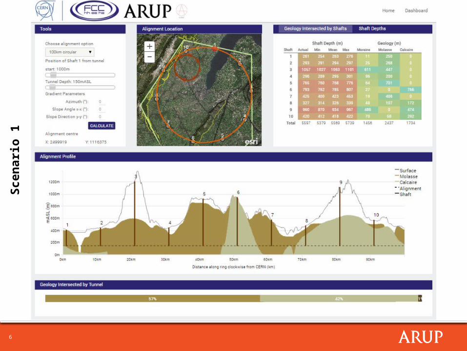
6
Scen
ario
1

7
Scen
ario
2

8
Scen
ario
3

9
100km Racetrack: Study Boundary Limits - North• Same issues as 100km Circle. In addition:
- Northern Limit is constrained by southern extent of racetrack crossing into
Grand Saleve (no benefit of crossing further north into Saleve)
- At NW extent of investigation area , Jura outcrops back towards Lake. Need
to move ring further east into Pre Alpes du Chablais to avoid this.
- Western edge continuously skirts Jura – high interface risk. Likewise,
pushing ring further east enters Chablais.
• However potential advantageous straight parallel alignment into P3,P4

10
100km Circle: Study Boundary Limits - South
• Savings in tilt but constrained by the Rhone and Les Usses
FHI Impacts Geo/Tunnelling
Positives • Ring will pass under LHC, with potential good connection for injection tunnel (FCC passes near perpendicular to Point 1(and P7)).
• Lake bed shallower• Top of molasse shallower• Completely avoids Jura*• Avoids Pre-Alpes du Chablais+
Negatives • *(enters Le Vuache)• +(lies in the foothills not Valee de L’Arve
corridor between Saleve and Pre Alpes)• Starts to skirt Bornes-Aravais mtns to SE
(current uncertainty in geological data) • Molasse tapers out as situated towards
extreme southern tip of basin – Ground becomes more heterogeneous and faulted, more uncertainty and risk for tunnelling and shaft sinking.

11
100km Circle: Study Boundary Limits - South- General Scenario of Crossing near P1
Riverbed
Molasse Rockhead
370
mASL
320
210
Azimuth SlopemASL at
LakeAv. mASL Rationale
mASL near crossover
P1, mASLP1/FCC distance
Scenario 1a 0 0 210 210 top of molasse under lake 210 359 149m
Scenario 1b 0 0 320 320 Bottom of riverbed 320 359 39m
Scenario 2 0 0.23 210 290
top of molasse under lake,bottom of the Rhone, les ussesTilted into southern mountains
(Vuache, Bornes, Saleve)
215 359 144m

12
Scen
ario
1

13
Scen
ario
2

14
100km Racetrack: Study Boundary Limits - South
A B
A
B
• Limited capacity for movement. • Bound strictly by Jura, Vuache, Bornes• Poor connection at Point 1, esp. option B

15
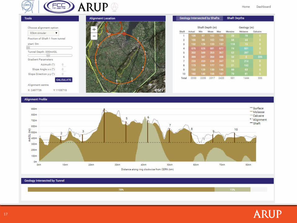
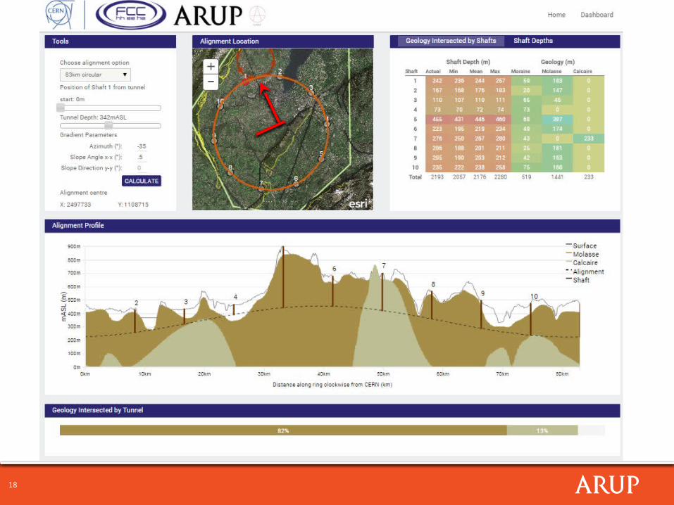
83km Circular- General Scenario of Crossing at P1
Riverbed
Molasse Rockhead
370
mASL
340
210
Azimuth SlopemASL at
LakeAv. mASL Rationale
mASL near crossover
P1, mASLP1/FCC distance
Scenario 1a 0 0 270 270 top of molasse under lake 270 359 89m
Scenario 1b 0 0 330 330Non-inclined, Bottom of riverbed,
bottom of the Rhone330 359 29m
Scenario 2 -035 0.5 210 342
Sloping high point in Borne/Saleve. Limited by Les Usses. Goes through
moraine @Valee de l’Arve (connectivity of flow not as
influential as under lake)
230 359 129m

16
83km Circular- General Scenario of Crossing at P1
• Circular – Current default plan position near optimum
• Well positioned directly beneath and inline with P1
• Positioned well at shallower southern end of lake
• Well positioned east away from Jura
17
18
19
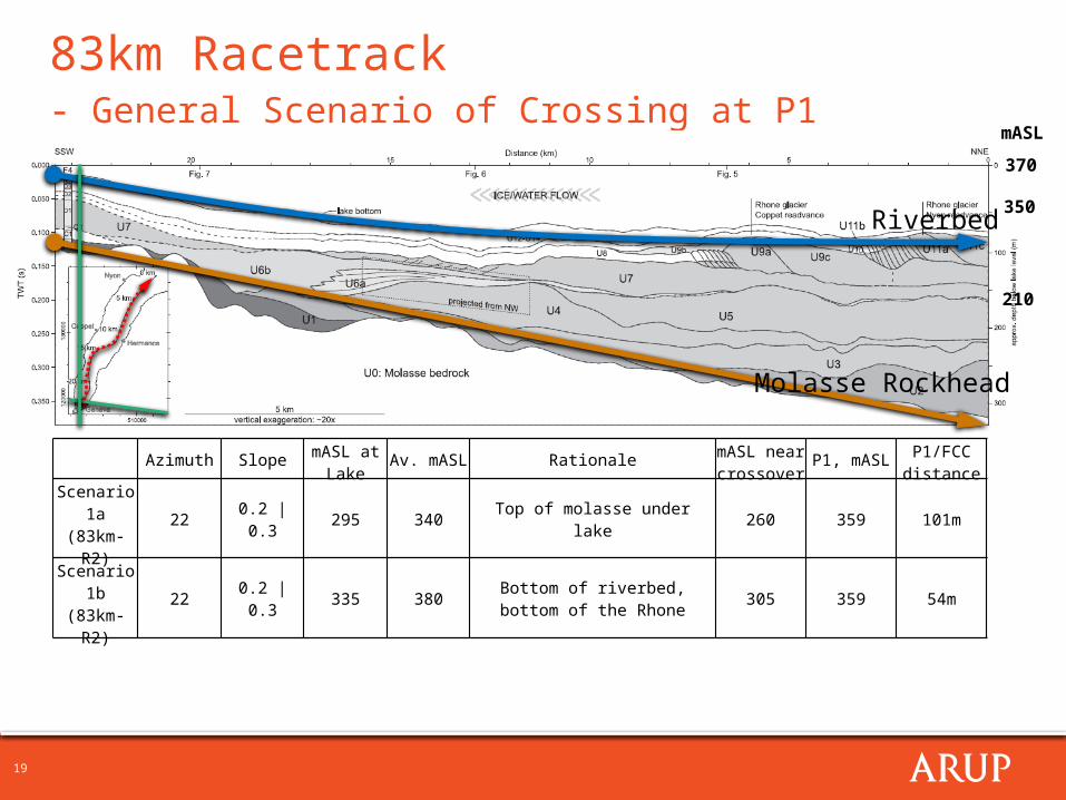
83km Racetrack- General Scenario of Crossing at P1
Riverbed
Molasse Rockhead
370
mASL
350
210
Azimuth SlopemASL at
LakeAv. mASL Rationale
mASL near crossover
P1, mASLP1/FCC distance
Scenario 1a(83km-R2)
22 0.2 | 0.3 295 340 Top of molasse under lake 260 359 101m
Scenario 1b(83km-R2)
22 0.2 | 0.3 335 380Bottom of riverbed, bottom of the
Rhone305 359 54m

20
Scen
ario
1

21
Scen
ario
2

22
FCC-LHC Hadron Injection Constraints (1)
- “Required injection straight length is a function of the vertical height difference between LHC and FCC at P1 and the magnet technology”
- “For 20 – 200 m height difference and reasonable magnet technologies get about 0.5 to 1.5 km injection straight length per beam”
• To achieve these tolerances:
• Possible with 100km option but higher engineering risk
• More feasible to achieve shallow (50-100m) height differences and shorter injection straight lengths with 83km option.
• Both racetrack and circular options can be preferentially tilted and orientated to achieve much more satisfactory crossover relationships.
• Need to consider non-molasse boring options
• Can be better constrained through understanding dipole designs/injection approach limits
23
FCC-LHC Hadron Injection Constraints (2)
- First Version of the Geology Tool should be imported onto CERN database this week
- Working meeting with CE and Hadron experts to be arranged for coming weeks to study options in more detail. Who should be invited ?