investigation of manufacturing residual stresses in cold ... 5/ac04405162169.pdf · in the making...
TRANSCRIPT
Dr. Chinnaraj K. et al. Int. Journal of Engineering Research and Applications www.ijera.com
ISSN : 2248-9622, Vol. 4, Issue 4( Version 5), April 2014, pp.162-169
www.ijera.com 162 | P a g e
Investigation of Manufacturing Residual Stresses in Cold Formed
Truck Frame Rail Sections
Dr. Chinnaraj K. *, Dr. Sathya Prasad M. **, Prof. Lakshmana Rao C.***
and Nantha Kumar M.* *(Product Development – Technical Centre, Ashok Leyland, Chennai, India)
** (Advanced Engineering – Technical Centre, Ashok Leyland, Chennai, India)
****(Department of Applied Mechanics, Indian Institute of Technology Madras , Chennai, India)
ABSTRACT Series of manufacturing processes such as coiling-uncoiling, cold forming and hole cutting processes involved
in the making of truck frame rail sections leave certain amount of manufacturing imperfections into the frame
rail. As the manufacturing imperfections in the form of residual stresses play a significant role in determining
the dynamic structural behavior of truck frame rail members, a careful assessment of residual stresses resulting
from coiling-uncoiling and cold forming processes is needed. In the present investigation, non-linear Finite
Element (FE) simulation of coiling-uncoiling and cold forming processes were carried out and the resulting
residual stresses in frame rail corner, flat web and flange sections were compared with the experimentally
measured residual stress values using X-ray diffraction technique. It is observed that in corner sections, the
numerically predicted residual stresses are in close agreement with the experimentally measured residual
stresses in forming (transverse) direction. In the direction perpendicular to forming (longitudinal direction),
while the trends of numerical and experimental residual stresses are observed to follow the same pattern, some
deviation in stress values are observed in the inner half of the corner sections. As the coiling-uncoiling process
is the main cause for the residual stress presence in flat web and flange sections, the computed coiling-uncoiling
residual stresses in longitudinal directions are compared with experimentally measured residual stresses in frame
web sections and the trends are observed to be in good agreement. Whereas the magnitudes of coiling-uncoiling
residual stresses in transverse direction are found to be very low and considered to be insignificant for the
comparative analysis. These residual stresses along with corresponding equivalent plastic strains and virgin
material properties in terms of stress-strain relationships can be considered as initial conditions for the accurate
prediction of truck frame rail fatigue behavior.
Keywords - coiling-uncoiling, cold forming, plastic strain, residual Stress, Truck frame rail, x-ray diffraction.
I. INTRODUCTION
The increasing demand for improved vehicle
performance and fuel efficiency have forced
commercial vehicle manufacturers to look into finer
design aspects in order to reduce vehicle weight and
at the same time improve the life of vehicle systems.
While the availability of high speed computing
hardware and finite element) simulation tools support
the designers with all virtual test simulations being
carried out in the early design stage, they often ignore
the effect of manufacturing process induced
variations and tend to use only the virgin material
properties in their numerical models to predict the
mechanical behavior of vehicle structures such as
frame rails.
The use of virgin material properties in numerical
simulations would not replicate the actual structural
behavior of frame rail sections. Normally, the frame
rails are subjected to number of manufacturing
processes such as coiling-uncoiling, cold forming and
hole cutting processes before attaining its final shape,
which invariably modify the frame rail material
properties and its mechanical behaviour. Since all
these manufacturing processes leave some amount of
residual stresses in frame rail sections due to
excessive cold working, based on its magnitude and
direction they have serious influence on its overall
structural behavior. In order to consider these
residual stresses and modified material properties as
initial conditions for further numerical analysis, a
thorough understanding of all the processes is
needed.
Although there were no specific literatures
available pertaining to the assessment of residual
stresses in automotive frame rail structures, some
experimental studies were found on cold formed steel
sections employed in general steel structural
applications. Quach [1] and Moen et al. [2] have
attempted to quantify the residual stresses resulting
from coiling-uncoiling process in cold formed carbon
RESEARCH ARTICLE OPEN ACCESS
Dr. Chinnaraj K. et al. Int. Journal of Engineering Research and Applications www.ijera.com
ISSN : 2248-9622, Vol. 4, Issue 4( Version 5), April 2014, pp.162-169
www.ijera.com 163 | P a g e
steel sections through finite element and analytical
models. While Weng and White [3, 4] have measured
surface residual stresses and through thickness
residual stresses on thick cold bent steel plates using
sectional method. It was reported that through
thickness residual stress distribution was zigzag type
and the maximum residual stress either occurs at
inside surface of the bend or near the neutral surface
of the plate.
Longitudinal residual stresses in press-braked and
roll formed carbon steel channel sections were
measured using strip-sectioning method by Batista
and Rodrigues [5]. Similar approach was used to
measure residual stresses in longitudinal direction of
cold formed carbon steel sections by Weng and
Peckoz [6] and in stainless steel square hollow
sections by Young & Lui [7]. Key and Hancock [8]
have showed complex variation of through thickness
residual stress measured in thick cold rolled square
hollow sections. A recent experimental work
concerning X-ray diffraction measurements on square
hollow sections were published by Li et al [9]
showing variation of through-thickness residual
stresses as bi-linear in both transverse and
longitudinal directions. Yet, the experimental
methods are not the only possibility of residual stress
determination, there are analytical and numerical
models [10, 11] conveniently used to predict the
residual stress distribution in cold formed sections.
All these studies found in literature gave focus on
static steel column structures and the effect of
manufacturing processes on their column buckling
behavior. There were no specific literatures found in
the area of truck frame rail structures, which
considers the effect of manufacturing processes on
the dynamic fatigue behavior of frame rails. Through
this work, an attempt was made to investigate the
residual stresses and the associated plastic strains
resulting from coiling-uncoiling and press forming
processes through numerical simulations and
compared the numerically predicted residual stresses
with the experimentally measured residual stresses in
truck frame rail sections.
1.1 Frame Material Properties The frame rail material chosen for this study is
BSK46, a widely used micro alloyed carbon steel in
truck frame rails with chemical composition of C -
1.4%, Mn - 0.03%, Nb - 0.05%, P - 0.03%, S - 0.1%
and Si - 0.03%. The mechanical properties of BSK46
material in terms of nominal stress-strain curve that
gives Young’s modulus of the material E - 210
GPa and Yield strength σy - 460 MPa is as shown in
Fig. 1.
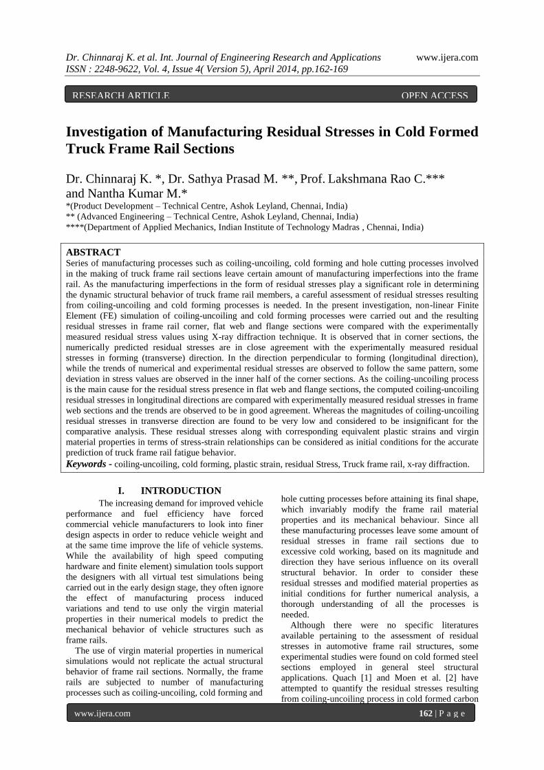
Fig.1. BSK46 material properties
The Poisson ratio measured is ν - 0.29. As the
material non-linearity requires true stress-logarithmic
plastic strain curve, it was derived from nominal
stress-strain data up to the ultimate point and input
data points were generated for numerical analysis.
1.2 Frame Section Dimensions Fig. 2 depicts the sectional dimensions of frame
rail sections chosen for numerical and experimental
investigations in this work.
Fig. 2. Frame section dimensions
The dimensions w, f and t denote web height,
flange width and thickness of frame rail sections
respectively. While D is diameter of coil at which the
steel sheet is extracted for frame rail section and r is
inner radius of corner section.
II. COILING-UNCOILING SIMULATION The steel sheets are normally transported as
compact coils from steel mills to frame rail
manufacturers. The coils received at frame rail
manufacturing locations are first uncoiled and then
subjected to cold forming process to attain final
shape of the frame rail sections. These steel sheets
prior to coiling in steel mill is normally subjected to
annealing process, hence the residual stress state in
steel sheet before the cold forming processes is
mainly due to the coiling-uncoiling process the sheet
undergoes. In order to capture these residual stresses
and associated equivalent plastic strains, the coiling-
uncoiling process is simulated in Finite Element (FE)
environment. The input data points from non-linear
strain hardened material properties of BSK46 steel
grade considered for the FE simulation is shown in
Fig. 1. In order to capture the non-linear through
Dr. Chinnaraj K. et al. Int. Journal of Engineering Research and Applications www.ijera.com
ISSN : 2248-9622, Vol. 4, Issue 4( Version 5), April 2014, pp.162-169
www.ijera.com 164 | P a g e
thickness residual stresses more accurately in BSK46
grade steel sheets of 6 mm thickness, a minimum of
16 layers CPE4R elements (which are 2D plane strain
4 noded elements with reduced integration and hour
glass control for controlling deformation of elements
during sudden loading) were chosen through the
thickness and the final mesh size is arrived. Also for
capturing the exact coil diameter, analytical rigid
surface of equivalent diameter is modeled and surface
contact pairs available in ABAQUS [12] are used to
define contact between the sheet blank and the
analytical rigid surface during the first step of coiling
simulation. In this step, one end of the steel strip is
fixed and the other end of the steel blank is pulled
towards the analytical rigid surface with required
displacement load in such a way that the steel blank
takes the shape of analytical rigid surface,
representing the actual coil diameter.
In the second step, the uncoiling process is
simulated by reverse bending of steel blank to the
initial zero curvature with required displacement load
defined in the opposite direction. During the
uncoiling process, the surface contact defined in the
previous step is deactivated in order to simulate the
uncoiling process more closely. At the end, a spring
back analysis is performed in order to capture the
presence of any residual curvature as the steel blank
coming out from uncoiling machine is free from all
the constraints imposed earlier. The simulation
sequence captured during coiling-uncoiling process is
depicted pictorially in Fig. 3.
Fig. 3 Sequence of FE simulation steps in coiling-uncoiling
process
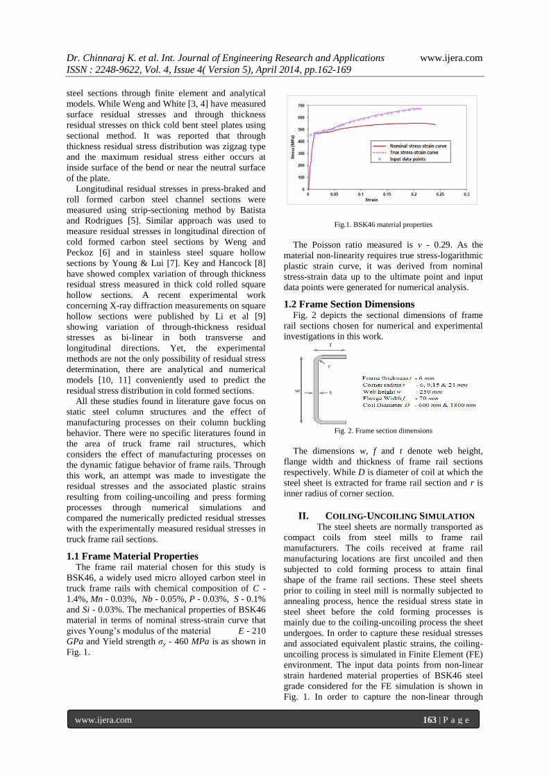
The through-thickness residual stresses in
longitudinal and transverse directions of frame rail
web and flange sections obtained through FE
simulation from various coil diameter locations due
to coiling-uncoiling processes (as they are unaffected
by cold forming process) are shown in Fig. 4 and 5. It
is very important to note that as a manufacturing
practice, the inner surface of steel coil becomes the
outer surface of frame rail section and the outer
surface of steel coil becomes the inner surface of
frame rail sections during the making of frame rail
sections.
Fig. 4 Longitudinal through-thickness residual stresses in flat web
sections derived from various coil diameter locations
Fig. 5 Transverse through-thickness residual stresses in flat web sections derived from various coil diameter locations
From the figures, it is observed that the coiling-
uncoiling residual stresses in longitudinal directions
are predominant in frame web and flange sections
and it increases with decrease in coil diameter.
Among the stress values observed through the
thickness, the outer surface longitudinal tensile
residual stress plays a significant role in deciding
dynamic fatigue cracking behavior of truck frame rail
web and flange sections, subjected to extreme road
operating conditions.
Fig. 6 Through-thickness equivalent plastic strains in flat web
sections derived from various coil diameter locations
Similarly, through-thickness equivalent plastic
strains due to coiling-uncoiling process on frame rail
flat web sections derived from various coil diameter
locations were calculated using FE simulation and
depicted in Fig. 6. From the figure, it is observed
that there are no plastic strains in the elastic core
area. As the coil diameter increases, the elastic core
thickness also increases with subsequent reduction in
plastic strain.
Dr. Chinnaraj K. et al. Int. Journal of Engineering Research and Applications www.ijera.com
ISSN : 2248-9622, Vol. 4, Issue 4( Version 5), April 2014, pp.162-169
www.ijera.com 165 | P a g e
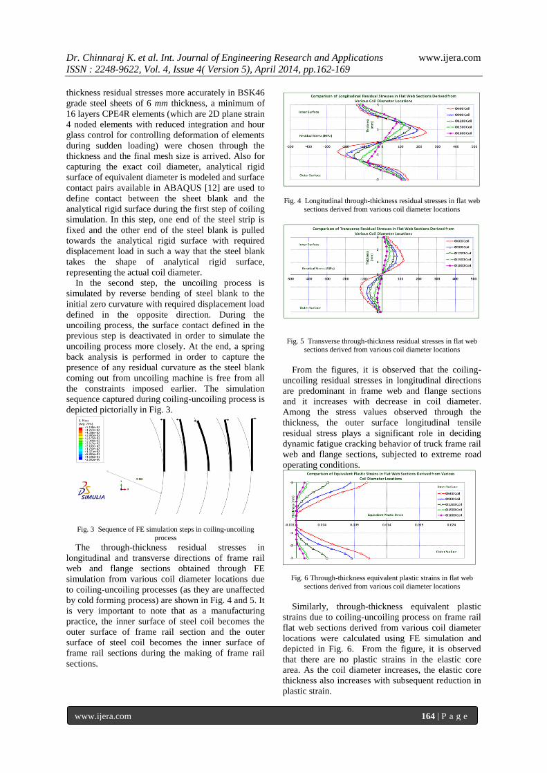
III. PRESS FORMING SIMULATION Among the three cold forming processes
such as roll forming, angle braking and press forming
process employed for making truck frame rail
sections, the press forming process that helps to
obtain final desired shape in a single pressing process
is considered for the simulation study in this work.
The sequence of steps involved in a typical press
forming simulation is described pictorially in Fig. 7.
In the finite element model, the analytical surfaces of
punch, die and blank support were modeled by
capturing the required outer section dimensions
physically. The steel blank of 6 mm thick was
modeled with 2-D plane strain 4 noded CPE4R
element as it can handle both large strains and
rotations. The interaction between punch & steel
blank, die & steel blank and support & steel blank
were modeled with surface contact pairs available in
ABAQUS.
Fig. 7. Truck frame rail press forming process steps
Both geometrical and material non-linearities were
considered in the numerical analysis. In order to
replicate the physical loading conditions in the
forming simulation, the die maintained in a fixed
position and the tool along with support are moved
(with a support load of 40 kN acting in direction
opposite to tool motion) to required forming depth
during the press forming process. Modeling of steel
blank with 16 layers of CPE4R elements through the
thickness helps to capture the varying through-
thickness residual stresses very accurately. FE
simulation was carried out for various frame sections
with corner radius to thickness (r/t) ratios of 1, 1.5,
2.5 and 3.5 by changing tool and die section
dimensions in FE models.
Fig. 8. Typical transverse residual stress contour plot in corner
section with (r/t) ratio - 3.5
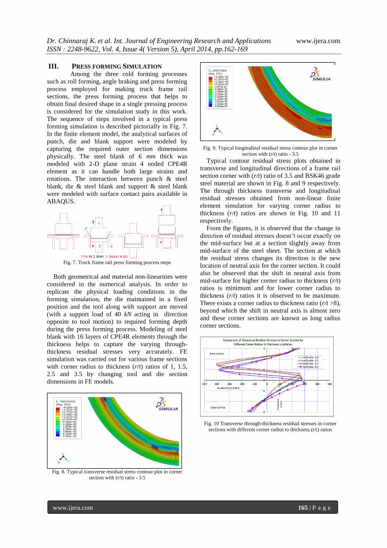
Fig. 9. Typical longitudinal residual stress contour plot in corner
section with (r/t) ratio - 3.5
Typical contour residual stress plots obtained in
transverse and longitudinal directions of a frame rail
section corner with (r/t) ratio of 3.5 and BSK46 grade
steel material are shown in Fig. 8 and 9 respectively.
The through thickness transverse and longitudinal
residual stresses obtained from non-linear finite
element simulation for varying corner radius to
thickness (r/t) ratios are shown in Fig. 10 and 11
respectively.
From the figures, it is observed that the change in
direction of residual stresses doesn’t occur exactly on
the mid-surface but at a section slightly away from
mid-surface of the steel sheet. The section at which
the residual stress changes its direction is the new
location of neutral axis for the corner section. It could
also be observed that the shift in neutral axis from
mid-surface for higher corner radius to thickness (r/t)
ratios is minimum and for lower corner radius to
thickness (r/t) ratios it is observed to be maximum.
There exists a corner radius to thickness ratio (r/t >8),
beyond which the shift in neutral axis is almost zero
and these corner sections are known as long radius
corner sections.
Fig. 10 Transverse through-thickness residual stresses in corner
sections with different corner radius to thickness (r/t) ratios
Dr. Chinnaraj K. et al. Int. Journal of Engineering Research and Applications www.ijera.com
ISSN : 2248-9622, Vol. 4, Issue 4( Version 5), April 2014, pp.162-169
www.ijera.com 166 | P a g e
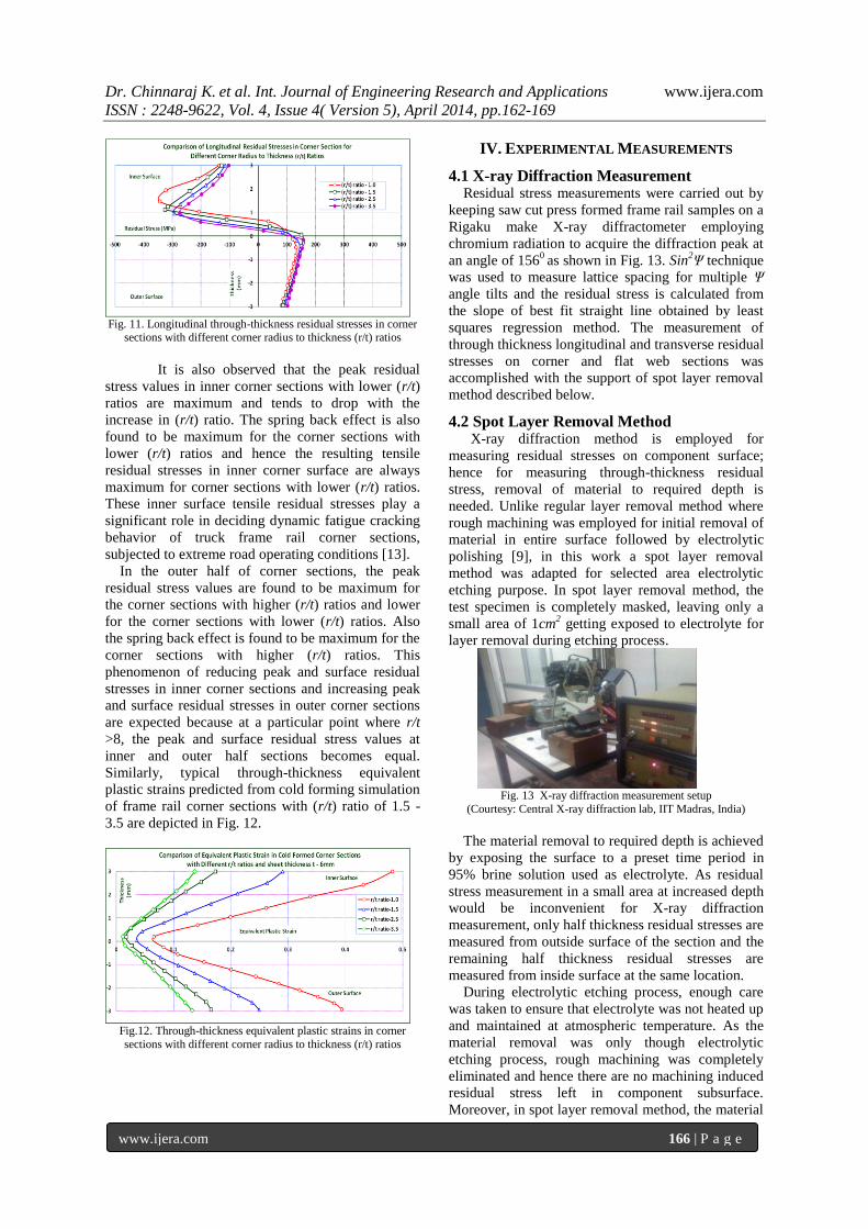
Fig. 11. Longitudinal through-thickness residual stresses in corner
sections with different corner radius to thickness (r/t) ratios
It is also observed that the peak residual
stress values in inner corner sections with lower (r/t)
ratios are maximum and tends to drop with the
increase in (r/t) ratio. The spring back effect is also
found to be maximum for the corner sections with
lower (r/t) ratios and hence the resulting tensile
residual stresses in inner corner surface are always
maximum for corner sections with lower (r/t) ratios.
These inner surface tensile residual stresses play a
significant role in deciding dynamic fatigue cracking
behavior of truck frame rail corner sections,
subjected to extreme road operating conditions [13].
In the outer half of corner sections, the peak
residual stress values are found to be maximum for
the corner sections with higher (r/t) ratios and lower
for the corner sections with lower (r/t) ratios. Also
the spring back effect is found to be maximum for the
corner sections with higher (r/t) ratios. This
phenomenon of reducing peak and surface residual
stresses in inner corner sections and increasing peak
and surface residual stresses in outer corner sections
are expected because at a particular point where r/t
>8, the peak and surface residual stress values at
inner and outer half sections becomes equal.
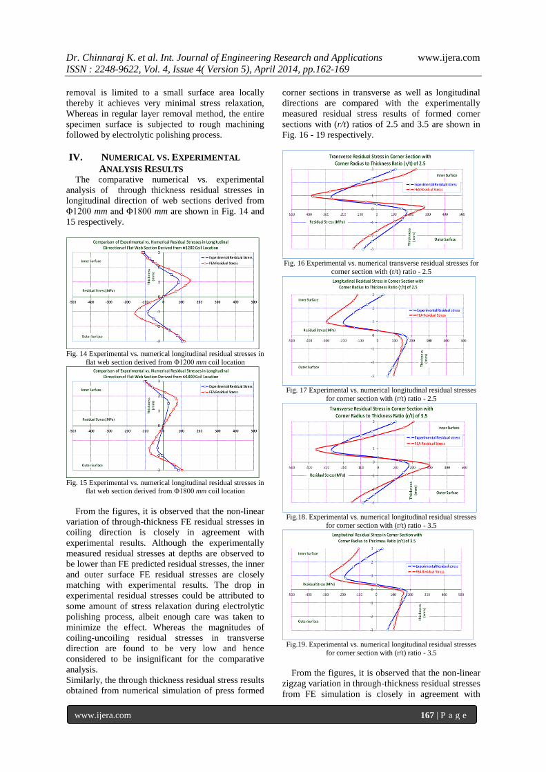
Similarly, typical through-thickness equivalent
plastic strains predicted from cold forming simulation
of frame rail corner sections with (r/t) ratio of 1.5 -
3.5 are depicted in Fig. 12.
Fig.12. Through-thickness equivalent plastic strains in corner
sections with different corner radius to thickness (r/t) ratios
IV. EXPERIMENTAL MEASUREMENTS
4.1 X-ray Diffraction Measurement Residual stress measurements were carried out by
keeping saw cut press formed frame rail samples on a
Rigaku make X-ray diffractometer employing
chromium radiation to acquire the diffraction peak at
an angle of 1560
as shown in Fig. 13. Sin2Ψ technique
was used to measure lattice spacing for multiple Ψ
angle tilts and the residual stress is calculated from
the slope of best fit straight line obtained by least
squares regression method. The measurement of
through thickness longitudinal and transverse residual
stresses on corner and flat web sections was
accomplished with the support of spot layer removal
method described below.
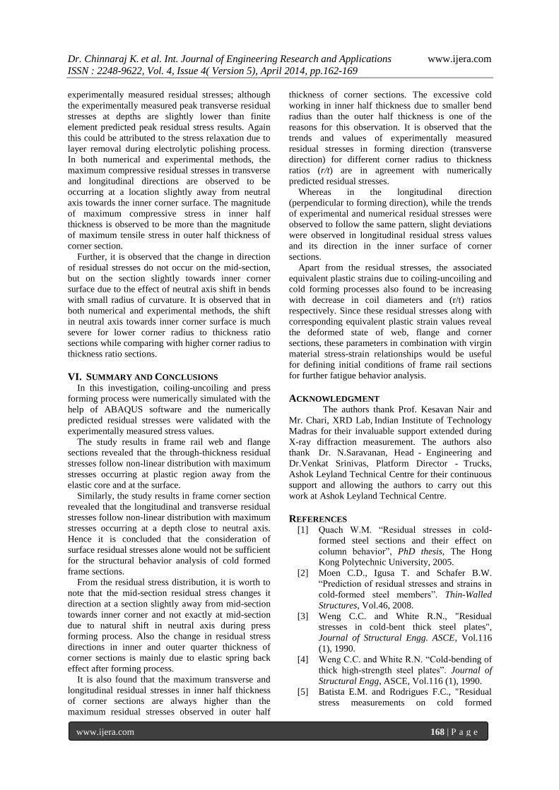
4.2 Spot Layer Removal Method
X-ray diffraction method is employed for
measuring residual stresses on component surface;
hence for measuring through-thickness residual
stress, removal of material to required depth is
needed. Unlike regular layer removal method where
rough machining was employed for initial removal of
material in entire surface followed by electrolytic
polishing [9], in this work a spot layer removal
method was adapted for selected area electrolytic
etching purpose. In spot layer removal method, the
test specimen is completely masked, leaving only a
small area of 1cm2 getting exposed to electrolyte for
layer removal during etching process.
Fig. 13 X-ray diffraction measurement setup
(Courtesy: Central X-ray diffraction lab, IIT Madras, India)
The material removal to required depth is achieved
by exposing the surface to a preset time period in
95% brine solution used as electrolyte. As residual
stress measurement in a small area at increased depth
would be inconvenient for X-ray diffraction
measurement, only half thickness residual stresses are
measured from outside surface of the section and the
remaining half thickness residual stresses are
measured from inside surface at the same location.
During electrolytic etching process, enough care
was taken to ensure that electrolyte was not heated up
and maintained at atmospheric temperature. As the
material removal was only though electrolytic
etching process, rough machining was completely
eliminated and hence there are no machining induced
residual stress left in component subsurface.
Moreover, in spot layer removal method, the material
Dr. Chinnaraj K. et al. Int. Journal of Engineering Research and Applications www.ijera.com
ISSN : 2248-9622, Vol. 4, Issue 4( Version 5), April 2014, pp.162-169
www.ijera.com 167 | P a g e
removal is limited to a small surface area locally
thereby it achieves very minimal stress relaxation,
Whereas in regular layer removal method, the entire
specimen surface is subjected to rough machining
followed by electrolytic polishing process.
IV. NUMERICAL VS. EXPERIMENTAL
ANALYSIS RESULTS The comparative numerical vs. experimental
analysis of through thickness residual stresses in
longitudinal direction of web sections derived from
Φ1200 mm and Φ1800 mm are shown in Fig. 14 and
15 respectively.
Fig. 14 Experimental vs. numerical longitudinal residual stresses in
flat web section derived from Φ1200 mm coil location
Fig. 15 Experimental vs. numerical longitudinal residual stresses in
flat web section derived from Φ1800 mm coil location
From the figures, it is observed that the non-linear
variation of through-thickness FE residual stresses in
coiling direction is closely in agreement with
experimental results. Although the experimentally
measured residual stresses at depths are observed to
be lower than FE predicted residual stresses, the inner
and outer surface FE residual stresses are closely
matching with experimental results. The drop in
experimental residual stresses could be attributed to
some amount of stress relaxation during electrolytic
polishing process, albeit enough care was taken to
minimize the effect. Whereas the magnitudes of
coiling-uncoiling residual stresses in transverse
direction are found to be very low and hence
considered to be insignificant for the comparative
analysis.
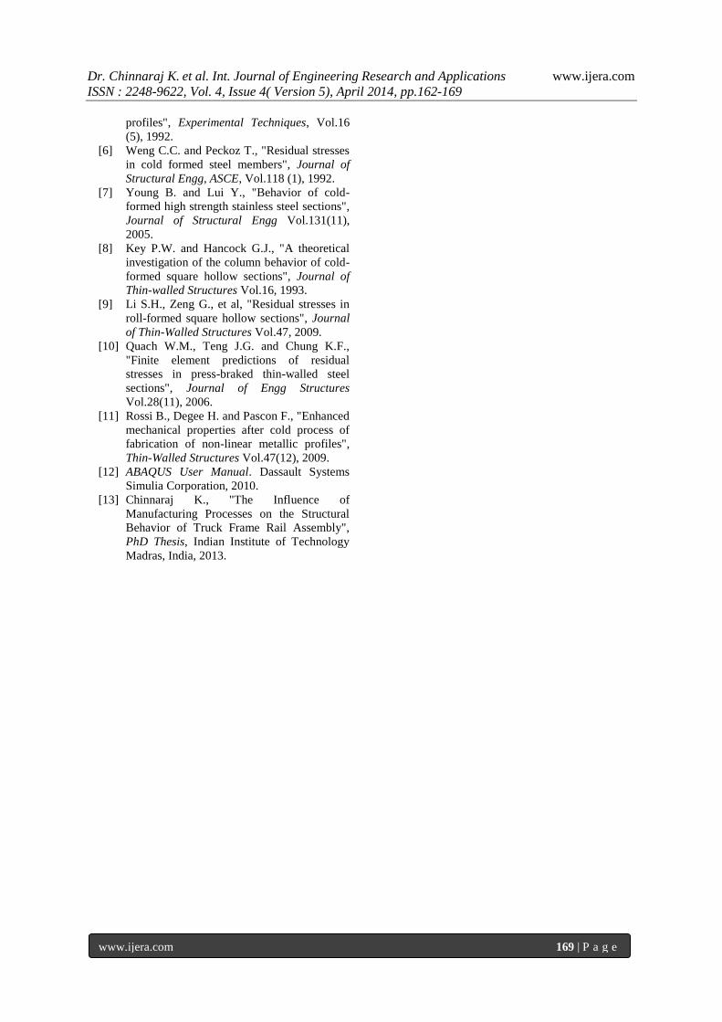
Similarly, the through thickness residual stress results
obtained from numerical simulation of press formed
corner sections in transverse as well as longitudinal
directions are compared with the experimentally
measured residual stress results of formed corner
sections with (r/t) ratios of 2.5 and 3.5 are shown in
Fig. 16 - 19 respectively.
Fig. 16 Experimental vs. numerical transverse residual stresses for
corner section with (r/t) ratio - 2.5
Fig. 17 Experimental vs. numerical longitudinal residual stresses
for corner section with (r/t) ratio - 2.5
Fig.18. Experimental vs. numerical longitudinal residual stresses
for corner section with (r/t) ratio - 3.5
Fig.19. Experimental vs. numerical longitudinal residual stresses
for corner section with (r/t) ratio - 3.5
From the figures, it is observed that the non-linear
zigzag variation in through-thickness residual stresses
from FE simulation is closely in agreement with
Dr. Chinnaraj K. et al. Int. Journal of Engineering Research and Applications www.ijera.com
ISSN : 2248-9622, Vol. 4, Issue 4( Version 5), April 2014, pp.162-169
www.ijera.com 168 | P a g e
experimentally measured residual stresses; although
the experimentally measured peak transverse residual
stresses at depths are slightly lower than finite
element predicted peak residual stress results. Again
this could be attributed to the stress relaxation due to
layer removal during electrolytic polishing process.
In both numerical and experimental methods, the
maximum compressive residual stresses in transverse
and longitudinal directions are observed to be
occurring at a location slightly away from neutral
axis towards the inner corner surface. The magnitude
of maximum compressive stress in inner half
thickness is observed to be more than the magnitude
of maximum tensile stress in outer half thickness of
corner section.
Further, it is observed that the change in direction
of residual stresses do not occur on the mid-section,
but on the section slightly towards inner corner
surface due to the effect of neutral axis shift in bends
with small radius of curvature. It is observed that in
both numerical and experimental methods, the shift
in neutral axis towards inner corner surface is much
severe for lower corner radius to thickness ratio
sections while comparing with higher corner radius to
thickness ratio sections.
VI. SUMMARY AND CONCLUSIONS In this investigation, coiling-uncoiling and press
forming process were numerically simulated with the
help of ABAQUS software and the numerically
predicted residual stresses were validated with the
experimentally measured stress values.
The study results in frame rail web and flange
sections revealed that the through-thickness residual
stresses follow non-linear distribution with maximum
stresses occurring at plastic region away from the
elastic core and at the surface.
Similarly, the study results in frame corner section
revealed that the longitudinal and transverse residual
stresses follow non-linear distribution with maximum
stresses occurring at a depth close to neutral axis.
Hence it is concluded that the consideration of
surface residual stresses alone would not be sufficient
for the structural behavior analysis of cold formed
frame sections.
From the residual stress distribution, it is worth to
note that the mid-section residual stress changes it
direction at a section slightly away from mid-section
towards inner corner and not exactly at mid-section
due to natural shift in neutral axis during press
forming process. Also the change in residual stress
directions in inner and outer quarter thickness of
corner sections is mainly due to elastic spring back
effect after forming process.
It is also found that the maximum transverse and
longitudinal residual stresses in inner half thickness
of corner sections are always higher than the
maximum residual stresses observed in outer half
thickness of corner sections. The excessive cold
working in inner half thickness due to smaller bend
radius than the outer half thickness is one of the
reasons for this observation. It is observed that the
trends and values of experimentally measured
residual stresses in forming direction (transverse
direction) for different corner radius to thickness
ratios (r/t) are in agreement with numerically
predicted residual stresses.
Whereas in the longitudinal direction
(perpendicular to forming direction), while the trends
of experimental and numerical residual stresses were
observed to follow the same pattern, slight deviations
were observed in longitudinal residual stress values
and its direction in the inner surface of corner
sections.
Apart from the residual stresses, the associated
equivalent plastic strains due to coiling-uncoiling and
cold forming processes also found to be increasing
with decrease in coil diameters and (r/t) ratios
respectively. Since these residual stresses along with
corresponding equivalent plastic strain values reveal
the deformed state of web, flange and corner
sections, these parameters in combination with virgin
material stress-strain relationships would be useful
for defining initial conditions of frame rail sections
for further fatigue behavior analysis.
ACKNOWLEDGMENT The authors thank Prof. Kesavan Nair and
Mr. Chari, XRD Lab, Indian Institute of Technology
Madras for their invaluable support extended during
X-ray diffraction measurement. The authors also
thank Dr. N.Saravanan, Head - Engineering and
Dr.Venkat Srinivas, Platform Director - Trucks,
Ashok Leyland Technical Centre for their continuous
support and allowing the authors to carry out this
work at Ashok Leyland Technical Centre.
REFERENCES [1] Quach W.M. “Residual stresses in cold-
formed steel sections and their effect on
column behavior”, PhD thesis, The Hong
Kong Polytechnic University, 2005.
[2] Moen C.D., Igusa T. and Schafer B.W.
“Prediction of residual stresses and strains in
cold-formed steel members”. Thin-Walled
Structures, Vol.46, 2008.
[3] Weng C.C. and White R.N., "Residual
stresses in cold-bent thick steel plates",
Journal of Structural Engg. ASCE, Vol.116
(1), 1990.
[4] Weng C.C. and White R.N. “Cold-bending of
thick high-strength steel plates”. Journal of
Structural Engg, ASCE, Vol.116 (1), 1990.
[5] Batista E.M. and Rodrigues F.C., "Residual
stress measurements on cold formed
Dr. Chinnaraj K. et al. Int. Journal of Engineering Research and Applications www.ijera.com
ISSN : 2248-9622, Vol. 4, Issue 4( Version 5), April 2014, pp.162-169
www.ijera.com 169 | P a g e
profiles", Experimental Techniques, Vol.16
(5), 1992.
[6] Weng C.C. and Peckoz T., "Residual stresses
in cold formed steel members", Journal of
Structural Engg, ASCE, Vol.118 (1), 1992.
[7] Young B. and Lui Y., "Behavior of cold-
formed high strength stainless steel sections",
Journal of Structural Engg Vol.131(11),
2005.
[8] Key P.W. and Hancock G.J., "A theoretical
investigation of the column behavior of cold-
formed square hollow sections", Journal of
Thin-walled Structures Vol.16, 1993.
[9] Li S.H., Zeng G., et al, "Residual stresses in
roll-formed square hollow sections", Journal
of Thin-Walled Structures Vol.47, 2009.
[10] Quach W.M., Teng J.G. and Chung K.F.,
"Finite element predictions of residual
stresses in press-braked thin-walled steel
sections", Journal of Engg Structures
Vol.28(11), 2006.
[11] Rossi B., Degee H. and Pascon F., "Enhanced
mechanical properties after cold process of
fabrication of non-linear metallic profiles",
Thin-Walled Structures Vol.47(12), 2009.
[12] ABAQUS User Manual. Dassault Systems
Simulia Corporation, 2010.
[13] Chinnaraj K., "The Influence of
Manufacturing Processes on the Structural
Behavior of Truck Frame Rail Assembly",
PhD Thesis, Indian Institute of Technology
Madras, India, 2013.