investigation of methods for evaluating unwoven …
TRANSCRIPT

U N I T E D STATES D E P A R T M E N T OF A G R I C U L T U R E - FOREST SERVICE - FOREST P R O D U C T S L A B O R A T O R Y . M A D I S O N , WIS.
INVESTIGATION OF METHODS FOR EVALUATING UNWOVEN
PLASTIC LAMINATES IN FLEXURE GLASS-FIBER-REINFORCED
February 1964
FPL-024
This Report Is One of a Series Issued in Cooperation with the
PLASTICS FOR FLIGHT VEHICLES of the Departments of the AIR FORCE, NAVY, AND COMMERCE
MIL-HDBK-17 WORKING GROUP ON
INVESTIGATION OF METHODS FOR EVALUATING UNWOVEN GLASS-
FIBER-REINFORCED PLASTIC LAMINATES IN FLEXURE 1
KARL ROMSTAD, Engineer
2Fores t Products Laboratory, Fores t ServiceU. S. Department of Agriculture
Abstract
Three plastic laminates reinforced with unwoven, unidirectional glass fibers were evaluated over varying spans under both midpoint and two-point loading in an effort to adapt or improve presently accepted flexure test procedures for these materials. nose, length of overhang, and different two-point loading systems on properties of 1/8-inch laminates.
Also investigated were the effects of radius of loading
The results of these evaluations have indicated that present test methods for reinforced plastics often result in failures that do not accurately evaluate the outer fiber strength of the material. values are lower than would be expected if true outer fiber failures had occurred.
Consequently, modulus of rupture
It was found that horizontal shear failures could be eliminated by using a specimen with a span-depth ratio greater than 16. For a long specimen, however, a correction factor must be applied to the conventional moment expression to include the effect of horizontal components of force at the reaction supports. Compression failures beneath the load points were
1This Note, FPL-024, is another progress report in the series (ANC-17,Item 60-1) prepared and distributed by the Forest Products Laboratory under U.S. Navy Bureau of Naval Weapons Order No. 19-64-8004 WEPS and U.S. Air Force Contract No. 33(657) 63-358. Results here reported are preliminary and may be revised as additional data become available.
Wisconsin.
2 Maintained at Madison, Wis., in cooperation with the University of
FPL-024
By
eliminated either by using a 0.01-inch-thick metal plate beneath a loading nose of 1/8-inch radius, increasing the loading nose radius, or increasing the specimen span-depth ratio.
Introduction
Present techniques for obtaining modulus of rupture values for plastic laminates reinforced with unwoven glass fibers often result in data that do not represent the strength capacity of the outer fibers. reinforcement have axial strengths (strength parallel to fiber) very high in proportion to transverse and interlaminar shear strength. Extremely high loads are required to initiate outer fiber failures at the presently accepted span-depth ratio range for these types of reinforced plastics. These loads often result in transverse or interlaminar shear failures prior to outer fiber tension or compression failures.
Theory presented in Forest Products Laboratory Report No. 1910 ( 1 ) shows how shear failures are related to span-depth ratio for an orthotropic material such as wood. If this theory can be applied to reinforced plastics, it would be expected that an increase in span-depth ratio would reduce the possibility of a shear failure.
Plastics with unwoven
3
A recent paper ( 2 ) investigated span-depth ratios up to 70:l on a material with highly unidirectional strength properties. This paper points out that measurements of modulus of elasticity are in error when a short span is used and shear deformations are not taken into account. The authors recommended that serious consideration be given to using two-point loading instead of the simple beam test under midspan load to obtain flexural properties.
In 1945, ASTM Committee D-20 published results of experiments on flexural properties of plastics ( 7 ). decrease in computed modulus of rupture with an increase in span-depth ratio and that the radius of the loading nose has little effect on computed modulus of rupture. However, none of the materials evaluated had the characteristics of present high-strength plastics.
The Committee concluded that there is a slight
A more extensive investigation of experimental variables was presented by Westwater ( 6 ). shortening, horizontal thrust, and large slopes of the neutral axis.
He analyzed mathematically the corrections for span He also
3 Underlined numbers in parentheses refer to Literature Cited at the end of this report.
FPL-024 -2-
did experimental evaluation on the effect of overhang at the ends of the beam and the effect of the radii of the loading edges. horizontal thrust should be considered when span-depth ratios of 16 and greater are used. variables.
This work showed that
Only midspan loading was used in his investigation of test
This study was undertaken at the Forest Products Laboratory in cooperation with the Military Handbook-17 Working Group and the Minnesota Mining and Manufacturing Company to investigate and, if possible, to adapt or improve the present method of testing plastic laminates reinforced with unwoven, unidirectional glass fibers. The following variables were considered:
1. Span-depth ratios from 8 to 40.
2. Midpoint and third-point loading at several different spans.
3. Varying the loading nose radius from 1/8 to 1 inch on the strongest shear strength material at a 16:l span-depth ratio.
4. Varying the length of overhang as a percent of the span while using two-point loading on specimens that fail in interlaminar shear.
5. Symmetrical two-point loading systems in which the distance between load points was varied on a 3-inch span and compared with specimens loaded at the midpoint on the same span.
The modulus of rupture ideally represents the strength of the outer fibers in bending.material stressed beyond the elastic range, it should not be used as a measure of flexural strength if the failures do not occur in the outer fibers.
While modulus of rupture is admittedly a ficticious quantity for
Description of Mater ial
Three 36- by 36-inch plastic laminate panels, 1/8 inch in thickness, reinforced with unwoven unidirectional glass fibers, were furnished by the Minnesota Mining and Manufacturing Company. system and provides experimental material which has three levels of shear strength in a matrix surrounding "E"f type glass fibers.
Each of these panels has an epoxy-resin
FPL-024 -3-

Nominal uncured resin content (Pct. by weight)
Number of plies
Orientation of fibers
Time to close press (Min.)
Cure:Press temperature (°F.)
Pressure in press (P.s.i.)
Total time in press (Min.)
Postcure:Time (Hr.)
Temperature (°F.)
Resin type
B CA
3535 38-1/2
14 14 12
. . . . . . . . all parallel. . . . . . . . . . . . . . . .
5 Immediately Immediately
310 300
50 50
20 20
16 16
280 350
310
100
30
16
280
Data obtained at the Forest Products Laboratory include:
Resin type
CBA
Average thickness (In.) 0.132 0.138 0.132
Resin content from ignition test (Pct. by weight) 33.4 37.3 37.5
Specific gravity 1.85 1.84 1.79
Bar c o 1 hardness 68 70 65
Five replicate specimens were prepared for each evaluation. were stored for at least 2 weeks at 74° F. and 50 percent relative humidity and were then tested at room temperature and conditioning.
The specimens
FPL-024 -4-
Testing
The specimens were tested flatwise in a mechanical testing machine. deflection was measured with a dial gage reading to 0.001 inch. of the dial was placed in contact with the bottom of the specimen at the center of the span, and the dial was supported on the reaction base. this static-bending apparatus is shown in figure 1. head travel was controlled so that the rate of outer fiber strain was about 1 percent per minute. recorded until the specimen failed.
MidspanThe spindle
A picture of The rate of testing machine
Simultaneous readings of load and deflection were
Span-Depth Ratio
Span-depth ratio is defined here as the distance between the reaction supports divided by the depth (thickness) of the specimen. of specimens loaded at midspan were 8, 12, 16, 32, and 40 and for specimens loaded at the third points were 16, 24, 32, and 40. There were no adjustments made in span for small variations in thickness of the separate specimens.16 and less and 1/2 inch at span-depth ratios greater than 16.
Span-depth ratios
The width of the specimens was 1/4 inch at span-depth ratios of
Loading
Two-point loading was achieved by inserting 1/4-inch-diameter steel rods beneath a wooden block at a specified distance apart for applying loads at third-span points of any given span. in figure 2. located on a given span at a distance from the reaction supports of one-thirdof the span length. Mechanical properties and modes of failure of specimens having span-depth ratios of 16, 32, and 40 were determined for midpoint and third-point loading.
A photograph of this apparatus is shown Third-point loading is defined as two points symmetrically
Loading Nose Radii
Contact points of the reaction supports having a 1/8-inch radius were used for all tests. depth ratio on each of the three laminates was 1/8 inch, while a separate series of tests was run on the epoxy type C resin where a 0.01-inch metal plate was placed beneath the load points to obtain a less critical load concentration.by using the metal plate beneath the load points led to a series of tests on
The radius of loading nose used in evaluating effects of span-
The increase in computed modulus of rupture that resulted
FPL-0 24 -5-

the same material in which the loading nose radius was varied from 1/8 to 1 inch. These tests were conducted under midpoint loading on 1/2-inch-wide specimens having the present standard 16:1 span-depth ratio.
Length of Overhang
A separate series of tests was run using the epoxy types B and C laminates to evaluate the effect of length of overhang on mechanical properties of specimens that fail in interlaminar shear. span-depth ratio, it appeared that the truest interlaminar shear failures occurred in specimens of 16:1 span-depth ratio loaded symmetrically at the one-third points. Percent overhang is defined as the ratio (in percent) length of overhang to span length. overhangs ranging from 25 to 200 percent.
While running the tests evaluating
Specimens of 1/2-inch width were tested with
Different Two -Point Loading Systems
In general, the failures that occurred in third-point loading were rather complex.symmetrical two-point loading systems where the distance from the reaction support to the load point was varied for a given span. distance to the span was called R . Thus, a specimen loaded at the midpoint would have an R value of 0.5. tested on 1/2-inch-wide specimens of epoxy type B laminate at a 24:l span-depth ratio. more uniform load distribution.
Because of this, a series of tests was set up with different
The ratio of this
The effect of four different ratios of R was
A thin metal plate was placed beneath the load points to achieve
Presentation of Data
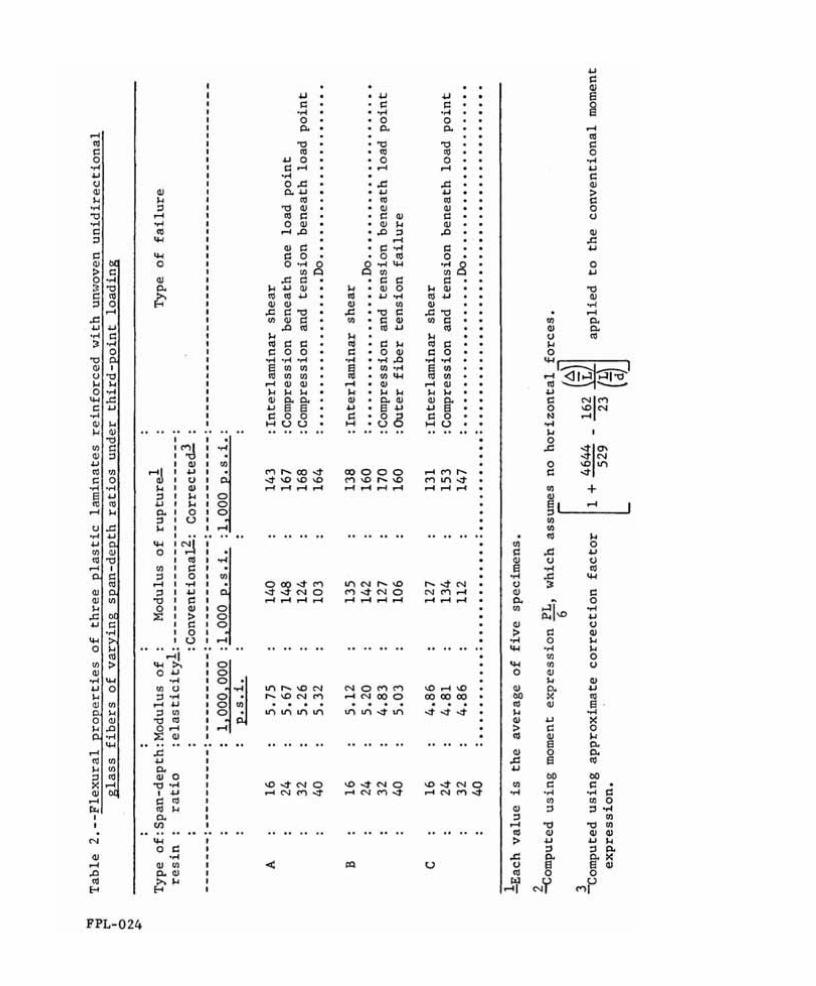
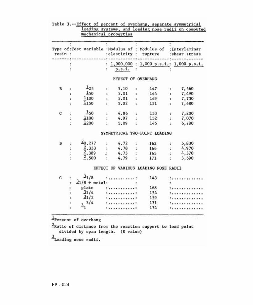
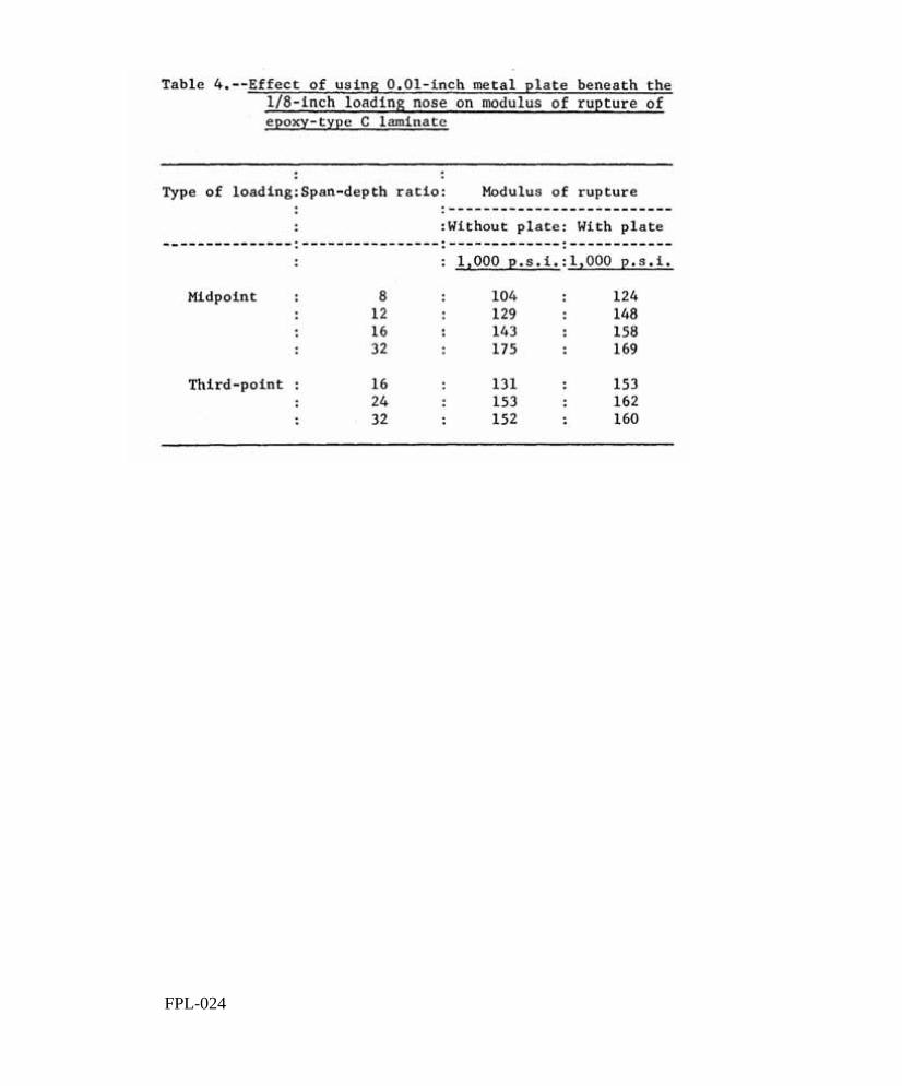
Tables 1 and 2 present data obtained on each of the three laminates at various span-depth ratios and also describe the type of failure that occurred at maximum load, affected by the percent of overhang, the radius of loading nose, and the distance of the load points from the reaction supports on a given span. Table 4 gives modulus of rupture values for epoxy type C laminate showing the effect of using a 0.01-inch metal plate beneath the loading nose at various spans under both midpoint and third-point loading.
Table 3 presents data on mechanical properties as they are
Figures 3 and 4 show the significant effect on modulus of rupture values of applying a correction factor to include the added moment due to developed
FPL-0 24 -6-
horizontal forces at span-depth ratios greater than 16. were obtained by two methods; one solved the differential equation of a beam with developing horizontal forces, and the other was an approximate form found using the standard small deflection theory. are plotted in figures 5 and 6 and show that good agreement was obtained between the two methods.
Correction factors
These correction factors
Figures 7 and 8 show how the mode of failure changes as the span-depth ratio is increased on epoxy type A and B specimen loaded at the midpoint and at the one-third points. Figures 9 and 10 show corrected modulus of rupture values at the different span-depth ratios and also describe the types of failure that occurred on all three materials.
A comparison of modulus of elasticity values over varying spans for midpoint versus third-point loading is shown in figure 11 for epoxy type B laminate.
Figure 12 shows how mechanical properties are affected by different setups of two-point loading on specimens that fail in interlaminar shear when loaded at the one-third points and in combined tension and compression when loaded at midspan. variations in percent overhang on specimens that fail in interlaminar shear.
Figure 13 illustrates how these properties are affected by
Figure 14 shows large differences in modulus of rupture values that result simply by placing a thin metal plate beneath the loading nose. This shows that large discrepancies exist both in midpoint and third-point loading, especially at short spans, on type C laminate. Shown in figure 15 are the differences in modulus of rupture values obtained by changing the loading radius from 1/8 to 1 inch on type C laminate.
Analysis of Data
The present method of testing reinforced plastic specimens in bending, as described in Federal Test Method Standard No. 406, Method 1031, and ASTM D 790-59 T, recommends midpoint loading using a 16:1 span-depth ratio. For a specimen 1/8 inch thick, it recommends a 1/2-inch width and a loading nose having a minimum radius of 1/8 inch and a maximum of 3/16 inch. However, these standards were set up for materials with a much lower strength than the present unwoven glass-reinforced plastics. questionable validity of the data and failures obtained using this procedure, the present study was set up to investigate some of the variables present in the flexural testing of reinforced plastics.
Because of the
FPL-0 24 -7-
Span-Depth Ratio
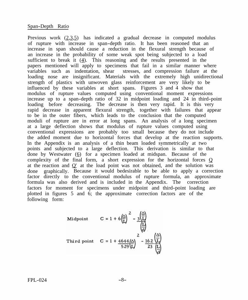
Previous work ( 2 , 3 , 5 ) has indicated a gradual decrease in computed modulus of rupture with increase in span-depth ratio. increase in span should cause a reduction in the flexural strength because of an increase in the probability of some weak spot being subjected to a load sufficient to break it ( 4 ). This reasoning and the results presented in the papers mentioned will apply to specimens that fail in a similar manner where variables such as indentation, shear stresses, and compression failure at the loading nose are insignificant. strength of plastics with unwoven glass reinforcement are very likely to be influenced by these variables at short spans. modulus of rupture values computed using conventional moment expressions increase up to a span-depth ratio of 32 in midpoint loading and 24 in third-pointloading before decreasing. It is this very rapid decrease in apparent flexural strength, together with failures that appear to be in the outer fibers, which leads to the conclusion that the computed moduli of rupture are in error at long spans. at a large deflection shows that modulus of rupture values computed using conventional expressions are probably too small because they do not include the added moment due to horizontal forces that develop at the reaction supports. In the Appendix is an analysis of a thin beam loaded symmetrically at two points and subjected to a large deflection. This derivation is similar to that done by Westwater ( 6 ) for a specimen loaded at midspan. Because of the complexity of the final form, a short expression for the horizontal forces Q at the reaction and Q' at the load point was not obtained, and the solution was done graphically. factor directly to the conventional modulus of rupture formula, an approximate formula was also derived and is included in the Appendix. factors for moment for specimens under midpoint and third-point loading are plotted in figures 5 and 6; the approximate correction factors are of the following form:
It has been reasoned that an
Materials with the extremely high unidirectional
Figures 3 and 4 show that
The decrease is then very rapid.
An analysis of a long specimen
Because it would bedesirable to be able to apply a correction
The correction
FPL-024 -8-
The early increase in apparent flexural strength can be explained by observing the change in mode of failure as the span increases. at short spans the failures are either compression beneath a load point due to the intensity of the load required to initiate an outer fiber failure or inter-laminar shear in the neutral plane. As the span increases, smaller loads are required to initiate outer fiber failures and, therefore, loading nose compression and interlaminar shear stresses become less critical, remain relatively small up to a span-depth ratio of about 16 and, as the span increases, there is a resulting increase in computed conventional modulus of rupture.
Figures 7 and 8 show that
Deflections
Figures 9 and 10 show that the computed modulus of rupture value in midpoint or third-point loading at a 16:1 span-depth ratio is in the neighborhood of 130,000 to 145,000 pounds per square inch. By testing at span-depth ratios of 24 and 32 and applying the correction factor to the conventional moment, flexural stresses of 160,000 to obtained on plastic laminates reinforced with unwoven glass fibers.
175,000 pounds per square inch may be
Midpoint and Third-Point Loading
Modulus of rupture values obtained on a given span should be greater for midpoint loading than for a beam loaded at the one-third points according to Tucker ( 4 ). simultaneously across one-third of the beam length in a beam loaded at the one-third points, there is more chance of a weak spot being subjected to a load sufficient to break it than in a centrally loaded beam where the maximum moment occurs at only one point. outer fibers and is independent of compressive stresses beneath the load points, shear stresses, and indentation of the specimen. Tables 1 and 2 show that modulus of rupture values were, in general, about the same for both midpoint and third-point at span-depth ratios of 16, 24, and 32, while at a span-depth ratio of 40, the centrally loaded specimens had greater modulus of rupture values. This may indicate that compressive stresses beneath the load points had an influence on centrally loaded specimens at short spans. At longer spans, the local stresses beneath the load points became less critical and modulus of rupture values became largest for centrally loaded specimens as Tucker had reasoned. influenced by shear stresses at span-depth ratios of 16 and 24, while at the longer span-depth ratios, the failures often appeared to be influenced by local stresses beneath the load points. occurred in both midpoint and third-point loading at each of the spans tested.
He reasoned that, since the maximum moment occurs
This reasoning only applies if failure is in the
The specimens loaded at the one-third points were
Figures 7 and 8 show typical failures that
FPL-024 -9-
Figure 11 shows a comparison of modulus of elasticity values over varying spans for both midpoint and third-point loading, At extremely short spans, the modulus of elasticity values for centrally loaded specimens are considerably in error, probably due to the effect of shear deformations and indentation at the supports. little difference in modulus of elasticity values.
Above a 16:1 span-depth ratio, there is relatively
While third-point applies a more uniform loading condition to the specimen, it also creates larger shear stresses on a given span and for a given moment, which cause interlaminar shear failures. become very large, and the failures appear to be due to local stresses beneath the load points with some evidence of outer fiber tension failure. In midspan loading, the local stresses were probably most severe at short spans, while at longer spans the failures appeared to be predominately outer fiber tension and compression. The complex failures that occurred in third-point loading led to a series of tests in which the distance between load points was changed on a given span.
At longer spans, the deflections
Symmetrical Two -Point Loading Systems
A test series was set up using three ratios of the reaction support to load point distance divided by the span length. these specimens were compared with a group of specimens loaded at midspan where the R value is 0.5. 24:1 span-depth ratio. third-point loading and outer fiber failures under midspan loading. shows the computed mechanical properties of modulus of rupture, interlaminar shear stress at failure, and modulus of elasticity. at midspan appeared to fail primarily in the outer fibers with no visual evidence of interlaminar shear failures. The results of these tests indicated that the two-point loading systems used in this series of tests imposed stress conditions that resulted in failure by other mechanisms than outer fiber tensile or compressive fracture. loading nose may eliminate the problems of local stresses that often initiated failure on these specimens.
This ratio was called R, and
The tests were on epoxy type B laminate at a Similar specimens had exhibited shear failures under
Figure 12
Only the specimens loaded
Another series of tests with a larger radius of
Length of Overhang
Basically, shear stress should not exist beyond the outermost support in a simple beam test. beams loaded symmetrically at the one-third points on a 2-inch span, the failure propagated from one of the load points to the extreme end of the specimen
However, when interlaminar shear failures occurred in
FPL-024 -10-
beyond the support. Photoelastic methods have shown that shear stress does exist beyond the supports, and it seems possible that the shear area provided beyond the support may affect the load required to initiate shear failures which propagate to the extreme ends of the specimen.
Figure 13 shows the results of increasing the length of overhang on computed mechanical properties for epoxy types B and C, the weakest and strongest shear strength laminates tested. influenced by length of overhang, it is indicated that the stress required to cause failure beyond the support does not occur until failure has already begun within the span.
Because strength was not strongly
It was possible to extend the overhang enough so that the failure did not extend to the end of the specimen. did not produce any pronounced effect on modulus of elasticity or strength.
However, the influence of the length of overhang
Loading Nose Radius
Because of the difficulty of obtaining a true flexure failure at any span in two-point loading and because extremely high loads initiate compression failures beneath the load points on short span, centrally loaded specimens, it was decided to investigate the effect the radius of loading nose had on standard specimens at a 16:1 span-depth ratio. Also, a separate series of tests was run on the epoxy type C laminate using a thin metal plate beneath the load point at various span-depth ratios.
Figure 14 shows the influence of a thin metal plate on computed modulus of rupture values. where loads are extremely high and compression failures occur beneath the load points. failure is smaller, the plate has little effect on rupture values.
The effect of the plate is most pronounced at short spans
At longer spans, where the load required to initiate outer fiber
The radius of the loading nose (fig. 15) appears to have a pronounced effect on modulus of rupture values. radius was about 20 percent greater than that obtained using a 1/8-inch radius loading nose. 1/8-inch loading nose was 17 percent larger than the value obtained using the 1/8-inch loading nose alone. The results of these tests indicate that the values of 170,000 pounds per square inch obtained at the longer spans are more realistic for modulus of rupture values than the short span values where the failures are not in the outer fibers. It should be noted that the laminate used in testing loading nose radius was epoxy type C, the laminate highest in shear strength. The problem of interlaminar shear failures is
The modulus of rupture obtained using a 1-inch
Also, the value obtained by placing the metal plate beneath the
FPL-024 -11-
primarily a function of span length and, for a material weaker in shear, the span would probably have to be extended so that shear failures do not occur if the true modulus of rupture is to be obtained.
Summary of Results
Results of these tests indicate that modulus of rupture values obtained using present techniques of testing at a 16:1 span-depth ratio do not represent what is believed to be the true strength of the outer fibers. Rather, failure under these loading conditions is usually a result of the interlaminar shear strength or the compressive strength perpendicular to the specimen thickness as it is affected by local compressive stresses beneath the load points.
When the span is increased to lessen the effect of shear stresses and local stresses, the deflections become large, and large horizontal forces develop. These forces contribute significantly to the maximum moment and should be added when span-depth ratios greater than 16 are used. In the Appendix is the solution of the differential equation for a beam loaded symmetrically at two points and subjected to a large deflection. analyses to include the effect of horizontal forces for specimens loaded at the one-third points and at midspan.
Also included are approximate
Tests over increasing span-depth ratios show that corrected modulus of rupture values kept increasing up to a span-depth ratio of 40 under midpoint loading. Longer spans were not tried because deflections were becoming too large to be recorded accurately. 32 and 40 were reached that failures appeared to be in the outer fibers alone and caused by the developed moment. corrected modulus of rupture values increased up to a span-depth ratio of 24 or 32 before decreasing.
Significantly, it was not until span-depth ratios of
Under third-point loading, the
While two-point loading helped achieve a more uniform distribution of load to the specimen, it created greater shear stresses for a given moment on a given span and, subsequently, shear failures occurred more frequently. At longer spans, the intensity of load required for initiating failure is much smaller, and midspan loading does not appear to inflict such critical stresses beneath the loading nose as it does on short spans. The failures of specimens loaded at two points on long spans were complex and often appeared to be initiated by local stresses beneath the load points which the distance between the load points w
j
as varied for a given span; however, the failures that had occurred in third-point loading still occurred, and no good outer fiber failures were achieved.
Another series of tests was run in
FPL-024 -12-
Another series of tests was run in which the length of overhang was increased for a given span on specimens that failed in interlaminar shear. appeared to have resulted in any of the mechanical properties.
No change
By increasing the radius of loading nose on specimens loaded at midspan at a 16:1 span-depth ratio, significant modulus of rupture increases were noted. The radius of loading nose was increased from 1/8 to 1 inch and the modulus of rupture increased from 140,000 to 175,000 pounds per square inch.
Conclusions
The results of this investigation indicate that a satisfactory flexure test for plastic laminates reinforced with unwoven glass fibers could be made on specimens having a 24:1 span-depth ratio and loaded at midspan with a 3/4-inchradius loading nose. the modulus of rupture value to include the effect of horizontal forces. The span-depth ratio should be increased to 32 for third-point loading. work should be done to determine an appropriate radius of loading nose to be used on the specimens loaded at the one-third points.
The appropriate correction factor should be applied to
More
FPL-824 -13-
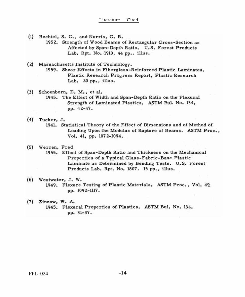
Literature Cited
FPL-024 -14-
Appendix
Computation of Horizontal Components of Force on a Beam Loaded Symmetrically at Two Points Subjected to Large Deflections.
The common moment expression for a beam loaded symmetrically at two points does not include the added moment due to horizontal forces which develop as the beam deflects. These forces can have a significant effect on the moment in a beam and the elastic deflection of the beam when deflections become large with respect to the span. The following derivation uses all the assumptions commonly accepted in beam theory except the assumption that horizontal forces are negligible.
Symbols used are:
Actual moment at midspan Actual recorded load Horizontal component of force at reaction support Horizontal component of force at load point Span length Deflection of centerline of specimen at midspan with relation
Difference between midspan and load point deflection Slope of specimen at support Slope of specimen at load point Equivalent load required to produce deflection, A
to supports
FPL-024 -15-
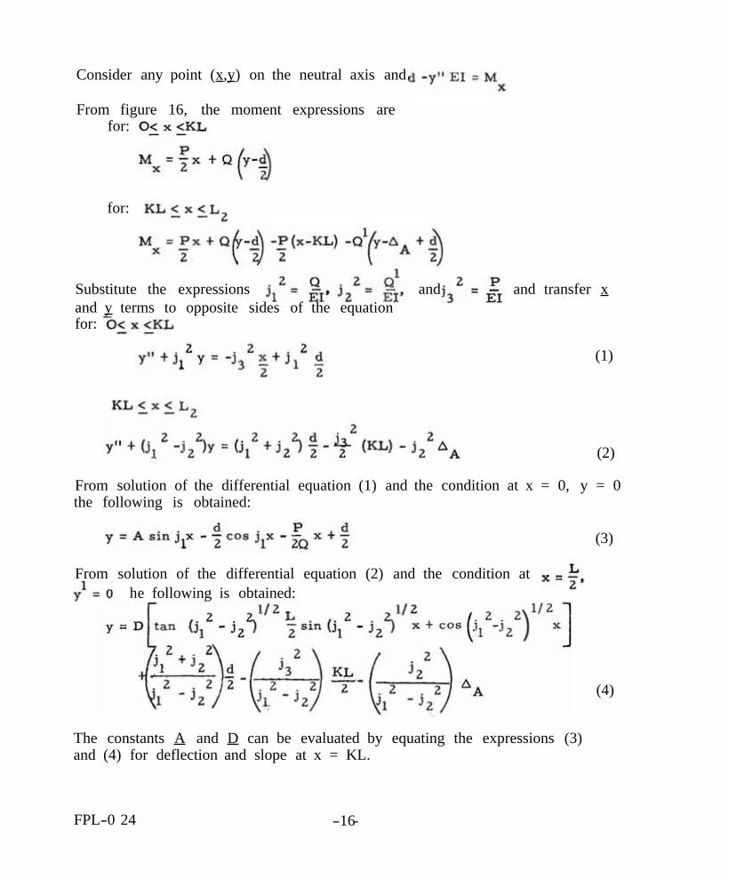
Consider any point ( x , y ) on the neutral axis and
From figure 16, the moment expressions are for:
for:
and transfer x Substitute the expressions and and y terms to opposite sides of the equation for:
From solution of the differential equation (1) and the condition at x = 0, y = 0 the following is obtained:
(3)
From solution of the differential equation (2) and the condition at he following is obtained:
The constants A and D can be evaluated by equating the expressions (3) and (4) for deflection and slope at x = KL.
FPL-0 24 -16-
(1)
(2)
(4)
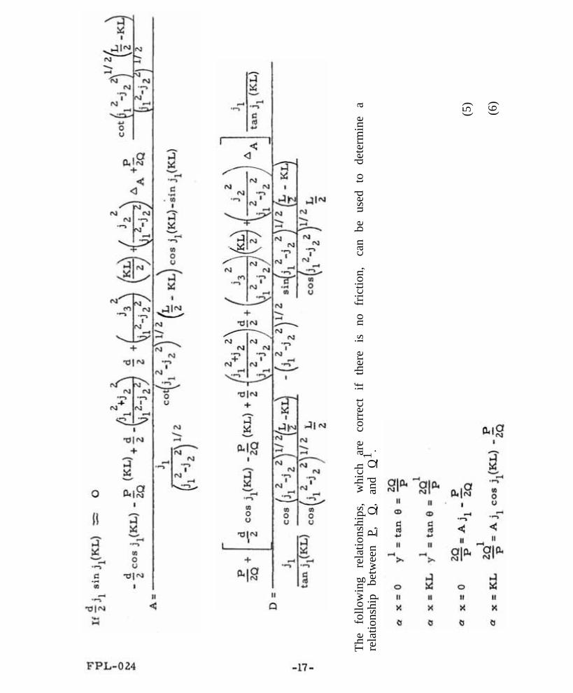
The
follo
win
g re
latio
nshi
ps,
whi
ch
are
corr
ect
if th
ere
is
no
fric
tion,
ca
n be
us
ed t
o de
term
ine
a re
latio
nshi
p be
twee
n P ,
Q
,an
d Q
1 .
(5)
(6)
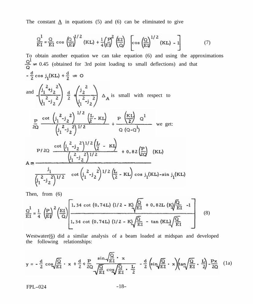
The constant A in equations (5) and (6) can be eliminated to give
To obtain another equation we can take equation (6) and using the approximations 0.45 (obtained for 3rd point loading to small deflections) and that
we get:
Then, from (6)
Westwater(6) did a similar analysis of a beam loaded at midspan and developed the following relationships:
FPL-024 -18-
(7)
and is small with respect to
(8)
(1a)
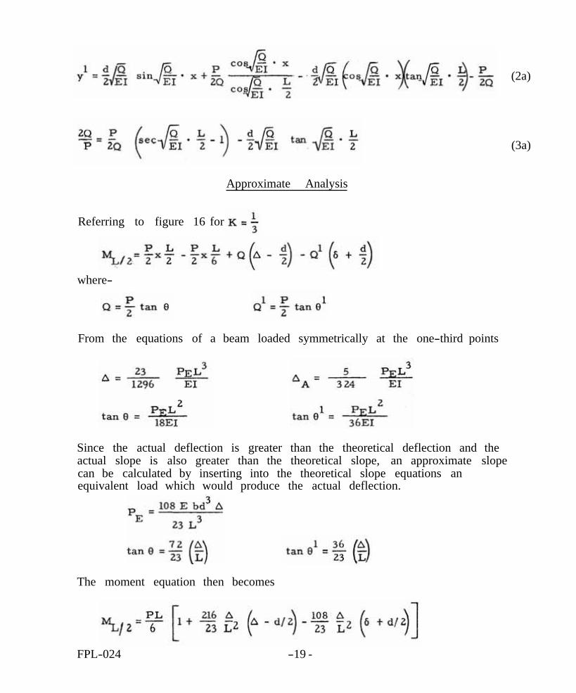
Approximate Analysis
Referring to figure 16 for
where-
From the equations of a beam loaded symmetrically at the one-third points
Since the actual deflection is greater than the theoretical deflection and the actual slope is also greater than the theoretical slope, an approximate slope can be calculated by inserting into the theoretical slope equations an equivalent load which would produce the actual deflection.
The moment equation then becomes
FPL-024 -19 -
(2a)
(3a)
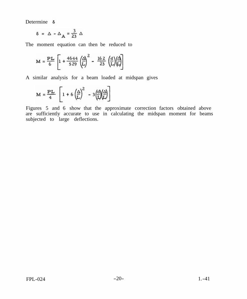
Determine
The moment equation can then be reduced to
A similar analysis for a beam loaded at midspan gives
Figures 5 and 6 show that the approximate correction factors obtained above are sufficiently accurate to use in calculating the midspan moment for beams subjected to large deflections.
FPL-024 -20- 1.-41

FPL-024
FPL-024
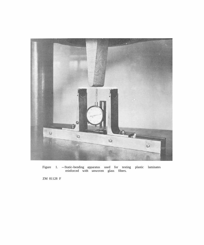
Figure 1. --Static-bending apparatus used for testing plastic laminates reinforced with unwoven glass fibers.
ZM 81128 F
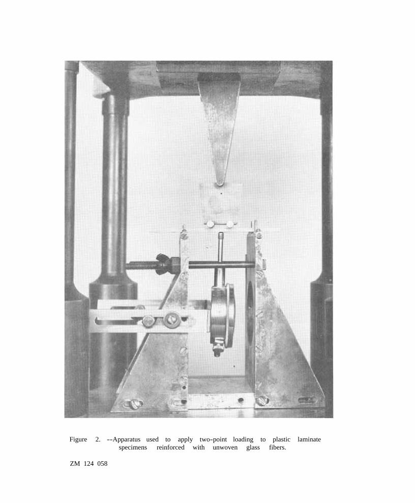
Figure 2. --Apparatus used to apply two-point loading to plastic laminate specimens reinforced with unwoven glass fibers.
ZM 124 058
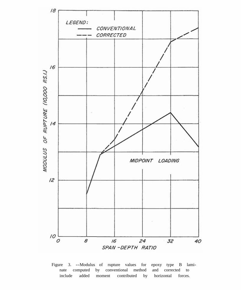
Figure 3. --Modulus of rupture values for epoxy type B lami-nate computed by conventional method and corrected to include added moment contributed by horizontal forces.
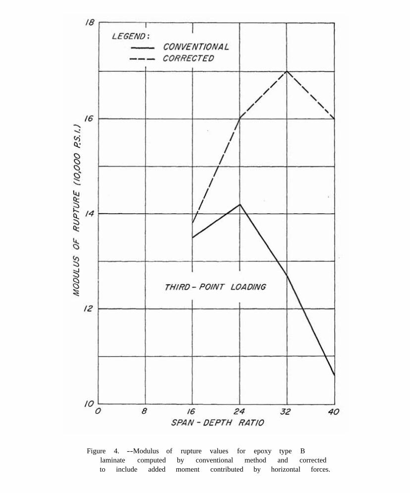
Figure 4. --Modulus of rupture values for epoxy type B laminate computed by conventional method and corrected to include added moment contributed by horizontal forces.
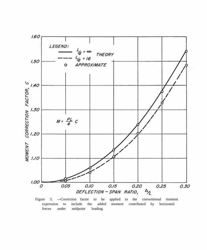
Figure 5. --Correction factor to be applied to the conventional moment expression to include the added moment contributed by horizontal forces under midpoint loading.
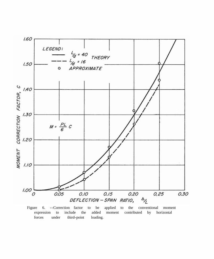
Figure 6. --Correction factor to be applied to the conventional moment expression to include the added moment contributed by horizontal forces under third-point loading.
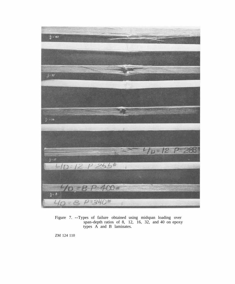
Figure 7. --Types of failure obtained using midspan loading over span-depth ratios of 8, 12, 16, 32, and 40 on epoxy types A and B laminates.
ZM 124 110
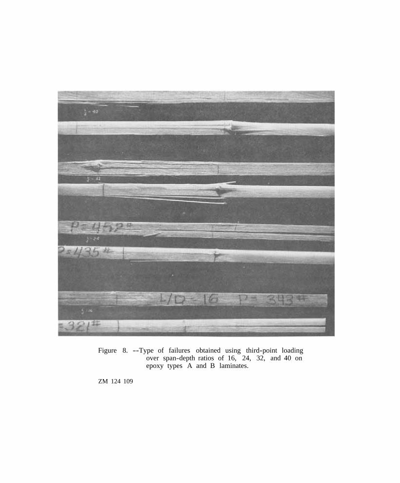
Figure 8. --Type of failures obtained using third-point loading over span-depth ratios of 16, 24, 32, and 40 on epoxy types A and B laminates.
ZM 124 109
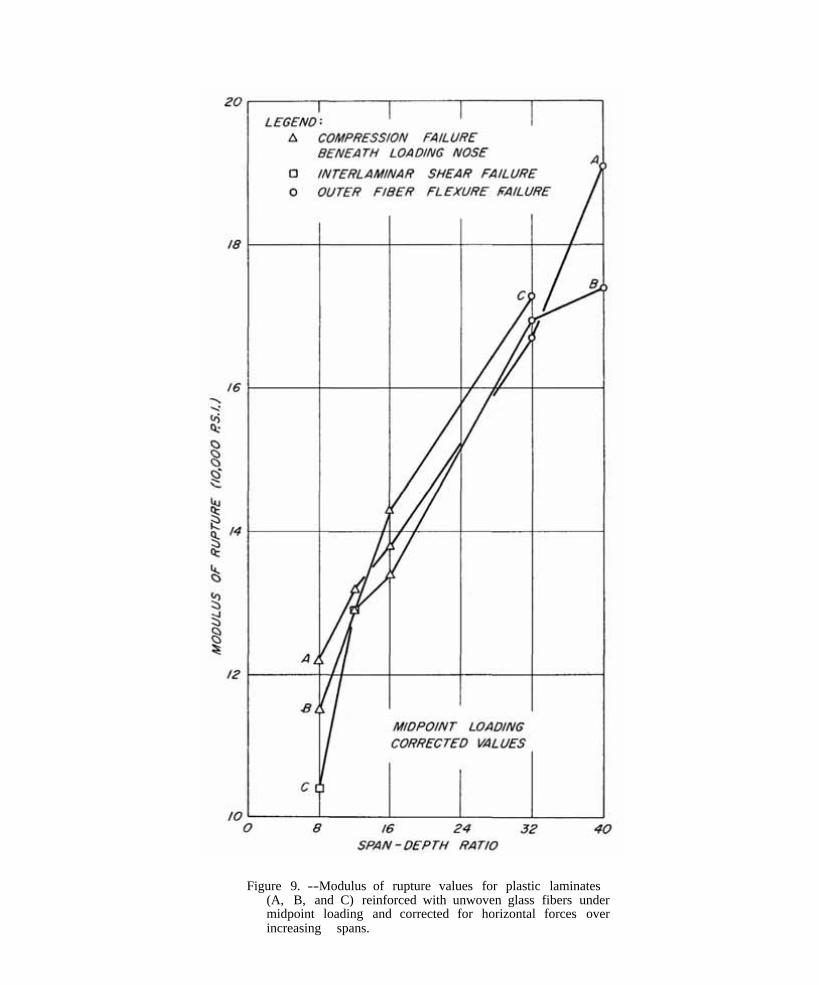
Figure 9. --Modulus of rupture values for plastic laminates (A, B, and C) reinforced with unwoven glass fibers under midpoint loading and corrected for horizontal forces over increasing spans.
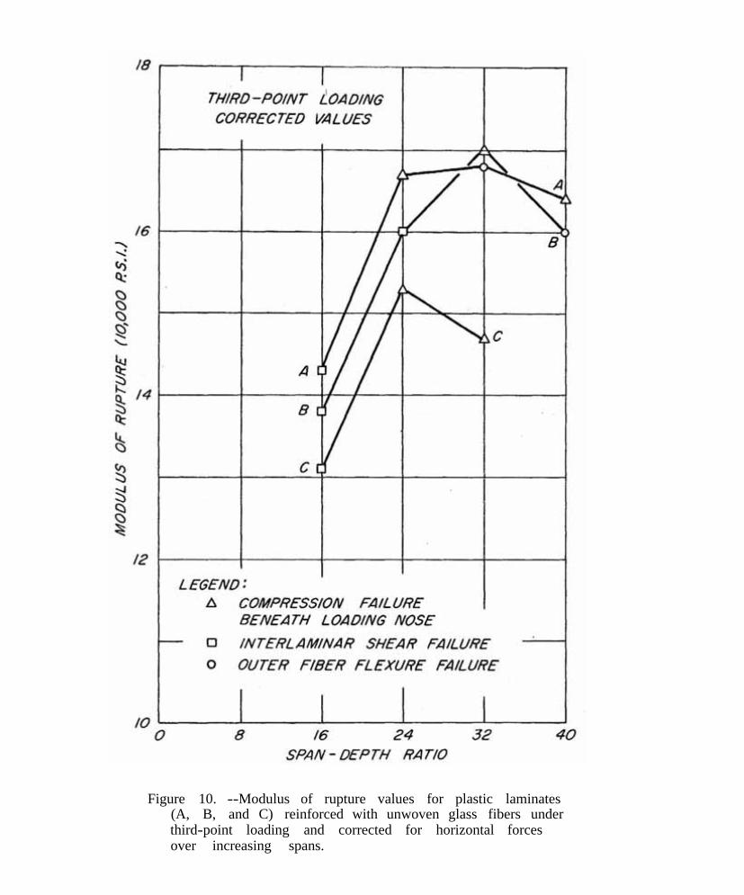
Figure 10. --Modulus of rupture values for plastic laminates (A, B, and C) reinforced with unwoven glass fibers under third-point loading and corrected for horizontal forces over increasing spans.
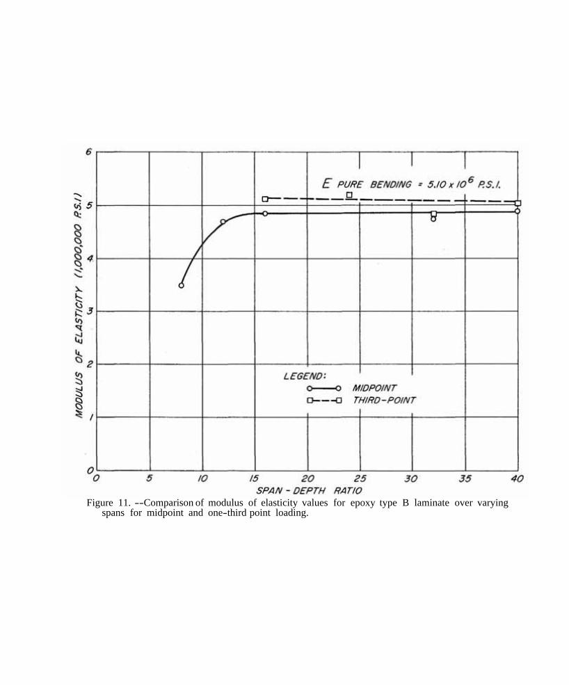
Figure 11. --Comparison of modulus of elasticity values for epoxy type B laminate over varying spans for midpoint and one-third point loading.
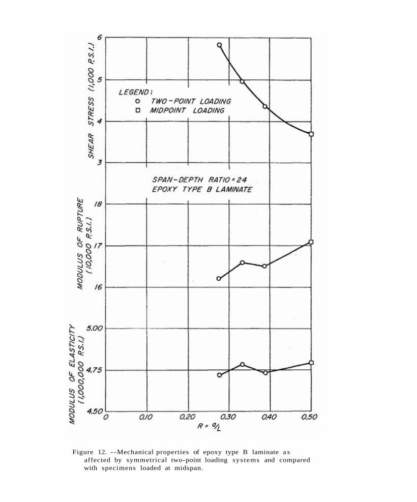
Figure 12. --Mechanical properties of epoxy type B laminate a saffected by symmetrical two-point loading systems and comparedwith specimens loaded at midspan.
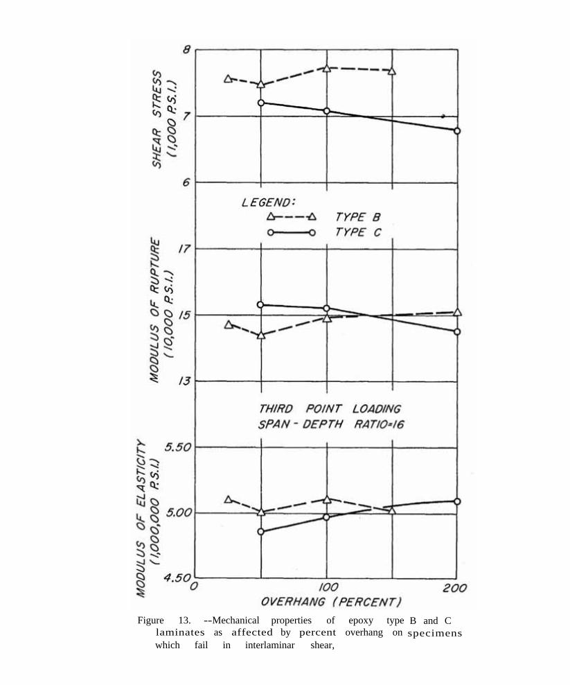
Figure 13. --Mechanical properties of epoxy type laminates as affected by percent overhang on which fail in interlaminar shear,
B and C specimens
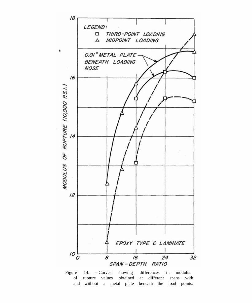
Figure 14. --Curves showing differences in modulus of rupture values obtained at different spans with and without a metal plate beneath the load points.
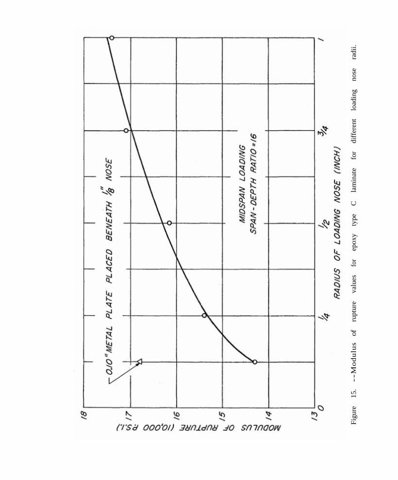
Figu
re
15.
--M
odul
usof
rupt
ure
valu
es
for
epox
y ty
pe
C
lam
inat
e fo
r di
ffer
ent
load
ing
nose
ra
dii.
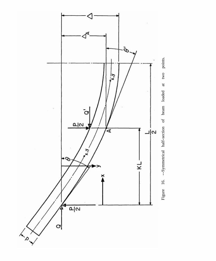
Figu
re
16.
--Sy
mm
etric
al
half-
sect
ion
of
beam
lo
aded
at
tw
o po
ints
.