investigation of the mechanical properties and behaviour
TRANSCRIPT

Cape Peninsula University of TechnologyDigital Knowledge
CPUT Theses & Dissertations Theses & Dissertations
1-1-2008
Investigation of the mechanical properties andbehaviour of hybrid polymer compositesembedded with shape memory alloysOlukayode Lawrence AyodeleCape Peninsula University of Technology
This Text is brought to you for free and open access by the Theses & Dissertations at Digital Knowledge. It has been accepted for inclusion in CPUTTheses & Dissertations by an authorized administrator of Digital Knowledge. For more information, please contact [email protected].
Recommended CitationAyodele, Olukayode Lawrence, "Investigation of the mechanical properties and behaviour of hybrid polymer composites embeddedwith shape memory alloys" (2008). CPUT Theses & Dissertations. Paper 37.http://dk.cput.ac.za/td_cput/37

INVESTIGATION OF THE MECHANICAL PROPERTIES AND BEHAVIOUR OF HYBRID POLYMER COMPOSITES EMBEDDED WITH SHAPE MEMORY ALLOYS
by
OLUKAYODE LAWRENCE AYODELE
Thesis submitted in fulfilment of the requirements for the degree Magister Technologiae: Mechanical Engineering
in the Faculty of Engineering
at the Cape Peninsula University of Technology
Supervisor: Dr. Oscar Philander Co-supervisor: Dr. Salie Mahoi
Bellville June 2008

ii
DECLARATION
I, Olukayode Lawrence Ayodele, declare that the contents of this thesis represent my own unaided work, and that the thesis has not previously been submitted for academic examination towards any qualification. Furthermore, it represents my own opinions and not necessarily those of the Cape Peninsula University of Technology.
Signed June, 2008

Abstract
iii
ABSTRACT
The increasing requirement for light weight constructions and the unsatisfactory performances of
traditional metals and conventional engineering materials, especially in their failure to positively
respond to environmental stimuli, in a demanding environment have made the search for the
development of alternative materials inevitable. Such alternative materials being sought, which
are the so-called adaptive, multifunctional, smart or intelligent composites would facilitate the
realization of some engineering applications that are simply difficult to achieve with the existing
conventional materials.
Composite materials have found increasing applications in construction, aerospace and
automotive industries due to their good characteristics of light weight, improved strength,
corrosion resistance, controlled anisotropic properties, and reduced manufacturing and
maintenance costs. However, there is a growing demand to improve on composite materials to
have “smart" capabilities so as to be able to sense, actuate and respond to the surrounding
environment.
Shape memory alloys (SMAs) are metallic alloys that can undergo martensitic phase
transformations as a result of applied thermomechanical loads and are capable of recovering
permanent strains when heated above a certain transformation temperature. SMAs possess
sensing and actuating functions and have the potential to control the mechanical properties and
responses of their hosts due to their inherent unique characteristics: shape memory effect (SME)
and pseudoelasticity. When integrated into structural components, they perform sensing,
diagnosing, actuating and repair or healing functions, thereby enhancing improved performance
characteristics of their hosts. Amongst the commercially available SMAs, NiTi (Nickel-Titanium)
alloys in forms of wires, ribbons, bars, particles and porous bulks are the most widely used
because of their excellent mechanical properties and superior material characteristics.
Embedding SMAs into composite materials can create smart or intelligent hybridized
composites.
This thesis details an investigation of the mechanical properties and behaviour of the hybridized
composites formed by embedding NiTi SMA wires into 60D polyurethane. The composites were
produced by the vacuum process of manufacturing. The properties of the implanted SMA wires
were enhanced by ageing and pre-straining. Uniaxial tensile and four point bending tests were
conducted to ascertain the significance of embedding SMA wires into the polyurethane host

Abstract
iv
matrix. It was found that the embedded SMA results in an increasing in elastic modulus, tensile
strength and bending stiffness. It was found that these improvements in the properties can not
be sustained at high temperature owing to degradation of interfacial strength between the SMA
and polyurethane as a result of the high recovery stress generated by the SMA upon activation.
Some measures that can ameliorate the interfacial breakdown were suggested.

v
ACKNOWLEDGEMENTS
The time spent completing this research has been an enriching, exciting and exhaustive part of
my life and one that I will never forget. I would therefore like to appreciate the Almighty God for
his blessings and faithfulness without which the objective of this research would not have been
accomplished.
My profound gratitude goes to my supervisor, Dr. Oscar Philander for his guidance, thorough
supervision, and unflinching support to creating conducive environment during the course of this
research. Your motivation at all times cannot be quantified.
I would like to specially thank Prof. G. Oliver and Prof. J. Grizagoridis. Their decisive and
constructive review of my research proposal contributed in no small measure to the realization of
the objective of this research.
I also acknowledge with thanks Mr. Brent Deez of the Department of Industrial Engineering,
University of Stellenbosch, Stellenbosch. He was very helpful during the process of
manufacturing my specimens. My sincere gratitude also goes to Mr Walter Kolhlofer for the
assistance he offered regarding the experimental works.
My appreciation also goes to Mr. Z. Ngewana for the privilege he afforded me to teach while
simultaneously pursuing my studies. I also would like to express my sincere appreciation to Ms
Felicity Harris for making out time to proof-read this thesis despite her busy schedule.
I would also like to thank my research colleague, Mr. W. Mwita for his words of encouragement
at all times. My gratitude also goes to everyone, and in particular Mr. A. K. Raji who has
contributed one way or the other towards the success of this research. I also acknowledge with
thanks the funding received from the Cape Peninsula University of Technology, Bellville.
I must not fail to acknowledge the endurance and good understanding shown by my wife and
my children that I have left at home in Nigeria, for upward of two years while selfishly improving
myself academically in far away South Africa. My sincere gratitude also goes to my entire family,
Gbadebo Aderinto and Engineer Segun Ogunsnaya for the moral and financial support given to
my wife and children.

vi
DEDICATION
.
To my darling wife, Adesola and lovely children, Olasunkanmi, Olalekan, and Olanrewaju

Table of Contents
vii
TABLE OF CONTENTS
Declaration ii Abstract iii Acknowledgements v Dedication vi List of figures x List of tables xii Glossary xiii
CHAPTER ONE: INTRODUCTION 1.1 Motivation 1 1.2 Objectives of the thesis 4 1.3 Structure of the thesis 5
CHAPTER TWO: COMPOSITES, POLYURETHANES AND SHAPE MEMORY
MATERIALS 2.1 Background on composites 6 2.2 Matrix material 9 2.2.1 Polymer matrix 10 2.2.2 Metal matrix 10 2.2.3 Ceramic matrix 10 2.3 Background on polyurethanes 11 2.4 Reinforcements 11 2.4.1 Fibre reinforcements 12 2.4.2 Fibreglass 12 2.4.3 Carbon fibre 13 2.4.4 Aramid fibre 13 2.4.5 Other fibre reinforcements 13 2.5 Background on shape memory materials 13
CHAPTER THREE: LITERATURE REVIEW 3.1 History of shape memory alloys 15
3.2 General properties of shape memory alloys (SMAs) 15
3.3 Characteristics of the martensitic transformation in SMAs 17
3.4 Shape memory effect 19
3.4.1 One-way shape memory effect 20
3.4.2 Two-way shape memory effect 21
3.4.3 Comparison of one-way and two-way shape memory effects 22
3.5 Pseudoelasticity 22
3.6 Damping properties of shape memory alloys 24
3.7 Interfacial properties of SMA based composites 25
3.8 Improvement of the properties of NiTi shape memory alloys 27

Table of Contents
viii
3.9 Shape memory alloy based composites 29
3.10 Applications of NiTi SMAS embedded in polymeric composites 30
3.10.1 Vibration and dynamic response control 32
3.10.2 Stiffness and impact damage control 36
3.10.3 Shape and position control 40
3.10.4 Other Applications of NiTi shape memory alloys 40
3.11 Factors affecting the effectiveness of embedded SMA in SMA based composites
41
CHAPTER FOUR: THERMODYNAMICS OF MARTENSITIC TRANSFORMATION
4.1 Introduction 44
4.2 Thermally induced martensitic transformation 44
4.3 Stress induced martensitic transformation 48
CHAPTER FIVE: MODELLING OF SHAPE MEMORY ALLOY BASED COMPOSITES 5.1 Introduction 51
5.2 Governing equations for banding and deflection of beams 51
5.3 Constitutive relation of a uniform rectangular beam 55
5.4 Constitutive relation of shape memory alloys 57
5.5 Constitutive relation of SMA based composite beam 60
CHAPTER SIX: EXPERIMENTAL WORK 6.1 Introduction 68
6.2 Vacuum casting process 68
6.3 Production of the master parts 68
6.4 Preparation of the mould 69
6.5 Casting of specimens 72
6.6 Ageing of NiTi shape memory alloy wires 74
6.7 Prestraining of NiTi shape memory alloy wires 76
6.8 Time response of NiTi shape memory alloy wire 78
6.9 Pullout test 79
6.9.1 Experimental procedure 79
6.10 Tensile test 80
6.10.1 Experimental procedure 82
6.11 Four point bending test 84
6.11.1 Experimental procedure 85
CHAPTER SEVEN: DISCUSSION OF RESULTS 7.1 Introduction 87 7.2 Effects of ageing and prestraining on NiTi SMA wire 87 7.3 Effect of temperature on pullout load 88

Table of Contents
ix
7.4 Effect of temperature on NiTi SMA wire 91 7.5 Effect of embedding NiTi SMA wire into 60D polyurethane 91 7.6 Effect of volume fraction of NiTi SMA wire on SMA based composites 92 7.7 Effect of activation of NiTi SMA wire embedded into SMA based
composites 93
7.8 Effects of NiTi SMA wire on deformation of SMA/polyurethane composite beams
95
7.9 Effects of NiTi SMA wire on deflection of SMA/polyurethane composite beams
96
7.10 Comparisons of bending stiffness of virgin polyurethane and SMA/polyurethane composite beams
98
CHAPTER EIGHT: CONCLUSIONS AND RECOMMENDATIONS
8.1 Conclusions 101
8.2 Recommendations 102
REFERENCES 105
APPENDICES Appendix A: Crystal structures for the austenite phase and the martensite phase
111
Appendix B: The pseudo elastic effect 112 Appendix C: Effects of ageing and pre-straining on NiTi SMAs 113 Appendix D: Load vs. Extension diagrams to determine pre-strain load 116 Appendix E: Effect of temperature on pullout load 118 Appendix F: Development of equation for deflection of beam 120

List of Figures
x
LIST OF FIGURES Figure 1.1: Schematic illustration of a smart structure 3 Figure 2.1: Schematic illustration of a composite material 8 Figure 2.2: Lamina composite structure 9 Figure 2.3: Honey comb sandwich structure 9 Figure 3.1: Illustration of martensitic reverse transformations 18 Figure 3.2: Crystallographic illustration of the shape memory effect 20 Figure 3.3: Schematic illustration of one-way shape memory effect 20 Figure 3.4: Schematic illustration of two-way shape memory effect 21 Figure 3.5: Schematic illustration of pseudoelastic effect 23 Figure 3.6: Schematic representation of superelasticity 24 Figure 3.7: Basic design concept for a smart composite material 30 Figure 3.8: Effect of SMA layer thickness on beam response 34 Figure 3.9: Effect of martensitic residual strain on beam response 34 Figure 3.10: Effect of 20 % volume fraction and 3% pre-strain of NiTi SMAs on the
natural frequency of a clamped-clamped plate 35
Figure 3.11: Effect of 30 % volume fraction and 3% pre-strain of SMA on natural frequency of a clamped-clamped plate
35
Figure 3.12: Effect of 30 % volume fraction and 5% pre-strain of SMA on natural frequency of a clamped-clamped plate
36
Figure 3.13: NiTi reinforced composite beam 37 Figure 3.14: Effect of number of wires on buckling control 37 Figure 3.15: Effect of pre-strain on buckling control 38 Figure 4.1: Gibbs free energies for the austenite and martensite phase at
constant stress 46
Figure 5.1: Schematic representation of a rectangular beam 51 Figure 5.2: Representative volume of SMA/polyurethane composite beam 61 Figure 5.3: Cross-section of SMA/polyurethane composite beam 62 Figure 6.1: Master part for dog bone tensile test specimen 69 Figure 6.2: Master part for rectangular beam specimen 69 Figure 6.3: Mould box 70 Figure 6.4: Arrangement of mixing cups inside the vacuum chamber 73 Figure 6.5: Experimental set up for pre-straining NiTi SMAs 75 Figure 6.6: Stress versus strain at different ageing temperatures 76 Figure 6.7: Load for 3% pre-strain 77 Figure 6.8: Twisted NiTi SMA wire before activation 78 Figure 6.9: Full shape recovery of the twisted NiTi SMA wire 78 Figure 6.10: Experimental set up for pullout test 80 Figure 6.11: Dog bone virgin polyurethane tensile test specimen 81 Figure 6.12: Dog bone NiTi/polyurethane specimen (single wire) 81 Figure 6.13: Dog bone NiTi/polyurethane specimen (double wire) 81 Figure 6.14: Experimental set up for tensile testing of inactivated SMA/
polyurethane composite 82
Figure 6.15: Experimental set up for tensile testing of activated SMA/ polyurethane composite
83
Figure 6.16: SMA/polyurethane composite beams with fastened strain gauges 84 Figure 6.17: Experimental set up for four point bending test 85 Figure 6.18: Schematic illustration of four point bending test 86 Figure 7.1: Effects of ageing and prestrain on NiTi SMAs 87 Figure 7.2: Effects of ageing temperatures on NiTi SMAs 88 Figure 7.3: Pullout load vs. displacement at room and elevated temperatures 89

List of Figures
xi
Figure 7.4: Stress vs. displacement at room and elevated temperatures 90 Figure 7.5: Effect of embedding NiTi SMA wire into 60D polyurethane 91 Figure 7.6: Effect of NiTi SMA wire volume fraction on SMA/polyurethane
composites 92
Figure 7.7: Effect of temperature on SMA/polyurethane composite beams 94 Figure 7.8: Effects of NiTi SMAs on deformation of SMA/polyurethane composite
beams 95
Figure 7.9: Effects of NiTi SMAs on deflection of SMA/polyurethane composite beams
97
Figure 7.10: Idealization of four point bending test 98 Figure A1: Crystal structure for the austenite phase (body centred cubic lattice) 111 Figure A2: Crystal structure for the martensite phase (simple cubic lattice) 111 Figure B1: Schematic illustration of the pseudo-elastic effect 112 Figure F1: Loading diagram for a beam 120

List of Tables
xii
LIST OF TABLES
Table 5.1: Comparison of major macroscopic modelling of SMA 67 Table 5.2: Comparison of Young’s modulus 67 Table 6.1: Chemical composition of NiTi SMA 72
Table 6.2: Technical data for 60D polyurethane casting resin 72
Table 7.1: Properties of virgin 60D Polyurethane and SMA/polyurethane composites
94
Table 7.2: Effects of NiTi SMA wire on deflection of SMA/polyurethane beams 96
Table 7.3: Slope of the graph of bending load vs. deflection 99
Table 7.4: Comparison of the bending stiffness 100

Glossary
xiii
GLOSSARY
Symbols/Acronyms
Meanings
SA Austenite start temperature
fA Austenite finish temperature
SM Martensite start temperature
fM Martensite finish temperature
CT Equilibrium temperature
T Temperature
U Internal energy
Q Heat exchange
W Work done
V Volume p Pressure
H Enthalpy
G Gibbs free energy AG Gibbs free in austenite phase
MG Gibbs free in martensite phase
0T Initial temperature
MH Enthalpy in martensite phase
AH Enthalpy in austenite phase
MS Entropy in martensite phase
AS Entropy in austenite phase
ξ Martensite volume fraction
ijσ Applied stress
ijε Strain
xσ Stress in x direction
yσ Stress in y direction
zσ Stress in z direction
xε Strain in x direction
yε Strain in y direction
zε Strain in z direction
A Cross sectional area, Austenite phase
M Moment, Martensite phase
R Radius of curvature
P Applied load
E Young’s modulus

Glossary
xiv
I Second moment of area
EI Bending stiffness
ijδ Knonecker delta
Ω Transformation tensor
Θ Thermoelastic tensor
Sξ Stress induced martensite volume fraction
Tξ Temperature induced martensite volume fraction
Lε Maximum recovery strain
mV Volume fraction of matrix
SV Volume fraction of SMA
rσ Recovery stress of SMA
AE Young’s modulus of SMA in austenite phase
ME Young’s modulus of SMA in martensite phase
SE Young’s modulus of SMA
mE Young’s modulus of matrix
mα Thermal coefficient of expansion of matrix
L Length of a beam
µλ, Lame’s constants
Sε Strain of the SMA
mε Strain of the matrix
cε Strain of the composite
cF Axial force on the composite
mF Axial force on the matrix
sF Axial force on the SMA
APT Active property tuning ASC Active shape control ASET Active energy strain tuning CC Clamped-Clamped boundary condition Comp Composite ET Elevated temperature NiTi Nickel_Titanium Nitinol Nickel_Titanium o Subscript for initial value RT Room temperature S Entropy SIM Stress induced martensite SMA Shape memory alloy SMAs Shape memory alloys SME Shape memory effect TIM Temperature induced martensite TWSME Two-way shape memory effect y Deflection of a beam

Chapter 1 Introduction
1
CHAPTER ONE
INTRODUCTION
1.1 Motivation
The need to improve the performance characteristics of engineering materials in their various
applications is engaging engineers and scientists in research activities. The increasing
requirement for light weight constructions and the unsatisfactory performances of traditional
metals and conventional engineering materials, especially in their failure to positively respond to
environmental stimuli, in a demanding environment have made the search for the development
of alternative materials inevitable. Such alternative materials being sought, which are the so-
called adaptive, multifunctional, smart or intelligent would facilitate the realization of some
engineering applications that are simply difficult to achieve with the existing conventional
materials. A significant amount of research has been greatly geared into the development of
smart composite materials in the last several years. The field of smart composite materials is a
broad range of technologies that enable the realization of structural systems that are able to
sense and to control their own behaviour, such that the range of operational performance may
be extended over conventional materials.
Smart or intelligent materials are materials that have inherent sensing, actuating, and controlling
or information processing capabilities in their microstructures. They have the ability to respond to
changes in environmental stimuli such as temperature, electric field, or magnetic field owing to
the inherent intelligence. Some materials that have primitive intelligence inherent in them are
shape memory materials, piezoelectric materials, fibre-optics, magneto-(electro-)strictive
materials, magneto-(electro-)rheological fluids and some functional polymers (Wei, Sandstrom &
Miyakazi, 1998; Turner, 2001). All of these materials have great potential in a variety of
applications, however shape memory materials (shape memory alloys, shape memory polymers,
shape memory ceramics) are the major elements of smart composites because of their unusual
properties of shape memory effect, pseudoelasticity, high damping capacity and adaptive
properties which are due to the reversible phase transitions in the materials.
Smart composite materials and structures are formed by either embedding shape memory
materials into or bonding shape memory materials to host matrices, which are either metallic or
polymeric conventional engineering materials. Smart composite materials and structures
respond to external commands or local change in environmental conditions, with control

Chapter 1 Introduction
2
achieved by shape memory materials that apply localised strains or stresses. The expected
performances of engineering materials which are manifested through formidable characteristics
and better properties could be achieved by the combined excellent features of shape memory
materials and host matrices (Stalmans, 2006).
Amongst the commercially available shape memory materials, shape memory alloys (SMAs)
appear to have significant advantages of excellent performance in the areas of structural
response control, structural shape control, and damping enhancement. SMAs are functional
materials with unique characteristics of shape memory effect and pseudoelasticity (Lau, Poon &
Zhou, 2005). Their remarkable mechanical property features, such as high recovery force to
weight ratio and large recoverable deformation have enabled them to be utilized for actuators
and sensors in a diversity of fields.
Since their discovery, SMAs have been investigated for a variety of applications. Lau, Zhou and
Tao (2002) reported that SMA is most suitable for active control of the development of smart
composite materials and structures. SMA is able to generate a relatively large deformation which
is recoverable upon heating. SMA actuators are plastically deformable while in the low
temperature phase and such deformations could be in the form of bending, twisting,
compressing and stretching. The plastically deformed actuators can revert to their original shape
and size by undergoing an internal phase transformation process through the increase of
temperature.
This shape reformation process generates a thermal-mechanical driving force if the shape
recovery is constrained. In recent years, research into the utilization of SMA actuators for
advanced composite structures for stiffness control, shape control and vibration abatement,
among others to form adaptive composite structures, have been on the rapid increase.
Shimamoto, Ohkawara & Nogata (2004) reported that when SMA fibres pre-strained in their low
temperature state were embedded as reinforcing fibres into an epoxy matrix during
manufacturing process, a large compressive stress was generated in the epoxy material during
the transformation at the high temperature state. The transformation occurred when the
temperature of the SMA fibres were increased by resistance heating upon application of an
electric current. In this way the tensile yielding stress of the SMA/epoxy composite material was
improved.

Chapter 1 Introduction
3
SMA is a new type of functional material that has been a subject of intensive research due to its
unique properties of one way shape memory effect, two way shape memory effect,
pseudoelasticity and high damping capacity. These properties which are made possible by solid
state diffusionless martensitic and reverse transformations, in which the driving force is either
the application of stress or changes in temperature, allow the SMA to have functional abilities
such as the high strain and stress recoveries that no conventional materials can provide (Patoor,
Lagoudas, Entchev, Brinson & Gao, 2006). Although there are several SMAs (copper-, iron-,
silver-, and gold-based alloys), but since its discovery became very prominent in the early
1960’s, Nickel-Titanium (NiTi) SMA is considered the SMA with the most engineering
significance owing to its ductility at low temperature, high degree of shape recovery capability,
large pseudoelastic hysteresis, corrosion and fatigue resistance, biomedical compatibility, and
relatively high electrical resistance (Turner, 2001).
Since the discovery of SMAs, intensive investigations are being conducted experimentally and
theoretically by researchers for possible practical applications of SMAs in a diversity of areas
such as aerospace, automotive, medical, commercial appliances, sports, toys and apparels.
Today, SMA has attracted much interest due to its ability to function simultaneously as sensors
and actuators (Wei, Tang & Lee, 1997). These excellent properties lend the SMA to the
application of the smart or intelligent structure. A smart structure, schematically illustrated in
figure 1, combines actuators, sensors and a control mechanism that allow it to sense external
stimuli and to respond in a predetermined manner.
SMA is a widely preferred smart material since through its property of shape memory effect it
offers the advantage of high recovery stress and/or strain upon heating above a critical
temperature. Generally, the high recovery strain provides shape change while the high recovery
stress increases strain energy and thus improves structural behaviours of a structure. A high
recovery strain of up to 10% and a recovery stress of up to 800 MPa can be obtained from NiTi
Conventional Material
Shape Memory Material
Smart Composite Material
External Stimuli
Output Response
Figure 1: Schematic illustration of a smart structure

Chapter 1 Introduction
4
SMA (Thompson & Loughlan, 2001). By embedding SMA wires within composites, the striking
behaviours of SMA can be applied:
• Restraining the SMA to recover its strain will allow the shape control of the host matrix.
• Constraining the strain recovery will induce internal stress that can strengthen structures
while abating structural problems such as vibration, low velocity impact failures, fracture,
and noise, buckling and post-buckling.
The working principle is that when an electric current was applied to the embedded actuators,
resistance heat was generated in the actuators and a large additional internal force would then
be induced accordingly into the structures (Lau et al, 2002).
SMA devices have been utilized in many applications, but in engineering they have been mainly
employed as a force actuator. SMA has potential application in the area of vibration control
because of the following important characteristics: an increase in the elastic modulus in the
transition from the low temperature martensitic state to the high temperature austenitic phase,
the creation of internal stresses and the dissipation of energy through inelastic hysteresis
damping (Rustighi, Brennan & Mace, 2005). Baz, Imam & McJoy (1990) experimentally and
theoretically demonstrated the feasibility of using SMA to control flexural vibration of a cantilever
beam. The vibration of the beam was controlled by means of two SMA wires mounted on
opposite sides of the beam as actuators to control the first bending mode of the beam only.
The key characteristic of all SMAs which makes their applications worth investigating is the
occurrence of a martensitic phase transformation between the high temperature, high symmetry,
parent austenitic phase and the different variants of the low temperature, less symmetry, product
martensitic phase. The martensitic transformation is a shear-dominant diffusionless solid-state
phase transformation occurring by nucleation and growth of the product martensitic phase from
the parent austenitic phase (Qidwai & Lagoudas, 2000). The shape memory effect and
pseudoelasticity properties of SMAs, which make SMAs remarkably different from other
materials, make their usage inherently simple and compact, and can be safely utilized in spark-
free and zero gravity conditions. However the main limitations of SMA are the slow response
time (the bandwidth is limited due to heating and cooling restrictions) and the poor energy
conversion when actuated with an electric signal (Rustighi et al, 2005).
1.2 Objectives of the Thesis
The use of traditional metals and conventional engineering materials in engineering applications
has come of age especially in the aeronautical and automotive industries. The search for their

Chapter 1 Introduction
5
replacement with advanced materials that could be more cost effective to manufacture and
maintain, with improved performances and excellent mechanical properties is therefore on the
increase. The possibility of integrating shape memory materials into matrix materials and the
improved understanding of the performance characteristics and application potentials of
composites in recent years, especially in terms of innovative and cost-effective manufacturing
processes, provides an alternative to the traditional metals (Ye, Mai & Su, 2004).
It suffices to say that the understanding of the mechanical properties and behaviours of
engineering materials to end users is crucial in material selection. Consequently, the
investigation of the behaviour of engineering materials, with the view to ascertaining their
suitability for various applications is imperative.
This research has the specific objective of investigating the mechanical properties and behaviour
of composites formed by integrating NiTi SMAs with polyurethanes with the aim of using them as
active and passive surfaces in various applications such as vibration control, composite
structural stiffness and shape controls, and as actuators. Mechanical properties to be
investigated include the Young’s modulus, tensile strength, and bending stiffness. The
debonding load and the effects of temperature on the debonding load of the NiTi
SMA/polyurethane composite will also be investigated.
To accomplish the main objective of this thesis, the following sub-objectives must be realized:
• Ageing and prestraining of the NiTi SMA wire obtained from the manufacturer.
• Manufacturing of the virgin (i.e. without SMA implant) tensile test specimens and
rectangular beam specimens for four point bending test from 60D polyurethane.
• Manufacturing of NiTi SMA/polyurethane tensile test specimens and rectangular beam
specimens for the pull out and four point bending tests.
• Conducting uniaxial tensile tests.
• Conducting pull out tests.
• Conducting four point bending tests.
1.3 Structure of the Thesis
The motivation for the thesis and its desired objective are presented in Chapter one. A
background of the constituents of the composite material being investigated, 60D polyurethane

Chapter 1 Introduction
6
embedded with Nickel-Titanium (NiTi) shape memory alloy, is presented in Chapter 2.
Composites and their constituents: matrix materials and reinforcements are also discussed.
A related literature review of composites and SMAs is presented in Chapter 3 where the
attributes of NiTi SMAs are discussed and applications of shape memory alloy based
composites are reviewed. The thermodynamics of martensitic transformation is presented in
Chapter 4. Chapter 5 presents the modelling of the host matrix, SMAs and SMAs/polymeric
composites. Experimental work where the experimental procedures and the vacuum casting
process utilized to manufacture the specimens are discussed is presented in chapter 6. A
discussion of results of the experimental investigation is presented in Chapter 7. Conclusions
and recommendations are presented in Chapter 8.

Chapter 2 Composites, Polyurethanes and Shape Memory Materials
7
CHAPTER TWO
COMPOSITES, POLYURETHANES AND SHAPE MEMORY MATERIALS
2.1 Background on Composites
Research into composite materials in recent years has been on the increase. Composite
materials have found increasingly wider application in construction, aerospace and automotive
industries (Stalmans, 2006). A composite is a hybrid of two or more constituent materials with
significantly different physical or chemical properties and which remain discrete on a
macroscopic level within the finished structure. A composite is designed to display a combination
of the best characteristics of each of the constituent materials (William, 2003). Consequently, a
composite’s performance is superior to those of its constituents acting independently. The
properties of a composite material depends on the materials used as the constituents of the
composite, the geometry of the constituents, the resulting structure of the composite system,
and the manner in which the constituents interact with one another.
The aggregate properties of a composite are different from those of its constituents (Groover,
2002). The technological and commercial interest in composite materials is on the basis that
their properties are not just different from their constituents but are often superior. Some of the
salient properties of a composite material which make them to be sought after for automotive,
aerospace and other engineering applications are as follows:
• Very strong and stiff, yet very light weight, giving them strength-to-weight and stiffness-
to-weight ratios several times greater than conventional engineering materials (steel,
aluminium, etc.).
• Better fatigue properties than conventional engineering metals.
• Greater toughness and corrosion resistant.
• Better appearance and possible control of surface smoothness.
• Allows for the combination of properties not achievable with other engineering
materials.
Despite the good characteristics displayed by composites, there are some drawbacks
associated with them. Many important composites are anisotropic and many polymer-based
composites are susceptible to chemical or solvent attacks. Some of the manufacturing methods
for shaping composite materials are slow and costly. Composite materials are generally
expensive; however prices may become more efficient as volume increases. A composite
Chapter 2 Composites, Polyurethanes and Shape Memory Materials
8
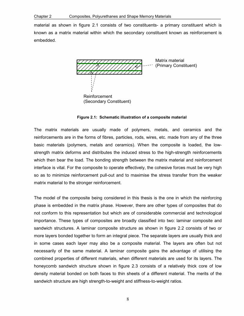
material as shown in figure 2.1 consists of two constituents- a primary constituent which is
known as a matrix material within which the secondary constituent known as reinforcement is
embedded.
Figure 2.1: Schematic illustration of a composite material
The matrix materials are usually made of polymers, metals, and ceramics and the
reinforcements are in the forms of fibres, particles, rods, wires, etc. made from any of the three
basic materials (polymers, metals and ceramics). When the composite is loaded, the low-
strength matrix deforms and distributes the induced stress to the high-strength reinforcements
which then bear the load. The bonding strength between the matrix material and reinforcement
interface is vital. For the composite to operate effectively, the cohesive forces must be very high
so as to minimize reinforcement pull-out and to maximise the stress transfer from the weaker
matrix material to the stronger reinforcement.
The model of the composite being considered in this thesis is the one in which the reinforcing
phase is embedded in the matrix phase. However, there are other types of composites that do
not conform to this representation but which are of considerable commercial and technological
importance. These types of composites are broadly classified into two: laminar composite and
sandwich structures. A laminar composite structure as shown in figure 2.2 consists of two or
more layers bonded together to form an integral piece. The separate layers are usually thick and
in some cases each layer may also be a composite material. The layers are often but not
necessarily of the same material. A laminar composite gains the advantage of utilising the
combined properties of different materials, when different materials are used for its layers. The
honeycomb sandwich structure shown in figure 2.3 consists of a relatively thick core of low
density material bonded on both faces to thin sheets of a different material. The merits of the
sandwich structure are high strength-to-weight and stiffness-to-weight ratios.
Reinforcement (Secondary Constituent)
Matrix material (Primary Constituent)

Chapter 2 Composites, Polyurethanes and Shape Memory Materials
9
Figure 2.2: Laminar Composite Structure
Figure 2.3: Honey Comb Sandwich Structure
2.2 Matrix material
The functions of a matrix material in a composite include the following:

Chapter 2 Composites, Polyurethanes and Shape Memory Materials
10
• To bind the reinforcements together.
• To transfer and distribute stresses to the reinforcement.
• To protect the reinforcement against physical damage as a result of mechanical
abrasion capable of forming cracks that may lead to failure at low tensile stress levels.
• To separate the reinforcement, and by virtue of its relative softness, prevent the
propagation of brittle cracks from reinforcement-to-reinforcement which could result in
catastrophic failures. In other words, the matrix material serves as a barrier to crack
propagation.
2.2.1 Polymer Matrix
Thermosetting resins which are high-molecular-weight plastics, such as unsaturated polyesters
and epoxies are the most widely used polymer matrices. They are used in large quantities in a
diversity of composite applications owing to the merits of low cost and good room-temperature
properties. However, they have the limitation of not being able to withstand high temperature.
Thermosetting resins determine the maximum service or operating temperature of the resulting
composites. They normally soften or degrade at much lower temperatures than that of the
reinforcements. The polymer matrix can also be thermoplastic resins, such as polyamides
(nylons), polycarbonate, polystyrene, and polyvinylchloride (PVC). High temperature
thermoplastic resins based composites are candidates for future aerospace and automotive
applications.
2.2.2 Metal Matrix
Metal matrices are usually ductile metal alloys of Aluminium, Magnesium, Titanium or Copper.
Some of their relative advantages over polymer matrices include elevated operating
temperatures, non-inflammable and greater resistance to degradation by organic fluids but they
are much more expensive than the polymer matrices and possess high strength-to-weight ratio.
Fibre materials are more commonly used as reinforcements. Metal-fibre composites have found
applications in the construction, automotive and aerospace industries.
2.2.3 Ceramic Matrix
Ceramics exhibit attractive properties of high stiffness, hardness, compressive strength, and
relatively low density. However they are plagued with limitations of low toughness and bulk
tensile strength, and a vulnerability to thermal cracking. Ceramic materials used as matrices
include Alumina (Al2O3), Boron Carbide (B4C), Boron Nitride (BN), Silicon Carbide (SiC), Silicon
Nitride (Si3N4), Titanium Carbide (TiC), and several types of glasses. Carbon fibres which can

Chapter 2 Composites, Polyurethanes and Shape Memory Materials
11
either be short or long are commonly used as reinforcements in ceramic composites. Current
applications of ceramic matrix composites are in metal-cutting tools and chemically corrosive
environments as well as areas in which operating conditions include elevated temperatures.
2.3 Background on Polyurethanes
Polyurethanes belong to the group of thermosetting polymers, but through variations in
chemistry, cross-linking, and processing, they also exist as elastomers and thermoplastic
polymers (Groover, 2002). Thermosetting polyurethanes with minimal cross-linking are
elastomers while those without cross linking are known as thermoplastic polyurethane. In the
classification of engineering materials, polyurethanes are known as plastic polymers. As a result
of many forms in which polyurethane may exist, it constitutes a unique material which possesses
properties that are not found in other materials. Consequently, it lends itself to designs in which
other materials are unsuitable.
Polyurethanes can easily be moulded into intricate geometries with usually no further processing
required. They are used in composite materials in engineering applications owing to their high
strength-to-weight ratio, cost effectiveness, low electrical and thermal conductivities, high
abrasion, and flexibility and corrosion resistance. Also, their curing process has no negative
impact on the properties of the reinforcing fibres. However, despite these attractive properties,
they are plagued with limitations of low strength and stiffness, and inability to withstand elevated
temperatures relative to metals. In addition, polyurethanes, unlike thermoplastic polymers, do
not lend themselves to recycling.
Elastomeric polyurethanes, in form of flexible foams are widely used as cushion materials for
furniture and automobile seats, and in mattresses. In rigid foams form, they are used for thermal
insulation of refrigerators, freezers and buildings. Un-foamed polyurethanes are highly elastic
materials. With cross-linking adjusted to achieve the desired properties for the appropriate
application, they can be moulded into varieties of products such as automotive body panels,
pallet truck tyres, escalator and heavy duty caster wheels, shoe soles, computer mouse pads,
bearings, flexible couplings, and car bumpers.
2.4 Reinforcements
Reinforcement is the stress bearing constituent of the composite and dictates the structural
integrity of the composite. The properties and thus the performance of the composites depend
on the quantity (concentration, volume fraction), size, shape, distribution and orientation of the
reinforcement. The mechanical properties of fibre reinforced composites in tension mainly
Chapter 2 Composites, Polyurethanes and Shape Memory Materials
12
depend on the strengths of the reinforcing fibres, the fibre volume fraction, the matrix strength
and the interfacial shear strength (Schulte & Fiedler, 1997). Reinforcements can be in the form
of glass and metal fibres, and shape memory materials.
2.4.1 Fibre Reinforcements
Fibre reinforcements are a class of materials that are either continuous filaments or discrete
elongated pieces, similar to lengths of thread. Man-made fibres have diverse applications. They
are used as a constituent of composite materials. They can be spun into filaments, thread,
string or rope. They can also be matted into sheets to make products such as paper or felt.
Fibres are often used in the manufacture of other materials. Glass and metal fibres are the
commonest man-made fibres. Fibreglass is made from extremely fine fibres of glass and silica.
Metallic fibres can be drawn from ductile metals such as copper, gold or silver and extruded or
deposited from more brittle ones such as nickel, aluminium or iron. Other materials used as
fibres are ceramics, polymers, carbon, and boron.
2.4.2 Fibreglass
Fibreglass diameters are usually in the range between 3 µ m and 5µ m and their merits include:
• Can easily be drawn into high-strength fibres from the molten state.
• Cheap and readily available.
• Relatively strong thereby ensuring a composite with improved strength.
• Possesses chemical inertness thus renders the resulting composite useful in a corrosive
environment.
Fibreglass based composites have found applications in automotive industries to reduce vehicle
weight and boost fuel efficiency. However, despite their high strengths they are flexible and
therefore not useful for structural applications (especially in bridges) where rigidity is a necessity.
Their applications are also limited to operating temperatures between 200o C to 300oC.
2.4.3 Carbon Fibre
The diameters of carbon fibres range between 3µ m and 5µ m. They are available both in
continuous and discrete forms. Carbon fibres are generally a combination of graphite and
amorphous carbon. They are usually coated with a protective epoxy to enhance adhesion with
the matrix material. Carbon fibres features include:
• High strength-to-weight and stiffness-to-weight.
• Retain their high strength-to-weight and stiffness-to-weight at elevated temperatures.

Chapter 2 Composites, Polyurethanes and Shape Memory Materials
13
• Resistance to moisture and wide range of solvents, acids and bases at room
temperatures,
• Exhibit a diversity of physical and mechanical characteristics, thus allowing carbon-
based composites to have specific engineered properties.
Carbon based composites have found applications in aerospace industries as aircraft structural
components.
2.4.4 Aramid Fibre
Aramid fibres are most frequently used with polymer matrices. The trade names for two of the
most common aramid fibres are Kevlar and Nomex. Some of the characteristics of aramid fibres
are as follows:
• Outstanding strength-to-weight ratios which are superior to metals.
• Good resistance to combustion.
• Stable up to relatively high temperature.
• Resistant to combustion as well as to creep and fatigue failures.
• Exceptional toughness and impact resistant.
Despite the remarkable features displayed by aramid fibres, they are susceptible to degradation
by strong acids and bases. Aramid based composites fibres have found applications in ballistic
products, pressure vessels and in automotive brake and clutch linings.
2.4.5 Other Fibre Reinforcements
Boron: Boron has a very high elastic modulus but its application to aerospace components in
which its property would have been an advantage, are limited by high cost.
Ceramics: Silicon carbide and aluminium oxide are the main fibre materials among ceramics.
They have high elastic moduli and can be used to strengthen low density and low modulus
metals such as aluminium and magnesium.
Steel: Steel filaments, both continuous and discrete, are used as reinforcing fibres in plastics
2.5 Background on Shape Memory Materials
Shape memory materials are constituents of smart or intelligent structures. They possess
interesting and unusual properties which facilitate their capability to return mechanically induced
strains upon heating or application of stress or electric field. They have the unique capability of
changing their physical properties such as stiffness, damping ratio, and viscosity, in response to

Chapter 2 Composites, Polyurethanes and Shape Memory Materials
14
the external stimuli (Lee & Lee, 2000). When integrated into structural components, they perform
sensing, diagnosing, actuating and repair functions thereby preserving structural integrity as well
as improved structural performance (Zhang, Ni, Natsuki & Iwamoto, 2007). A shape memory
material itself is not smart but can be used as a structural component to accomplish a desired
design function. Smartness refers to the exploitation of material properties to better serve a
design function than would be possible through conventional structural design (Srinivason &
McFarland, 2001; Hurlebaus & Gaul, 2006).
Smart structures respond to environmental changes at the most optimum conditions and
manifest their own functions according to the changes. They respond in a pre-determined
manner and extent in an appropriate time to an environmental stimulus such as temperature
variation or application of stress, and then revert to their original states as soon as the stimulus
is removed. Spillman, Sirkis & Gardiner (1996) defined a smart structure as a non-biological
structure that has the following attributes:
• A definite purpose.
• A means and imperative of achieving that purpose.
• A biological pattern of functioning.
The major advantage of SMAs over other shape memory materials is their high power to volume
ratio and large maximum strain recovery. SMAs are characterized by two unusual phenomena of
pseudoelastic effect and the shape memory effect (Yi & Gao, 2003). SMAs are candidate
materials for the actuators of smart structures since they have the ability to change properties of
their host matrices and are able to function in a controlled response to a change in environment
or operating conditions. However, despite their high potential for applications in diverse fields,
the need to heat up the SMA for activation, and the relatively slow response (since heat transfer
controls the kinetics) and low working efficiency, constitute drawbacks (Balta, Bosia Michaud,
Dunkel, Botsis & Manson, 2005). A detailed discussion of SMAs is presented in Chapters 3 and
4.

Chapter 3 Literature Review
15
CHAPTER THREE
LITERATURE REVIEW
3.1 History of Shape Memory Alloys
The understanding of SMAs started relatively late as compared to traditional engineering
materials such as metals and concrete. The first reported SMA behaviour is the pseudoelastic
behaviour of the Gold-Cadmium (AuCd) SMA that was observed in 1932 by Chang and Read
(Song, Ma & Li, 2006). These unusual properties exhibited by SMAs were also observed by
Arne Olander in 1938 (www.cs.uaberta.ca, March, 2006) but it was in the 1960’s that serious
research into SMAs advanced (Srinivasan & McFarland, 2002). The SMA behaviour was later
found in many other alloys such as Cu-Zn, Cu-Zn-Al, Cu-Zn-Sn, Ni-Al and Fe-Pt. Beuchler and
co-researchers at Naval Ordinance Laboratory, USA, also discovered these unusual properties
in nickel-titanium in 1963 (Song et al, 2006) and since then the understanding and the use of the
SMA has been flourishing. The acronym Nitinol for nickel-titanium SMA was derived from Nickel,
Titanium, and Naval Ordnance Laboratory. Since the discovery of SMAs, both in-depth research
and practical applications of SMAs have emerged and a great deal of effort is being expended to
characterize the property of the SMAs for the purposes of exploiting them.
3.2 General Properties of Shape Memory Alloys (SMAs)
SMAs have been defined by several authors and researchers but all the various definitions point
to the unique properties associated with SMAs. Yang (2000) defined SMA as a metal alloy which
can remember and revert to a specific shape after considerable deformation. Patoor et al, (2006)
defined SMAs as metallic alloys that can undergo martensitic phase transformations as a result
of applied thermomechanical loads and are capable of recovering permanent strains when
heated above a certain transformation temperature. SMAs are defined by their remarkable ability
to sustain and then recover large pseudoelastic strains by stress and temperature dependent
crystallographic transformations (Armstrong & Lilholt, 2000). SMAs possess sensing and
actuating functions and have the potential to control the mechanical properties and responses of
their hosts due to their inherent unique characteristics of SME and pseudoelasticity (Zhang et al,
2007). When integrated into structural components, SMAs perform sensing, diagnosing,
actuating and repair or healing functions, thereby enhancing improved performance
characteristics of their hosts (Ni, Zhang, Natsuki & Iwamoto, 2007).

Chapter 3 Literature Review
16
SMAs form a group of metals that have interesting shape-recovery characteristics when heated.
The SMA response is largely dependent on temperature owing to generation of latent heat. The
faster the rate of loading the less the time for the heat dissipation causing higher transformation
stress levels (Qidwai & Lagoudas, 2000). During the course of the shape recovery, the SMAs
produce a combination of both force and displacement. The amount of force and displacement is
dependent on the exact geometry of the SMA and the amount of heating (Gabriel, Trimmer &
Walker, 1988). To effectively use the recovery force generated by SMA wires, the amount of
current supplied to heat up the SMA wires must be controlled on the basis of the temperature on
the surface of the embedded SMA wires. Umezaki (2006) experimentally and numerically
studied the temperature distributions of NiTi SMA wires embedded in epoxy resin plates and
heated by supplying electric current. He reported that the temperature of the SMA wire surface
embedded in the plates depends on the length between SMA wires and the plate thickness, and
was less than that in the air.
The two unique properties of SMAs resulting from reversible phase transformations are the
thermal induced SME and the stress induced pseudoelasticity. Generally, SMAs exists in two
crystal phases and due to their different crystallographic structures, the two phases have
different elastic modulus. The stronger austenite or parent phase which is stable at high
temperature is named after an English metallurgist, William Chandler Austen and the softer
martensite or product phase which is stable at low temperature is named after the German
metallographer, Adolf Martens (Srinivisan & McFarland, 2002; Song et al, 2006). However, in
equiatomic NiTi SMAs there is a transition phase known as R-phase which is a function of heat
treatment temperature, thermal and mechanical cycles (Turner, 2001; Uchil, Kumara & Mahesh,
2002). The SMA in its martensitic phase can be easily deformed owing to its softness (Song et
al, 2006). Martensite and austenite solid phases differ in microstructures, Young modulus,
thermal expansion coefficient, and electrical conductivity (Azar, Sutapun & Huff, 1999). The
austenite phase has a well ordered body-centred-cubic (bcc) structure (appendix A) that
presents only one variant. Martensite phase has a lower symmetry which is simple cubic
structure (appendix A) and may exist in a multiple of variants depending on the type of phase
transformation. Therefore, while there are several ways by which martensite can be formed out
of austenite, there is only one route by which the martensite formed, will revert to austenite
(Lexcellent, Leclercq, Gabry & Bourbon, 2000).
NiTi SMAs exhibit a recoverable, repeatable, and rapid change in crystalline structure with
temperature cycling between the martensite and austenite phases. They are readily available in
various forms such wires or fibres, ribbons, bars, particles and porous bulks (Wei et al, 1998).

Chapter 3 Literature Review
17
NiTi SMAs in their lower temperature crystalline form can absorb some plastic deformation that
is recoverable in the higher temperature and the force required to deform it is much less than the
force that it can exert when heated (Pemble & Towe, 1999). NiTi SMAs have gained popularity
in medical devices because of their biocompatibility, fatigue resistance, and body-temperature
super-elasticity. The effectiveness of the SMAs depends on their configuration among other
parameters.
Qidwai and DeGiorgi (2004) investigated the phase transformation behaviours in hybrid SMA
composites under moderate compressive dynamic loads. Based on the parametric study carried
out on the volume fraction of pores and epoxy material for both hybrid epoxy-SMA composite
and plain porous SMA, they found that porous SMA and hybrid epoxy-SMA composites have
different behaviours. They reported that for porous SMA, the effective critical stresses decrease
and exhibit softened behaviour with increasing pore volume fraction owing to smaller effective
elastic modulus and cross-sectional area while for hybrid epoxy-SMA composite, increasing in
epoxy volume fraction and hence larger effective elastic modulus results in a considerable
increase in the hardening behaviour and critical stresses.
3.3 Characteristics of the Martensitic Transformation in SMAs
The behaviour of SMAs is more complex than that of common materials, but this complexity
forms the basis for their use in numerous applications. Different effects are observed according
to the thermomechanical loading path and the loading history of the material. However, the two
distinctive effects in the SMAs associated with the martensitic transformations are SME and
pseudoelasticity.
In SMA materials, the martensitic phase transformation is a reversible, crystallographic
reorientation and rate independent process between the two stable austenite and martensite
phases. The forward martensitic transformation (austenite-to-martensite) occurs when the free
energy of martensite becomes less than the free energy of austenite at temperature below a
critical temperature CT at which the free energies of the two phases are the same. Nevertheless,
the transformation does not exactly begin at CT but, in the absence of stress, the transformation
occurs at a temperature SM which is less than CT (Patoor et al, 2006). The transformation
continues to evolve as the temperature is lowered until a temperature fM is attained. In the
absence of stress, the reverse transformation (martensite-to-austenite) begins when the SMA is
heated from the martensitic phase at a temperature SA , higher than CT .

Chapter 3 Literature Review
18
Figure 3.1: Illustration of martensitic reverse transformations
(Adapted from Liang and Rogers, 1991: 38)
The transformation continues until a temperature fA is attained and the SMA material is in the
austenite phase. The equilibrium temperature CT is approximately given by: (Tong & Wayman,
1974)
2
fS
C
AMT
+= (3.1)
The martensitic transformation is schematically illustrated in figure 3.1. In general, there are four
important characteristic transformation temperatures for an SMA (Turner, 2001; Song et al,
2006; Patoor et al, 2006; Thompson and Loughlan, 2001). These critical temperatures at which
transformations take place are identified as SfS AMM ,, and fA , which represent the
temperatures at the start of martensite, finish of martensite, start of austenite and finish of
austenite transformations. In addition to these four critical temperatures, the differences
fS MM − and Sf AA − are important factors in the characterization of shape memory behaviour
(Patoor et al, 2006).
Efficient utilization of the recovery phenomenon requires the knowledge of the aforementioned
temperatures. However, for activation purposes, the most important of the transformation
temperatures is the austenite finish temperature fA . Thompson and Loughlan (2001) confirmed

Chapter 3 Literature Review
19
that transformation temperatures are highly dependent on alloy composition and level of
imposed stresses. For instance, a slight increase in the Ni content (0.2%) of NiTi SMA will
considerably lower the characteristic phase transformation temperatures ( fA for NiTi SMA with
a nominal composition of 49.8-50.0 % Ni is 67oC whereas for a composition of 50.0-50.2 % Ni
fA is 29oC). Besides the alloy composition, micro-structural defects, degree of order in the
parent phase, and the grain size of the austenite phase can also alter the transformation
temperatures by several degrees.
During the phase transformation processes, SMA exists in one or a combination of the
followings: the austenite phase, R-phase, self-accommodating (twinned) martensite phase and
the oriented (detwinned) martensite phase. The martensite phase may have two possible
origins: the self accommodating phase, from the transformation of austenite due to temperature
changes (in which there is no macroscopic shape change or phase transition strain), and the
oriented phase, accompanied with macroscopic shape change, resulting from application of
stress (mechanical loading) to the austenite phase and or the self-accommodating phase. The
martensitic variants are all crystallographically and energetically equivalent, they differ only in
orientation (Loughlan, Thompson & Smith, 2002).
Turner (2001) reported that SMA shows no macroscopic deformation during the martensitic
transformation and that because the product martensitic phase is of a lower symmetry than the
parent austenic phase, the crystalline structure change in the forward transformation produces
several martensite variants that are self accommodating (twinned martensite) so that no
macroscopic deformation results. When stress is applied to the twinned martensite, the variant in
the direction of the applied stress grows at the expense of other variant. In other words, a
detwinned martensite is formed upon application of stress. The accompanying shape change
from detwinned martensite to twinned martensite is discussed in section 3.4.1. The crystalline
change to austenite is however unique. Inducing the crystallographically unique reverse
transformation causes a strain recovery and the material reverts to its initial configuration. This
sequence forms the basis for the SME.
3.4 Shape Memory Effect
SME (one-way or two-way) is a phenomenon in which the SMAs having being considerably
deformed revert to their original configuration after being heated above a certain transition
temperature. SME, illustrated in figure 3.2 is based on the reversible martensitic transformation

Chapter 3 Literature Review
20
of the SMA between the highly symmetric austenite and the less symmetric martensite
(Appendix A) due to the application of heat or stress (Tsoi, Stalmans & Schrooten, 2002).
Figure 3.2: Schematic illustration of the shape memory effect
(Adapted from Duerig and Wayman, 1990)
3.4.1 One-Way Shape Memory Effect
One-way SME which is also known as pseudoplasticity, is a phenomenon in which the SMA
undergoes plastic deformation and then reverts to its un-deformed shape when heated above
the transition temperature.
Schematically shown in figure 3.3, the one-way SME begins from the high symmetry austenitic
phase. In the stress-free state, the SMA in its austenite phase is cooled below fM to form
twinned martensite. Upon the application of stress, detwinned martensite is formed. When the
Austenite phase
Twinned martensite
Detwinned martensite
Deform Cool Heat
fAT > fMT < fMT < fMT <
Figure 3.3: Schematic illustration of one-way shape memory effect
Cool
fAT >
Austenite phase
Twinned martensite

Chapter 3 Literature Review
21
detwinned martensite is heated above fA , it returns to the austenite phase and its original
shape. In NiTi SMAs, a strain of up to 9% can be completely recovered (free recovery) and a
recovery stress between 500 MPa and 900 MPa can be generated (constrained recovery) during
this process (Cho & Kim, 2005). There is however a critical stress, above which permanent
damage is caused to SME. This critical stress which is lower than the true yield stress of the
SMA defines the upper limit to which the SMA can be safely loaded without inducing damage to
the SME.
One-way SME is a once-off phenomenon, hence proper thermo-mechanical treatment is
required to obtain a complete cycle and care needs to be taken neither to overload nor overheat
the SMA in order to prevent degradation in the SME.
3.4.2 Two-Way Shape memory Effect
The two-way shape memory effect (TWSME) associated with forward and reverse martensitic
transformations is a phenomenon in which a reversible and spontaneous shape change during
heating and cooling occurs without external stress. TWSME is schematically illustrated in figure
3.4. In this case the SMA in its original shape is severely deformed at a temperature below fM
and when heated to above fA , the SMA reverts to its original shape and upon subsequent
cooling to below fM it returns to the deformed shape.
TWSME can be produced by several training methods which include over-deformation, shape
memory (SM) training, superelastic training, thermomechanical training and ageing under
external stress. Training is a thermomechanical treatment in which the SMAs are conditioned to
remember a predetermined geometrical shape at high temperature greater than fA and another
Cool Deform
Cool
Heat
fAT > fMT < fMT < fAT >
Figure 3.4: Schematic illustration of the two-way shape memory effect
Austenite phase
Twinned martensite
Detwinned martensite
Austenite phase

Chapter 3 Literature Review
22
shape at low temperature lower than fM (Lexcellent et al, 2000). TWSME by shape memory
training involves carrying out shape memory cycles repeatedly until the two-way behaviour
begins. The first shape memory cycle is the cooling of the SMA to below fM and followed by
deformation. Upon heating, the SMA reverts to the undeformed shape. When this process is
repeated for between 10-15 times, the SMA will begin to change shape upon cooling, moving in
the direction in which it was consistently deformed during the training cycles.
TWSME produced by over-deformation is considered as a preferential creation of certain
variants of martensite that are energetically more stable. In this case, the SMA in its martensitic
phase is considerably deformed by mechanical loading. This deformation induces the creation of
defects and dislocations that stabilize the SMA in this configuration. When heated to the
austenite phase, the SMA transforms but as a result of the excessive deformation the
dislocations and defects still remain. In other words, the SMA will not completely recover its
deformed shape. When the SMA is subsequently cooled to the martensite state, the SMA will
revert to the over-deformed state in order that the internal stresses due to the dislocations are
accommodated.
Wang, Omori, Sutou, Kainuma and Ishida, (2005) reported that tensile, compressive and cold-
rolling deformations can be utilized to induce the TWSME. Lexcellent et al (2000) reported that
although thermomechanical cycling is quite essential for the completion of the training of the
SMA, but this process produces undesirable effects such as elevation of the transformation
temperatures, widening of the hysteresis loop, and an increase in the levels of residual strains.
3.4.3 Comparison of One-Way and Two-Way Shape Memory Effects
As the name implies, only one shape (in the austenite phase) is memorised in the one-way SME
whereas, two-way SME refers to the memorisation of two shapes (one shape in the austenite
phase and the other in the martensite phase). In one-way SME, the SMA must be re-deformed
to repeat the SME after the completion of individual cycles of deformation and heating whereas
in TWSME only temperature is required to be varied to effect the change in shape. Stalmans
(2006) reported that the two-way SME has a smaller strain range than the one-way SME and is
in general limited to below 3%.
3.5 Pseudoelasticity
Pseudoelasticity which is also known as superelasticity is the ability of the NiTi SMA to return to
its original shape upon unloading after substantial deformation (Nasser & Guo, 2006). This

Chapter 3 Literature Review
23
functional property of NiTi SMAs takes place at almost a constant temperature as shown in
figure 3.5. The phase(s) at which the SMA exist(s) during the loading process (path PQR) and
the unloading process (path LMN) are found in appendix B.
Figure 3.5: Schematic illustration of the pseudo-elastic effect
Figure 3.6: Schematic representation of superelasticity (Adapted from Duerig and Zadno, 1990)
Under most general conditions, pseudoelastic thermomechanical loading paths start at zero
stress in the austenitic region, then move to the detwinned martensite region and then unload
fM sM SA fA
Temperature
Load
Elastic Energy
Strain
Str
ess
austenite martensite
austenite martensite
P
R
Q
L
M
N

Chapter 3 Literature Review
24
again to the starting point. The pseudoelasticity refers to the observed non-linear unloading
characteristics while superelasticity is associated with the stress plateau and an inflection point
upon unloading shown in figure 3.6. Unlike SME in which martensite is formed when the SMA
is cooled to below SM , pseudoelasticity occurs when the SMA is completely composed of the
austenitic phase. Under the application of stress, the austenite is transformed to martensite and
upon the removal of the stress the martensite reverts to austenite. The martensite formed via
this transformation process is known as the stress induced martensite (SIM). It suffices to say
that during the phase transformation, the NiTi SMA exist as a mixture of austenite and
martensite (Appendix B).
3.6 Damping Properties of Shape Memory Alloys
The damping capacity which depicts the dissipation of mechanical energy into heat is not a
characteristic behaviour that is specific to SMAs only. All materials exhibit this property.
However, SMAs have been found to exhibit a damping capacity that is far greater than that of
other materials (Patoor et al, 2006). SMAs excellent damping properties result from the
existence of numerous interfaces related to the martensitic transformation. These interfaces are
those between austenite and martensite, those between the different variants of martensite, and
the twin boundaries inside the martensite itself. With material initially in the austenitic phase,
there are three damping regimes that are distinguishable in SMAs, these are:
• For operating temperatures higher than S
M and weak excitation, the SMA remains in
the austenitic phase. The damping capacity for this regime is small.
• For operating temperatures below fM , the damping capacity increases owing to the
large number of interfaces present in the material in the martensitic phase.
• For operating temperatures above SA and stress levels high enough to induce stress
induced martensite, the damping capacity reaches its maximum value. During the
loading cycles, creation and displacement of austenite-martensite interfaces are
accompanied by a strong level of defects and large thermomechanical coupling.
The use of SMAs for passive control of structures relies on their damping capacity, which
represents their ability to dissipate the vibration energy of structures subject to dynamic loading.
This damping capacity comes from two mechanisms: martensite variation’s reorientation which
exhibits SME and stress-induced martensitic transformation of the austenite phase which
exhibits the superelasticity. Amongst all SMAs, Cu-Zn-Al SMA has the best damping properties
due to the martensite interface movements. Piedboeuf, Gauvin and Thomas (1998) investigated

Chapter 3 Literature Review
25
the passive damping characteristics of SMA reinforced polymer matrix composites and reported
that the influence of ambient temperature on the damping capacity of the superelastic NiTi wires
can be negligible. They also established that an increased superelastic effect can be achieved
by 0.2% chrome-doping of the NiTi wires.
Liu, Xie and Humbeeck (1999) investigated the damping characteristics of NiTi based SMAs with
respect to the effect of strain amplitude and strain rate. They reported that the damping capacity
of a deformed martensite NiTi SMA bar under tension–compression cycles increases with
increasing strain amplitude and strain rate, but decreases with loading cycles and then reaches
a stable minimum value. They also confirmed that when the NiTi SMA was cyclically loaded, the
maximum stresses increased with increasing cycles but with further cycling, the rate of increase
slowed down. Dolce and Cardone (2001) investigated the superelastic NiTi SMA wires subjected
to tension loading. They reported that the damping capacity depends on temperature, loading
frequency and the number of loading cycles. They found that the mechanical behaviour of the
wires is stable within a useful range for seismic applications. Also, they suggested that the
austenite wires should be prestrained for increased effectiveness of energy dissipation.
Gandhi and Wolons (1999) utilized a complex modulus approach to characterize the damping
capacity of superelastic SMA wires for convenient integration with structure dynamics. Their
study showed that a superelastic SMA wire demonstrates the damping capacity not only under
tension loading, but also under cyclic bending. As large cross-section-area SMAs become
available, studies on the properties of SMA bars or rods have attracted more attention.
Dolce and Cardone (2001) compared the martensite damping and austenite damping of NiTi
SMA bars subjected to torsion. They found that the damping capacity of the martensite NiTi bar
is quite a bit better than that of the austenite NiTi bar, although the prior cannot remain at its
highest value as the residual strain accumulates. They also noticed that the martensite bar’s
mechanical behaviour is independent of loading frequency and that of the austenite bar slightly
dependent on the frequency. This implies that both martensite and austenite NiTi SMA bars can
work in a wide frequency range and have a good potential for seismic protection (Song et al,
2006).
3.7 Interfacial Properties of SMA based Composites
The stress transfer between the matrix material and the reinforcement occurs primarily through
interfacial shear, and it occurs around the periphery of the reinforcement. Thus, the strength and
hence the performance of reinforced composites depends on the interfacial bond strength
Chapter 3 Literature Review
26
between the matrix phase and the reinforcement phase. Consequently, the importance of the
understanding of the interfacial bonding behaviour and stress transfer properties between the
embedded SMA wires and polymeric hosts cannot be overemphasized (Hu and Wang, 2005).
The interfacial properties are particularly significant for applications in which the recovery stress
generated by the SMA is an important factor, since the recovery stress is directly related to how
much stress that can be transferred from the SMA wires to the composite without debonding.
When the embedded pre-strained SMA wires are activated, large interfacial shear stresses will
be generated at the SMA/matrix interface. The stronger the interface, the greater is the transfer
of induced stress. The shear strength of this interface must therefore be stronger than the
recovery stresses of the SMA associated with the activation. If otherwise, the interface will fail
and the objective of integrating the SMA will be defeated.
It therefore suffices to mention that before embedding SMA wires into polymeric hosts, it is
essential that the interfacial properties between the two constituents be investigated in order to
obtain the strongest bond possible. With suitable surface preparation of the SMAs, the interfacial
bond strength will be increased, therefore, the occurrence of interfacial de-bond may be
substantially reduced. Thompson and Loughlan (2001) reported that although abrasive action
degrades the recovery force due to the formation of lattice defects, such as dislocations but
however, sandblasting the SMA to providing an abraded surface enhances the mechanical
interaction between the SMA and the matrix material and, therefore, hinders interfacial de-bond
upon activation.
Paine and Rogers (1993) investigated the effect of surface treatment on SMA wires before
embedment into a polymer matrix. They reported that SMA wires treated by sandblasting
produced a better bond than untreated ones. The bond strength of the treated wire is up to
217% greater than the untreated wires.
Among the various mechanical interface testing techniques, the reinforcement pull-out test, is
the easiest, most popular and satisfactory test method. Lau et al (2005) experimentally studied
the wire pull-out properties of prestrained SMA wires embedded in polymer composites when
the resulting hybrid matrices were subjected to different temperatures. They reported that an
increase in the externally applied current which changes the phase condition in the wires, leads
to a corresponding increase in the debonding stress, which initiates complete debonding at the
bond interface between the SMA wires and polymeric hosts.

Chapter 3 Literature Review
27
3.8 Improvement of the Properties of NiTi Shape Memory Alloys
The ability of actuating materials to operate within the host matrix is, amongst others, dependent
on the integrity of the actuating materials. It is therefore essential that prior to integrating SMA
actuators with the host matrices, the effect of SMA preparation and composite manufacturing, on
the shape memory performance and how to improve on this performance must be ascertained.
In order to determine the true usability of the actuators, the repeatable range of recovery stress
that can be generated needs to be assessed. One of the ways in which this can be achieved is
by cycling SMAs through their transformation temperature range and monitoring the associated
recovery stress. Despite the excellent thermomechanical and thermoelectrical properties
possessed by NiTi SMAs, research has been conducted on how to improve on their
performance characteristics. The superelastic behaviour of SMAs can be improved by increasing
the austenitic strength, decreasing the stress rate, decreasing the hysteresis and eliminating the
R-phase transition (Thompson & Loughlan 2001). This could be achieved by cold working,
ageing, and varying the composition of the alloys.
Duerig, Melton, Stockel and Wayman (1990) reported that by decreasing the annealing
temperature, the amount of cold work in the SMAs is increased, leading to an increase in the
austenitic strength. This process also resulted in a decreased stress rate, decreased permanent
residual strain and an increase in stiffness. The SM is decreased and the superelasticity
temperature window shifts to lower temperatures. However, the shortcoming of this process is
that the ductility of the SMAs decreases. This limitation can be overcome when the annealing is
done at a reduced duration and at an elevated temperature. Short annealing times at high
temperature produce high strength superelastic alloys without shifting the SM and get rid of the
R-phase transformation, thereby improving the superelasticity.
Cui, Li and Zheng (2006) studied the martensitic transformation characteristics and the
associated thermal expansion behaviours of NiTi SMAs after severe cold deformation. They
reported that cold deformations higher than the recoverable limit results in massive dislocations
and complex martensite morphologies in the NiTi alloy. They found that the density of
dislocations can be managed by controlling the ratio of the cold deformation. Consequently, the
thermal-mechanical behaviours of the NiTi alloy can be tailored due to the interactions between
the martensite variants and dislocation texture. By proper design of the surface curve, domains
with different dislocation density can be introduced into the bulk body of the alloy, and a
repeatable strong contraction overlaps the behaviours of the normal cold rolled sheets. They
established that due to the interactions between the deformation structure and martensite

Chapter 3 Literature Review
28
variants, the reverse transformation temperature range was significantly enlarged. They reported
that one of the possible applications of their findings is the so called temperature memory effect
in which SMAs will not necessarily be embedded into composites but rather a curved surface
NiTi alloy would be cold rolled to above its recoverable limit.
Lu, Zhao and Cai (2005) investigated the damping behaviour of NiTi based alloys using dynamic
mechanical analyser instruments. They confirmed that appropriate cold-rolling deformation on
the martensite of equiatomic NiTi SMA enhances its damping capacity due to the dislocations
introduced by the cold-rolling deformation. They also confirmed that ageing treatment for a near
equiatomic NiTi alloy (50.8% Ti) can increase the damping capacity during phase
transformation. Mukhawana and Philander (2006) reported that thermomechanical cycling and
ageing erases the non-homogeneous transformation and inconsistent yield strength of NiTi
SMAs.
Uchil et al (2002) established that heat treatment of NiTi SMAs at high temperature stabilises R
–phase transformation and that the number of critical cycles needed for the stabilisation
increases with increasing heat treatment temperature which tends to be constant above 520 oC.
Vokoun et al (2003) studied the recovery stresses generated by NiTi shape memory wires under
different constraint conditions. They reported that training stabilizes the behaviour of shape
memory wires and that for a given strain; the recovery stresses increases with increases in
temperature while cooling results in decreasing recovery stresses. They also reported that the
rate of change of stress with respect to temperature generally increases substantially with
increasing pre-strain.
Bhaumik, Ramaiah and Saikrishna (2006) investigated the effects of thermomechanical cycling
on the strain response of NiTiCu SMA wire actuator. They established that the strain response of
SMA actuators can be stabilized through thermomechanical cycling at a higher stress than the
application stress and that pre-straining the SMAs increased the transformation temperatures.
They also established that due to the decrease in the mass fraction of the material involved in
the transformation and the increase in non-chemical opposing energy, thermomechanical cycling
reduced the transformation temperature and widened the temperature range over which the
transformation took place. They reported that the decrease in the transformation mass fraction
and the increase in non-chemical opposing energy are ascribed to the stabilization of
martensite/austenite phase.

Chapter 3 Literature Review
29
3.9 Shape Memory Alloys based Composites
Composite materials are increasingly being used for primary load bearing components in
aerospace applications and there are strong demands for materials that have high mechanical
properties of stiffness, yield stress, fracture toughness, etc especially in the high temperature
region. Integration of shape memory materials into conventional composites will yield intelligent
materials that would exhibit features that satisfy these demands as well as creating safer
environment (Shimamoto et al 2004). In the last decade, the development of smart composite
materials and structures has become an attractive research topic in an area of materials science
and engineering.
The high specific stiffness and strength characteristic advantages of composites over other
engineering materials have increased their applications in various engineering structures (Lee &
Lee, 2000). These characteristic advantages of composites can be improved upon by the
integration of SMAs which provides functions such as sensing, actuation and information
processing essential for monitoring, self-adapting and healing of structures. The resulting SMA-
based composites exhibit unique properties or functions such as self-strengthening, active
modal modification, high damping, damage resistance and shape control that make them to be
useful in many engineering applications (Zhang et al, 2007).
Bruck and Moore (2006) investigated the relationship between the mechanical response of SMA
wire-reinforced fibreglass composites and the composition of SMA wire reinforcement. Based on
the tensile tests performed on dog-bone fibreglass composite specimens, they reported that
SMA wire-reinforced fibreglass composites exhibit greater ductility than either of the constituents
of the composites and that an increase in the volume fraction of the SMA wire reinforcement
increases the strength and ductility of the SMA wire-reinforced fibreglass composites. Davoodi,
Noori, Hou and Marioni (1997) studied the effect of temperature on SME and damping of NiTi
SMAs. They established that NiTi SMAs could be used to shift the natural frequency of a
structure away from its exciting frequency and as such control the amplitude of the structure’s
motion during vibration. Aboudi (1997) implemented a micro structural model that couples the
local (micro) and global (macro) effects to analyze the behaviour of metal matrix and resin matrix
composites materials embedded with SMA fibres. His results, although restricted to the normal
stress-strain behaviour, showed that the presence of SMA fibres modify the response of the
system.
Yang (2000) established that despite the good mechanical properties of SMAs, their application
is limited by low speed response and hence a long cycle lifetime. However, by coupling NiTi

Chapter 3 Literature Review
30
SMAs with ferroelectric ceramics, which are very sensitive to applied stresses through the
piezoelectric effect and have fast response times but with small displacements due to small
strain magnitude, composite materials can sense and actuate to dampen structural vibration
without the use of an external control. Lau (2002) investigated the dynamic behaviour of
clamped composite beams embedded with shape memory alloy wires. He established that the
natural frequency and damping properties of composite structures could be actively controlled by
embedding prestrained shape memory alloy wires.
The actual design for enhancing the mechanical properties of the SMA base composites is
schematically depicted in figure 3.7.
Figure 3.7: Basic design concept for a smart composite material
3.10 Application of NiTi SMAs embedded in Polymeric Composites
Amongst the commercially available SMAs, NiTi alloys are the most widely used because of
their good mechanical properties and material characteristics of shape memory performance
Shape Memory Heat Treatment
Pre-strain
Tension
2
ε
Heating above fA
SME → Fibre Shrinkage
Austenite Phase
Martensite Phase
Martensite Phase
Austenite Phase
NiTi SMA
Polymeric host
2
ε

Chapter 3 Literature Review
31
attributable to large recovery of strain, good processibility, fatigue resistance, wear resistance,
good corrosion resistance, cyclic stability, high power density, solid state actuation capability,
durability, high damping capacity, and biocompatibility which enable them to be used in the
biomedical field (Wei et al, 1998; Qidwai & Lagoudas, 2000). NiTi SMAs have found many
applications in different fields of engineering and science as a result of their good
thermomechanical and thermoelectrical characteristics. The extensive use of NiTi SMAs as
active or smart element in various composites is due to the ease of fabricating them into various
forms such as wires, ribbons, bars, particles and porous bulks. Considerable amount of work
has been done in the area of embedding SMAs into composite structures. The main objective
behind these works have been to obtain a better understanding of the effects that embedded
SMAs have on the material properties and behaviour of composite structures.
Research has been carried out into combining SMA fibres with composites to produce reinforced
composite matrices. These hybridized composite materials have the ability to alter their stiffness
properties among others when the SMAs are activated. The hybridized composites can also be
utilized for shape control as well as for various vibration controls due to the excellent damping
properties of the SMAs. Song et al (2006) reviewed the basic properties of NiTi SMAs and their
applications in passive, semi-active and active control of civil structures. They reported that
strong hysteretic effects in the stress-strain curves for loading and unloading cycles and hence
the energy being dissipated during these cycles, for both martensite and superelastic SMAs
provide the basis for developing passive structural damping devices using both martensite and
super elastic SMAs. They also reported that the SME enables martensite NiTi to be used as
actuators and also enables their applications in active and semi-active controls of civil structures.
Liang and Rogers (1989) explored two different techniques by which SMAs embedded into
composite structures can be utilized. The two techniques are active property tuning (APT) and
active strain energy tuning (ASET). APT refers to the increase of the Young’s modulus, yield
strength and other properties of the SMA during the transformation of martensite phase to
austenite phase. These changes in material properties especially the Young’s modulus were
used to modify the dynamic characteristics of the composite plate in which the SMA wires had
been embedded. On the other hand, ASET involves the embedment of the pre-strained SMA
wires in martensitic phase into a composite material. Upon the application of heat, the SMA
wires are constrained from returning to their memorized length and thus creating the recovery
force. This recovery force is used to increase the strain energy and the stiffness of the structure
and thus improving structural problems such as shifting natural frequency, suppress vibration,

Chapter 3 Literature Review
32
increase critical and thermal buckling loads, control post-buckling and thermal post-buckling
deflections and prevent cracks and fatigues.
If the SMA wires are located eccentrically with respect to the neutral axis, the recovery force
generated by the SMA wires will produce a bending moment that can change the shapes or
positions of SMA/composite structures. This type of ASET is called the active shape control
(ASC). It should be noted that for each occurrence of the ASC and ASET the APT is always
there. It was found that the effect of APT is much smaller as compared to the effect of the other
two (Rogers, Liang & Jia, 1991). Research on the SMA structures especially beams are rather
extensive. Although the objective of all the researchers was to investigate the effect of SMA in
improving structural behaviour, but their experimental investigations differ in terms of structural
configuration, form of SMA, number of SMA training cycles conducted and the method of
analysis.
3.10.1 Vibration and Dynamic Response Control
Ni, Zhang, Masuda, Yamamura and Iwamoto (2006) investigated the vibration characteristics of
laminated composite plates with embedded shape memory alloys. The vibration mode of
unidirectional SMA wires clamped cantilevered composite plate was measured to investigate the
influence of both SMA arrangements and temperatures on vibration characteristic. The stiffness
tuning capability of the woven NiTi laminated plate was evaluated by impact vibration tests. They
found that the natural frequency of the SMA-based composite plate is a function of the volume
fraction of the SMA. At a temperature of about 100 oC when the SMA is in the austenite phase,
the natural frequency of the SMA-based composite plate is almost twice that of the laminated
plate without SMA implant. In the case of the woven SMA-based laminated plates, they reported
that the natural frequency increased at about 1.8 times when compared to laminated plate
without SMA implant. They established that the use of SMA wires and woven SMAs mesh is an
effective way of damping control in structures.
Kim, Park and Moon (2004) studied the vibration of thermally post-buckled composite plates
embedded with NiTi SMAs. They found that natural frequencies, thermal deflections and critical
temperatures are function of the volume fraction initial strain of the SMA fibres. They reported
that an increase in the volume fraction and initial strain of the NiTi SMA fibres results in a stiffer
plate and hence increases natural frequencies, lowers thermal deflections and raises critical
temperatures. They also reported that in the pre-buckled region, the presence of SMA in the
composite plate increases the natural frequency due to the recovery stress of the SMA.
However, in the post-buckled region, the natural frequencies of the SMA-embedded plates are

Chapter 3 Literature Review
33
lower than those without SMA. This is due to the increase in weight of the plate and a decrease
of the thermal deflection owing to the use of the SMA fibres. But nevertheless, they established
that SMA fibres can be used to control the vibration behaviour of composite structures due to
controllability of the natural frequencies, critical temperatures and thermal deflections.
Lau et al (2002) analytically and experimentally studied the natural frequencies of smart
composite beam structures clamped at both ends. Neglecting the effect of the curing
temperature of the matrix and the SMA’s temperature on the surrounding, the differential
equation obtained by combining the stress recovery equation of Brinson’s model (1993) and
lateral vibration equation of the beam was solved analytically to obtain the roots of the natural
frequency of the beams. The experimental results were in close agreement with the analytical
results. They found that at low volume fraction of SMA, the natural frequencies decreased
because of the thermal compressive stress that existed. However, as the volume fraction
increased, tension recovery stress surpassed the compressive stress and hence raised the
natural frequencies.
Turner (2000) investigated glass/epoxy composite laminates embedded with 5% prestrain NiTi
SMA actuators under thermal and acoustic loads for dynamic response abatement applications.
Also investigated were conventional composite laminates with and without additional composite
layers subjected to thermal and acoustic loads. He found that the optimal operating temperature
for dynamic response performance of hybrid composite laminates embedded with SMA
actuators depends on the matrix material, the SMA’s composition, volume fraction of the SMA
and level of pre-strain. He reported that as little as 13% volume fraction of SMA will completely
nullify thermal post buckling over a small temperature range and that embedding SMA actuators
into hybrid composite laminates is more effective in increasing the fundamental frequencies and
reducing the amplitude of dynamic response, when compared to stiffening the hybrid composite
laminates by adding additional composite layers. He established that a reduction in dynamic
response could be achieved by embedding SMA actuators into composite laminates.
Baz et al (1990) studied the feasibility of utilizing NiTi actuators in controlling the flexural
vibrations of a cantilevered beam. They confirmed that at the time of activation the actuator
shrinks and exerts a force which provides the restoring control movement. They established that
NiTi actuators are feasible for vibration control applications and can be extended to control
higher mode shapes via implementing sophisticated control strategies such as time-sharing
strategy.

Chapter 3 Literature Review
34
Gordaninejad, Ghazavi, Tabandeh and Ghomshei (2005) investigated the transient response of
a thick polycarbonate composite beam which had SMA reinforcements embedded along its
neutral axis. Under the influence of a harmonic force excitation exerted as a point load at its free
end, they reported that the vibration amplitude of the composite beam depends on temperature,
activation voltage, SMA layer thickness, beam length and the martensitic residual strain.
zero thickness
0.05 thick
0.4 thick
0.1 thick
0.2 thick
Time (s)
Lateral tip deflection (mm)
Figure 3.8: Effect of SMA layer thickness on beam response
(Adapted from Gordaninejad et al, 2005)
Zero residual strain
0.5% residual strain
1% residual strain
2% residual strain
4% residual strain
Time (s)
Figure 3.9: Effect of martensitic residual strain on beam response
(Adapted from Gordaninejad et al, 2005)
Lateral tip deflection (mm)

Chapter 3 Literature Review
35
They established that the thicker the SMA layers, the greater the reduction of vibration amplitude
and that a fractional increase in martensitic residual strain in the SMA results in a significant
reduction in the amplitude of vibration. Their results illustrated in figures 3.8 and 3.9, confirmed
that embedding thin SMA layers in the beam could be an effective way to controlling the beam
vibration.
Mei, Duan, Tawfik, Goek and Ro (2007) studied the vibration of rectangular graphite-epoxy
laminated composite plates with and without embedded NiTi SMA fibres at elevated
temperatures. They found that an increase in the volume fraction and pre-strain of the NiTi SMA
results in a stiffer plate.
Frequency (rad/s)
Frequency (rad/s)
Temperature (oF)
Temperature (oF)
Figure 3.11: Effect of 30% volume fraction and 3% prestrain of NiTi SMAs on natural frequency of a clamped-clamped plate
(Adapted from Mei et al, 2007)
Figure 3.10: Effect of 20% volume fraction and 3% prestrain of NiTi SMAs on natural frequency of a clamped-clamped plate
(Adapted from Mei et al, 2007)

Chapter 3 Literature Review
36
They also found that at a temperature less than the critical buckling temperature, the recovery
stress generated by the SMA overwhelms the stress due to thermal expansion. They reported
that the large recovery stress generated by the NiTi SMA increases the stiffness, the critical
buckling temperature and the natural frequency of the SMA embedded composite plate.
From figures 3.10 and 3.11, it can be seen that for the same level of pre-strain (3%) an increase
in the volume fraction of the SMA from 20% to 30% leads to an increase in the natural frequency
in the three vibration modes. And from figures 3.11 and 3.12 it can be seen that with the same
volume fraction of SMA (30%) an increase in the pre-strain from 3% to 5% increases the natural
frequency of the plate in the three vibration modes. From the foregoing, they established the
effectiveness of embedding SMA for frequency tuning and vibration control.
3.10.2 Stiffness and Impact Damage Control
Tsai and Chen (2002) studied the dynamic stability of NiTi SMA fibres reinforced composite
beam shown in figure 3.13, subjected to an axial periodic dynamic force. They confirmed that the
dynamic stability is a function of temperature, the volume fraction of the NiTi SMA fibres and the
pre-straining of the wires. They found that the natural frequencies of the composite beam
increase with increase in temperature. In other words the composite beam is more stable at high
temperature. They reported that an increase in the number of the NiTi SMA fibres as illustrated
Temperature (oF)
Frequency (rad/s)
Figure 3.12: Effect of 30% volume fraction and 5% prestrain of NiTi SMAs on natural frequency of a clamped-clamped plate
(Adapted from Mei et al, 2007)

Chapter 3 Literature Review
37
in figure 3.14 and increasing pre-strain as shown in figure 3.15, increases the stiffness of the
composite beam and hence an increase in the buckling strength. They established that the
presence of the NiTi SMA fibres increases the stiffness of the composite beam and hence a
more dynamically stable composite beam is obtained.
Simple-support
Fibre glass resin matrix
Sleeve
NiTi fibres
Figure 3.13: NiTi reinforced composite beam
(Adapted from Tsai and Chen, 2002)
15 wires
Temperature (oC)
Buckling strength
Figure 3.14: Effect of number of wires on buckling control
(Adapted from Tsai and Chen, 2002)
10 wires 5 wires

Chapter 3 Literature Review
38
Meo, Antonucci, Duclaux and Giordano (2005) investigated the impact damage behaviour of
carbon fibre/epoxy composite plates embedded with NiTi SMAs. They found that owing to the
superelastic and hysteresis behaviours of SMA wires, their use improved the strain energy
absorption capability of the composite plate, by increasing its overall bending and shear
elasticity, thus reducing ply failures. They also found that the closer the SMA wires are to the
impact location, the higher the effect of the SMA wires on the absorption of impact energy,
particularly on the contact deformation, the global bending deformation and the transverse shear
deformation. They confirmed that increasing the density of SMA wires significantly, reduces ply
failures of the composite plate. They established that for low velocity impact, embedding SMA
wires can be an effective way to increase the impact damage resistance of hybrid composite
structures when compared to conventional composite structures.
Armstrong and Lilholt (2000) investigated the time dependent, super-viscoelastic behaviour of
low density polyethylene matrix material embedded with NiTi fibre reinforcements when
subjected to an isothermal tensile cycle composed of a constant strain rate tensile loading
followed by a constant stress rate tensile unloading. They reported that the qualitative behaviour
of the SMA fiber reinforced composite was primarily dependent on the fibre mechanical
response. This is as a result of the SMA fibres possessing higher strength and stiffness than the
polymeric host. They established that NiTi fibre actuated viscoelastic low density polyethylene
Buckling strength
0.5% pre-strain
0.1% pre-strain
0.2% pre-strain
Temperature (oC)
Figure 3.15: Effect of pre-strain on buckling control
(Adapted from Tsai and Chen, 2002)

Chapter 3 Literature Review
39
matrix composite exhibited a large increase in strength, stiffness, and shape recovery energy in
comparison to the homogeneous polymer matrix.
Zhao and Zhang (2007) investigated the thermomechanical properties of a composite
asymmetrically embedded with a SMA layer under thermal and mechanical loadings. They found
that the beam deflection depends on the thickness of the SMA layer and the moment generated
by the SMA. They also found that whereas asymmetric embedding of a SMA layer results in
moment generation of the beam, the SMA embedded symmetrically produces no moment. They
confirmed that the more asymmetric the SMA layer, the more the bending. They established that
the thicker the SMA layer, the stiffer the composite beam and hence the smaller the composite
beam deflection.
Lau, Ling and Zhou (2004) theoretically and experimentally investigated the damage resistance
properties of SMA stitched glass/epoxy composites after low velocity impact. They reported that
the tensile modulus of the SMA stitched composite plates was higher than the unstitched
composite plates. They also reported that the number of translaminar cracks and delamination
energy were greater in the unstitched composite plates compared with the SMA stitched
composite plates. It was also reported that the SMA stitched composite plates have increased
damping ratio and rebounding energy compared to the unstitched composite plates. They
established that it is possible to use SMA wires to stitch and reinforce composite structures to
reduce damage due to low velocity impact.
Kim and Roh (2003) studied the adaptability of hybrid smart composite plate under low velocity
impact. The SMA fibres were embedded within the graphite/epoxy composite plate and
piezoelectric sensors were mounted on the opposite side of the impact. They found that the
deflection of the composite plate depends on temperature, volume fraction of the SMA fibres and
the orientation of the SMA fibres. They reported that at an elevated temperature, the elastic
modulus of the SMAs increases in its austenite phase and results in the stiffness increase of the
composite which thus reduces the deflection. They also reported that an increase in the SMA
fibre volume fraction decreases the dynamic impact induced deflection. They ascertained that
SMA fibres embedded within the layers of a composite beam can significantly enhance the
global resistance to low velocity impact of the composite beam.
Lee and Lee (2000) analysed the buckling and postbuckling behaviour of laminated composite
shells with embedded SMA wire actuators. They reported that under simply supported boundary
conditions, activated SMA wires embedded in the direction of buckling offered buckling

Chapter 3 Literature Review
40
resistance to composite shells subjected to external load while activated SMA wires embedded
in the opposite direction of buckling enhanced buckling. However, under clamped-clamped (CC)
boundary conditions activated SMA wires have no influence on buckling irrespective of the
direction of buckling at which they are embedded. Although SMA wires have no influence on the
buckling under CC boundary conditions, they however reduced the amplification of lateral
deflections. Regarding thermal load, they reported that the larger the number of embedded
SMAs the higher the critical buckling temperature and the smaller the postbuckling deformations.
They established that the integration of SMA wires reduced deflection and offer resistance to
buckling.
3.10.3 Shape and Position Control
Lee and Choi (1998) studied the shape control of a composite beam with embedded SMA wire
actuators. The SMA wire actuators were directly and eccentrically attached to the composite.
The flexible composite beam was investigated under the action of axial compressive loadings.
They found that the shape control of composite beams does not depend on thermal moment but
is dependent on initial geometric imperfection. They also found that the activation force
generated by the activated SMA wire actuators results in either an increased buckling load or
‘snap-through’ of the composite beam. They reported that the dominant and decisive factor
which influences the shape control of the composite beam is the reactive moment generated by
the SMA wire actuators recovery force. They established the shape control capability of SMA
wire actuators when embedded in real composite structures which function under an
unanticipated environment.
Gangbing, Brian and Brij (2000) investigated the active position control of a SMA wire embedded
into one side of a honeycomb structure composite beam. The cantilevered beam was activated
by supplying appropriate current ranging from 1.5 to 3.0 A to the SMA wires. They reported that
the displacement of the tip of the cantilevered beam measured showed that the tip moved to the
desired position. Their results demonstrated that the tip position of a composite beam can be
precisely controlled by SMA actuators.
3.10.4 Other Applications of NiTi Shape Memory Alloys
Owing to their good thermomechanical and thermoelectrical properties, NiTi SMAs have found
applications in other areas apart from either embedding them into or bonding them to
composites or metallic structures. They have been widely used as couplings and fasteners,
actuators, ornaments and in biomedical and aerospace applications. SMAs have been
investigated as transducing materials for the development of actuators for robotic end-effecters

Chapter 3 Literature Review
41
(Salsedo, Dario & Bergamasco, 1990). SMAs are becoming more widely used in several
industrial applications such as actuators, connectors and damping devices (Trochu & Qian,
1997).
Owing to the good bio-compatibility possessed by NiTi SMAs, their applications in the
biomedical field have become very successful. Superelastic NiTi in particular has been
investigated and used in applications such as stents, for use in bracing tubular passages or
lumens and in particular to open blood vessels and support grafts (Morgan, 2004). A tube of
NiTi can be laser etched into the form of a stent which can be inserted into blood vessel or heart
valve using a catheter. When the stent has contact with the internal part of the body, it warms up
and expands to 3 to 8 times the diameter of the catheter, thus opening the blood vessel.
Superelastic SMAs are ideal for biomedical applications because the elasticity they exhibit make
them easy to employ, leading to less invasive procedures and they are more compliant
compared to other more commonly used materials such as stainless steel. Superelastic NiTi is
10 to 20 times more flexible than steel (Duerig, Pelton and Stockel, 1999). Thus, they are able to
conform and contour themselves to the surrounding vessels. Superelastic SMAs also have
similar stress-strain characteristics to other biological materials such as bone or tendons. This
means that they can easily react to the pressure exerted by the surrounding environment when
in place.
The smart alignment systems research group (SASRG) of the department of Mechanical
Engineering at the Cape Peninsula University of Technology, Bellville campus under the
leadership of Dr. Oscar Philander is currently intensifying research activities towards the
development of unmanned aerial vehicle (UAV) in which the properties of advanced intelligent
composite materials will be utilized.
3.11 Factors affecting the effectiveness of embedded SMA in SMA based composites
The manufacturing process of SMA hybrid epoxy composites generally involves prestraining in
order to instil recoverable strain (Moore and Bruck, 2002; Zheng et al, 2005). Various
researchers (Su et al, 1999; Umezaki, 2000; Turner, 2001; Umezaki, 2006; Ni et al, 2006; Ni et
al, 2007) have prestrained SMA wires implanted into polymeric matrices with diverse levels of
pre-strain ranging from 3% to 6%. However, Zheng et al (2005) specifically examined the effects
of the prestrain level of the SMA wires on the recovery stress. They reported that despite the
enhancement of the tensile strength of epoxy matrix embedded with SMA with high levels of pre-
strain (about 6%); there is a demerit of excessive shear stress at the interface between the SMA
wires and the matrix, thus making the interface more susceptible to debonding and a

Chapter 3 Literature Review
42
consequent low actuation ability of the composites. They confirmed that the maximum recovery
stress decreases almost linearly with increasing prestrain and established that a small pre-strain
level is necessary to produce a reliable SMA composite. Consequently, they recommended that
if the recovery stress of SMA based composite is to be tailored, the volume fraction of the SMA
components must be modified rather than altering the pre-strain level. Their further
investigations on the effects of additional reinforcing fibres on SMA based composites and the
maximum working temperature of SMA based composites were based on 3% pre-strain.
Yi & Gao (2003) reported that transformation temperatures and other properties of SMA vary
significantly by relatively small changes in alloy composition or themomechanical heat treatment
conditions. They confirmed that identical heat treatment of the SMA wires to be embedded in
the polymeric host is necessary to facilitate uniform response. Besides, the SMA wires must be
taken from the same product batch. Besseghini, Villa & Tuissi (1999) established that aging
lowers the transformation temperatures of NiTiHf SMAs. Ageing also erases the inconsistent
yield point associated with the untreated SMA wire (Mukhawana & Philander, 2006).
The effects of volume fractions of SMA elements embedded into the polymeric matrix have been
investigated by many researchers. Ni et al (2006) reported that natural frequency and thus the
stiffness of laminated polymeric beam increases with increasing volume fraction of implanted
SMA wires. They established that the natural frequency in the SMA laminated beam with only
about 5% volume fraction of SMAs is almost twice larger than that in the epoxy resin at the
austenite phase transformation temperature fA . Thus, the contribution of the SMA to the
enhancement of the natural frequency of the SMA laminated beam was confirmed.
Parthenios, Psarras and Galiotis (2001) reported that an increase of 3.5% volume fraction of the
implanted SMA wires which were prestrained by 3% results to increasing recovery stress. Zhang
et al (2007) confirmed that increasing the volume fraction of the SMA fibres increases the
modulus of the SMA based composite and thus decreases the deflection of the composite as
well as enhances its dynamic property. Zhang et al (2007) established that the Young’s modulus
of SMA based composite increased and the fracture deflection decreased with increase in the
volume fraction of SMA embedded into epoxy resin. They also established that the SMA based
composite is brittle in nature for high SMA fibre content. Mei et al (2007) reported that an
increase in the volume fraction of the NiTi SMA results in a stiffer plate. They reported that an
increase in the volume fraction and initial strain of the NiTi SMA fibres results to a stiffer plate
and hence increased natural frequencies, lower thermal deflections and higher critical

Chapter 3 Literature Review
43
temperatures. Tsai and Chen (2002) reported that an increase in the number of the NiTi SMA
fibres increases the stiffness of SMA based composite beam.
Embedded SMA can be activated by both direct current heating and indirectly by the isothermal
surface (Shimamoto et al 2004), however they reported that SMA based composite, with 3%
level of prestrained SMA wire, that was directly activated by a current of 3 A for a period of 30 s
generates more recovery stress than the composite which was activated by exposure to
environmental temperature (isothermal surface). They also confirmed that the direct method of
heating is more efficient than the indirect method of heating. In the latter, the host matrix
prevents heat transfer to NiTi fibre from the external energy source. Umezaki (2000) reported
that heat generation by the SMA upon activation affects the interfacial bond strength between
the SMA wire and the host matrix, and as such, he recommended intermittent heating of the
SMA wire via direct current supply to prevent interfacial breakdown.
Tsoi, Schrooten & Stalmans (2004) investigated the thermomechanical characteristics of shape
memory alloys. They reported that at the SMA in its low temperature martensitic phase is soft
and easy to deform whereas at high temperature austenitic phase, the SMA is stiffer and more
difficult to deform. Their results showed that the Young’s modulus of the NiTi SMA in the
austenite phase is almost twice that of the martensite phase. Rustighi, Brennam and Mace
(2005) also confirmed the temperature dependence of mechanical properties of SMAs. They
reported that the Young’s modulus of SMA in austenite phase is higher than that of martensite
phase. Shimamoto et al 2004 also reported that the stiffness of the SMAs is 2-3 times higher in
the austenite phase than the martensite phase.
.

Chapter 4 Thermodynamics of Martensitic Transformation
44
CHAPTER FOUR
THERMODYNAMICS OF MARTENSITIC TRANSFORMATION
4.1 Introduction
Martensitic transformation can either be stress or thermally induced. In the thermal driven
martensitic transformation, specific temperatures characterize the phase transformation and
there is heat interaction between the SMA and the surroundings. A thermodynamic analysis
provides an insight into the unique characteristics of the SMAs such as pseudoelasticity, one-
way SME, two-way SME and the hysteresis associated with the SME. From elementary science,
it is known that upon the application of a suitable pressure, gas is liquefied. In a similar fashion,
a phase transformation from the austenitic parent phase to the martensitic parent phase can be
induced by the application of stress. Thermodynamic analysis explains the effects of this phase
transformation. It also explains the reversibility of the phase transformation.
Gibbs theory of thermodynamic stability is employed to describe the phase transformation. This
theory is based on the assumption that the SMA system is in a state of equilibrium. Evidently this
assumption placed a limitation on the Gibbs theory which therefore renders it unsuitable for non-
equilibrium systems for which inherent fluctuations are amplified to generate new structures. The
martensitic transformation is solid state diffussionless transformation and it is considered to be a
succession of several equilibrium states. A thermodynamic analysis based on internal variables
such as enthalpy, latent heat of phase transformation and entropy for a single crystal of SMA is
presented. The choice of a single crystal of SMA is to enhance the investigation of the SMA
specimen as a thermodynamic system with only one component.
4.2 Thermally Induced Martensitic Transformation
The crystal of the SMA specimen being considered has energy interactions in the form of heat
and work with its surroundings. These interactions can bring about an increase or decrease in
the internal energy. This thermodynamic statement can be expressed mathematically as
(Rogers & Mayhew, 1980):
dWdQdU += (4.1)
where

Chapter 4 Thermodynamics of Martensitic Transformation
45
dU is the change in internal energy
dQ is the heat exchange between the SMA and its surroundings
dW is boundary work
Assuming the phase transformation is a reversible heat transfer process, therefore the second
law of thermodynamic is valid. Thus,
TdSdQ = (4.2)
where
T is the temperature and
dS is the change in entropy
The boundary work done by the SMA can be expressed as:
pdVdW −= (4.3)
where
p is the pressure and
dV is the change in volume
It is noteworthy to say that in accordance with the thermodynamic convention, the work done by
a system and energy transferred into a system are positive definite.
From equations 4.1, 4.2 and 4.3, we have
pdVTdSdU −= (4.4)
Due to the difficulties of controlling the internal energy during experimentation, it is worth while to
re-write equation 4.4 in term of more controllable variables. Recalling the formulae for enthalpy
(H ) and Gibbs free energy (G ) from basic thermodynamics, we have:
pVUH += (4.5)
and
TSHG −= (4.6)

Chapter 4 Thermodynamics of Martensitic Transformation
46
Differentiating equation 4.5 and substituting equation 4.4, we have
VdpTdSdH += (4.7)
Differentiating equation 4.6 and substituting equation 4.7, we have
SdTVdpdG −= (4.8)
The entropy S , pressure p and temperature T that appear in equations 4.7 and 4.8 are natural
variables that are easier to control during experimentation and thus very useful in the
thermodynamic analysis of the martensitic phase transformation. Following from equations 4.7
and 4.8, it suffices to say that at constant pressure, dH corresponds to the amount of heat
transferred between the SMA and the surroundings. And following from equation 4.8,
thermodynamic equilibrium is achieved when dG is equal to zero.
At constant pressure equation 4.8 reduces to:
SdTdG −= (4.9)
For the sake of discussion, equation 4.9 can be re-written as:
STG −= (4.10)
Figure 4.1: Gibbs free energies for the austenite and martensite phase at constant stress
T oT
M
A
A
M
G

Chapter 4 Thermodynamics of Martensitic Transformation
47
At constant pressure, a plot of G against T will result in figure 4.1 where A represents the
austenitic parent phase and M denotes the martensitic product phase. The slope of vsTG A
graph represents the entropy of the austenite phase while the slope of vsTGM represents the
entropy of the martensite phase.
From figure 4.1 the following deductions can be made:
• At 0TT < martensite is more stable
• At 0TT > austenite is more stable
• At 0TT = the reversible phase transformation between the austenite and martensite is
possible without any hindrance.
The temperature 0T is known as the transformation temperature and can be obtained from the
Gibbs free energy of the two phases. Recalling equation 4.6 and considering AG and MG to be
constants for small intervals of temperature T , we have:
AAA TSHG −= (4.11)
and
MMM TSHG −= (4.12)
During phase transformation,MA GG = and 0TT = , therefore from equations 4.11 and 4.12, we
have
S
H
SS
HHT
MA
MA
O∆
∆=
−
−= (4.13)
Taking into account interaction between the austenite and martensite phase and introducing the
fraction of the martensite that is transformed into austenite, which is known as martensitic
fraction ξ , the entropy S is given by (Trochu, 1996)
MA SSS ξξ +−= )1( (4.14)
Multiplying equation 4.14 by equation 4.13 and differentiating the result with respect to S , we
have

Chapter 4 Thermodynamics of Martensitic Transformation
48
dQdSSTdST AMOO =−= ξ)( (4.15)
The quantity dQ is known as the latent heat of the phase transformation.
4.3 Stress Induced Martensitic Transformation
The response of SMA in its austenitic phase upon the application of stress can be
mathematically represented as (Pilkey and Wunderlich, 1994):
ijijo dVdW εσ= (4.16)
where
oV is the volume of the SMA
ijσ is the applied stress
dW is the mechanical work done due to the applied stress
ijε is the macroscopic strain
Substituting equation 4.16 into equations.4.1 and 4.7 and employing the thermodynamic sign
convention, we can write
ijijo dVTdSdU εσ+= (4.17)
and
ijijo dVTdSdH εσ+= (4.18)
For one-dimensional case, equations 4.17 and 4.18 can be respectively simplified and rewritten
as:
εσdVTdSdU o+= (4.19)
εσdVTdSdH o+= (4.20)

Chapter 4 Thermodynamics of Martensitic Transformation
49
For martensitic transformation, the change in volume is negligible and the pressure p is
atmospheric and hence a constant.
Similarly, an expression for dG can be written in the form:
εσdVSdTdG o+−= (4.21)
Owing to the fact that it is more difficult to control deformation than stress, it is therefore
necessary to introduce a generalized form of Gibbs free energy *G which enables equation 4.21
to be rewritten as:
εσdVGG o−=* (4.22)
Upon differentiating equation 4.22 with respect to G , we have:
σεεσ dVdVdGdG oo −−=* (4.23)
Substituting equation 4.21 into equation 4.23 and rearranging, we have:
εσdVSdTdG o−−=* (4.24)
At constant temperature T and stress σ , thermodynamic equilibrium is characterized by
0* =dG .
For a single crystal SMA specimen subjected to a uniaxial stress, the expressions for the Gibbs
free energy for the parent austenite and the product martensitic phases can respectively be
written as:
σε AoAA VTSG −−=)( * (4.25)
σε MoMM VTSG −−=)( * (4.26)

Chapter 4 Thermodynamics of Martensitic Transformation
50
For both phases, the stress and temperature imposed on the SMA are assumed to be equal but
the thermodynamic potentials are different owing to the phase transformation. An expression for
a finite change in the Gibbs free energy can therefore be written as:
εσ∆−∆−=∆ oVSTG* (4.27)
During the phase transformation, 0* =∆G is attained and equation 4.27 becomes:
εσ∆−∆−= oVST0 (4.28)
Rearranging terms in equation 4.28, we have:
εε
σ
∆
∆=
∆
∆=
ooo TV
H
V
S
dT
d (4.29)
where
H∆ is the transformation enthalpy
ε∆ is the transformation strain
oT is the temperature at which the austenite and martensite phases are in equilibrium at
zero stress
Equation 4.29, which is known as the Clausius-Clayperon equation, gives a classical relation
between stress and temperature as a result of the phase transformation and it is very important
in thermodynamic analysis. The Clausius-Clayperon equation indicates a linear relationship
between stress and temperature when S∆ is independent of temperature. In other words, the
stress increases linearly with increasing temperature.
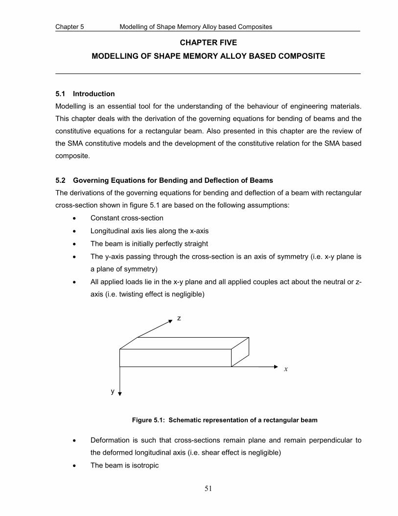
Chapter 5 Modelling of Shape Memory Alloy based Composites
51
CHAPTER FIVE
MODELLING OF SHAPE MEMORY ALLOY BASED COMPOSITE
5.1 Introduction
Modelling is an essential tool for the understanding of the behaviour of engineering materials.
This chapter deals with the derivation of the governing equations for bending of beams and the
constitutive equations for a rectangular beam. Also presented in this chapter are the review of
the SMA constitutive models and the development of the constitutive relation for the SMA based
composite.
5.2 Governing Equations for Bending and Deflection of Beams
The derivations of the governing equations for bending and deflection of a beam with rectangular
cross-section shown in figure 5.1 are based on the following assumptions:
• Constant cross-section
• Longitudinal axis lies along the x-axis
• The beam is initially perfectly straight
• The y-axis passing through the cross-section is an axis of symmetry (i.e. x-y plane is
a plane of symmetry)
• All applied loads lie in the x-y plane and all applied couples act about the neutral or z-
axis (i.e. twisting effect is negligible)
• Deformation is such that cross-sections remain plane and remain perpendicular to
the deformed longitudinal axis (i.e. shear effect is negligible)
• The beam is isotropic
z
y
x
Figure 5.1: Schematic representation of a rectangular beam

Chapter 5 Modelling of Shape Memory Alloy based Composites
52
Based on the above assumptions, the kinematics’ equation obtained from geometric relation is
as follows (Benham, Crawford & Armstrong, 1996):
R
yx =ε (5.1)
where y is the distance from the surface of the beam to the centroidal axis and R is the radius of
curvature.
Equation 5.1 holds for a beam made from any material since no material properties were
considered in its derivation. Imposing an assumption that the beam is made from a linear elastic
material, since the majority of design and analysis problems encountered in engineering deal
with elastic materials and most materials that are of engineering importance fall into this
category, we have the following constitutive relations (Gere & Timoshenko, 1999):
( )[ ]zyxxE
σσνσε +−=1
(5.2)
( )[ ]zzyyE
σσνσε +−=1
(5.3)
( )[ ]yxzzE
σσνσε +−=1
(5.4)
where ε represents normal strain, σ represents normal stress, ν is the Poisson’s ratio and E
is the elastic modulus.
For long beams, the distance between the lower and upper surface, and between the lateral side
surfaces are relatively very small, it is therefore assumed that yσ and zσ are negligible when
compared with xσ , i.e. yσ = zσ = 0 at all points through the beam.
Therefore, equations 5.2, 5.3 and 5.4 become:
xxEσε1
= (5.5)
xyEσε1
−= (5.6)
xzEσε1
−= (5.7)

Chapter 5 Modelling of Shape Memory Alloy based Composites
53
Equations 5.1 and 5.5 yield:
R
Eyx =σ (5.8)
where xσ is known as the bending or flexural stress.
Recalling from strength of materials theory, the moment, M about the neutral axis is given by:
dAyM
A
x∫∫= σ (5.9)
Substituting equation 5.8 into equation 5.9, we have:
dAyR
EdA
R
EyyM
AA
∫∫∫∫ =
= 2 (5.10)
where dAyIA
∫∫= 2 is known as the second moment of area about the neutral axis
Therefore, equation 5.10 becomes:
R
EIM = (5.11)
Equation 5.11 is known as the Euler-Bernoulli relation for linear elastic isotropic beam and the
quantityEI is known as the bending stiffness or the flexural rigidity.
Combining equations 5.8 and 5.11, we have:
I
Myyx =)(σ (5.12)
Equations 5.11 and 5.12 are the basic relations that govern the flexure of linear elastic isotropic
beams under pure bending, as imposed by the assumptions made in their derivations.
However in reality, beam deformation is not limited to pure bending (constant bending moment,
zero shear forces) but also due to combination of pure bending, arbitrary transverse loads

Chapter 5 Modelling of Shape Memory Alloy based Composites
54
( )(xMM = and shear forces varying along the length of the beam). To avoid this limitation,
Navier established a hypothesis that accounts for applied transverse loads acting in the plane of
symmetry. Based on experimental observations, some warping of the cross-section does take
place but such warping is extremely small and therefore negligible (Gere & Timoshenko, 1999).
The Navier’s hypothesis is based on the premise that under arbitrary transverse loading,
warping of the cross-section is negligible and as such, plane sections still remain plain after
deformation and that they remain perpendicular to the deformed longitudinal axis.
Therefore, invoking Navier’s hypothesis, equations 5.11 and 5.12 can be rewritten as:
)()(
xR
EIxM = (5.13)
I
yxMyxx
)(),( =σ (5.14)
Equations 5.13 and 5.14 are often referred to as engineering beam formulae. Although the
equations do not give exact solutions (due to the assumptions made), they are merely very good
approximations that yields errors of a very small percentage. Consequently, they are widely
used in engineering analyses of beams since they provide very accurate solutions to a wide
variety of engineering problems (Gere & Timoshenko, 1999):
For a beam with uniform cross-section, it can be shown that (Gere & Timoshenko, 1999):
)()(
2
2
xqdx
xMd−= (5.15)
)()(
)(2
2
xMdx
xvdxEI −= (5.16)
Differentiating equation 5.16 twice with respect to x and substituting equation 5.15 we have:
)()(
)(2
2
2
2
xqdx
xvdxEI
dx
d=
(5.17)
With EI being a constant, equation 5.17 becomes:
)()(
4
4
xqdx
xvdEI = (5.18)

Chapter 5 Modelling of Shape Memory Alloy based Composites
55
where )(xv is the lateral deflection of the beam, )(xq is the transverse load, )(xM is the
bending moment and EI is the flexural rigidity or bending stiffness.
The fourth-order differential equation 5.18 is the governing equation for beam deflection. This
equation is limited to beams having relatively large flexural rigidity (i.e. relatively stiff beams)
such that their maximum deflection is very small compared to the span of the beam.
5.3 Constitutive Relation of a Uniform Rectangular Beam
Recalling equations 5.2, 5.3, 5.4, 5.5, 5.6 and 5.7 in section 5.2 for linear elastic isotropic
material,
( )[ ]zyxxE
σσνσε +−=1
(5.19)
( )[ ]zzyyE
σσνσε +−=1
(5.20)
( )[ ]yxzzE
σσνσε +−=1
(5.21)
xxEσε1
= (5.22)
xyEσε1
−= (5.23)
xzEσε1
−= (5.24)
Equations 5.19, 5.20, and 5.21 above can be placed together in matrix notation as:
z
y
x
ε
ε
ε
= E
1
−−
−−
−−
1
1
1
νννν
νν
z
y
x
σσ
σ
(5.25)
And using index notation, we have:
kkijijijEE
σδν
σν
ε −+
=1
(5.26)
with

Chapter 5 Modelling of Shape Memory Alloy based Composites
56
ji
ji
if
ifij ≠
=
=0
1δ ( ijδ is known as kronecker delta)
and
zzyyxxkk σσσσ ++= (5.27)
From equation 5.25, the stress components are obtained in matrix form as follows:
z
y
x
σ
σ
σ
= ( )
−
−
−
−+z
y
xE
εεε
ννννννννν
νν1
1
1
)21(1 (5.28)
And in index notation form, equation 5.28 becomes:
ijkkijij
EEε
νν
εδνν
νσ
)1()21)(1( ++
−+= (5.29)
or
ijkkijij µεελδσ 2+= (5.30)
where
)21)(1( νν
νλ
−+=
E and
)1(2 νµ
+=
E are the Lame’s constants
In a more compact form, equation 5.30 takes the form:
klijklij E εσ = (5.31)
where
zzyyxxkk εεεε ++= (5.32)
In symbolic form, equation 5.31 takes the form:
εσ E= (5.33)

Chapter 5 Modelling of Shape Memory Alloy based Composites
57
5.4 Constitutive relations of Shape Memory Alloys
The objective of the constitutive model is to mathematically formulate the unified behaviour of
SMAs, such as shape memory effect, quasiplasticity and pseudoelasticity. Several constitutive
models have been and are still being proposed to predict the thermomechanical response of the
SMA. One of the earliest models is the one dimensional Tanaka’s model (Tanaka et al, 1986). It
is a macroscopic model that is derived from phenomenological thermodynamic concepts and
through experimental observations. The SMA behaviour in this model is constituted into two
equations: the mechanical constitutive equation and kinetic equation for the martensitic
transformation. The constitutive equation is obtained by the minimization of free energy using
the energy equation and the Clausius-Duhem inequality. The martensitic transformation is
considered a progressive process which can be explained through an internal variable called the
martensite fraction ξ . The kinetic equation is determined by considering a transformation micro-
mechanism and it is expressed using an exponential function in the form of ),( Τ= σξξ .
The constitutive equation by Tanaka (1986) is of the form:
TT
&&&&
∂∂
+∂∂
+∂∂
=σ
ξξσ
εεσ
σ (5.34)
where the two primary variablesε , T stand for the strain and the temperature respectively. σ is
the stress and the internal variable ξ represents the volume fraction of martensite. The
superimposed dot denotes the material derivates
The kinetic equations for the forward and reverse transformations are respectively of the form:
[ ]σξ msmmMA bTMCb +−−=→ )(exp1 (5.35a)
[ ]σξ asaaAM bTACb +−=→ )(exp (5.35b)
where the material parameters mb , mC , ab and aC based on transformation temperatures are
assumed to be constant.
Tanaka’s model was found to be able to characterize most of the behaviour of SMAs; however it
has a limitation of not being suitable for engineering applications since it only describes the
behaviour of SMAs qualitatively.

Chapter 5 Modelling of Shape Memory Alloy based Composites
58
Liang and Rogers (1990) improved on the Tanaka’s model by modifying the exponential form of
the transformation kinetics equation. They developed empirical equations in simple cosine form,
which agrees with experimental findings, to represent the martensite fraction as a function of
stress and temperature. The constitutive equation remains the same while parameters of the
equations can be determined through experiment.
Equation 5.34 can be written as:
dTT
ddd∂∂
+∂∂
+∂∂
=σ
ξξσ
εεσ
σ (5.36)
Equation 5.36 can be written as:
dTTdTdTEd ),,(),,(),,( ξεξξεεξεσ Θ+Ω+= (5.37)
Where the material functions ),,( TE ξε , ),,( TξεΩ and ),,( TξεΘ are defined as:
εσ
ξε∂∂
=),,( TE ; ξσ
ξε∂∂
=Ω ),,( T ; T
T∂∂
=Θσ
ξε ),,( (5.38)
where ),,( TE ξε , ),,( TξεΩ and ),,( TξεΘ is the Young’s modulus, the transformation tensor, and
the thermoelastic tensor, respectively.
Integrating equation 5.37 and with the assumption that the material functions are constant, the
Liang and Rogers constitutive model for SMAs which is based on a cosine function to represent
the martensite fraction takes the form:
)()()( 0000 TTE −Θ+−Ω+−=− ξξεεσσ (5.39)
where 0000 ,,, Tξεσ represent the initial state or initial condition of the SMA.
During the forward transformation, the Austenite (A) → Martensite (M), the martensite fraction
ξ is given by:

Chapter 5 Modelling of Shape Memory Alloy based Composites
59
+
++−−
=2
1])(cos[
2
1 00 ξσ
ξξ mfm bMTa (5.40)
fs
mMM
a−
=π
; m
mm
C
ab −= ;
1−
=
σddM
C sm (5.41)
And during the reverse transformation, the Martensite (M) → Austenite (A), the martensite
fractionξ is given by:
1])(cos[2
0 ++−= σξ
ξ asa bATa (5.42)
where
sf
aAA
a−
=π
; a
aa
C
ab −= ;
1−
=
σddA
C sa (5.43)
in which the constant 0ξ is the martensite fraction before phase transformation begins and aC
and mC are material properties that describes the relationship of temperature and the stress to
induce phase transformation. It is often assumed that aC and mC are equal and have a constant
value over all temperature ranges.
Although the Liang and Rogers constitutive equation for SMAs as given by equation 5.39
contains only measurable engineering variables and therefore can be practically implemented,
but it cannot properly represent the behaviour of SMAs at any temperature below sM nor at
higher temperatures when any temperature-induced martensite is present. To overcome these
limitations, a major improvement on the Liang and Rogers’s model was made by Brinson.
Brinson (1993) recognized that it is not all martensite that is converted to austenite that will
produce the recovery stress but only the stress induced martensite is responsible for the SME.
In improving the Liang and Rogers’s model, Brinson firstly separated the martensite fraction ξ
into the stress induced and the temperature induced martensite fractions as follows:
TS ξξξ += (5.44)
Chapter 5 Modelling of Shape Memory Alloy based Composites
60
where Sξ is the stress induced (detwinned) martensite fraction with a single martensitic variant,
and Tξ is the temperature induced (twinned) martensite fraction with multiple martensitic
variants. It suffices to say that the separation of the martensite fraction ξ into two distinct
components accurately represents the microscopic behaviour of the SMA.
Brinson further improved on the Liang and Rogers’s model by considering the dependence of
the Young’s modulus E and transformation tensor Ω on the martensite fractionξ has confirmed
by experimental investigation. Introducing the non-constant material functions, facilitate the
prediction of the SME due to change in material properties, for example, to account for the
changes in the Young’s modulus with increasing temperature.
Therefore, with the decomposition of the martensite fraction and the dependence of the Young’s
modulus and transformation tensor on the martensite fraction being taken into consideration,
Brinson’s model (1993) which can be utilized over a wide range of temperature is given by:
)())()())()( 000000 TTEE SS −Θ+Ω−Ω+−=− ξξξξεξεξσσ (5.45)
where the subscript ‘o’ indicates the initial values and
)()( ama EEEE −+= ξξ
)()( ξεξ EL−=Ω (5.46)
where mE is the modulus value for the SMA when it is 100% martensite, aE is the modulus
value for the SMA when it is 100% austenite, and Lε is the maximum recoverable martensitic
strain which may be constant for a wide temperature range.
5.5 Constitutive Relation of SMA based Composite Beam
A mechanics of materials approach will be applied to derive the thermoelastic constitutive
relations governing the SMA/polyurethane composite beam. When SMA wires are embedded in
a matrix material, a composite is formed. If the SMA wires are activated, recovery forces, which
depend on the constraint provided by the surrounding matrix, will be induced. Recalling from
section 5.3, the constitutive equation for a beam is given by:
xx Eεσ = (5.47)

Chapter 5 Modelling of Shape Memory Alloy based Composites
61
Equation (5.47) can be written as:
x
xEεσ
= (5.48)
Recalling from section 5.4, the constitutive equation for SMA is given by:
))(())(())(( 0000 TTE SS −Θ+−Ω+−=− ξξξξεεξσσ (5.49)
In determining the effective properties of the SMA/polyurethane composite beam, the volumetric
representation of the composite, which is shown in figure 5.2, was considered with the following
assumptions:
• there is perfect bonding between the SMA wire and the matrix material, thus the
SMA wire and the surrounding matrix material experience the same strain
• the SMA wire exhibit a TWSME
• the SMA wire was heated above fA
• the linear elastic limit of the SMA wire was not exceeded (Hooke’s law is obeyed)
• transformation strains are considered in only one direction (x-axis)
For a perfect adherence between the SMA wire and the surrounding matrix, kinematics requires
that the strain in the SMA, the matrix, and the resulting composite must be equal. Thus,
cms εεε == (5.50)
where ε is the strain, and the subscripts s, m and c is refer to the SMA, matrix and composite.
x
cc F,σ
Figure 5.2: Representative volume of SMA/polyurethane composite beam
SMA
Polyurethane matrix

Chapter 5 Modelling of Shape Memory Alloy based Composites
62
Upon activating the SMA, the surrounding matrix will prevent the SMA from recovering the initial
strain (constrained recovery) resulting in the generation of recovery stress and hence recovery
force. Considering the resultant force acting on the SMA/polyurethane composite in the x-
direction, as shown in figure 5.2, is shared between the SMA and the polyurethane matrix
material and can be written as:
ssmmsmc AAFFF σσ +=+= (5.51)
where cF , mF , sF is the axial force on the entire composite, matrix, and SMA respectively.
But,
c
cc
A
F=σ (5.52)
Therefore,
c
ssmmc
A
AA σσσ
+= (5.53)
ssmmc VV σσσ += (5.54)
where c
mm
A
AV = and
c
ss
A
AV = are the volume fractions of the matrix and the SMA respectively
and cA , mA , sA are the cross-sectional area of the entire composite, matrix, and SMA respectively
and cσ , mσ , sσ are the stress of the entire composite, matrix, and SMA respectively.
a
b
SMA wire
Surrounding Matrix
Figure 5.3: Cross-section of SMA/polyurethane composite beam

Chapter 5 Modelling of Shape Memory Alloy based Composites
63
Utilizing figure 5.3, the volume fractions of SMA ( sV ) and polyurethane matrix ( mV ) can be
obtained as follows:
abAc = (5.55)
4
2dnAs
π= (5.56)
where n is the number of SMA wires and d is the diameter of the SMA wire embedded in the
polyurethane matrix. Therefore,
c
sA
dnV
4
2π= (5.57)
But
1=+ sm VV (5.58)
Hence,
sm VV −= 1 (5.59)
At a temperature sAT ≥ , the SMA effect is activated and the respective stress sσ and mσ in the
SMA and matrix material becomes:
rss E σεσ += (5.60)
)( TE mmm ∆−= αεσ (5.61)
where sE and mE are the Young’s modulus of the SMA and polyurethane matrix respectively. mα
is the thermal coefficient of expansion of the polyurethane matrix, SA is the austenite start
temperature,ε is the strain, T∆ is the change in temperature, and rσ is the recovery stress
generated by the SMA. It suffices to mention that sE and rσ is temperature dependent. The
recovery stress rσ which is obtainable from Brinson’s model also depends on prestrain.

Chapter 5 Modelling of Shape Memory Alloy based Composites
64
Substituting equations 5.60 and 5.61 into equation 5.54, the one-dimensional stress-strain
relation in the x-direction for the SMA/polyurethane composite can be expressed as:
)()( rssmmmc EVTEV σεαεσ ++∆−= (5.62)
Expanding equation 5.62 we have:
TEVVEVEV mmmrsssmmc ∆−++= ασεεσ
= TEVVE mmmrs ∆−+ ασε (5.63)
where
ssmm EVEVE += (5.64)
Substituting equation 5.59 into equation 5.64, we have:
ssms EVEVE +−= )1( (5.65)
Equation 5.65 is referred to as the law of mixtures for the modulus of elasticity in the longitudinal
direction. The variation of the moduli mE and sE is linear, and the volume fractions mV and sV
take values that vary from 0 to 1.
When the SMA effect is inactivated at a temperature sAT < , equation 5.60 becomes:
)( TE sss ∆−= αεσ (5.66)
where sα is the thermal coefficient of expansion of the SMA.
Substituting equations 5.64 and 5.66 into equation 5.63, the one-dimensional stress-strain
relation in the x-direction for the SMA/Polyurethane composite becomes:
)()( TEVTEV sssmmmc ∆−+∆−= αεαεσ (5.67)
Expanding equation 5.67 and simplifying, we have:

Chapter 5 Modelling of Shape Memory Alloy based Composites
65
TEVEVEVEV sssmmmssmmc ∆+−+= )()( ααεσ (5.68)
In a compact form, equation 5.68 can be written as:
)( TEc ∆−= αεσ (5.69)
where E is as given by equation 5.65 and
E
EVEV sssmmm )( ααα
+= (5.70)
By definition, the Poisson’s ratio v is the ratio of the transverse strain tε to the longitudinal
strain lε .
If w represents the width of the composite and L represents its length, therefore
LLw
w
v∆
∆−= (5.71)
or
∆−=∆
L
Lv
w
w (5.72)
But
sm www += (5.73)
and
sm www ∆+∆=∆ (5.74)
Based on the assumption of perfect bonding between the SMA and the surrounding
polyurethane matrix, we have:
sm LL ∆=∆ (5.75)
Recalling equation 5.72 we can write as follows:

Chapter 5 Modelling of Shape Memory Alloy based Composites
66
∆−=∆
L
Lv
w
wm
m
m (5.76)
∆−=∆
L
Lv
w
ws
s
s (5.77)
Equations 5.76 and 5.77 can be re-written respectively as:
∆−=L
Lwvw mmm (5.78)
∆−=L
Lwvw sss (5.79)
Substituting equations 5.78 and 5.79 into equation 5.74, and factorizing, we have:
( )L
Lwvwvw ssmm
∆+−=∆ (5.80)
Dividing both sides of equation 5.80 byw , we have:
L
L
w
wv
w
wv
w
w ss
mm
∆
+−=
∆ (5.81)
= ( )L
LVvVv ssmm
∆+− (5.82)
mV and sV in equation 5.82 are the respective volume fraction of the surrounding matrix and
SMA. Comparing equations 5.72 and 5.82, it could be established that:
ssmm VvVvv += (5.83)
Equations 5.65 and 5.83 are the effective modulus and the Poisson’s ratio of the
SMA/Polyurethane composite beam respectively.

Chapter 5 Modelling of Shape Memory Alloy based Composites
67
Table 5.1: Comparison of major macroscopic modelling of SMA
Model
Constitutive Equation
Kinetic Equation for
Transformation
Tanaka
(1986)
TT
&&&&
∂∂
+∂∂
+∂∂
=σ
ξξσ
εεσ
σ
Exponential Form
Liang and
Rogers
(1990)
)()()( 0000 TTE −Θ+−Ω+−=− ξξεεσσ
Cosine Function
Brinson
(1993)
)())()())()( 000000 TTEE SS −Θ+Ω−Ω+−=− ξξξξεξεξσσ
Cosine Function
Table 5.2: Comparison of Young’s modulus
Materials
Constitutive Equation
Young’s Modulus ( E )
Polyurethane Beam
εσ E=
E
NiTi SMA (Brinson’s
Model)
())()())()( 000000 TTEE SS −Θ+Ω−Ω+−=− ξξξξεξεξσσ
)()( AMA EEEE −+= ξξ
SMA/Polyurethane
Composite (activated
SMA)
TEVVE mmmrs ∆−+= ασεσ
Msmm EVEVE +=
SMA/Polyurethane
Composite
(inactivated SMA)
TEVEVE sssmmmc ∆+−= )( ααεσ
Asmm EVEVE +=
Where:
ξ is the volume fraction of martensite
E is the Young’s modulus for the “virgin” polyurethane
AE is the Young’s modulus for the SMA in the austenite phase
ME is the Young’s modulus for the SMA in the martensite phase
sV is the volume fraction of the SMA
mV is the volume fraction of the polyurethane matrix

Chapter 6 Experimental Work
68
CHAPTER SIX
EXPERIMENTAL WORK
6.1 Introduction
The understanding of the mechanical properties and behaviour of engineering materials to end
users is very crucial in material selection. In this work, experiments were conducted on the virgin
polyurethane and NiTi SMA/polyurethane composites so as to obtain their respective Young’s
modulus, tensile strength, fracture load, elongation at break and bending stiffness for the
purpose of comparisons. The pullout test which is also known as the debonding test was carried
out on NiTi SMA/polyurethane composites so as to ascertain the load that causes debonding.
The effect of temperature on the debonding load and the effect of temperature on deformation
were also investigated. The specimens utilized for these experiments were produced using the
vacuum casting manufacturing process. The facilities in the department of Industrial Engineering
at The University of Stellenbosch, Stellenbosch were utilized for casting the specimens. The
mechanical tests were conducted in the Strength of Materials Laboratory at the department of
Mechanical Engineering, Cape Peninsula University of Technology, Bellville Campus.
6.2 Vacuum Casting Process
The vacuum casting process of manufacturing which is most widely used for manufacturing
polymer based matrix composites was utilized for the production of the specimens. The merits of
the vacuum casting over alternative manufacturing processes such as injection moulding and
extrusion include the following: the mould is simpler and cost effective, cast material is relatively
free of residual stress and viscoelastic memory, and it is best suited for low production quantities
(Groover, 2002). The vacuum casting process permits a high degree of flatness and desirable
optical qualities. Such flatness and clarity are difficult if not impossible to be achieved with other
processes. But despite these merits, the casting process has an undesirable effect of shrinkage
of the cast part during curing (solidification). However, this shortcoming can be minimized by
customising the mould and adhering strictly to the manufacturing procedure of the casting
equipment manufacturers and the technical instructions of the polyurethane resins. This process
consists of three major steps: production of the master part, preparation of the mould and
casting of the specimens.
6.3 The Production of the Master Parts
The master part for the tensile test specimens, figure 6.1 and the master part for the rectangular
cross-sectioned beams, figure 6.2, were produced via rapid prototyping at the Centre for
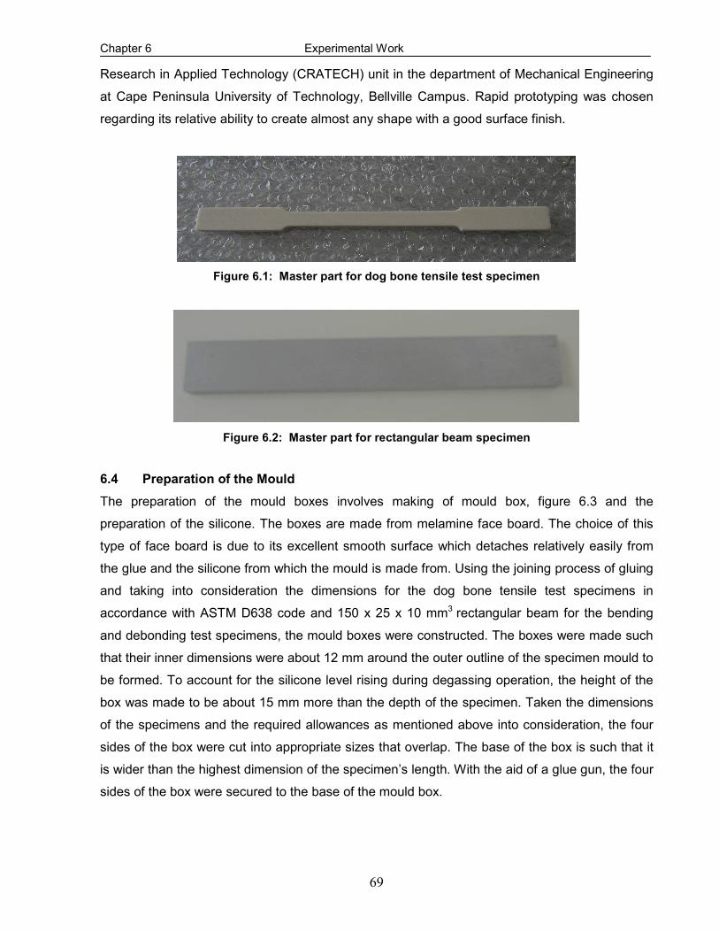
Chapter 6 Experimental Work
69
Research in Applied Technology (CRATECH) unit in the department of Mechanical Engineering
at Cape Peninsula University of Technology, Bellville Campus. Rapid prototyping was chosen
regarding its relative ability to create almost any shape with a good surface finish.
Figure 6.1: Master part for dog bone tensile test specimen
Figure 6.2: Master part for rectangular beam specimen
6.4 Preparation of the Mould
The preparation of the mould boxes involves making of mould box, figure 6.3 and the
preparation of the silicone. The boxes are made from melamine face board. The choice of this
type of face board is due to its excellent smooth surface which detaches relatively easily from
the glue and the silicone from which the mould is made from. Using the joining process of gluing
and taking into consideration the dimensions for the dog bone tensile test specimens in
accordance with ASTM D638 code and 150 x 25 x 10 mm3 rectangular beam for the bending
and debonding test specimens, the mould boxes were constructed. The boxes were made such
that their inner dimensions were about 12 mm around the outer outline of the specimen mould to
be formed. To account for the silicone level rising during degassing operation, the height of the
box was made to be about 15 mm more than the depth of the specimen. Taken the dimensions
of the specimens and the required allowances as mentioned above into consideration, the four
sides of the box were cut into appropriate sizes that overlap. The base of the box is such that it
is wider than the highest dimension of the specimen’s length. With the aid of a glue gun, the four
sides of the box were secured to the base of the mould box.

Chapter 6 Experimental Work
70
The four sides of the masterpart were taped with coloured packaging tape. The tape facilitates
the parting of the mould into two parts which are not necessarily required to be equal. Four small
sized brazing rods that would raise the masterpart above the base of the box were glued
Figure 6.3: Mould box
to the base of the masterpart. A strip of the face board, having almost the same length as the
base was cut and a 2 mm diameter hole was drilled through it. A glue stick was pushed through
the hole created in the strip. One end of the glue stick was glued to the top part of the
masterpart. The diameter of the stick is such that it is snugly fitted to the strip and its height is
such that it protrudes above the strip by at least 20 mm. The significance of the glue stick is that
it facilitates the positioning of the master part in the box as well as creating an inlet through
which the resins from which the specimens are produced can be poured.
To cast the mould, the vacuum chamber of the MCP 4/04 vacuum casting machine is required to
be air - free so as to obtain moulds with minimum defects. To achieve this, the machine was
started and the vacuum chamber was evacuated for about twenty-five (25) minutes. While the
vacuum chamber was being evacuated, a known quantity by mass of silicone, Wacker Silicone
grade Elastosil (EL) M 4644 A and hardener, Wacker Silicone grade Elastosil (EL) M 4644 B, to

Chapter 6 Experimental Work
71
be poured into the box were obtained. Disregarding the excess height of 15 mm, the volume of
the constructed box was determined and multiplied by the density of the silicone to obtain the
actual mass of the silicone required. In order to make allowance for the silicone that will be left in
the bucket after pouring, 50 grams was added to the calculated mass of the silicone. The empty
bucket required for the degassing of the silicone was thoroughly cleaned and placed on the
weighing scale. To forestall the empty bucket from contributing to the effective mass of the
silicone, the scale was zeroed and afterwards, the required amount of silicone was poured into
the bucket. The weighing scale was again reset to zero, and thereafter, hardener, which is one-
tenth by part of the silicone, was poured into the bucket. The resulting content of the bucket was
vigorously blended for about fifteen (15) minutes with the mixing paddle which is operated by
electrically powered drilling machine. The objective of this exercise was to significantly reduce
the amount of trapped air inside the silicone in order to have a high quality mould.
It suffices to say that the blending of the silicone mixed with the hardener was not sufficient to
remove the trapped air. Consequently, the bucket containing the silicone which had been
previously made almost air-free was placed inside the vacuum chamber and the latter was
degassed for further twenty-five (25) minutes so as to get rid of or at least, to considerably
reduce the amount of the trapped air in the silicone. Initially, it was observed that the silicone
level rose rapidly as if it was boiling. This was due to the presence of the trapped air. Intermittent
but momentary pressure-shooting ensured the degassing of the silicone.
Meanwhile, during the process of degassing, the box constructed from face board was
thoroughly cleaned, taped (so as to preclude leakage of the silicone) and placed on a flat
surface where the pouring of the degassed silicone would be done. The masterpart was then
placed inside the box with the aid of the brazing rods which served as supports and the strip
which rested on top of the box and glued to it. After the degassing, the silicone was carefully
poured into the box which now contained the masterpart. The pouring process was achieved
within ten (10) minutes and the box was immediately returned to the vacuum chamber and the
latter was degassed for about thirty (30) minutes. Thereafter, the mould box was taken out of the
vacuum chamber and left overnight for the silicone to cure at room temperature. The silicone
mould was detached from the box with the aid of the packaging tape which served as the parting
plane, the mould was cut into two parts which are not necessarily equal, and the glue stick was
also removed from the silicone mould accordingly.

Chapter 6 Experimental Work
72
6.5 Casting of the Specimens
The chemical composition of the NiTi SMA as obtained from Johnson Matthey, San Jose, CA,
USA and the technical data for the semi rigid polyurethane resin, a Smooth-On product, that
were utilized to produce the specimens are as given in tables 6.1 and 6.2 respectively. The
choice of this resin was based on merits of low viscosity and relative ease of usage. Besides,
cured castings are semi rigid, impact resistant, corrosion resistant and negligible shrinkage. In
addition to these, the curing process of the thermosetting matrix will not destroy the actuating
capability of the embedded NiTi wires (Paine and Rogers, 1991).
The ability of the shape memory materials to efficiently operate within the host matrices is,
amongst others, dependent on their integrity (Loughlan and Thompson, 2001). Therefore prior to
integrating SMA wires into the polyurethane host matrices, ageing and prestraining treatments of
the virgin (as obtained from the manufacturers) NiTi SMAs were performed for the enhancement
of their inherent performance characteristic of stable strain recovery action. A detail discussion
of ageing and prestrain are discussed in sections 6.6 and 6.7 respectively.
Table 6.1: Chemical composition of NiTi SMA wire
Diameter
(mm)
Ni
%
Ti
%
C
%
0
%
Others
%
Temper Surface Active
fA
(0C))
1 55.32 44.67 ≤ 0.05 ≤ 0.05 0.20 Straight Annealed
Oxide 60.7
Others: Al, Co, Cr, Cu, Fe, Mn, Mo, Nb, Si, W
Table 6.2: Technical data for 60D polyurethane resin
Mix Ratio (pbv)
Colour Pot Life
De-mould Time
Mixed Viscosity
Density Ultimate Tensile Strength
Elongation at break
Shrink
1A:1B Brown 5 min 20 min 1500 cps
1.05, g/cm
3
2200 psi 30% 0.15 in/in
Grooves that would accommodate the NiTi SMA wires were created to the two segments of the
silicone mould. It should be noted that there was no groove created in the mould during the
manufacturing of the virgin polyurethane specimens. The inner portions of the two halves of the
silicone mould were thoroughly cleaned with the use of soft cloth and methylated spirit and dried
accordingly, and were sparingly sprayed with silicone demould spray so as to ensure that the
specimen detaches from the silicone mould with ease after curing. The treated NiTi SMA wire
was properly located in the groove created in one half of the mould. The two mould halves were
coupled together to form the cavity and the split line was sealed by running packaging tape
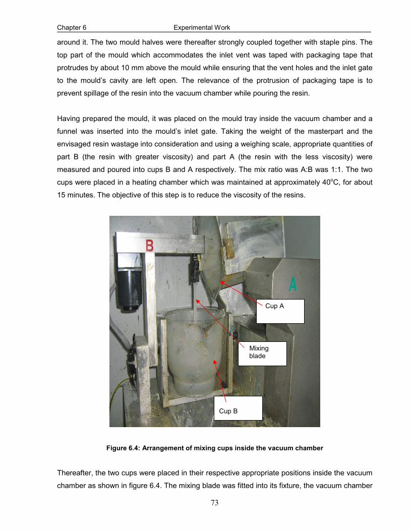
Chapter 6 Experimental Work
73
around it. The two mould halves were thereafter strongly coupled together with staple pins. The
top part of the mould which accommodates the inlet vent was taped with packaging tape that
protrudes by about 10 mm above the mould while ensuring that the vent holes and the inlet gate
to the mould’s cavity are left open. The relevance of the protrusion of packaging tape is to
prevent spillage of the resin into the vacuum chamber while pouring the resin.
Having prepared the mould, it was placed on the mould tray inside the vacuum chamber and a
funnel was inserted into the mould’s inlet gate. Taking the weight of the masterpart and the
envisaged resin wastage into consideration and using a weighing scale, appropriate quantities of
part B (the resin with greater viscosity) and part A (the resin with the less viscosity) were
measured and poured into cups B and A respectively. The mix ratio was A:B was 1:1. The two
cups were placed in a heating chamber which was maintained at approximately 40oC, for about
15 minutes. The objective of this step is to reduce the viscosity of the resins.
Figure 6.4: Arrangement of mixing cups inside the vacuum chamber
Thereafter, the two cups were placed in their respective appropriate positions inside the vacuum
chamber as shown in figure 6.4. The mixing blade was fitted into its fixture, the vacuum chamber
Cup A
Mixing blade
Cup B

Chapter 6 Experimental Work
74
door was closed, and the pump was switched on to facilitate the degassing of the vacuum
chamber. The degassing was carried out for about twenty (20) minutes. While the degassing
continued, the mixer was simultaneously operated to stir the resin in cup B. The significance of
the stirring was to accelerate the degassing process. Immediately after degassing and just
before casting, the resin in cup A was poured into cup B and further stirring was done for
additional two (2) minutes. While stirring continued, the chamber was given pressure shots
intermittently to burst air bubbles thereby making the resin surface bubble-free. Thereafter, cup
A was swivelled back to its position and the content of cup B was carefully poured into the
mould’s cavity via the funnel until resin was pouring out of the vents. The pouring exercise was
accomplished within a period of three (3) minutes.
As soon as the resin was pouring out from the vent, cup B was swivelled back to its initial
position and the mould remained in the chamber for another two (2) minutes with the vacuum
being slowly released to avoid splashing of resin. The mould with its content was thereafter
removed from the vacuum chamber and placed on a flat surface and the resin was allowed to
solidify at room temperature for about two (2) hours. Although a de-moulding time of twenty (20)
minutes was recommended by the resin suppliers, the experience gathered during the
manufacturing exercise showed that this duration was grossly insufficient, except if the curing is
done at an elevated temperature.
Based on the objective of this research, enhanced curing in a furnace would be inappropriate for
the SMA based composites, since the embedded SMA wire is temperature sensitive. It suffices
to say that the temperature inside the vacuum chamber was not sufficient to alter the property of
the embedded SMA. After solidification, the staple pins and packaging tape were removed from
the mould. The two mould halves were pulled apart and the specimen which was stuck into one
of the mould’s halves was carefully removed and the vent pieces still attached to the specimen
were broken off. It should be noted that the same casting process was used for both virgin and
SMA/polyurethane composite specimens.
6.6 Ageing of NiTi Shape Memory Alloy wires
SMA wires in untreated form have no significant value since applications depend largely on
recovery of deformation and perfect bonding to the host matrices. The prime significance of
ageing is to among other reasons ensure homogeneous behaviour of the SMA wires (Yi & Gao,
2003) and to obtain a zero prestrain state (i.e. residual stress-free). Ageing also erases the
inconsistent yield point associated with the untreated SMA wire (Mukhawana & Philander, 2006).
One (1) mm diameter NiTi SMA wire obtained from Johnson Matthey, San Jose, CA, USA were

Chapter 6 Experimental Work
75
cut into the required lengths using a guillotine cutting machine. They were put inside the furnace
which had been preset to the required ageing temperatures. All the specimens were cut from the
same reel to ensure that their properties are uniform. Four (4) ageing temperatures of 250oC,
300oC, 350oC and 400oC were considered. The SMA wires were left in the furnace for about ten
(10) hours and subsequently taken out and allowed to cool down to room temperature.
Figure 6.5: Experimental set up for pre-straining NiTi SMAs
The treated and untreated wires in their martensitic phase were pulled to fracture by a
Hounsfield Tensile Testing Machine. The cross-head displacement speed for all the tests was 5
mm/min with a load range of 0 -1000 N. An insight to the choice of the displacement speed was
given by the work of Philander (2004). The ambient temperature for the entire test was
approximately 24oC and the gauge length of the wire was 150 mm. The experimental set up is
shown in figure 6.5 and a detailed discussion of the tensile test that was used to pull the wires to
destruction is presented in section 6.9. The behaviour of the wires under different ageing
temperatures is found in appendix C. Figure 6.6 illustrates the combined stress-strain
relationship of the four ageing temperatures. The respective Young’s modulus for the virgin and
the aged wires were obtained from the initial linear elastic portion of the stress-strain curves.
Load cell
Upper jaw
Lower jaw
NiTi SMA wire

Chapter 6 Experimental Work
76
0
200
400
600
800
1000
1200
0 0.02 0.04 0.06 0.08 0.1 0.12 0.14 0.16
Strain
Str
ess (
Mpa)
Figure 6.6: Stress vs. Strain at different ageing temperatures
Tensile tests of NiTi wire were also conducted when the NiTi wire was activated (i.e. at an
elevated temperature) to obtain its Young’s modulus at the high temperature phase and to also
characterise its behaviour. The testing procedure was similar to the procedure described
previously. However, an electric current of 3 amps was supplied by a DC source to activate the
NiTi SMA wire. Insight to the current required was from the work of Shimamoto et al, 2004. The
temperature of the wire was directly measured by a sensitive thermocouple. To ensure that the
property of the wire was not destroyed, the austenite finish temperature was not exceeded and
heating was not continuous as recommended by Umezaki, 2000. The current flow was being
intermittently disturbed so as not to generate unnecessary heat in the wires once the austenite
finish temperature is attained. It could be observed that the NiTi SMA exhibits the same trend
which confirms consistency in its characteristics features when treated, the details of the
experimental results are presented and discussed in Chapter 7.
6.7 Prestraining of NiTi Shape Memory Alloy wires
It has been reported in the literature that the good characteristics that are inherent in the NiTi
SMAs can only be utilized if some deformation can be induced to the NiTi SMA wire (Bruck and
Moore, 2002; Zheng et al, 2005). The amount of prestrain determines the recovery stress that
can be generated by the NiTi SMAs upon activation. The higher the level of prestrain, the higher
the recovery stress but there is a limit to the amount of prestraining (Zheng et al, 2005).
Therefore, the objective of prestraining was to induce recoverable deformation to the NiTi SMA
wires that would be embedded into the polymeric matrices. For this research activity, a prestrain
of 3%, which is representative of the prestrain level in some published works, was considered. In
400 degrees
350 degrees
300 degrees

Chapter 6 Experimental Work
77
order to induce a 3% prestrain, a wire with gauge length of 150 mm must be deformed by 4.5
mm. One of the 1 mm diameter NiTi SMA wires that were aged at a temperature of 250oC was
utilized for determining the prestrain load. The gauge length of the wire was 150 mm, the cross
head displacement speed was 5 mm/min and the maximum load was set at 400 N to forestall
fracture of the specimen. The experiment was conducted at an ambient temperature of 24oC.
The experimental set up is shown in figure 6.5 and a detailed discussion of the tensile test that
was used to deform the wire is discussed in section 6.9. The loads and the corresponding
extensions were stored by the PC-based data acquisition and control system. The load-
extension curves are found in appendix D. In order to obtain the load that will produce an
extension of 4.5 mm which translates to 3% prestrain to the 150 mm wire, a straight line was
drawn along the initial elastic portion of the load-extension curve. Another straight line, parallel to
the previous one, was projected from a point 4.5 mm on the displacement axis to the load-
displacement curve as shown in figure 6.7.
0
20
40
60
80
100
120
0 2 4 6 8 10
Extension (mm)
Lo
ad
(N
)
Figure 6.7: Load for 3% pre-strain
4.5 mm
55 N

Chapter 6 Experimental Work
78
6.8 Time response of the NiTi SMA wire
The efficiency of any shape memory actuator is very critical to the design of the adaptive
structure. This efficiency is a function of the time the austenite start temperature, SA and the
time the austenite finish temperature, fA are attained. A more scientific way to establish the
transformation parameters would have been the utilization of a differential scanning calorimeter
(DSC), but due to the constraint of its non-availability as at the time of conducting this research,
an approximate estimation of the activation time and the temperature at which this occurred was
conducted on the SMA wires.
Figure 6.8: Twisted NiTi SMA wire before activation
Three SMA wires twisted in various complex degrees of twist as shown in figures 6.8 were
tested independently. A current of 3 amps supplied by a DC source was used to activate the
wires. It was observed that the activation began 8 seconds and at a temperature of
approximately 32oC after the supply of current. Full shape recovery of the wires, as shown in
figure 6.9, occurred at a temperature of approximately 45oC and 60 seconds from the time the
current was applied to the SMA wires. This test was conducted at an ambient temperature of
25oC. It was assumed that the heat loss from the SMA wire was negligible since the duration
was very small. Consequently, the established SA and fA for this research activity is
respectively taken as 32oC and 45oC.
Figure 6.9: Full shape recovery of the twisted NiTi SMA wire
Twisted NiTi
SMA wire
Thermocouple
NiTi SMA wire (fully transformed)

Chapter 6 Experimental Work
79
6.9 Pullout Test
The actuation forces that are induced by the embedded SMA wire in a composite depend on the
constraint provided by the surrounding matrix (Bruck et al, 2002). Interfacial bond strength of the
SMA wire- host matrix interface determines the limit of the amount of actuation force that can be
exerted by the wire on the matrix, and the load at which the SMA wire separates from the
polymeric host dictates the maximum recovery force that the implanted SMAs can generate. If
debonding occurs, the embedded SMA wire would have no influence on the polymeric host
material. The importance of investigating the interfacial bond strength between the SMA wire
and the polymeric host cannot therefore be overemphasized.
Amongst the various mechanical interface testing methods designed to determine the interfacial
bond strength, the single SMA pullout test is the most widely used (Umezaki, 2000). Loughlan
and Thompson (2001) reported that the embedded length of the SMA in the host matrix does not
significantly affect the actual interfacial shear strength, however a longer length will require a
higher pullout load because failure, in the form of a circumferential crack, must travel along the
length of the SMA wire before the interface becomes short enough to completely fail. The
objective of this test was to determine the load at which debonding occurred. The specimens
utilized for this test were produced by the vacuum casting procedure discussed in section 6.5.
6.9.1 Experimental Procedure
A Hounsfield tensile testing machine was utilized for this test. The pullout test was performed by
pulling the NiTi SMA wire until it began to separate from the polyurethane matrix. The specimens
utilized are rectangular cross-sectioned beams with SMAs implant. They are manufactured via
the vacuum casting process described in section 6.5. The experimental set up is shown in figure
6.10. One end of the polymeric host was fixed onto the lower grip assembly. Although the
diameter of the SMA is relatively smaller than the thickness of the polymeric host, however, the
choice of the jaw was such that undue compressive stress which might affect the experimental
result was forestalled from being induced to the SMA wire. Care was taken in fixing the
specimen into the lower jaw. The cross head which has the load cell lowered and the protruded
SMA wire in the other end of the specimen was secured into the upper jaw.
With this arrangement the test for the specimen with inactivated SMA commenced. As the upper
cross head moved vertically upward, it induced a steadily increasing load to the specimen
causing the “pulling out” of the SMA wire. As the test progressed, the load versus wire
displacement plot was observed. As soon as the wire completely detached from the polymeric
host, the test was terminated. The load and displacement data were stored by the PC based

Chapter 6 Experimental Work
80
data acquisition and control system. The pullout load-displacement graphs are found in appendix
E. Regarding the test with activated SMA wire, the experimental set-up and procedure were
similar to the one for inactivated SMA but the NiTi wire was activated by direct heating with a
current of 3 amps from a DC source.
Figure 6.10: Experimental set up for pullout test
.
The results of the wire pull out tests indicated that, for the same embedded length, the
debonding load at room temperature is higher than that of an elevated temperature (i.e. when
the SMA wire was activated) however the complete separation of the wire from the matrix
occurred over a longer displacement. What accounted for the difference between the two loads
is discussed in Chapter 7.
6.10 Tensile Test
The resistance to load by an engineering material, the load required to fracture it, and the
amount it extends before it is fractured are important properties for the purpose of design. For
most materials, the initial resistance to load or the elastic modulus, and the point of permanent
deformation, are obtained from plots of stress against strain. Analysis of load-elongation or
Specimen
Load cell

Chapter 6 Experimental Work
81
stress-strain curves can convey much information about the material being tested, and it can
help in predicting its behaviour. The factors involved in the tensile test are the specimen shape
and dimensions, the choice of grips and the displacement rate among others. When performed
properly, the tensile test can be an invaluable tool for material characterization. The objective of
this test was to determine the fundamental mechanical properties of both virgin and NiTi
SMA/polyurethane composites which are required for design purposes. The results obtained
were analysed to ascertain the significance of embedding SMAs in polyurethane. This test was
accomplished by gripping opposite ends of the specimens and pulling them apart by subjecting
them to a gradually increasing uniaxial load until fracture occurred.
Figure 6.11: Dog bone virgin polyurethane tensile test specimen
Figure 6.12: Dog bone NiTi SMA/polyurethane specimen (single wire)
Figure 6.13: Dog bone NiTi SMA/polyurethane specimen (double wire)
The dog bone specimens for the virgin polyurethane figure 6.11 and NiTi SMA/polyurethane
composites figures 6.12 and 6.13 for this test were manufactured via the vacuum casting
NiTi SMA wire
NiTi SMA wires
Virgin Polyurethane

Chapter 6 Experimental Work
82
process described in section 6.5. The essence of the wider ends is to facilitate firm gripping of
the specimen while the narrower middle allows for the concentration of stress in the test area
where fracture and most of the strain occur. The gauge length and the original cross sectional
area of the specimens were 60 mm and 6 x 12.5 mm2. The tensile test was conducted on four
specimens per each of the virgin polyurethane and the NiTi SMA/polyurethane composite
respectively.
6.10.1 Experimental Procedure
A Hounsfield Tensile Testing Machine was utilized for this test. The set up for the experiment
conducted without activating the embedded SMA wire is shown in figure 6.14 and figure 6.15
shows the experimental set up for the elevated temperature test. To ensure effective gripping,
split-grip devices that forestall slippage were employed. Tests were performed at an ambient
temperature of 25oC that was maintained to within + 1oC during any single test. The loading
rates utilized in the experiments were chosen to be sufficiently low so as to suppress significant
temperature variations during testing. Hence, all experiments were deemed to have taken place
under essentially isothermal conditions.
Figure 6.14: Experimental set up for tensile testing of inactivated SMA/composite
Load cell
Specimen

Chapter 6 Experimental Work
83
One end of the specimen was inserted into the fixed lower grip assembly mounted to the base of
the tensile machine and the other end was located into the movable upper grip assembly
attached to the cross head which bears the load cell. Care was taken while tightening to ensure
that the specimen did not bend. Also, the vertical alignment of the grips and the specimen were
taken into consideration. Offsets in alignment will create side loading or bending stresses and
will result to lower tensile stress readings. Misalignment may even cause the specimen to
fracture outside the gauge length. The auxiliary PC based data acquisition and control system
was switched on to open the test window and to set the test parameters. The crosshead
displacement speed of 5 mm/min and the load range of 0–5000 N were set and the experiment
was initialized.
Figure 6.15: Experimental set up for tensile testing of activated SMA/composite
With one end of the specimen rigidly fixed to the lower part of the machine, a steadily increasing
load was applied to the specimen causing its elongation as the upper cross head moved
vertically upwards. The load cell measured the resultant force that built up in the material as its
length was increasing. As the pulling proceeded, the elongation of the specimen and the
corresponding load were acquired and stored by the integrated PC based data acquisition and
control system. As soon as fracture of the specimen occurred, the test was terminated. The
Data acquisition and control system
DC Power source
Specimen
Thermocouple

Chapter 6 Experimental Work
84
above steps were repeated for all the virgin polyurethane specimens and SMA/polyurethane
composites in which the embedded SMAs were not activated.
Regarding the tests at elevated temperature, the NiTi wires were activated by direct heating with
a current of 3 amps from a DC source. The choice of the direct method of heating over indirect
method of exposing the SMA/polyurethane composite to external temperature (a controlled
heated environment) is due to the merit of efficient heat transfer. In the case of indirect heating,
the polymeric host constitutes an impediment to heat transfer to the NiTi wire from an external
temperature source.
Utilizing the specimen’s parameters, stress and strain values were respectively obtained from
the experimental data of load and elongation acquired by the integrated PC. Stress-strain curves
were constructed for the virgin polyurethane and SMA/polyurethane composites. The fracture
loads, elongations at break, the tensile strength and Young’s modulus of elasticity obtained are
presented and discussed in chapter 7.
6.11 Four Point Bending Test
The four point bending test is a very useful test for determining the bending stiffness of
engineering materials. The bending test was conducted on rectangular beam specimens that
were produced by the vacuum casting process discussed in section 6.5. However, a strain
gauge was fastened by means of glue to the mid-point of the longitudinal axis of each of the
composite beams at the lower portion that contains the NiTi wire as shown in figure 6.16. Power
cables were connected to the two terminals of each of the strain gauges by soldering. These
cables, which were connected to a Wheatstone bridge, facilitated the measurement of the strain
when the beam was loaded.
Figure 6.16: SMA/polyurethane composite beams with fastened strain gauges
Strain gauge

Chapter 6 Experimental Work
85
The dimensions of the beams were approximately 150 mm x 25 mm x 10 mm. In each of the
SMA/polyurethane composites, each of the NiTi SMA wires was located inside the beams about
0.7 mm from the neutral axis so that the effect of embedding the SMA wire, which is the
generation of reactive moment as reported by Lee and Choi (1998) can be manifested upon
activating the embedded NiTi SMA.
6.11.1 Experimental Procedure
The experiment was performed with a Hounsfield Tensile Testing Machine with an integrated jig
to accommodate the specimen. The experimental set up is shown in figure 6.17 and
schematically illustrated in figure 6.18. The upper part of the jig was attached to the load cell of
the testing machine and its lower part was fixed to the base of the tensile testing machine. Each
of the beams was inserted into the lower portion of the jig such that distance between the two
supports was 90 mm and with an overhang of 30 mm over each of the supports. Each of the two
loading points was at 30 mm from the respective supports such that the distance between the
two loading points was 30 mm. To ensure that the strain gauge was not detached from the
beam, the fixing of the composite beams was carefully done.
Figure 6.17: Experimental set up for four point bending test
Wheatstone bridge
Specimen
Jig

Chapter 6 Experimental Work
86
The cross-head displacement speed was 1 mm/min and the maximum deflection was limited to
5 mm. The choice of the speed and the limitation placed on the deflection was to ensure
accuracy of results. The room temperature for all experiments was approximately 25oC. Before
the commencement of each experiment, the Wheatstone bridge was zeroed after the correct
gauge factor, 2.085± 0.5% had been set. Following the procedure for the tensile test as
described in section 6.10.1, the bending test was conducted. The direct heating method was
also employed to activate the SMA wire for the elevated temperature test.
Figure 6.18: A schematic illustration of four point bending test
Strain measurement readings from the Wheatstone bridge were recorded against the applied
load at an interval of 5 N. Simultaneously, the bending load and the deflection data were
acquired and stored by the PC data acquisition and control system. Graphs of bending load
against strain and bending load against deflection were plotted. The trends observed in the
graphs confirm the effectiveness of the embedded SMA wires to improving the mechanical
property of the SMA based composite. A detail discussion of the results is presented in Chapter
7.
30 mm
30 mm
30 mm
30 mm
150 mm
Load
2
Support Reaction
Support Reaction
Loading point
Loading point
Load
2

Chapter 7 Discussions of Results
87
CHAPTER SEVEN
DISCUSSION OF RESULTS
7.1 Introduction
The effects that ageing and prestraining have on the properties and behaviour of NiTi SMAs are
discussed. Since the integrity and hence the performance of a fibre reinforced composite
depends on the interfacial bond strength between the reinforcing fibre and the polymeric host,
the outcomes of the experiments conducted to determine the load at which debonding occurs at
both room and elevated temperatures are presented. The effectiveness of embedding SMAs into
the polyurethane beam and the influence of temperature and the time response of the SMA wire
on the behaviour of the NiTi SMA/polyurethane composite are also presented.
7.2 Effects of Ageing and Pre-straining on NiTi SMA wire
The stress-strain curves of the uniaxial tensile tests conducted on untreated (as obtained from
the manufacturer) 1 mm diameter NiTi SMA wires and the treated (aged and prestrained) ones
are illustrated in figure 7.1 while the combined stress-strain curves obtained at different ageing
temperatures of 250oC, 300oC, 350oC and 400oC are presented in figure 7.2. The stress-strain
curves for a 1mm diameter NiTi SMA wires prestrained by 3% and at different ageing
temperatures of 250oC, 300oC, 350oC and 400oC are found in appendix C.
0
200
400
600
800
1000
1200
0 0.02 0.04 0.06 0.08 0.1 0.12 0.14 0.16
Strain
Stress (MPa)
Without ageing 250 degrees ageing temperature
Figure 7.1: Effects of ageing and prestrain on NiTi SMAs

Chapter 7 Discussions of Results
88
From figure 7.1, it could be seen that the quasi-plastic characteristic associated with NiTi SMAs
was less pronounced in the untreated SMA wire. Ageing and prestrain improved the mechanical
properties of the treated NiTi SMA wire. This is evident from the stress-strain curves. Whereas
the ultimate tensile strength, which is also the fracture strength in this case, for untreated SMA
wire is 903 MPa the ultimate tensile strength of treated SMA wire is 1054 MPa.
0
200
400
600
800
1000
1200
0 0.02 0.04 0.06 0.08 0.1 0.12 0.14 0.16
Strain
Stress (MPa)
250 300 350 400
Figure 7.2: Effect of ageing temperatures on NiTi SMAs
From figure 7.2, the nature of the curves shows that ageing and prestraining resulted in a
consistent elastic strain and ultimate tensile strength as well as homogenous behaviour of the
NiTi SMAs. Ageing also reduces the transformation temperature. This is evident from the
experiment performed on the aged SMA in which the austenite finish temperature is 45oC as
against 60.7 oC for the un-aged SMA.
7.3 Effect of temperature on pullout load
Figures 7.3 and 7.4 illustrate the stress versus displacement and pullout load versus
displacement curves for the tests conducted at both room and elevated temperatures. It suffices
to mention that elevated temperature refers to the activation of the NiTi SMAs while room
temperature refers to inactivation of NiTi SMAs. Debonding is characterized by the sudden drop
in the steadily increasing tensile load that was pulling the embedded SMA wire. The load which
initiated the separation of the wire from the polymeric host is known as the pullout or debond
load. The loads at which the debonding occurred at room and elevated temperatures were 128.5

Chapter 7 Discussions of Results
89
N and 70 N respectively. The average shear stress τ , that caused debonding is defined as the
ratio of the debond load P , to the cross-sectional area A of the embedded SMA wire. That is:
A
F=τ
Therefore for 1 mm diameter inactivated SMA wire, the average shear stress that would initiate
interfacial failure between it and its polymeric host is:
2)001.0(
45.128
πτ
×= = 163.6 MPa
And for 1 mm diameter activated SMA, the average shear stress that would initiate interfacial
failure between it and its polymeric host is:
2)001.0(
470
πτ
×= = 89.13 MPa
0
20
40
60
80
100
120
140
0 5 10 15 20 25 30
Displacement (mm)
Pull-Out Load (N)
Elevated temperature Room Temperature
Figure 7.3: Pull out load vs. displacement at room and elevated temperatures
A
B
Prolonged displacement of the SMA wire from the matrix before final separation

Chapter 7 Discussions of Results
90
0
20
40
60
80
100
120
140
160
180
0 5 10 15 20 25 30
Displacement (mm)
Stress (MPa)
Elevated temperature Room Temperature
Figure 7.4: Stress vs. displacement at room and elevated temperatures
From the load displacement graph, it is evident that the separation of the wire from the polymeric
host did not occur at once but rather in stages. In the case of the room temperature, initiation of
the separation of the SMA wire from its host was accompanied by the sudden drop in the load
from 128.5 N (point A) to 117 N. However, the subsequent increase of the pulling load above
117 N was due to the constraint offered by the matrix to the remaining portion of the NiTi SMA
wire. As the pulling of the wire continued, the shear stress increased to reduce the interfacial
bond strength, and this led to the eventual separation of the wire from host matrix (point B). This
final separation was accompanied by an abrupt drop in the pulling load.
And for the elevated temperature, the debonding process was gradual however, the initial
debonding occurred at a comparatively smaller load (70 N) and the final separation of the SMA
wire from the polyurethane occurred over a relatively prolonged displacement as shown in the
encircled region in Figure 7.4. This result was anticipated due to the SME of the activated SMA.
Upon activating the embedded wire, a relatively larger interfacial shear stress will be generated
at the SMA/polyurethane interface due to the SME. The generated interfacial shear stress
resulted to interfacial failure between the SMA wire and the host matrix. Owing to initiation of
debonding, only frictional resistance between the SMA and the composite will hinder shape
memory recovery. This development led to the reduction of the pulling load. Increasing pulling
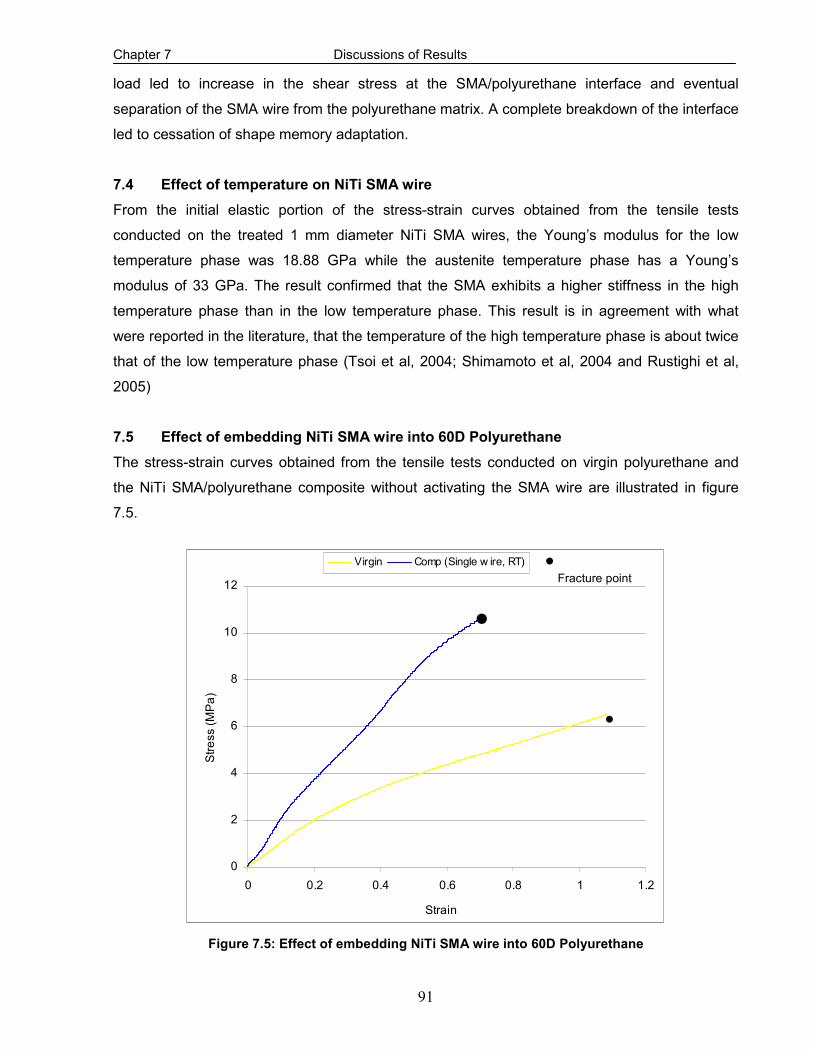
Chapter 7 Discussions of Results
91
load led to increase in the shear stress at the SMA/polyurethane interface and eventual
separation of the SMA wire from the polyurethane matrix. A complete breakdown of the interface
led to cessation of shape memory adaptation.
7.4 Effect of temperature on NiTi SMA wire
From the initial elastic portion of the stress-strain curves obtained from the tensile tests
conducted on the treated 1 mm diameter NiTi SMA wires, the Young’s modulus for the low
temperature phase was 18.88 GPa while the austenite temperature phase has a Young’s
modulus of 33 GPa. The result confirmed that the SMA exhibits a higher stiffness in the high
temperature phase than in the low temperature phase. This result is in agreement with what
were reported in the literature, that the temperature of the high temperature phase is about twice
that of the low temperature phase (Tsoi et al, 2004; Shimamoto et al, 2004 and Rustighi et al,
2005)
7.5 Effect of embedding NiTi SMA wire into 60D Polyurethane
The stress-strain curves obtained from the tensile tests conducted on virgin polyurethane and
the NiTi SMA/polyurethane composite without activating the SMA wire are illustrated in figure
7.5.
0
2
4
6
8
10
12
0 0.2 0.4 0.6 0.8 1 1.2
Strain
Stress (MPa)
Virgin Comp (Single w ire, RT)
Figure 7.5: Effect of embedding NiTi SMA wire into 60D Polyurethane
·
· ·Fracture point

Chapter 7 Discussions of Results
92
It is evident that the failure of the specimens was brittle in nature as there is no considerable
plastic deformation before fracture occurred. This suggests that the presence of the NiTi SMA
wire which although possesses high ductility, did not affect the brittle nature of the thermosetting
plastic polyurethane (Zhang et al 2007). However, it is obvious from the curves that the NiTi
SMA/polyurethane composite offers more resistance to load than virgin polyurethane. A large
residual compressive stress remained in the SMA/polyurethane matrix due to the 3% pre-strain
level of the embedded SMA wire. This residual compressive stress, on one hand, is helpful for
improving the tensile strength of the composite. But on the other hand, it will exert a large shear
stress at the interface between the SMA wires and the matrix, thus making the interface more
susceptible to debonding. The elastic modulus for the virgin polyurethane was 10 MPa and for
the SMA composite in which the embedded SMA wire was not activated, the elastic modulus
was 30 MPa. This result shows the contribution of NiTi SMA implant to increasing the stiffness of
the beam. This result indicates the effectiveness of SMA for passive applications and it conforms
to what has been reported in the literature.
7.6 Effect of volume fraction NiTi SMA wire on SMA based Composites
Figure 7.6 illustrates the effect of volume fraction of the SMA in the SMA based composites. The
non-smoothness of the curve for composite with double implanted NiTi SMA wires is attributable
0
2
4
6
8
10
12
14
16
0 0.1 0.2 0.3 0.4 0.5 0.6 0.7 0.8
Strain
Stress (MPa)
Comp (Single w ire, RT) Comp (double w ire, RT)
Figure 7.6: Effect of NiTi SMA wire volume fraction on SMA/Polyurethane composites
· · ·Fracture point

Chapter 7 Discussions of Results
93
to the different interfacial strengths that existed between the two SMA wires and the host matrix
which might be due to manufacturing imperfections. This might also be responsible for the
apparent lower level of stress values of the composite with double wire as compared with the
composite with a single wire at the initial stage of loading. However, as the load increased, it
could be seen that increasing the number of the SMA wires, increased the resistance to load.
The Young’s modulus for the composite with one wire was 30 MPa while the Young’s modulus
for the composite with double wires was 40 MPa. Their respective ultimate strengths were 10.67
MPa and 14.38 MPa. The enhancement of Young’s modulus of SMA based composite by
increasing the volume fraction of the implanted SMA as reported in the literature (Tsai and Chen,
2002; Mei et al, 2007) is thus confirmed.
7.7 Effect of Activation of NiTi SMA wire Embedded into SMA based Composites
Figure 7.7 illustrates the effect of temperature on the NiTi SMA/Polyurethane composite.
According to the literature (Tsoi et al, 2004; Shimamoto et al, 2004 and Rustighi et al, 2005), it
was expected that an activated SMA wire will utilize its characteristic advantage of high stiffness
in the high temperature phase to increase the deformation resistance and hence overall
improved mechanical property of the SMA based composite, but the result of this experimental
investigation revealed that this was not entirely true.
It could be seen from the curves that the relative advantage of activating the SMA was only
manifested at the initial stage of loading, but as the loading progressed, the resistance of the
SMA/polyurethane which had its implanted SMA wire activated reduced. Upon activating the
SMA wire, the constraint provided by the host matrix will prevent the SMA from reverting to its
un-deformed length. This hindrance to recovery of the recoverable deformation led to the
generation of recovery force which produces shear stress at the SMA wire- polyurethane
interface. The generated shear stress reduced the interfacial cohesion and eventually resulted in
debonding.
Table 7.1 gives a comparison of the properties of virgin polyurethane and SMA/polyurethane
composites with inactivated SMA wires for different volume fractions, and SMA/polyurethane
composite with activated SMA wire. The average values of the stress and strain data obtained
from the tensile tests were plotted with Microsoft Excel. A best line was fitted into the linear
portion of the stress versus strain graph, and the slope of the graph was obtained as the
Young’s modulus. This procedure was utilized to obtain the respective Young’s modulus for the
virgin polyurethane and the SMA/polyurethane composites. The relatively low mechanical

Chapter 7 Discussions of Results
94
properties of the SMA composite at an elevated temperature were as stated before due to
debonding and temperature sensitivity of the polymeric host.
0
2
4
6
8
10
12
0 0.2 0.4 0.6 0.8 1 1.2
Strain
Stress (MPa)
Virgin Comp (Single w ire, RT) Comp (Single w ire, ET)
Figure 7.7: Effect of temperature on SMA/polyurethane composites
Table 7.1: Properties of virgin 60D Polyurethane and SMA/polyurethane composites
Fracture Load (N)
Elongation at Break (mm)
Young’s Modulus (MPa)
Ultimate Tensile Strength (MPa)
Virgin Polyurethane
488.5 65.1 20 6.51
SMA/Polyurethane (single wire, without activation)
800 42.38 30 10.67
SMA/Polyurethane (double wire, without activation)
1078,8 42.8 40 14.38
SMA/Polyurethane (single wire, with activation)
236.5 26.6 20 3.15
· ·
·
·Fracture point

Chapter 7 Discussions of Results
95
7.8 Effects of NiTi SMA wire on deformation of SMA/polyurethane Composite Beams
Figure 7.8 shows the curves of bending load versus strain for the virgin polyurethane beam,
SMA/polyurethane beam with inactivated NiTi SMA wire and SMA/polyurethane beam with
activated NiTi SMA wire. It is evident from the curves that implanting NiTi SMA wire into the
polyurethane beam results in overall improved stiffness when the SMA is not activated. This
result conforms to the result that was obtained from the tensile test. Also, it could be seen that
the SMA/polyurethane beam with activated SMA wire offered more resistance to the bending
load than the SMA/polyurethane beam without activation as well as virgin polyurethane beam
but this trend was for a limited time frame (i.e. at the initial stage of loading). However, as the
loading continued, the resistance to load decreased owing to the temperature sensitivity of the
polyurethane host which resulted in the separation of the SMA wire from the matrix.
The negative strain recorded at the initial stage of loading the SMA/polyurethane beam which
had its SMA wire activated was due to the manifestation of the SME. Upon activation, the SMA
contracted so as to revert to its initial un-deformed length. This brought about the generation of
recovery stress owing to the constraint provided by the matrix and hence negative strain. This
result demonstrates the ability of the SMA to gain control of composite structure behaviour when
utilized for ASET (active strain energy tuning).
0
10
20
30
40
50
60
70
-0.0015 -0.001 -0.0005 0 0.0005 0.001 0.0015 0.002
Strain
Bending load (N)
Virgin Composite (RT) Composite (ET)
Figure 7.8: Effects of NiTi SMAs on deformation of SMA/polyurethane composite beams

Chapter 7 Discussions of Results
96
As the loading continued, the merit of activating the embedded SMA was short-lived by
debonding. This led to a drastic reduction in the resistance offered to the bending load. Figure
7.8 also shows the effectiveness of the SMA within a limited low range of bending load and
before debonding occurred. Again, it is evident that as the test progressed, the property of the
composite beam which had its SMA wire activated worsens drastically due to debonding.
7.9 Effects of NiTi SMA wire on deflection of SMA/polyurethane Composite Beams
The graph of bending load versus deflection of the virgin polyurethane and SMA based
composite beams is illustrated in figure 7.9. Table 7.2 shows the respective deflections, at a
specific point along the length of the beam and under various loads, for the virgin polyurethane
and SMA based composite beams. The point of interest considered was located at a distance of
30 mm from the left hand support (figure 7.10).
Table 7.2: Effects of NiTi SMA wire on deflection of SMA/polyurethane beams
Type of beam
Deflection (mm) under a bending load
of 5 N
Deflection (mm) under a bending load
of 10 N
Deflection (mm) under a bending load
of 15 N
Deflection (mm) under a bending load
of 20 N
Deflection (mm) under a bending load of 25 N
Virgin Polyurethane
1.03 1.91 2.97 3.95 4.89
SMA/Polyurethane (single wire, without activation)
0.81 1.13 1.50 1.75 2.05
SMA/Polyurethane (single wire, with activation)
0.39 0.9 1.49 2.20 3.57
The result shows that for a particular load, the deflection of the virgin beam is the highest while
the composite beam which had its SMA wire activated has the least deflection before debonding
occurred. From figure 7.9, it is evident that the activation of the embedded NiTi SMA wire
considerably increased the stiffness of the composite beam at the initial stage of loading. This
result conforms to what the literature reported. That is, the SMA wire in its high temperature
phase enhanced the resistance to the deflection of the SMA based composite material. This
trend continued until a load of approximately 15 N when it becomes less stiff than the composite
with inactivated SMA wire but still stiffer than the beam without SMA wire implant. Also from
figure 7.9, it could be seen that the deflection of the virgin beam varies linearly with the bending
load.

Chapter 7 Discussions of Results
97
-5
0
5
10
15
20
25
30
0 1 2 3 4 5 6
Deflection Under Load (mm)
Bending Load (N)
Virgin Composite (RT) Composite (ET)
Figure 7.9: Effects of NiTi SMAs on deflection of SMA/polyurethane composite beams
Regarding the SMA/polyurethane beams, their deflection deviated from linearity owing to the
non-linearity in the behaviour of SMA wires, due to pseudoelasticity and SME. In the case of the
beam which had its wire activated, the sudden drop in the bending load was due to the reduction
of the interfacial strength between the SMA and the polymeric host.
The reduction in the interfacial bond initiated debonding. However, despite the adverse effects of
debonding and the temperature sensitivity of the polymeric host, the activated SMA based
composite still offered more resistance to the bending load than the virgin polyurethane beam.

Chapter 7 Discussions of Results
98
7.10 Comparisons of Bending Stiffness of Virgin Polyurethane and SMA/polyurethane
Composite Beams
Figure 7.10: Idealization of the four point bending test
The deflection y, of the beam shown in figure 7.10 at specific points ax ≤≤0 from the left hand
support A is given by:
EI
xLaaxy
6
)33( 22 +−Ρ−= ax ≤≤0 (7.1)
The derivation of equation 7.1 is in appendix F. The length of the beam under consideration
is a3 in which a is 30 mm, therefore the deflection of the beam at a point D which is at distance
a from the left hand support yields:
EI
ay
6
5 3Ρ= (7.2)
Rearranging equation 7.2, we have
ya
EI
=Ρ
35
6 (7.3)
where
Ρ is the bending load
y is the deflection of the beam at a distance a from the left hand support
EI is the bending stiffness of the beam
Defining 35
6
a
EIk = , equation 7.3 becomes
P
A
B
P
a
a
a
x
y
D

Chapter 7 Discussions of Results
99
ky=Ρ (7.4)
The slope of the graph of bending load against the deflection will give k . The respective value of
k obtained for the three beams under consideration is given in table 7.3
Table 7.3: Slope of the graph of bending load vs. deflection
Type of beam k
Virgin Polyurethane
4995
SMA composite beam with inactivated SMA
6666
SMA composite beam with activated SMA
10262
Utilizing the values of k in table 7.3, the respective bending stiffness can be obtained as follows:
For virgin polyurethane beam:
35
6
a
EI= 4995 (7.5)
But ma 03.0= , therefore from equation 7.5, we have
6
54995)03.0( 3 ××=EI = 0.1124 Nm2 (7.6)
Following from above, for SMA/polyurethane composite beam with inactivated wire, we have
6
56666)03.0( 3 ××=EI = 0.1500 Nm2 (7.7)
And for SMA/polyurethane composite beam with activated wire, we have
6
510262)03.0( 3 ××=EI = 0.2309 Nm2 (7.8)

Chapter 7 Discussions of Results
100
The respective bending stiffness is presented in Table 7.4.
Table 7.4: Comparison of the bending stiffness
Type of beam Bending Stiffness (EI)
Nm2
Virgin Polyurethane beam 0.1224
SMA composite beam with inactivated SMA
0.1500
SMA composite beam with activated SMA
0.2309
The results presented in table 7.4 confirm the significant improvement in the stiffness of the SMA
based composite beams over the virgin polyurethane beam.

Chapter 8 Conclusions and Recommendations
101
CHAPTER EIGHT
CONCLUSIONS AND RECOMMENDATIONS
8.1 Conclusions
The improvement in the mechanical property and the behaviour of 60D polyurethane upon
integration NiTi SMA wires were investigated at room and elevated temperatures. It was found
that heat treatment by ageing results to improvement in mechanical properties and homogenous
behaviour of the SMA wires. Therefore, prior to embedding the NiTi SMA wires into the
polyurethane host, they were aged at 250oC. The unusual properties and behaviours of the NiTi
SMAs, when embedded into or bonded onto host matrix, can only be exhibited if they are made
to suffer permissible recoverable deformation before they are embedded or bonded into the
polymeric host. Thus, all the implanted SMA wires were successfully pre-strained by 3%.
It was found that the vacuum casting process of manufacturing utilized for casting the
composites and virgin components was suitable owing to its merit highlighted in section 6.2.
The choice of the thermosetting polyurethane matrix was that its curing does not have a
negative impact on the actuating potential of the NiTi wires.
Polyurethane being a thermosetting plastic is brittle in nature and this was confirmed by the
tensile test. Nevertheless, the integration of the SMA wire into it ought to have theoretically
increased the ductility of the resulting composite; however the experimental result was contrary.
Interestingly, the elongation at break of the SMA/polyurethane composite was less than that of
the virgin polyurethane. The possible reason would be low volume fraction of the SMA wire and
perhaps insufficient interfacial strength. Upon activating the SMA wire, owing to the generation
of recovery force and the accompanied shear stress at the SMA-polyurethane interface, the
debonding load at elevated temperature was comparatively low. However, integration of the
NiTi SMA wire into the polyurethane results to an increase in the elastic modulus, ultimate
tensile strength and bending stiffness. An increase in the volume fraction of the pre-strained NiTi
SMA in its martensitic phase significantly improves the mechanical property of the
SMA/polyurethane composites at both room and elevated temperatures. But nevertheless, the
improvement in properties of the composites which have the embedded SMA wires activated is
limited by degradation of the interfacial bond between the SMA and the polyurethane matrix as
the temperature increases.

Chapter 8 Conclusions and Recommendations
102
It was established that embedding SMA wire into polymeric host significantly improves the
stiffness of the resulting SMA/polyurethane composites at both room and elevated temperatures.
It was found that increasing the volume fraction of the SMA wires results to increase in stiffness.
Since the stiffness of the composite is directly related to the resistance it can offer to applied
load amongst others, it can therefore be concluded that the integration of the SMA wire into the
polymeric composites is effective in the reduction of the deflection of a loaded SMA based
composite beam. The four point bending test results showed that the embedded SMA wires gain
structural control over the polymeric composite upon activation. Therefore, embedding SMA into
polymeric composite is an effective way to actively control the position and shape of the SMA
based composite.
In summary, it is concluded that:
• The manufacturing of the virgin specimens from 60D polyurethane and the
SMA/polyurethane composites by vacuum casting process was successful
• Ageing and prestraining enhanced the properties of the embedded NiTi SMAs and
lowered the transformation temperatures
• The elastic modulus of the NiTi SMA in the high temperature austenite phase is higher
than the elastic modulus of the NiTi SMA in the low temperature martensite phase
• The pull out (debonding) load vis-à-vis the stress when the SMA wire is inactivated is
higher than when the SMA is activated
• Embedded SMA increases the elastic modulus, ultimate tensile strength and bending
stiffness of the SMA/polyurethane composite
• High temperature degrades the interfacial adhesion between the SMA and the
polyurethane host matrix
• Increase in the volume fraction of the SMA leads to an increase in the mechanical
properties of the SMA/polyurethane composite
• Embedded SMA wires upon activation gain structural control of the composite beam
8.2 Recommendations
The embedded SMA wires have the propensity to contract several percent in strain upon
heating, SMA based composites are therefore more susceptible to interfacial debonding than
any other composite. A requirement for adaptation is that the SMA/host interface must be of
sufficient high quality to sustain both an elevated temperature and applied SMA constrained
recovery force. Since the integrity and performance of the fibre reinforced composites is a

Chapter 8 Conclusions and Recommendations
103
function of cohesive adherence between the fibre reinforcements and the host matrix, surface
treatment (e.g. by sandblasting) of the NiTi wires will be necessary to facilitate improved
interfacial bond strength between the NiTi wires and their host matrices. Investigation of the
pullout load with spiral or twisted SMA wires is recommended to ascertain its improvement or
otherwise over the linear (or straight) SMA wires.
Indubitably, the pre-strain level of the embedded SMA wires significantly affects the behaviour of
SMA composite. The maximum contracting strain that can be generated by the SMA based
composite during heating before failure of the interface, decreases with increasing pre-strain. It
is widely accepted that a higher pre-strain can provide a higher ultimate recovery stress
however, a high pre-strain reduces the reliability of the interface significantly due to generation of
excessive shear stress at the interface. Therefore, a small pre-strain level is necessary to
produce a reliable SMA composite. This implies that a compromise is necessary between
mechanical properties and reliability of SMA composite when selecting the pre-strain level of the
embedded SMA wires. Consequently, if the recovery stress of a composite needs to be tailored,
the best way should be to increase the volume fraction of the SMA rather than increasing the
pre-strain of the SMA.
Increasing the volume fraction of the SMA wires can be achieved by either increasing the
number of the SMA wires or their thicknesses. 1mm diameter SMA wires were utilized for this
research activity, therefore in order to avoid the complexities of activation of the SMA wires; it is
recommended that bigger diameter from 2 mm upwards can be utilized. The direct heating
method for tests at elevated temperatures was based on the assumption that heat diffusion
between the SMA wire surface and the ambient temperature was negligible but in reality, heat
lost to the surroundings can not be completely averted. Therefore, since temperature is a
necessary concern, a better method to minimise heat dispersion on the wire surface should be
investigated.
The functional properties of SMA-composites are directly related to the constraints provided by
the composite matrix. The higher the elastic modulus of the composite matrix, the larger the
amount of constraints. The elastic modulus of the polymer utilized for this research is
comparatively low, thus its practical applications are limited. It is recommended that, the
influence of SMA on high elastic modulus materials be investigated. The influence of additional
reinforcing fibres: widely used glass fibre/ epoxy composites will be more suitable than just pure
epoxy. Since most of the composite materials being envisaged for practical applications are

Chapter 8 Conclusions and Recommendations
104
more likely to be utilized in high temperature environment, the working temperature of the SMA
based composite should be well below the glass transition temperature of the polymeric host in
order to avoid the latter’s softening.

References
105
REFERENCES
Aboudi, J. 1997. The response of shape memory alloy composites. Smart Mater. Struct., 6:1 - 9. Armstrong, W.D. & Lilholt, H. 2000. The time dependant, super-viscoelastic behaviour of NiTi shape memory alloy fiber reinforced polymer matrix composites. Materials Science and Engineering, B68:149-155. Azar, M.T., Sutapun, B. & Huff, M. 1999. Applications of TiNi thin film shape memory alloys in micro-epto-electro-mechanical systems. Sensors and Actuators, 77:34-38. Balta, J.A., Bosia, F., Michaud, V., Dunkel, G., Botsis, J. & Manson, J.A. 2005. Smart composites with embedded shape memory alloy actuators and fibre bragg grating sensors: activation and control. Smart Mater. Struct., 14:457-465. Baz A., Imam K. & McJoy, K. 1990. Active vibration control of flexible beams using shape memory actuators. J. Sound Vib., 140:437-456. Benham, R.J., Crawford, R.J. & Armstrong, C.G. 1996. Mechanics of engineering materials. 2nd ed. London: Pentice Hall. Besseghini, S., Villa, E. & Tuissi, A. 1999. Ni – Ti – Hf shape memory alloy: effect of aging and thermal cycling. Materials Science and Engineering, A 273- 275:390-394. Bhaumik, S.K., Ramaiah, V. & Saikrishna, C.N. 2006. Effects of thermo-mechanical cycling on the strain response of Ni-Ti-Cu shape memory alloy wire actuator. Materials Science and Engineering, A 428:217-224. Brinson, L.C. 1993. One-dimensional constitutive behaviour of shape memory alloys: Thermomechanical derivation with non-constant material functions and redefined martensite internal variable. J. Intell. Mater. Syst. Struct., 4:229-242. Bruck, H.A. & Moore, C.L. 2002. A fundamental investigation into large strain recovery of one-way shape memory alloy wires embedded in flexible polyurethanes. Smart Mater. Struct., 11:130-139. Cho, M. & Kim, S. 2005. Structural morphing using two-way shape memory effect of SMA. International Journal of Solids and Structures, 42: 1759-1776. Cui, L., Li, J. & Zheng, Y. 2006. Martensitic transformations and thermal expansion behaviours of structural heterogeneous NiTi alloys. Materials Science and Engineering, A 438-440: 567-570. Davoodi, H., Noori, M.N., Hou Z. & Marioni, A. 1997. Application of shape memory alloys in vibration control. Proc. 16th Can. Congr. Applied Mechanics, CANCAM (Quebec), 1997. Dolci, M. & Cardone, D. 2001. Mechanical behaviour of shape memory alloys for seismic

References
106
applications 2: Austenitic NiTi wires subjected to tension. International Journal of Mechanical Sciences, 43:2656-2677. Duerig, T.W. & Zadno, R. 1990. An engineer’s perspective of pseudoelasticity in engineering aspects of shape memory alloys. Editors: Deurig, T.W., Melton, K.N., Stockel, D. and Wayman, C.M. Butterworth-Heinemann. Duerig, T.W., Melton., K.N., Stockel, D. & Wayman, C.M. 1990. Engineering aspects of shape memory alloys. Boston:Butterworth-Heinemann. Duerig, T.W., Pelton, A. & Stockel, D. 1999. An overview of Nitinol medical applications. Materials Science and Engineering, A 273-275:149-160. Gabriel, K.J., Trimmer, W.S.N. & Walker, J. A. 1988. A micro rotary actuator using shape memory alloys. Sensors and Actuators, 15:95-102. Gandhi, F. & Wolons, D. 1999. Characterization of the pseudoelastic damping behaviour of shape memory alloy wires using complex modulus. Smart Materials and Structures, 8:49-56. Gangbing, S., Brian, K. & Brij, N.A. 2000. Active position control of a shape memory alloy wire actuated composite beam. Smart Mater. Struct., 9:711-716. Gere, J.M. & Timoshenko, S.P. 1999. Mechanics of materials. 4th ed. London: Stanley Thornes. Gordaninejad, F., Ghazavi, A., Tabandeh, N. & Ghomshei, M.M. 2005. Nonlinear transient response of a thick composite beam with shape memory alloy layers. Composites: Part B, 36:9-24. Groover, M.P. 2002. Fundamentals of modern manufacturing-materials, processes, and systems. 2nd ed. USA: John Willey & Sons. Heyliger, P.R. & Reddy, J.N. 1988. A higher order beam finite element for bending and vibration problems. J Sound Vib., 126(2):309-326 Hurlebans, S. & Gaul, L. 2006. Smart structure dynamics. Mechanical Systems and Signal Processing, 20:225-281. Kim, J.H & Roh, J.H.2003. Adaptability of hybrid smart composite plate under low velocity impact. Composites: Part B, 34:117-125. Kim, J.H., Park, J.S. & Moon, S.H. 2004. Vibration of thermally post-buckled composite plates embedded with shape memory alloy fibres. Composite Structures, 63:179-188. Lau, K., Poon, C., & Zhou, L. 2005. Design of pull-out stresses for prestrained SMA wire/polymer hybrid composites. Composites Part B., 36: 25-31. Lau, K.T., Ling, H.Y. & Zhou L.M. 2004. Low Velocity impact on shape memory alloy stitched composite plates. Smart Mater. Struct., 13:364-370. Lau, K.T., Zhou, L.M. & Tao, X.M. 2002. Control of natural frequencies of a clamped-clamped composite beam with embedded shape memory alloy wires. Composite structures, 58:39-47.

References
107
Lee, J.J. & Choi, S. 1998. The shape control of a composite beam with embedded shape memory alloy wire actuators. Smart Mater. Struct., 7:759-770. Lee, J.J. & Lee, H.J. 2000. A numerical analysis of the buckling and postbuckling behaviour of laminated composite shells with embedded shape memory alloy wire actuators. Smart Mater. Struct., 9:780-787. Lexcellent, C., Leclercq, B., Gabry, B. & Bourbon, G. 2000. The two-way shape memory effect of shape memory alloys: an experimental study and a phenomenological mode. International Journal of Plasticity, 16:1155-1168. Liang, C. & Rogers, C. A. 1990. One-dimensional thermomechanical constitutive relations for shape memory materials. J. Intell. Mater. Syst. Struct., 1:207-234. Liang, C. & Rogers, C.A. 1989. Behaviour of shape memory alloy reinforced composite plates apart I: model formulations and control concepts. Am. Inst. Aeronaut, Astronaut, 89-1389-CP: 2011-2017. Liu, Y., Xie, Z. & Humbeeck, J.V. 1999. Cyclic deformation of NiTi shape memory alloys. Materials Science and Engineering, A 273-275; 673-678. Loughlan J., Thompson S.P. & Smith H., 2002. Buckling control using embedded shape memory actuators and the utilization of smart technology in future aerospace platforms. Composite Structures, 58:319-347. Lu, X.L., Zhao, L.C. & Cai, W. 2005. Damping behaviour of TiNi- based shape memory alloys. Materials Science and Engineering, A 394:78-82. Luo, Y., Okuyama, T., Takagi, T., Kamiyana, T., Nishi, K. & Yambe, T. 2005. Thermal control of shape memory alloy artificial anal sphincters for complete implantation. Smart mater. Struct., 14:29-35. Mei, C., Duan, B., Tawfik, M., Goek, S.N. & Ro, J.J. Vibration of laminated composite plates embedded with shape memory alloy at elevated temperatures. [email protected] [4th May, 2007]. Meo, M., Antonucci, E., Duclaux, P. & Giordano, M. 2005. Finite element simulation of low velocity impact on shape memory alloy composite plates. Composite Structures, 71:337-342. Morgan, N.B. 2004. Medical shape memory alloy applications-the market and its products. Materials Science and Engineering, A 378:16-23. Mukhawana, D. & Philander, O. 2006. Effects of thermo-mechanical cycling and aging on quasi-plastic material response exhibited by NiTi shape memory alloys. SACAM06, 16-18 January, 2006. Nasser, S.N. & Guo, W.G. 2006. Superelastic and Cyclic Response of NiTi SMA at Various Strain Rates and Temperatures. Mechanics of materials, 38:463-474. Ni, Q.Q., Zhang, R.X., Masuda, A., Yamamura, T. & Iwamoto, M. 2006. Vibration characteristics of laminated composite plates with embedded shape memory alloys. Composite Structures, 74:389-398.

References
108
Ni, Q.Q., Zhang, R.X., Natsuki, T. & Iwamoto, M. 2007. Stiffness and vibration of SMA/ER 3 composites with shape memory alloy short fibres. Composite Structures, 79:501-507. Paine, J.S.N. & Rogers, C.A., 1993. Characterization of interfacial shear strength between shape memory alloy actuators and host composite material in adaptive composite material systems, ASME, AD-35:63-70. Parthenios, J., Psarras, G. C., & Galiotis, C. 2001. Adaptive composites incorporating shape memory alloy wires. Part 2: development of internal recovery stresses as a function of activation temperature, Composites: Part A, 32:1735-1747. Su, Z., Mai, H., Lu, M. & Ye, L. 1999. Thermo-mechanical behaviour of shape memory alloy reinforced composite laminate (Ni-Ti/glass-fibre/epoxy). Composite Structures, 47:705-710 Patoor, E., Lagoudas, D.C., Entchev, P.B., Brinson, L.C. & Gao, X. 2006. Shape memory alloys, Part I: general properties and modelling single crystals. Mechanics of Materials, 38:391-429. Pemble, M. & Towe, B.C. 1999. A miniature shape memory pinch valve. Sensors and Actuators. 77:145-148. Philander, O. 2004. The development of a computational tool for use in the design of actuator systems consisting of NiTi shape memory alloys harnessing the shape memory effect. Unpublished PhD thesis, Cape Peninsula University of Technology, Cape Town. Piedboeuf, M.C., Gauvin, R. & Thomas, M. 1998. Damping behaviour of shape memory alloys: strain amplitude, frequency and temperature effect. Journal of Sound and Vibration, 214(5):885-901. Pilkey, W. D. & Wunderlich, W. Mechanics of structures: variational and computational methods. Florida: CRS Press Qidwai M.A. & DeGiorgi, V.G. 2004. Numerical assessment of the dynamic behaviour of hybrid shape memory alloy composite. Smart Mater. Struct., 13:134-145. Qidwai, M.A. & Lagoudas D.C. 2000. On thermomechanics and transformation surfaces of polycrystalline shape memory alloy materials. International Journal of Plasticity, 16:1309-1343. Rogers, C.A, Liang, C. & Jia, J. 1991. Structural modification of simply supported laminated plates using embedded shape memory alloy fibres. Computer and Structures. 38 (5-6):569-580. Rogers, G. F. C., & Mayhew, Y. R. 1988. Engineering thermodynamics. ELBS. Longman: Hong Kong. Rstighi, E., Brennan, M.J. & Mace, B.R. 2005. A shape memory alloy adaptive tuned vibration absorber: design and implementation. Smart Mater. Struct., 14:19-28. Salsedo, F., Dario, P. & Bergamasco, M. 1990. Shape memory alloy microactuators. Sensors and Actuators, A21-A23:253-257. Schulte, K. & Fiedler, B. 1997. Photo-elastic analysis of fibre-reinforced model composite materials. Composites Science and Technology, 57:859-867.

References
109
Shimamoto, A., Ohkawara, H. & Nogata, F., 2004. Enhancement of mechanical strength by shape memory effect in TiNi fiber-reinforced composites. Engineering Fracture Mechanics, 71:737-746. Song, G., Ma, N. & Li, H.N. 2006. Applications of shape memory alloys in civil structures. Engineering Structures, 28:1266-1274. Spillman (Jr.), W.B., Sirkis, J.S. & Gardiner, P.T.1996 .Smart materials and structures: what are they [sic]? Smart mater. Struct., 8:247-254. Srinivasan, A.V. & McFarland, D.M. 2001. Smart structures-analysis and design. United Kingdom: Cambridge University Press. Stalmans, R, 2006. Adaptive hybrid composites with focus on the integration of shape memory elements. Ecole Polytechnique. Tanaka, K., Kobayashi, S. & Sato, Y. 1986. Thermomechanics of transformation pseudoelasticity and shape memory effect in alloys. Int. J. Plast, vol. 2:59-72.
Tang, C.Y., Wei, Z.G. & Lee, W.B. 1997. Design and fabrication of intelligent composites based on shape memory alloys. Journal of Materials Processing Technology, 69:68-74. Thompson S. P. & Loughlan J., 2001. Enhancing the post-buckling response of a composite panel structure utilising shape memory alloy actuators – a smart structural concept. Composite Structures, 51:21-36. Tong, H. & Wayman, C. 1974. Chracteristics temperatures and other properties of thermoelastic martensites. Acta Metall., 22:887-896. Trochu, F & Qian, Y.Y. 1997. Nonlinear finite element simulation of superelastic shape memory alloy parts. Computers and Structures: 62(5) 799-810. Tsai, X.Y. & Chen, L.W. 2002. Dynamic stability of a shape memory alloy wire reinforced composite beam. Composite Structures, vol. 56:235-241. Tsoi, K.A., Stalmans, R. & Schrooten, J. 2002. Transformational behaviour of constrained shape memory alloys. Acta Materiala, 50: 3535-3544. Tsoi, K.A., Schrooten, J. & Stalmans, R. 2004. Thermomechanical characteristics of shape memory alloys. Materials Science and Engineering, A 368: 286-298. Turner, T.L, 2000. Proceedings of the 7th international conference on recent advances in structural dynamics. The Institute of Sound and Vibration Research, University of Southampton England. Turner, T.L. 2001. Thermomechanical response of shape memory alloy hybrid composites. National Aeronautics and Space Administration. Langley research centre, Hampton, Virginia, NASA/TM-2001-210656. Uchil, J., Kumara, K.G. & Mahesh, K.K. 2002. Effect of thermal cycling on R-phase stability in a NiTi shape memory alloy’ Materials Science and Engineering, A332:25-28.

References
110
Umezaki, E. 2000. Improvement in separation of SMA from matrix in SMA embedded smart structures. Materials Science and Engineering, A332:363-369. Umezaki, E. 2006. Temperature distributions of SMA wires embedded in epoxy resin plates and heated by supplying electric current. Journal of Intelligent material Systems and Structures, 17:1115-1120. Vokoun, D., Kafka, V. & Hu, C.T. 2003. Recovery stresses generated by NiTi shape memory wires under different constraint conditions. Smart Mater Struct., 12:680-685. Wang, J.J., Omori, T., Sutou, Y., Kainuma, R. & Ishida, K. 2005. Two-way shape memory effect induced by cold-rolling in Ti-Ni and Ti-Ni-Fe alloys. Scripta Materialia, 52:311-316. Wei, Z.G., Sandstrom, R. & Miyazaki, S. 1998. Review: shape-memory materials and hybrid composites for smart systems. Journal of Materials Science, 33:3743-3762. Wei, Z.G., Tang, C.Y. & Lee, W.B. 1997. Design and fabrication of intelligent composites based on shape memory alloys. J. of Matls. Proc. Tech., 69:68-74. Williams (Jr), DC, 2003. Materials science and engineering: an introduction. London: John Willey & Sons. Yang D. 2000. Shape memory alloy and smart hybrid composites- advanced materials for the 21st century. Materials and Design, 21:503- 505. Ye, L., Mai, Y.W & Su, Z. 2004. Composite technology for 2020. Proceedings of the 4th Asian-Australian Conference on Composite materials, ACCM4. Yi, S. & Gao, S. 2003. Experimental study on the anisotropic behaviour of textured NiTi pseudoelastic shape memory alloys. Materilas Science and Engineering, A362:107-111. Yoshida, I., Ono, T. & Asai, M. 2000. Internal friction of Ti-Ni alloys. J. Alloy and Compound, 310:339-343. Zhang, R.X., Ni, Q.Q., Natsuki, T. & Iwamoto, M. 2007. Mechanical properties of composites filled with SMA particles and short fibres. Composite Structures, 79:90-96. Zhao, Y.P. & Zhang, Y. 2007. A study of composite beam with shape memory alloy arbitrarily embedded under thermal and mechanical loadings. Materials and Design, 28:1096-1115. Zheng, Y. J., Cui, L. S. & Schrooten, J. 2005. Basic design guidelines for SMA/epoxy smart composites. Materials Science and Engineering, A 390: 139-143.
Appendix A Crystal Structures for the Austenite Phase and the Martensite Phase
111
APPENDIX A: CRYSTAL STRUCTURES FOR THE AUSTENITE PHASE AND THE MARTENSITE PHASE
Figure A1: Crystal Structure for the Austenite Phase (body centred cubic lattice)
Figure A2: Crystal Structure for the Martensite Phase (simple cubic lattice)

Appendix B Pseudo elastic Effect
112
APPENDIX B: THE PSEUDO ELASTIC EFFECT
Figure B1: Schematic illustration of the pseudo-elastic effect
PQR represents the loading path while the unloading path is represented by LMN. Regarding the loading of the SMA, we have that:
At sMT > the SMA is in 100% austenite phase
At sf MTM << the SMA exists in a combination of austenite phase and martensite phase
At fMT ≤ the SMA is in 100% martensite phase
Regarding the unloading of the SMA, we have that:
At sAT < the SMA is in 100% martensite phase
At fs ATA << the SMA exists in a combination of austenite phase and martensite phase
At fAT ≥ the SMA is in 100% austenite phase
From the foregoing it is evident that a change of temperature within the range
ss ATM << induces no phase changes and that both austenite and martensite can coexist
within ff ATM << .
fM sM SA fA
Temperature (T)
Load
P
Q
R L
M
N

Appendix C Effects of Ageing and Pre-straining on NiTi SMAs
113
APPENDIX C: EFFECTS OF AGEING AND PRESTRAINING ON NiTi SMAs
Effect of Ageing on NiTi SMAs
0
200
400
600
800
1000
1200
0 0.02 0.04 0.06 0.08 0.1 0.12 0.14 0.16
Strain
Stress (
MPa)
Without ageing 250 degrees ageing temperature
Effects of ageing at 250 degrees and 3% prestrain
0
200
400
600
800
1000
1200
0 0.02 0.04 0.06 0.08 0.1 0.12 0.14 0.16
Strain
Stress (M
Pa)

Appendix C Effects of Ageing and Pre-straining on NiTi SMAs
114
Effects of ageing at 300 degrees and 3% prestrain
0
200
400
600
800
1000
1200
0 0.05 0.1 0.15 0.2
Strain
Stress (M
Pa)
Effects of ageing at 350 degrees and 3% prestrain
0
200
400
600
800
1000
1200
0 0.05 0.1 0.15 0.2
Strain
Stress (M
Pa)

Appendix C Effects of Ageing and Pre-straining on NiTi SMAs
115
Effects of ageing at 400 degress and 3% prestarin
0
200
400
600
800
1000
1200
0 0.05 0.1 0.15 0.2
Strain
Stress (M
Pa)
Effects of Ageing on NiTi SMAs
0
200
400
600
800
1000
1200
0 0.02 0.04 0.06 0.08 0.1 0.12 0.14 0.16
Strain
Stress (M
Pa)
250 300 350 400
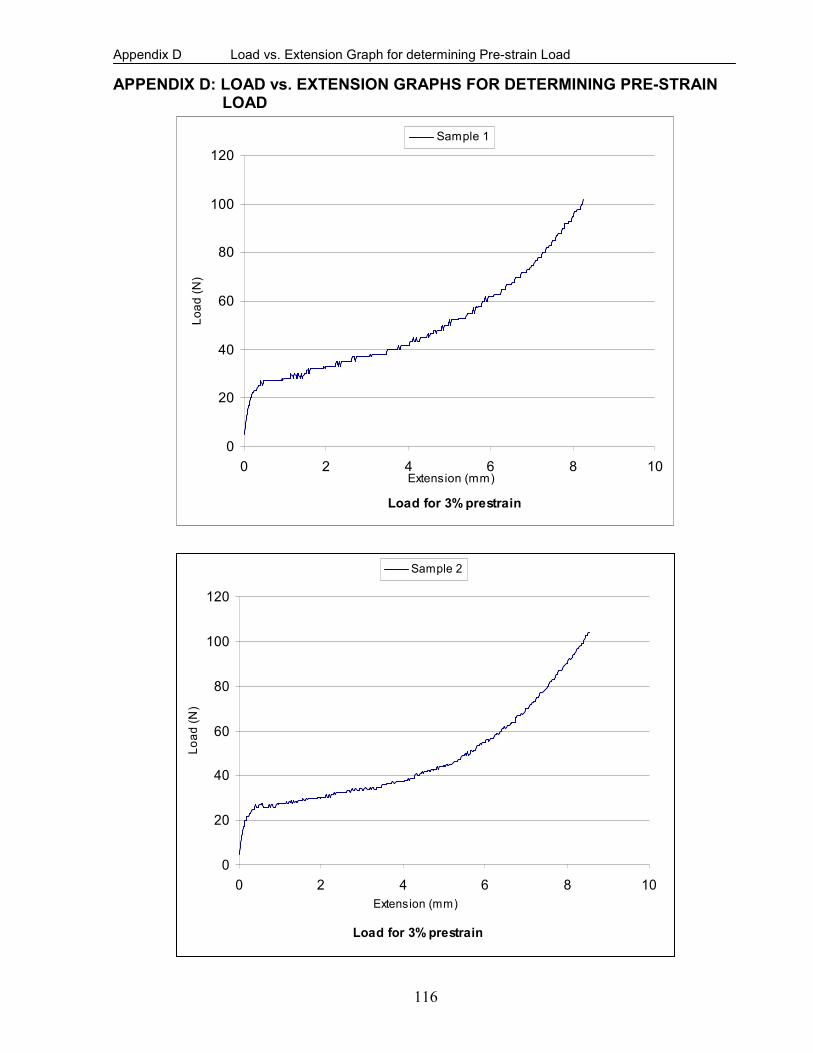
Appendix D Load vs. Extension Graph for determining Pre-strain Load
116
APPENDIX D: LOAD vs. EXTENSION GRAPHS FOR DETERMINING PRE-STRAIN LOAD
Load for 3% prestrain
0
20
40
60
80
100
120
0 2 4 6 8 10Extension (mm)
Load (N
)
Sample 1
Load for 3% prestrain
0
20
40
60
80
100
120
0 2 4 6 8 10
Extension (mm)
Load (N
)
Sample 2

Appendix D Load vs. Extension Graph for determining Pre-strain Load
117
Load for 3% prestrain
4.5 mm
55N

Appendix E Effect of Temperature on Pullout Load
118
APPENDIX E: EFFECT OF TEMPERATURE ON PULLOUT LOAD
Pull-Out Load vs Displacement (Room Temperature)
0
20
40
60
80
100
120
140
0 5 10 15 20 25
Displacement (mm)
Pull-O
ut Load (N
)
Sample 1 Sample 2
Pull-Out Load vs Displacement (Elevated Temperature)
0
10
20
30
40
50
60
70
80
0 5 10 15 20 25 30
Displacement (mm)
Pull-
Out Load (N
)
sample 1 Sample 2
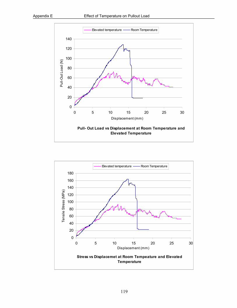
Appendix E Effect of Temperature on Pullout Load
119
Pull- Out Load vs Displacement at Room Temperature and
Elevated Temperature
0
20
40
60
80
100
120
140
0 5 10 15 20 25 30
Displacement (mm)
Pull-O
ut Load (N
)
Elevated temperature Room Temperature
Stress vs Displacemet at Room Tempeature and Elevated
Temperature
0
20
40
60
80
100
120
140
160
180
0 5 10 15 20 25 30
Displacement (mm)
Tensile S
tress (M
Pa)
Elevated temperature Room Temperature

Appendix F Development of Equation for Deflection of Beam
120
APPENDIX F: DEVELOPMENT OF EQUATION FOR DEFLECTION OF BEAM
Figure F1: Loading diagram for a beam
The bending moment, )(xM at any point along the beam is given by:
)(2
2
xMdx
ydEI −= (F1)
Considering the equilibrium of the beam, we have:
PRRBA2=+ (F2)
Taking moment of all the forces about the right hand supportB , we have:
PaaLPLRA
+−= )( (F3)
Simplifying equation F3, we have:
PRA= (F4)
RA
RB
L
A
B
P
P
a
a
a
x
y
P
A
B
P
a
a
a
x
y

Appendix F Development of Equation for Deflection of Beam
121
Due to symmetry of loading, only the left half portion of the beam will be considered. The
moment )(xM at any point ax ≤≤0 along the beam becomes:
PxxRxMA==)( (F5)
Also, the moment )(xM at any point 2
Lxa ≤≤ along the beam is given by:
)()( axppxxM −+−= (F6)
Utilizing equations F5 and F6 the moment )(xM at any point 2
0L
x ≤≤ along the beam can be
written as:
][)( axppxxM −+−= (F7)
where for ax < , 0][ =− ax
Therefore, substituting equation F7 into equation F1, we have:
][2
2
axPPxdx
ydEI −−= (F8)
Integrating equation F8, we have:
1
22 ][22
CaxP
xP
dx
dyEI +−−= (F9)
Integrating equation F9, we have:
21
33 ][66
CxCaxP
xP
EIy ++−−= (F10)
When 0=x , 0=y and 0][ =− ax , therefore, 02=C in equation F10, thus

Appendix F Development of Equation for Deflection of Beam
122
xCaxP
xP
EIy1
33 ][66
+−−= (F11)
Due to symmetry of loading, the slope of the deflection at the midpoint of the beam will be zero,
i.e. at 2
Lx = , 0=
dx
dy. Utilizing this condition in equation F9 , we have:
1
22
122220 C
aLPLP+
−
−
= (F12)
Solving equation F12 for 1C , we have:
)(2
2
1Laa
PC −= (F13)
Substituting equation F13 into equation F11, we have:
)(2
][66
233 LaaxP
axP
xP
EIy −+−−= (F14)
For ax < , 0][ 3 =− ax , equation F14 becomes:
)(26
23 LaaxP
xP
EIy −+= (F15)
Simplifying equation F15 and solving for the deflection y , we have:
EI
xLaaPxy
6
33( 22 +−= (F16)
June 2008