investigation on performance of li(ni0.5co0.2mn0.3)1...
TRANSCRIPT
CERAMICSINTERNATIONAL
Available online at www.sciencedirect.com
http://dx.doi.org/0272-8842/& 20
nCorrespondinHarbin InstituteChina. Tel.: þ8
E-mail addre
(2015) 9069–9077
Ceramics International 41 www.elsevier.com/locate/ceramintInvestigation on performance of Li(Ni0.5Co0.2Mn0.3)1�xTixO2 cathodematerials for lithium-ion battery
Yin Zhanga, Zhen-Bo Wanga,n, Jie Leia, Fang-Fei Lib, Jin Wuc, Xiao-Gang Zhangc,Fu-Da Yua, Ke Kea
aSchool of Chemical Engineering and Technology, Harbin Institute of Technology, No. 92 West-Da Zhi Street, Harbin 150001 ChinabSchool of Electrical Engineering and Automation, Harbin Institute of Technology, Harbin 150001, China
cXi’an Huijie Industrial Co., Ltd., Xi’an 710116 China
Received 19 March 2015; received in revised form 25 March 2015; accepted 27 March 2015Available online 6 April 2015
Abstract
In order to investigate the influences of modification on industrial-grade cathode materials, layered Ti-doped Li(Ni0.5Co0.2Mn0.3)1�xTixO2
cathode materials have been synthesized via a simple solid state method using industrial raw materials in bulk scale (410 kg) in this work. X-raydiffraction (XRD), Rietveld refinement, scanning electron microscopy (SEM), energy dispersive spectrometer (EDS) mapping, particle sizedistribution and electrochemical tests including cyclic voltammetry (CV) and electrical impedance spectroscopy (EIS) have been used tocharacterize electrochemical performance of industrial-grade cathode materials. The results of XRD, SEM and EDS mapping characterizationindicate that all the modified cathode materials with their Ni, Co and Mn components doped by titanium keep a typical α-NaFeO2 layeredstructure with R-3m space group and titanium atoms are uniformly distributed in all series of Ti-doped materials as prepared. Electrochemicalcharacterization confirms that the material of 0.2% Ti doping has the best cycling performance and the least capacity loss because of its bestcation ordering figured by Rietveld refinement of XRD. The initial discharge capacity of 0.2% Ti doping material achieves 185.0 mA h/g at 1 Cbetween 2.8 and 4.6 V. Additionally, the capacity retention maintains at 93.4% after 200 charge–discharge cycles.& 2015 Elsevier Ltd and Techna Group S.r.l. All rights reserved.
Keywords: Lithium-ion battery; Cathode material; Ti-doped; XRD Rietveld refinement
1. Introduction
Lithium-ion batteries are widely used throughout manydomains such as 3C products, including computer, commu-nication and consumer electronics due to its high energydensity, long cycle life, small size, no memory effect, lowself discharge and environment-friendly character [1–5].LiCoO2 (LCO) is the main cathode material of currentcommercial lithium-ion battery [6–8]. However, high costand lack of resource of Co element limit the application fields
10.1016/j.ceramint.2015.03.28015 Elsevier Ltd and Techna Group S.r.l. All rights reserved.
g author at: School of Chemical Engineering and Technology,of Technology, No. 92 West-Da Zhi Street, Harbin 1500016 451 86417853; fax: þ86 451 86418616.ss: [email protected] (Z.-B. Wang).
of lithium-ion batteries. Besides, LiNiO2 (LNO) and LiMnO2
(LMO) cathode materials, as the Co-free alternatives, stillsuffer from their own imperfection. LNO is difficult to besynthesized [9], and its unstable structure leads to rapidcapacity fading and weak thermal stability [10]. LMO iscomposed of micro-sized particles reported in majority ofexisting literatures, and its capacity and cycle stability areunsatisfied [11,12]. To this end, it renders researchers to makeefforts to develop alternatives. LiNi1/3Co1/3Mn1/3O2 (NCM), anovel kind of layered structure cathode material using inlithium-ion battery, which has all advantages of LCO, LNOand LMO, has been developed in 2001 by Ohzuku [13].NCM, in part, is a promising energy material on account of
its high specific capacity and a moderately high rate perfor-mance with stable structure and good safety property, which

Y. Zhang et al. / Ceramics International 41 (2015) 9069–90779070
may take the place of LCO in the future. Also it can be used inelectric vehicle (EV) and hybrid electrical vehicle (HEV) as aconsequence. Nevertheless, it still has some defects affectingits electrochemical performance such as undesirable ionicconductivity and cycle performance, low tap density andcomplicated preparation technique [14–17], which are its mainimpediments to commercialization. Therefore, lots of reportshave been focused on the modification of NCM cathodematerials, including coating by certain metal oxides anddoping with cations or/and anions. TiO2 [18], AlF3 [19],Al2O3 [20], Li3VO4 [21], Sb2O3 [22], Al3þ [23], Zr4þ [24],Mg2þ [25], Mo6þ [26], F- [27] have all been used as themodifications in order to improve the electrochemical perfor-mance of NCM layered cathode material. Besides, NCA (Li–Ni–Co–Al) as a cathode material has been modified on NCMin order to promote the capacity and lower the cost [28]. Thereare also a series of studies concentrating on Ti-substitutedlayered cathode materials, such as LiCo1�xTixO2 [29],LiNi0.5Mn0.5�xTixO2 [30], LiNi0.5�xMn0.5�xTi2xO2 [31],LiNi0.4Mn0.4Co0.2�xTixO2 [32] and so on.
However, almost all these above work focuses on the smallamount of products under laboratory conditions, and few areput into use in the industry. It is of vital importance to combineindustry and research together [33]. Besides, the method thatthey use to synthesize Ti modified electrodes is conventionalco-precipitation, which is complicated to substitute Ti elementon only one transition metal element. This work synthesizesthe NCM cathode materials by Ti doping using the commercialprecursor (Ni0.5Co0.2Mn0.3)(OH)2 with the ratio of transitionmetal ion invariable in bulk scale (410 kg). Industrial TiO2
and Li2CO3 are used together on this basis to synthesize thefinal cathode materials via a ball-milling process. In addition,Ti element was doped on the whole precursors by a simplesolid state method, which is different from other researches.Furthermore, the microscopic lattice structure and morphologyof modified cathode materials and electrochemical perfor-mance of Li/Li(Ni0.5Co0.2Mn0.3)1�xTixO2 half cells are inves-tigated. Furthermore, the results this work presents may playan active role in conducting the industry production.
2. Experimental
In this work, a series of Ti-doped LiNi0.5Co0.2Mn0.3O2
powders were synthesized by a simple conventional solid-statereaction using industrial raw materials in bulk scale (410 kg)and use five different doping ratios of Ti, which were 0.0%,0.2%, 0.4%, 0.8% and 3.0%.
2.1. Material preparation
Ti-doped LiNi0.5Co0.2Mn0.3O2 cathode materials weresynthesized by mixing with commercial Ni0.5Co0.2Mn0.3(OH)2(Fengyuan Power Co., Ltd, Yuyao, China), nanoscale TiO2
(Jingrui Advanced Material Co., Ltd, Xuancheng, China) andLi2CO3 (Tianqi Lithium Industries Inc., Sichuan, China) in theLi/M (M: transition metal) molar ratio of 1.03:1.00 using theball milling method by pot mill (Jinhong General Machinery
Co., Ltd, Xianyang, China) for 2 h with revolving speed of400 rpm/min, and then calcinated at 600 1C for 6 h and 850 1Cfor 12 h in air atmosphere using muffle furnace (ZhuochiInstrument Co., Ltd, Hangzhou, China), and followed bynatural cooling to obtain the final products.
2.2. Materials characterization
2.2.1. X-ray diffractionXRD patterns were collected with a Shimadzu-9100 with Cu
Kα radiation (λ¼1.54056 Å) at room temperature (25 1C). Ti-doped LiNi0.5Co0.2Mn0.3O2 samples were measured over ascattering angle range between 15 and 1201 using 0.021 stepsand a 10 s counting time. The lattice parameters of sampleswere refined carefully by the Rietveld method with GeneralStructure Analysis Software (GSAS program) [34].
2.2.2. EDS mapping and SEM imagingA Quanta-200 scanning electron microscope (SEM) was
used to image the materials and to collect EDS maps of as-prepared powders. The particle size distribution was analyzedby Laser Particle Size Analyzer (PSD, LS230, U.S. BECK-MAN COULTER).
2.2.3. Electrochemical testingCoin cells (CR 2025) with lithium metal as negative
electrode assembled in an argon-filled glove box were usedfor testing the electrochemical performance of all the samples.The cathode material consisted of active material, conductiveagent (acetylene black) and polyvinylidene fluoride binders(PVdF) in a weight ratio of 80:10:10 in N-methyl-2-pyrrolidone (NMP), forming slurry by constant stirring formore than 12 h. The active material mass was kept at3.570.3 mg per electrode. The mixed slurry was then caston an aluminum foil and then it was cut into thin wafers(14 mm in diameter) after drying at 120 1C in a vacuum oven(DZF-6020 Keelrein Instrument Co., Ltd., Shanghai, China)for 10 h. The electrolyte was 1.0 mol/L LiPF6 dissolved inethylene carbonate (EC) and dimethyl carbonate (DMC) (1:1,volume ratio). Charge and discharge performance of the cellswere investigated using a Neware Tester (Neware Co., Ltd.,Shenzhen, China) in a potential range of 2.8–4.6 V in thiswork. Charge tests were performed using a constant currentplus constant voltage (CC–CV) charge, i.e. charging continuedat 4.6 V until the current reached a value corresponding to0.03 C (1 C¼278 mA/g), and then discharged to 2.8 V cut-offpotential in constant current protocol. Cyclic voltammetry(CV) and electrochemical impendence spectroscope (EIS)measurements were obtained from a CHI650D (ChenhuaInstrument Co., Ltd, Shanghai, China) electrochemical work-station to represent the property of batteries after 200 charge–discharge cycles. The CV measurements were performed witha voltage range from 2.8 to 4.6 V in a sweep speed of0.2 mV/s. The EIS measurements were performed at the opencircuit voltage with a range from 100 kHz to 0.05 Hz inautomatic sweep mode from high to low frequencies withamplitude of 5 mV.
20 40 60 80 100 120
Ti-0.0%
Yobs Ycal Yobs-Ycal
| Bragg Position
2-Theta/degree
Inte
nsity
(a.u
.)
(003
)
(101
)(0
06)/(
102)
(104
)(1
05)
(107
)(1
08)/(
110)
20 40 60 80 100 120
(108
)/(11
0)(1
07)
(105
)(1
04)
(006
)/(10
2)(1
01)
(003
) Yobs Ycal Yobs-Ycal
| Bragg Position
Ti=0.2%
2-Theta/degree
Inte
nsity
(a.u
.)
20 40 60 80 100 120
(108
)/(11
0)(1
07)
(105
)(1
04)
(006
)/(10
2)(1
01)
(003
) Yobs Ycal Yobs-Ycal
| Bragg Position
Ti=0.4%
2-Theta/degree
Inte
nsity
(a.u
.)
20 40 60 80 100 120(1
08)/(
110)
(107
)
(105
)(1
04)
(006
)/(10
2)(1
01)
(003
) Yobs Ycal Yobs-Ycal
| Bragg Position
Ti=0.8%
2-Theta/degree
Inte
nsity
(a.u
.)
20 40 60 80 100 120
(108
)/(11
0)(1
07)
(105
)(1
04)
(006
)/(10
2)(1
01)
(003
) Yobs Ycal Yobs-Ycal
| Bragg Position
Ti=3.0%
2-Theta/degree
Inte
nsity
(a.u
.)
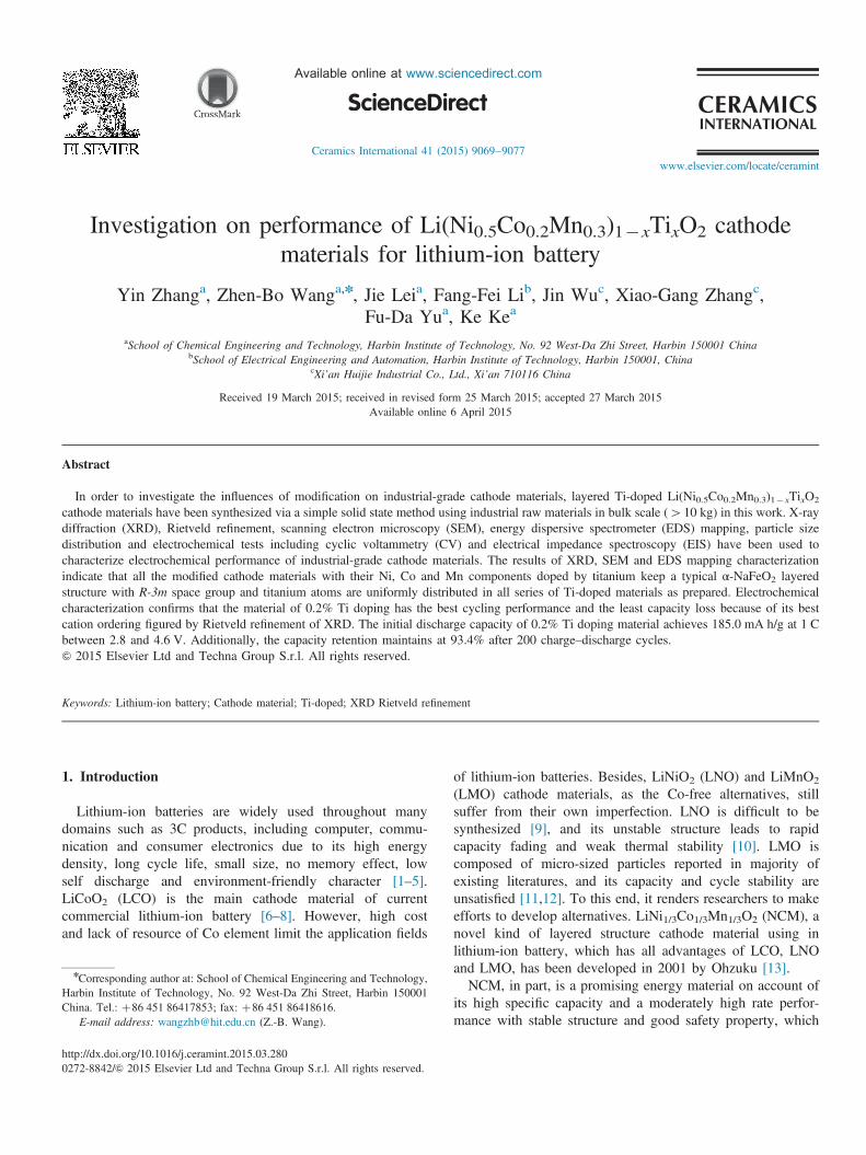
Fig. 1. XRD Rietveld refinement of NCM by different contents of Ti-doping: (a) NCM without Ti-doping, (b) Ti-0.2%, (c) Ti-0.4%, (d) Ti-0.8%, and (e) Ti-3.0%.
Y. Zhang et al. / Ceramics International 41 (2015) 9069–9077 9071
3. Results and discussion
Fig. 1 shows the XRD Rietveld refinement results of thematerials with different amounts of Ti-doping. LiNi0.5-Co0.2Mn0.3O2 electrodes without Ti doping are also preparedand examined carefully with XRD measurement in Fig. 1 forcomparison. It can be observed in Fig. 1 that all diffraction
peaks are clear and sharp, which means that the as-preparedsamples are well crystallized. It is well known that LiNi0.5-Co0.2Mn0.3O2 has a hexagonal crystal structure of α-NaFeO2
with a space group of R-3m [35–37] and the peaks of (006)/(10 2) and (108)/(110) at 2θ of about 38.31 and 64.91are allwell separated, respectively, demonstrating that typical layeredstructure of α-NaFeO2 with R-3m space group is well retained

Y. Zhang et al. / Ceramics International 41 (2015) 9069–90779072
by Ti-doping [38]. The results of XRD Rietveld refinement ofthe Ti-doping cathode materials are shown in Tables 1 and 2. Itcan be seen from Table 1 that the lattice constants, a and c,increase with the increase of doping contents because thediameter of Ti4þ (0.68 Å) is larger than that of Co3þ
(0.545 Å) and Mn4þ (0.53 Å) [39] and this rising tendencyof lattice constants may suggest that a portion of Ti4þ ions hasentered into the lattice. Besides, the integration of I(003)/I(104)41.2 means that the material has an excellent cation ordering[40]. Table 1 shows that the intensity ratios of I(003)/I(104) of allthe samples are greater than 1.2, which demonstrates that theas-prepared cathode materials have a good cation ordering. Aswould be expected, the values of c/3a rise with the increase ofTi doping content. This may come to a conclusion that all thesamples with Ti doping have a better cation ordering level thanthat of bare NCM, which indicates that Ti doping maydecrease the level of cation disorder in order to keep thestructure more stable [32] and it can also be seen from Table 2that there is only 0.0335 Ni (3a) in the site of Li (3a) (Li(3a)þNi (3a)¼1). Meanwhile sample Ti-3.0% has 0.0483 Ni(3a) in the site of Li (3a) though the intensity ratios of I(003)/I(104) of it is larger than that of sample Ti-0.2%. In addition, Ti-3.0% electrode has a weaker intensity of both I(003) and I(104),which suggests that the sample is not well crystallizedcompared with other Ti doped materials. Therefore, the sampleTi-0.2% has the minimum degree of cation disordering. Forthis reason, the diffusion resistance of Liþ could be reducedand the electrochemical properties of the material will performbetter due to the stable structure of material.
On account of 0.2% Ti-doped sample having the bestperformance, the scanning electron microscope (SEM) imagesof before and after 0.2% Ti-doped LiNi0.5Co0.2Mn0.3O2
Table 1Lattice constants of samples by different Ti-doping.
Sample a (Å) c (Å) c/3a I(003)/I(104)
Ti-0.0% 2.87193(4) 14.24301(8) 1.6531 1.4251Ti-0.2% 2.87262(0) 14.24603(7) 1.6531 1.4574Ti-0.4% 2.87256(1) 14.24728(6) 1.6533 1.4319Ti-0.8% 2.87290(2) 14.24897(9) 1.6533 1.4284Ti-3.0% 2.87506(1) 14.26152(4) 1.6535 1.5124
Table 2Rietveld refinements of samples by different Ti-doping.
Parameter Ti-0.0% Ti-0.2% Ti-0.4% Ti-0.8% Ti-3.0%
Li (3a) 0.9643 0.9665 0.9657 0.9642 0.9517Ni (3b) 0.5000 0.4999 0.4995 0.4995 0.4981Co (3b) 0.2000 0.1994 0.1990 0.1980 0.1929Mn (3b) 0.3000 0.2996 0.2991 0.2986 0.2947Ni (3a) 0.0357 0.0335 0.0343 0.0358 0.0483Ti (3b) 0.0000 0.0011 0.0024 0.0039 0.0143Rp% 3.49 3.33 3.55 3.47 3.27Rwp% 4.98 4.62 4.84 4.82 4.49χ2 3.488 3.045 3.339 3.324 2.887
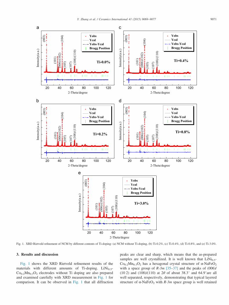
material are represented in Fig. 2. It can be seen that bothbare and modified powder particles keep spherical-like sec-ondary particles even undergoing the process of ball-millingand high-temperature calcination. In addition, the averageparticle sizes of all the samples are estimated to be 9–10 μm,which consist of nanoscale primary particles. However, it issurprising that the surface of Ti-doped material appears to be asimilar kind of film as shown in Fig. 2d, which may be acompound of lithium and titanium to our best knowledge thathas not been certified yet. Besides, there are no obviousdifferences between the bare material and 0.2% Ti-doped oneprobably because the content of Ti is only about 0.2%.Furthermore, in order to prove the modified cathode materialshomogeneously, EDS mapping of 0.2% Ti-doped material hasbeen given in Fig. 3. The result of mapping test reveals thepresence of nickel (pink), cobalt (yellow), manganese (blue),titanium (green), and oxygen (red), respectively, as shown inFig. 3 and it can be seen that not only transition metal elementsincluding nickel, cobalt and manganese are homogeneouslydistribution on the surface of the particles, but also titaniumatoms are uniformly distributed in 0.2% Ti-doped electrodematerial. Therefore, Ti has been doped on NCM cathodematerial successfully and homogeneously. Fig. 4 shows theparticle size distribution curve, and the details of it are revealedin Table 3. It can be seen in Fig. 4 and Table 3 that all thesamples of Ti-doped materials have smaller particle than thatof bare LiNi0.5Co0.2Mn0.3O2 material. Also, the parameters ofaverage particle diameter (D50) have a tendency of decreasingwith the increasing of Ti doping content, even though 0.4% Ti-doped material of D50 shows a bit abnormality. Fig. 4 alsoshows that the peak of larger particles shrinks at the end of themain peak, which indicates that the size of secondary particlescan probably be reduced by Ti doping so as to increase thedensity of materials. However, there is no significant influenceon the main peak of particle size distribution by Ti doping,illustrating that the secondary particles still keep the intrinsicgranularity after doping with Ti. Nonetheless, it can be seenfrom Fig. 4 and Table 3 that there is a small peak at 5.737 μm,which corresponds to D10 (particle size is smaller than5.737 μm accounted for 10%) parameter. Here, the most likelyreason is particle volume expansion caused by excessivecontent of Ti doping and it may affect the stability of material,leading to smaller particles falling off when the ball-millingmethod was used. In other words, the volume expansion maycause the looseness of particles structure and it will bedestroyed easily once it undergoes the ball-milling processand high-temperature calcination. In conclusion, these aboveresults may have the effects on the electrochemical propertiesof as-assembled half cell.In order to evaluate the electrochemical performance of Ti
modified cathode materials, half cells with Li/parent and theLiNi0.5Co0.2Mn0.3O2 doping by different contents of Ti areassembled and the results are shown in Figs. 5 and 6.Fig. 5 examines the initial charge and discharge behaviors of
a series of Ti-doped materials at room temperature. Chargetests were performed using a CC–CV charge, which meanscharging continued at 4.6 V in 1 C until the current reached a

Fig. 2. SEM of bare NCM (a, b) and NCM by 0.2% of Ti-doping (c, d). The scale bars in a and c are 20 μm, (b) and (d) are 1 μm.
Fig. 3. EDS maps of 0.2% Ti-doped materials.
Y. Zhang et al. / Ceramics International 41 (2015) 9069–9077 9073
value corresponding to 0.03 C, and then discharged to 2.8 Vcut-off potential in constant current 1 C. It can be seen inFig. 5 that the specific discharge capacity of pristine
LiNi0.5Co0.2Mn0.3O2 shows 183.5 mA h/g for the first cycle.At the same time, the initial specific discharge capacities of Ti-doped cathode materials reach 185.0 mA h/g, 183.3 mA h/g,
-20 -10 0 10 20 30 40 500
4
8
12
0.0% 0.2% 0.4% 0.8% 3.0%
Vol
ume(
%)
Particle Diameter (μm)
Fig. 4. Particle size distribution curve of NCM by different content ofTi-doping.
Table 3Particles size distribution of samples by different Ti-doping.
Samples D10/μm D50/μm D90/μm
Ti-0.0% 7.293 10.60 15.66Ti-0.2% 7.260 10.52 15.45Ti-0.4% 7.227 10.56 15.42Ti-0.8% 7.069 10.19 14.46Ti-3.0% 5.737 9.607 13.31
0 50 100 150 2002.5
3.0
3.5
4.0
4.5
0.0% 0.2% 0.4% 0.8% 3.0%
Pote
ntia
l(V)v
s. Li
/Li+
Specific capacity (mAh/g)
Fig. 5. The initial charge and discharge curves of 0.0%, 0.2%, 0.4%, 0.8%,3.0% Ti-doped LiNi0.5Co0.2Mn0.3O2 in the voltage range of 2.8–4.6 V.
0 40 80 120 160 2000
40
80
120
160
200
Spec
ific
capa
city
(mA
h/g)
Cycle Number
0.0% 0.2% 0.4% 0.8% 3.0%
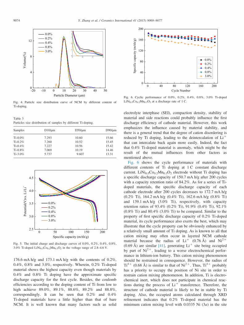
Fig. 6. Cyclic performance of 0.0%, 0.2%, 0.4%, 0.8%, 3.0% Ti-dopedLiNi0.5Co0.2Mn0.3O2 at a discharge rate of 1 C.
Y. Zhang et al. / Ceramics International 41 (2015) 9069–90779074
176.6 mA h/g and 173.1 mA h/g with the contents of 0.2%,0.4%, 0.8% and 3.0%, respectively. Wherein, 0.2% Ti-dopedmaterial shows the highest capacity even though materials by0.4% and 0.8% Ti doping have the approximate specificdischarge capacity for the first cycle. Besides, the coulombefficiencies according to the doping content of Ti from low tohigh achieve 89.0%, 89.1%, 88.6%, 89.2% and 88.8%,correspondingly. It can be seen that 0.2% and 0.4%Ti-doped materials have a little higher than that of bareNCM. It is well known that many factors such as solid
electrolyte interphase (SEI), compaction density, stability ofmaterial and side reactions could probably influence the firstdischarge efficiency of cathode material. However, this workemphasizes the influence caused by material stability, andthere is a general trend that the degree of cation disordering isreduced by Ti doping, leading to the deintercalation of Liþ
that can intercalate back again more easily. Indeed, the factthat 0.4% Ti-doped material is anomaly, which might be theresult of the mutual influences from other factors asmentioned above.Fig. 6 shows the cycle performance of materials with
different contents of Ti doping at 1 C constant dischargecurrent. LiNi0.5Co0.2Mn0.3O2 electrode without Ti doping hasa specific discharge capacity of 150.7 mA h/g after 200 cycleswith a capacity retention ratio of 84.2%. As for a series of Ti-doped materials, the specific discharge capacity of eachcathode electrode after 200 cycles decreases to 172.7 mA h/g(0.2% Ti), 164.2 mA h/g (0.4% Ti), 162.6 mA h/g (0.8% Ti)and 139.1 mA h/g (3.0% Ti), respectively, with capacityretention ratios of 93.4% (0.2% Ti), 91.9% (0.4% Ti), 92.1%(0.8% Ti) and 80.4% (3.0% Ti) to be compared. Similar to theproperty of first specific discharge capacity of 0.2% Ti-dopedmaterial, its cycle performance also exerts the best, which mayillustrate that the cycle property can be obviously enhanced bya relatively small amount of Ti doping. As is known to all thatcation mixing may often occur in layered NCM cathodematerial because the radius of Liþ (0.76 Å) and Ni2þ
(0.69 Å) are similar [41], generating Liþ site being occupiedby part of Ni2þ , leading to a worse electrochemical perfor-mance in lithium-ion battery. This cation mixing phenomenonshould be restrained in consequence. However, the radius ofTi4þ (0.68 Å) is similar to that of Ni2þ . Thus, Ti4þ probablyhas a priority to occupy the position of Ni site in order torestrain cation mixing phenomenon. In addition, Ti is electro-chemical inert, which does not participate in chemical reac-tions during the process of Liþ transference. Therefore, thestructure of cathode material is likely to be in stable by Tidoping. Also, the occupied atoms calculated through XRDrefinement indicates that 0.2% Ti-doped material has theminimum cation mixing level with 0.0335 Ni (3a) in the site

3.0 3.5 4.0 4.5
-1.0
-0.5
0.0
0.5
1.0
1.5 0.0% 0.2% 0.4% 0.8% 3.0%
Cur
rent
(A/g
)
Potential(V)vs. Li/Li+
Fig. 7. Cyclic voltammetry curves of 0.0%, 0.2%, 0.4%, 0.8%, 3.0% Ti-dopedLiNi0.5Co0.2Mn0.3O2 after 200 cycles at a discharge rate of 1 C.
Table 4Oxido-reduction potential of samples by different Ti-doping.
Samples Eoxidation (V) Ereduction (V) ΔE (V)
Ti-0.0% 4.017 3.510 0.507Ti-0.2% 4.013 3.521 0.492Ti-0.4% 4.014 3.523 0.491Ti-0.8% 4.102 3.436 0.666Ti-3.0% 4.096 3.466 0.630
0 50 100 150 2000
50
100
150
200
825.2Hz175.8Hz
825.2Hz175.8Hz
0.0% 0.2% 0.4% 0.8% 3.0%
-Z"(
ohm
)
Z'(ohm)
561.5Hz
Fig. 8. Nyquist plots of cells by 0.0%, 0.2%, 0.4%, 0.8%, 3.0% Ti-dopedLiNi0.5Co0.2Mn0.3O2 after 200 cycles at a discharge rate of 1 C.
Y. Zhang et al. / Ceramics International 41 (2015) 9069–9077 9075
of Li (3a). As a result, the more stable structure of the materialby Ti doping has a better cycle performance as shown inFig. 6.
The redox potential of the transition metal ions of NCMwith and without Ti doping during cycling can be evaluated bythe test of cyclic voltammetry (CV) [42]. Fig. 7 shows the CVcurves of Ti-doping materials with different contents between2.8 and 4.6 V after 200 cycles at 0.2 mV/s, in which metalliclithium is used as the counter and reference electrodes. It isknown that the oxidation states of Ni and Co, which areelectrochemically active among the three transition metalelements are 2þ and 3þ , respectively [43], while Mn withoxidation state 4þ is not active [35]. The relative broad peakbetween 3.7 and 4.2 V on the charge curve as shown in Fig. 7is ascribed to the oxidation of Ni ions (Ni2þ-Ni4þ ) and Coions (Co3þ-Co4þ ), accounting for the Liþ extraction fromthe NCM component [44]. The reduction peak around 3.5 Vwas observed on the discharge curve, illustrating the reductionof Ni ions (Ni4þ-Ni2þ ) and Co ions (Co4þ-Co3þ ), whichmeans that Liþ inserts back into the NCM layered material.The cathodic and anodic peaks of different contents of Ti-doped materials are used to demonstrate the potential differ-ence ΔE (Eoxidation–Ereduction) between Liþ extraction andinsertion, respectively, which can explain the cycle reversi-bility of as-prepared electrode [38]. In other words, the lessvalue of ΔE indicates that the cathode material has a bettercycle performance and the details of oxido-reduction potentialof samples with different Ti doping are revealed in Table 4. It
can be seen from Table 4 that ΔE of redox peaks of 0.2% and0.4% Ti-doped materials are approximately equal, which isless than 0.5 V after 200 cycles. However, 0.2% Ti-dopedsample have the bigger peak area than that of 0.4% Ti-dopedsample, even though the value of ΔE is a little bit lower, whichmeans the capacity retention ratio of 0.2% Ti-doped sample isbigger. Inversely, relatively more doping content materialshave a worse cycle reversibility because ΔE is bigger than thatof less doping content materials. Therefore, 0.2% Ti-dopedcathode material has the best cycle reversibility, owing to thestructure stability by Ti doping as shown in XRD refinements.Also, the results of CV measurement are consistent with thecycle performance as shown in Fig. 6.In order to illustrate the electrochemical effects by different Ti
doping contents, electrochemical impedance spectroscopy (EIS)technique is used to understand more about the surface circum-stance between cathode material and electrolyte by analyzing theNyquist plots [45]. Fig. 8 shows the AC impedance curves ofdifferent contents Ti-doped materials after 200 cycles at dischargerate of 1 C. The Nyquist plots include a semicircle at highfrequency, which represents charge transfer resistance (Rct) and thecapacitance between electrode and electrolyte interface, and a linewith a slope of about 451 at low frequency, which is assigned tothe lithium-ion diffusion in bulk materials [46–48]. It can be seenfrom Fig. 8 that the less contents of Ti, such as 0.2%, 0.4%, and0.8% Ti-doping samples, have smaller semicircles than that ofbare material and 3.0% Ti-doped material after 200 cycles,suggesting that the materials doping with relatively less contentshave positive electrochemical effects. Furthermore, Rct of everyTi-doped sample is less than that of bare NCM sample. The valuesof Rct are 151.7 Ω for bare NCM, 89.2 Ω for 0.2% Ti-dopedsample, 111.6Ω for 0.4% Ti-doped sample, 109.0 Ω for 0.8% Ti-doped sample and 150.8Ω for 3.0% Ti-doped sample, respec-tively. The reason is probably because the secondary particles arereduced by Ti doping, and increase the specific surface area of thematerials, thereby, the path of lithium-ion diffusion could beshortened. Besides, the results of EIS measurement are consistentwith the CV and cycle performance as shown in Figs. 6 and 7. Asa result, 0.2% Ti-doped material has the minimum value of charge

Y. Zhang et al. / Ceramics International 41 (2015) 9069–90779076
transfer resistance, leading to the best performance of electro-chemical among all samples with Ti doping.
4. Conclusions
The typical α-NaFeO2 layered Ti-doped Li(Ni0.5Co0.2-Mn0.3)1�xTixO2 cathode materials were synthesized via asimple solid state method using industrial raw materials inbulk scale (410 kg). All samples have a pure phasehexagonal α-NaFeO2 layered structure with R-3m spacegroup and there is no obvious impurity phase peaks observed.Ti was proved as being doped on NCM cathode materialssuccessfully and homogeneously. The electrochemical per-formance of cathode material is increased by Ti-doping, andthe material with 0.2% Ti doping has the best cyclingperformance and the least capacity loss due to the best cationordering. The initial discharge capacity is 185.0 mA h/g at1 C and the capacity retention is 93.4% after 200 charge–discharge cycles. All these results demonstrate that a smallamount of Ti doping could be beneficial to the improvementof electrochemical performance of cathode material to someextent, so as to offer some technical reliance and guidance forindustrialization.
Acknowledgment
This work acknowledges the National Natural ScienceFoundation of China (Grant no. 21273058), China Postdoc-toral Science Foundation (Grant nos. 2012M520731 and2014T70350), Heilongjiang Postdoctoral Financial Assistance(LBH-Z12089) for their financial support.
References
[1] J. Hassoun, K.S. Lee, Y.K. Sun, B. Scrosati, An advanced lithium ionbattery based on high performance electrode materials, J. Am. Chem.Soc. 133 (2011) 3139–3143.
[2] M. Armand, J.M. Tarascon, Building better batteries, Nature 451 (2008)652–657.
[3] Y. Xue, Z.B. Wang, F.D. Yu, Y. Zhang, G.P. Yin, Ethanol-assistedhydrothermal synthesis of LiNi0.5Mn1.5O4 with excellent long-termcyclability at high rate for lithium-ion batteries, J. Mater. Chem. A 2(2014) 4185–4191.
[4] J.B. Goodenough, K-Sung Park, The Li-ion rechargeable battery: aperspective, J. Am. Chem. Soc. 135 (2013) 1167–1176.
[5] J.B. Goodenough, Y. Kim, Challenges for rechargeable Li batteries,Chem. Mater. 22 (2010) 587–603.
[6] T. Nagaura, Prog. Batter. Battery Mater. 10 (1991) 218.[7] K. Mizushima, P.C. Jones, P.J. Wiseman, J.B. Goodenough, LixCoO2
(0oxo1): a new cathode material for batteries of high energy density,Mater. Res. Bull. 15 (1980) 783–789.
[8] G.M. Koenig, I. Belharouak, H. Deng, Y.K. Sun, K. Amine,Composition-tailored synthesis of gradient transition metal precursorparticles for lithium-ion battery cathode materials, Chem. Mater. 23(2011) 1954–1963.
[9] C.J. Kim, I.S. Ahn, K.K. Cho, S.G. Lee, J.K. Chung, Characteristics ofLiNiO2 thin films synthesized by Li diffusion on the surface oxidizedepitaxial layer of Ni-alloy, J. Alloy. Compd. 449 (2008) 335–338.
[10] C.S. Hua, K. Du, C.P. Tan, Z.D. Peng, Y.B. Cao, G.R. Hu, Study of fullconcentration-gradient Li(Ni0.8Co0.1Mn0.1)O2 cathode material forlithium ion batteries, J. Alloy. Compd. 614 (2014) 264–270.
[11] G.X. Fan, Y.W. Zeng, R.S. Chen, G.L. Lu, Microstructure and electro-chemical characterization of spherical-like orthorhombic LiMnO2 via co-precipitation, J. Alloy. Compd. 461 (2008) 267–272.
[12] T.J. Kim, D.Y. Son, J. Cho, B. Park, Enhancement of the electrochemicalproperties of o-LiMnO2 cathodes at elevated temperature by lithium andfluorine additions, J. Power Sources 154 (2006) 268–272.
[13] T. Ohzuku, Y. Makimura, Layered lithium insertion material of LiCo1/3Ni1/3Mn1/3O2 for lithium-ion batteries, Chem. Lett. 30 (2011) 642–643.
[14] K.C. Kam, M.M. Doeff, Aliovalent titanium substitution in layered mixedLi Ni–Mn–Co oxides for lithium battery applications, J. Mater. Chem. 21(2011) 9991–9993.
[15] Y. Cho, P. Oh, J. Cho, A new type of protective surface layer for high-capacity Ni-based cathode materials: nanoscaled surface pillaring layer,Nano Lett. 13 (2013) 1145–1152.
[16] S.K. Jung, H. Gwon, J. Hong, K.Y. Park, D.H. Seo, H. Kim, J. Hyun,W. Yang, K. Kang, Understanding the degradation mechanisms ofLiNi0.5Co0.2Mn0.3O2 cathode material in lithium ion batteries, Adv.Energy Mater. 4 (2014) 1–7.
[17] M. Noh, J. Cho, Optimized synthetic conditions of LiNi0.5Co0.2Mn0.3O2
cathode materials for high rate lithium batteries via Co-precipitationmethod, J. Electrochem. Soc. 160 (2013) A105–A111.
[18] Y.P. Chen, Y. Zhang, B.J. Chen, Z.Y. Wang, C. Lu, An approach toapplication for LiNi0.6Co0.2Mn0.2O2 cathode material at high cutoffvoltage by TiO2 coating, J. Power Sources 256 (2014) 20–27.
[19] J.M. Zhang, Z.R. Zhang, X.B. Wu, Z.X. Dong, Y. Yang, The effects ofAlF3 coating on the performance of Li[Li0.2Mn0.54Ni0.13Co0.13]O2
positive electrode material for lithium-ion battery, J. Electrochem. Soc.155 (2008) A775–A782.
[20] J.W. Kim, J.J. Travis, E. Hu, K.W. Nam, S.C. Kim, C.S. Kang, J.H. Woo,X.Q. Yang, S.M. George, K.H. Oh, S.J. Cho, S.H. Lee, Unexpected highpower performance of atomic layer deposition coated Li[Ni1/3Mn1/3Co1/3]O2 cathodes, J. Power Sources 254 (2014) 190–197.
[21] Y. Huang, F.M. Jin, F.J. Chen, L. Chen, Improved cycle stability andhigh-rate capability of Li3VO4-coated Li[Ni0.5Co0.2Mn0.3]O2 cathodematerial under different voltages, J. Power Sources 256 (2014) 1–7.
[22] Z.H. Han, J.P. Yu, H. Zhan, X.J. Liu, Y.H. Zhou, Sb2O3-modified LiNi1/3Co1/3Mn1/3O2 material with enhanced thermal safety and electrochemi-cal property, J. Power Sources 254 (2014) 106–111.
[23] T.E. Conry, A. Mehta, J. Cabana, M.M. Doeff, Structural underpinningsof the enhanced cycling stability upon Al-substitution in LiNi0.45Mn0.45-Co0.1�yAlyO2 positive electrode materials for Li-ion batteries, Chem.Mater. 24 (2012) 3307–3317.
[24] H.J. Bang, B.C. Park, J. Prakash, Y.K. Sun, Synthesis and electroche-mical properties of Li[Ni0.45Co0.1Mn0.45�xZrx]O2 (x¼0,0.02) via co-precipitation method, J. Power Sources 174 (2007) 565–568.
[25] G.H. Kim, S.T. Myung, H.S. Kim, Y.K. Sun, Synthesis of spherical Li[Ni(1/3�z)Co(1/3�z)Mn(1/3�z)Mgz]O2 as positive electrode material forlithium-ion battery, Electrchem. Acta 51 (2006) 2447–2453.
[26] Y.R. Gao, J. Ma, X.F. Wang, X. Lu, Y. Bai, Z.X. Wang, L.Q. Chen,Improved electron/Li-ion transport and oxygen stability of Mo-dopedLi2MnO3, J. Mater. Chem. A 2 (2014) 4811–4818.
[27] G.H. Kim, M.H. Kim, S.T. Myung, Y.K. Sun, Effect of fluorine on Li[Ni1/3Co1/3Mn1/3]O2�zFz as lithium intercalation material, J. PowerSources 146 (2005) 602–605.
[28] G.W. Yoo, B.C. Jang, J.T. Son, Novel design of core shell structure byNCA modification on NCM cathode material to enhance capacity and cyclelife for lithium secondary battery, Ceram. Int. 41 (2015) 1913–1916.
[29] J.P. Yu, Z.H. Han, X.H. Hu, H. Zhan, Y.H. Zhou, X.J. Liu, Theinvestigation of Ti-modified LiCoO2 materials for lithium ion battery,J. Power Sources 262 (2014) 136–139.
[30] S.T. Myung, S. Komaba, K. Hosoya, N. Hirosaki, Y. Miura, N. Kumagai,Synthesis of LiNi0.5Mn0.5�xTixO2 by an emulsion drying method andeffect of Ti on structure and electrochemical properties, Chem. Mater. 17(2005) 2427–2435.
[31] S.H. Kang, J. Kim, M.E. Stoll, D. Abraham, Y.K. Sun, K. Amine,Layered Li(Ni0.5�xMn0.5�xM2x0)O2 (M0 ¼Co, Al, Ti; x¼0, 0.025)cathode materials for Li-ion rechargeable batteries, J. Power Sources112 (2002) 41–48.

Y. Zhang et al. / Ceramics International 41 (2015) 9069–9077 9077
[32] K.C. Kam, A. Mehta, J.T. Heron, M.M. Doeff, Electrochemical andphysical properties of Ti-substituted layered nickel manganese cobaltoxide (NMC) cathode materials, J. Electrochem. Soc. 159 (2012)A1383–A1392.
[33] F.D. Yu, Z.B. Wang, F. Chen, J. Wu, X.G. Zhang, D.M. Gu, Crystalstructure and multicomponent effects in Li1þxMn2�x�yAlyO4 cathodematerials for Li-ion batteries, J. Power Sources 262 (2014) 104–111.
[34] A.C. Larson, R.B. Von Dreele, Gen. Struct. Anal. Syst. (GSAS) LAUR(2004).
[35] S.N. Nikkan, N. Munichandraiah, Synthesis and characterization ofcarbon-coated LiNi1/3Co1/3Mn1/3O2 in a single step by an inversemicroemulsion route, ACS Appl. Mater. Interfaces 1 (2009) 1241–1249.
[36] M.S. Goldsztaub, Bull. Soc. Francaise Mineral. 58 (1935) 6.[37] Y. Takeda, K. Nakahara, M. Nishijima, N. Imanishi, O. Yamamoto,
Sodium deintercalation from sodium iron oxide, Mater. Res. Bull. 29(1994) 659–666.
[38] J.T. Xu, S.L. Chou, Q.F. Gu, H.K. Liu, S.X. Dou, The effect of differentbinders on electrochemical properties of LiNi1/3Mn1/3Co1/3O2 cathodematerial in lithium ion batteries, J. Power Sources 225 (2013) 172–178.
[39] W. Luo, X. Li, J.R. Dahn, Synthesis, characterization, and thermalstability of Li[Ni1/3Mn1/3Co1/3�z(MnMg)z/2]O2, Chem. Mater. 22 (2010)5065–5073.
[40] J.H. Ju, K.S. Ryu, Synthesis and electrochemical performance of Li(Ni0.8Co0.15Al0.05)0.8(Ni0.5Mn0.5)0.2O2 with core-shell structure as cath-ode material for Li-ion batteries, J. Alloy. Compd. 509 (2011)7985–7992.
[41] Q. Liu, K. Du, H.W. Guo, Z.D. Peng, Y.B. Cao, G.R. Hu, Structural andelectrochemical properties of Co–Mn–Mg multi-doped nickel basedcathode materials LiNi0.9Co0.1�x[Mn1/2Mg1/2]xO2 for secondary lithiumion batteries, Electrchem. Acta 90 (2013) 350–357.
[42] T.L. Zhao, S. Chen, L. Li, X.F. Zhang, R.J. Chen, I. Belharouak, F. Wu,K. Amine, Synthesis, characterization, and electrochemistry of cathodematerial Li[Li0.2Co0.13Ni0.13Mn0.54]O2 using organic chelating agents forlithium-ion batteries, J. Power Sources 228 (2013) 206–213.
[43] Y. Koyama, I. Tanaka, H. Adachi, Y. Makimura, T. Ohzuku, Crystal andelectronic structures of superstructural Li1�x[Co1/3Ni1/3Mn1/3]O2
(0rxr1), J. Power Sources 119 (2003) 644–648.[44] W.H. Ryu, S.J. Lim, W.K. Kim, H.S. Kwon, 3-D dumbbell-like LiNi1/
3Mn1/3Co1/3O2 cathode materials assembled with nano-building blocksfor lithium-ion batteries, J. Power Sources 257 (2014) 186–191.
[45] L. Wang, J.S. Zhao, X.M. He, J. Gao, J.J. Li, C.R. Wan, C.Y. Jiang,Electrochemical impedance spectroscopy (EIS) study of LiNi1/3Co1/3Mn1/3O2 for Li-ion batteries, Int. J. Electrochem. Sci. 7 (2012) 345–353.
[46] M. Chen, C.Y. Du, B. Song, K. Xiong, G.P. Yin, P.J. Zu, X.Q. Cheng,High-performance LiFePO4 cathode material from FePO4 microsphereswith carbon nanotube networks embedded for lithium ion batteries,J. Power Sources 223 (2013) 100–106.
[47] J. Ni, Y. Han, L. Gao, L. Lu, One-pot synthesis of CNT-wiredLiCo0.5Mn0.5PO4 nanocomposites, Electrochem. Commun. 31 (2013) 84–87.
[48] G. Chen, Z.Y. Wang, D.G. Xia, One-pot synthesis of carbon nanotu-be@SnO2–Au coaxial nanocable for lithium-ion batteries with high ratecapability, Chem. Mater. 20 (2008) 6951–6956.