investigations on thermal behavior for different …heat conduction of ball screw framework &...
TRANSCRIPT

International Research Journal of Engineering and Technology (IRJET) e-ISSN: 2395 -0056
Volume: 03 Issue: 05 | May-2016 www.irjet.net p-ISSN: 2395-0072
© 2016, IRJET | Impact Factor value: 4.45 | ISO 9001:2008 Certified Journal | Page 1848
INVESTIGATIONS ON THERMAL BEHAVIOR FOR DIFFERENT COOLING
MEDIA IN A THROUGH HOLE BALL SCREW SHAFT USING
COMPUTATIONAL FLUID DYNAMICS TOOL
Mallikarjun S Padashetti1,Dr Sunil.S.Honnungar2,Sunil Lamani3,Naveen G Patil4
1,3Department of Mechanical Engineering St Martin’s Engineering college Secundrabad-500014,Telangana India 2Department of Mechanical Engineering SDM College of Engineering and Technology Dharwad 580002,Karnataka
India 4 Department of Mechanical Engineering MRCE Secundrabad-500014,Telangan India
---------------------------------------------------------------------***---------------------------------------------------------------------Abstract— The interest for higher efficiency and tight part resistances obliges machine instruments to have quicker and more exact feed drive frameworks. As attempted and tried innovation, ball screw drive frameworks are utilized a dominant part of machine apparatuses because of their minimal effort and high level of solidness. A fast ball screw drive framework creates more heat and results in more prominent thermal error. This thermal error leads to dimensional error of machined work-piece. The thermal error in system influences the positioning error of ball screw drive system. In this study, we examine the situation of a fluid cooling framework utilizing air and Ideal CO2 gas, as coolants in a Ball screw shaft to minimize the positioning error and warm dispersion of the ball frame work here we are varying inlet speed of the coolant. And the variation of temperature across nut and bearing were analyzed by varying inlet velocity of coolants. The accompanying study likewise shows level of situating positioning error improvement when a dissemination of different coolants passed, and by changing the speed of coolant.
Index Terms— BSA, Positioning accuracy, CFD,
1.INTRODUCTION The Ball screw drive frameworks are broadly utilized as a part of a few machine devices because of their less cost and high level of firmness. In the 1900s specialists found that around 40-70% of blunder was perceived in accuracy parts emerged due to heat generation [6]. In a machine device there are numerous heat sources, for example, pressure driven oil, drives, pumps, engine, guide ways, cutting activity and in orientation. A large portion of the exploration was done machine instrument warm conduct and warm slip pay on axles, orientation, machining process, and ball screw blunder remuneration. However couple of research has been focused on control of heat generation on ball screw system. Which unfavorably influence situating precision of machine instruments In past writing Xu et al. completed a novel heat
source control system called as "focus gap air cooling" on the Ball screw frameworks.
In this study coolants like air, Ideal CO2 gas, are passed into centre-hole Ball screw system to achieve a cooling effect. To decrease the thermal poisoning error the coolants passed at the Inlet with increasing velocity in order to predict the thermal behavior screw shaft screw system
Ball Screw Systems (BSA's) are essential parts in present day CNC machine devices that change over rotary movement into direct movement. They include a Ball Screw, with an outside helical furrow or raceway, a Ball Nut, with an inner helical depression or raceway, and a framework for re-coursing balls, which are moving components fitted between the Ball Screw and the Ball Nut. Below figure shows the vertical machining center.
1.1 Literature Review
Z.Z Xu,X.J.Liu: In ball screw warm bearing heat impact will results position slip; a rapid ball screw framework at high velocity for the most part makes more heat and results in more prominent heat development..It will come about the exactness of situating error. Here he used air as cooling media in a ball screw shaft to overcome thermal blunder of the ball screw framework and viability of air cooling framework, heat conduct models utilizing FEM and changed lumped capacitance strategy, were produced independently. Here they were recreated the temperature dispersion, and heat conduction of ball screw framework & air cooling execution were examined additionally to predict temperature appropriation with time.
Zhe-Zhu Xu,Xiao-Jing Liu and Sun-Ki Lyu: Here thermal error controls instead of thermal error minimization was studied Also screw and nut model was used for the study The screw was provided with central hole for passing air and axial thermal deformation was studied with no cooling, nut cooling, screw cooling, screw& nut cooling. Positioning error

International Research Journal of Engineering and Technology (IRJET) e-ISSN: 2395 -0056
Volume: 03 Issue: 05 | May-2016 www.irjet.net p-ISSN: 2395-0072
© 2016, IRJET | Impact Factor value: 4.45 | ISO 9001:2008 Certified Journal | Page 1849
was estimated with different condition of cooling i.e. nut cooling, screw cooling, screw& nut cooling. Analysis of positioning error was estimated at small stroke and big stroke condition from the study It is found that the thermal positioning error was maximum at no cooling condition Thermal images in no cooling, nut cooling, screw cooling, screw& nut cooling was shown. Also Noise was studied at different cooling conditions. Arun k sukumarn,Raji R.V: The effect of variation of rotating Reynolds no and axial Reynolds number on heat transfer & fluid flow in rotating annulus for a radius ratio, He has validated experimental work with the fluent results. He given Boundary condition as the wall of the inner rotating cylinder is kept at operating temperature. Results for various axial Reynolds number and radial Reynolds number were studied. Here he was presented how the axial Reynolds number and radial Reynolds number will change with respect to the change in heat transfer. From the analysis it was concluded that when rotational Reynolds number increases the magnitude of axial velocity decreases, rotation has significant only at low axial Reynolds number at high axial Reynolds the effect of rotation will very small.
C.H. Chien and J.Y. Jang : They have numerically analyzed
the 3D fluid motion & temperature distribution in a motorized high speed spindle with a helical water cooling channel. They used the k-epsilon turbulence model to develop the fluid model. The effect of different heat sources and cooling water flow rate were examined in detail. It was shown that the average maximum temperature along the spindle axis is decreased from 24.5°C to 22.2°C when the water flow rate was increased from 0.4 to 1.2L/min
1.2 Problem Description
If the temperature of screw shaft increases during operation, the screw shaft deforms due to heat thereby to lower the poisoning accuracy. If the temperature of screw shaft increases by 1°C, the screw shaft is elongated by 12µm/m.[7] so faster the speed of ball screw travel, more will be the heat generation and higher the temperature. And which will lowers the positioning accuracy of ball screw system. So if high accuracy is required it is necessary to take a temperature increase in screw shaft. So main objective of our study is to
1) To decrease the thermal deformation of screw shaft which will lowers the positioning error
2) Instead of conducting the experiment on real time basis it was opted to do simulation on the basis of experimental results available in literature. Further the possibilities of temperature and hence thermal error minimization were worked through the simulation software.
3) To decrease the temperature of screw shaft. 4) Modeling the hallow screw shaft and analyzing the
temperature and thermal deformation by passing
the different fluids like Air, Ideal CO2 gas by varying inlet velocity
2. Numerical analysis In the present work, numerical analysis of lead screw shaft is
done by passing different fluids like air and ideal CO2 gas
with increasing inlet velocity. The variation of temperature
and thermal deformation is analyzed across nut area and
Bearing area. The simulation is done in ANSYS CFX and the
results are validated using Experimental study mentioned in
Zhe-Zhu Xu,Xiao-Jing Liu,Chong-Hun Chol [2,3] was taken
and the dimensions and boundary conditions are same as
that in experimental setup.
2.1 Modeling
First step in CFD analysis is creation of geometry of flow
region for calculations. For our study we are modeling the
lead screw shaft with exact dimensions as shown below. For
exact representation of fluid flow the naming is done in
modeling itself .To represent the flow direction and flow
path inlet and outlet regions are named specifically
One important thing here is to creation of geometry for
CFD calculations is to allow flow sufficiently developed
across the entire length of domain. We need to encapsulate
the development of complex wake-making .In this study
diameter of flow of fluid is clearly defined and the type of
fluid also defined
2.2 Meshing
One of the most important step in analysis is to creation of mesh, CFD requires the subdivision of domain in to a number of domain geometry that is been created. for this particular study, hexahedron or Brick element with structural mesh is taken. The required fluid flows that are described in each of these cells are usually solved numerically so that the discrete values of parameter such as velocity, pressure and temperature are determined. This gives the CFD solution which is governed by number of cells within the domain. Generally the large numbers of cells are preferred to get exact results table.1 shows the mesh report.
Fig.1 Mesh model of screw shaft with Brick element.
International Research Journal of Engineering and Technology (IRJET) e-ISSN: 2395 -0056
Volume: 03 Issue: 05 | May-2016 www.irjet.net p-ISSN: 2395-0072
© 2016, IRJET | Impact Factor value: 4.45 | ISO 9001:2008 Certified Journal | Page 1850
2.3 Boundary conditions
The assumptions made for analysis is incompressible, two
dimensional axi-symmetric steady state flows.
Main heat generating units in this study is Ball screw shaft
and Bearings. The heat generation for 500rpm of screw shaft
is calculated for both nut area and Bearing area. The major
heat generation is friction between balls of the nut and
surface of screw shaft. The calculated heat flux on the surface
of nut area and Bearing area is directly applied in order to
predict the thermal error.
Fig.2 Screw shaft with boundary conditions
Table.2 Screw shaft with boundary conditions
Domain Zone Property Boundary condition
Fluid Inlet Flow regime Subsonic
Heat transfer Static temperature
Turbulence Medium& intensity and eddy viscosity
Mass& momentum Normal speed
Fluid Outlet Flow regime Subsonic
Mass and momentum
Average static pressure
Blend in Pressure profile
0.005
Average pressure Avg over whole outlet
Relative pressure 1.00 atm Solid Nut area Heat flux 400w/m^2
Bearing area Heat flux 350w/m^2
Convection area Convection 15.37w/m°C
3.0 Thermal analysis on screw shaft
3.1 For no cooling condition
In no cooling condition under the atmospheric temperature of 20°C there is a maximum of 48.37 °C is observed at mid section of the screw shaft. This temperature is analyzed at 500 stroke length of screw shaft at 500rpm of screw shaft. Under no cooling there is more positioning error causes on screw shaft due to the thermal deformation. The variation of temperature and corresponding deformation is shown in below
Fig.3 Temperature variation in screw shaft in no cooling
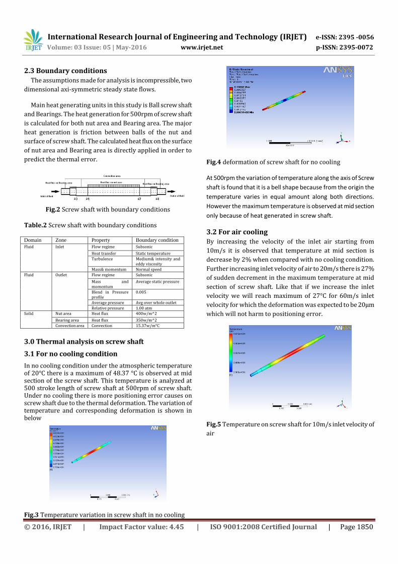
Fig.4 deformation of screw shaft for no cooling
At 500rpm the variation of temperature along the axis of Screw
shaft is found that it is a bell shape because from the origin the
temperature varies in equal amount along both directions.
However the maximum temperature is observed at mid section
only because of heat generated in screw shaft.
3.2 For air cooling
By increasing the velocity of the inlet air starting from
10m/s it is observed that temperature at mid section is
decrease by 2% when compared with no cooling condition.
Further increasing inlet velocity of air to 20m/s there is 27%
of sudden decrement in the maximum temperature at mid
section of screw shaft. Like that if we increase the inlet
velocity we will reach maximum of 27°C for 60m/s inlet
velocity for which the deformation was expected to be 20µm
which will not harm to positioning error.
Fig.5 Temperature on screw shaft for 10m/s inlet velocity of
air

International Research Journal of Engineering and Technology (IRJET) e-ISSN: 2395 -0056
Volume: 03 Issue: 05 | May-2016 www.irjet.net p-ISSN: 2395-0072
© 2016, IRJET | Impact Factor value: 4.45 | ISO 9001:2008 Certified Journal | Page 1851
Fig.6 Deformation of screw shaft for 20m/s inlet velocity of
air
Fig.7 Variation of Temperature across the diameter of screw
shaft at different sections for 10m/s inlet velocity of air
Fig.8 Variation of Temperature across the diameter of screw
shaft at different sections for 20m/s inlet velocity of air
Fig.9 Variation of deformation of screw shaft Vs inlet velocity of air
3.3 Ideal CO2 gas as a coolant
Under special conditions its cooling capacity lies between air and water. So nearly 75% of less velocity is required as compared to air to overcome from positioning error. Also it has good corrosive resistance. Fig 18 shows the temperature variation for Ideal CO2 gas cooling.
Fig.10 Temperature on screw shaft for 10m/s inlet velocity
of Ideal CO2 gas
Fig.11 Deformation on screw shaft for 10m/s inlet velocity
of Ideal CO2
Fig.12 Variation of Temperature across the diameter of
screw shaft at different sections for 10m/s Ideal CO2 gas
cooling

International Research Journal of Engineering and Technology (IRJET) e-ISSN: 2395 -0056
Volume: 03 Issue: 05 | May-2016 www.irjet.net p-ISSN: 2395-0072
© 2016, IRJET | Impact Factor value: 4.45 | ISO 9001:2008 Certified Journal | Page 1852
Fig.13 Variation of Temperature across the diameter of
screw shaft at different sections for 20m/s Ideal CO2 gas
cooling
The decrease in deformation on screw shaft increase in
velocity of inlet Ideal CO2 gas is shown below
Fig.14 Variation of deformation of screw shaft Vs inlet
velocity of Ideal CO2 gas
4.0 CONCLUSIONS
In this study simulation of screw shaft is carried to predict the thermal deformation, air, and Ideal CO2 gas are used to reduce the deformation. For air, thermal deformation is reduced up to 20µm for 60m/s inlet velocity. So to overcome this we have used Ideal CO2 gas which will act as coolant and also it is non corrosive. Almost 40% less velocity is required to achieve the thermal deformation within 20 µm. Deformation decreases 80% when Inlet velocity of air is increased from 0m/s to 60m/s. Deformation decreases 87% when Inlet velocity of Ideal CO2 gas is increased from 0m/s to 40m/s.
F
Fig.15 comparison of temperature for air and Ideal CO2
gas cooling
Fig. 16 Comparison of deformation air and Ideal CO2 gas
cooling
REFERENCES [1] H.K.Veersteeg and W.Malalasekera “An introduction to
computational fluid dynamics” Vol.1,pp.[17-19]
[2] Z. Xu , X.J.Liu , H.K.Kim , J.H.Shin, S.K.Lyu “Thermal error forecast and performance evaluation for an air-cooling ball screw system” pp[606-611]
[3] Zhe-Zhu Xu, Xiao-Jing Liu, Chong-Hun Choi, and Sung-Ki Lyu.“A Study on Improvement of Ball Screw System Positioning Error with Liquid-Cooling” [2-7]
[4] Harris, T. A., “Rolling bearing analysis,” Wiley Sons, New York 1991, pp.[540-560]
[5] Wei, J., Zhang, Q., Xu, Z. Z., and Lyu, S. K., “Study on precision grinding of screw rotors using CBN wheel,” Int. J. Precis. Eng. Manuf., Vol. 11, pp.[ 651-658].
[6] Bryan J International status of thermal error research (1990) CIRP Ann.–Manuf. Technol., 1990, 39(2), 645–656.
[7] NSK Ball screw tutorial pp [8-9]
[8] Holman, J. P., Heat and mass Transfer, McGraw-Hill Inc., New York, 1981.
[9] Chapra, S. P. and Ganale, R. P., Numerical Methods for Engineers, McGraw-Hill Inc.,New York, 1985.
[10] J. S. Chen, “A study of thermally induced machine tool errors in real cutting conditions,” Int. J. Mach. Tools Manuf., vol. 36, 1996, pp.[1401–1411].

International Research Journal of Engineering and Technology (IRJET) e-ISSN: 2395 -0056
Volume: 03 Issue: 05 | May-2016 www.irjet.net p-ISSN: 2395-0072
© 2016, IRJET | Impact Factor value: 4.45 | ISO 9001:2008 Certified Journal | Page 1853
[11] Raji R.V,Arun.K.Sukumaran “Fluid flow simulations within Rotating annulus” pp.[2-4]
[12] Halliday, David, Resnick, and Robert, Physics, Erlangga, Jakarta, 1996.
[13] Kleis I. and Kulu P.: Solid Particle Erosion. Springer-Verlag, London, 2008.
[14] T. A. Harris, Rolling Bearing Analysis, Wiley & Sons, New York, 1991, pp. 540–560.
[15] ANSYS, 14 User Guide, ANSYS Inc., Canonsburg, PA, USA, (Website: www.ansys.com) 2014