invitation to bid (sbd 1) - south african astronomical ... · invitation to bid (sbd 1) ......
TRANSCRIPT

Page 1 of 20
INVITATION TO BID (SBD 1)
YOU ARE HEREBY INVITED TO BID FOR THE FOLLOWING SPECIFIED SUPPLY REQUIREMENTS
BID NUMBER: NRF/SAAO/2014/003 CLOSING DATE: 13 June 2014 CLOSING
TIME 15:00
BID DESCRIPTION
SAAO Sutherland : EARTHING INFRASTRUCTURE
Bidders are required to fill in and sign the written offer form (SBD7 Contract Form – Part 1) at end of this Invitation.
Preferential Procurement System applicable (points for price : points for procurement preference): 80:20
Validity period from date of closure: 60 days
EITHER PHYSICALLY OR BY COURIER OR EMAIL (PDF FORMAT ONLY)
SAAO Site (next to The River Club) Observatory Road Observatory Cape Town
Emailed PDF file name format is “Bid Number / Supplier Name”
Bidders are required to deliver Bids to the correct address timeously. If the Bid is delivered late to the SAAO address, it will not be considered.
All Bids must be submitted on the official forms in this invitation (not to be re-typed) with additional information supplied on attached supporting schedules. Word version is available on request.
This Bid is subject to the Preferential Procurement Policy Framework Act and its 2011 Regulations, the General Conditions of Contract (NRF website) and Special Conditions of Contract as stipulated in this invitation.

Page 2 of 20
ANY ENQUIRIES REGARDING THE BIDDING PROCEDURE DIRECTED TO:
Contact Person: Grant Southey
Tel: 021 4609376
Email: [email protected] (do not use this address to submit proposals)
Contact Person:
Tel:
Email:
NAME OF BIDDER
REPRESENTED BY
POSTAL ADDRESS
PHYSICAL ADDRESS
TELEPHONE NUMBER CODE NUMBER
CELL PHONE NUMBER CODE NUMBER
FACSIMILE NUMBER CODE NUMBER
E-MAIL ADDRESS
VAT REGISTRATION NUMBER
COMPANY REGISTRATION NUMBER

Page 3 of 20
DESCRIBE PRINCIPAL BUSINESS ACTIVITIES:
TYPE OF COMPANY/FIRM [Tick applicable box]
Partnership/Joint Venture/Consortium One person business/sole proprietor
Close Corporation Company
(Pty) Limited Other
COMPANY CLASSIFICATION [Tick applicable box]
Manufacturer Supplier
Professional Service Provider Other service providers e.g. transporter, etc.
Has an original and valid tax clearance certificate been submitted? [Tick Applicable Box]
Yes
No
Has a Preference Claim form claiming your Preference Points (SBD6.1) been submitted (a B-BBEE status level verification certificate must support preference points claimed) [Tick Applicable Box]
Yes
No
If Yes, who was the B-BBEE certificate issued by [Tick Applicable Box]
An accounting officer as contemplated in the Close Corporation Act (CCA)
A verification agency accredited by the South African Accreditation System (SANAS)
A registered auditor
Are you the accredited representative in South Africa for the goods/services/works offered? If Yes, please enclose proof.
Yes
No
Is the Bid Pack split into “Technical” and “Awarding” sections? Yes
No
Are certified copies of Certificate of Incorporation (as per entity type) enclosed? Yes
No
Page 4 of 20
1. Background to the National Research Foundation and its Business Units
The National Research Foundation (“NRF”) is a juristic person established in terms of Section 2 of the
National Research Foundation Act, Act 23 of 1998 and a Schedule 3A Public Entity in terms of the Public
Finance Management Act. The NRF is the government’s national agency responsible for promoting and
supporting research and human capital development through funding, the provision of National Research
Facilities and science outreach platforms and programs to the broader community in all fields of science
and technology, including natural science, engineering, social science and humanities.
The South African Astronomical Observatory (SAAO) is the national centre for optical and infrared
astronomy in South Africa. It is a facility of the National Research Foundation under the Department of
Science and Technology. Its prime function is to conduct fundamental research in astronomy and
astrophysics by providing a world-class facility and by promoting astronomy and astrophysics in Southern
Africa. SAAO headquarters are in the suburb of Observatory in Cape Town. The main telescopes used for
research are located at the SAAO observing station (32°22.795’S 20°48,657’E) near Sutherland in the
Northern Cape, a 4-hour drive from Cape Town.
2. Scope/Summary of Supply
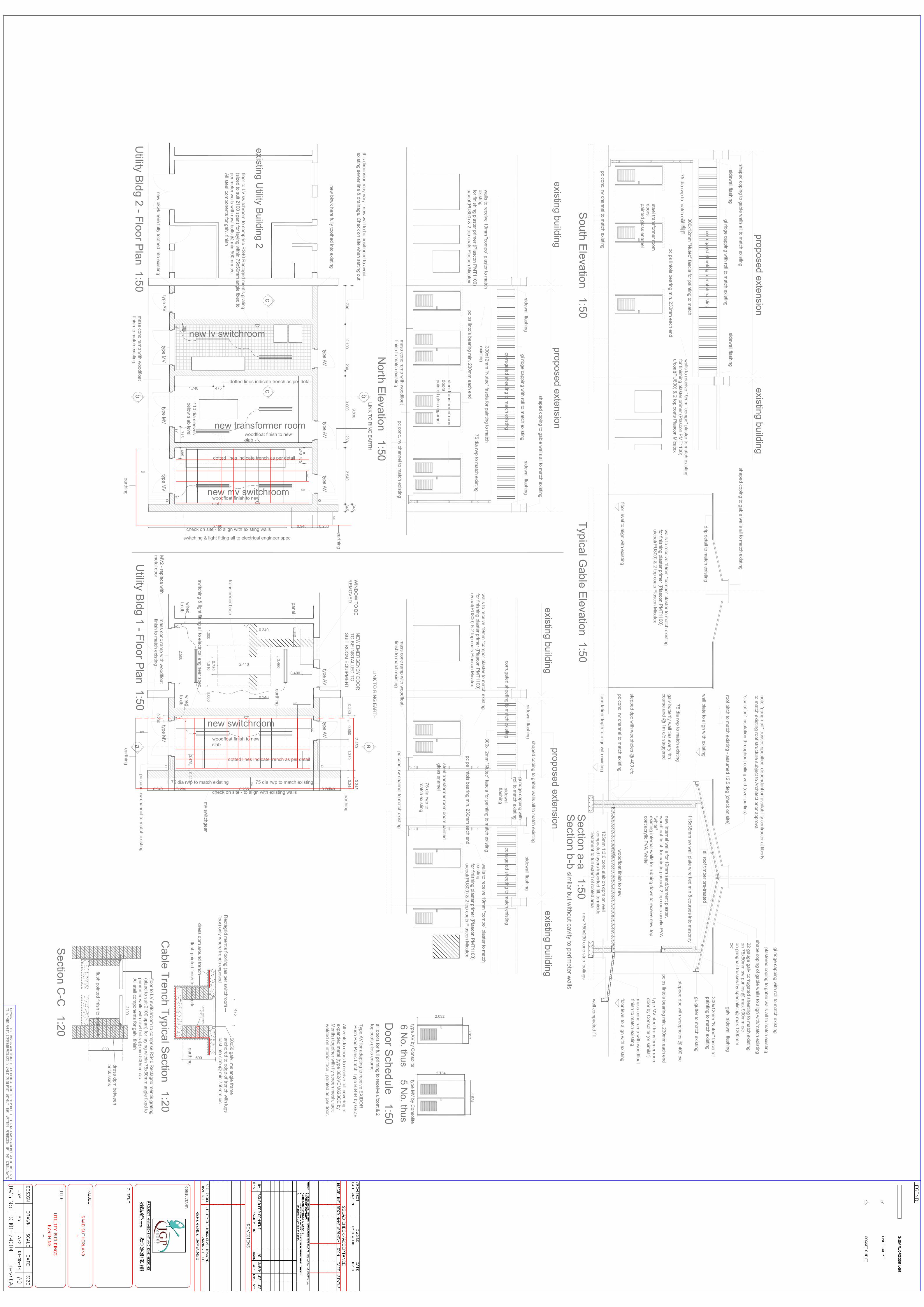
During the earthwork and preliminary civil construction activities associated with the UTILITY Building
Extensions it is deemed prudent to install the earthing infrastructure associated with an overall Earth
Bonding Protection System.
The scope of this particular project is to supply and install the earthing infrastructure to which the future
Protection equipment will interconnect.
Reference is to be made to the enclosed Data Sheets [Appendix 1] and Drawings [Appendix 2], all forming
an integral part of this documentation.
3. Context
3.1 Electrical Safety Earth System
• The Electrical Safety Earth System is primarily designed to minimise the risk of electrocution of personnel and forms an integral part of the bulk electrical supply to the Facility.
Target Solutions:
• Soil resistivity tests have been conducted on site and the associated designs of discrete earth mats form part of this project.
• The requirement is to achieve an overall earth resistance < 2 ohms. • Conductors forming the copper earth mat will be uninsulated and welded together prior to installation. • The conductors linking between the earth mat and the ‘Safety Earth’, Potential Equilisation Bar (PEB)
[Appendix 1: Item 12], must have an outer insulation, particularly 300mm below the soil / air interface.

Page 5 of 20
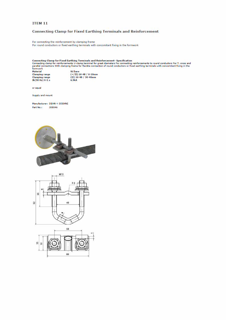
• To maintain continuity of the earth through the reinforced concrete floors, fixed Earth Terminals [Appendix 1: Item 4A and Item 11] are to be cast into the concrete with the disks being flush with the outer surface; allowing termination of an earth conductor.
• Earth bonding from the above mentioned PEB’s will be continued by the electrical installation contractor.
3.2 High Quality Earth System
• The High Quality Earth System is primarily designed to minimise the electrical interference induced into instrumentation and communication networks and forms an integral part of the process control infrastructure
Target Solutions:
• Install discrete earth conductors linking between the earth mat and the ‘High Quality Earth’, Potential Equilisation Bar (PEB) [Item 12] within the MCC Room; having an outer insulation, 300mm below of the soil / air interface.
• Earth bonding from the MCC Room, HQ - PEB will be continued by the electrical installation contractor.
3.3 General
• Each of the Earthing Systems must be specifically installed to suit the actual soil conditions and construction constraints.
3.4 Conduct earth resistance tests on site to determine the actual rating of earth infrastructure.
• Liaise with the Engineer to resolve actual methodologies. • Complete and sign a Certificate of Compliance for each earthing infrastructure;
4. Selection and Awarding of Contract
This Bid is evaluated through a two-stage process.
Stage 1 – Selection of Qualified Bidders 4.1.
The Bidders’ Bid response/submission is evaluated against the Bid invitation specifications.
Evaluation is made in accordance to evaluation criteria and the scoring set published in this document.
Stage 2 – Awarding of the Contract 4.2.
Bidders are compared on a fair and equal basis taking into account all aspects of the proposals.
The award criteria are:
Price - with the lowest priced Bid on an equal and fair comparison basis receiving the highest
price score as set out in the 2011 Preference Regulations.
Preference - preference points as claimed in the preference claim form are added to the price
ranking scores and the highest combined score is nominated for the contract award.
Administration - Contracts are awarded where Bidders have supplied the relevant administrative
documentation, especially the Tax Certificate.

Page 6 of 20
5. Specification
Supplies Required 5.1.
The earthing concept for the site is outlined as follows: ·∙ _Installation of a single earth mat ·∙ _Earth mat is to be installed under the floor to ensure safety of any person under fault conditions. ·∙ _Ring earth is to be installed around the building to ensure safety of any person standing next to the building. ·∙ _Ring earth is to have earth enhancing material installed with the cable at a rate of 20kg per 5m
Quality Requirements including applicable standards 5.2.
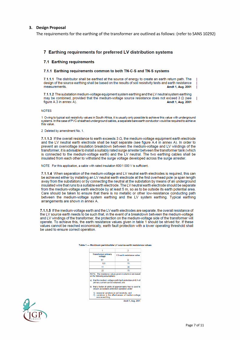
The following SANS codes of practice are applicable: o SANS 10199: The Design and installation of earth electrodes o SANS 10292: Earthing of LV distribution Systems o SANS 1063: Earth rods, couplers and connections o IEEE80: Guide for Safety in AC Substation Grounding
Health and Safety Requirements 5.3.
The successful bidder will be required to ensure the safety of all employees on site and supply all their staff
with the required personal protective clothing.
The successful bidder will also have to submit proof, to SAAO, of their registration and good standing with
the workman's compensation fund.
Local Content Requirements for Designated and Non-Designated Sectors 5.4.
No local content has been specified for the products/services supplied in this contract other than the
contracted suppliers being required to be based locally in South Africa.
Evidence of Supply Capacity and Capability (Technical Merit) 5.5.
Bidders are required to provide a profile of themselves for evaluation of their capacity to supply the required
equipment including resources including details of agency or distribution agreements that they hold as well
as details of equipment that they manufacture
Bidders are required to provide three (3) written references from previous clients in which the clients
declare their experience with the bidders. Letter supplied at the end of the document.
Page 7 of 20
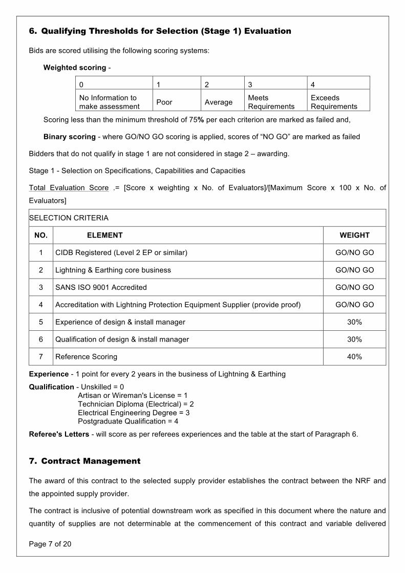
6. Qualifying Thresholds for Selection (Stage 1) Evaluation
Bids are scored utilising the following scoring systems:
Weighted scoring -
0 1 2 3 4
No Information to make assessment Poor Average Meets
Requirements Exceeds Requirements
Scoring less than the minimum threshold of 75% per each criterion are marked as failed and,
Binary scoring - where GO/NO GO scoring is applied, scores of “NO GO” are marked as failed
Bidders that do not qualify in stage 1 are not considered in stage 2 – awarding.
Stage 1 - Selection on Specifications, Capabilities and Capacities
Total Evaluation Score .= [Score x weighting x No. of Evaluators]/[Maximum Score x 100 x No. of
Evaluators]
SELECTION CRITERIA
NO. ELEMENT WEIGHT
1 CIDB Registered (Level 2 EP or similar) GO/NO GO
2 Lightning & Earthing core business GO/NO GO
3 SANS ISO 9001 Accredited GO/NO GO
4 Accreditation with Lightning Protection Equipment Supplier (provide proof) GO/NO GO
5 Experience of design & install manager 30%
6 Qualification of design & install manager 30%
7 Reference Scoring 40%
Experience - 1 point for every 2 years in the business of Lightning & Earthing
Qualification - Unskilled = 0 Artisan or Wireman's License = 1 Technician Diploma (Electrical) = 2 Electrical Engineering Degree = 3 Postgraduate Qualification = 4
Referee's Letters - will score as per referees experiences and the table at the start of Paragraph 6.
7. Contract Management
The award of this contract to the selected supply provider establishes the contract between the NRF and
the appointed supply provider.
The contract is inclusive of potential downstream work as specified in this document where the nature and
quantity of supplies are not determinable at the commencement of this contract and variable delivered

Page 8 of 20
quantity where the exact supplies are specified at the commencement of this contract except for quantities
and date of delivery.
Such potential downstream supplies follows the process of a detailed quotation of the supply required,
evaluation of the supply quotation received and, where necessary, request either further detail or negotiate
upon value of supply quoted and the issue of an official Purchase Order for the agreed supply prior to the
commencement of such supply.
Variable delivered supply follows the process of issuing a detailed official Purchase Order specifying the
exact description including catalogue numbers and unit pricing as in this contract as well as the quantity,
date of the required delivery and location of the delivery. Variable delivered supply generates a stream of
“call off” instructions as and when the NRF requires these the contracted supplies.
8. Contract Period
The contract will commence with immediate effect upon the signing of the Acceptance of Written Offer and
will continue until 30 June 2014.
9. Supply Performance Validation
The certificate and the related report of delivery/installation/progress milestone/commissioning will be
validated by a NRF representative prior to payment of final invoices.
10. Payment Intervals
The NRF undertakes to pay performance validated invoices in full within thirty (30) days from the monthly
statement date or upon agreed payment intervals as accepted in this contract.
No invoices for outstanding deliverables or for any unproductive or duplicated time spent by the service
provider will be validated for payment. The NRF does not accept predating of invoices.
11. Pricing Schedule for the Duration of the Contract
(Standard Bidding Document 3.1 and 3.3)
NOTE Only firm prices will be accepted. The price quoted is fully inclusive of all costs and taxes. No changes or extensions or additional ad hoc costs are accepted once the contract has been awarded.
Detailed information is optional and is provided as annexures to the details provided below.
Bid price in South African currency, foreign exchange risk is for the account of the Bidder.
Pricing is subject to the addition of Preference Points as stipulated in the section below - Standard Bidding Document 6.1 Preference claim form
OFFER TO BE VALID FOR 150 days FROM THE CLOSING DATE OF BID.


Earthing Design Proposal – Utilities Building No 1 - SAAO
Prepared By:
John Page (PrEng; Govt Cert)
11 November 2013
2 The Ridge Office Park, Door-de Kraal Avenue, Kenridge 7550
P O Box 2008, Durbanville 7550; Tel: 021-9146385 Fax: 021-9146328
E-mail: [email protected]. Reg. 87/007636/23. VAT 4410142303

Page 2 of 11
1. Introduction
2. Soil Prospection
3. Design Proposal
a. Single Earth Mat Design
4. Discussion and Conclusion

Page 3 of 11
1. Introduction
The following paragraphs deal with the proposed design of the earthing for the Utilities Building No1
at SAAO.
The design was conducted in terms of the following SANS codes of practice:
o SANS 10199: The Design and installation of earth electrodes
o SANS 10292: Earthing of LV distribution Systems
o SANS 1063: Earth rods, couplers and connections
o IEEE80: Guide for Safety in AC Substation Grounding

Page 4 of 11
2. Soil Prospection
Results from a soil prospection survey conducted on site are shown below. Please note that these
results are used for all further design requirements. Actual results from the site may be different to
these due to seasonal variations and soil movement due to construction.
CUSTOMER INFORMATION JGP Group Utilities Building No 1 SAAO
TEST AND EQUIPMENT INFORMATION S. S.
Test Date Weather Clear Soil Condition Dry
Wenner 4 Point Megger - Null balance 1044M9202700988 14/11/2012
Calibration Certificate 1006/65
BASIC SKETCH OF TEST LINES
TEST RESULTS
Calculated Resistivity ( Ω
)
SOIL PROSPECTION
Line 1 Megger Reading
(Ω
)
Line 2 Calcuated
Resistivity (Ω) Probe Spacing
(m)
2013/11/11
Client
Test Done By
Calibration Date
Project Name Location
Test Method Test Equipment Serial No of Equipment
1 2 3 4
Megger Reading ( Ω
)
37.70 87.96
6 7
3.88 83.69 3.33 73.14
4 125.66 5 *ressistivity calculated according to Ω
=2 Ω
aR where a = probe spacing and R = megger reading
TEST LINE

Page 5 of 11
From the data above
ρ1 50 Ωm
ρ2 100 Ωm
500
1000
2000
0.1
1.4
1.4
Lightning Protection
Universal Lightning Protection & Earthing services cc VAT No. 4790128088 CK 2000/028596/23
Services
16 Wright Street, Sidwell, 6061 PO Box 7085, Port Elizabeth, 6055 Tel. 041 451 3476 Fax. 041 453 5724
0
20
40
60
80
100
120
140
0 1 2 3 4 5 6
Ap
par
en
t R
esi
stiv
ity,
ρa
(Ωm
)
Probe Spacing (m)
TEST LINE 1
TEST LINE 2
0.001
0.01
0.1
1
10
100
1000
0.1 1 10 100 1000ρa/ρ1
a/h
Figure 1 Plot of Apparent Resistivity (ρa) vs Probe Spacing (a)
Figure 2 Sunde's Graphical Method
Interpolated plot of
apprent resistivity from Figure 1

Page 6 of 11
From the interpolated curve on Sunde's Grpahical Method (figure 2):
ρa/ρ1 1.5 Ωm
a/h 1.4
ρa 75 Ωm
From the data shown on the apprent resitivity (figure 1)
a 1.7 m
h 1.2 m
Summary of data for Two-Layer Soil Model
ρ1 50 Ωm
ρ2 100 Ωm
h 1.2 m
k 0.33 (reflection factor)
Graphical Representation of Model
NOTES:
In general these initial readings indicate performance of the earth, although later readings may be
somewhat different as they will be affected by consolidation of the soil and seasonal variations in moisture,
temperature and mineral content.
Services
16 Wright Street, Sidwell, 6061 PO Box 7085, Port Elizabeth, 6055 Tel. 041 451 3476 Fax. 041 453 5724
Lightning Protection
Universal Lightning Protection & Earthing services cc VAT No. 4790128088 CK 2000/028596/23
15
150
0.1 1 10
ρa
a
2 Layer Model
Avg of data
Page 7 of 11
3. Design Proposal
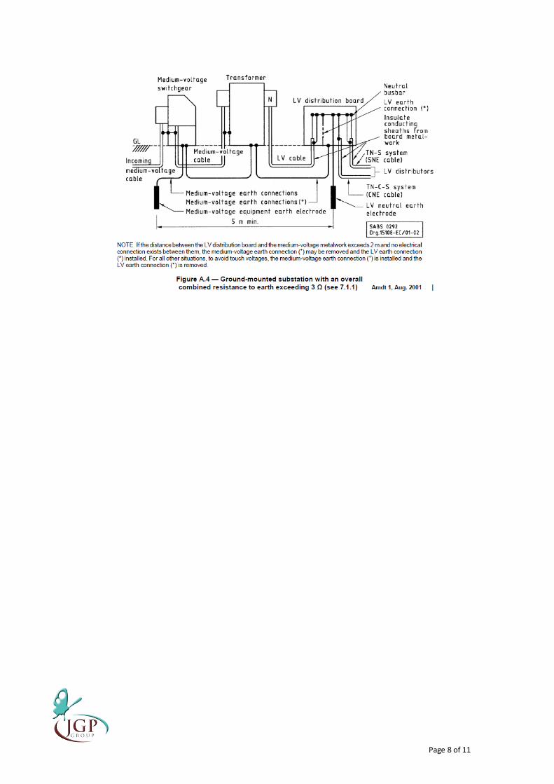
The requirements for the earthing of the transformer are outlined as follows: (refer to SANS 10292)
Page 8 of 11

Page 9 of 11
3a Single Earth Electrode Design
From the above requirements, should a single earth electrode be required the following design
would be applicable.
(*Calculations based on IEEE80-2000 Guide for Safety in AC Substation Grounding)
Customer JGP Group
Project SAAO Utilities Building No 1
Mat Description Custom
Mat Geometrical Features
Length 8 m
Width 2.5 m
Grid Spacing - Length 0.5 m
Grid Spacing - Width 0.5 m
Buried Depth 0.5 m
Diameter of cable 0.016 m
No of earth spikes 5
Diameter of earth spikes 0.016 m
Length of each earth spike 0.1 m
Area 20 m2
Soil Resistivity Values
ρ1 50 Ωm
ρ2 100 Ωm
h 1.2 m
k 0.33 (reflection factor)
Grpahical Representation of soil model
EARTH ELECTRODE RESISTANCE ESTIMATE
Lightning Protection
Universal Lightning Protection & Earthing services cc VAT No. 4790128088 CK 2000/028596/23
16 Wright Street, Sidwell, 6061 PO Box 7085, Port Elizabeth, 6055 Tel. 041 451 3476 Fax. 041 453 5724
Services
1
10
100
1000
0.1 1 10
Ap
par
en
t R
esi
stiv
ity,
ρa
Probe Spacing, a
Figure 1 Average Resistivity Data and 2-Layer Model Data
2 Layer Model
Avg of data
Page 10 of 11
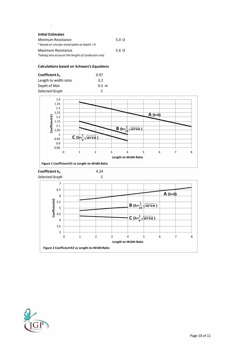
Initial Estimates
Minimum Resistance 5.0 Ω* based on circular metal plate at depth = 0
Maximum Resistance 5.6 Ω*taking into account the length of conductor only
Calculations based on Schwarz's Equations
Coefficient k1 0.97
Length to width ratio 3.2
Depth of Mat 0.5 m
Selected Graph C
Coefficient k2 4.24
Selected Graph C
Lightning Protection
Universal Lightning Protection & Earthing services cc VAT No. 4790128088 CK 2000/028596/23
Services
16 Wright Street, Sidwell, 6061 PO Box 7085, Port Elizabeth, 6055 Tel. 041 451 3476 Fax. 041 453 5724
0.85
0.9
0.95
1
1.05
1.1
1.15
1.2
1.25
1.3
1.35
1.4
0 1 2 3 4 5 6 7 8
Co
eff
icie
nt k
1
Length-to-Width Ratio
Figure 1 Coefficient K1 vs Length-to-Width Ratio
B (h=
)
C (h=
)
A (h=0)
3
3.5
4
4.5
5
5.5
6
6.5
7
0 1 2 3 4 5 6 7 8
Co
eff
icie
nt k
2
Length-to-Width Ratio
Figure 2 Coefficient K2 vs Length-to-Width Ratio
A (h=0)
B (h=
)
C (h=
)

Page 11 of 11
4. Recommendations & Conclusion
The earthing system must be designed in accordance with
o SANS 10199: The Design and installation of earth electrodes
o SANS 10292: Earthing of LV distribution Systems
o SANS 1063: Earth rods, couplers and connections
o IEEE80: Guide for Safety in AC Substation Grounding
The proposed design evaluated a single earth electrode which in accordance with the SANS
regulations would have to achieve a resistance of less than 3Ω. The evaluation of this design showed
that it would feasible to achieve this reading.
The earthing concept for Utility 1 & 2 buildings is outlined as follows:
Installation of a single earth mat per Building
Earth mat is to be installed under the floor to ensure safety of any person under fault conditions.
Ring earth is to be installed around the building to ensure safety of any person standing next to
the building.
Ring earth is to have earth enhancing material installed with the cable at a rate of 20kg per 5m
Ground Resistance of Grid Only 3.89 Ω
based on
Ground Resistance of Rod Bed 25.34 Ω
based on
Mutual Ground Resistance between the Grid and Rod Bed 4.27523 Ω
based on
SUMMARY OF RESULTS
A * B *
Total Estimated System Resistance 3.9 2.7 Ω
Seasonal Variation
Minimum Expected Resistance 3.1 2.2 Ω
Maximum Expected Resistance 4.7 3.3 Ω
* A is the expected results without earth enhancing material
* B is the expected results with earth enhancing material
Universal Lightning Protection & Earthing services cc VAT No. 4790128088 CK 2000/028596/23
Services
16 Wright Street, Sidwell, 6061 PO Box 7085, Port Elizabeth, 6055 Tel. 041 451 3476 Fax. 041 453 5724
Lightning Protection