i/o file system filter driver for windows nt
TRANSCRIPT

I/O File System Filter Driver For Windows NT
CALIFORNIA SOFTWARE LABS
R E A L I Z E Y O U R I D E A S
California Software Labs6800 Koll Center Parkway,
Suite 100 Pleasanton CA 94566, USA.
Phone (925) 249 3000 Fax (925) 426 2556
[email protected]://www.cswl.com

www.cswl.com
CSWL Inc, Pleasanton, California - 2 -
I/O File System Filter Driver For Windows NT
A Technical Report Technical Expertise Level : Intermediate Requires knowledge of : Device drivers and basic knowledge of Windows NT architecture
INDEX
INTRODUCTION............................................................................................................. 4
WINDOWS NT DRIVER MODEL ................................................................................ 4
INTERMEDIATE DRIVERS.......................................................................................... 5
FILTER DRIVERS........................................................................................................... 6
WHEN CAN I USE A FILTER DRIVER? .................................................................... 6
HOW ARE FILTER DRIVERS ATTACHED TO AN UNDERLYING DRIVER.... 7
CONTROLLING THE DRIVER FROM AN APPLICATION................................... 8
WHAT ARE FILE SYSTEM DRIVERS?.................................................................... 10
HOW FILE SYSTEM DRIVERS DIFFER FROM OTHER WINDOWS NT DRIVERS?....................................................................................................................... 11
OUTLINE OF THE FILE SYSTEM DRIVER MODEL ........................................... 11
CONTROL FLOW IN THE DRIVER MODEL ......................................................... 12
THREAD CONTEXT MANAGEMENT ..................................................................... 14
WHY DO WE NEED GUARANTEED I/O?................................................................ 16
COMPUTING DISK BANDWIDTH............................................................................ 16
CHALLENGES IN PROVIDING GUARANTEED I/O............................................. 17
IMPLEMENTED SOLUTION...................................................................................... 19
HOW FILTER GETS CONTROL................................................................................ 20
WHAT THE FILTER DOES?....................................................................................... 22
RESERVATION MANAGER: ............................................................................................. 23 COLLECTOR: .................................................................................................................. 24 SCHEDULER: .................................................................................................................. 24 DISPATCHER: ................................................................................................................. 25

www.cswl.com
CSWL Inc, Pleasanton, California - 3 -
SCHEDULING LOGIC OF THE FILTER USING TIME STAMPS....................... 25
INSTALLATION, TESTING AND DEBUGGING .................................................... 26 INSTALLATION: .............................................................................................................. 26 TESTING:........................................................................................................................ 27 DEBUGGING: .................................................................................................................. 28
WHERE TO GO FROM HERE?.................................................................................. 29
REFERENCES................................................................................................................ 30

www.cswl.com
CSWL Inc, Pleasanton, California - 4 -
Most of the modern world applications require high performance and are greatly
dependent on the transfer rate of data to and from the disk. But Windows NT, the
mostly widely used operating system in the industry does not provide any
semblance of disk guarantee to the applications. It would require a specially written
device driver to incorporate this feature on the Windows NT operating system.
INTRODUCTION
Most of the modern world applications require high performance and are greatly
dependent on the transfer rate of data to and from the disk. But Windows NT, the
mostly widely used operating system in the industry does not provide any
semblance of disk guarantee to the applications. It would require a specially written
device driver to incorporate this feature on the Windows NT operating system.
Windows NT Driver Model
As it is shown in the diagram, NT includes a number of kernel mode components
with well-defined functionality isolated in each component. The File System,
intermediate and other device drivers are shown integrated with the NT I/O
Manager. The NT I/O Manager presents a consistent interface to all the kernel-
mode drivers, including device, intermediate and file system drivers. The I/O
Manager exports system services, which user mode protected subsystems call to
carry out I/O operations on behalf of their applications. These system services
include the Configuration Manager, Memory Manager, Object Manager and the
Security Reference Monitor. All I/O requests to NT drivers are sent as I/O request
packets (IRPs). The I/O Manager intercepts these calls, sets up one or more Irps,
and routes them through to the respective drivers.
The Windows NT driver architecture uses an entry point model, in which the I/O
Manager calls a particular routine in a driver when it wants the driver to perform a
particular function. The I/O Manager passes a specific set of parameters to the
www.cswl.com
CSWL Inc, Pleasanton, California - 5 -
driver to enable it to perform the requested function. The function that is first called
when a driver is loaded is the DriverEntry. The driver performs initialization for
itself and any device it controls. The driver can have up to one Dispatch entry point
for each major I/O function that it supports. These Dispatch entry points are called
by the I/O Manager to request the driver to initiate a particular I/O operation. E.g.
The driver can have a Dispatch entry point for a read operation as DispatchRead (..)
which the I/O Manager calls when it needs to read from the particular device.
Windows NT allows several driver layers to exist between an application and a
piece of hardware. Thus drivers are grouped together in stacks that work together to
completely process a request targeted at a particular device object.
Windows NT uses a layered driver model to process I/O requests. In this model,
drivers are organized into stacks. Each driver in a stack is responsible for
processing the part of the request that it can handle, if any. If the request cannot be
completed, information for the lower driver in the stack is set up and the request is
passed along to that driver.
This layered driver model allows functionality to be dynamically added to a driver
stack. It also allows each driver to specialize in a particular type of function and
decouples it from having to know about other drivers.
Intermediate Drivers
Intermediate drivers form the middle layer of the driver hierarchy. Intermediate
drivers provide value-added feature or class processing for devices. Intermediate
drivers rely upon the device drivers below them in the NT driver hierarchy for
access to a physical device.
www.cswl.com
CSWL Inc, Pleasanton, California - 6 -
Filter Drivers
A Filter Driver is a special type of layered driver. What sets a filter driver apart
from the layered driver is that it is invisible. They attach themselves to any other
driver and intercept requests directed at the lower driver’s Device objects. It is
developed primarily to allow the addition of new functionality beyond what is
currently available. The filter driver may either use the services of the original
target of the I/O request, or use the services of other kernel-mode drivers to provide
value-added functionality.
When can I use a filter driver?
Filter Drivers are used to add features to a device without modifying the underlying
device driver or the programs that use the device. Filters allow us to modify some
aspects of an existing driver’s behavior without re-writing the underlying driver.
Let me explain the necessity of a filter driver with an example.
Consider a case where it is decided to design and implement on-line encryption /
decryption functionality on an existing Windows NT file system. At present, the
operating system does not provide any such functionality. In such a situation, it
would not be cost effective to design our own file system implementation to store
encrypted files. Besides, users would wish to continue using the existing native
Windows file system. This is one situation where a filter driver comes to the rescue
of the designer. The optimal solution for this problem would be to design a filter
driver that would perform the encryption/decryption processing on the data. The
filter driver could also use the services provided by the existing drivers on the
system. Hence it can use the services of the file system driver and the disk drivers
to manage transfer of data on the secondary storage devices.

www.cswl.com
CSWL Inc, Pleasanton, California - 7 -
How are Filter Drivers attached to an underlying Driver
The Windows NT I/O Manager includes the capability for one kernel mode driver
to “attach” one of its Device Objects to a Device Object created by a different
driver. This is accomplished by making a call to an I/O Manager routine,
IoAttachDeviceByPointer (). This routine attaches the filter driver’s device object
to a target device object. The following are the basic steps that the driver must
perform to successfully attach to a target device object: -
• Get a pointer to the target device object.
• Create a device object that will be used in the attach operation.
• Ensure that the driver is set up to process the I/O requests, originally
directed to the target device object, that will be sent to it instead. I.e. the
driver needs to have all the Dispatch entry points as that of the original
driver so that it can redirect the request to the original driver.
• Ensure that the fields in the device object are set correctly to maintain
complete transparency to the modules that normally invoke the target
driver.
• Request the I/O Manager to create an attachment between the two device
objects.
Once the attach operation has been completed, the I/O Manager will begin
redirecting I/O requests to the device object of the filter driver instead of
forwarding them to the driver managing the target device object.

www.cswl.com
CSWL Inc, Pleasanton, California - 8 -
The result of this is that IRPs destined for the driver associated with the original
Device Object will be sent to the driver associated with the “attached” Device
Object. This attached driver is the Filter Driver. This filter driver can then examine,
modify, complete, or pass along the IRPs it receives to the original driver.
Controlling the driver from an application
Each driver specific I/O stack location in every irp has a major function code
(IRP_MJ_XX) that tells the driver what operation it or the underlying device driver
should carry out to satisfy the I/O request. Apart from the standard function codes
such as create, read, write etc., a driver can also define a set of specialized
functions. These may be used to perform certain driver specific operations or to
provide a private communication mechanism between the driver and an application.
Such device specific requests are specified using the
IRP_MJ_DEVICE_CONTROL major function code.
IRP_MJ_DEVICE_CONTROL allows us to define functions that are available to
user-mode clients through the Win 32 DeviceIoControl function. The device
www.cswl.com
CSWL Inc, Pleasanton, California - 9 -
control function to be performed is indicated by an I/O control code (or IOCTL),
that is passed as part of the request.
Windows NT provides a macro, CTL_CODE that defines such custom control
codes. This allows a single header file, defining the custom IOCTLs that a driver
implement, to be shared by a driver and any application programs that may issue
IOCTL requests to the driver. The CTL_CODE macro takes the following
arguments:
CTL_CODE (DeviceType, Function, Method, Access)
DeviceType:
The DeviceType argument for the CTL_CODE macro is a value (of type
DEVICE_TYPE) that indicates the category of device to which a given I/O control
code belongs.
Function:
The Function argument of the CTL_CODE macro is a value, unique within the
driver, which is associated with a particular function to be performed.
Method:
The Method argument indicates to the I/O Manager how the data buffers supplied
with this request are to be described.
Access:
The Access argument to the CTL_CODE macro indicates the type of access that
must have been requested (and granted).
In many situations, additional arguments may have to be passed on to the driver
from the user application or vice-versa. The Win 32 DeviceIoControl function lets
www.cswl.com
CSWL Inc, Pleasanton, California - 10 -
the user specify a pair of input and output buffer addresses along with the IOCTL
code.
DeviceIoControl function prototype
BOOL DeviceIoControl (
Handle hDevice,
DWORD dwIoControlCode, //handle to device of interest
LPVOID lpInBuffer, //control code of operation to perform
DWORD nInBufferSize, //pointer to buffer supplying input data
LPVOID lpOutBuffer, //size of input buffer
DWORD nOutBufferSize, //pointer to buffer receiving output data
LPDWORD lpBytesReturned, //size of output buffer
LPOVRLAPPED lpOverlapped //pointer to overlapped structure
);
It's a good idea to write a separate header file for the control code definitions and
include it in both the driver and the user mode programs that issue Win 32
DeviceIoControl calls to the driver.
What are File System Drivers?
A file system driver is a component of the storage management subsystem. It
provides the means for users to store information and retrieve it from nonvolatile
media such as disks or tapes. File System Drivers are tightly integrated with the NT
Memory Manager and Cache Manager subsystems.

www.cswl.com
CSWL Inc, Pleasanton, California - 11 -
How File System Drivers differ from other Windows NT Drivers?
There are a few characteristics that set a File System Driver apart from other device
drivers. These differences allow the file system drivers to fulfill their special roles
in Windows NT systems. Some of these characteristics include:
• File System Drivers are guaranteed to be called in the context of the
requesting thread.
• File System Drivers are tightly integrated with the NT Memory Manager
and the Cache Manager subsystems.
• File System Drivers are closely intertwined with the NT I/O and Object
Managers.
• Only File System Drivers implement Fast I/O entry points for read and
write operations. The NT I/O Manager will not call the read or write Fast
I/O entry points of intermediate or other device drivers
Outline of the file system driver model
The file system driver receives requests to open, create, read, write and close files
on disks. These requests typically originate in the user process and are dispatched
to the file system via the I/O subsystem manager. Fig 1 describes how a local file
system driver provides services to a user thread.
When a user thread issues an I/O function call, the Win32 subsystem invokes the
corresponding service call to request the operation on behalf of the caller. At this
point the CPU switches to kernel-mode privilege level. The I/O Manager builds an
I/O Request Packet (Irp) describing the I/O request and calls the File System Driver
at the appropriate dispatch entry point. The File System Driver performs
appropriate processing and returns the results to the I/O Manager, which in turn
returns them to the Win32 subsystem (the privilege level switches back to user-

www.cswl.com
CSWL Inc, Pleasanton, California - 12 -
mode), and the Win32 subsystem eventually returns the results to the requesting
process.
Control flow in the driver model
www.cswl.com
CSWL Inc, Pleasanton, California - 13 -
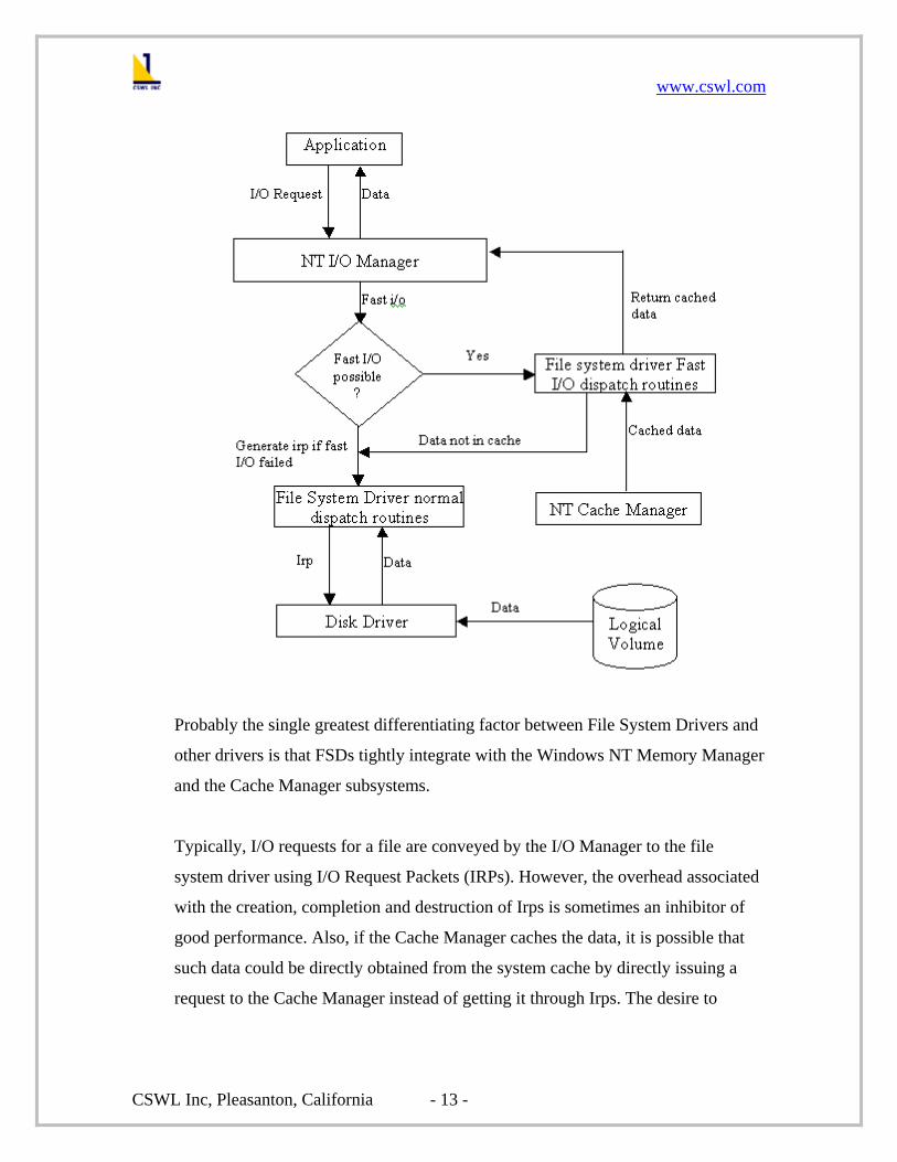
Probably the single greatest differentiating factor between File System Drivers and
other drivers is that FSDs tightly integrate with the Windows NT Memory Manager
and the Cache Manager subsystems.
Typically, I/O requests for a file are conveyed by the I/O Manager to the file
system driver using I/O Request Packets (IRPs). However, the overhead associated
with the creation, completion and destruction of Irps is sometimes an inhibitor of
good performance. Also, if the Cache Manager caches the data, it is possible that
such data could be directly obtained from the system cache by directly issuing a
request to the Cache Manager instead of getting it through Irps. The desire to
www.cswl.com
CSWL Inc, Pleasanton, California - 14 -
achieve better system performance led to the creation of Fast I/O method for
obtaining cached data in the Windows NT environment.
Fast I/O is only performed if the file stream is cached and it is always a
synchronous operation. An interesting point to note is that if data transfer is not
possible using the Fast i/o path for a specific operation on a file stream, the I/O
Manager simply resorts to using the standard IRP method to retry the operation.
Whenever, the I/O Manager receives a user request to access an open file stream,
the I/O Manager invokes the Fast I/O entry point. The Fast I/O entry point is of
type BOOLEAN. This allows the FSD to inform the I/O Manager about whether it
was able to process the request. If the FSD was able to completely process the
request in its Fast I/O routine, the FSD returns TRUE as the status of the Fast I/O
routine. This results in the I/O Manager completing the request back to the
requestor. If the FSD could not completely process the request, it returns FALSE
from its Fast I/O routine. In this case, the I/O Manager builds an IRP that describes
the I/O request and calls the FSD at the appropriate dispatch entry point. The FSD
then retrieves the data from the disk.
Thread context management
File System Drivers (FSDs) are always logically located at the top of a Windows
NT stack of drivers. Thus a file system driver will always be called in the context
of the thread making the request. This guarantee makes it possible for file system
drivers to use Neither I/O for describing requests. Implementing Neither I/O allows
a file system driver to manipulate data by using the requestor’s virtual address.
Thus, I/O requests for FSDs must be passed to the FSD in the context of the thread
originally initiating the request. If a filter driver changes the context of the request,
by sending a request off to be processed by a worker thread, the FSD will fail to
work as the address it references in the user space is not valid in this arbitrary
thread context.

www.cswl.com
CSWL Inc, Pleasanton, California - 15 -
This will result in a page fault, as the FSD will be referring to non-existent
memory. To avoid this catastrophe, the filter driver must ensure that the kernel
virtual address for the requestor’s buffer is usable in an arbitrary thread context.
This is accomplished by changing the buffering method from Neither I/O to Direct
I/O. In the case of Direct I/O; the I/O Manager automatically builds a Memory
Descriptor List (MDL) describing the caller’s buffer. MDL is a structure that keeps
track of the physical pages associated with a virtual buffer. The MDL consists of a
header describing the virtual buffer, followed by an array that lists the physical
pages associated with the buffer. Given, a virtual address within the buffer, it is
possible to determine the corresponding physical page.
Therefore if a filter decides that it requires the requestor’s buffer to be usable in an
arbitrary thread context, it is required to perform the following steps:
• Create an MDL to describe the requestor’s buffer.
• Check the pages that comprise the buffer for accessibility and lock the
pages into physical memory.

www.cswl.com
CSWL Inc, Pleasanton, California - 16 -
• Map the requestor’s buffer described by the MDL into kernel virtual
address space.
The pointer to the MDL is supplied to the FSD in the IRP (at IrpàMdlAddress).
Why do we need guaranteed I/O?
Many real time applications may require atleast a bare minimum of the disk
bandwidth to function properly. For example, Media players always require a
minimum disk bandwidth for it to function properly (ensure a smooth transfer
between the frames) failing which the transition between frames will be abrupt.
But Windows NT does not provide any native support for any such guarantees on
disk I/O. The bandwidth enjoyed by an application is not consistent in most cases
and it tends to reduce with the number of disk hungry applications. Hence there is
no guarantee that the applications continue to get their required bandwidth. It
would require a specially written driver to incorporate this feature on the Windows
NT operating system.
Computing disk bandwidth
Disk bandwidth is defined as the number of bytes that can be accessed from a disk
in a time quantum. The bandwidth of the disk is calibrated by timing all the Irps
that make disk access.
The filter driver determines the time taken to service these Irps by setting a
“Completion Routine” before dispatching them to the file system driver. Once this
completion routine is set the filter is notified by the I/O Manager when the Irp is
completed. This is done for all the Irps that read from the disk so that any
differences in the bandwidth calculations are averaged out over a period of time.

www.cswl.com
CSWL Inc, Pleasanton, California - 17 -
Challenges in providing guaranteed I/O
The whole idea of trying to guarantee I/O requests in Windows NT evolves around
the estimation of disk bandwidth. Bandwidth, here is the number of bytes accessed
from the disk in a time quantum. The primary challenge in providing guaranteed
I/O is devising a reliable mechanism to estimate or predict the time taken to service
a given number of bytes by the file system driver. There are a number of factors
that affect the time taken to service an IRP.
The following are a few main factors among them:
Bandwidth Variation
Guaranteeing I/O for an application greatly depends on the estimation of disk
bandwidth. The bandwidth of the disk is not a constant value, but keeps varying
i.e., the time taken to service "n" bytes is not always a constant. Thus it may be
inferred that the number of bytes that are accessed from the disk is not the only
criterion deciding the disk bandwidth. A host of other factors may also play a role
in deciding the bandwidth. Thus a proper and reliable estimate of the bandwidth
can be obtained only after a considerable number of reads are timed. This may
average out the differences in estimating the bandwidth.
The physical file stream (FAT or NTFS) plays a role in how requests are
processed:
The File system drivers corresponding to the FAT or the NTFS file systems
internally maintain their own queue of the IRPs that it needs to process. This
queuing can affect the time taken for to complete an IRP.
The fragmentation of the disk also affects the transfer rate of the disk: When
fragmented, the files in the file system are written in small pieces on the hard disk,
thus scattering the available disk space. Disk fragmentation increases access time
and reduces file system efficiency. Performance can suffer if the file becomes

www.cswl.com
CSWL Inc, Pleasanton, California - 18 -
severely fragmented. If the file is highly fragmented, there will be a considerable
variation in the seek rate. This variation would reduce the disk bandwidth.
Handling Fast I/O:Fast I/O is performed if the file stream is cached and it is
always a synchronous operation. Fast I/O is a procedure-based interface between
the I/O Manager and the file system drivers. The Fast I/O interface makes it
possible for FSDs to process certain operations, including some read and write
operations, without the use of Irps.
In Fast I/O, request parameters are passed from the I/O Manager to the FSD as
function parameters. Because the FSD is called in the context of the requesting
thread, the parameters that are passed in are all that the FSD requires to process the
request.
Guaranteeing Fast I/o is one of the major challenges in providing guaranteed I/O
for an application. Since the I/O Manager does not create an irp in this case, it is
virtually impossible to guarantee Fast I/O calls.
Handling System Irps:Systems Irps are those that are generated by the system to
perform certain disk activities. System Irps are mostly generated for a paging
operation. Such Irps have if not handled properly by us, might result in
unpredictable performance. Moreover, these system Irps do use some amount of the
disk bandwidth. This is done at the expense of the bandwidth that has been
allocated to some other application. Therefore the application might not be getting
its share of the bandwidth when there is a sudden increase in the number of such
system Irps.
www.cswl.com
CSWL Inc, Pleasanton, California - 19 -
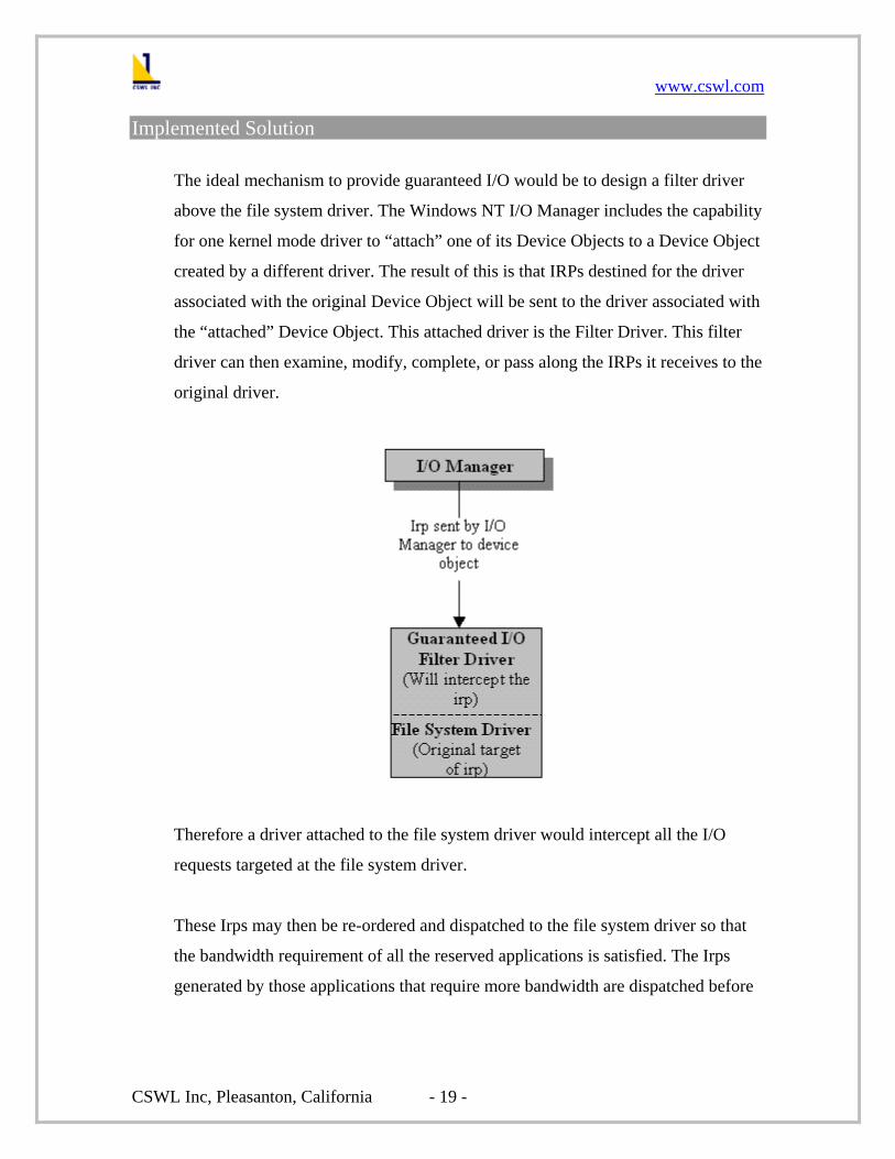
Implemented Solution
The ideal mechanism to provide guaranteed I/O would be to design a filter driver
above the file system driver. The Windows NT I/O Manager includes the capability
for one kernel mode driver to “attach” one of its Device Objects to a Device Object
created by a different driver. The result of this is that IRPs destined for the driver
associated with the original Device Object will be sent to the driver associated with
the “attached” Device Object. This attached driver is the Filter Driver. This filter
driver can then examine, modify, complete, or pass along the IRPs it receives to the
original driver.
Therefore a driver attached to the file system driver would intercept all the I/O
requests targeted at the file system driver.
These Irps may then be re-ordered and dispatched to the file system driver so that
the bandwidth requirement of all the reserved applications is satisfied. The Irps
generated by those applications that require more bandwidth are dispatched before

www.cswl.com
CSWL Inc, Pleasanton, California - 20 -
the Irps from other applications. This ensures that more requests of a guaranteed
application are processed when compared to a non-guaranteed application.
How filter gets control
Whenever any user's i/o request is received by the i/o manager for a file residing on
a mounted logical volume, the I/O Manager normally forwards the request to the
file system driver managing the mounted logical volume.
Before forwarding the request, however, the I/O Manager also checks to see if any
other device object has layered itself over the device object representing the
mounted logical volume and redirects the request to that device object, which is at
the top of the layered list of device objects. Therefore, the filter driver module
intercepts the I/O before it reaches the file system.
Hence once the filter is attached to the file system that is to be guaranteed, the filter
intercepts all the Irps that the I/O manager sends down to the FSD. The filter may
then manipulate these Irps and then dispatch then to the underlying FSD.
Note that the file system driver has no idea that some other filter driver is layered
above it. It behaves as if the I/O Manager has sent the user request directly to it.

www.cswl.com
CSWL Inc, Pleasanton, California - 21 -
The figure above shows the flow of IRP through the system after the Guaranteed
I/O filter driver is attached to the File system driver.
Step 1. The I/O manager creates the IRP for the operation that it needs to do. It fills
the stack location corresponding to the driver that is at the top of the layer (in this
case our filter).
Step 2. The filter on receiving the IRP does some processing that needs to be done.
Step 3. The filter then returns the IRP the I/O manager copying its stack to the
lower drivers stack location.
Step 4. The I/O manager then passed on the IRP to the next driver in the order (this
case it is the FSD).
Step 5. The lower level driver now processes the IRP. The lower level driver uses
its own stack in the IRP for the processing.

www.cswl.com
CSWL Inc, Pleasanton, California - 22 -
Step 6. The lower level driver (FSD) returns the IRP back to the I/O manager. The
I/O manager then releases whatever resource was allocated to the IRP.
What the filter does?
The filter driver determines the total bandwidth of the disk. This is accomplished
by generating read requests and estimating the time taken to service these IRPs.
The total bandwidth is split into two pools – Guaranteed Bandwidth Pool and the
Non Guaranteed Bandwidth Pool. As the names suggest, the applications that have
reserved bandwidth eat into the Guaranteed Bandwidth Pool and the unreserved
applications use the Non Guaranteed Bandwidth Pool.
The driver traps the Irps intended for the file system driver. These Irps are then
dispatched based on the bandwidth requirements of the applications. The
bandwidth required by each application is specified through a User Interface. The
bandwidth is specified as the number of bytes to be accessed by the application in
“n” seconds (referred to as a time quantum hereafter).
The filter keeps track of the time quantum of all the applications and refreshes
them. The time quantum of an application begins as soon as the application starts.
www.cswl.com
CSWL Inc, Pleasanton, California - 23 -
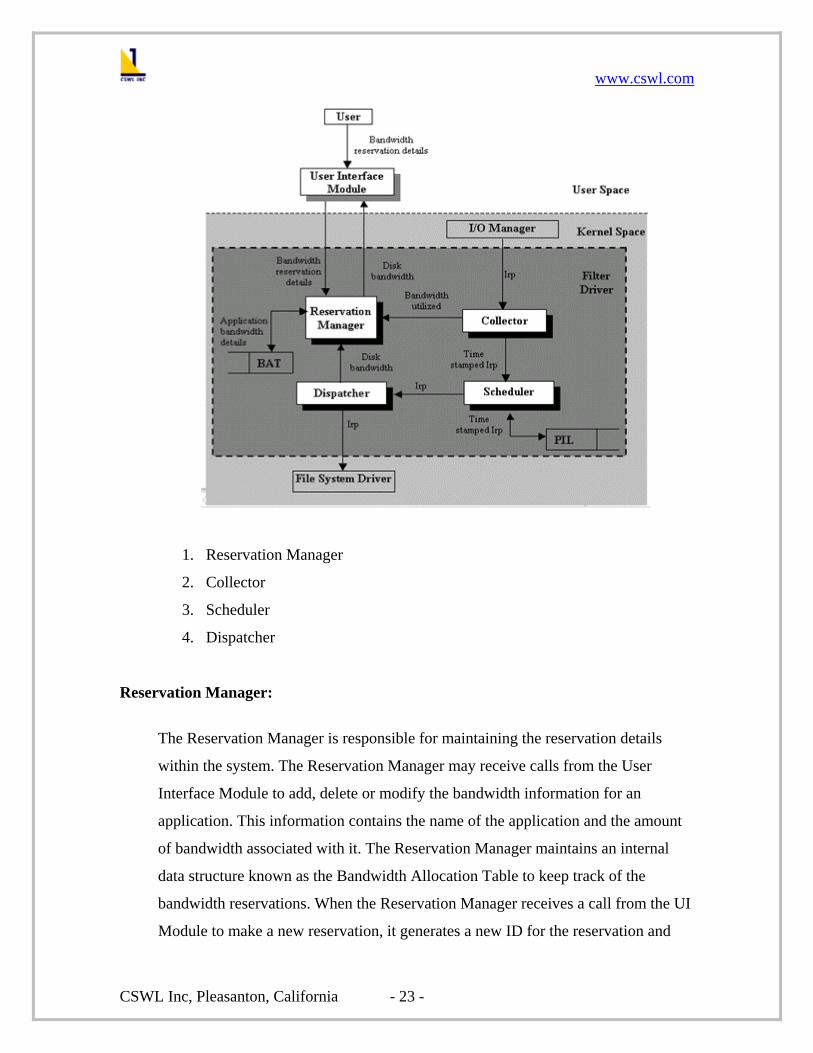
1. Reservation Manager
2. Collector
3. Scheduler
4. Dispatcher
Reservation Manager:
The Reservation Manager is responsible for maintaining the reservation details
within the system. The Reservation Manager may receive calls from the User
Interface Module to add, delete or modify the bandwidth information for an
application. This information contains the name of the application and the amount
of bandwidth associated with it. The Reservation Manager maintains an internal
data structure known as the Bandwidth Allocation Table to keep track of the
bandwidth reservations. When the Reservation Manager receives a call from the UI
Module to make a new reservation, it generates a new ID for the reservation and

www.cswl.com
CSWL Inc, Pleasanton, California - 24 -
makes an entry in the BAT. The reservation manager also stores in the BAT an
entry corresponding to the non-guaranteed bandwidth pool, which will be used by
all the unreserved applications.
The reservation for an application is valid only when it starts. Till then the
unreserved applications are allowed to eat into this bandwidth. The filter receives a
notification whenever a process is created or deleted. This is accomplished by
registering a "Process Notification Routine" with the system. Once such a routine
has been registered, the system will invoke it whenever a process is either created
or deleted. The bandwidth used by a reserved application is released to the non-
guaranteed pool when it exits. Thus the reservation is valid only during the lifetime
of an application. This ensures that there are no "bandwidth leaks" within the
system.
Collector:
The basic function of the collector is to trap all IRPs that are sent by the I/O
Manager to the filter. On receiving an IRP from the IO Manager, the collector
determines the name of the application that issued the request. It then passes this
information to the Reservation Manager, which updates the BAT with the number
of bytes being accessed by the irp. The Collector then time stamps this IRP with the
time before which it has to be dispatched. The time stamped irp is then sent to the
Scheduler where it is queued in a list.
Scheduler:
The Scheduler is a separate thread that dispatches Irps to the Dispatcher. The
Scheduler maintains a data structure Pending IRP List (hereafter referred to as the
PIL) to which the Collector adds the Irps. Based on the time stamp on the irp, the
scheduler removes it from the list and sends it to the Dispatcher. If the time stamp
of the IRP corresponds to the next time-quantum of the application, the Scheduler
www.cswl.com
CSWL Inc, Pleasanton, California - 25 -
goes into a wait state after setting a timer. The timer is set to expire at the
beginning of the next time quantum.
The Scheduler does processing only on receiving a notification. The Scheduler is
notified whenever a new irp is added to the PIL or by a timer object, which was set
by the Scheduler.
Dispatcher:
The Dispatcher receives IRPs that are to be dispatched immediately from the
Scheduler and sends them to the underlying File System Driver. The dispatcher is
also responsible for estimating the bandwidth of the disk. The dispatcher
accomplishes this by timing each irp that is serviced.
Scheduling logic of the filter using time stamps
Bandwidth is defined as the number of bytes that are serviced in a time quantum of
‘n’ seconds. The scheduling of the Irps is based on the time stamps affixed on the
Irps. The Irps are time stamped based on the bandwidth used by the application in a
time quantum.
The time quantum of an application begins when the application starts. If the
bandwidth for an application is not satisfied for the current time quantum, the time
taken to service the irp is estimated. If the estimated time is within the current time
quantum of the application, the irp is dispatched immediately to the FSD. If this
estimated exceeds the current time quantum, the irp is time stamped to the next
time quantum. This time stamped irp is added to the PIL.
If the application has already utilized its allocated bandwidth, the irp is time
stamped to the next time quantum and is added to the PIL. The bandwidth utilized
by the application for the current time quantum is reset.

www.cswl.com
CSWL Inc, Pleasanton, California - 26 -
A separate thread removes the time stamped Irps from the PIL and dispatches them
to the FSD. The thread begins processing the PIL on receiving a notification. This
may either be due to an addition of a new irp to the PIL or by a timer set by the
thread.
The Irps are dispatched based on their respective time stamp. If the time stamp
indicated that the irp has to be dispatched in the current time quantum, the irp is
removed from the PIL and is dispatched to the FSD. If the time stamp on the irp
does not correspond to the current time quantum of the application; the thread sets
a timer and goes into a “wait state”. The timer is set to expire at the beginning of
the next time quantum of the application.
Installation, testing and debugging
Installation:
Installing device drivers on Windows NT is extremely simple. The entire process
consists of only two steps:
1. Copy the necessary files to the system.These files include the driver
executable image (.sys) file, as well as any other files (such as file
containing configuration information) that are required by the driver.
2. Create the necessary Registry entries:These entries indicate when the
driver is to be started, and also store any driver specific or device specific
information that the driver may need during its initialization process. Each
driver in Windows NT must have its own key in the Registry, named with
the driver’s name, under the
HKEY_LOCAL_MACHINE\SYSTEM\CurrentControlSet\Services key.
Briefly, the value entries relevant to driver startup that may appear under a
driver’s Services key are as follows:

www.cswl.com
CSWL Inc, Pleasanton, California - 27 -
• Type:This value indicates the type of component (driver, files
system, or application) that this represents.
• Start:This value tells the system whether it should attempt to start
this driver during system startup and, if so, during what phase of
system startup it should attempt it.
• Group:This value allows the driver writer to specify a specific
startup order for their driver order within a given system startup
phase.
• Tag:This value allows us to establish a specific order in a particular
startup group.
• Error Control:This value indicates what action the system should
take if it attempts to start a driver but fails.
• DependOnGroup/DependOnService:This value identifies a
prerequisite group or a specific driver on which the driver depends.
• Image Path:This value contains the path to the driver image file.
• Display Name:This is the text name of the driver to be displayed.
Testing:
The following test cases can be employed to evaluate the functioning of the
Guaranteed I/O filter driver.
Test I
Many disk intensive applications were run simultaneously on the disk on which the
guarantees are made.
Now the media player is run making bandwidth reservations so that it runs
smoothly.
Test II

www.cswl.com
CSWL Inc, Pleasanton, California - 28 -
A CPU intensive program (some program that does a tight loop) is run.
Now the media player is run making bandwidth reservations so that it runs
smoothly.
Test III
Both test I and Test II are performed together
Now the media player is run making bandwidth reservations so that it runs
smoothly.
Debugging:
Debugging kernel mode drivers is a slow process. There are a few debuggers that
may be used to debug kernel mode drivers. The most prominent among them are
WinDbg and SoftICE.
About WinDbg:
The standard remote debugger that is supplied as part of the Windows NT SDK is
WinDbg. WinDbg is a full-featured multi-window debugger. It supports source-
level debugging in either C or assembler language. Breakpoints of all types (static,
conditional, and the like) may be set using the driver’s source code. Using WinDbg
it is possible to perform single-step program execution (stepping either into or over
called functions), examine local variables and change them.
About SoftICE
SoftICE combines the power of a hardware debugger with the ease of use of a
symbolic debugger. It provides hardware-like breakpoints and sticky breakpoints
that follow the memory as the operating system discards, reloads, and swaps pages.
SoftICE displays your source code as you debug, and lets you access your local and
global data through their symbolic names.

www.cswl.com
CSWL Inc, Pleasanton, California - 29 -
SoftICE consists of the SoftICE kernel-mode debugger and the Symbol Loader
utility. The SoftICE debugger (SoftICE) is an advanced, all-purpose debugger that
can debug virtually any type of code including interrupt routines, processor level
changes, and I/O drivers. The Symbol Loader utility loads the debug information
for your module into SoftICE, maintains the SoftICE initialization settings, and lets
you save the contents of the SoftICE history buffer to a file.
Hints and tips regarding driver debugging:
The section contains the most random collection of hints and tips regarding driver
debugging.
Displaying output messages:
One of the simplest ways to debug kernel mode drivers is to display appropriate
output messages at whenever necessary in the driver. This allows us to keep track
of the control flow of the driver and trace the bugs and other shortcomings in the
driver.
Asserting Assumptions:
A well known technique for writing solid code is the use of the ASSERT () macro.
This function allows you to check, at runtime, that your assumptions are true.
Where to go from here?
• Guaranteeing I/O for multiple disks
• Porting to Windows 2000
• Improve the bandwidth estimation

www.cswl.com
CSWL Inc, Pleasanton, California - 30 -
References
Web site references:
http://www.eu.microsoft.com/hwdev/ddk/ddk40.htm
http://www.intec.es/ddk
http://www.sysinternals.com/
News Groups and Mailing Lists:
• Comp.os.ms-windows.programmer.nt.kernel-mode
• Microsoft.public.win32.programmer.kernel
Books:
• Inside Windows NT – David Solomon
• The Windows NT Device Driver development – Peter G. Viscarola and W.
Anthony Mason
• Windows NT File System Internals – Rajeev Nagar
• The Windows NT Device Driver book – Art Baker
----------------------------------------------------------------------------------------------------------- Copyright Notice: 2002 California Software Labs. All rights Reserved. The contents on the document are not to be reproduced or duplicated in any form or kind, either in part or full, without the written permission of California Software labs. Product and company names mentioned here in are the trademarks of their respective companies.