io-link - omron · 2019-11-02 · io-link 327 gx-ilm@, nx-ilm@ io-link io-link makes communication...
TRANSCRIPT

327IO-Link
GX-ILM@, NX-ILM@
IO-Link
IO-Link makes communication down to the sensor level visible
• Machine downtime can be reduced• Abnormality detection for shortest recovery• Condition monitoring for predictive maintenance• Individual identification for reduction of man hours• Master unit with screw-less terminal block or with
IP67 protection class for watery and dusty environ-ments
• Up to 8 sensors can be connected with one IO-Link master unit
• Photoelectric and Proximity sensors
System configuration
NX7/NJ seriesMachine automation controller
Sysmac Studio
IoT
MES/ERP, SQL database server
FACTORY AUTOMATION NETWORK
REAL-TIME MACHINE CONTROL
INTELLIGENT SENSORS/ACTUATORS
GX-series IO-Linkmaster unit
NX-series IO-Linkmaster unit
Photoelectric andProximity sensors
Up to 8 sensors Up to 4 sensors
328 Remote I/O
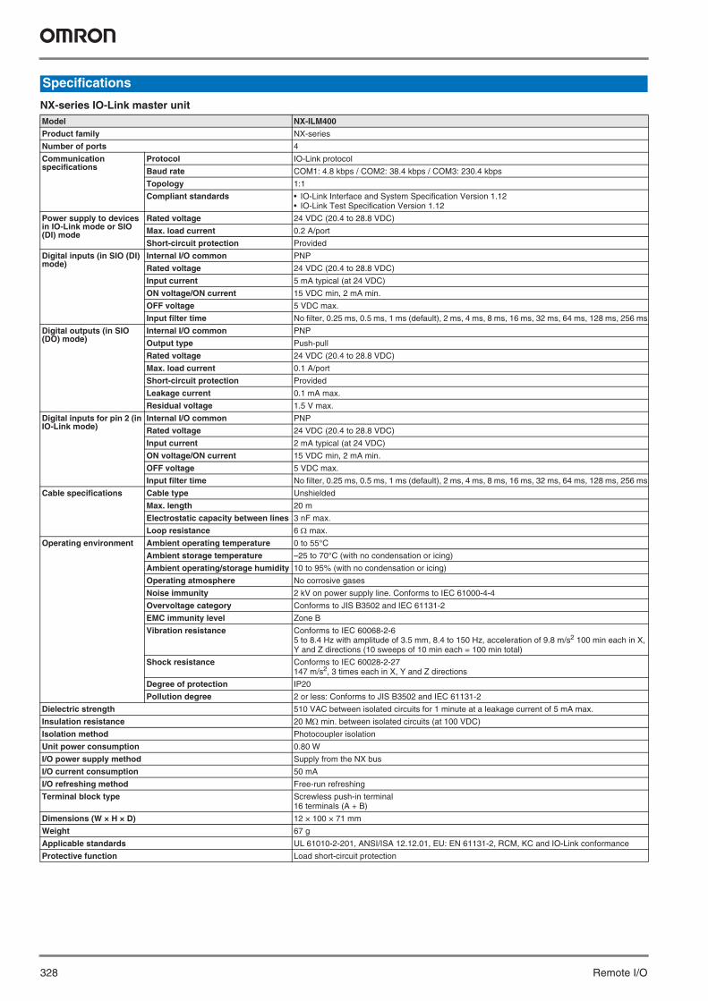
NX-series IO-Link master unit
Specifications
Model NX-ILM400
Product family NX-series
Number of ports 4
Communicationspecifications
Protocol IO-Link protocol
Baud rate COM1: 4.8 kbps / COM2: 38.4 kbps / COM3: 230.4 kbps
Topology 1:1
Compliant standards • IO-Link Interface and System Specification Version 1.12• IO-Link Test Specification Version 1.12
Power supply to devices in IO-Link mode or SIO (DI) mode
Rated voltage 24 VDC (20.4 to 28.8 VDC)
Max. load current 0.2 A/port
Short-circuit protection Provided
Digital inputs (in SIO (DI) mode)
Internal I/O common PNP
Rated voltage 24 VDC (20.4 to 28.8 VDC)
Input current 5 mA typical (at 24 VDC)
ON voltage/ON current 15 VDC min, 2 mA min.
OFF voltage 5 VDC max.
Input filter time No filter, 0.25 ms, 0.5 ms, 1 ms (default), 2 ms, 4 ms, 8 ms, 16 ms, 32 ms, 64 ms, 128 ms, 256 ms
Digital outputs (in SIO (DO) mode)
Internal I/O common PNP
Output type Push-pull
Rated voltage 24 VDC (20.4 to 28.8 VDC)
Max. load current 0.1 A/port
Short-circuit protection Provided
Leakage current 0.1 mA max.
Residual voltage 1.5 V max.
Digital inputs for pin 2 (in IO-Link mode)
Internal I/O common PNP
Rated voltage 24 VDC (20.4 to 28.8 VDC)
Input current 2 mA typical (at 24 VDC)
ON voltage/ON current 15 VDC min, 2 mA min.
OFF voltage 5 VDC max.
Input filter time No filter, 0.25 ms, 0.5 ms, 1 ms (default), 2 ms, 4 ms, 8 ms, 16 ms, 32 ms, 64 ms, 128 ms, 256 ms
Cable specifications Cable type Unshielded
Max. length 20 m
Electrostatic capacity between lines 3 nF max.
Loop resistance 6 max.
Operating environment Ambient operating temperature 0 to 55°C
Ambient storage temperature –25 to 70°C (with no condensation or icing)
Ambient operating/storage humidity 10 to 95% (with no condensation or icing)
Operating atmosphere No corrosive gases
Noise immunity 2 kV on power supply line. Conforms to IEC 61000-4-4
Overvoltage category Conforms to JIS B3502 and IEC 61131-2
EMC immunity level Zone B
Vibration resistance Conforms to IEC 60068-2-65 to 8.4 Hz with amplitude of 3.5 mm, 8.4 to 150 Hz, acceleration of 9.8 m/s2 100 min each in X, Y and Z directions (10 sweeps of 10 min each = 100 min total)
Shock resistance Conforms to IEC 60028-2-27147 m/s2, 3 times each in X, Y and Z directions
Degree of protection IP20
Pollution degree 2 or less: Conforms to JIS B3502 and IEC 61131-2
Dielectric strength 510 VAC between isolated circuits for 1 minute at a leakage current of 5 mA max.
Insulation resistance 20 M min. between isolated circuits (at 100 VDC)
Isolation method Photocoupler isolation
Unit power consumption 0.80 W
I/O power supply method Supply from the NX bus
I/O current consumption 50 mA
I/O refreshing method Free-run refreshing
Terminal block type Screwless push-in terminal16 terminals (A + B)
Dimensions (W × H × D) 12 × 100 × 71 mm
Weight 67 g
Applicable standards UL 61010-2-201, ANSI/ISA 12.12.01, EU: EN 61131-2, RCM, KC and IO-Link conformance
Protective function Load short-circuit protection

IO-Link 329
GX-series IO-Link master unitModel GX-ILM08C
Product family GX-series
Number of ports 8
Communicationspecifications
Protocol IO-Link protocol
Baud rate COM1: 4.8 kbps / COM2: 38.4 kbps / COM3: 230.4 kbps
Topology 1:1
Compliant standards • IO-Link Interface and System Specification Version 1.12• IO-Link Test Specification Version 1.12
Power supply to devices in IO-Link mode or SIO (DI) mode
Rated voltage 24 VDC (20.4 to 26.4 VDC)
Max. load current 0.2 A/port
Short-circuit protection Provided
Digital inputs (in SIO (DI) mode)
Internal I/O common PNP
Rated voltage 24 VDC (20.4 to 26.4 VDC)
Input current 5 mA typical (at 24 VDC)
ON voltage/ON current 15 VDC min, 5 mA min.
OFF voltage 5 VDC max.
Input filter time No filter, 0.25 ms, 0.5 ms, 1 ms (default), 2 ms, 4 ms, 8 ms, 16 ms, 32 ms, 64 ms, 128 ms, 256 ms
Digital outputs (in SIO (DO) mode)
Internal I/O common PNP
Output type Push-pull
Rated voltage 24 VDC (20.4 to 26.4 VDC)
Max. load current 0.3 A/port
Short-circuit protection Provided
Leakage current 0.1 mA max.
Residual voltage 1.5 V max.
Digital inputs for pin 2 (in IO-Link mode)
Internal I/O common PNP
Rated voltage 24 VDC (20.4 to 26.4 VDC)
Input current 2 mA typical (at 24 VDC)
ON voltage/ON current 15 VDC min, 2 mA min.
OFF voltage 5 VDC max.
Input filter time No filter, 0.25 ms, 0.5 ms, 1 ms (default), 2 ms, 4 ms, 8 ms, 16 ms, 32 ms, 64 ms, 128 ms, 256 ms
Cable specifications Cable type Unshielded
Max. length 20 m
Electrostatic capacity between lines 3 nF max.
Loop resistance 6 max.
Operating environment Ambient operating temperature –10 to 55°C
Ambient storage temperature –25 to 65°C
Ambient operating/storage humidity 25 to 85% (with no condensation)
Operating atmosphere No corrosive gases
Noise immunity 2 kV on power supply line. Conforms to IEC 61000-4-4
Vibration resistance Malfunction: 10 to 60 Hz with amplitude of 0.7 mm, 60 to 150 Hz and 50 m/s2 for 80 min each in X, Y and Z directions
Shock resistance 150 m/s2 with amplitude of 0.7 mm
Degree of protection IP67
Dielectric strength 600 VAC between isolated circuits
Insulation resistance 20 M min. between isolated circuits
Isolation method Photocoupler isolation
Unit power consumption 60 mA
I/O power supply method Supplied from the power supply connector
I/O current consumption 100 mA
Mounting M5 screw mounting
Mounting strength 100 N
Communications connector strength 30 N
Connectors EtherCAT communications connectors: M12 (D-coding, female) × 2Power supply connector: M12 (A-coding, male) × 1I/O connectors: M12 (A-coding, female) × 8*1
*1 Confirms to Class A when used as an IO-Link connector.
Screw tightening torque*2
*2 For Smartclick connectors, insert the connector all the way and turn it approx. 1/8 of a turn. Torque management is not required.
Round connectors (communications connector, power supply and I/O): 0.39 to 0.49 N·mM5 (unit mounted from the front): 1.47 to 1.96 N·mCover for node address setting switches: 0.4 to 0.6 N·m
Dimensions (W × H × D) 175 × 33 × 60 mm*3
*3 The height is 49.1 mm when the connectors are included.
Weight 430 g
Applicable standards EU: EN 61131-2, RCM, KC, IO-Link conformance and EtherCAT conformance
Protective function Load short-circuit protection

330 Remote I/O
Terminal wiring
NX-ILM400
Circuit layout
NX-ILM400
Left-sideNX bus
connector
Terminalblock L+
IO-LinkcircuitsC/Q
DI
I/O power supply +I/O power supply -
I/O power supply +I/O power supply -
Right-sideNX busconnector
Inte
rnal
circ
uits
L-
IO-Link master unit
NX-ILM004A1 B1
A8 B8
IO-Link sensorwith DI input
IO-Link sensorwithout DI input
14
2
3
14
3
Brown
Black
White
Blue
Brown
Black
Blue
P1_C/Q
P3_C/Q P4_C/Q
P1_DI
P3_DI P4_DI
P1_L+
P3_L+P3_L-
P1_L-P2_L+
P4_L+P4_L-
P2_L-
P2_DIP2_C/Q
GX-ILM08C
IN communicationsconnector
OUT communicationsconnector
Powersupplyconnector
Unit power supply24 VUnit power supply0 V
I/O powersupply 0 V
Internalcircuits
Isolationcircuit
Non-isolatedpower supply
circuits
Non-isolatedpower supply
circuits
IO-Linkcircuits
I/Oconnector 1
I/Oconnector 8
L+C/QDIL-
L+C/QDIL-
I/O powersupply 24 V

IO-Link 331
NX-ILM400
GX-ILM08C
Nomenclature/Dimensions
Symbol Name Description
A NX bus connector This connector is used to connect each unit.
B Indicators The indicators show the current operating status of the unit.
C Terminal block The terminal block is used to connect external devices.The number of terminals depends on the type of unit.
A
C
B
80.1
71
104.
5
100
14.1
65.2
12.0
1.5
1.5
Symbol Name Description
A EtherCAT communications connector, IN EtherCAT cable connection: IN sideM12 connector (D-coding, female)
B EtherCAT communications connector, OUT EtherCAT cable connection: OUT sideM12 connector (D-coding, female)
C Power supply connector Connects to power supply unit and I/O power supply cableM12 connector (A-coding, male)
D I/O connectors Connect to IO-Link sensor cables (IO-Link connector type: Class A)M12 connectors (A-coding, female)
E Node address setting switches Used to set the EtherCAT node address.
F Status indicators Indicate the current status of the EtherCAT slave unit.(RUN, ERR, L/A IN, L/A OUT, UNIT PWR and I/O PWR)
G I/O indicators Indicate the I/O status (C/E and C/Q).
H Mounting holes Used to mount the unit with M5 screws.
D
A
D
B
H
FC
G
H
E
60
175
60
175

332 Remote I/O
IO-Link master unit
Accessories
Ordering information
Item IO-Link ports Connection type Degree of protection Model Appearance
NX-series IO-Link master unit*1
*1 EtherCAT communication coupler unit NX-ECC2@@ is necessary for the system configuration.
4 Screwless push-in (NX-TBA162) IP20 NX-ILM400
GX-series IO-Link master unit 8 M12 Smartclick connector IP67 GX-ILM08C
Applicable models Item Specifications Model
NX-ILM400 Terminal block coding pins Pins for 10 units (terminal block: 30 pins, unit: 30 pins) NX-AUX02
Terminal block (replacement front con-nector)
16 wiring terminals (A + B) NX-TBA162
End cover Included with communication coupler NX-END01
GX-ILM08C Power supply T-joint connector Connector used when branching a GX-series IO-Link master unit power supply.
XS5R-D427-5
Waterproof cover for M12 connectors (female). When you use this waterproof cover, you can maintain the IP67 protec-tive structure. Can be mounted on an EtherCAT connector or I/O connector
M12 threaded waterproof cover, Screw-type connector, material: brass/nickel plated
XS2Z-22
M12 Smartclick waterproof cover, Smartclick connector, material: PBT XS5Z-11
Torque wrench Tool for tightening M12 threaded connectors XY2F-0004
EtherCAT communication cables(Cable with connectors on both ends, Rugged type, Shield strengthening ca-ble, AWG22, 2-pair cable, Color: Black, Manufacturer: OMRON)
Smartclick connectorM12 straight/M12 straight
0.5 m XS5W-T421-BM2-SS
1 m XS5W-T421-CM2-SS
2 m XS5W-T421-DM2-SS
3 m XS5W-T421-EM2-SS
5 m XS5W-T421-GM2-SS
10 m XS5W-T421-JM2-SS
Smartclick connectorM12 straight/RJ45 straight
0.5 m XS5W-T421-BMC-SS
1 m XS5W-T421-CMC-SS
2 m XS5W-T421-DMC-SS
3 m XS5W-T421-EMC-SS
5 m XS5W-T421-GMC-SS
10 m XS5W-T421-JMC-SS
Power cables(Socket on one cable side)
Smartclick connectorM12 straight
1 m XS5F-D421-C80-F
2 m XS5F-D421-D80-F
3 m XS5F-D421-E80-F
5 m XS5F-D421-G80-F
10 m XS5F-D421-J80-F

IO-Link 333
Photoelectric sensor
Slit (Not provided with through-beam sensors. Order a slit separately if required)
Reflector (Required for retro-reflective sensors. Not provided with the sensor. Order a reflector separately)
Sensing method Sensing distance Connection method Baud rate Model (PNP) Appearance
Through-beam(emitter + receiver)*1
*1 Through-beam sensors are normally sold in sets that include both the emitter and receiver. Refer to “IO-Link catalogue (Y212-E1)” for separate items.
15 m Pre-wired (2 m) COM2 E3Z-T81-IL2 2M
Pre-wired M12 connector E3Z-T81-M1TJ-IL2 0.3M
Standard M8 connector E3Z-T86-IL2
Pre-wired (2 m) COM3 E3Z-T81-IL3 2M
Pre-wired M12 connector E3Z-T81-M1TJ-IL3 0.3M
Standard M8 connector E3Z-T86-IL3
Retro-reflective with MSR function*2
*2 The reflector is sold separately. Select the reflector model most suited to the application.
4 m*3
*3 The sensing distance specified is possible when the E39-R1S is used. The minimum required distance between the sensor and reflector is 100 mm.
Pre-wired (2 m) COM2 E3Z-R81-IL2 2M
Pre-wired M12 connector E3Z-R81-M1TJ-IL2 0.3M
Standard M8 connector E3Z-R86-IL2
Pre-wired (2 m) COM3 E3Z-R81-IL3 2M
Pre-wired M12 connector E3Z-R81-M1TJ-IL3 0.3M
Standard M8 connector E3Z-R86-IL3
Diffusive-reflective 1 m Pre-wired (2 m) COM2 E3Z-D82-IL2 2M
Pre-wired M12 connector E3Z-D82-M1TJ-IL2 0.3M
Standard M8 connector E3Z-D87-IL2
Pre-wired (2 m) COM3 E3Z-D82-IL3 2M
Pre-wired M12 connector E3Z-D82-M1TJ-IL3 0.3M
Standard M8 connector E3Z-D87-IL3
90 mm(narrow beam)
Pre-wired (2 m) COM2 E3Z-L81-IL2 2M
Pre-wired M12 connector E3Z-L81-M1TJ-IL2 0.3M
Standard M8 connector E3Z-L86-IL2
Pre-wired (2 m) COM3 E3Z-L81-IL3 2M
Pre-wired M12 connector E3Z-L81-M1TJ-IL3 0.3M
Standard M8 connector E3Z-L86-IL3
Slit width Sensing distance E3Z-T@@ Min. detectable object (reference value) Model*1
*1 One set contains slits for emitter and receiver.
0.5 mm dia. 50 mm 0.2 mm dia. E39-S65A
1 mm dia. 200 mm 0.4 mm dia. E39-S65B
2 mm dia. 800 mm 0.7 mm dia. E39-S65C
0.5 × 10 mm 1 m 0.2 mm dia. E39-S65D
1 × 10 mm 2.2 m 0.5 mm dia. E39-S65E
2 × 10 mm 5 m 0.8 mm dia. E39-S65F
Item Sensing distance E3Z-R@@*1
*1 Values in the parentheses indicate the minimum required distance between the sensor and reflector.
Model
Rated value Reference value
Reflector 3 m (100 mm) – E39-R1
4 m (100 mm) – E39-R1S
– 5 m (100 mm) E39-R2
– 2.5 m (100 mm) E39-R9
– 3.5 m (100 mm) E39-R10
Fog preventive coating – 3 m (100 mm) E39-R1K
Small reflector – 1.5 m (50 mm) E39-R3
Reflector tape – 700 mm (150 mm) E39-RS1
– 1.1 m (150 mm) E39-RS2
– 1.4 m (150 mm) E39-RS3

334 Remote I/O
Mounting brackets (Not provided with sensors. Order a mounting bracket separately if required)
Sensor I/O connectors for photoelectric sensors (Models with connectors and pre-wired connectors: A connector is not provided with the sensor. Order a connector separately)
Color mark photoelectric sensor
Item Material Model Appearance
Mounting brackets SUS304 E39-L153*1
*1 Cannot be used for standard connector models with mounting surface on the bottom. In that case, use pre-wired connector models.
E39-L104*1
Horizontal mounting brackets E39-L43*2
*2 Cannot be used for standard connector models.
Horizontal protective cover bracket E39-L142*2
Rear mounting bracket E39-L44
Metal protective cover bracket E39-L98*2
Sensor adjuster(for left to right adjustment)
Easily mounted to the aluminum frame rails of conveyors and easily adjusted.
E39-L150
E39-L151
Compact protective cover bracket(for E3Z only)
E39-L144*2
Size Type Appearance Cable lenght Model
M12 Socket on one cable side Smartclick connectorStraight*1
*1 The connectors will not rotate after they are connected.
2 m XS5F-D421-D80-F
5 m XS5F-D421-G80-F
Smartclick connectorL-shape*1*2
*2 The cable is fixed at an angle of 180º from the sensor emitter/receiver surface.
2 m XS5F-D422-D80-F
5 m XS5F-D422-G80-F
Socket and plug on cable ends*3
*3 Straight type/L-shape type combinations are also available.
Smartclick connectorStraight/Straight*1
2 m XS5W-D421-D81-F
5 m XS5W-D421-G81-F
Smartclick connectorL-shape/L-shape*1*2
2 m XS5W-D422-D81-F
5 m XS5W-D422-G81-F
M8 Socket on one cable side Straight*1 2 m XS3F-M421-402-A
5 m XS3F-M421-405-A
L-shape*1*2 2 m XS3F-M422-402-A
5 m XS3F-M422-405-A
M8 socket/M12 plug Socket and plug on cable ends Smartclick connector M8-M12 conver-sion cable*1
0.2 m XS3W-M42C-4C2-A
Sensing method Sensing distance
Connection method Output Baud rate Model Appearance
Diffusive-reflective (mark detection)
10 ±3 mm M12 connector Push-pull COM2 E3S-DCP21-IL2
COM3 E3S-DCP21-IL3
IO-Link 335
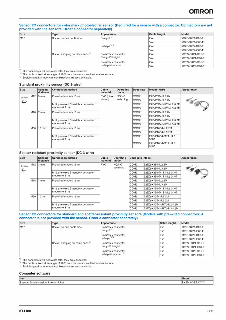
Sensor I/O connectors for color mark photoelectric sensor (Required for a sensor with a connector. Connectors are not provided with the sensors. Order a connector separately)
Standard proximity sensor (DC 3-wire)
Spatter-resistant proximity sensor (DC 3-wire)
Sensor I/O connectors for standard and spatter-resistant proximity sensors (Models with pre-wired connectors: A connector is not provided with the sensor. Order a connector separately)
Computer software
Size Type Appearance Cable lenght Model
M12 Socket on one cable side Straight*1
*1 The connectors will not rotate after they are connected.
2 m XS2F-D421-D80-F
5 m XS2F-D421-G80-F
L-shape*1*2
*2 The cable is fixed at an angle of 180º from the sensor emitter/receiver surface.
2 m XS2F-D422-D80-F
5 m XS2F-D422-G80-F
Socket and plug on cable ends*3
*3 Straight type/L-shape type combinations are also available.
Smartclick connectorStraight/Straight*1
2 m XS5W-D421-D81-F
5 m XS5W-D421-G81-F
Smartclick connectorL-shape/L-shape*1*2
2 m XS5W-D422-D81-F
5 m XS5W-D422-G81-F
Size Sensing distance
Connection method Cable material
Operating mode
Baud rate Model (PNP) Appearance
M12 3 mm Pre-wired models (2 m) PVC (oil-re-sistant)
NO/NC switching
COM2 E2E-X3B4-IL2 2M
COM3 E2E-X3B4-IL3 2M
M12 pre-wired Smartclick connector models (0.3 m)
COM2 E2E-X3B4-M1TJ-IL2 0.3M
COM3 E2E-X3B4-M1TJ-IL3 0.3M
M18 7 mm Pre-wired models (2 m) COM2 E2E-X7B4-IL2 2M
COM3 E2E-X7B4-IL3 2M
M12 pre-wired Smartclick connector models (0.3 m)
COM2 E2E-X7B4-M1TJ-IL2 0.3M
COM3 E2E-X7B4-M1TJ-IL3 0.3M
M30 10 mm Pre-wired models (2 m) COM2 E2E-X10B4-IL2 2M
COM3 E2E-X10B4-IL3 2M
M12 pre-wired Smartclick connector models (0.3 m)
COM2 E2E-X10B4-M1TJ-IL2 0.3M
COM3 E2E-X10B4-M1TJ-IL3 0.3M
Size Sensing distance
Connection method Cable material
Operating mode
Baud rate Model Appearance
M12 3 mm Pre-wired models (2 m) PVC NO/NC switching
COM2 E2EQ-X3B4-IL2 2M
COM3 E2EQ-X3B4-IL3 2M
M12 pre-wired Smartclick connector models (0.3 m)
COM2 E2EQ-X3B4-M1TJ-IL2 0.3M
COM3 E2EQ-X3B4-M1TJ-IL3 0.3M
M18 7 mm Pre-wired models (2 m) COM2 E2EQ-X7B4-IL2 2M
COM3 E2EQ-X7B4-IL3 2M
M12 pre-wired Smartclick connector models (0.3 m)
COM2 E2EQ-X7B4-M1TJ-IL2 0.3M
COM3 E2EQ-X7B4-M1TJ-IL3 0.3M
M30 10 mm Pre-wired models (2 m) COM2 E2EQ-X10B4-IL2 2M
COM3 E2EQ-X10B4-IL3 2M
M12 pre-wired Smartclick connector models (0.3 m)
COM2 E2EQ-X10B4-M1TJ-IL2 0.3M
COM3 E2EQ-X10B4-M1TJ-IL3 0.3M
Size Type Appearance Cable lenght Model
M12 Socket on one cable side Smartclick connectorStraight*1
*1 The connectors will not rotate after they are connected.
2 m XS5F-D421-D80-F
5 m XS5F-D421-G80-F
Smartclick connectorL-shape*1*2
*2 The cable is fixed at an angle of 180º from the sensor emitter/receiver surface.
2 m XS5F-D422-D80-F
5 m XS5F-D422-G80-F
Socket and plug on cable ends*3
*3 Straight type/L-shape type combinations are also available.
Smartclick connectorStraight/Straight*1
2 m XS5W-D421-D81-F
5 m XS5W-D421-G81-F
Smartclick connectorL-shape/L-shape*1*2
2 m XS5W-D422-D81-F
5 m XS5W-D422-G81-F
Item Model
Sysmac Studio version 1.16 or higher SYSMAC-SE2@@@
Shielded
Shielded

336 Remote I/O
In the interest of product improvement, specifications are subject to change without notice.
ALL DIMENSIONS SHOWN ARE IN MILLIMETERS.
To convert millimeters into inches, multiply by 0.03937. To convert grams into ounces, multiply by 0.03527.
Cat. No. SysCat_I191E-EN-01A