i.o.m. #085 8/06 instruction manual † … manual cf series portable chiller 2 ... 3.0 operations...
TRANSCRIPT

I.O.M. #085 8/06
INSTRUCTION MANUAL • INSTALLATION • OPERATION • MAINTENANCE
TEMPTEK, INC.525 East Stop 18 Road Greenwood, IN 46142
317-887-0729 fax: 317-881-1277 Service Department fax: 317-885-8683
www.Temptek.come-mail: [email protected]
Water-Cooled and Air-Cooled
with CF-1 Instrument

INSTRUCTION MANUALCF Series Portable Chiller
2 - 4 TonsAir-Cooled & Water-Cooled
COVERING
INSTALLATIONOPERATION
MAINTENANCE
TEMPTEK, INC.525 East Stop 18 Road Greenwood, IN 46142
317-887-0729 fax: 317-881-1277 Service Department fax: 317-885-8683
www.TempTek.come-mail: [email protected]

CF Series Portable Chillers with CF-1 Instrument
Page: 4TEMPTEK, INC.525 East Stop 18 Road Greenwood, Indiana 46142
317-887-6352 Fax: 317-881-1277Service Department Fax: 317-885-8683
Website: www.Temptek.comEmail: [email protected]
TABLE OF CONTENTS
1.0 GENERAL 71.1 Introduction 81.2 Unit location for air cooled models 81.3 Unit location for water cooled models 81.4 Efficiency 81.5 Safety 91.6 Clean air act 91.7 Miscellaneous 9
2.0 INSTALLATION 11 2.1 General 122.2 To and From process connections 122.3 Water supply connection 132.4 Air cooled condenser 132.5 Electrical connection 14
3.0 OPERATIONS 173.1 General 183.2 Start up/operations procedure 193.3 Instrument/operation 243.4 Shut down procedure 31
4.0 TROUBLESHOOTING 314.1 Sensors 324.2 Process/evaporator pump 324.3 Compressor 324.4 Low flow 324.5 Blower/fan 324.6 High pressure 334.7 Low pressure 334.8 Water level 334.9 Freezestat 344.10 Crankcase heater 344.11 Chiller controller 34
5.0 MAINTENANCE 355.1 Warranty service procedure 365.2 Periodic preventative maintenance 365.3 Special maintenance 375.4 Solenoid valve service 385.5 Pump seal service 405.6 Checking the refrigerant charge 435.7 Proper cleaning procedure for brazed plate evaporators 435.8 DIP switch adjustment 45

CF Series Portable Chillers with CF-1 Instrument
Page: 5TEMPTEK, INC.525 East Stop 18 Road Greenwood, Indiana 46142
317-887-6352 Fax: 317-881-1277Service Department Fax: 317-885-8683
Website: www.Temptek.comEmail: [email protected]
6.0 COMPONENTS 476.1 Water system 486.2 Refrigeration system 48
7.0 RELATED DRAWINGS 517.1 Mechanical schematic : air-cooled 527.2 Mechanical schematic : water-cooled 53
8.0 APPENDIX 558.1 Specifications 568.2 Operations below 48°F 578.3 Water quality control 588.4 Inhibited propylene glycol 588.5 Sensor current vs temperature 598.6 Refrigerant pressure-temperature chart 608.7 Chiller capacity and derate chart 61

Page: 6
THIS PAGE INTENTIONALLY BLANK

CF Series Portable Chillers with CF-1 Instrument
Page: 7TEMPTEK, INC.525 East Stop 18 Road Greenwood, Indiana 46142
317-887-6352 Fax: 317-881-1277Service Department Fax: 317-885-8683
Website: www.Temptek.comEmail: [email protected]
1.0 GENERAL1.1 UNIT LOCATION1.2 EFFICIENCY1.3 SAFETY1.4 CLEAN AIR ACT1.5 MISCELLANEOUS

CF Series Portable Chillers with CF-1 Instrument
Page: 8TEMPTEK, INC.525 East Stop 18 Road Greenwood, Indiana 46142
317-887-6352 Fax: 317-881-1277Service Department Fax: 317-885-8683
Website: www.Temptek.comEmail: [email protected]
1.1 GENERAL
A. The portable chiller is designed for indoor use only. For mostefficient operation, locate the chiller in a clean, dry and wellventilated environment.
B. The air-cooled portable chiller has an air-cooled refrigerantcondenser. A motor driven fan generates air flow through thecondenser to remove heat from the refrigerant system. The air-cooled condenser on the portable chiller will discharge amaximum of 15,000 BTU’s per hour per ton of cooling.
C. The air-cooled portable chiller must have a minimum entering airtemperature of 60°F and a maximum entering air temperature of95°F for efficient operation.
D. The air-cooled portable chiller must have a minimum of two feetclearance at the air intake and six feet at the exhaust air discharge.
E. The water-cooled portable chiller is designed for indoor use only.For most efficient operation, locate the chiller in a clean, dry andwell ventilated environment.
F. If the operator has any questions concerning the location andoperation of the air or water-cooled portable chiller, contact theService Department at 317-887-0729.
1.2 EFFICIENCY
A. Long term efficiency of operation is largely determined by propermaintenance of the mechanical parts of the unit and the waterquality. The manufacturer recommends filtering where required toprevent solids from plugging critical parts (pumps, heaters, seals forexample). The manufacturer highly recommends the services of acompetent water treatment specialist be obtained and hisrecommendations followed. The manufacturer accepts noresponsibility for inefficient operation, or damage caused by foreignmaterials or failure to use adequate water treatment.
1.3 SAFETY
A. It is important to become thoroughly familiar with this manual andthe operating characteristics of the portable chiller.
B. It is the owner’s responsibility to assure proper operator training,installation, operation, and maintenance of the portable chiller.
C. Observe all warning and safety placards applied to the chiller.Failure to observe all warnings can result in serious injury or deathto the operator and severe mechanical damage to the unit.

CF Series Portable Chillers with CF-1 Instrument
Page: 9TEMPTEK, INC.525 East Stop 18 Road Greenwood, Indiana 46142
317-887-6352 Fax: 317-881-1277Service Department Fax: 317-885-8683
Website: www.Temptek.comEmail: [email protected]
1.4 CLEAN AIR ACT
A. The portable chiller contains HCFC-22 (chlorodifloromethane). Thisis a class 2 substance.
B. Effective July 1, 1992, it is unlawful for any person in the course ofmaintaining, servicing, repairing, or disposing of refrigerationequipment to knowingly vent or otherwise dispose of any class 2substance used as a refrigerant in the manner which permits suchsubstance to enter the atmosphere.
C. De minimis releases associated with good faith attempts torecapture, reclaim or recycle such substance shall not be subject tothe prohibition set forth in the preceding paragraph.
1.5 MISCELLANEOUS
A. The portable chiller is designed to circulate temperature stabilizedfluid through the process resulting in process temperature control.
B. The ability of the portable chiller to maintain process temperaturecontrol is significantly affected by the method of installation.
C. If the operator has any questions concerning the location andoperation of the portable chiller, contact the Service Department at317-887-0729.

CF Series Portable Chillers with CF-1 Instrument
Page: 10TEMPTEK, INC.525 East Stop 18 Road Greenwood, Indiana 46142
317-887-6352 Fax: 317-881-1277Service Department Fax: 317-885-8683
Website: www.Temptek.comEmail: [email protected]
From Process Connection
Reservoir Sight GlassBypass Valve
Insulated Reservoir
From Process SensorTo Process Connection
Hot Gas Bypass Valve
Process Pump
Stainless Steel Cabinetry
Caster
Power Cord
Fan Assembly
Compressor
2 ton unit shown.
Air-Cooled Condenser
Caster
Stainless Steel Frameand Cabinetry
Electrical Cabinet
Instrument
1.6 COMPONENTS
CF Series Portable Chillers with CF-1 Instrument
Page: 11TEMPTEK, INC.525 East Stop 18 Road Greenwood, Indiana 46142
317-887-6352 Fax: 317-881-1277Service Department Fax: 317-885-8683
Website: www.Temptek.comEmail: [email protected]
2.0 INSTALLATION2.1 GENERAL2.2 TO AND FROM PROCESS CONNECTIONS2.3 WATER SUPPLY CONNECTION 2.4 CONDENSER INSTALLATION - AIR COOLED MODELS2.5 CONDENSER INSTALLATION - WATER COOLED MODELS2.6 ELECTRICAL CONNECTION

CF Series Portable Chillers with CF-1 Instrument
Page: 12TEMPTEK, INC.525 East Stop 18 Road Greenwood, Indiana 46142
317-887-6352 Fax: 317-881-1277Service Department Fax: 317-885-8683
Website: www.Temptek.comEmail: [email protected]
2.1 GENERAL
A. All process piping materials (such as hose, rigid piping, valves orfilters) used in process water piping circuitry must be rated for100°F minimum temperature and 100 PSI minimum pressure.
B. All such materials must have the equivalent or larger diameter ofthe particular process connection that length of process waterpiping is connected to.
2.2 TO AND FROM PROCESS CONNECTIONS
A. Connect the ‘TO PROCESS’ to the ‘water in’ manifold on the moldor process.
B. Connect the ‘FROM PROCESS’ port to the ‘water out’ port on theprocess manifold.
C. Process water piping circuitry should be designed to avoid anexcessive use of elbows and/or lengths of pipe or hose. If hose isthe material of choice, avoid tight twists or curls and excessivelengths.
D. Valves and filters may be installed in the process water pipingcircuitry to facilitate service and maintenance provided that suchdevices maintain the full inside diameter of the process connection.If installed, all such devices must be open and clean during unitoperation.
To Process :Connect to ‘Water In’ port
on process manifold
Power Cord
Reservoir Sight Glass
From Process :Connect to ‘Water Out’
port on process manifold

CF Series Portable Chillers with CF-1 Instrument
Page: 13TEMPTEK, INC.525 East Stop 18 Road Greenwood, Indiana 46142
317-887-6352 Fax: 317-881-1277Service Department Fax: 317-885-8683
Website: www.Temptek.comEmail: [email protected]
2.3 WATER SUPPLY CONNECTION
A. The optional automatic water supply make-up system continuallymonitors the reservoir tank and fills it when needed. If the suppliedunit has a factory installed system, connect as follows:
1. Connect the chiller’s ‘WATER SUPPLY’ port to the plant’scity water source.
2. Minimum water supply pressure requirement is identified onthe equipment data plate. This is normally 20 psi.
3. Be certain to use a water supply line equipped with a backflow prevention device to prevent contamination of potablewater.
2.4 CONDENSER INSTALLATION - AIR COOLED MODELS
A. Air cooled condensers require ambient air temperatures between60°F and 95°F for efficient operation. Operating above above 95°Fmay result in elevated condensing pressures and eventual shut-down on the high pressure safety switch. In such cases, a waterassist unit may be necessary for operations. Air temperatures below60°F may result in below normal condensing pressures and poorcondensing. In such cases, a low-ambient damper assembly isrequired. Check with the service department for more information onoperating with ambients air temperatures above 95°F or below 60°F.
B. Air flow is generated by the motordriven fans (figure 2.4A). Air flow isfrom the outside of the chiller,through the condenser andexhausted through the top of the uniton IK-4AY models or through theside of the unit on IK-2AY models.
C. A free air space of at least two (2)feet is required at the condenserintake and six (6) feet at thecondenser discharge to allow forproper air flow.
D. At full load, the chiller will discharge approximately 15,000 BTU’sper hour per ton of cooling.
2.5 CONDENSER INSTALLATION - WATER COOLED MODELS
A. Connect the condenser ‘water in’ port to the plant’s city water supplyor tower system supply (figure 2.5B).
Figure 2.4ATypical fan assembly

CF Series Portable Chillers with CF-1 Instrument
Page: 14TEMPTEK, INC.525 East Stop 18 Road Greenwood, Indiana 46142
317-887-6352 Fax: 317-881-1277Service Department Fax: 317-885-8683
Website: www.Temptek.comEmail: [email protected]
B. Required consumption from a city water source is 1.5 gpm at 65°Fper ton of rated capacity.
C. Required consumption for a tower water source is 3 gpm at 85°Fper ton of rated capacity.
D. The pressure differential requirement between the condenser ‘waterin’ and the condenser ‘water out’ lines must be 30 psi for adequateefficiency.
E. The installation of a strainer in the condenser ‘water in’ line isrecommended. This removes solids from the water supply andserves to protect the water saver (regulator) valve.
F. The optional water saver (regulator) valve is located in thecondenser ‘water in’ line. During winter months, or cold seasons,the valve will throttle the water flow through the condenser. Theamount of flow is based on the refrigerant head pressure and theregulator will modulate the valve orifice to maintain 100° - 105°Fcondensing temperature for best efficiency*.
G. Connect the condenser ‘WATER OUT’ port to the plant’s drain ortower system return. Note: if dumping to the plant’s open drain,drainage shall be done according to local codes.
2.6 ELECTRICAL CONNECTION
A. NEMA 1 MODELS
1. Electrical power supply requirements for Nema 1 units areidentified on the equipment data plate. Determine the plant’svoltage supply is the same as the unit’s voltagerequirements. WARNING: Do not connect the unit to avoltage supply not equal to the unit’s voltagerequirements as specified on the unit’s data plate. Useof incorrect voltage will void the unit’s warranty andcause a significant hazard that may result in seriouspersonal injury and unit damage.
2. A customer supplied, four conductor cable is required forconnection to a customer supplied fused disconnectingmeans. The fused disconnecting means shall be sized andinstalled according to the unit’s power supply requirementsand local electrical codes.
3. Connect the four conductor power cable to power entryterminal block on the unit’s electrical panel. Then connectthe power cable to the fused disconnect switch.
* See Temperature-Pressurechart in Section 8.5 forrefrigerant pressure.

CF Series Portable Chillers with CF-1 Instrument
Page: 15TEMPTEK, INC.525 East Stop 18 Road Greenwood, Indiana 46142
317-887-6352 Fax: 317-881-1277Service Department Fax: 317-885-8683
Website: www.Temptek.comEmail: [email protected]
B. NEMA 12 MODELS
1. NEMA 12 units are constructed with a dust tight electricalenclosure and branch circuit fusing. Electrical power supplyrequirements are identified on the equipment data plate.Determine the plant’s voltage supply is the same as theunit’s voltage requirements. WARNING: Do not connectthe unit to a voltage supply source not equal to theunit’s voltage requirements as specified on the unit’sdata plate. Use of incorrect voltage will void the unit’swarranty and cause a significant hazard that may resultin serious personal injury and unit damage.
2. Appropriate conduit and fittings should be selected whichwill maintain the integrity of the cabinet.
3. Supply a power conductor sized according to the unit’spower supply requirements. Connect the power conductor tothe unit’s power supply entry terminal block or the fuseddisconnect switch. Some Nema 12 models may be suppliedwith an optional disconnect switch. The owner suppliedfused disconnecting means shall be sized and installedaccording to the unit’s power supply requirements and localelectrical codes.
C. CONTROL CIRCUIT WIRING
1. The unit’s supplied control circuit is 110 volt, 1 phase, 60cycle. The control circuit is supplied by the factory installedtransformer. An inline control circuit fuse is provided.
D. GENERAL
1. Make certain all ground connections to the unit are properlyaffixed.
2. Make certain power conductor, disconnecting means, andfusing are properly sized according to the unit’s powersupply requirements.
3. Make certain all electrical connections are tightly affixed.Any loose wiring connections must be tighten beforeengaging the power supply.
4. Make certain no moisture or standing water is presentinside the electrical cabinet.
E. INFORMATION REGARDING ‘PHASING’ OF SCROLLCOMPRESSORS
1. All portable chillers that have pumps, the compressor(s) willbe set in phase with the pump during the testing process atthe factory.

CF Series Portable Chillers with CF-1 Instrument
Page: 16TEMPTEK, INC.525 East Stop 18 Road Greenwood, Indiana 46142
317-887-6352 Fax: 317-881-1277Service Department Fax: 317-885-8683
Website: www.Temptek.comEmail: [email protected]
2. After installation, the phase status must be checked byobserving the pump motor shaft on the end of the pumpand comparing its rotation to the directional arrow on themotor. In either case, if the phase needs to be altered, itshould be done at the main power entry.
High Pressure Limit Switch
Low Pressure Limit Switch
Instrument
Freezestat
Transformer
Pump Starter
Compressor Starter
Typical electrical panel shown.

CF Series Portable Chillers with CF-1 Instrument
Page: 17TEMPTEK, INC.525 East Stop 18 Road Greenwood, Indiana 46142
317-887-6352 Fax: 317-881-1277Service Department Fax: 317-885-8683
Website: www.Temptek.comEmail: [email protected]
3.0 OPERATIONS3.1 GENERAL3.2 START UP/OPERATIONS PROCEDURE3.3 INSTRUMENT/OPERATION3.4 SHUT DOWN

CF Series Portable Chillers with CF-1 Instrument
Page: 18TEMPTEK, INC.525 East Stop 18 Road Greenwood, Indiana 46142
317-887-6352 Fax: 317-881-1277Service Department Fax: 317-885-8683
Website: www.Temptek.comEmail: [email protected]
3.1 GENERAL
A. Failure to follow the factory required operations procedure mayadversely affect the unit’s ability to adequately control processtemperature and may create a hazardous operating condition whichmay result in serious operator injury and/or unit damage.
B. IMPORTANT: if this unit contains a hermetic or semi-hermeticreciprocating compressor it is equipped with a crankcase heater onthe compressor. While the compressor is idle, the crankcase heaterprevents freon vapor from migrating to and condensing in thecompressor crankcase. If freon is allowed to condense in thecrankcase, it can be drawn into the cylinders upon start up. This cancause catastrophic damage to the connecting rods, pistons, andvalve plates.
To avoid this, BEFORE THE UNIT IS STARTED, THE POWERSUPPLY SHOULD BE APPLIED TO THE UNIT FOR AT LEAST 12HOURS, OR UNTIL THE BOTTOM OF THE COMPRESSOR ISWARM TO THE TOUCH.
If the power has been disconnected more than two hours, the powershould be applied for six hours before restarting. Power should beapplied to the unit continuously, except for service purposes. Thecrankcase heater should be checked for proper operation on aregular basis.
UNITS WITH SCROLL COMPRESSORS DO NOT HAVE ACRANKCASE HEATER AND THIS PROCEDURE IS NOTNECESSARY.
C. The OPERATIONS segment of this manual is divided into thefollowing sections:
3.2 Start up/operations - follow this segment to start the unitafter the initial install to the process system or to restart theunit after reinstallation to the same or different processsystem. This section includes information on system fill,electric motor phasing (pump rotation) and process flowadjustments.
3.3 Instrument - follow this segment to start up and operatethe instrument. This section includes information on setpointselection and adjustment, and feature explanations.
3.4 Shut down procedure - follow this segment to shut downthe unit. This segment includes information on system shutdown, electrical power supply precautions, anddisconnection from system.
CF Series Portable Chillers with CF-1 Instrument
Page: 19TEMPTEK, INC.525 East Stop 18 Road Greenwood, Indiana 46142
317-887-6352 Fax: 317-881-1277Service Department Fax: 317-885-8683
Website: www.Temptek.comEmail: [email protected]
3.2 START UP / OPERATION PROCEDURE
A. SYSTEM FILL
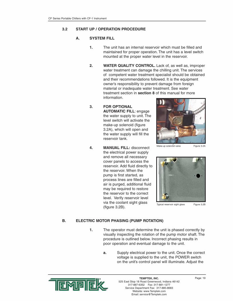
1. The unit has an internal reservoir which must be filled andmaintained for proper operation. The unit has a level switchmounted at the proper water level in the reservoir.
2. WATER QUALITY CONTROL. Lack of, as well as, improperwater treatment can damage the chilling unit. The servicesof competent water treatment specialist should be obtainedand their recommendations followed. It is the equipmentowner’s responsibility to prevent damage from foreignmaterial or inadequate water treatment. See watertreatment section in section 8 of this manual for moreinformation.
3. FOR OPTIONALAUTOMATIC FILL: engagethe water supply to unit. Thelevel switch will activate themake-up solenoid (figure3.2A), which will open andthe water supply will fill thereservoir tank.
4. MANUAL FILL: disconnectthe electrical power supplyand remove all necessarycover panels to access thereservoir. Add fluid directly tothe reservoir. When thepump is first started, asprocess lines are filled andair is purged, additional fluidmay be required to restorethe reservoir to the correctlevel. Verify reservoir levelvia the coolant sight glass(figure 3.2B).
B. ELECTRIC MOTOR PHASING (PUMP ROTATION)
1. The operator must determine the unit is phased correctly byvisually inspecting the rotation of the pump motor shaft. Theprocedure is outlined below. Incorrect phasing results inpoor operation and eventual damage to the unit.
a. Supply electrical power to the unit. Once the correctvoltage is supplied to the unit, the POWER switchon the unit’s control panel will illuminate. Adjust the
Figure 3.2AMake-up solenoid valve
Figure 3.2BTypical reservoir sight glass

CF Series Portable Chillers with CF-1 Instrument
Page: 20TEMPTEK, INC.525 East Stop 18 Road Greenwood, Indiana 46142
317-887-6352 Fax: 317-881-1277Service Department Fax: 317-885-8683
Website: www.Temptek.comEmail: [email protected]
setpoint to 70°F to prevent the compressor fromactivating during this procedure.
b. Remove all necessary cover panels to access thepump motor. Note that the electrical power isengaged at this point and caution must beobserved while the electrical supply is engagedand cabinet panels are removed and opened.
c. Locate the electricmotor (figure 3.2C).The electric motorcan be identifiedwhen the electricalpanel cover is open.The operator mustidentify the motorshaft inside theelectric motorhousing. The motorshaft can be seenthrough the vent slots in the motorhousing or by removing the shaft cover.
d. Toggle theilluminated ON/OFFSWITCH (figure3.2D). This willquickly cycle thepump motor “on”and then “off”.
e. Observe the motorshaft. When theON/OFF SWITCH ison, the motor shaftwill rotate. Whenswitched off, the shaft will slowly “coast” to a stop.As the shaft slows, the operator can identify therotation of the motor shaft. Correct rotation (correctphase) is “clockwise”, when viewed from the rear ofthe motor. Incorrect rotation is “counter-clockwise”(incorrect phase) when viewed from the rear of themotor. If the shaft does not rotate when theON/OFF SWITCH is on, the operator must identifythe cause as outlined in the troubleshooting andrepair section of this manual.
f. If the motor shaft is phased correctly (shaft turns ina clockwise direction), continue with step C. If themotor shaft is NOT phased correctly (shaft turns ina counter-clockwise direction), correct as outlined instep 2.
Figure 3.2CElectric motor
Figure 3.2DOn/Off switch

CF Series Portable Chillers with CF-1 Instrument
Page: 21TEMPTEK, INC.525 East Stop 18 Road Greenwood, Indiana 46142
317-887-6352 Fax: 317-881-1277Service Department Fax: 317-885-8683
Website: www.Temptek.comEmail: [email protected]
2. If the unit is phased incorrectly, the operator must:
a. Disengage the electrical power supply to the unit atthe unit’s disconnect switch. Follow proper lockoutprocedures before proceeding.
b. Once the electrical power supply is disengaged,reverse any two power leads of the power cord atthe disconnect terminals.
c. Note: reversing any two power leads of the powercord will correctly phase the power supply to theunit. The operator must reverse the power leadsat the disconnect switch only and not at thepower entry terminals on the unit’s electricalpanel. The unit’s internal electrical system wiring isphased correctly at the factory and must not bealtered in the field.
C. PROCESS FLOW ADJUSTMENTS
1. The operator must determine and set proper water flow ratefor the most efficient and trouble free operation.
a. Water flow rate through the process is determinedby the pressure losses in the process loop.Generally, higher flow rates result in turbulent flowachieving maximum temperature control and lowermaintenance. Since the evaporator in most liquidchillers is flow sensitive, the efficiency of operationis directly related to the flow of liquid.
b. Maximum chiller efficiency is obtained atapproximately 2.4 gpm per ton of rated capacity.Low liquid flow can reduce efficiency and in somecases allow ice to develop in the evaporator whichcan damage the evaporator. Excessive liquid flowwill trip the motor overload protection circuit.
2. Switch on the illuminated ON/OFF SWITCH to activate theprocess pump. Wait a few moments to allow air to be purgefrom system. Observe the COOLANT pressure gauge forsteady readout. Two items the operator for look for are lowflow or excessive flow conditions.
3. LOW FLOW: If a low flow condition is present, be sure allprocess valves are open. If all process valves are open anda low flow conditions exists, consider the following:
a. To operate under a low flow condition, it isnecessary to install a flow bypass system in theprocess circuitry. This will allow a portion of the flow

CF Series Portable Chillers with CF-1 Instrument
Page: 22TEMPTEK, INC.525 East Stop 18 Road Greenwood, Indiana 46142
317-887-6352 Fax: 317-881-1277Service Department Fax: 317-885-8683
Website: www.Temptek.comEmail: [email protected]
to bypass the process and return directly to thechiller. This keeps the total flow above the cutoffpoint. Figure 3.2E illustrates a typical bypass loop.
b. Some models may have a factory installed bypass.Adjust the valve accordingly.
4. EXCESSIVE FLOW: if the flow rate exceeds the motor HPcapacity, the electric motor will draw excessive amps. This isa result of the process loop’s ability to flow water at agreater rate than can be provided by the pump. Thiseventually results in tripping the thermal motor overloadrelay (overload relays open) and the unit will shut down.
a. If an excessive flowsituation isencountered and themotor overloadcircuit has tripped,the operator mustmanually reset theoverload relay(figure 3.2F) beforeoperations cancontinue.
b. This is done byopening the electrical panel cover, identifying thereset lever on the overload relay, and pushing thereset lever “in” until the overloads are reset(evidenced by a “clicking” sound as the overloadsreset).
5. Set the process flow rate by measuring the pump motoramperage and adjusting the process flow rate via the motoramperage:
a. Open electrical cabinet panel door. Note that theelectrical power is engaged at this point andcaution must be observed while the cabinetpanel is open.
Figure 3.2E Typical low flow by-pass loop
Figure 3.2FReset level on overload relay

CF Series Portable Chillers with CF-1 Instrument
Page: 23TEMPTEK, INC.525 East Stop 18 Road Greenwood, Indiana 46142
317-887-6352 Fax: 317-881-1277Service Department Fax: 317-885-8683
Website: www.Temptek.comEmail: [email protected]
b. Identify the motor starter block. This block consistsof the motor starter contactor and the overloadrelay.
c. Place an amp meter on a single power leademanating from the overload relay.
d. Identify the electricpump motor. Locatethe name plate onthe motor housing(figure 3.2G). Thefull load amp ratingfor the motor islisted on the nameplate.
e. Engage theelectrical powersupply and start thepump motor by pressing on the illuminated ON/OFFswitch on the display.
f. The amp meter will display the motor amps.Compare the actual motor amps as displayed onthe amp meter to the full load amp rating as listedon the motor name plate.
g. If the amp draw is excessive (higher than the listedname plate amp rating), a throttling valve must beinstalled in the “from process” circuit line. Thepreferred throttling valve is a manual activated ballvalve. If necessary, follow proper shut down anddisconnect procedures to install a throttling valve.
h. With the throttling valve installed, fully close thevalve and then engage the pump. Slowly open thethrottling valve and monitor the motor amps asdisplayed on the amp meter until the actual motoramps equals the listed full load amp rating of themotor. The process flow is now correctly adjusted.
Figure 3.2GMotor Data Plate

CF Series Portable Chillers with CF-1 Instrument
Page: 24TEMPTEK, INC.525 East Stop 18 Road Greenwood, Indiana 46142
317-887-6352 Fax: 317-881-1277Service Department Fax: 317-885-8683
Website: www.Temptek.comEmail: [email protected]
3.3 INSTRUMENT/OPERATION
A. INSTRUMENT START-UP
1. When the correct electrical power and adequate watersupply pressure are supplied to the unit, it is possible tostart the unit.
2. Upon power up, the instrument displays “ChF” indicatingthat the unit is in Fahrenheit temperature mode or “ChC”indicating that it is in Celsius mode. The control then showsthe current setpoint for approximately 2 seconds beforereverting to the To Process temperature. When power issupplied to the unit, the ON/OFF switch will illuminate.
3. Precautions:
The chiller control is programmed from the factory with asetpoint range of 48° to 90°F. To operate below 48°F, theaddition of inhibited propylene glycol and modification of thesafety control settings are required. Diligent monitoring ofthe water/glycol solution is mandatory to prevent freezing ofthe evaporator. Freezing may cause the evaporator torupture allowing water and freon to mix which will causemajor damage to the refrigeration system.
On R22, R134A and R407C models operating above 70°Fand R404A models operating above 60°F requires theaddition of a refrigerant crankcase pressure regulating(CPR) valve. The CPR valve is necessary to preventoverloading of the compressor which can cause prematurefailure. R410A models may be operated up to 80°F withouta CPR valve.
Figure 3.3AInstrument display

CF Series Portable Chillers with CF-1 Instrument
Page: 25TEMPTEK, INC.525 East Stop 18 Road Greenwood, Indiana 46142
317-887-6352 Fax: 317-881-1277Service Department Fax: 317-885-8683
Website: www.Temptek.comEmail: [email protected]
Contact your local refrigeration contractor or the factory forfurther information. The operating range of the chiller controlmay be changed to 10°F - 90°F by adjusting the SetpointLockout (SPL) jumper. Refer to the technical section of thismanual for more information.
4. After selecting a set point temperature, the operator mayleave the display in the SET POINT state. The display willautomatically return to the TO PROCESS temperature stateafter thirty seconds. If the operator leaves the display in anystate other than the TO PROCESS state, the display willautomatically revert after 30 seconds of inactivity.
B. INSTRUMENT OPERATION
1. To start the unit, toggle on the illuminated ON/OFFSWITCH. The chiller control will begin temperature controloperations.
2. To select setpoint temperature, press and hold the UPARROW or DOWN ARROW keys until the desired set pointtemperature is displayed in the TEMPERATURE WINDOW.The default range for the setpoint temperature is 48° - 90°For 9° - 32°C.
3. The setpoint temperature can be displayed by pressing theUP ARROW or DOWN ARROW keys. The setpointtemperature will be displayed for 5 seconds.
4. When the compressor is turned off, the instrument will wait3 minutes before turning it back on regardless of the ToProcess temperature or setpoint. If a fault has occurred, thecontrol will attempt to turn the compressor on after 3minutes powered down. If the fault condition remains, thecontrol will turn the compressor off and retry after 1 minute.This sequence will repeat until the compressor turns on orinstrument power is cycled.
5. Under normal conditions (no fault conditions, compressorhas been off for three minutes) the instrument will turn onthe compressor when the To Process temperature is abovethe setpoint.The instrument will turn on the hot gas bypass when the ToProcess temperature is below the setpoint by no more than3 degrees.
The instrument will turn off the compressor and hot gasbypass when the To Process temperature is 4 degrees ormore below the setpoint.

CF Series Portable Chillers with CF-1 Instrument
Page: 26TEMPTEK, INC.525 East Stop 18 Road Greenwood, Indiana 46142
317-887-6352 Fax: 317-881-1277Service Department Fax: 317-885-8683
Website: www.Temptek.comEmail: [email protected]
C. INSTRUMENT CONTROLS
1. ILLUMINATED ON/OFF SWITCH: this rocker switch startsor stops the unit. Electrical power is supplied to the unitwhen the switch is illuminated.
2. UP ARROW and DOWN ARROW KEYS: depress and holdthis push button to increase (UP ARROW) or decrease(DOWN ARROW) the setpoint temperature. If the pushbutton is pressed momentarily the setpoint value isincremented or decremented by one degree. If the pushbutton is held down the setpoint will increase or decreasecontinously.
3. SETPOINT LOCK OUT JUMPER: this jumper controlswhether the user is allowed to reduce the setpoint below48°F or 9°C. If the jumper is in position 1 (farthest from theSPL label) the user IS NOT ALLOWED to reduce thesetpoint below 48°F or 9°C. If the jumper is in position 2(closest to the SPL label) the user is allowed to reduce thesetpoint to 10°F or -11°C.
4. TEMPERATURE DISPLAY JUMPER: if this jumper is in the“F” position, the To Process and Setpoint temperatures aredisplayed in Fahrenheit. If the jumper is in the “C” position,the To Process and Setpoint temperatures are displayed inCelsius.
5. Probe Calibration: this pot (CALPOT 1) is used to calibratethe probe circuit.
D. STATUS LIGHTS
1. COMPRESSOR: illuminates when compressor is turned on.
2. CAPACITY CONTROL: illuminates when capacity controlsystem is turned on.
3. REFRIGERANT FAULT: illuminates when there is a high
Setpoint Lock Out Jumper Temperature Display Jumper Probe Calibration
Figure 3.3B

CF Series Portable Chillers with CF-1 Instrument
Page: 27TEMPTEK, INC.525 East Stop 18 Road Greenwood, Indiana 46142
317-887-6352 Fax: 317-881-1277Service Department Fax: 317-885-8683
Website: www.Temptek.comEmail: [email protected]
pressure or low pressure alarm. Check troubleshootingsection of this manual for more details.
High Pressure Alarm. If the chiller control detects a highpressure condition it will immediately turn off thecompressor and hot gas bypass.
Low Pressure Alarm. Afterthe compressor is turned on,the control has a 15 secondbuffer for the low pressurealarm. If a low pressurecondition occurs within thefirst 15 seconds, the controlwaits the amount of timespecified by the “LP TIME”potentiometer beforeindicating an alarm andturning off the compressor. Ifthe condition is correctedbefore the time expires, no alarm occurs. If a low pressurecondition occurs 15 seconds after the compressor turns on,the instrument waits 20 seconds before indicating an alarmand turning off the compressor.
E. TEMPERATURE DISPLAY
1. A three digit display window indicates the appropriatetemperature. The window also displays the numeric valuefor the setpoint temperature.
2. The To Process temperature is always displayed unless abutton has been pressed. If there is a probe error, thedisplay will show three dashes “---”.
F. PRESSURE GAUGES
1. PROCESS PRESSURE GAUGE: indicates process pumppressure.
2. REFRIGERANT HEAD PRESSURE GAUGE: indicatesrefrigerant pressure on the discharge side of thecompressor. The refrigerant head pressure is also thecondensing pressure which is critical to equipmentefficiency. Head pressure on water condensed units willvary with ambient temperatures between 190-290 psig.
3. LOW PRESSURE GAUGE: indicates refrigerant pressureon the suction side of the compressor. This pressure willfluctuate with the process temperature.
Figure 3.3CLow Pressure Potentiometer.

CF Series Portable Chillers with CF-1 Instrument
TEMPTEK, INC.525 East Stop 18 Road Greenwood, Indiana 46142
317-887-6352 Fax: 317-881-1277Service Department Fax: 317-885-8683
Website: www.Temptek.comEmail: [email protected]
Page: 28
3.4 SHUT DOWN/DISCONNECT SEQUENCE
A. PRECAUTIONS/WARNINGS
1. The operator must precisely follow all shut down proceduresoutlined in this manual. If the operator fails to followprecisely all procedures outlined in this manual, an unsafecondition can develop resulting in damage to the unit orpersonal injury.
B. UNIT SHUT DOWN
1. To shut down the unit without disconnecting from theprocess:
a. Move the ON / OFF switch to the off position.
b. Maintain electrical power to the unit at all timesexcept for service purposes.
2. To shut down the unit and disconnect from theprocess:
a. Move the ON / OFF switch to the off position.
b. Disengage the electrical supply to the chiller at thedisconnecting device.
c. Disconnect all process lines.

CF Series Portable Chillers with CF-1 Instrument
Page: 29TEMPTEK, INC.525 East Stop 18 Road Greenwood, Indiana 46142
317-887-6352 Fax: 317-881-1277Service Department Fax: 317-885-8683
Website: www.Temptek.comEmail: [email protected]
4.0 TROUBLESHOOTING4.1 SENSOR4.2 PROCESS PUMP 4.3 COMPRESSOR 4.4 LOW FLOW4.5 BLOWER/FAN4.6 HIGH PRESSURE4.7 LOW PRESSURE4.8 WATER LEVEL4.9 FREEZESTAT 4.10 CRANKCASE HEATER 4.11 CHILLER CONTROLLER

CF Series Portable Chillers with CF-1 Instrument
Page: 30TEMPTEK, INC.525 East Stop 18 Road Greenwood, Indiana 46142
317-887-6352 Fax: 317-881-1277Service Department Fax: 317-885-8683
Website: www.Temptek.comEmail: [email protected]
4.1 UNIT WILL NOT START
A. Power off. Check main disconnect.
B. Main line open. Check fuses.
C. Loose terminals. Tighten terminals with POWER OFF.
D. Control circuit open. check control voltage fuses and transformer.
4.2 COMPRESSOR HUMS BUT WILL NOT START
A. Contactor. Check contacts and contactor operation.
B. Low voltage. Check voltage at main and at the unit. If voltage is OKat the main but low at the unit, increase wire size. If low at main,consult your local power company. Voltage must be +/- 10%nameplate rating.
C. No power on one phase of a three phase unit. Check fuses incontrol panel and main disconnect. Also check unit wiring, mainplant fuse and wiring. If the problem is with the main power supplycoming into the plant, call the local power company.
D. Loose terminals. Tighten terminals with POWER OFF.
4.3 SHUTS OFF ON HIGH PRESSURE CONTROL
Note. Refrigerant high pressure will vary with ambient temperature.The high pressure switch manually reset when discharge pressurefalls to a safe level. The switch is located inside the electrical panel.
A. Air-cooled units:
1. Insufficient condenser air flow. Check condenser filter fordirt, fins may be plugged with dirt or foreign material. Also,check for proper fan rotation.
2. Fan motor not operating. Have electrician check fusesand wiring, motor starter and overloads, and motor. Repairor replace motor if defective.
B. Water-cooled units:
1. Water regulator valve. Adjust condenser water regulatorvalve to maintain 100°F to 105°F refrigerant condensingtemperature*. If valve is defective, have valve repaired orreplaced by a refrigeration serviceman.
* See Temperature-Pressurechart in Section 8.5 forrefrigerant pressure.

CF Series Portable Chillers with CF-1 Instrument
Page: 31TEMPTEK, INC.525 East Stop 18 Road Greenwood, Indiana 46142
317-887-6352 Fax: 317-881-1277Service Department Fax: 317-885-8683
Website: www.Temptek.comEmail: [email protected]
2. Insufficient condenser water flow. Check condenserwater pumping system.
3. Condenser water temperature too high. Check coolingtower or proper operation city water temperature.
4. Condenser water tubes scaled. Clean with brushes andchemicals approved by the Advantage Service Department.
C. Excess refrigerant. have refrigeration serviceman purge systemwhile operating until bubbles first appear in sight glass. The havethe unit recharged until sight glass clears.
D. Air in system. Have refrigeration serviceman purge the system.
E. Improperly set high pressure control. Have refrigerationserviceman reset or replace the control if defective.
4.4 SHUTS OFF ON LOW PRESSURE CONTROL
Note: The low pressure switch will automatically resets when the pressurerises above the cut-in pressure. If this does not occur contact theservice department for instructions.
The low pressure switch is set to cut-out at 32°F and cut-in at36°F - 39°F*. If a low pressure condition exists for more than fiveseconds the compressor will stop and a “L-P” fault will appear inthe display window.
After the refrigerant pressure rises above the cut-in pressure, athree minute time delay will occur before the compressor restarts.This will protect the evaporator and compressor from damageshould a problem occur in the refrigeration system or if the chiller isoperated under circumstances which could cause damage to therefrigeration system.
A. Air-cooled units:
Head pressure too low. Check that entering airtemperature is above 60°F. If below 60°F, find out reasonwhy.
B. Water-cooled units:
Head pressure too low. Adjust condenser water regulatingvalve to maintain 100°F - 105°F refrigerant condensingtemperature*. Have refrigeration serviceman repair valveor replace if defective.
* See Temperature-Pressurechart in Section 8.5 forrefrigerant pressure.
* See Temperature-Pressurechart in Section 8.5 forrefrigerant pressure.

CF Series Portable Chillers with CF-1 Instrument
Page: 32TEMPTEK, INC.525 East Stop 18 Road Greenwood, Indiana 46142
317-887-6352 Fax: 317-881-1277Service Department Fax: 317-885-8683
Website: www.Temptek.comEmail: [email protected]
C. Low refrigerant charge. Check for adequate refrigerant charge(bubbles or misty sight glass indicates low charge). If charge is low,have system checked for leaks and recharged by a refrigerationserviceman.
D. Improperly set low pressure switch. Have a refrigerationserviceman reset control or replace if defective.
E. Restriction in the liquid line.
1. Clogged filter drier. Check for pressure ortemperature drop and have drier core replaced by arefrigeration serviceman.
2. Liquid line valve or suction valve oncompressor is partially closed. Open fully.
3. Liquid line solenoid not opening fully or leakingduring off cycle. have repaired or replaced ifdefective by a refrigeration serviceman.
4. Expansion valve plugged or inoperative. Checkthermal bulb and capillary tube for damage. Haverepaired or replaced if defective by a refrigerationserviceman.
4.5 COMPRESSOR SHUTS OFF ON INTERNAL OVERLOAD
A. Control does not reset. Have compressor windings and internalsolid state safety control checked by a refrigeration serviceman.Have it repaired or replace if defective.
4.6 UNITS SHUTS OFF ON FREEZESTAT CONTROL (OPTIONAL)
A. Low water flow. check valves to ensure they are opened. Check ifpump is operating. Check and clean filter in the chilled water circuit.
B. Evaporator plugged. Call a refrigeration serviceman to inspect thevessel for foreign material in the evaporator inlet or scaling on thetubes.
C. Improperly set freezestat control. Have a refrigeration servicemanreset the control or replace if defective.
4.7 LOW OR NO PROCESS PRESSURE OR WATER FLOW
A. Valves. Check if water valves are open.

CF Series Portable Chillers with CF-1 Instrument
Page: 33TEMPTEK, INC.525 East Stop 18 Road Greenwood, Indiana 46142
317-887-6352 Fax: 317-881-1277Service Department Fax: 317-885-8683
Website: www.Temptek.comEmail: [email protected]
B. Pump. Check pump for correct rotation. Check pump suction forrestriction. Replace motor if defective.
C. Filters. Check filter in the chilled water circuit and clean ifnecessary.
D. Pressure switch (or flow switch). Readjust or replace if defective.
E. Fuses and wiring. Have electrician check the fuses and wiring.
4.8 COOLING CAPACITY INADEQUATE
A. Low refrigerant charge. Check for adequate refrigerant charge(bubbles or misty sight glass indicates low charge). If charge is low,have system checked for leaks and recharged by a refrigerationserviceman.
B. Hot-gas bypass valve stuck open. Have repaired or replace ifdefective by a refrigeration serviceman.
C. Expansion valve plugged or inoperative. Check thermal bulb andcapillary tube for damage. Have repaired or replaced if defective bya refrigeration serviceman.
D. Plugged filter. Check filter in chilled water circuit and clean.
E. Air in system. Purge air.
4.9 SENSOR
The sensor is a solid state temperature transducer which convertstemperature input to proportional current output. To quickly test for adefective probe, switch connections between the defective probeand a probe known to be working properly. A defective sensor willdisplay a “---” in the display window on the instrument control.
4.10 PUMPS
A. The centrifugal pump is designed to operate at a specific flow andpressure at the maximum run load amp draw of the motor. Toomuch flow can overload the motor and cause the overload circuit toopen and stop the pump.
B. If the overload trips, check for electrical shorts, loose wires, orblown fuses. If these check OK, reset the overload circuit andrestart the chiller.
C. Check the amp draw and if overloaded, partially close the fromprocess line valve until the amp draw drops to the proper level.

CF Series Portable Chillers with CF-1 Instrument
Page: 34TEMPTEK, INC.525 East Stop 18 Road Greenwood, Indiana 46142
317-887-6352 Fax: 317-881-1277Service Department Fax: 317-885-8683
Website: www.Temptek.comEmail: [email protected]
4.11 CRANKCASE HEATER (OPTIONAL)
A. If the crankcase heater is not drawing current during thecompressor off cycle, check for a defective crankcase heater,defective fuses or defective interlock on the compressor starter.
4.12 CHILLER CONTROLLER
A. The display is used for all normal set ups, diagnostics, temperaturereadout, and operational information. Note: the display is not fieldrepairable. It can be easily removed and replaced if required.
B. The CPU is mounted inside the electrical enclosure, this containsthe software and various electronic components which make theinstrument work. Note: the CPU is not a field repairable part. It canbe easily removed and replaced if a problem arises. Do not attemptto open the enclosure box as this will void the warranty. The threephase module interprets the incoming power supply and sends theinformation to the CPU. Note: the 3 phase module is not fieldrepairable. It can be easily removed and replaced if required.

CF Series Portable Chillers with CF-1 Instrument
Page: 35TEMPTEK, INC.525 East Stop 18 Road Greenwood, Indiana 46142
317-887-6352 Fax: 317-881-1277Service Department Fax: 317-885-8683
Website: www.Temptek.comEmail: [email protected]
5.0 MAINTENANCE5.1 WARRANTY SERVICE PROCEDURE5.2 PERIODIC PREVENTATIVE MAINTENANCE5.3 SPECIAL MAINTENANCE5.4 SOLENOID VALVE SERVICE5.5 PUMP SEAL SERVICE5.6 CHECKING THE REFRIGERANT CHARGE5.7 PROPER CLEANING PROCEDURE FOR BRAZED PLATE EVAPORATOR

CF Series Portable Chillers with CF-1 Instrument
Page: 36TEMPTEK, INC.525 East Stop 18 Road Greenwood, Indiana 46142
317-887-6352 Fax: 317-881-1277Service Department Fax: 317-885-8683
Website: www.Temptek.comEmail: [email protected]
5.1 WARRANTY SERVICE PROCEDURE
A. In the event of a problem with a chiller that can not be resolved bynormal troubleshooting procedures, the customer is invited toconsult the Service department for assistance. The correct modelnumber and serial number of the chiller must be available. Theservice department will attempt to isolate the problem and adviserepair procedures. Often times, with the customer’s input and withthe machine diagnostics, problems can be determined with “over-the-phone” consultation.
B. If the problem is beyond the scope of “over-the-phone” consultation,and if the warranty status of the machine is valid, the Servicedepartment will contact the nearest authorized service contractorand provide authorization to conduct an “on-site” inspection of theunit in order to determine the course of repair. If the chiller is notcovered by the warranty, the Service department will advise on therepair and recommend available service contractors.
C. Temptek manufactures a complete line of heat transfer equipment. Itis of the utmost importance that the Service department have thecorrect model number and serial number of the machine inquestion. This will allow the Service department to obtain the correctmanufacturing records which will help the service department toproperly troubleshoot the problem and obtain the properreplacement parts when they are required. This information isstamped on the metal data tag that is attached to the electricalenclosure of each machine.
D. The Service department must be notified prior to any repair orservice of a warranty nature. Warranty claims will not be honoredwithout prior authorization.
5.2 PERIODIC PREVENTATIVE MAINTENANCE
A. Lubricate all motors. Note that some motors are supplied withsealed bearings.
B. Tighten all wire terminals.
C. Clean and check motor starter and contactor contacts.
D. Check safety switch settings.
E. Clean condenser fins of dust and dirt (air cooled models only).
F. Back flush evaporator.
G. Check glycol/water solution ratio for operating temperature.
H. Check system for leaks.

CF Series Portable Chillers with CF-1 Instrument
Page: 37TEMPTEK, INC.525 East Stop 18 Road Greenwood, Indiana 46142
317-887-6352 Fax: 317-881-1277Service Department Fax: 317-885-8683
Website: www.Temptek.comEmail: [email protected]
I. Refrigerant sight glass: check for bubbles when compressor isoperating at 100%. Check the moisture indicator for a color otherthan green.
J. Clean unit.
5.3 SPECIAL MAINTENANCE
A. Any service of the refrigeration system must be accomplished by acertified refrigeration technician.
1. Vacuum check compressor.
2. Addition of compressor oil.
3. Addition of refrigerant.
4. Repair of a refrigerant leak.
5. Adjustment of super heat.
6. Changing of filter-drier or drier core.
7. Repair of a refrigeration solenoid.
8. Valve plate replacement on compressor.

CF Series Portable Chillers with CF-1 Instrument
Page: 38TEMPTEK, INC.525 East Stop 18 Road Greenwood, Indiana 46142
317-887-6352 Fax: 317-881-1277Service Department Fax: 317-885-8683
Website: www.Temptek.comEmail: [email protected]
5.4 SOLENOID VALVE SERVICE
A. Units with the water make-upsystem use a solenoid valve (figure5.4A) to regulate flow into thereservoir tank. The solenoid valve iscontrolled by the float switch.
B. Generally, solenoid valves fail dueto poor water quality, low waterflow, or defective valve elements.
C. The operator should follow thisprocedure to service the make-upsolenoid valve:
1. Disengage process operations according to the procedureoutlined in section 3.4. The operator must be certainprocess fluid temperature is under 100°F and pressure isrelieved (pressure gauge reads “0”) and water system flowis shut off and all pressure relieved.
2. Disengage main power supply. The operator must verify thePOWER light on the Maximum display is “off”.
3. Remove or open any access cover panel and set aside togain access to the cooling solenoid valve.
4. The operator must be certain all water system pressure isrelieved. Use the pressure relief valve mounted in the drainmanifold to relieve all pressure.
5. Identify the retaining screw(figure 5.4B) on thesolenoid valve coil. Removethe screw. Keeping allelectrical connectionsintact, lift the coil off of theenclosure tube and setaside.
6. Use a pair of channel lockpliers or a pipe wrench toseparate the bonnetassembly from the valve body.The plunger is “loose” inside the enclosing tube. Be certainit is retained in the enclosure tube as the bonnet is removed(figure 5.4C).
7. Identify the diaphragm assembly. Gently remove theassembly from the valve body (figure 5.4D).
Coil Figure 5.4B
Retaining screw
Typical water make-upsolenoid valve
Figure 5.4A

CF Series Portable Chillers with CF-1 Instrument
Page: 39TEMPTEK, INC.525 East Stop 18 Road Greenwood, Indiana 46142
317-887-6352 Fax: 317-881-1277Service Department Fax: 317-885-8683
Website: www.Temptek.comEmail: [email protected]
8. Identify the mesh screen.Gently removed the meshscreen and clean orreplace as necessary.
9. Clean the valve body.
10. Reset the mesh screen intothe valve body.
11. If a new diaphragmassembly was obtained,continue with step 12. Ifnot, disassemble thediaphragm assembly andnote component order(figure 5.4E). Clean thevalve port, plate, collar andO-ring. Once cleaned,reassemble the diaphragm.
12. Set the reassembleddiaphragm assembly or thenew assembly back into thevalve body. The stemshould be facing out of thevalve body.
13. Inset the plunger withspring first into theenclosing tube of the topbonnet (figure 5.4F).Holding the plunger in theenclosure tube, set the topbonnet onto the valve bodyand tighten.
14. Place the coil onto the topbonnet and replace theretaining screw.
15. Open the water supply anddrain valves (if installed) tocirculate water through thesupply and drain manifolds.Check the solenoid valvefor leakage. Restart the unitas outlined in section 3.
Figure 5.4FPlungerSpring
Top bonnet Enclosure tube
Top bonnet Figure 5.4CEnclosure tube
Plunger Diaphragm assembly
Figure 5.4DO-Ring
Diaphragm assembly Mesh screen
Figure 5.4EO-RingDiaphragm and stem
Collar Plate
CF Series Portable Chillers with CF-1 Instrument
Page: 40TEMPTEK, INC.525 East Stop 18 Road Greenwood, Indiana 46142
317-887-6352 Fax: 317-881-1277Service Department Fax: 317-885-8683
Website: www.Temptek.comEmail: [email protected]
5.5 PUMP SEAL SERVICE
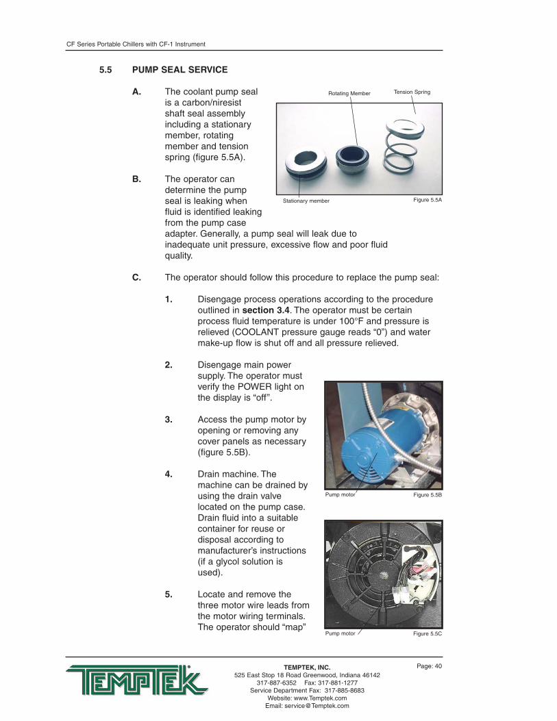
A. The coolant pump sealis a carbon/niresistshaft seal assemblyincluding a stationarymember, rotatingmember and tensionspring (figure 5.5A).
B. The operator candetermine the pumpseal is leaking whenfluid is identified leakingfrom the pump caseadapter. Generally, a pump seal will leak due toinadequate unit pressure, excessive flow and poor fluidquality.
C. The operator should follow this procedure to replace the pump seal:
1. Disengage process operations according to the procedureoutlined in section 3.4. The operator must be certainprocess fluid temperature is under 100°F and pressure isrelieved (COOLANT pressure gauge reads “0”) and watermake-up flow is shut off and all pressure relieved.
2. Disengage main powersupply. The operator mustverify the POWER light onthe display is “off”.
3. Access the pump motor byopening or removing anycover panels as necessary(figure 5.5B).
4. Drain machine. Themachine can be drained byusing the drain valvelocated on the pump case.Drain fluid into a suitablecontainer for reuse ordisposal according tomanufacturer’s instructions(if a glycol solution isused).
5. Locate and remove thethree motor wire leads fromthe motor wiring terminals.The operator should “map”
Stationary member
Rotating Member Tension Spring
Figure 5.5A
Pump motor Figure 5.5B
Pump motor Figure 5.5C

CF Series Portable Chillers with CF-1 Instrument
Page: 41TEMPTEK, INC.525 East Stop 18 Road Greenwood, Indiana 46142
317-887-6352 Fax: 317-881-1277Service Department Fax: 317-885-8683
Website: www.Temptek.comEmail: [email protected]
the wire terminal locationsto ensure correct rewiring.The power cord should beremoved from the motorhousing (figure 5.5C).
6. Locate and remove thepump casing bolts. Thesebolts secure the motor andmotor adapter to the pumpcasing (figure 5.5D).
7. Separate the motor andmotor adapter from thepump casing to expose thepump impeller (figure5.5E). Remove the motorand motor adapter from theunit and place on aworkbench to continue theprocedure.
8. Locate and remove thedust cap from motor end toexpose slotted motor shaft.The motor shaft is free torotate, but must be securedto remove the impeller. Tosecure the motor shaft,insert a flat bladed screwdriver in slot to hold theshaft stationary (Figure5.5F).
9. Locate and remove impellerlocking screw (Figure5.5G). Using a socket andratchet, the impellerretaining screw can beremoved. Once theretaining screw is removed,the impeller can be“unthreaded” from themotor shaft to expose thepump seal assembly.
10. Remove all seal parts(Figure 5.5H). Note sealcomponent arrangement tofacilitate reassembly.
Typical pump casing bolt Figure 5.5D
Motor shaft Figure 5.5F
Typical impeller Figure 5.5G
Impeller Figure 5.5E

CF Series Portable Chillers with CF-1 Instrument
Page: 42TEMPTEK, INC.525 East Stop 18 Road Greenwood, Indiana 46142
317-887-6352 Fax: 317-881-1277Service Department Fax: 317-885-8683
Website: www.Temptek.comEmail: [email protected]
11. Clean motor shaft andlubricate with a mild soapsolution.
12. Install new stationary sealmember in pump casingcavity (figure 5.5I). Theoperator must be certainthe stationary seal memberis fully squared and seatedin cavity.
13. Slide the rotating memberonto lubricated pump shaft(figure 5.5J). The operatormust be certain not todamage or tear rubberbellows assembly.
14. Place the spring onto therotating member.
15. Align the impeller, springand rotating member beforereinstalling the impeller(figure 5.5K). The operatormust be certain the springand rotating member arealigned before the impelleris fully tighten and theimpeller retaining screw isreinstalled.
16. Clean pump casing,cavities, impeller and O-ring before reassembly.
17. Mate the motor and motoradapter to the pumpcasing. Reinstall the pumpcasing bolts.
18. Reconnect the motor powercord and leads.
19. Restore all cover panels aswere removed.
E. When the pump seal replacementprocedure is complete, the operatormay restart the unit according thesection 3.
Stationary member Figure 5.5I
Stationary member Figure 5.5J
Seal members Figure 5.5K
Seal components Figure 5.5H

CF Series Portable Chillers with CF-1 Instrument
Page: 43TEMPTEK, INC.525 East Stop 18 Road Greenwood, Indiana 46142
317-887-6352 Fax: 317-881-1277Service Department Fax: 317-885-8683
Website: www.Temptek.comEmail: [email protected]
5.6 CHECKING THE REFRIGERANT CHARGE
A. All standard chillers aremanufactured with thermostaticexpansion valves as the meteringdevice to the evaporator.
B. Al chillers have a refrigerant sightglass (figure 5.6A) with a moistureindicator. To check the refrigerantcharge under normal operatingconditions:
1. Remove the plastic capcovering the sight glass.
2. Start the chiller and allow system pressures andtemperatures to stabilize.
3. With the unit operating at 100% capacity (not in the“capacity control” mode) the sight glass should appear clearwith no foam or bubbles evident. If foam or bubbles areevident, the chiller has suffered from a loss of refrigerantand should be checked by a qualified refrigerationtechnician.
4. The “dot” in the middle of the sight glass is the moistureindicator. It should appear green at all times. A white oryellow color indicates moisture has invaded the refrigerationsystem, which is detrimental to the life of the compressor.The filter-drier should be replaced by a qualifiedrefrigeration technician.
Sight Glass Figure 5.6A

CF Series Portable Chillers with CF-1 Instrument
Page: 44TEMPTEK, INC.525 East Stop 18 Road Greenwood, Indiana 46142
317-887-6352 Fax: 317-881-1277Service Department Fax: 317-885-8683
Website: www.Temptek.comEmail: [email protected]
5.7 PROPER CLEANING PROCEDURE FOR BRAZED PLATE EVAPORATORS
A. The brazed plate evaporator ismade of stamped stainless steelplates, furnace brazed together withcopper based joints. The complexgeometry of the flow passagespromotes turbulent flow which giveshigh efficiency and reduces foulingby mineral deposits. Large solidssuch as plastic pellets or chunks ofmineral deposits will collect at thewater inlet port at the evaporatorand restrict flow through some ofthe passages. If this possibilityexists, the manufacturer recommends filters or strainers be added tothe “from process” line. If the evaporator becomes fouled there are acouple of methods for cleaning.
B. To begin, remove the piping to the “water in” port at the evaporator.Remove any solids that have collected at this point. Then back flushthe evaporator to remove any solids that may be trapped betweenthe plates (see back flush procedure below). If there are mineraldeposits adhered to the plates, the evaporator must be back flushedwith a mild acid solution (5% phosphoric or 5% oxalic acid isrecommended.) After cleaning rinse with clear water beforereturning to service. Continue with step C on the next page.
C. Back flushing procedure:
1. Turn off all power to the machine. For chillers with areservoir tank, drain the tank to below the evaporator outlet.For chillers without a reservoir tank, drain total unit.
2. Connect a water supply hose to the evaporator water outlet.If acid cleaning, connect the discharge hose from the acidpump to the evaporator outlet port.
3. Connect a hose to the evaporator water supply port and toan appropriate containment vessel. If acid cleaning, connectthe evaporator water inlet port to an acid solution reservoirtank. Dispose of all back flush fluid according to localcodes.
4. The cleaning fluid source should have at least 20 psiavailable. If acid cleaning, follow the instructions suppliedwith the acid solution carefully.
5. When the procedure is complete, reinstall all water lines tooriginal factory orientation. Restart the unit and check forproper operation.
Evaporator Figure 5.6A

CF Series Portable Chillers with CF-1 Instrument
Page: 45TEMPTEK, INC.525 East Stop 18 Road Greenwood, Indiana 46142
317-887-6352 Fax: 317-881-1277Service Department Fax: 317-885-8683
Website: www.Temptek.comEmail: [email protected]
BRAZED PLATE HEAT EXCHANGER(EVAPORATOR)
FREON OUT
FREON IN
ORIGINAL WATER OUT PORTBACKFLUSH WATER IN PORT(SUPPLY BACKFLUSHING WATER
FLOW TO THIS PORT)
ORIGINAL WATER IN PORTBACKFLUSH WATER OUT PORT
(ROUTE WATER TO PROPERSEWER OR DRAIN CONTAINER)
6. Note: this procedure is not normal maintenance.Maintaining proper water quality and filtration will minimizethe need to back flush the evaporator.

Page: 46
THIS PAGE INTENTIONALLY BLANK

CF Series Portable Chillers with CF-1 Instrument
Page: 47TEMPTEK, INC.525 East Stop 18 Road Greenwood, Indiana 46142
317-887-6352 Fax: 317-881-1277Service Department Fax: 317-885-8683
Website: www.Temptek.comEmail: [email protected]
6.0 COMPONENTS6.1 WATER SYSTEM6.2 REFRIGERATION SYSTEM

CF Series Portable Chillers with CF-1 Instrument
Page: 48TEMPTEK, INC.525 East Stop 18 Road Greenwood, Indiana 46142
317-887-6352 Fax: 317-881-1277Service Department Fax: 317-885-8683
Website: www.Temptek.comEmail: [email protected]
6.1 WATER SYSTEM
A. MOTOR/PUMP ASSEMBLY: themotor/pump assembly circulateschilled fluid to the process loop. Thepump assembly is built of totalstainless steel to maintain waterquality (figure 6.1A).
B. FREEZESTAT: the freezestat aidsin protecting the evaporator frompotential freezing. The freezestat isfactory adjusted to 40°F. Thefreezestat must be field adjusted foroperating with setpoints below 48°F(figure 6.1B).
6.2 REFRIGERATION SYSTEM
A. COMPRESSOR: compressors takelow pressure/low temperaturerefrigerant gas and compress thegas into high pressure/hightemperature gas (figure 6.2A).
B. AIR COOLED CONDENSER: theair cooled condenser removesBTU’s from the compressedrefrigerant gas. The action causesthe gas to “condense” into a liquidstate still under high pressure. Airflow across the condenser isachieved via a motor driven fanassembly or centrifugal blower(figure 6.2B).
C. WATER COOLED CONDENSER:the water cooled condenserremoves BTU’s (heat) from thecompressed refrigerant gas. As theheat is removed, the gas“condenses” into a liquid state, stillunder high pressure. Tube-in-shellcondensers are used on 15-30 tonmodels. Tube-in-tube condensersare used on 5-10 ton models. Waterregulator valves are used on allmodels to control the refrigeranthead pressure by modulating thecondenser water flow (figure 6.2C).
Mechanical freezestat Figure 6.1C
Typical compressor Figure 6.2A
Typical pump Figure 6.1A
Typical air-cooled condenser Figure 6.2B

CF Series Portable Chillers with CF-1 Instrument
Page: 49TEMPTEK, INC.525 East Stop 18 Road Greenwood, Indiana 46142
317-887-6352 Fax: 317-881-1277Service Department Fax: 317-885-8683
Website: www.Temptek.comEmail: [email protected]
D. FILTER-DRIER: the filter-drierremoves contaminants andmoisture from the liquid refrigerant(figure 6.2D).
E. LIQUID LINE SOLENOID VALVE:controlled by the instrument, thisvalve closes when the compressorcycles off to prevent refrigerantliquid from migrating to theevaporator. The valve opens whenthe compressor cycles on.
F. REFRIGERANT SIGHT GLASS:the refrigerant sight glass indicatesrefrigerant charge and moisturecontent. Refrigerant charge isdetermined by a clear liquid flow.Bubbles indicate low refrigerant.Moisture content is indicated by thecolor of the element. Element coloris normally green. If the color of theelement is chartreuse or yellow, thesystem has been contaminatedwith moisture. In such case, thefilter-drier must be replaced. Thereplacement of the filter-drier mustbe completed by a qualifiedrefrigerant service technician(figure 6.2E).
G. EXPANSION VALVE: theexpansion valve throttles flow ofrefrigerant liquid into the evaporatorand creates a pressure drop in therefrigerant system that allows theliquid refrigerant to “boil off” insidethe evaporator (figure 6.2F).
H. EVAPORATOR: the evaporator is abrazed plate heat exchanger wherethe refrigerant liquid is allowed toevaporate (boil off) to absorb heat(BTU) from the process fluid. As theheat is absorbed, the process fluidis chilled (figure 6.2G).
I. HOT GAS BY-PASS SOLENOID:the hot gas by-pass solenoidprevents short cycling of thecompressor by reducing thecapacity by 50% when the process fluid temperature nears thesetpoint.
Typical filter-drier Figure 6.2D
Expansion Valve Figure 6.2F
Typical water cooled condenser Figure 6.2C
Refrigerant sight glass Figure 6.2E

CF Series Portable Chillers with CF-1 Instrument
Page: 50TEMPTEK, INC.525 East Stop 18 Road Greenwood, Indiana 46142
317-887-6352 Fax: 317-881-1277Service Department Fax: 317-885-8683
Website: www.Temptek.comEmail: [email protected]
J. HIGH/LOW PRESSURESTATS:the high/low pressurestats protectthe refrigeration system fromunsafe operating levels. The highpressure switch is factory set andprotects the refrigerationcomponents and personnel frompotential damage of injury fromexcessive high pressure. The highpressure safety must not be alteredin the field for any reason. (Seesection 8.1 for factory settings.) Thelow pressure switch is factory setto open at 32°F and to close at 36° - 39°F.* The low pressure switchprotects the chillers from possible damage due to low operatingpressure. The low pressure switch is field adjustable for setpointsbelow 48°F.
NEVER LOWER THE CUT OUT SETTING WITHOUT ADDINGGLYCOL TO THE CIRCULATING SYSTEM. EVAPORATORDAMAGE WILL RESULT AND WILL NOT BE COVERED BY THEWARRANTY.
K. Liquid receiver: located after the condenser, this componentreceives and stores liquid refrigerant leaving the condenser.
L. Service valves: have been provided throughout the system. Only aqualified refrigeration service technician shall operate these valves.
M. Crankcase heater: insures that freon and compressor crankcaseoil do not mix during the compressor’s “off ” cycles. Power must beapplied to the chiller previous to startup.
Typical evaporator Figure 6.2G
* See Temperature-Pressurechart in Section 8.5 forrefrigerant pressure.

CF Series Portable Chillers with CF-1 Instrument
Page: 51TEMPTEK, INC.525 East Stop 18 Road Greenwood, Indiana 46142
317-887-6352 Fax: 317-881-1277Service Department Fax: 317-885-8683
Website: www.Temptek.comEmail: [email protected]
7.0 RELATED DRAWINGS7.1 AIR-COOLED MECHANICAL SCHEMATIC7.2 WATER-COOLED MECHANICAL SCHEMATIC

CF Series Portable Chillers with CF-1 Instrument
Page: 52TEMPTEK, INC.525 East Stop 18 Road Greenwood, Indiana 46142
317-887-6352 Fax: 317-881-1277Service Department Fax: 317-885-8683
Website: www.Temptek.comEmail: [email protected]
7.1 AIR-COOLED MECHANICAL SCHEMATIC
TO P
ROC
ESS
PRES
SURE
GA
UG
E
FRO
M P
ROC
ESS
TEM
PERA
TURE
SEN
SOR
AIR
-CO
OLE
D C
ON
DEN
SER
w/F
AN
S(5
-ton
mod
el u
ses
sing
le fa
n)
CO
OLA
NT
PUM
P
TO P
ROC
ESS
SEN
SOR
PRO
BETO
PRO
CES
SPO
RT C
ON
NEC
TIO
N
FRO
M P
ROC
ESS
PORT
CO
NN
ECTI
ON
RESE
RVO
IR T
AN
K
EXPA
NSI
ON
VA
LVE
EVA
PORA
TOR
SERV
ICE
LID
AN
D F
ILL
PORT
REFR
IGER
AN
TSI
GH
T G
LASS
LIQ
UID
LIN
ESO
LEN
OID
VA
LVE
FILT
ER-D
RIER
SERV
ICE
VALV
ELI
QU
ID L
INE
REC
EIVE
RH
OT
GA
SBY
PASS
VA
LVE
CO
MPR
ESSO
R(m
ay b
e Sc
roll
Her
met
ic o
r Re
cip
)
HEA
D P
RESS
URE
GA
UG
E
HIG
H P
RESS
URE
SA
FETY
SW
ITC
H
SUC
TIO
N L
INE
PRES
SURE
GA
UG
E
LOW
PRE
SSU
RESA
FETY
SW
ITC
H

CF Series Portable Chillers with CF-1 Instrument
Page: 53TEMPTEK, INC.525 East Stop 18 Road Greenwood, Indiana 46142
317-887-6352 Fax: 317-881-1277Service Department Fax: 317-885-8683
Website: www.Temptek.comEmail: [email protected]
7.2 WATER-COOLED MECHANICAL SCHEMATIC
TO P
ROC
ESS
PRES
SURE
GA
UG
E
FRO
M P
ROC
ESS
TEM
PERA
TURE
SEN
SOR
WAT
ER R
EGU
LATO
R VA
LVE
CO
OLA
NT
PUM
P
TO P
ROC
ESS
SEN
SOR
PRO
BETO
PRO
CES
SPO
RT C
ON
NEC
TIO
N
FRO
M P
ROC
ESS
PORT
CO
NN
ECTI
ON
CO
ND
ENSE
R W
ATER
INPO
RT C
ON
NEC
TIO
N
CO
ND
ENSE
R W
ATER
OU
TPO
RT C
ON
NEC
TIO
N
RESE
RVO
IR T
AN
K
EXPA
NSI
ON
VA
LVE
EVA
PORA
TOR
SERV
ICE
LID
AN
D F
ILL
PORT
REFR
IGER
AN
TSI
GH
T G
LASS
LIQ
UID
LIN
ESO
LEN
OID
VA
LVE
FILT
ER-D
RIER
SERV
ICE
VALV
E
HO
T G
AS
BYPA
SS V
ALV
E
CO
MPR
ESSO
R(m
ay b
e Sc
roll
Her
met
icor
Rec
ip S
emi-h
erm
etic
)
HEA
D P
RESS
URE
GA
UG
E
HIG
H P
RESS
URE
SAFE
TY S
WIT
CH
SUC
TIO
N L
INE
PRES
SURE
GA
UG
ELO
W P
RESS
URE
SA
FETY
SW
ITC
H
WAT
ER C
OO
LED
CO
ND
ENSE
R

Page: 54
THIS PAGE INTENTIONALLY BLANK

CF Series Portable Chillers with CF-1 Instrument
Page: 55TEMPTEK, INC.525 East Stop 18 Road Greenwood, Indiana 46142
317-887-6352 Fax: 317-881-1277Service Department Fax: 317-885-8683
Website: www.Temptek.comEmail: [email protected]
8.0 APPENDIX8.1 OPERATIONS BELOW 48°F8.2 WATER QUALITY CONTROL8.3 INHIBITED PROPYLENE GLYCOL8.4 SENSOR CURRENT VS TEMPERATURE CHART8.5 PRESSURE-TEMPERATURE CHART FOR R-22 REFRIGERANT8.6 CHILLER CAPACITY AND DERATE CHART

CF Series Portable Chillers with CF-1 Instrument
Page: 56TEMPTEK, INC.525 East Stop 18 Road Greenwood, Indiana 46142
317-887-6352 Fax: 317-881-1277Service Department Fax: 317-885-8683
Website: www.Temptek.comEmail: [email protected]
8.1 OPERATIONS BELOW 48°F
A. Chillers supplied with the automatic water supply system, the watersupply connection must be plugged when operating below 48°F oranytime the system utilizes a water/inhibited propylene glycolsolution. The system must be manually filled and the mix shall bechecked for the proper ratio on a regular basis.
B. Addition of an inhibited propylene glycol solution is required. Theration shall be according to figure 8.3A. Too much glycol can causecapacity and control problems. Under no circumstances shall anautomotive type antifreeze be used in the chilling unit.
C. The freezestat and low pressurestat settings must be field adjustedaccording to figure 8.3B.
NEVER LOWER THE CUT OUT SETTING WITHOUT ADDINGGLYCOL TO THE CIRCULATING SYSTEM. EVAPORATORDAMAGE WILL RESULT AND WILL NOT BE COVERED BY THEWARRANTY.
OperatingTemperature
48° - 70°F
25° - 47°F
10° - 24°F
Glycol
0%
30%
40%
FreezePoint
32°F
10°F
-5°F
Cut OutTemp
32°F
10°F
-5°F
Cut InTemp
36°F - 39°F
15°F - 18°F
0°F - 7°F
Cut-Out
58#
33#
20#
Cut-In
63#
38#
25#
Refrigerant
R22
R134A
R407C
R410A
R404A
Air-Cooled
380#
260#
405#
610#
405#
Water-Cooled
360#
260#
360#
550#
360#
R22Cut-Out
28#
12#
4#
Cut-In
33#
17#
9#
R134ACut-Out
102#
63#
43#
Cut-In
111#
72#
52#
R410A
OperatingTemperature
48° - 70°F
25° - 47°F
10° - 24°F
Glycol
0%
30%
40%
FreezePoint
32°F
10°F
-5°F
Cut OutTemp
32°F
10°F
-5°F
Cut InTemp
36°F - 3°9F
15°F - 1°8F
0°F - 7°F
Cut-Out
72#
44#
29#
Cut-In
79#
49#
34#
R404ACut-Out
52#
28#
16#
Cut-In
58#
34#
22#
R407C
Refrigerant Low Pressure Switch Cut-Out & Cut-In Settings
High Pressure Cut Out (maximum)
Figure 8.3A & Figure 8.3B

CF Series Portable Chillers with CF-1 Instrument
Page: 57TEMPTEK, INC.525 East Stop 18 Road Greenwood, Indiana 46142
317-887-6352 Fax: 317-881-1277Service Department Fax: 317-885-8683
Website: www.Temptek.comEmail: [email protected]
8.2 WATER QUALITY CONTROL
A. Lack of, as well as, improper water treatment can damage thechilling unit. The services of a competent water treatment specialistshould be obtained and their recommendations followed. It is theequipment owner’s responsibility to prevent damage from foreignmaterial or inadequate water treatment.
B. The two main things to consider for water treatment in chillers arecorrosion and organism growth. Proper chemical treatment cancontrol PH levels and algae growth. An alternative to chemicaltreatment is the addition of 20% inhibited propylene glycol to thewater. This will help prevent organism growth and coat the heattransfer surfaces with corrosion inhibitor.
8.3 INHIBITED PROPYLENE GLYCOL
A. To operate liquid chillers below 48°F, it is necessary to addinhibited propylene glycol to the circulating system to lower thefreeze point and prevent damage to the cooling system. Inhibitedpropylene glycol contains corrosion inhibitors which are compatiblewith most industrial heat transfer surfaces. Inhibited propylene glycolis manufactured by:
• Dow Chemical - “DowFrost” (1-800-258-2436)• Monsanto “Therminol FS” (1-800-459-2665)
B. Automotive anti-freeze must never be used in industrial heat transferapplications. Automotive anti-freeze contains silicate type corrosioninhibitors designed to be compatible with automotive components. Inan industrial application, the silicates will form a gel on the heattransfer surface which will result in substantial reduction in coolingcapacity and is virtually impossible to remove.
8.4 SENSOR CURRENT VS TEMPERATURE
-20°F = 243.86 A-10°F = 249.43 A
0°F = 255.00 A10°F = 260.57 A20°F = 266.14 A30°F = 271.71 A40°F = 277.27 A50°F = 282.84 A60°F = 288.41 A70°F = 293.98 A80°F = 299.55 A90°F = 305.12 A
100°F = 310.69 A110°F = 316.26 A
120°F = 321.82 A130°F = 327.39 A140°F = 332.96 A150°F = 338.53 A160°F = 344.10 A170°F = 349.67 A180°F = 355.24 A190°F = 360.80 A200°F = 366.37 A210°F = 371.64 A220°F = 377.51 A230°F = 383.08 A240°F = 388.65 A250°F = 394.22 A
Formula:
• 1 u A = (556.8627 x 10 x °F) = (255 x 10)
• °F = (1 u A - 255 x 10) + (556.8627 x 10)
Microammeter
Black wireWhite wire
Battery9 volt
+ -+ -

CF Series Portable Chillers with CF-1 Instrument
Page: 58TEMPTEK, INC.525 East Stop 18 Road Greenwood, Indiana 46142
317-887-6352 Fax: 317-881-1277Service Department Fax: 317-885-8683
Website: www.Temptek.comEmail: [email protected]
8.5 PRESSURE-TEMPERATURE CHART FOR R-22 REFRIGERANT

CF Series Portable Chillers with CF-1 Instrument
Page: 59TEMPTEK, INC.525 East Stop 18 Road Greenwood, Indiana 46142
317-887-6352 Fax: 317-881-1277Service Department Fax: 317-885-8683
Website: www.Temptek.comEmail: [email protected]
8.6 CHILLER CAPACITY AND DERATE CHART
60
50
45
40
35
30
25
20
15
10
5
0
-5
*
*
*
*
*
105%
100%
90%
80%
70%
60%
50%
40%
30%
22%
15%
9%
5%
OUTPUTTEMPERATURE
°F
FULLAVAILABLE %CAPACITY
NOTES:
If operation of the chiller at less than 48°F is required, an inhibited propylene glycol solutionis required.
Consult factory for chiller operation below 20°F.
Ambient conditions affect air cooled chiller operation and capacity. Standard rating is at 95°Fentering air temperature. For ambient air conditions greater than 95°F, chiller derating willoccur. For ambients of 95-105°F, select the next larger capacity chiller. For ambients over105°F, consult factory.
* These ranges require special options.
Standard chiller rating is at 50°F. For all other temperature settings, outputtonnage is altered as follows:

Page: 60
THIS PAGE INTENTIONALLY BLANK

END© 2009 TEMPTEK, INC.
RE 2 09/09
