iomemory product family - fujitsumanuals.ts.fujitsu.com/file/11045/iodrive-ug-win-en.pdf · user...
TRANSCRIPT

User Guide
ioMemory Product Family User Guide - Microsoft Windows
for Driver Release 3.2.3 English
ioMemory VSL 3.2.3USER GUIDE FOR MICROSOFTWINDOWSFEBRUARY 5, 2012

ioMemory VSL 3.2.3 User Guide for Microsoft Windows | __________________ ___ ___ 2
ioMemory VSL 3.2.3 User Guide for Microsoft Windows . . . . . . . . . . . . . . . . . . . . . . . . . . . . . . . . . . . . . . . . . . . . . . 4
Introduction . . . . . . . . . . . . . . . . . . . . . . . . . . . . . . . . . . . . . . . . . . . . . . . . . . . . . . . . . . . . . . . . . . . . . . . . . . . . . . . . 5
About the ioMemory Platform . . . . . . . . . . . . . . . . . . . . . . . . . . . . . . . . . . . . . . . . . . . . . . . . . . . . . . . . . . . . . . 5
Software Installation . . . . . . . . . . . . . . . . . . . . . . . . . . . . . . . . . . . . . . . . . . . . . . . . . . . . . . . . . . . . . . . . . . . . . . . . . 7
New ioMemory VSL Installation . . . . . . . . . . . . . . . . . . . . . . . . . . . . . . . . . . . . . . . . . . . . . . . . . . . . . . . . . . . . 8
Existing ioMemory VSL Installation . . . . . . . . . . . . . . . . . . . . . . . . . . . . . . . . . . . . . . . . . . . . . . . . . . . . . . . . . . 9
Silent Install Option . . . . . . . . . . . . . . . . . . . . . . . . . . . . . . . . . . . . . . . . . . . . . . . . . . . . . . . . . . . . . . . . . . . . . . . 11
Outdated Firmware Check . . . . . . . . . . . . . . . . . . . . . . . . . . . . . . . . . . . . . . . . . . . . . . . . . . . . . . . . . . . . . . . . . 11
Enabling PCIe Power . . . . . . . . . . . . . . . . . . . . . . . . . . . . . . . . . . . . . . . . . . . . . . . . . . . . . . . . . . . . . . . . . . . . . 12
Virtual Controller Configuration . . . . . . . . . . . . . . . . . . . . . . . . . . . . . . . . . . . . . . . . . . . . . . . . . . . . . . . . . . . . . 12
Device Naming . . . . . . . . . . . . . . . . . . . . . . . . . . . . . . . . . . . . . . . . . . . . . . . . . . . . . . . . . . . . . . . . . . . . . . . . . . 13
Adding a File System . . . . . . . . . . . . . . . . . . . . . . . . . . . . . . . . . . . . . . . . . . . . . . . . . . . . . . . . . . . . . . . . . . . . . . 14
Creating a RAID Configuration . . . . . . . . . . . . . . . . . . . . . . . . . . . . . . . . . . . . . . . . . . . . . . . . . . . . . . . . . . . . . 14
Using the Device as Swap . . . . . . . . . . . . . . . . . . . . . . . . . . . . . . . . . . . . . . . . . . . . . . . . . . . . . . . . . . . . . . . . . . 15
Understanding TRIM Support . . . . . . . . . . . . . . . . . . . . . . . . . . . . . . . . . . . . . . . . . . . . . . . . . . . . . . . . . . . . . . 15
Performance and Tuning . . . . . . . . . . . . . . . . . . . . . . . . . . . . . . . . . . . . . . . . . . . . . . . . . . . . . . . . . . . . . . . . . . . . . . 17
Disable CPU Frequency Scaling . . . . . . . . . . . . . . . . . . . . . . . . . . . . . . . . . . . . . . . . . . . . . . . . . . . . . . . . . . . . . 17
Limiting APCI C-States . . . . . . . . . . . . . . . . . . . . . . . . . . . . . . . . . . . . . . . . . . . . . . . . . . . . . . . . . . . . . . . . . . . . 17
Setting NUMA Affinity . . . . . . . . . . . . . . . . . . . . . . . . . . . . . . . . . . . . . . . . . . . . . . . . . . . . . . . . . . . . . . . . . . . . 18
Setting the Interrupt Handler Affinity . . . . . . . . . . . . . . . . . . . . . . . . . . . . . . . . . . . . . . . . . . . . . . . . . . . . . . . . 18
Maintenance . . . . . . . . . . . . . . . . . . . . . . . . . . . . . . . . . . . . . . . . . . . . . . . . . . . . . . . . . . . . . . . . . . . . . . . . . . . . . . . . 19
GUI Mangement . . . . . . . . . . . . . . . . . . . . . . . . . . . . . . . . . . . . . . . . . . . . . . . . . . . . . . . . . . . . . . . . . . . . . . . . . 19
Command-line Utilities . . . . . . . . . . . . . . . . . . . . . . . . . . . . . . . . . . . . . . . . . . . . . . . . . . . . . . . . . . . . . . . . . . . . 19
Enabling PCIe Power Override . . . . . . . . . . . . . . . . . . . . . . . . . . . . . . . . . . . . . . . . . . . . . . . . . . . . . . . . . . . . . 20
Virtual Controller Conversion . . . . . . . . . . . . . . . . . . . . . . . . . . . . . . . . . . . . . . . . . . . . . . . . . . . . . . . . . . . . . . . 22
Uninstalling the Software . . . . . . . . . . . . . . . . . . . . . . . . . . . . . . . . . . . . . . . . . . . . . . . . . . . . . . . . . . . . . . . . . . . 25
Upgrading the ioMemory VSL- Non-RAID Configuration . . . . . . . . . . . . . . . . . . . . . . . . . . . . . . . . . . . . . . . 26
Upgrading the ioMemory VSL with a RAID Configuration . . . . . . . . . . . . . . . . . . . . . . . . . . . . . . . . . . . . . . . 27
Upgrading the Device Firmware . . . . . . . . . . . . . . . . . . . . . . . . . . . . . . . . . . . . . . . . . . . . . . . . . . . . . . . . . . . . . 27
Defragmentation . . . . . . . . . . . . . . . . . . . . . . . . . . . . . . . . . . . . . . . . . . . . . . . . . . . . . . . . . . . . . . . . . . . . . . . . . 28
Unmanaged Shutdown Issues . . . . . . . . . . . . . . . . . . . . . . . . . . . . . . . . . . . . . . . . . . . . . . . . . . . . . . . . . . . . . . . 28
Disabling Auto-Attach . . . . . . . . . . . . . . . . . . . . . . . . . . . . . . . . . . . . . . . . . . . . . . . . . . . . . . . . . . . . . . . . . . . . . 29
Enabling Auto-Attach . . . . . . . . . . . . . . . . . . . . . . . . . . . . . . . . . . . . . . . . . . . . . . . . . . . . . . . . . . . . . . . . . . . . . 29
Monitoring and Managing Devices . . . . . . . . . . . . . . . . . . . . . . . . . . . . . . . . . . . . . . . . . . . . . . . . . . . . . . . . . . . . . . 31
Management Tools . . . . . . . . . . . . . . . . . . . . . . . . . . . . . . . . . . . . . . . . . . . . . . . . . . . . . . . . . . . . . . . . . . . . . . . . 31
Example Conditions to Monitor . . . . . . . . . . . . . . . . . . . . . . . . . . . . . . . . . . . . . . . . . . . . . . . . . . . . . . . . . . . . . 32
ioMemory VSL 3.2.3 User Guide for Microsoft Windows | __________________ ___ ___ 3
Device LED Indicators . . . . . . . . . . . . . . . . . . . . . . . . . . . . . . . . . . . . . . . . . . . . . . . . . . . . . . . . . . . . . . . . . . . . 34
Appendix A- Troubleshooting Event Log Messages . . . . . . . . . . . . . . . . . . . . . . . . . . . . . . . . . . . . . . . . . . . . . . . . 36
Appendix B- Manual Installation . . . . . . . . . . . . . . . . . . . . . . . . . . . . . . . . . . . . . . . . . . . . . . . . . . . . . . . . . . . . . . . 40
Manual Installation on Windows Server 2003 . . . . . . . . . . . . . . . . . . . . . . . . . . . . . . . . . . . . . . . . . . . . . . . . . . 40
Manual Install on Windows Server 2008 and 2012 . . . . . . . . . . . . . . . . . . . . . . . . . . . . . . . . . . . . . . . . . . . . . . 49
Appendix C- Command-line Utilities . . . . . . . . . . . . . . . . . . . . . . . . . . . . . . . . . . . . . . . . . . . . . . . . . . . . . . . . . . . . 52
fio-attach . . . . . . . . . . . . . . . . . . . . . . . . . . . . . . . . . . . . . . . . . . . . . . . . . . . . . . . . . . . . . . . . . . . . . . . . . . . . . . . . 53
fio-beacon . . . . . . . . . . . . . . . . . . . . . . . . . . . . . . . . . . . . . . . . . . . . . . . . . . . . . . . . . . . . . . . . . . . . . . . . . . . . . . . 53
fio-bugreport . . . . . . . . . . . . . . . . . . . . . . . . . . . . . . . . . . . . . . . . . . . . . . . . . . . . . . . . . . . . . . . . . . . . . . . . . . . . 54
fio-config . . . . . . . . . . . . . . . . . . . . . . . . . . . . . . . . . . . . . . . . . . . . . . . . . . . . . . . . . . . . . . . . . . . . . . . . . . . . . . . 55
fio-detach . . . . . . . . . . . . . . . . . . . . . . . . . . . . . . . . . . . . . . . . . . . . . . . . . . . . . . . . . . . . . . . . . . . . . . . . . . . . . . . 58
fio-format . . . . . . . . . . . . . . . . . . . . . . . . . . . . . . . . . . . . . . . . . . . . . . . . . . . . . . . . . . . . . . . . . . . . . . . . . . . . . . . 59
fio-pci-check . . . . . . . . . . . . . . . . . . . . . . . . . . . . . . . . . . . . . . . . . . . . . . . . . . . . . . . . . . . . . . . . . . . . . . . . . . . . . 60
fio-status . . . . . . . . . . . . . . . . . . . . . . . . . . . . . . . . . . . . . . . . . . . . . . . . . . . . . . . . . . . . . . . . . . . . . . . . . . . . . . . . 61
fio-sure-erase . . . . . . . . . . . . . . . . . . . . . . . . . . . . . . . . . . . . . . . . . . . . . . . . . . . . . . . . . . . . . . . . . . . . . . . . . . . . 64
fio-trim-config . . . . . . . . . . . . . . . . . . . . . . . . . . . . . . . . . . . . . . . . . . . . . . . . . . . . . . . . . . . . . . . . . . . . . . . . . . . 66
fio-update-iodrive . . . . . . . . . . . . . . . . . . . . . . . . . . . . . . . . . . . . . . . . . . . . . . . . . . . . . . . . . . . . . . . . . . . . . . . . . 67
Appendix D- TRIM Support . . . . . . . . . . . . . . . . . . . . . . . . . . . . . . . . . . . . . . . . . . . . . . . . . . . . . . . . . . . . . . . . . . . 70
Platforms . . . . . . . . . . . . . . . . . . . . . . . . . . . . . . . . . . . . . . . . . . . . . . . . . . . . . . . . . . . . . . . . . . . . . . . . . . . . . . . 70
Using the TRIM Service . . . . . . . . . . . . . . . . . . . . . . . . . . . . . . . . . . . . . . . . . . . . . . . . . . . . . . . . . . . . . . . . . . . 70
Configurations . . . . . . . . . . . . . . . . . . . . . . . . . . . . . . . . . . . . . . . . . . . . . . . . . . . . . . . . . . . . . . . . . . . . . . . . . . . 72
Appendix E- Monitoring the Health of ioMemory Devices . . . . . . . . . . . . . . . . . . . . . . . . . . . . . . . . . . . . . . . . . . 73
NAND Flash and Component Failure . . . . . . . . . . . . . . . . . . . . . . . . . . . . . . . . . . . . . . . . . . . . . . . . . . . . . . . . 73
Health Metrics . . . . . . . . . . . . . . . . . . . . . . . . . . . . . . . . . . . . . . . . . . . . . . . . . . . . . . . . . . . . . . . . . . . . . . . . . . . 73
Health Monitoring Techniques . . . . . . . . . . . . . . . . . . . . . . . . . . . . . . . . . . . . . . . . . . . . . . . . . . . . . . . . . . . . . . 74
Software RAID and Health Monitoring . . . . . . . . . . . . . . . . . . . . . . . . . . . . . . . . . . . . . . . . . . . . . . . . . . . . . . . 74
Appendix F- Using Windows Page Files with the ioMemory Devices . . . . . . . . . . . . . . . . . . . . . . . . . . . . . . . . . . 75
Configuring Device Paging Support . . . . . . . . . . . . . . . . . . . . . . . . . . . . . . . . . . . . . . . . . . . . . . . . . . . . . . . . . . 75
Windows Page File Management . . . . . . . . . . . . . . . . . . . . . . . . . . . . . . . . . . . . . . . . . . . . . . . . . . . . . . . . . . . . 77
Performance . . . . . . . . . . . . . . . . . . . . . . . . . . . . . . . . . . . . . . . . . . . . . . . . . . . . . . . . . . . . . . . . . . . . . . . . . . . . . 81
Appendix G- NUMA Configuration . . . . . . . . . . . . . . . . . . . . . . . . . . . . . . . . . . . . . . . . . . . . . . . . . . . . . . . . . . . . 82
Appendix H- Upgrading Devices from VSL 2.x to 3.x . . . . . . . . . . . . . . . . . . . . . . . . . . . . . . . . . . . . . . . . . . . . . . 85
Upgrade Procedure . . . . . . . . . . . . . . . . . . . . . . . . . . . . . . . . . . . . . . . . . . . . . . . . . . . . . . . . . . . . . . . . . . . . . . . 85
Fusion Powered Support . . . . . . . . . . . . . . . . . . . . . . . . . . . . . . . . . . . . . . . . . . . . . . . . . . . . . . . . . . . . . . . . . . . . . . 89

ioMemory VSL 3.2.3 User Guide for Microsoft Windows | __________________ ___ ___ 4
ioMemory VSL 3.2.3 User Guide for Microsoft Windows
Legal NoticesThe information contained in this document is subject to change without notice.
Copyright © 2013 Fusion-io, Inc. All rights reserved.
Fusion-io, the Fusion-io logo, ioMemory, Virtual Storage Layer, and ioDrive are registered trademarks, and VSL, ioFX,
Flashback, and Flashback Protection are trademarks of Fusion-io, Inc. in the United States and other countries.
The names of other organizations and products referenced herein are the trademarks or service marks (as applicable)
of their respective owners. Unless otherwise stated herein, no association with any other organization or product
referenced herein is intended or should be inferred.
You may not use the ioMemory VSL software for any competitive benchmarking purpose without prior written
consent from Fusion-io. You may not publish any performance data related to the ioMemory VSL software without
prior written consent from Fusion-io.
Fusion-io
2855 E. Cottonwood Parkway, Box 100
Salt Lake City, UT 84121
USA
(801) 424-5500
Part Number: D0001658-018_2
: February 5, 2012Published
ioMemory VSL 3.2.3 User Guide for Microsoft Windows | __________________ ___ ___ 5
Introduction
Overview
Congratulations on your purchase of a Fusion-io® solid-state storage device. This guide explains how to install,
troubleshoot, and maintain the software for your ioMemory devices.
Throughout this manual, when you see a reference to an , you may substitute your particularioMemory device
device(s), such as an ioDrive2 device or each of the two ioMemory devices of an ioDrive Duo, ioFX device,
.device
Products with Multiple Devices
Some products, such as an ioDrive Duo device, are actually comprised of . If yourmultiple ioMemory devices
product consists of multiple ioMemory devices, you will manage each ioMemory device as an independent device.
For example, if you have an ioDrive Duo device, you can independently attach, detach, and/or format each of the
two ioMemory devices. Each of the two devices will be presented as an individual device to your system.
About the ioMemory PlatformThe platform combines ioMemory VSL software with hardware to take enterprise applicationsioMemory ioMemory
and databases to the next level.
Performance
The platform provides consistent microsecond latency access for mixed workloads, multiple gigabytes perioMemory
second access and hundreds of thousands of IOPS from a single product. The sophisticated architectureioMemory
allows for nearly symmetrical read and write performance with best-in-class low queue depth performance, making the
platform ideal across a wide variety of real world, high-performance enterprise environments.ioMemory
The platform integrates with host system CPUs as flash memory to give multiple (and mostly idle)ioMemory
processor cores, direct and parallel access to the flash. The platform's cut-through architecture gives systems more
work per unit of processing, and continues to deliver performance increases as CPU power increases.

ioMemory VSL 3.2.3 User Guide for Microsoft Windows | __________________ ___ ___ 6
Endurance
The platform offers best-in-class endurance in all capacities, which is crucial for caching and write-heavyioMemory
databases and applications.
Reliability
The platform eliminates concerns about reliability like NAND failures and excessive wear. The all-newioMemory
intelligent, self-healing feature called Adaptive Flashback provides complete, chip-level fault tolerance. Adaptive
Flashback technology enables an product to repair itself after a single chip or a multi-chip failure withoutioMemory
interrupting business continuity.
ioMemory VSL 3.2.3 User Guide for Microsoft Windows | __________________ ___ ___ 7
1.
2.
1.
Software InstallationBefore continuing with the installation of this software, please read the following:
Ensure that your operating system is included in the list of contained in the supported operating systems
for this release.ioMemory VSL Release Notes
Before installing the ioMemory VSL, make sure you have properly installed the ioMemory device(s). Refer to
the for full details and hardware requirements.ioMemory Hardware Installation Guide
Every ioMemory device in a system must be upgraded to the appropriate firmware.
For example, if you have a system running ioMemory VSL software version with ioDrive devices previously2.3.1
installed, and you want to install new ioDrive2 devices (that require the latest version of the firmware), then you
will need to upgrade all of the existing devices with firmware that supports this version of the ioMemory VSL
software.
Upgrade Previous Devices First
If you have ioDrive devices configured for ioMemory VSL software version 2.x or earlier, you must upgrade their
firmware before installing new devices in the system. See Appendix H- Upgrading Devices from VSL 2.x to 3.x
for the upgrade instructions.
If you have ioMemory device installed and in a RAID configuration, please read the Upgrading the ioMemory VSL
information in the section of this guide before you upgrade the softwarewith a RAID Configuration Maintenance
and/or firmware.
Installation Overview
If you are installing this version of ioMemory VSL software on a system with ioDrive devices configured for
VSL 2.x, you must carefully follow the instructions in the Appendix H- Upgrading Devices from VSL 2.x to 3.x
section.
If you do not need to upgrade devices to the firmware for ioMemory VSL software version 3.x.x, but your
system does have previous versions of the VSL software installed, you will need to uninstall the ioMemory
VSL software. See the section for instructions. Once you haveExisting ioMemory VSL Installation
uninstalled the software, continue with the instructions on that page.
ioMemory VSL 3.2.3 User Guide for Microsoft Windows | __________________ ___ ___ 8
2.
a.
3.
4.
1.
2.
3.
4.
5.
6.
7.
Install the latest version of the ioMemory VSL software.
For information on capturing an installation log for troubleshooting purposes, see the following Microsoft
.KB article
Extracting the MSI File: If you require the MSI file, you may extract it using the following command:
<installname>.exe /extract
For example, you may need the MSI file to deploy the software via Group Policy on a Windows Server.
Upgrade the Firmware to the latest version, if needed (recommended). This applies to ioDrive2 devices that
may use a version of the firmware that is earlier than the latest version.
Configure the device(s) by , , etc.Adding a File System Creating a RAID Configuration
New ioMemory VSL InstallationTo install the ioMemory VSL software on a new system:
Complete all the installation steps given in the .Hardware Installation Guide
Log into your computer with an account that has Administrative rights.
Download the Windows ioMemory VSL installation program and save it to from http://support.fusionio.com
your desktop or another convenient directory. There are two installation programs available:
Fusion-io_3.2.3.950_x64_WS03.exe – For installing on Windows Server 2003.
Fusion-io_3.2.3.950_x64.exe – For all other supported Windows operating systems.
Also download the firmware archive file for this release andfusion_<version>-<date>.fffsave it in the same location.
Run the ioMemory VSL installation program. The installation program presents a custom setup tree-view with
options for installation.
Select a type of install by selecting components from the drop-down menus. If you change your mind later, you
can use the Repair option in Programs and Features, or Add or Remove Programs in the Control Panel.
Click on each component to view its description. The descriptions will appear to the right of the install
tree.
Click .Next
To select a different folder for the installation, browse to the folder and click . The default folder is OK
.C:\Program Files\Fusion-io ioMemory VSL

ioMemory VSL 3.2.3 User Guide for Microsoft Windows | __________________ ___ ___ 9
8.
9.
1.
2.
3.
Follow the onscreen prompts to complete the install.
Choose on the finish screen of the installer.Finish
You should be prompted to reboot your system to complete the installation process. If you are not prompted to
reboot, you should still reboot your system after completing the installation. If Windows does not recognize the
ioMemory device(s) after rebooting, you may need to manually install the ioMemory VSL software for the
device(s). See for information on manual installation.Appendix B- Manual Installation
The installation program:
Creates a folder for the software components (the default path is C:\Program Files\Fusion-io).ioMemory VSL
Installs and loads the ioMemory VSL software. (This may require a restart.)
Creates a folder for the ioMemory VSL utilites. The default path is C:\Program Files\CommonFiles\VSL Utils
When the install program creates the ioMemory VSL folder on the drive, it also creates this sub-folder:
— for manual installations using Device Manager<VSL-version>\Driver
You may also install the ioSphere software (optional GUI management software). ioSphere software and
documentation are available as a separate download . in the ioSphere download folder
Proceed to the to continue.Outdated Firmware Check
Existing ioMemory VSL Installation
Do not install new ioDrive2 devices with previously installed ioDrive devices (that are configured for ioMemory
VSL software version 2.x) without first completing the instructions in Appendix J- Upgrading Devices from VSL
2.x to 3.x.
To install the latest ioMemory VSL software for Windows on an existing installation,
Review the Release Notes file available for this version of the software for additional steps that may be needed
to complete the install.
Log in as Administrator or have Administrator rights.
Uninstall the existing ioMemory VSL software, utilities, etc., using , or Programs and Features Add or
(depending on your version of Windows), in the .Remove Programs Control Panel
ioMemory VSL 3.2.3 User Guide for Microsoft Windows | __________________ ___ ___ 10
4.
5.
6.
7.
8.
9.
10.
11.
Restart the computer.
The ioMemory VSL installation program will attempt to remove previous versions of the software,
however if it fails and a previous version is removed by the user after the newest version is installed, the
ioMemory VSL software will no longer load after a restart. In that case, you need to a) run the Repair
option in the installation program, from (or ) in thePrograms and Features Add or Remove Programs
Control Panel, and b) restart the computer.
Download the ioMemory VSL installation program for Windows to your from http://support.fusionio.com
desktop or a convenient directory. There are two installation programs available:
Fusion-io_3.2.3.950_x64_WS03.exe – For installing on Windows Server 2003.
Fusion-io_3.2.3.950_x64.exe – For all other supported Windows operating systems.
Also download the firmware archive file for this release andfusion_<version>-<date>.fffsave it in the same location.
Run the ioMemory VSL installation program. The installation program presents a custom setup tree-view with
options for installation.
Select a type of install by selecting components from the drop-down menus. If you change your mind later, you
can use the option in , or in the Control Panel.Repair Programs and Features Add or Remove Programs
Click on each component to view its description. The descriptions will appear to the right of the install
tree.
Click .Next
To select a different folder for the installation, browse to the folder and click . The default folder is OK
.C:\Program Files\Fusion-io ioMemory VSLThe installer also creates a folder for the VSL utilites. The default path is C:\ProgramFiles\Common Files\VSL Utils
Follow the onscreen prompts to complete the install.
Choose on the finish screen of the installer.Finish
You should be prompted to reboot your system to complete the installation process. If you are not prompted to
reboot, you should still reboot your system after completing the installation. If Windows does not recognize the
ioMemory device(s) after rebooting, you may need to manually install the ioMemory VSL software for the
device(s). See for information on manual installation.Appendix B- Manual Installation
Pagefile Support
If your ioMemory device is configured for pagefile support, you may need to reboot a second time before
Windows can create a permanent pagefile.
ioMemory VSL 3.2.3 User Guide for Microsoft Windows | __________________ ___ ___ 11
You may also install the ioSphere software (optional GUI management software). ioSphere software and
documentation are available as a separate download . in the ioSphere download folder
Once the system restarts, proceed to the section to continue.Outdated Firmware Check
Silent Install Option
Uninstall Previous
If the you have a version of the ioMemory VSL software previously installed, you must uninstall it first (see the
information on a below). You can must manually reboot the computer after installing the newSilent Uninstall
version with the silent install option. This step must be performed prior using any ioMemory VSL utilities or
functionality.
If you are installing remotely or with scripts, you can use the silent install option ( ) when you run the/quietinstallation program in the command-line interface.
In the command-line interface, navigate to the folder that contains the installer file, and run this command:.exe
<installname>.exe /quiet
Where the is the name of the installer file.<installname>.exe
This option installs the ioMemory VSL software using its default settings, eliminating the need to "click Next" or select
settings during install.
Silent Uninstall
You may silently uninstall the ioMemory VSL software with this command:
<installname>.exe /uninstall /quiet
Outdated Firmware CheckMake sure you have downloaded the latest version of the firmware that is available with this version of the ioMemory
VSL software . Consult the section of the (available at )http://support.fusionio.com Upgrade Notes ioMemory VSL
for this version of the software before you update your device firmware.Release Notes
Check Using the Command-line Interface
More information on these command-line utilities is available in .Appendix C- Command-line Utilities
ioMemory VSL 3.2.3 User Guide for Microsoft Windows | __________________ ___ ___ 12
1.
2.
1.
2.
3.
1.
2.
3.
Run and examine the output.fio-statusIf any device is in minimal mode, then the firmware is outdated.
If the firmware listed for any device is a lower number than the latest firmware version available with
this version of the ioMemory VSL software, then the firmware is old, but not outdated.
If the firmware is old or outdated, update it using the utility.fio-update-iodrive
Check using the Optional GUI Interface
You can use the (optional) ioSphere software GUI program to check for outdated firmware.
To check for outdated or old firmware:
Launch the ioSphere software and look for any devices that have a warning symbol.
Click on any devices with a warning symbol to ensure that the alert is from outdated firmware.
Select all devices requiring firmware update and use the ioSphere software to update the firmware. Refer to the
for details.ioSphere software User Guide
To check for old but not outdated firmware:
Find the name of the latest firmware version available with this version of the ioMemory VSL software.
Use the ioSphere software to check each ioMemory device's firmware version against the latest.
Refer to the for instructions on how to update the firmware.ioSphere software User Guide
Enabling PCIe PowerIf you have installed any products with two ioMemory devices, such as the ioDrive2 Duo device, then the device may
require additional power to properly function (beyond the minimum 25W provided by PCIe Gen2 slots).
Additional power may be provided through a power cable (see the ) or through theioMemory Hardware Installation Guide
PCIe slot(s). For instructions on allowing the device to draw additional power from the PCIe slot(s), see Enabling
in the Maintenance section.PCIe Power Override
Virtual Controller ConfigurationDepending on your use case and application, you may benefit from configuring supported devices to use Virtual
Controller technology.
When configured, each physical ioMemory device is split into two (virtual) logical devices. Splitting the ioMemory
device into two virtual devices has the following implications:
Latency: There is no affect on latency.
ioMemory VSL 3.2.3 User Guide for Microsoft Windows | __________________ ___ ___ 13
1.
2.
3.
Throughput: The total peak I/O bandwidth of the device is approximately the same.
IOPS: Depending on the use of the virtual devices (especially the average I/O size), the peak IOPS for each
virtual device is about the same for a non-split device. In other words, the combined peak IOPS of the two
virtual devices can be nearly double that of a non-split device. For details, see inVirtual Controller Conversion
the section.Maintenance
Capacity: Due to virtualization overhead, the combined capacity of the two virtual devices is slightly less than
that of a single-controller device. See the for a list of compatible devices and theirioMemory VSL Release Notes
Virtual Controller capacities.
For more information on converting a device to use Virtual Controller technology, including device requirements,
conversion steps, and additional considerations, see in the section.Virtual Controller Conversion Maintenance
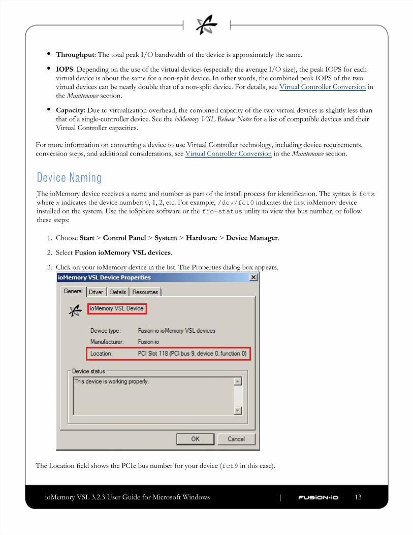
Device NamingThe ioMemory device receives a name and number as part of the install process for identification. The syntax is fctxwhere indicates the device number: 0, 1, 2, etc. For example, indicates the first ioMemory devicex /dev/fct0installed on the system. Use the ioSphere software or the utility to view this bus number, or followfio-statusthese steps:
Choose > > > > .Start Control Panel System Hardware Device Manager
Select .Fusion ioMemory VSL devices
Click on your ioMemory device in the list. The Properties dialog box appears.
The Location field shows the PCIe bus number for your device ( in this case).fct9
ioMemory VSL 3.2.3 User Guide for Microsoft Windows | __________________ ___ ___ 14
1.
2.
3.
4.
5.
6.
Adding a File SystemWith ioMemory device(s) and ioMemory VSL software installed, you can now use the Windows Disk Management
utility to make your device available to applications. Typically, Windows detects the new device, initializes it, and
displays it in Disk Management. You can then add partitions, format a volume, or create a RAID configuration on
your ioMemory device using the standard Windows procedures (see the Windows Disk Management Utility
documentation for more details).
Devices with >2TB Capacities
Devices with capacities greater than 2TB, such as the device, require the following partition types:3.2TB ioScale
Single device: GPT (GUID Partition Table)
Multiple devices (for a RAID configuration): Dynamic Disk
These devices also require sector sizes greater than 512B (we recommend 4KB sectors). When you
format these devices using fio-format, the default sector size is 4KB.
If Windows does not initialize the device, you can do so manually. To initialize an ioMemory device,
Select > .Start Control Panel
Click .Administrative Tools
Click .Computer Management
Click in the Storage section of the console tree.Disk Management
Locate and right-click the ioMemory device in the list of storage devices on the right. (If the ioMemory device
does not appear in the list, choose from the Action menu. You may also need to restart yourRescan Disks
computer to display the ioMemory device in the list.)
Click .Initialize Disk
You can now use the Disk Management Utility to add a file system to your ioMemory device.
Creating a RAID ConfigurationYou can use your ioMemory device as part of a RAID configuration with one or more additional ioMemory devices.
To do so, you must format your ioMemory devices as dynamic volumes. In turn, you can then use these dynamic
volumes to create multi-disk RAID configurations (spanned, striped, mirrored, or RAID 5).
For specific steps to perform a RAID configuration, see the Windows Disk Management Utility documentation for
details.
ioMemory VSL 3.2.3 User Guide for Microsoft Windows | __________________ ___ ___ 15
If you are using RAID1/Mirroring and one device fails, be sure to run a fio-format on the replacement device
(not the remaining good device) before rebuilding the RAID.
Using the Device as SwapTo safely use the ioMemory device as swap space, you need to use the utility to pass a specialfio-configpre-allocation parameter.
For example:
fio-config -p FIO_PREALLOCATE_MEMORY 1072,4997,6710,10345
Where 1072,4997,6710,10345 are device serial numbers obtained from (do not use adapter serialfio-statusnumbers).
A 4K sector size format is required for swap—this reduces the software memory footprint. See the fio-formatutility for information on changing the device sector sizes.
Be sure to provide the serial numbers for the ioMemory device, not the adapter.
FIO_PREALLOCATE_MEMORY is necessary to have the device usable as swap space. This will ensure the device
is crash-free during operation. See for more information on setting this parameter.fio-config
You must have enough RAM available to enable the ioMemory device with pre-allocation enabled for use as
swap. Attaching an ioMemory device, with pre-allocation enabled, without sufficient RAM may result in the loss
of user processes and system instability.
Consult the for RAM requirements with this version of the ioMemory VSL softwareL.ioMemory VSL Release Notes
The parameter is recognized by the ioMemory VSL software at load time, butFIO_PREALLOCATE_MEMORYthe requested memory is not actually allocated until the specified device is attached.
Understanding TRIM SupportWith this version of the ioMemory VSL software, TRIM (also known as Discard) is enabled by default on many
.operating systems
TRIM addresses an issue unique to solid-state storage. When a user deletes a file, the device does not recognize that it
ioMemory VSL 3.2.3 User Guide for Microsoft Windows | __________________ ___ ___ 16
can reclaim the space. Instead the device assumes the data is valid.
TRIM is a feature on newer operating systems. It informs the device of logical sectors that no longer contain valid user
data. This allows the wear-leveling software to reclaim that space (as reserve) to handle future write operations.
For a complete description of TRIM support on Windows, see the appendix.TRIM Support
Windows does not support TRIM with a RAID 5 configuration.
TRIM on Windows Server 2008 R2
Windows Server 2008 R2 has built-in TRIM support. With this operating system, ioMemory devices work with
Windows TRIM commands by default.
TRIM on Windows Server 2003 and Windows Server 2008 R1
Windows TRIM is not built into Windows Server 2003 or Windows Server 2008 R1. However, the Fusion-io TRIM
service is installed with the Windows ioMemory VSL software and it provides the necessary TRIM operations.
The Fusion-io TRIM service is enabled by default, unless it detects an operating system that supports TRIM (such as
Windows Server 2008 R2). You can disable the Fusion-io TRIM service by using the utility. See fio-trim-config for more details.fio-trim-config

ioMemory VSL 3.2.3 User Guide for Microsoft Windows | __________________ ___ ___ 17
Performance and TuningioMemory devices provide high bandwidth, high Input/Output per Second (IOPS), and are specifically designed to
achieve low latency.
As ioMemory devices improve IOPS and low latency, the device performance may be limited by operating system
settings and BIOS configuration. These settings may need to be tuned to take advantage of the revolutionary
performance of ioMemory devices.
While Fusion-io devices generally perform well out of the box, this section describes some of the common areas where
tuning may help achieve optimal performance.
Disable CPU Frequency ScalingDynamic Voltage and Frequency Scaling (DVFS) are power management techniques that adjust the CPU voltage
and/or frequency to reduce power consumption by the CPU. These techniques help conserve power and reduce the
heat generated by the CPU, but they adversely affect performance while the CPU transitions between low-power and
high-performance states.
These power-savings techniques are known to have a negative impact on I/O latency and IOPS. When tuning for
performance, you may benefit from reducing or disabling DVFS completely, even though this may increase power
consumption.
DVFS, if available, is often configurable as part of your operating systems power management features as well as
within your system's BIOS interface. Within the operating system and BIOS, DVFS features are often found under the
Advanced Configuration and Power Interface (ACPI) sections; consult your computer documentation for details.
Limiting APCI C-StatesNewer processors have the ability to go into lower power modes when they are not fully utilized. These idle states are
known as ACPI C-states. The state is the normal, full power, operating state. Higher C-states ( , , , etc.) areC0 C1 C2 C3lower power states.
While ACPI C-states save on power, they can have a negative impact on I/O latency and maximum IOPS. With each
higher C-state, typically more processor functions are limited to save power, and it takes time to restore the processor
to the state.C0
When tuning for maximum performance you may benefit from limiting the C-states or turning them off completely,
even though this may increase power consumption.
ioMemory VSL 3.2.3 User Guide for Microsoft Windows | __________________ ___ ___ 18
Setting ACPI C-State Options
If your processor has ACPI C-states available, you can typically limit or disable them in the BIOS interface (sometimes
referred to as a Setup Utility). APCI C-states may be part of of the Advanced Configuration and Power Interface
(ACPI) menu. Consult your computer documentation for details.
Setting NUMA AffinityServers with a NUMA (Non-Uniform Memory Access) architecture may require special installation instructions in
order to maximize ioMemory device performance. This includes most multi-socket servers.
On some servers with NUMA architecture, during system boot, the BIOS will not associate PCIe slots with the correct
NUMA node. Incorrect mappings result in inefficient I/O handling that can significantly degrade performance. To
prevent this, you must manually assign ioMemory devices optimally among the available NUMA nodes.
For information on setting NUMA affinity, see .Appendix G- NUMA Configuration
Setting the Interrupt Handler AffinityDevice latency can be affected by placement of interrupts on NUMA systems. We recommend placing interrupts for a
given device on the same NUMA node that the application is issuing I/O from. If the CPUs on this node are
overwhelmed with user application tasks, in some cases it may benefit performance to move the the interrupts to a
remote node to help load-balance the system.
Many operating systems will attempt to dynamically place interrupts across the nodes, and generally make good
decisions.
Windows IRQ Policy
By default, Windows uses a policy of and a priority of ,IrqPolicyAllCloseProcessors IrqPriorityNormalwhich should work best for most applications.
If manual tuning is needed, Windows provides the Interrupt Affinity Policy Tool. Information on this tool can be
found at: . The settings that the application changeshttp://msdn.microsoft.com/en-us/windows/hardware/gg463378
are listed at: .http://msdn.microsoft.com/en-us/library/ff547969(v=vs.85).aspx
With Windows Sever 2008 or newer on a machine with more than 64 processors, there's an additional GroupPolicyparameter that can be set through the registry in order to set the affinity to a different processor group. This is
documented at: .http://msdn.microsoft.com/en-us/windows/hardware/gg463349
ioMemory VSL 3.2.3 User Guide for Microsoft Windows | __________________ ___ ___ 19
MaintenanceThe ioMemory VSL software includes utilities for maintaining the device.
GUI MangementioSphere software is a free browser-based solution for managing ioMemory devices. ioSphere software and
documentation are available as a separate download . in the ioSphere download folder
The ioSphere software can perform:
Firmware upgrades
Low-level formatting
Attach and detach actions
Device status and performance information
Command-line UtilitiesThe Windows Setup package also includes several command-line utilities for managing your ioMemory device:
fio-attach
fio-beacon
fio-bugreport
fio-config
fio-detach
fio-format
fio-pci-check
fio-status
fio-sure-erase
fio-trim-config
fio-update-iodrive

ioMemory VSL 3.2.3 User Guide for Microsoft Windows | __________________ ___ ___ 20
Each of these is described in detail in .Appendix C- Command-line Utilities
Enabling PCIe Power OverrideIf you have installed any products with multiple ioMemory devices, such as the ioDrive Duo device, the device may
require additional power to properly function (beyond the minimum 25W provided by PCIe Gen2 slots). Even if
additional power is not required for your device, all dual ioMemory devices that receive additional power may benefit
with improved performance.
ioDrive2 Duo devices have additional power in order to properly function. For more information on whichmust
devices require additional power, see the section on in the Power Cables for Multi-device Products ioMemory Hardware
.Installation Guide
This additional power may be provided in two ways:
External Power Cable: This cable ships with all dual ioMemory devices. See the ioMemory Hardware Installation
for information on installing this cable.Guide
When a power cable is used, all of the power is drawn from the cable and no power is drawn from the
PCIe slot.
Enabling Full Slot Power Draw: Some PCIe slots provide additional power (often up to 75W of power). If
your slot is rated to provide at least 55W, you may allow the device to draw full power from the PCIe slot by
setting an ioMemory VSL module parameter. For more information on enabling this override parameter, see
the instructions below in the next section.
This parameter overrides the setting that prevents device(s) from drawing more than 25W from the PCIe
slot. The parameter is enabled per device (using device serial numbers). Once the setting is overridden,
each device may draw up to the full 55W needed for peak performance.
WARNING
If the slot is not capable of providing the needed amount of power, enabling full power draw from the
PCIe slot may result in malfunction or even damage server hardware. You are responsible for any damage
to equipment due to improper use of this override parameter and Fusion-io expressly disclaims any
liability for any damage arising from such improper use. Contact Fusion-io Customer Support if there are
any questions or concerns about the override parameter use.
Before you enable this override parameter, ensure that each PCIe slot you will use is rated to provide enough power
for all slots, devices, and server accessories. Consult the server documentation, BIOS interface, setup utility, and/or
use (if available) to determine the slot power limits.fio-pci-check

ioMemory VSL 3.2.3 User Guide for Microsoft Windows | __________________ ___ ___ 21
Confirm with Server Manufacturer
Contact the server manufacturer to confirm the power limits and capabilities of each slot, as well as the entire
system.
The following are important considerations:
If you are installing more than one dual ioMemory device and enabling the override parameter for each device,
make sure the motherboard is rated to provide 55W power to each slot used.
For example, some motherboards safely provide up to 75W to any one slot, but run into power
constraints when multiple slots are used to provide that much power. Installing multiple devices in this
situation may also result in server hardware damage. Consult with the manufacturer to determine the total
PCIe slot power available.
The override parameter, if enabled correctly, will persist in the system, and will enable full power draw on an
enabled device even if the device is removed and then placed in a different slot within the same system. If the
device is placed in a slot that is not rated to provide 55W of power, you may damage your server hardware.
This override parameter is a setting for the ioMemory VSL software per server, and is not stored in the device.
When moved to a new server, the device will default to the 25W power limit until an external power cable is
added or this override parameter is enabled for that device in the new server. Consult with the manufacturer to
determine the total PCIe slot power available for the new server.
Enabling the Override Parameter
Determine Serial Number(s)
Before you enable this parameter, determine the for each device you will put in a compatibleadapter serial number
slot. Use the command-line utility to determine the adapter serial number(s).fio-status
Serial Number Label
You may also inspect the adapter serial number label(s) on the device(s) to determine the serial number(s).
However, as a best practice, confirm that each serial number is an adapter serial number by running
. The adapter serial number label resides on the back of all ioDrive Duo devices and ioDrive2 Duofio-statusdevices. On ioDrive Duo devices, it is on the PCB component that is attached to the PCIe connector.
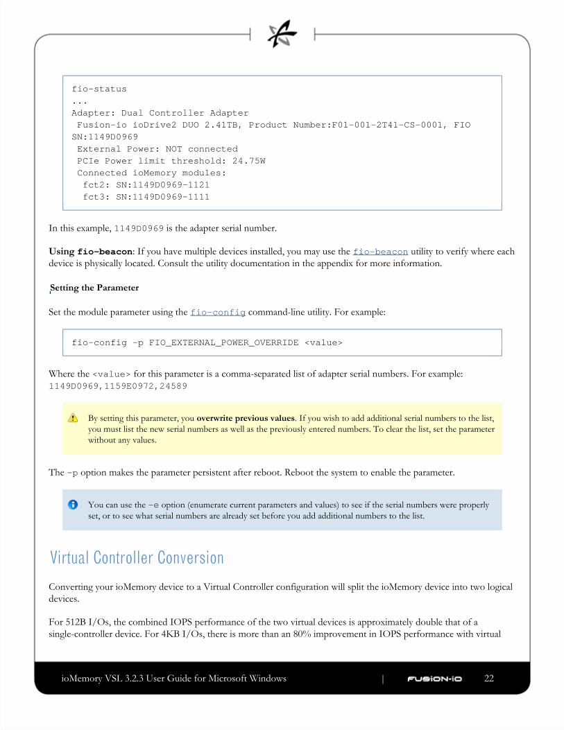
Using fio-status: Run the command-line utility. Sample output:fio-status
ioMemory VSL 3.2.3 User Guide for Microsoft Windows | __________________ ___ ___ 22
fio-status...Adapter: Dual Controller Adapter Fusion-io ioDrive2 DUO 2.41TB, Product Number:F01-001-2T41-CS-0001, FIOSN:1149D0969 External Power: NOT connected PCIe Power limit threshold: 24.75W Connected ioMemory modules: fct2: SN:1149D0969-1121 fct3: SN:1149D0969-1111
In this example, is the adapter serial number.1149D0969
Using fio-beacon: If you have multiple devices installed, you may use the utility to verify where eachfio-beacondevice is physically located. Consult the utility documentation in the appendix for more information.
Setting the Parameter
Set the module parameter using the command-line utility. For example:fio-config
fio-config -p FIO_EXTERNAL_POWER_OVERRIDE <value>
Where the for this parameter is a comma-separated list of adapter serial numbers. For example: <value>1149D0969,1159E0972,24589
By setting this parameter, you . If you wish to add additional serial numbers to the list,overwrite previous values
you must list the new serial numbers as well as the previously entered numbers. To clear the list, set the parameter
without any values.
The option makes the parameter persistent after reboot. Reboot the system to enable the parameter.-p
You can use the option (enumerate current parameters and values) to see if the serial numbers were properly-eset, or to see what serial numbers are already set before you add additional numbers to the list.
Virtual Controller ConversionConverting your ioMemory device to a Virtual Controller configuration will split the ioMemory device into two logical
devices.
For 512B I/Os, the combined IOPS performance of the two virtual devices is approximately double that of a
single-controller device. For 4KB I/Os, there is more than an 80% improvement in IOPS performance with virtual
ioMemory VSL 3.2.3 User Guide for Microsoft Windows | __________________ ___ ___ 23
1.
devices. For 16KB and larger I/Os, there is no improvement of total IOPS performance over a non-Virtual Controller
configuration.
Latency in the virtual devices is unaffected, and the combined bandwidth of the two virtual devices is the same as it
would be without the split. Due to the overhead of an additional device, the combined capacity of the two virtual
devices is slightly less than that of a single-controller device.
Splitting a single physical device into multiple virtualized devices, or merging multiple virtualized devices back to a
single physical device requires a low-level format, which will erase all of the data on the device. Be sure to back up all
of your data.
Supported Devices
Only relatively new devices (with few writes performed) may be split or merged. Devices with too much wear are
unsuitable for converting to or from a Virtual Controller configuration. Merging virtual devices may also result in
additional wear (depending on the wear differences of the two virtual devices).
To be suitable for splitting or merging, devices (including Virtual Controller devices) must have 90% or more of their
remaining rated endurance of Petabytes Written (PBW). This rating as well as the current percentage remaining is
visible in with the option. For example:fio-status -a
fio-status /dev/fct1 -a... Rated PBW: 17.00 PB, 99.95% remaining
In the above example, the device is suitable for conversion because it has more than 90% of the rated PBW remaining.
If you attempt to merge or split a device that does not support Virtual Controller technology or a device that has too
much wear, the update utility will not allow the conversion and the firmware upgrade will not take place. See the
Release Notes for a list of devices that support Virtual Controller technology and their capacities after the conversion.
Multi-device Products
For products with more than one ioMemory device, such as an ioDrive2 Duo device, you must configure all of the
ioMemory devices to Virtual Controller technology at the same time. All of the devices must also be merged at the
same time. For example, the two ioMemory devices in an ioDrive2 Duo device will be converted into four virtual
devices. The utility will not allow a conversion if you attempt to split or merge only one physical device in a
multi-device product.
Splitting Controllers
Be sure to use firmware that supports Virtual Controller technology. Consult the Release Notes to determine if the
firmware for that release supports Virtual Controller technology.
Back up all of your data. Because a low-level format is needed to complete the conversion, all of the user data
on your device will be erased.
ioMemory VSL 3.2.3 User Guide for Microsoft Windows | __________________ ___ ___ 24
2.
3.
4.
5.
6.
1.
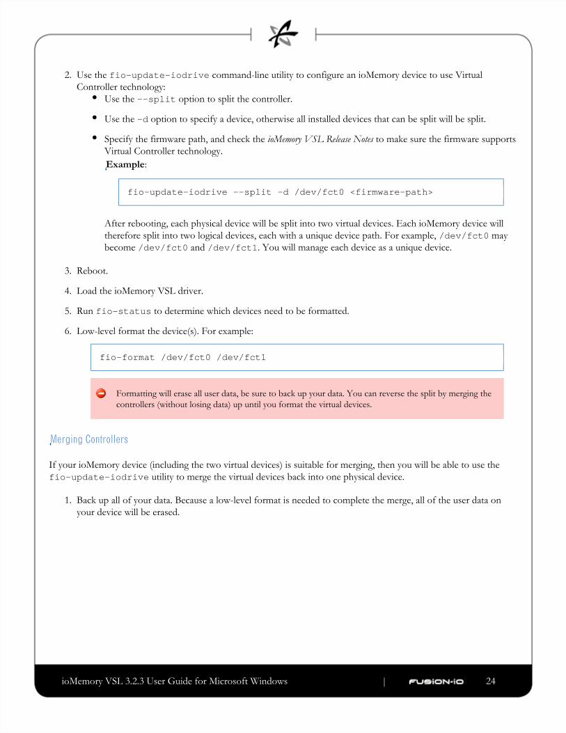
Use the command-line utility to configure an ioMemory device to use Virtualfio-update-iodriveController technology:
Use the option to split the controller.--split
Use the option to specify a device, otherwise all installed devices that can be split will be split.-d
Specify the firmware path, and check the to make sure the firmware supportsioMemory VSL Release Notes
Virtual Controller technology.
Example:
fio-update-iodrive --split -d /dev/fct0 <firmware-path>
After rebooting, each physical device will be split into two virtual devices. Each ioMemory device will
therefore split into two logical devices, each with a unique device path. For example, may/dev/fct0become and . You will manage each device as a unique device./dev/fct0 /dev/fct1
Reboot.
Load the ioMemory VSL driver.
Run to determine which devices need to be formatted.fio-status
Low-level format the device(s). For example:
fio-format /dev/fct0 /dev/fct1
Formatting will erase all user data, be sure to back up your data. You can reverse the split by merging the
controllers (without losing data) up until you format the virtual devices.
Merging Controllers
If your ioMemory device (including the two virtual devices) is suitable for merging, then you will be able to use the
utility to merge the virtual devices back into one physical device.fio-update-iodrive
Back up all of your data. Because a low-level format is needed to complete the merge, all of the user data on
your device will be erased.
ioMemory VSL 3.2.3 User Guide for Microsoft Windows | __________________ ___ ___ 25
2.
3.
4.
5.
6.
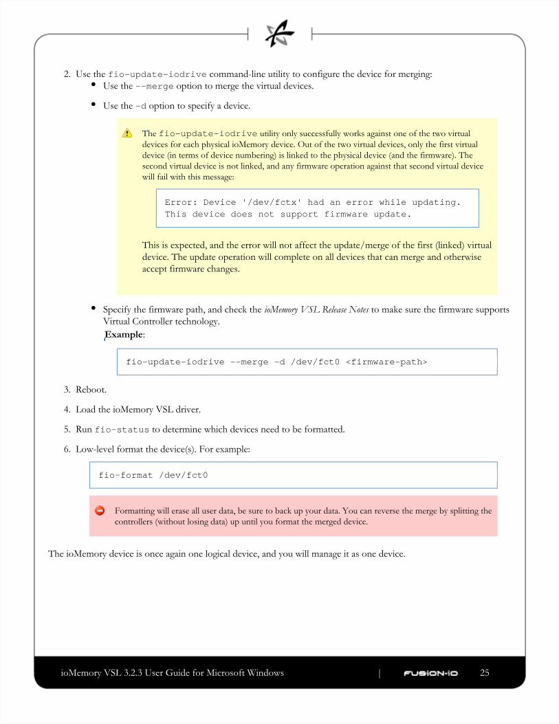
Use the command-line utility to configure the device for merging:fio-update-iodriveUse the option to merge the virtual devices.--merge
Use the option to specify a device.-d
The utility only successfully works against one of the two virtualfio-update-iodrivedevices for each physical ioMemory device. Out of the two virtual devices, only the first virtual
device (in terms of device numbering) is linked to the physical device (and the firmware). The
second virtual device is not linked, and any firmware operation against that second virtual device
will fail with this message:
Error: Device '/dev/fctx' had an error while updating.This device does not support firmware update.
This is expected, and the error will not affect the update/merge of the first (linked) virtual
device. The update operation will complete on all devices that can merge and otherwise
accept firmware changes.
Specify the firmware path, and check the to make sure the firmware supportsioMemory VSL Release Notes
Virtual Controller technology.
Example:
fio-update-iodrive --merge -d /dev/fct0 <firmware-path>
Reboot.
Load the ioMemory VSL driver.
Run to determine which devices need to be formatted.fio-status
Low-level format the device(s). For example:
fio-format /dev/fct0
Formatting will erase all user data, be sure to back up your data. You can reverse the merge by splitting the
controllers (without losing data) up until you format the merged device.
The ioMemory device is once again one logical device, and you will manage it as one device.
ioMemory VSL 3.2.3 User Guide for Microsoft Windows | __________________ ___ ___ 26
1.
2.
3.
4.
1.
2.
3.
4.
5.
6.
7.
8.
9.
10.
Uninstalling the SoftwareTo uninstall the ioMemory VSL software,
Go to > .Start Control Panel
Click .Programs & Files
Select the entry.Fusion-io ioMemory VSL
Click .Uninstall
Windows uninstalls the ioMemory VSL folder along with all files and folders.
The ioMemory VSL utilities are uninstalled with this procedure. If you are upgrading to a newer version ofnot
the ioMemory device, you do not need to manually uninstall these utilities. However, if you are uninstalling the
software completely, or planning on installing an earlier version of the ioMemory VSL software, you should
manually remove the following folder and its contents: C:\Program Files\Common Files\VSLUtils
Upgrading the ioMemory VSL- Non-RAID Configuration
Be sure to read the document that comes with each new release as well as theseioMemory VSL Release Notes
installation instructions to ensure no loss of data when performing upgrades.
To upgrade the ioMemory VSL software in a non-RAID configuration:
Follow the steps in earlier.Uninstalling the Software
Download the latest ioMemory VSL software . from http://support.fusionio.com
Either unzip or run the Windows package to copy the files to a convenient directory.
Go to > .Start Control Panel
Click .Administrative Tools
Click .Computer Management
Click in the console tree at the left.Device Manager
Expand the Fusion-io Devices item.
Right-click the desired device.
Click . If needed, refer to for details on theUpdate ioMemory device Appendix B- Manual Installation
remaining steps to install the updated ioMemory device.
ioMemory VSL 3.2.3 User Guide for Microsoft Windows | __________________ ___ ___ 27
1.
2.
3.
4.
5.
6.
7.
8.
9.
10.
Windows now detects your ioMemory device(s) with the upgraded ioMemory device.
Upgrading the ioMemory VSL with a RAID Configuration
Be sure to read the document that comes with each new release as well as theseioMemory VSL Release Notes
installation instructions to ensure no loss of data when performing upgrades.
To upgrade the ioMemory VSL software with a RAID configuration in place:
Shut down any applications that are accessing the ioMemory devices.
Open the ioMemory VSL utilities folder. (The default location for this release is C:\Program.)Files\Common Files\VSL Utils
Double-click the file to add a key to the Windows registry. Your ioMemoryAutoAttachDisable.regdevice now will not automatically attach the next time you restart the computer.
Uninstall the ioMemory VSL software in .Windows Add/Remove Programs
Restart the computer.
Download the latest ioMemory VSL software package . from http://support.fusionio.com
Unzip and install the ioMemory VSL software. While finishing installation, click the "No" button to select a
manual restart.
Open the ioMemory VSL utilities folder. (The default location is C:\Program Files\Common Files\VSL)Utils
Double-click the file to reset the key in the Windows registry. Your ioMemoryAutoAttachEnable.regdevice will now automatically attach the next time you restart the computer.
Update the firmware of the devices. Follow the steps in , which is the nextUpgrading the Device Firmware
section.
Restart the computer after the firmware upgrade is complete. The ioMemory VSL Check Utility will run at next
boot.
Windows now detects your devices in the RAID configuration with the upgraded software.
ioMemory VSL 3.2.3 User Guide for Microsoft Windows | __________________ ___ ___ 28
Upgrading the Device Firmware
Viewing the Firmware Version
The firmware version can be found in the Windows Event Log. It is reported by the ioSphere software and the
command-line utility. For more details, see the ioSphere software User Guide or in fio-status fio-status.Appendix C- Command-line Utilities
Upgrade Path
There is a specific upgrade path that you must take when upgrading ioMemory device. Consult the ioMemory VSL
for this ioMemory VSL software release before upgrading ioMemory devices.Release Notes
Performing the Upgrade
You should back up the data on the device prior to any upgrade as a precaution.
To perform the upgrade, use either the ioSphere software (see the ) or the ioSphere software User Guide
command-line utility.fio-update-iodrive
Your ioMemory device may have a minimum firmware label affixed (for example, "MIN FW: XXXXXX"). This label
indicates the minimum version of the firmware that is compatible with your device.
Do not attempt to downgrade the firmware on any ioMemory device.
When installing a new ioMemory device along with existing devices, you must upgrade all of the currently installed
devices to the latest available versions of the firmware and ioMemory VSL software before installing the new devices.
Consult the for this ioMemory VSL software release for any upgrade considerations.ioMemory VSL Release Notes
Upgrading VMware Guest OS
If you are using your ioMemory device with a VMware guest OS (using VMDirectPathIO), you must cycle the power
on the host after you upgrade the device(s). Just restarting the virtual machine won't apply the change.
DefragmentationThe ioMemory device does not need to be defragmented. Some versions of Windows, however, run defragmentation
as a scheduled task automatically. If necessary, you should turn off automatic defragmentation.
ioMemory VSL 3.2.3 User Guide for Microsoft Windows | __________________ ___ ___ 29
1.
2.
3.
Unmanaged Shutdown IssuesUnmanaged shutdown due to power loss or other circumstances can force the ioMemory device to perform a
consistency check during restart. This may take several minutes or more to complete and is shown by a progress
percentage during Windows startup.
You can cancel this consistency check by pressing Esc during the first 15 seconds after the "Fusion-io Consistency
Check" message appears at the prompt. If you choose to cancel the check, however, the ioMemory device(s) will
remain unavailable to users until the check is done. (You can perform this check later on using ioSphere software's
Attach function).
Although data written to the ioMemory device will not be lost due to unmanaged shutdowns, important data structures
may not have been properly committed to the device. This consistency check repairs these data structures.
Disabling Auto-AttachThe ioMemory VSL software defaults to automatically attach (auto-attach) all installed ioMemory devices to the
operating system. (If the ioMemory device does not attach, it will not be available to applications or users.) You can
disable auto-attach to assist in troubleshooting or diagnostics.
To disable auto-attach:
Open the ioMemory VSL Utilities folder. (The default location is C:\Program Files\Common).Files\VSL Utils
Double-click the file.autoattachdisable.reg
If you receive a prompt at this point, confirm that you want to modify the registry.
This creates a new DWORD parameter registry key called in:AutoAttach
HKEY_LOCAL_MACHINE\SYSTEM\CurrentControlSet\Services\fiodrive\Parameters
Once you restart your system, your ioMemory device will no longer automatically attach until you re-enable auto attach
(see )Enabling Auto-Attach
When you finish troubleshooting the ioMemory VSL software issue, use or the ioSphere software tofio-attachattach the ioMemory device(s) and make them available to Windows.
ioMemory VSL 3.2.3 User Guide for Microsoft Windows | __________________ ___ ___ 30
1.
2.
3.
Enabling Auto-AttachTo re-enable auto-attach after disabling it using the method described in :Disabling Auto-Attach
Open the ioMemory VSL utilities folder. (The default location is C:\Program Files\Common Files\VSL).Utils
Double-click the file.autoattachenable.reg
If you receive a prompt at this point, confirm that you want to modify the registry.
This resets the AutoAttach parameter in the Registry. The next time you restart your Windows system, your ioMemory
device will automatically attach.

ioMemory VSL 3.2.3 User Guide for Microsoft Windows | __________________ ___ ___ 31
Monitoring and Managing DevicesFusion-io provides many tools for managing your ioMemory devices. These tools will allow you to monitor the devices
for errors, warnings, and potential problems. They will also allow you to manage the devices including performing the
following functions:
Firmware upgrades
Low-level formatting
Attach and detach actions
Device status and performance information
Configuring Swap and Paging
Generating bug reports
Management ToolsFusion-io has provided several tools for monitoring and managing ioMemory devices. These include stand-alone tools
that require no additional software and data-source tools that can be integrated with other applications.
Consider the descriptions of each tool to decide which tool (or combination of tools) best fits your needs.
The ioMemory VSL software does print some error messages to the system logs, and while these messages are
very useful for troubleshooting purposes, the VSL software log messages are not designed for continual
monitoring purposes (as each is based on a variety of factors that could produce different log messages depending
on environment and use case). For best results, use the tools described in this section to regularly monitor your
devices.
Stand-alone Tools
These stand-alone tools do not require any additional software.
Command-line Utilities: These utilities are run manually in the terminal. The utility providesfio-statusstatus for all devices within a host. The other utilities allow you to perform other management functions. See
Appendix A- Utilities Reference for full details.

ioMemory VSL 3.2.3 User Guide for Microsoft Windows | __________________ ___ ___ 32
ioSphere Software: The GUI browser-based ioSphere software allows you to monitor and manage every
ioMemory device installed in multiple hosts across your network. It collects all of the alerts for all ioMemory
devices and displays them in the Alert Tab. You may also set up the ioSphere software to send email or SMS
messages for specific types of alerts or all alerts. The software packages and documentation are available from
.http://support.fusionio.com
Data-source Tools
These data-source tools provide comprehensive data, just like the stand-alone tools, but they do require integration
with additional software. At a minimum, some tools can interface with a browser. However, the benefit of these tools is that
they can be integrated into existing management software that is customized for your organization.
These tools are available as separate downloads. See the for more information.ioMemory VSL Release Notes
SNMP Subagent: The Fusion-io SNMP AgentX subagent allows you to monitor and manage your ioMemory
devices using the Simple Network Management Protocol. You can use a normal SNMP browser, or customize
your existing application to interface with the subagent.
SMI-S CIM Provider: The CIM provider allows you to monitor and manage your devices using the Common
Information Model. You can use a normal CIM browser, or customize your existing application to interface
with the CIM provider.
ioMemory VSL Management SDK: This C programing API allows you to write customize applications for
monitoring and managing ioMemory devices.
Example Conditions to MonitorThis section gives examples of conditions you can monitor. It is intended as an introduction and not as a
comprehensive reference. These conditions will have slightly different names, states, and values, depending on the tool
you choose. For example, an SNMP MIB may have a different name than a SMI-S object or an API function.
In order to properly monitor these conditions, you should become familiar with the tool you choose to implement and
read the documentation for that tool. You may also discover additional conditions that you wish to frequently monitor.
For quick reference, the possible states/values of these conditions are described as Normal ( ), Caution/AlertGREEN
( ), or Error/Warning ( ). You may implement your own ranges of acceptable states/values, especially ifYELLOW RED
you use a data-source tool.
Device Status
All of the monitoring tools return information on the status of the ioMemory devices, including the following states:
GREEN Attached
YELLOW Detached, Busy (including: Detaching, Attaching, Scanning, Formatting, and Updating)
RED Minimal Mode, Powerloss Protect Disabled

ioMemory VSL 3.2.3 User Guide for Microsoft Windows | __________________ ___ ___ 33
If the device is in Minimal Mode, the monitoring tool can display the reason for the Minimal Mode status.
Required Actions
If the device is in Minimal Mode, the action will depend on the reason. For example, if the reason is outdated
firmware, then you will need to update the firmware.
Temperature
ioMemory devices require adequate cooling. In order to prevent thermal damage, the ioMemory VSL software will
start throttling write performance once the on-board controller reaches a specified temperature. If the controller
temperature continues to rise, the software will shut down the device once the controller temperature reaches the
maximum operating temperature.
These temperatures depend on the device. Newer ioMemory devices have higher thermal tolerances. Consult the
to determine the thermal tolerances of all devices you will monitor. ioMemory Hardware Installation Guide This table
(93°C throttling, 100°C shutdown).uses the thermal tolerances for newer devices
GREEN <93°C
YELLOW 93-99°C
RED 100°C
You may wish to shift the conditions by a few degrees so the YELLOW condition exists before throttling occurs. For
example:
GREEN <90°C
YELLOW 90-96°C
RED 97°C
Required Actions
If the temperature is at or approaching the condition, you must increase the cooling for your system. ThisYELLOW
may include increasing the fan speed, bringing down the ambient temperature, reducing write load, or moving the
device to a different slot.
Health Reserves Percentage
ioMemory devices are highly fault-tolerant storage subsystem with many levels of protection against component failure
and the loss nature of solid-state storage. As in all storage subsystems, component failures may occur.
By pro-actively monitoring device age and health, you can ensure reliable performance over the intended product life.
The following table describes the Health Reserve conditions.
GREEN >10%

ioMemory VSL 3.2.3 User Guide for Microsoft Windows | __________________ ___ ___ 34
YELLOW 0-10%
RED 0%
At the 10% healthy threshold, a one-time warning is issued. At 0%, the device is considered unhealthy. It enters
mode. After the 0% threshold, the device will soon enter mode.write-reduced read-only
For complete information on Health Reserve conditions and their impact on performance, see Appendix B-
Monitoring the Health of ioMemory Devices.
Required Actions
The device needs close monitoring as it approaches 0% reserves and goes into write-reduced mode, which will result in
reduced write performance. Prepare to replace the device soon.
Write (Health Reserves) Status
In correlation with the Health Reserves Percentage, the management tools will return write states similar to these:
GREEN Device is healthy
YELLOW Device is getting close to entering reduced write mode.
RED Device has entered reduced-write or read-only mode to preserve the flash from further wearout.
Required Actions
The device needs close monitoring as it approaches 0% reserves and goes into write-reduced mode, which will result in
reduced write performance. Prepare to replace the device soon.
Device LED IndicatorsIf you have physical access to the devices, you can use the LED indicators to monitor their status.
Each ioMemory device includes three LEDs showing drive activity or error conditions. The LEDs on your device
should be similar to one of these configurations:

ioMemory VSL 3.2.3 User Guide for Microsoft Windows | __________________ ___ ___ 35
This table explains the information that these LEDs convey:
ioFX devices have an additional LED that illuminates the ioFX logo. This LED has no functional significance and
it cannot be turned off.

ioMemory VSL 3.2.3 User Guide for Microsoft Windows | __________________ ___ ___ 36
Appendix A- Troubleshooting Event Log MessagesThe Windows System Event Log displays the following messages concerning the ioMemory device: Informational,
Warnings, and Errors.
Each ioMemory device is numbered from upwards. Use the utility or ioSphere software to view0 fio-statusthis number for your device.
While these messages are very useful for troubleshooting purposes, the ioMemory VSL log messages are not
designed for continual monitoring purposes (as each is based on a variety of factors that could produce different
log messages depending on environment and use case). For best results, use the tools described in the Monitoring
section to regularly monitor your devices.and Managing Devices
Verbose Event Log Parameter
If you begin experiencing issues with your ioMemory devices, you should enable the ioMemoryWIN_LOG_VERBOSEVSL parameter. This will expand the extent of the ioMemory VSL error log messages in the event log and provide
additional crucial information for troubleshooting any issues.
Sample Command:
fio-config.exe -p WIN_LOG_VERBOSE 1
For more information on enabling parameters, see .fio-config

ioMemory VSL 3.2.3 User Guide for Microsoft Windows | __________________ ___ ___ 37
1.
2.
3.
4.
5.
6.
1.
2.
3.
Viewing LogsTo open the Windows Event Viewer,
Click .Start
Click and right-click .Computer Manage
Expand .Diagnostics
Expand .Event Viewer
Expand .Windows Logs
Select .System
Error Messages
The following are common Event Log error messages, along with suggested solutions:
Message Suggested Solution
Error: ioDrive(x)
firmware is too old.
The firmware must
be updated.
Use the firmware upgrade instructions in the section to update the firmware.Maintenance
Error: ioDrive
initialization failed
with error code
*0xerrorcode
Reinstall the Windows ioMemory VSL.
Remove and reseat the ioMemory device.
Remove and insert the ioMemory device in a different PCIe slot
Error: ioDrive was
not attached. Use the
utilityfio-attachto rebuild the drive.
This error may appear after an unmanaged shutdown. You can use either the fio-attachcommand-line utility or ioSphere software to re-attach the device. This attach process may take up to
ten minutes as the utility performs a consistency check on the device(s).

ioMemory VSL 3.2.3 User Guide for Microsoft Windows | __________________ ___ ___ 38
1.
2.
3.
4.
Warning: ioDrive was
not loaded because
auto-attach is
disabled.
The ioMemory device must attach to the Windows operating system to be available to users and
applications. (This attach normally occurs at boot time.) As part of this attach process, the ioMemory
VSL checks to see if there is an AutoAttach parameter in the Windows registry. If you create this
Registry parameter to disable auto-attach, the attach operation does not complete.
To attach an unattached device,
Run the ioSphere software.
Select your unattached ioMemory device from the Device Tree.
Click .Attach
Confirm the Attach operation.
Your device now attaches to the Windows operating system. To re-enable Auto-Attach at boot
time, refer to in the Maintenance section.Enabling Auto-Attach
* Where is one of the following:0xerrorcode
Error Code Description
0xFFFFFC00 Uncorrectable ECC Error
0xFFFFFBFF Uncorrectable ECC Error
0xFFFFFBFE Invalid Media Format
0xFFFFFBFD Unknown Error
Or one of the 43 standard Windows errno definitions found at
http://msdn.microsoft.com/en-us/library/t3ayayh1%28v=vs.110%29.aspx
The error code is converted to a negative number, and then reported in hexadecimal format. For example,
is converted to and is represented as , and is converted to errno=1 -1 0xFFFFFFFF errno=1024 -1024and is represented as .0xFFFFFC00
Informational Messages
The following is a common Event Log informational message:
Message Additional Information
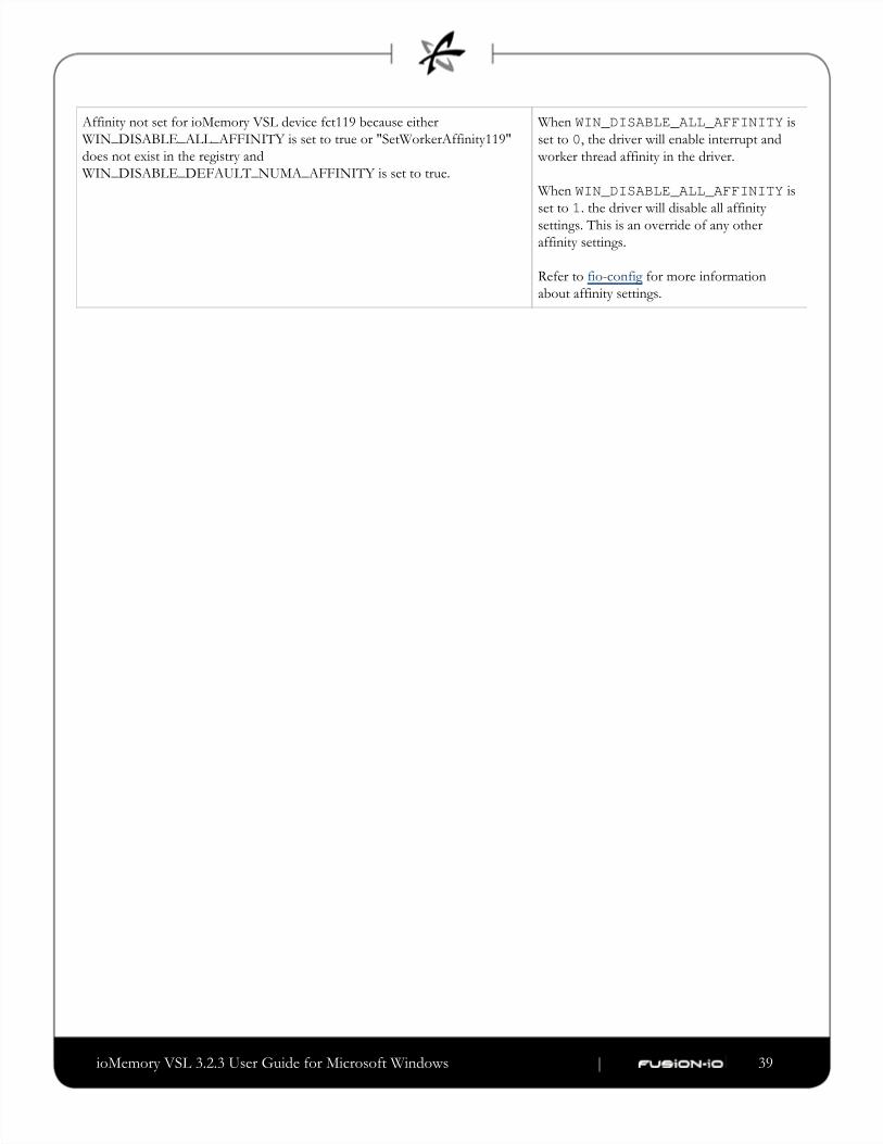
ioMemory VSL 3.2.3 User Guide for Microsoft Windows | __________________ ___ ___ 39
Affinity not set for ioMemory VSL device fct119 because either
WIN_DISABLE_ALL_AFFINITY is set to true or "SetWorkerAffinity119"
does not exist in the registry and
WIN_DISABLE_DEFAULT_NUMA_AFFINITY is set to true.
When isWIN_DISABLE_ALL_AFFINITYset to , the driver will enable interrupt and0worker thread affinity in the driver.
When isWIN_DISABLE_ALL_AFFINITYset to . the driver will disable all affinity1settings. This is an override of any other
affinity settings.
Refer to for more informationfio-config
about affinity settings.

ioMemory VSL 3.2.3 User Guide for Microsoft Windows | __________________ ___ ___ 40
1.
2.
Appendix B- Manual InstallationThe Windows Setup program will install ioMemory VSL software on your Windows operating system. However, there
are some instances where you may need to manually install the software for a particular ioMemory device, including:
After a software installation (including upgrade), ioMemory devices don't show up in fio-status.
You install new ioMemory devices on a system that has previously installed ioMemory devices and ioMemory
VSL software.
Follow the steps below for Windows Server 2008. This will ensure that the ioMemory VSLWindows Server 2003 or
software is installed for a particular device. Repeat the steps for each device, if needed.
Manual Installation on Windows Server 2003Before you manually install the ioMemory VSL software, make sure you have downloaded and run the ioMemory VSL
Windows Setup program from . This will install the ioMemory VSL software on thehttp://support.fusionio.com
system, and you will now be able to install the ioMemory VSL software for each ioMemory device.
The Windows Driver Wizard may automatically detect the new ioMemory device and starts to locate its ioMemory
VSL software after you restart the system. If this happens, you may skip to the Installation Wizard procedure below.
Choose > > > > .Start Control Panel Administrative Tools Computer Management Device Manager
Select .Fusion ioMemory VSL devices

ioMemory VSL 3.2.3 User Guide for Microsoft Windows | __________________ ___ ___ 41
3.
a.
b.
4.
5.
6.
Click on your ioMemory device(s) in the list. The Properties dialog box appears.
The device may be titled .Mass Storage Controller
If the reads , then the ioMemory VSLDevice Status This device is working properlysoftware has been installed.
If the device is not working correctly, you will need to manually install the software for that device.
Continue with the manual installation.
Close the Properties dialog box.
Right-click on the device and choose .Update Driver
Follow the instructions below.
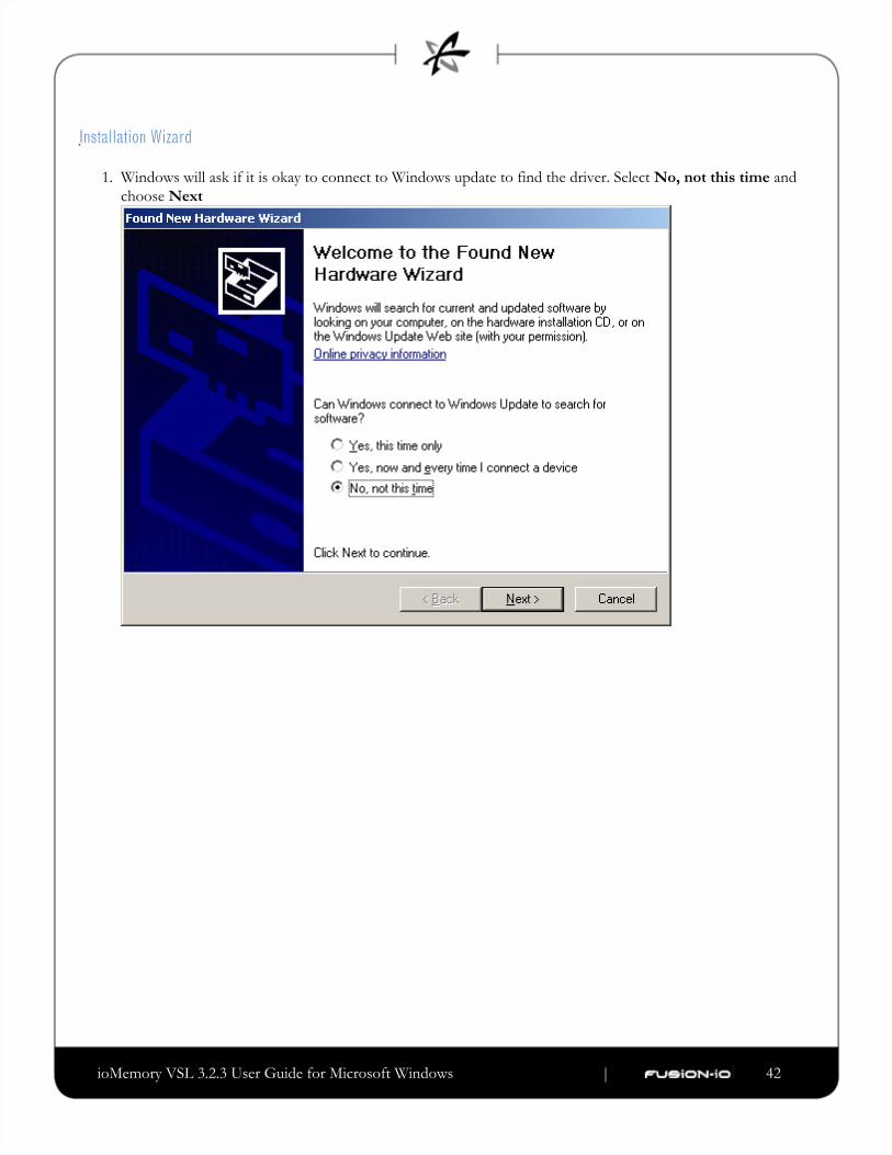
ioMemory VSL 3.2.3 User Guide for Microsoft Windows | __________________ ___ ___ 42
1.
Installation Wizard
Windows will ask if it is okay to connect to Windows update to find the driver. Select andNo, not this time
choose Next
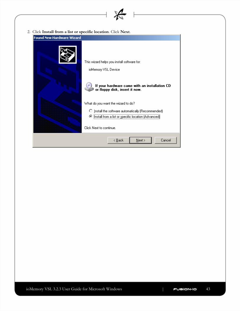
ioMemory VSL 3.2.3 User Guide for Microsoft Windows | __________________ ___ ___ 43
2. Click . Click . Install from a list or specific location Next
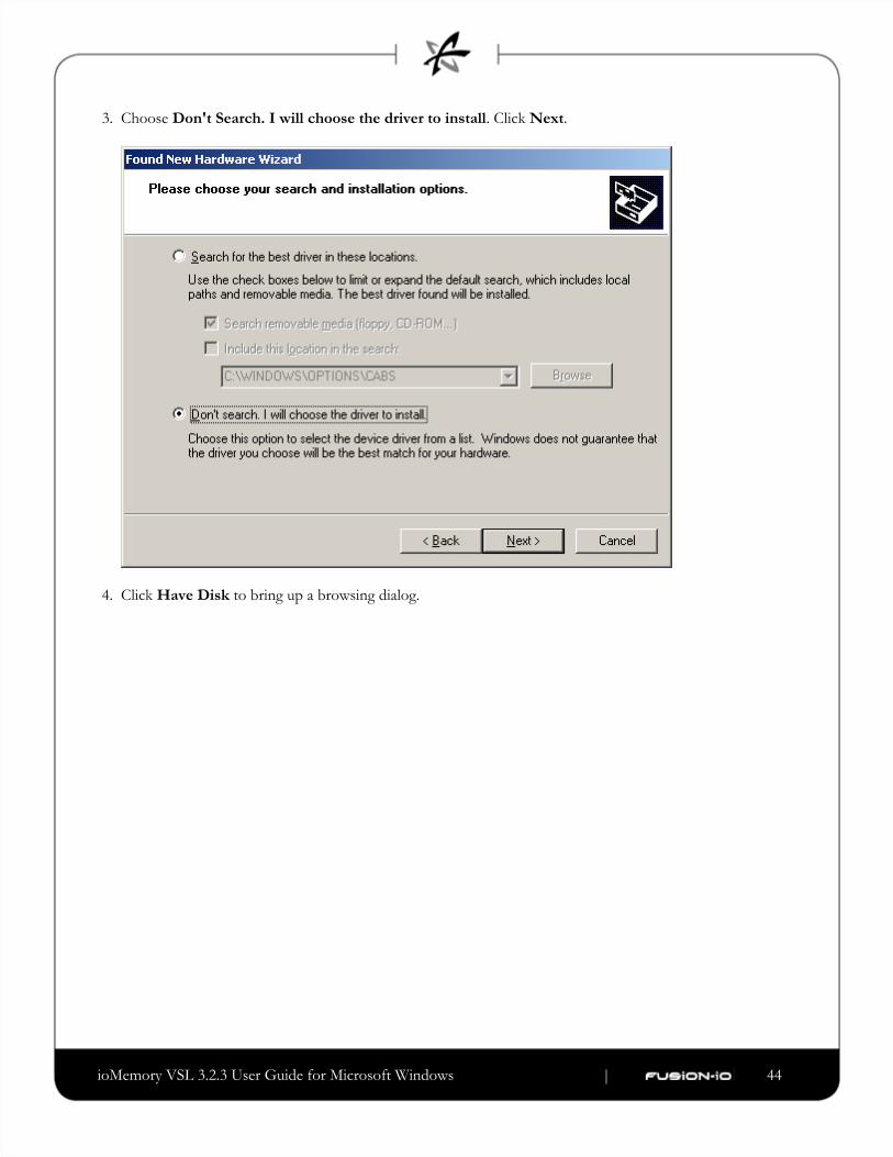
ioMemory VSL 3.2.3 User Guide for Microsoft Windows | __________________ ___ ___ 44
3.
4.
Choose . Click . Don't Search. I will choose the driver to install Next
Click to bring up a browsing dialog.Have Disk

ioMemory VSL 3.2.3 User Guide for Microsoft Windows | __________________ ___ ___ 45
5. Browse to the folder with the ioMemory VSL software (the default is C:\Program Files\Fusion-io). ioMemory VSL\<VSL-Version>\Driver

ioMemory VSL 3.2.3 User Guide for Microsoft Windows | __________________ ___ ___ 46
6. Click . OK

ioMemory VSL 3.2.3 User Guide for Microsoft Windows | __________________ ___ ___ 47
7. The driver you selected should now be in the compatible hardware window. Make sure it is selected and choose
. Next
When the ioMemory VSL install completes, Windows displays this message:
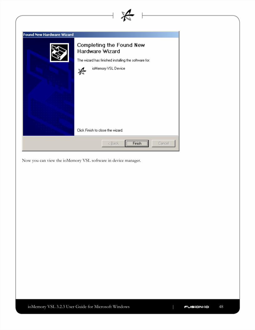
ioMemory VSL 3.2.3 User Guide for Microsoft Windows | __________________ ___ ___ 48
Now you can view the ioMemory VSL software in device manager.

ioMemory VSL 3.2.3 User Guide for Microsoft Windows | __________________ ___ ___ 49
1.
2.
If you need to update your firmware, review the and Outdated Firmware Check Upgrading the Device Firmware
sections of this guide.
Manual Install on Windows Server 2008 and 2012Before you manually install the ioMemory VSL software, make sure you have downloaded and run the ioMemory VSL
Windows Setup program . This will install the ioMemory VSL software on the from http://support.fusionio.com
system, and you will now be able to install the ioMemory VSL software for each ioMemory device.
The Windows Driver Wizard may automatically detect the new ioMemory device and starts to locate its ioMemory
VSL software after you restart the system. If this happens, you may skip to the Installation Wizard procedure below.
Launch the Device Manager.
In Windows Server 2008, choose > > .Start Control Panel Device Manager
In Windows Server 2012, from the select (in the upper right) > Server Manager Tools Computer
> .Management Device Manager
Select .Fusion ioMemory VSL devices
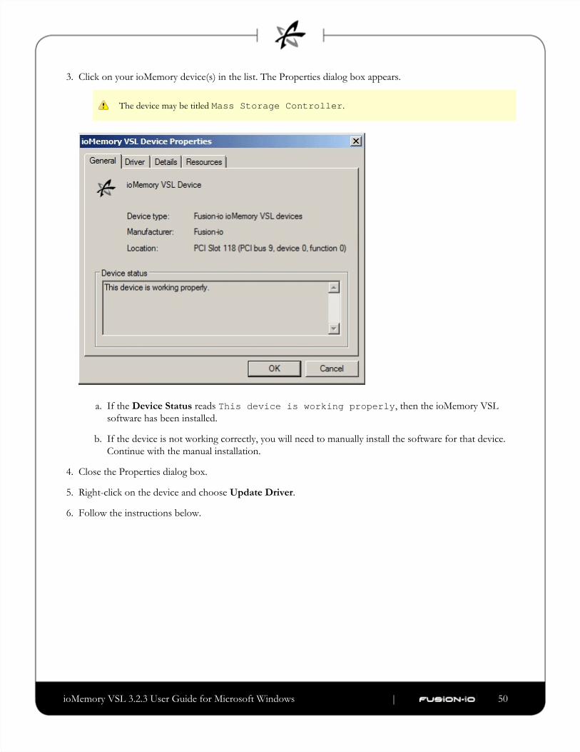
ioMemory VSL 3.2.3 User Guide for Microsoft Windows | __________________ ___ ___ 50
3.
a.
b.
4.
5.
6.
Click on your ioMemory device(s) in the list. The Properties dialog box appears.
The device may be titled .Mass Storage Controller
If the reads , then the ioMemory VSLDevice Status This device is working properlysoftware has been installed.
If the device is not working correctly, you will need to manually install the software for that device.
Continue with the manual installation.
Close the Properties dialog box.
Right-click on the device and choose .Update Driver
Follow the instructions below.
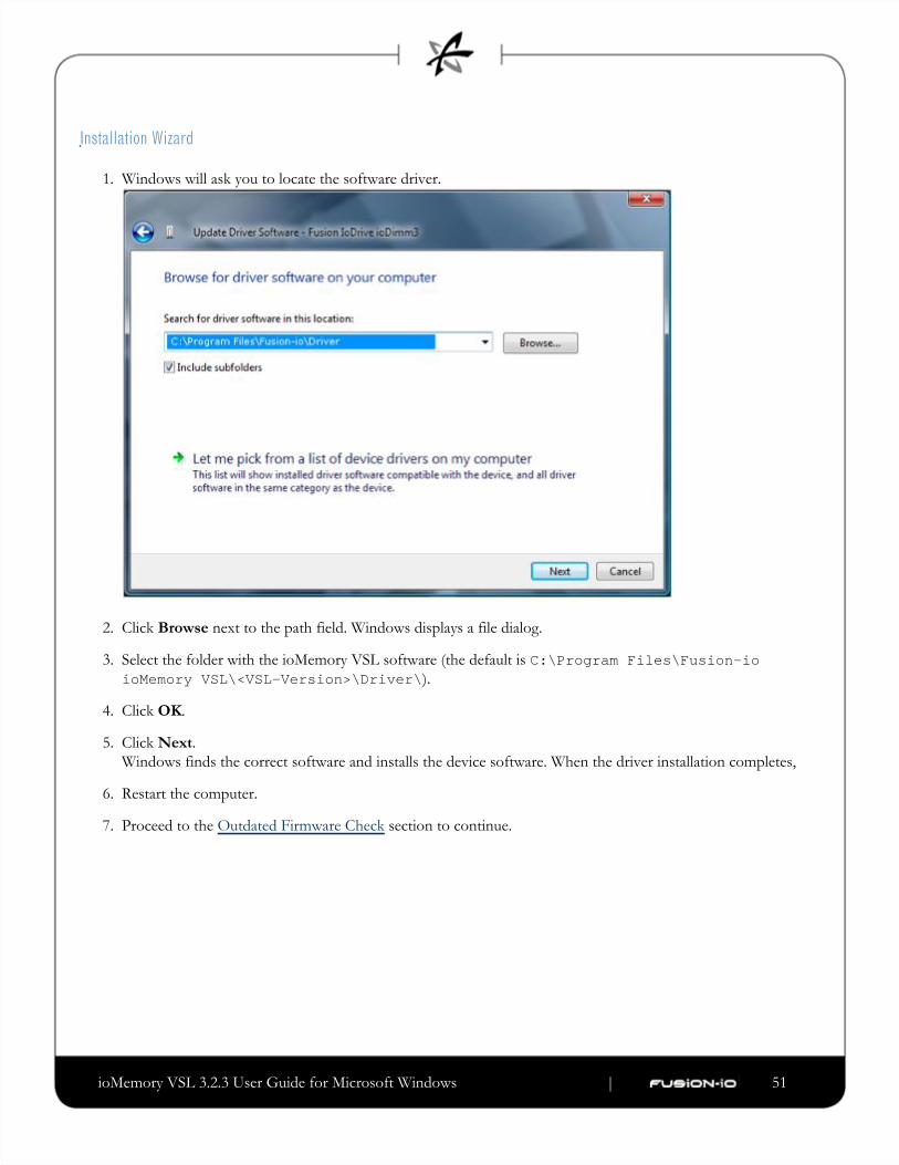
ioMemory VSL 3.2.3 User Guide for Microsoft Windows | __________________ ___ ___ 51
1.
2.
3.
4.
5.
6.
7.
Installation Wizard
Windows will ask you to locate the software driver.
Click next to the path field. Windows displays a file dialog.Browse
Select the folder with the ioMemory VSL software (the default is C:\Program Files\Fusion-io).ioMemory VSL\<VSL-Version>\Driver\
Click .OK
Click . Next
Windows finds the correct software and installs the device software. When the driver installation completes,
Restart the computer.
Proceed to the section to continue.Outdated Firmware Check

ioMemory VSL 3.2.3 User Guide for Microsoft Windows | __________________ ___ ___ 52
Appendix C- Command-line UtilitiesThe Windows Setup package installs various utilities into the C:\Program Files\Common Files\VSL Utilsfolder, described in the table below.
There are some additional utilities installed in the C:\Program Files\Common Files\VSL Utilsdirectory that are not listed below. Those additional utilities are dependencies (used by the main ioMemory VSL
utilities), and you should not use them directly unless Customer Support advises you to do so.
Utility Purpose
fio-attach Makes an ioMemory device available to the OS
fio-beacon Lights the ioMemory device's external LEDs
fio-bugreport Prepares a detailed report for use in troubleshooting problems
fio-config Enables configuration parameters for device operation
fio-detach Temporarily removes an ioMemory device from OS access
fio-format Used to perform a low-level format of an ioMemory device
fio-pci-check Checks for errors on the PCI bus tree, specifically for ioMemory device
fio-status Displays information about the device
fio-trim-config Enables or disables the TRIM feature
fio-update-iodrive Updates the ioMemory device's firmware
fio-sure-erase Clears or purges data from the device
Administrator Rights: The command-line utilities require administrator rights in order to run under Windows
(right-click the menu item and select .)Command Prompt Run as administrator
To run these utilities from a command line, you must either change to the directory which contains them (by
default, ) or add that directory to your system path.C:\Program Files\Common Files\VSL UtilsAs a convenience, if you used the Windows installer then the utilities directory has been added to the system path
for you. Otherwise, see the documentation for your version of Windows for information about adding a directory
to the system path.
ioMemory VSL 3.2.3 User Guide for Microsoft Windows | __________________ ___ ___ 53
There are (Help) and (Version) options for all of the utilities. Also, and cause the utility to exit after-h -v -h -vdisplaying the information.
fio-attachDescription
Attaches the ioMemory device and makes it available to Windows. You can then partition the ioMemory device, or set
it up as part of a RAID array, using the Windows Disk Management utility. This command displays a progress bar and
percentage as it completes the attach process.
In most cases, the ioMemory VSL software automatically attaches the device on load and does a scan. You only
need to run fio-attach if you ran fio-detach or if you set the ioMemory VSL software's auto_attach parameter to 0.
If the ioMemory device is in minimal mode, then auto-attach is disabled until the cause of the device being in
minimal mode is fixed.
Syntax
fio-attach <device> [options]
where is the name of the device node ( ), where indicates the device number: 0, 1, 2, etc. For<device> /dev/fctx x
example, indicates the first ioMemory device installed on the system./dev/fct0
You can specify multiple ioMemory devices. For example, indicates the second and third/dev/fct1 /dev/fct2ioMemory devices installed on the system.
Option Description
-r Force a metadata rescan. This may take an extended period of time, and is not normally required.
Only use this option when directed by Customer Support.
-c Attach only if clean.
-q Quiet: disables the display of the progress bar and percentage.
ioMemory VSL 3.2.3 User Guide for Microsoft Windows | __________________ ___ ___ 54
fio-beaconDescription
Lights the ioMemory device's three LEDs to locate the device. You should first detach the ioMemory device and then
run .fio-beacon
Syntax
fio-beacon <device> [options]
where is the name of the device node ( ), where indicates the card number: 0, 1, 2, etc. For<device> /dev/fctx x
example, indicates the first ioMemory device installed on the system. Use to view this/dev/fct0 fio-statusnumber.
Options Description
-0 Off: (Zero) Turns off the three LEDs
-1 On: Lights the three LEDs
-p Prints the PCI bus ID of the device at <device> to standard output. Usage and error information may be written to
standard output rather than to standard error.
fio-bugreportDescription
Prepares a detailed report of the device for use in troubleshooting problems.
Syntax
fio-bugreport
Notes
This utility captures the current state of the device. When a performance or stability problem occurs with the device,
run the utility and contact Customer Support for assistance infio-bugreport at [email protected]
troubleshooting.
fio-bugreport runs several information-gathering utilities and combines the resulting data into a text file. The
results are saved in the directory (default installation path is utils C:\Program Files\Common Files\VSL) in a file that indicates the date and time the utility was run.Utils .cab
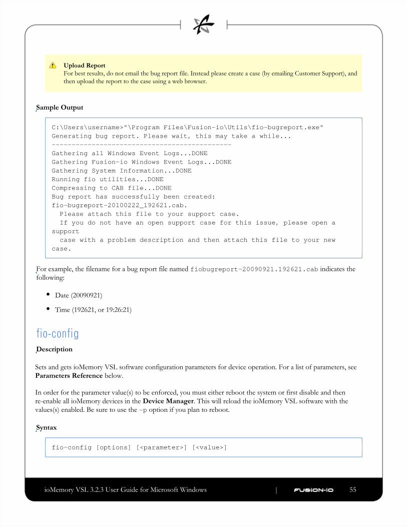
ioMemory VSL 3.2.3 User Guide for Microsoft Windows | __________________ ___ ___ 55
Upload Report
For best results, do not email the bug report file. Instead please create a case (by emailing Customer Support), and
then upload the report to the case using a web browser.
Sample Output
C:\Users\username>"\Program Files\Fusion-io\Utils\fio-bugreport.exe"Generating bug report. Please wait, this may take a while...---------------------------------------------Gathering all Windows Event Logs...DONEGathering Fusion-io Windows Event Logs...DONEGathering System Information...DONERunning fio utilities...DONECompressing to CAB file...DONEBug report has successfully been created:fio-bugreport-20100222_192621.cab. Please attach this file to your support case. If you do not have an open support case for this issue, please open asupport case with a problem description and then attach this file to your newcase.
For example, the filename for a bug report file named indicates thefiobugreport-20090921.192621.cabfollowing:
Date (20090921)
Time (192621, or 19:26:21)
fio-configDescription
Sets and gets ioMemory VSL software configuration parameters for device operation. For a list of parameters, see
below.Parameters Reference
In order for the parameter value(s) to be enforced, you must either reboot the system or first disable and then
re-enable all ioMemory devices in the . This will reload the ioMemory VSL software with theDevice Manager
values(s) enabled. Be sure to use the option if you plan to reboot.-p
Syntax
fio-config [options] [<parameter>] [<value>]
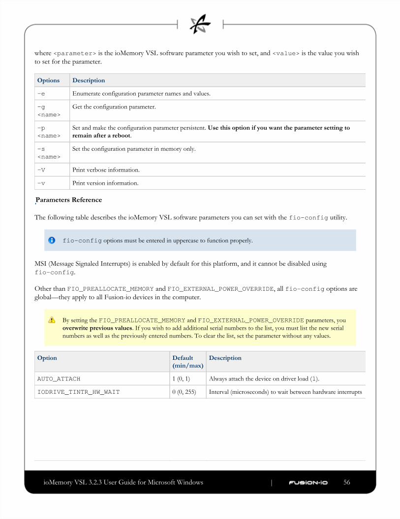
ioMemory VSL 3.2.3 User Guide for Microsoft Windows | __________________ ___ ___ 56
where is the ioMemory VSL software parameter you wish to set, and is the value you wish<parameter> <value>to set for the parameter.
Options Description
-e Enumerate configuration parameter names and values.
-g<name>
Get the configuration parameter.
-p<name>
Set and make the configuration parameter persistent. Use this option if you want the parameter setting to
.remain after a reboot
-s<name>
Set the configuration parameter in memory only.
-V Print verbose information.
-v Print version information.
Parameters Reference
The following table describes the ioMemory VSL software parameters you can set with the utility.fio-config
fio-config options must be entered in uppercase to function properly.
MSI (Message Signaled Interrupts) is enabled by default for this platform, and it cannot be disabled using
.fio-config
Other than and , all options areFIO_PREALLOCATE_MEMORY FIO_EXTERNAL_POWER_OVERRIDE fio-configglobal—they apply to all Fusion-io devices in the computer.
By setting the and parameters, you FIO_PREALLOCATE_MEMORY FIO_EXTERNAL_POWER_OVERRIDE. If you wish to add additional serial numbers to the list, you must list the new serialoverwrite previous values
numbers as well as the previously entered numbers. To clear the list, set the parameter without any values.
Option Default
(min/max)
Description
AUTO_ATTACH 1 (0, 1) Always attach the device on driver load ( ).1
IODRIVE_TINTR_HW_WAIT 0 (0, 255) Interval (microseconds) to wait between hardware interrupts

ioMemory VSL 3.2.3 User Guide for Microsoft Windows | __________________ ___ ___ 57
FIO_EXTERNAL_POWER_OVERRIDE No devices
selected
Allows selected devices to draw full power from the PCIe
slot. Where the for this parameter is a<value>comma-separated list of adapter serial numbers.
Use with care, see Enabling PCIe Power
for more information.Override
FORCE_MINIMAL_MODE 0 (0, 1) Force minimal mode on the device ( ), this parameter is set1to false ( ) by default.0
PARALLEL_ATTACH 0 (0, 1) Enable parallel attach of multiple devices ( ), this parameter1is set to false ( ) by default.0
FIO_PREALLOCATE_MEMORY 0 For the selected device, pre-allocate all memory necessary to
have the device usable as swap space. For example:
fio-config /dev/fct0 -pFIO_PREALLOCATE_MEMORY ="1234,54321"
where and are serial numbers"1234" "54321"obtained from .fio-status
WIN_LOG_VERBOSE ( / )0 0 1 If enabled ( ), the ioMemory VSL software will write1additional messages to the event log. This will assist
Customer Support in troubleshooting any device issues or
failures.
WIN_DISABLE_ALL_AFFINITY 0 (affinity is
enabled)
When is set to 0, theWIN_DISABLE_ALL_AFFINITYdriver will enable interrupt and worker thread affinity in the
driver. When is set to WIN_DISABLE_ALL_AFFINITY, the driver will disable all affinity settings. This is an1
override of any other affinity settings. The driver must be
reloaded for this parameter to take effect.
WIN_DISABLE_DEFAULT_NUMA_AFFINITY 0 ("default"
NUMA
affinity is
enabled)
When isWIN_DISABLE_DEFAULT_NUMA_AFFINITYset to , during initialization, the driver will query Windows0for the affinity settings assigned to the adapter by the OS.
This is what is known as the "default NUMA affinity". Once
the affinity is queried correctly, the driver sets the affinity of
the adapter's interrupt and associated worker threads to the
default OS setting. This generally has the effect of setting
the affinity of the interrupt and worker threads to all
processors on a single NUMA node in the system. When
is set to WIN_DISABLE_DEFAULT_NUMA_AFFINITY, the driver will ignore the affinity settings assigned to the1
adapter by the OS. The driver must be reloaded for this
parameter to take effect.

ioMemory VSL 3.2.3 User Guide for Microsoft Windows | __________________ ___ ___ 58
FIO_AFFINITY N/A FIO_AFFINITY is a list of <affinity triplets to specify the affinity settingsspecification>
of all adapters in the system. Each item in the triplet is
separated by a comma, and each triplet set is separated by a
semicolon.
For syntax information and examples
showing the use of this parameter, see
.Appendix G- NUMA Configuration
fio-detachDescription
Detaches the ioMemory device and removes the corresponding block device from the OS. The fctx fio-detachutility waits until the device completes all read/write activity before executing the detach operation. By default, the
command also displays a progress bar and percentage as it completes the detach.
Before using this utility, ensure that the device you want to detach is not currently mounted and in use.
Syntax
fio-detach <device> [options]
where is the name of the device node ( ), where indicates the device number: 0, 1, 2, etc. For<device> /dev/fctx x
example, indicates the first ioMemory device installed on the system./dev/fct0
You can specify multiple ioMemory devices. For example, indicates the second and third/dev/fct1 /dev/fct2ioMemory devices installed on the system.
Options Description
-f Force: Causes an immediate detach (does not save metadata).
Although the (force) option causes the ioMemory device to detach, even in a RAID setup, it is-fstrongly recommended to take the drives/volume offline using the Windows Disk Management
plug-in, then perform the detach. Forcing the detach may result in loss of data.
-q Quiet: Disables the display of the progress bar and percentage.
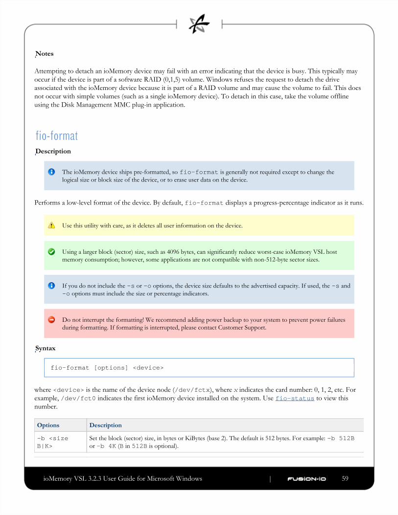
ioMemory VSL 3.2.3 User Guide for Microsoft Windows | __________________ ___ ___ 59
Notes
Attempting to detach an ioMemory device may fail with an error indicating that the device is busy. This typically may
occur if the device is part of a software RAID (0,1,5) volume. Windows refuses the request to detach the drive
associated with the ioMemory device because it is part of a RAID volume and may cause the volume to fail. This does
not occur with simple volumes (such as a single ioMemory device). To detach in this case, take the volume offline
using the Disk Management MMC plug-in application.
fio-formatDescription
The ioMemory device ships pre-formatted, so is generally not required except to change thefio-formatlogical size or block size of the device, or to erase user data on the device.
Performs a low-level format of the device. By default, displays a progress-percentage indicator as it runs.fio-format
Use this utility with care, as it deletes all user information on the device.
Using a larger block (sector) size, such as 4096 bytes, can significantly reduce worst-case ioMemory VSL host
memory consumption; however, some applications are not compatible with non-512-byte sector sizes.
If you do not include the or options, the device size defaults to the advertised capacity. If used, the and-s -o -s options must include the size or percentage indicators.-o
Do not interrupt the formatting! We recommend adding power backup to your system to prevent power failures
during formatting. If formatting is interrupted, please contact Customer Support.
Syntax
fio-format [options] <device>
where is the name of the device node ( ), where indicates the card number: 0, 1, 2, etc. For<device> /dev/fctx x
example, indicates the first ioMemory device installed on the system. Use to view this/dev/fct0 fio-statusnumber.
Options Description
-b <sizeB|K>
Set the block (sector) size, in bytes or KiBytes (base 2). The default is 512 bytes. For example: -b 512Bor ( in is optional).-b 4K B 512B
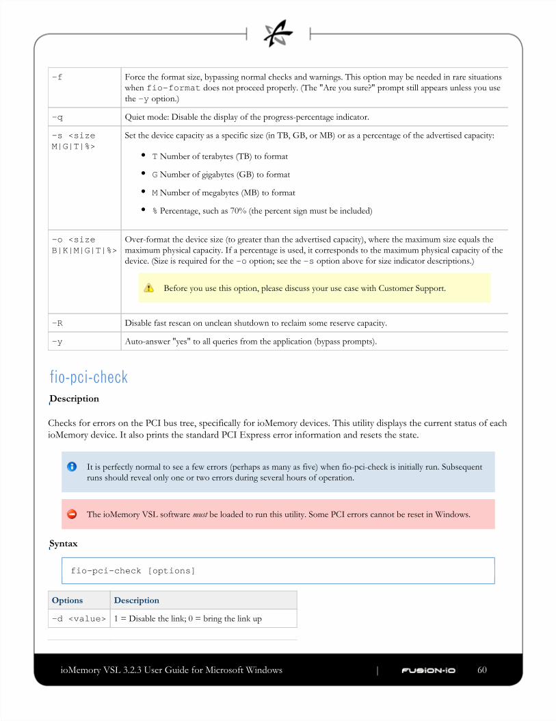
ioMemory VSL 3.2.3 User Guide for Microsoft Windows | __________________ ___ ___ 60
-f Force the format size, bypassing normal checks and warnings. This option may be needed in rare situations
when does not proceed properly. (The "Are you sure?" prompt still appears unless you usefio-formatthe option.)-y
-q Quiet mode: Disable the display of the progress-percentage indicator.
-s <sizeM|G|T|%>
Set the device capacity as a specific size (in TB, GB, or MB) or as a percentage of the advertised capacity:
T Number of terabytes (TB) to format
G Number of gigabytes (GB) to format
M Number of megabytes (MB) to format
% Percentage, such as 70% (the percent sign must be included)
-o <sizeB|K|M|G|T|%>
Over-format the device size (to greater than the advertised capacity), where the maximum size equals the
maximum physical capacity. If a percentage is used, it corresponds to the maximum physical capacity of the
device. (Size is required for the option; see the option above for size indicator descriptions.)-o -s
Before you use this option, please discuss your use case with Customer Support.
-R Disable fast rescan on unclean shutdown to reclaim some reserve capacity.
-y Auto-answer "yes" to all queries from the application (bypass prompts).
fio-pci-checkDescription
Checks for errors on the PCI bus tree, specifically for ioMemory devices. This utility displays the current status of each
ioMemory device. It also prints the standard PCI Express error information and resets the state.
It is perfectly normal to see a few errors (perhaps as many as five) when fio-pci-check is initially run. Subsequent
runs should reveal only one or two errors during several hours of operation.
The ioMemory VSL software be loaded to run this utility. Some PCI errors cannot be reset in Windows.must
Syntax
fio-pci-check [options]
Options Description
-d <value> 1 = Disable the link; 0 = bring the link up

ioMemory VSL 3.2.3 User Guide for Microsoft Windows | __________________ ___ ___ 61
-e Enable PCI-e error reporting.
-f Scan every device in the system.
-r Force the link to retrain.
-v Verbose: Print extra data about the hardware.
-y "Yes" is forced when the user is asked to continue.
fio-statusDescription
Provides detailed information about the installed devices. This utility operates on either or devices. Thefctx fioxutility depends on running as root and having the ioMemory VSL driver loaded. If no driver is loaded, a smaller set of
status information is returned.
fio-status provides alerts for certain error modes, such as a minimal-mode, read-only mode, and write-reduced
mode, describing what is causing the condition.
Syntax
fio-status [<device>] [<options>]
where is the name of the device node ( ), where indicates the card number: 0, 1, 2, etc. For<device> /dev/fctx x
example, indicates the first ioMemory device installed on the system./dev/fct0
If is not specified, displays information for all cards in the system. If the ioMemory VSL driver<dev> fio-statusis not loaded, this parameter is ignored.
Options Description
-a Report all available information for each device.
-e Show all errors and warnings for each device. This option is for diagnosing issues, and it hides other
information such as format sizes.
-c Count: Report only the number of ioMemory devices installed.
-d Show basic information set plus the total amount of data read and written (lifetime data volumes). This option is
not necessary when the -a option is used.
-fj Format JSON: creates the output in JSON format.
-fx Format XML: creates the output in XML format.
-u Show unavailable fields. Only valid with or .-fj -fx

ioMemory VSL 3.2.3 User Guide for Microsoft Windows | __________________ ___ ___ 62
-U Show unavailable fields and details why. Only valid with or .-fj -fx
Some fields are unavailable depending on the operating system or device. Forfio-statusexample, some legacy fields are unavailable on newer ioMemory devices.
-F<field> Print the value for a single field (see the next option for field names). Requires that a device be specified.
Multiple options may be specified.-F
-l List the fields that can be individually accessed with .-F
Output Change
The standard formatting of ouput has changed compared to the output from ioMemory VSLfio-statussoftware version 2.x. This will affect any custom management tools that used the output of this utility.
Basic Information: If no options are used, reports the following basic information:fio-status
Number and type of devices installed in the system
ioMemory VSL software version
Adapter information:
Adapter type
Product number
External power status
PCIe power limit threshold (if available)
Connected ioMemory devices
Block device information:
Attach status
Product name
Product number
Serial number
PCIe address and slot
Firmware version
Size of the device, out of total capacity
Internal temperature (average and maximum, since ioMemory VSL software load) in degrees Centigrade
Health status: healthy, nearing wearout, write-reduced or read-only
ioMemory VSL 3.2.3 User Guide for Microsoft Windows | __________________ ___ ___ 63
Reserve capacity (percentage)
Warning capacity threshold (percentage)
Data Volume Information: If the -d option is used, the following data volume information is reported toin addition
the basic information:
Physical bytes written
Physical bytes read
All Information: If the option is used, all information is printed, which includes the following information -a in
to basic and data volume information:addition
Adapter information:
Manufacturer number
Part number
Date of manufacture
Power loss protection status
PCIe bus voltage (avg, min, max)
PCIe bus current (avg, max)
PCIe bus power (avg, max)
PCIe power limit threshold (watts)
PCIe slot available power (watts)
PCIe negotiated link information (lanes and throughput)
Block device information:
Manufacturer's code
Manufacturing date
Vendor and sub-vendor information
Format status and sector information (if device is attached)
FPGA ID and Low-level format GUID
PCIe slot available power
PCIe negotiated link information
Card temperature, in degrees Centigrade
Internal voltage (avg and max)
ioMemory VSL 3.2.3 User Guide for Microsoft Windows | __________________ ___ ___ 64
1.
2.
Auxiliary voltage (avg and max)
Percentage of good blocks, data and metadata
Lifetime data volume statistics
RAM usage
Error Mode Information: If the ioMemory VSL software is in minimal mode, read-only mode, or write-reduced
mode when is run, the following differences occur in the output:fio-status
Attach status is "Status unknown: Driver is in MINIMAL MODE:"
The reason for the minimal mode state is displayed (such as "Firmware is out of date. Update firmware.")
"Geometry and capacity information not available." is displayed.
No media health information is displayed.
fio-sure-erase
As a best practice, do not use this utility if there are any ioMemory devices installed in the system that you do not
want to clear or purge. First remove any devices that you do not want to accidentally erase. Once the data is
removed with this utility it is gone forever. It is not recoverable.
Before you use this utility, be sure to back up any data that you wish to preserve.
After using , format the device using before using the device again.fio-sure-erase fio-format
If the device is in Read-only mode, perform a format using before running .fio-format fio-sure-eraseIf the device is in Minimal mode, then cannot erase the device. Updating the firmware mayfio-sure-erasetake the device out of Minimal Mode. If the device remains in Minimal mode, contact Customer Support at
. for further [email protected]
In order to run , the block device . See the section for morefio-sure-erase must be detached fio-detachinformation.
Description
The is a command-line utility that securely removes data from ioMemory devices. It complies withfio-sure-erasethe "Clear" and "Purge" level of destruction from the following standards:
DOD 5220.22-M – Comply with instructions for Flash EPROM
NIST SP800-88– Comply with instructions for Flash EPROM
ioMemory VSL 3.2.3 User Guide for Microsoft Windows | __________________ ___ ___ 65
1.
2.
3.
See below for more information on Clear and Purge support.
Registry Requirement
On Windows, a registry key must be created to configure the driver for ECC-bypass mode:
Locate the following key:
HKEY_LOCAL_MACHINE\SYSTEM\CurrentControlSet\Services\fiodrive\Parameters
Create a DWORD key underneath it called "BypassECC" and set the value to "1".
Restart the computer before running the utility.
Syntax
fio-sure-erase [options] <device>
where is the name of the device node ( ), where indicates the card number: 0, 1, 2, etc. For<device> /dev/fctx x
example, indicates the first ioMemory device installed on the system. Use to view this/dev/fct0 fio-statusnumber.
Products with Multiple Devices
fio-sure-erase works on individual ioMemory devices. For example, if you are planning to purge an
ioDrive Duo device, you will need to perform this operation on each of the product's two ioMemory devices.
Options Description
-p Purge instead of Clear: performs a write followed by an erase. For more information on Purge, see below.
Purging the device may take hours to accomplish, depending on the size of the device that needs to
be purged.
-t Do not preserve current format parameters, including device and sector size (reset to default).
-y No confirmation: do not require a yes/no response to execute the utility.
-q Quiet: do not display the status bar.
If you run with no options, a Clear is performed. For more information, see below.fio-sure-erase
Each block of memory consists of uniform 1 bits or 0 bits.
ioMemory VSL 3.2.3 User Guide for Microsoft Windows | __________________ ___ ___ 66
1.
2.
3.
4.
1.
2.
3.
4.
5.
Clear Support
A "Clear" is the default state of running (with no options), and refers to the act of performing afio-sure-erasefull low-level erase (every cell pushed to "1") of the entire NAND media, including retired erase blocks.
Metadata that is required for operation will not be destroyed (media event log, erase counts, physical bytes
read/written, performance and thermal history), but any user-specific metadata will be destroyed.
The following describes the steps taken in the Clear operation:
Creates a unity map of every addressable block (this allows to address every block,fio-sure-eraseincluding previously unmapped bad blocks).
For each block, performs an erase cycle (every cell is pushed to "1").
Restores the bad block map.
Formats the device (the purpose of this is to make the device usable again, the utility erases all of the headers
during the clear).
Purge Support
A "Purge" is implemented by using the option with . Purge refers to the act of first overwriting-p fio-sure-erasethe entire NAND media (including retired erase blocks) with a single character (every cell written to logical "0"), and
then performing a full chip erase (every cell pushed to "1") across all media (including retired erase blocks).
Metadata that is required for operation will be destroyed (media event log, erase counts, physical bytesnot
read/written, performance and thermal history), but any user-specific metadata will be destroyed.
The following describes the steps taken in the Purge operation:
Creates a unity map of every addressable block (this allows to address every block,fio-sure-eraseincluding previously unmapped bad blocks).
For each block, performs a write cycle (every cell written to "0").
For each block, performs an erase cycle (every cell pushed to "1").
Restores the bad block map.
Formats the drive (the purpose of this is to make the drive usable again, the utility erases all of the headers
during the clear).
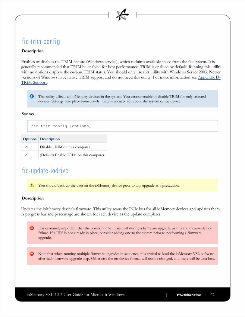
ioMemory VSL 3.2.3 User Guide for Microsoft Windows | __________________ ___ ___ 67
fio-trim-configDescription
Enables or disables the TRIM feature (Windows service), which reclaims available space from the file system. It is
generally recommended that TRIM be enabled for best performance. TRIM is enabled by default. Running this utility
with no options displays the current TRIM status. You should only use this utility with Windows Server 2003. Newer
versions of Windows have native TRIM support and do not need this utility. For more information see Appendix D-
.TRIM Support
This utility affects all ioMemory devices in the system. You cannot enable or disable TRIM for only selected
devices. Settings take place immediately, there is no need to reboot the system or the device.
Syntax
fio-trim-config [options]
Options Description
-d Disable TRIM on this computer.
-e (Default) Enable TRIM on this computer.
fio-update-iodrive
You should back up the data on the ioMemory device prior to any upgrade as a precaution.
Description
Updates the ioMemory device's firmware. This utility scans the PCIe bus for all ioMemory devices and updates them.
A progress bar and percentage are shown for each device as the update completes.
It is extremely important that the power not be turned off during a firmware upgrade, as this could cause device
failure. If a UPS is not already in place, consider adding one to the system prior to performing a firmware
upgrade.
Note that when running multiple firmware upgrades in sequence, it is critical to load the ioMemory VSL software
after each firmware upgrade step. Otherwise the on-device format will not be changed, and there will be data loss.
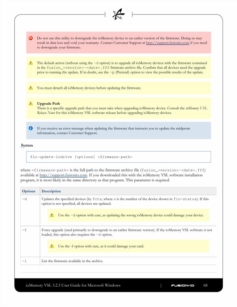
ioMemory VSL 3.2.3 User Guide for Microsoft Windows | __________________ ___ ___ 68
Do not use this utility to downgrade the ioMemory device to an earlier version of the firmware. Doing so may
result in data loss and void your warranty. Contact Customer Support if you need at http://support.fusionio.com
to downgrade your firmware.
The default action (without using the option) is to upgrade all ioMemory devices with the firmware contained-din the firmware archive file. Confirm that all devices need the upgradefusion_<version>-<date>.fffprior to running the update. If in doubt, use the (Pretend) option to view the possible results of the update.-p
You must detach all ioMemory devices before updating the firmware.
Upgrade Path
There is a specific upgrade path that you must take when upgrading ioMemory device. Consult the ioMemory VSL
for this ioMemory VSL software release before upgrading ioMemory devices.Release Notes
If you receive an error message when updating the firmware that instructs you to update the midprom
information, contact Customer Support.
Syntax
fio-update-iodrive [options] <firmware-path>
where is the full path to the firmware archive file<firmaware-path> ( )fusion_<version>-<date>.fff. If you downloaded this with the ioMemory VSL software installationavailable at http://support.fusionio.com
program, it is most likely in the same directory as that program. This parameter is required.
Options Description
-d Updates the specified devices (by , where is the number of the device shown in ). If thisfctx x fio-statusoption is not specified, all devices are updated.
Use the option with care, as updating the wrong ioMemory device could damage your device.-d
-f Force upgrade (used primarily to downgrade to an earlier firmware version). If the ioMemory VSL software is not
loaded, this option also requires the option.-d
Use the -f option with care, as it could damage your card.
-l List the firmware available in the archive.

ioMemory VSL 3.2.3 User Guide for Microsoft Windows | __________________ ___ ___ 69
-c Clears locks placed on a device.
-p Pretend: Shows what updates would be done. However, the actual firmware is not modified.
-q Runs the update process without displaying the progress bar or percentage.
-y Confirm all warning messages.
--split Split the ioMemory device into virtual devices.
--merge Merge the virtual devices of an ioMemory device.

ioMemory VSL 3.2.3 User Guide for Microsoft Windows | __________________ ___ ___ 70
Appendix D- TRIM Support
Introduction
TRIM is used to address a unique property of solid-state devices (SSD). The problem stems from the fact that when a
user deletes a file, the device that contains the file does not recognize that it can reclaim that space. Instead, the device
assumes the data is valid until the system informs the device it can overwrite that data. This is fine for a normal hard
device, because you can continually write to the same sector of the device without significant degradation. A solid-state
device, on the other hand, writes to different flash memory areas when the same logical sector is written to.
Because of the way flash memory handles writes, having a full SSD can cause significant reduction in write throughput.
Currently available storage stacks and file systems were not designed with this caveat in mind. The SSD software must
assume that all sectors contain valid data, and therefore always treat the device as full. In reality, a file system does not
normally contain a full device's worth of data.
TRIM is an enhancement to existing file systems that informs the SSD software of logical sectors that do not contain
valid user data. TRIM retrieves this information from a file system when a file has been deleted, and it informs the
device that it can reclaim the space held by that file. This allows the wear-leveling software to reclaim that space as
reserve to handle future write operations.
In order for TRIM to do this, it continually runs in the background and monitors the file system(s) being used on
Fusion-io devices. The process is meant to be "lazy" so as not to noticeably impact the performance of the computer.
PlatformsThe TRIM feature is available on ioMemory devices for Windows operating systems starting with Windows Server
2003.
TRIM capabilities have been built into Windows 7 and Windows Server 2008 R2 operating systems. ioMemory
devices support Windows 7 TRIM, which means that Fusion-io TRIM is unnecessary under Windows Server 2008
R2, and it will not run when this operating system is present. No system changes are needed. The Fusion-io TRIM
service will automatically shut off if it detects the Windows Server 2008 R2 operating system.
Using the TRIM ServiceTRIM runs quietly in the background as a Windows Service a few minutes after the computer is booted, so as not to
slow down the boot process. However, you can fine-tune TRIM by using the configurable settings described below.

ioMemory VSL 3.2.3 User Guide for Microsoft Windows | __________________ ___ ___ 71
1.
2.
1.
2.
3.
1.
Starting and Stopping TRIM
To start or stop the TRIM service through the Windows Services Manager,
Search for "Fusion-io Trim Service".
Click "Start service" or "Stop service".
Note that stopping the service only stops it for that session. Restarting the computer causes TRIM to run again.
Enabling TRIM
To enable the Fusion-io TRIM service,
Open a registry editor.
Navigate to
HKEY_LOCAL_MACHINE\SYSTEM\CurrentControlSet\Services\fiodrive\Parameters
Add the value as a (see the description below).Stop the TRIM service (by either of theTrimEnabled DWORDtwo previously mentioned methods) and restart it; or, restart the computer.
The utility will set the flag for you and does not require a reboot of yourfio-trim-config TrimEnabledsystem or a manual restart of the service for the changes to take effect. This utility is the preferred method of
enabling and disabling TRIM as it prevents the user from having to edit the registry themselves which has the
potential to produce undesired consequences.
TrimEnabled
This registry value controls whether TRIM will run, regardless of the user starting and stopping TRIM through either
of the two previously mentioned methods. If this value is present and set to 1, then TRIM will run as normal (unless
you have stopped the service using the previously mentioned methods). If this value is set to 0 before attempting to
start the Fusion-io TRIM service, the service will not run until the value is changed to 1 (or removed from the registry)
and the service manually restarted. If this value is not present, TRIM assumes it should run unless you stop it. Note
that this value persists across sessions, so if you restart the computer and set this value to 0, TRIM will not run when
the computer starts again.
Controlling TRIM Aggressiveness
You can control how aggressive the TRIM service is. The default settings for TRIM minimize impact on computer
performance while allowing the ioMemory device(s) to perform at their best. However, if a drive is being used with a
write-intensive application, then you may want TRIM to be more aggressive. To do this, you'll need to add a few
registry entries.
Open a registry editor.
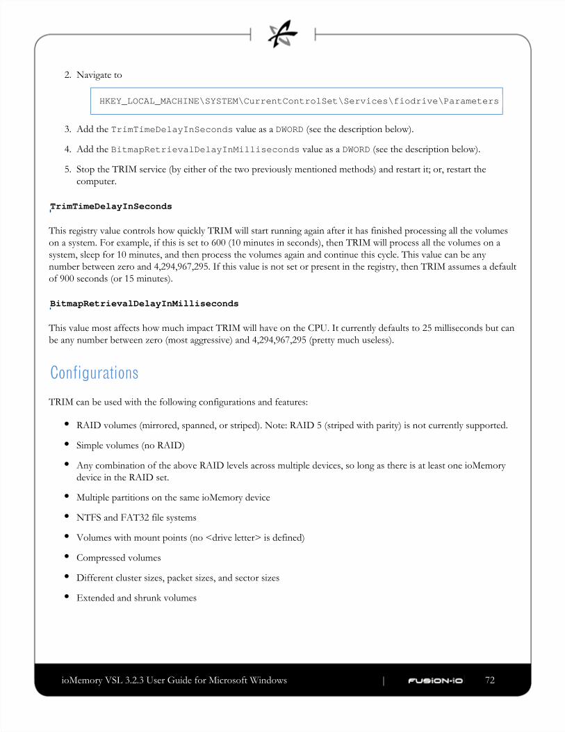
ioMemory VSL 3.2.3 User Guide for Microsoft Windows | __________________ ___ ___ 72
2.
3.
4.
5.
Navigate to
HKEY_LOCAL_MACHINE\SYSTEM\CurrentControlSet\Services\fiodrive\Parameters
Add the value as a (see the description below).TrimTimeDelayInSeconds DWORD
Add the value as a (see the description below).BitmapRetrievalDelayInMilliseconds DWORD
Stop the TRIM service (by either of the two previously mentioned methods) and restart it; or, restart the
computer.
TrimTimeDelayInSeconds
This registry value controls how quickly TRIM will start running again after it has finished processing all the volumes
on a system. For example, if this is set to 600 (10 minutes in seconds), then TRIM will process all the volumes on a
system, sleep for 10 minutes, and then process the volumes again and continue this cycle. This value can be any
number between zero and 4,294,967,295. If this value is not set or present in the registry, then TRIM assumes a default
of 900 seconds (or 15 minutes).
BitmapRetrievalDelayInMilliseconds
This value most affects how much impact TRIM will have on the CPU. It currently defaults to 25 milliseconds but can
be any number between zero (most aggressive) and 4,294,967,295 (pretty much useless).
ConfigurationsTRIM can be used with the following configurations and features:
RAID volumes (mirrored, spanned, or striped). Note: RAID 5 (striped with parity) is not currently supported.
Simple volumes (no RAID)
Any combination of the above RAID levels across multiple devices, so long as there is at least one ioMemory
device in the RAID set.
Multiple partitions on the same ioMemory device
NTFS and FAT32 file systems
Volumes with mount points (no <drive letter> is defined)
Compressed volumes
Different cluster sizes, packet sizes, and sector sizes
Extended and shrunk volumes

ioMemory VSL 3.2.3 User Guide for Microsoft Windows | __________________ ___ ___ 73
Appendix E- Monitoring the Health of ioMemoryDevices
This section describes how the health of ioMemory devices can be measured and monitored in order to safeguard data
and prolong device lifetime.
NAND Flash and Component FailureAn ioMemory device is a highly fault-tolerant storage subsystem that provides many levels of protection against
component failure and the loss nature of solid-state storage. As in all storage subsystems, component failures may
occur.
By properly selecting NAND flash media for the hosted application and proactively monitoring device age and health,
you can ensure reliable performance over the intended product life.
Health MetricsThe ioMemory VSL software manages block retirement using pre-determined retirement thresholds. The ioSphere
software and the utilities show a health indicator that starts at 100 and counts down to 0. As certainfio-statusthresholds are crossed, various actions are taken.
At the 10% healthy threshold, a one-time warning is issued. See the 'monitoring' section below for methods for
capturing this alarm event.
At 0%, the device is considered unhealthy. It enters mode, which somewhat prolongs its lifespan so datawrite-reduced
can be safely migrated off. In this state the ioMemory device behaves normally, except for the reduced write
performance.
After the 0% threshold, the device will soon enter mode – any attempt to write to the ioMemory device causesread-only
an error. Some filesystems may require special mount options in order to mount a read-only block device in addition
to specifying that the mount should be read-only.
Read-only mode should be considered a final opportunity to migrate data off the device, as device failure is more likely
with continued use.
The ioMemory device may enter failure mode. In this case, the device is offline and inaccessible. This can be caused by
an internal catastrophic failure, improper firmware upgrade procedures, or device wearout.
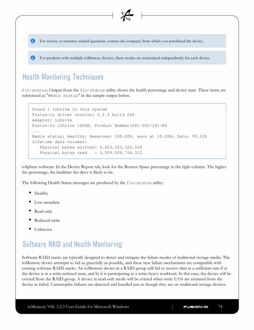
ioMemory VSL 3.2.3 User Guide for Microsoft Windows | __________________ ___ ___ 74
For service or warranty-related questions, contact the company from which you purchased the device.
For products with multiple ioMemory devices, these modes are maintained independently for each device.
Health Monitoring Techniquesfio-status: Output from the utility shows the health percentage and device state. These items arefio-statusreferenced as " " in the sample output below.Media status
Found 1 ioDrive in this systemFusion-io driver version: 2.2.3 build 240Adapter: ioDriveFusion-io ioDrive 160GB, Product Number:FS1-002-161-ES...Media status: Healthy; Reserves: 100.00%, warn at 10.00%; Data: 99.12%Lifetime data volumes: Physical bytes written: 6,423,563,326,064 Physical bytes read : 5,509,006,756,312
ioSphere software: In the Device Report tab, look for the Reserve Space percentage in the right column. The higher
the percentage, the healthier the drive is likely to be.
The following Health Status messages are produced by the utility:fio-status
Healthy
Low metadata
Read-only
Reduced-write
Unknown
Software RAID and Health MonitoringSoftware RAID stacks are typically designed to detect and mitigate the failure modes of traditional storage media. The
ioMemory device attempts to fail as gracefully as possible, and these new failure mechanisms are compatible with
existing software RAID stacks. An ioMemory device in a RAID group will fail to receive data at a sufficient rate if a)
the device is in a write-reduced state, and b) it is participating in a write-heavy workload. In this case, the device will be
evicted from the RAID group. A device in read-only mode will be evicted when write I/Os are returned from the
device as failed. Catastrophic failures are detected and handled just as though they are on traditional storage devices.
ioMemory VSL 3.2.3 User Guide for Microsoft Windows | __________________ ___ ___ 75
Appendix F- Using Windows Page Files with theioMemory Devices
Introduction
This appendix describes how to effectively use paging (swap) files on ioMemory devices with Windows.
Using a page file with a traditional disk drive places practical limits on the usable size of the page file and virtual
memory, due to the poor performance of disk drives in relation to RAM. Placing the OS paging file on one or more
ioMemory devices allows much larger page files and usable virtual memory. This is due to the much faster response
times and bandwidth on ioMemory devices versus hard disks.
Configuring Device Paging SupportThe ioMemory VSL software can be configured to support paging files on one or more ioMemory devices. This
requires that each ioMemory device used with a paging file pre-allocates the worst-case amount of memory it may need
in any possible I/O scenario. This is done on a per-adapter (ioDIMM) instance.
Because of the extra host RAM memory use, paging should be enabled only on ioMemory devices that will actually
hold a paging file. It is possible to place a single paging file on more than one ioMemory device. In this case Windows
will stripe paging I/O across all available paging files, possibly providing additional performance to the Virtual
Memory (VM) subsystem.
ioMemory VSL RAM Consumption
The amount of RAM pre-allocated per ioMemory device depends on the device's total size and the sector (block) size
selected when formatting the drive (with ).fio-format
Consult the Release Notes for this version of the software for RAM usage per GB of ioMemory device.
Using a larger sector size significantly reduces the amount of host memory consumption needed for paging support. It
is recommended that a 4K sector size be used because a) that is generally the natural size of a host memory page, and
b) it minimizes overall host memory consumption. In Windows, NTFS will generally use a cluster size of 4K, so
formatting to 512 is not useful except for applications that compatible only with 512-byte sector sizes.
The indicated amount is needed per ioMemory device that supports paging. You must carefully plan which ioMemory

ioMemory VSL 3.2.3 User Guide for Microsoft Windows | __________________ ___ ___ 76
device(s) will be used to hold a paging file.
Non-paged Memory Pool
Pre-allocated memory for the ioMemory device comes from the Windows kernel non-paged memory pool. This pool
dynamically grows as system components consume additional kernel memory. The maximum size of this pool is
restricted to 75% of RAM up to a maximum of 128GB.
The amount of in-use, non-paged pool memory should be noted when planning page file usage. This is because the
ioMemory device pre-allocates RAM, and that reduces the available physical non-paged memory. The ioMemory VSL
software will fail to load if the total pre-allocated memory plus the in-use, non-paged memory exceeds the maximum
non-paged memory pool.
To determine the total non-paged memory pool use for two ioMemory devices, let's use the following example:
One ioMemory device that requires 850 MB of RAM, and the other requires 1700 MB or RAM.
Consult the for this version of the ioMemory VSL software for RAMioMemory VSL Release Notes
requirements.
Both are formatted with a 4K sector size
Both will support paging files
The current allocated non-paged pool is obtained from Task Manager and, in this example, has a value of 576 MiB.
(Values shown in Task Manager are in MiB [1024x1024 = 1 MiB]). The total RAM on the system is 8000 MB and the
OS is Server 2008 R2.
First, covert the 576 MiB into MB: 576 MiB * (1 MB/1.048576 MiB) = ~549 MB
To calculate the total available non-paged pool, use the following formula:
(8000 MB x 0.75) - 549 - 850 - 1700
which still leaves 2901 MB available for the non-paged pool.
Enabling/Disabling Paging Support
Memory pre-allocation occurs during ioMemory VSL software initialization. To enable paging support, you must
enable the configuration item. This can be done using the FIO_PREALLOCATE_MEMORY fio-configcommand-line utility. This parameter is assigned a string with a list of decimal serial numbers of the ioMemory devices
that will support a paging file. The ioMemory VSL software performs memory pre-allocation for those instances.
Below is an example of using the utility to enable paging and pre-allocation on two ioMemory devicesfio-configwith serial numbers 1234 and 17834. Serial number information can be obtained using the utility.fio-status

ioMemory VSL 3.2.3 User Guide for Microsoft Windows | __________________ ___ ___ 77
1.
2.
3.
fio-config -p FIO_PREALLOCATE_MEMORY "1234,17834"
To disable paging support on all devices, use a value of for :0 FIO_PREALLOCATE_MEMORY
fio-config -p FIO_PREALLOCATE_MEMORY "0"
To query the current value, run this command:
fio-config -g FIO_PREALLOCATE_MEMORY
An alternate method to manage (enable or disable) paging support is to use the ioSphere software.
You must reload the ioMemory VSL software for the new pre-allocation setting to take effect. Typically this can
be done by restarting the machine or using disable/enable within Device Manager for each ioMemory device
instance.
Also, using the Windows System Properties to change paging file configuration requires a system restart before
the properties are applied. Therefore, you can change both FIO_PREALLOCATE_MEMORY and the system
page file configuration and then apply both with a single restart.
Windows Page File ManagementBy default, the ioMemory VSL software disables support for page files. The previous section described how to enable
support for page files on one or more ioMemory devices. The following describes how to work with the built-in
Windows control panels to configure and set up paging files on ioMemory devices.
Setting Up Paging File(s)
To set up page files in Windows,
Go to and double-click System.Control Panel
Click from the Task pane.Advanced system settings
On the Advanced tab, click . The Performance Options dialog opens.Settings
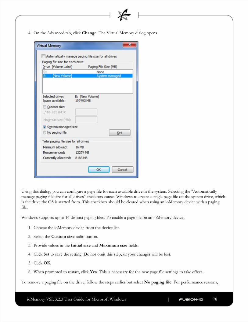
ioMemory VSL 3.2.3 User Guide for Microsoft Windows | __________________ ___ ___ 78
4.
1.
2.
3.
4.
5.
6.
On the Advanced tab, click . The Virtual Memory dialog opens. Change
Using this dialog, you can configure a page file for each available drive in the system. Selecting the "Automatically
manage paging file size for all drives" checkbox causes Windows to create a single page file on the system drive, which
is the drive the OS is started from. This checkbox should be cleared when using an ioMemory device with a paging
file.
Windows supports up to 16 distinct paging files. To enable a page file on an ioMemory device,
Choose the ioMemory device from the device list.
Select the radio button.Custom size
Provide values in the and fields.Initial size Maximum size
Click to save the setting. Do not omit this step, or your changes will be lost.Set
Click .OK
When prompted to restart, click . This is necessary for the new page file settings to take effect.Yes
To remove a paging file on the drive, follow the steps earlier but select . For performance reasons,No paging file

ioMemory VSL 3.2.3 User Guide for Microsoft Windows | __________________ ___ ___ 79
1.
2.
3.
1.
2.
typically you will remove all paging files on any system hard disk.
The Virtual Memory dialog allows page files to be configured on available ioMemory devices, even if the
ioMemory device has not been configured to support a page file. Even though the dialog allows enabling of the
page file, following the required restart you'll notice that no page file was created on the device. Follow the
directions earlier in this document to properly enable page file support on one or more ioMemory devices.
System Drive Paging File Configuration
By default Windows creates and manages a page file on the system boot drive (typically a hard disk), which is typically
where Windows is installed. Keeping a regular page file on the system hard disk is generally not optimal, because the
hard disk's I/O performance is many orders of magnitude slower than an ioMemory device. To remedy this, you can
eliminate or minimize the size of the system boot drive page file, as explained later. Enabling page files on ioMemory
devices (but not the system drive) improves Virtual Memory (VM) subsystem performance, as the VM manager stripes
I/O across all available page files. Additionally, the ioMemory devices act as a very large memory store, which can
greatly improve memory usage for large applications.
The Windows kernel uses the system disk page file to store crash dumps. Crash dumps may be small (mini-dumps) or
large (full-kernel memory dumps). Typically, running without dump file support or with a small dump file is adequate.
There are several possible system drive page file configurations:
Eliminate all page files on any hard disks, including the system boot drive. Although this maximizes paging I/O
on ioMemory devices, no post-mortem crash dump file will be available if a system crash occurs. However, it
may be possible to re-enable a page file on the system drive and then reproduce the crash scenario.
Create a minimal-size page file on the system boot drive. The recommended minimum size is 16MB, although
Windows may warn that a minimum 400MB page file is needed.
Create a page file large enough for a full-kernel memory dump. This typically requires a page file at least the size
of installed RAM, with some recommending the size equal to RAM x 1.5.
Fusion-io is actively working on adding support for an ioMemory device being a crash dump target.
To view or change the crash dump configuration,
Go to the dialog.System Properties
Click the Advanced tab.
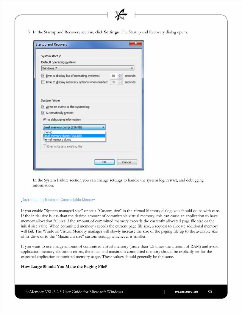
ioMemory VSL 3.2.3 User Guide for Microsoft Windows | __________________ ___ ___ 80
3. In the Startup and Recovery section, click . The Startup and Recovery dialog opens. Settings
In the System Failure section you can change settings to handle the system log, restart, and debugging
information.
Guaranteeing Minimum Committable Memory
If you enable "System managed size" or set a "Custom size" in the Virtual Memory dialog, you should do so with care.
If the initial size is less than the desired amount of committable virtual memory, this can cause an application to have
memory allocation failures if the amount of committed memory exceeds the currently allocated page file size or the
initial size value. When committed memory exceeds the current page file size, a request to allocate additional memory
will fail. The Windows Virtual Memory manager will slowly increase the size of the paging file up to the available size
of its drive or to the "Maximum size" custom setting, whichever is smaller.
If you want to use a large amount of committed virtual memory (more than 1.5 times the amount of RAM) and avoid
application memory allocation errors, the initial and maximum committed memory should be explicitly set for the
expected application committed memory usage. These values should generally be the same.
How Large Should You Make the Paging File?
ioMemory VSL 3.2.3 User Guide for Microsoft Windows | __________________ ___ ___ 81
The following articles explain in great detail how to size the page file appropriately.
Main Article Link: Pushing the Limits of Windows
Specific section that documents virtual memory: Pushing the Limits of Windows: Virtual Memory
Verifying Page File Operation
To verify that a page file is actively placed on an ioMemory device, you can browse for hidden files at the drive's root.
For example, run the following command at a prompt:
dir c: /ah
In the output listing there should be a file called . If no page file is present, then recheck the page filepagefile.sysconfiguration in the Virtual Memory dialog and verify that page file support has been enabled on the queried
ioMemory device.
PerformanceUsing the ioMemory device as the paging store can improve overall Virtual Memory system performance. Actual
benefits will vary widely with an application's virtual memory usage and with hardware platform/performance.
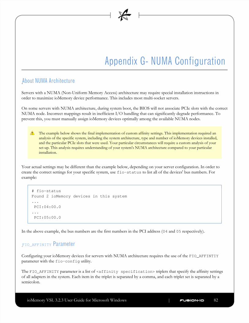
ioMemory VSL 3.2.3 User Guide for Microsoft Windows | __________________ ___ ___ 82
Appendix G- NUMA Configuration
About NUMA Architecture
Servers with a NUMA (Non-Uniform Memory Access) architecture may require special installation instructions in
order to maximize ioMemory device performance. This includes most multi-socket servers.
On some servers with NUMA architecture, during system boot, the BIOS will not associate PCIe slots with the correct
NUMA node. Incorrect mappings result in inefficient I/O handling that can significantly degrade performance. To
prevent this, you must manually assign ioMemory devices optimally among the available NUMA nodes.
The example below shows the final implementation of custom affinity settings. This implementation required an
analysis of the specific system, including the system architecture, type and number of ioMemory devices installed,
and the particular PCIe slots that were used. Your particular circumstances will require a custom analysis of your
set-up. This analysis requires understanding of your system's NUMA architecture compared to your particular
installation.
Your actual settings may be different than the example below, depending on your server configuration. In order to
create the correct settings for your specific system, use to list all of the devices' bus numbers. Forfio-statusexample:
# fio-statusFound 2 ioMemory devices in this system... PCI:04:00.0... PCI:05:00.0
In the above example, the bus numbers are the first numbers in the PCI address ( and respectively).04 05
FIO_AFFINITY Parameter
Configuring your ioMemory devices for servers with NUMA architecture requires the use of the FIO_AFFINTIYparameter with the utility.fio-config
The parameter is a list of triplets that specify the affinity settingsFIO_AFFINITY <affinity specification>of all adapters in the system. Each item in the triplet is separated by a comma, and each triplet set is separated by a
semicolon.

ioMemory VSL 3.2.3 User Guide for Microsoft Windows | __________________ ___ ___ 83
Syntax:
fio-config -p FIO_AFFINITY <affinity specification>[;<affinityspecification>...]
Where each has the following syntax:<affinity specification>
<[domain number:]bus number>,[g|n]<group or node number>[,<hex mask>]
If domain number is not specified, it will be set to 0 (most common).
If there is no or character before the group/node number, then the number is assumed to be a group number.g n
The hex mask is optional. If it is not present, the mask is assumed to be . Also, the prefix0xffffffffffffffff 0xis optional.
If the hex mask is a node mask, then the mask is relative to the node, not the group to which the node belongs.
Simple Example:
fio-config -p FIO_AFFINITY 1:7,n0,0xf;20,n1;80,7;2:132,4,0xff0
Has the effect of creating :
PCI Address ( )domain:bus Node/Group Processor Affinity
1:7 node 0 processors 0 to 3 in the node (mask )0xf
0:20 node 1 all processors in the node (no hex mask)
0:80 group 7 all processors in the group (no hex mask)
2:132 group 4 processors 4 to 11 in the group (mask )0xff0
Advanced Configuration Example
If your server has multiple NUMA nodes and multiple ioMemory devices installed, you will need to make sure that the
ioMemory devices are spread out among the various nodes.
While it may be optimal to pair devices to nodes that are electronically closer each device's PCIe slot (which would
require an advanced understanding of your server's NUMA architechure and an analysis of the device installation), just
simply spreading out all of the devices' node affinity among the available nodes should result in improved
performance.
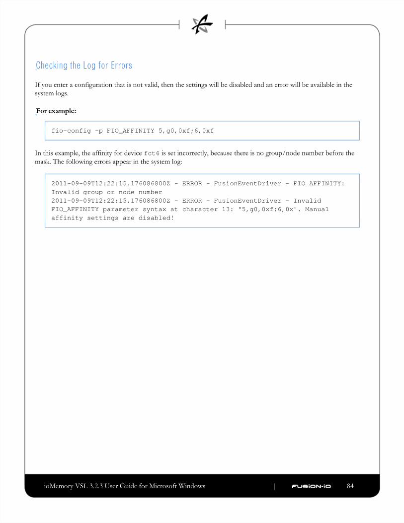
ioMemory VSL 3.2.3 User Guide for Microsoft Windows | __________________ ___ ___ 84
Checking the Log for Errors
If you enter a configuration that is not valid, then the settings will be disabled and an error will be available in the
system logs.
For example:
fio-config -p FIO_AFFINITY 5,g0,0xf;6,0xf
In this example, the affinity for device is set incorrectly, because there is no group/node number before thefct6mask. The following errors appear in the system log:
2011-09-09T12:22:15.176086800Z - ERROR - FusionEventDriver - FIO_AFFINITY:Invalid group or node number2011-09-09T12:22:15.176086800Z - ERROR - FusionEventDriver - InvalidFIO_AFFINITY parameter syntax at character 13: "5,g0,0xf;6,0x". Manualaffinity settings are disabled!

ioMemory VSL 3.2.3 User Guide for Microsoft Windows | __________________ ___ ___ 85
Appendix H- Upgrading Devices from VSL 2.x to 3.xThis version of the ioMemory VSL software supports new features, including the latest generation of ioMemory
architecture and improved Flashback protection. These features require the latest version of the Fusion-io firmware.
Every ioMemory device in a system running 3.1.x or later must be upgraded to the latest version of the firmware.
For example, if you have a system running 2.x ioMemory VSL software with ioDrive devices previously installed, and
you want to install new ioDrive2 devices (that require the latest version of the firmware), then you will need to upgrade
all of the existing devices to the latest firmware version.
You cannot revert a device's firmware to an earlier version once you have upgraded the device (without voiding
your warranty). If you experience problems with your upgrade, please contact Customer Support at
Upgrading devices (previously configured for VSL 2.x.x) to work with VSL 3.x.x will require a low-level media
format of the device. No user data will be maintained during the process. Be sure to backup all data as instructed.
Upgrade Path
Depending on the current firmware version of your devices, you may need to upgrade your device's firmware
multiple times in order to preserve internal structures. Consult the ioMemory VSL software for the upgrade path.
Visit for all of the required software and firmware versions.http://support.fusionio.com
For more information on upgrading from one version to the next, see the (available at ioMemory VSL Release Notes
) for the version you will upgrade the device to. Then follow the upgrade instructions inhttp://support.fusionio.com
that version's user guide for your operating system (including the firmware update instructions).
Upgrade ProcedureBe sure to follow the upgrade path in the . Make sure that all previously installed ioDriveioMemory VSL Release Notes
devices are updated with the appropriate firmware.
If you plan to use ioDrive devices and ioDrive2 devices in the same host, perform this upgrade on all existing
ioDrive devices installing the new ioDrive2 devices.before
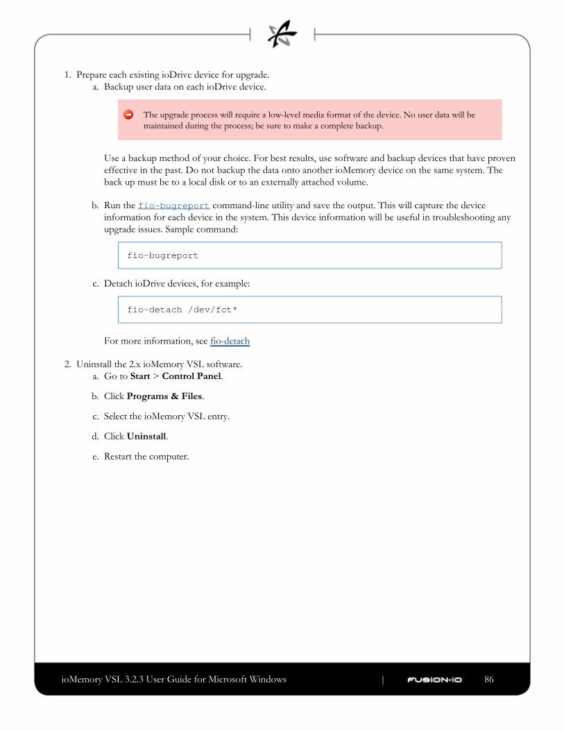
ioMemory VSL 3.2.3 User Guide for Microsoft Windows | __________________ ___ ___ 86
1.
a.
b.
c.
2.
a.
b.
c.
d.
e.
Prepare each existing ioDrive device for upgrade.
Backup user data on each ioDrive device.
The upgrade process will require a low-level media format of the device. No user data will be
maintained during the process; be sure to make a complete backup.
Use a backup method of your choice. For best results, use software and backup devices that have proven
effective in the past. Do not backup the data onto another ioMemory device on the same system. The
back up must be to a local disk or to an externally attached volume.
Run the command-line utility and save the output. This will capture the devicefio-bugreportinformation for each device in the system. This device information will be useful in troubleshooting any
upgrade issues. Sample command:
fio-bugreport
Detach ioDrive devices, for example:
fio-detach /dev/fct*
For more information, see fio-detach
Uninstall the 2.x ioMemory VSL software.
Go to > .Start Control Panel
Click .Programs & Files
Select the ioMemory VSL entry.
Click .Uninstall
Restart the computer.
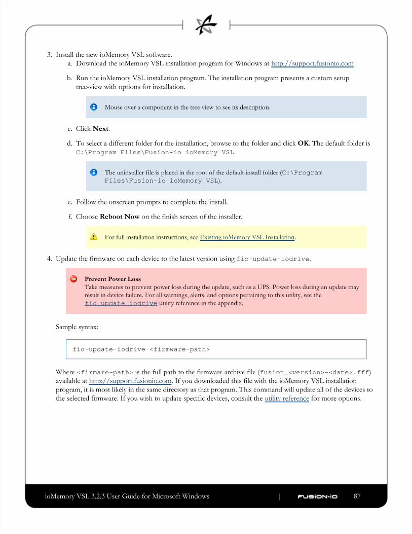
ioMemory VSL 3.2.3 User Guide for Microsoft Windows | __________________ ___ ___ 87
3.
a.
b.
c.
d.
e.
f.
4.
Install the new ioMemory VSL software.
Download the ioMemory VSL installation program for Windows at http://support.fusionio.com
Run the ioMemory VSL installation program. The installation program presents a custom setup
tree-view with options for installation.
Mouse over a component in the tree view to see its description.
Click .Next
To select a different folder for the installation, browse to the folder and click . The default folder is OK
.C:\Program Files\Fusion-io ioMemory VSL
The uninstaller file is placed in the root of the default install folder (C:\Program).Files\Fusion-io ioMemory VSL
Follow the onscreen prompts to complete the install.
Choose on the finish screen of the installer.Reboot Now
For full installation instructions, see .Existing ioMemory VSL Installation
Update the firmware on each device to the latest version using .fio-update-iodrive
Prevent Power Loss
Take measures to prevent power loss during the update, such as a UPS. Power loss during an update may
result in device failure. For all warnings, alerts, and options pertaining to this utility, see the
utility reference in the appendix.fio-update-iodrive
Sample syntax:
fio-update-iodrive <firmware-path>
Where is the full path to the firmware archive file <firmare-path> ( )fusion_<version>-<date>.fffavailable at . If you downloaded this file with the ioMemory VSL installationhttp://support.fusionio.com
program, it is most likely in the same directory as that program. This command will update all of the devices to
the selected firmware. If you wish to update specific devices, consult the for more options.utility reference
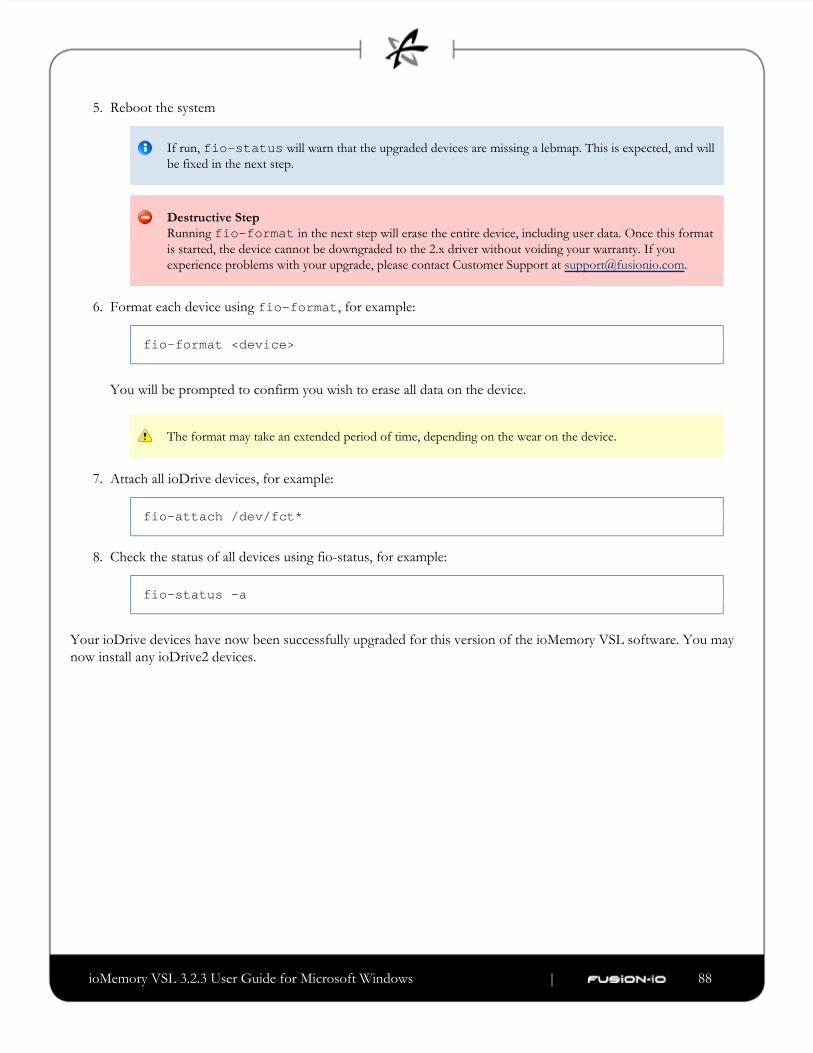
ioMemory VSL 3.2.3 User Guide for Microsoft Windows | __________________ ___ ___ 88
5.
6.
7.
8.
Reboot the system
If run, will warn that the upgraded devices are missing a lebmap. This is expected, and willfio-statusbe fixed in the next step.
Destructive Step
Running in the next step will erase the entire device, including user data. Once this formatfio-formatis started, the device cannot be downgraded to the 2.x driver without voiding your warranty. If you
experience problems with your upgrade, please contact Customer Support at [email protected]
Format each device using , for example:fio-format
fio-format <device>
You will be prompted to confirm you wish to erase all data on the device.
The format may take an extended period of time, depending on the wear on the device.
Attach all ioDrive devices, for example:
fio-attach /dev/fct*
Check the status of all devices using fio-status, for example:
fio-status -a
Your ioDrive devices have now been successfully upgraded for this version of the ioMemory VSL software. You may
now install any ioDrive2 devices.
ioMemory VSL 3.2.3 User Guide for Microsoft Windows | __________________ ___ ___ 89
Fusion Powered SupportWe offer Fusion-io Customer Services and Support by phone, e-mail and on the Web. For the most up-to-date contact
information visit .http://support.fusionio.com
Our support e-mail address is: [email protected]
E-mail is the fastest way to get simple questions answered. Please give a detailed description of your problem with your
complete contact information (name, phone number, email address, location address).
Warranty Support
Warranty Support is available via and [email protected] http://support.fusionio.com
Telephone Support
ioFX Support
North America: (855) 322-5767
Enterprise Support
North America: (877) 816-5740
Country Numbers
For product support outside of North America, please use the number for the country/region closest to you. If that is
not possible, please contact North America at (801) 424 5474.
Australia
(02) 8278 1489
Belgium
02 700 74 86
China
40-08866109
Denmark
4331 4999
Finland
097 251 9979
France
01 57 32 48 90
Germany
(069) 17 07 76 790
Hong Kong
3071 3587
Italy
02 23331509
Japan
(03) 6743-9765
Luxembourg
(224) 87 19 84
Mexico
01 882 816 5740
Netherlands
070 7703993
Norway
23 02 49 99
Singapore
6818 5692
South Korea
02 3483 6689
Sweden
08 593 663 99
United Kingdom
(020) 3564 9935

ioMemory VSL 3.2.3 User Guide for Microsoft Windows | __________________ ___ ___ 90
Web
Go online to find tips, FAQs, and troubleshooting help, or download the latest user guides, software, and support
packages at: .http://support.fusionio.com
ioMemory VSL 3.1.5 User Guide for Microsoft Windows ___________________________
Fusion Powered SupportWe offer ioDrive Customer Support by phone, e-mail and on the Web.
Please use the contact form at:http://support.ts.fujitsu.com/contact/ For the Japanese market, please use the following URL: http://primeserver.fujitsu.com/primergy/support/ Telephone Support
For customer support phone numbers, please refer to the Fujitsu TechnologySolutions service desk at http://ts.fujitsu.com/support/servicedesk.html For the Japanese market, please use the following URL: http://primeserver.fujitsu.com/primergy/support/supportdesk.html
Web
It is recommended to use the latest firmware / driver / BIOS versions on servers and components. Software packages are available for download at : http://support.ts.fujitsu.com > Server > Drivers & Downloads For the Japanese market, please use the following URL: http://primeserver.fujitsu.com/primergy/downloads Corresponding user documentation for servers and optional components can be found online athttp://manuals.ts.fujitsu.com > Industry Standard Servers > Expansion Cards > PCIe SSD Cardsor on the ServerView Suite Documentation DVD. For the Japanese market, please use the following URL: http://primeserver.fujitsu.com/primergy/manual.html