ion mobility spectrometer / mass spectrometer...
TRANSCRIPT

SANDIA REPORTSAND2005-63606360
Printed October 2005
Ion Mobility Spectrometer Mass Spectrometer (IMS-MS)
Austin Daniel E Hunka Deborah
Prepared by Sandia National LaboratoriesAlbuquerque New Mexico 87185 and Livermore California 94550
Sandia is a multiprogram laboratory operated by Sandia Corporationa Lockheed Martin Company for the United States Department of EnergyrsquosNational Nuclear Security Administration under Contract DE-AC04-94AL85000
2
Issued by Sandia National Laboratories operated for the United States Department of Energy by Sandia Corporation
NOTICE This report was prepared as an account of work sponsored by an agency of the United States Government Neither the United States Government nor any agency thereof nor any of their employees nor any of their contractors subcontractors or their employees make any warranty express or implied or assume any legal liability or responsibility for the accuracy completeness or usefulness of any information apparatus product or process disclosed or represent that its use would not infringe privately owned rights Reference herein to any specific commercial product process or service by trade name trademark manufacturer or otherwise does not necessarily constitute or imply its endorsement recommendation or favoring by the United States Government any agency thereof or any of their contractors or subcontractors The views and opinions expressed herein do not necessarily state or reflect those of the United States Government any agency thereof or any of their contractors
SANDXXXX
Printed October 2005
Ion Mobility Spectrometer Mass Spectrometer (IMS-MS)
Austin Daniel E Hunka DeborahDepartment 18128332
Sandia National LaboratoriesAlbuquerque New Mexico 87185-0895
Abstract
The use of Ion Mobility Spectrometry (IMS)in the Detection of Contraband Sandia researchers use ion mobility spectrometers for trace chemical detection and analysis in a variety of projects and applications Products developed in recent years based on IMS-technology include explosives detection personnel portals the Material Area Access (MAA) checkpoint of the future an explosives detection vehicle portal hand-held detection systems such as the Hound and Hound II (all 6400) micro-IMS sensors (1700) ordnance detection (2500) and Fourier Transform IMS technology (8700) The emphasis to date has been on explosives detection but the detection of chemical agents has also been pursued (8100 and 6400)
Combining Ion Mobility Spectrometry (IMS) with Mass Spectrometry (MS)
The IMS-MS combination overcomes several limitations present in simple IMS systems Ion mobility alone is insufficient to identify an unknown chemical agent Collision cross section upon which mobility is based is not sufficiently unique or predictable a priori to be able to make a confident peak assignment unless the compounds present are already identified Molecular mass on the other hand is much more readily interpreted and related to compounds For a given compound the molecular mass can be determined using a pocket calculator (or in onersquos head) while a reasonable value of the cross-section might require hours of computation time Thus a mass spectrum provides chemical specificity and identity not accessible in the mobility spectrum alone In addition several advanced mass spectrometric methods such as tandem MS have been extensively developed for the purpose of molecular identification With an appropriate mass spectrometer connected to an ion mobility spectrometer these advanced identification methods become available providing greater characterization capability
3
AcronymsIMS ion mobility spectrometryMAA Material Access AreaMS mass spectrometryoaTOF orthogonal acceleration time-of-flightTOF time-of-flight
4
Contents
1 Introduction 711 The Use of Ion Mobility Spectrometry in Detection of Contraband712 Combining Ion Mobility Spectrometry (IMS) with Mass Spectrometry (MS)713 Previous IMS-MS Systems 714 General Considerations Involved in Interfacing an IMS with a MS715 Types of Mass Spectrometers and Their Suitability to Combination with Ion Mobility
Instruments 816 Selection of the API-3 Triple Quadrupole Mass Spectrometer for Sandiarsquos IMS-MS System
92 The PCP Ion Mobility Spectrometer 10
21 Ion Mobility Spectrometry 1022 The PCP Instrument Design and Operation 10
3 The Triple Quadrupole Mass Spectrometer 1131 Quadrupole Mass Spectrometry 1132 The API-3 Triple Quadrupole Mass Spectrometer12
4 Interface Design1241 Ion Transport Simulations 1242 Original Interface Design 1543 Second Interface Design1644 Integration Issues18
441 Timing of MS Based on IMS Peak 18442 Software Timing Control18443 Hardware Control of Timing19444 Shutting off Curtain Gas and Maintaining Vacuum in the Mass Spectrometer19445 Mass spectra from Macintosh to PC20446 Integrated IMS and MS systems 21
5 Experiments on Ionization of Explosives and other substances of Interest 2251 Electrospray Ionization2252 IMS Ionization (63Ni Ionization) 2453 IMS MS spectra25
6 Conclusions 277 References 288 Appendixmdash SIMION EDY code for collision dynamics at the IMS-MS interface 29
5
FiguresFigure 1 SIMION Simulation results for IMS and IMSMS interface region depicting (A) Ion
trajectories from the source region and confirming detection of ions at both the IMS faraday plate and through pinhole at interface (B) Potential energy contour plot of electrostatic potentials13
Figure 2 Simion simulation of ion trajectories through a two- lens interface using only the viscous drag collision model14
Figure 3 SIMION simulation of ion trajectories through 2-lens design with optimized voltages Ions that enter the interface make it to the opposite side but are not sufficiently focused to enter the small orifice of the mass spectrometer16
Figure 4 SIMION simulation of ion trajectories using the final IMS-MS design in which the Faraday plate is embedded in the MS orifice plate17
Figure 5 Close-up of ions entering the skimmer in the mass spectrometer 18Figure 6 LabVIEW program that graphs ASCII data taken from the Macintosh that operates the
mass spectrometer The program runs in a PC environment so that the data can be manipulated processed and presented The spectrum displayed is an electrospray-ionization mass spectrum for TNT 20
Figure 7 API-3 mass spectrometer with the PCP IMS mounted on the front end 22Figure 8 Electrospray mass spectrum for EGDN 23Figure 9 Negative ion mass spectrum of methylene chloride from IMS ionization source 25Figure 10 Daughter ion spectrum for the 178 amu peak in the methylene chloride mass spectrum
26
6
1 Introduction
11 The Use of Ion Mobility Spectrometry in Detection of Contraband
Sandia researchers use ion mobility spectrometers for trace chemical detection and analysis in a variety of projects and applications Products developed in recent years based on IMS-technology include explosives detection personnel portals the Material Access Area (MAA) checkpoint of the future an explosives detection vehicle portal hand-held detection systems such as the Hound and Hound II (all 6418 formerly 5848 and 4118) micro-IMS sensors (1700) unexploded ordnance detection (2500) and Fourier Transform IMS technology (8700) The emphasis to date has been on explosives detection but the detection of chemical agents has also been pursued (8100 and 4100)
12 Combining Ion Mobility Spectrometry (IMS) with Mass Spectrometry (MS)
The IMS-MS combination overcomes several limitations present in simple IMS systems Ion mobility alone is insufficient to identify an unknown chemical agent Collision cross-section upon which mobility is based is not sufficiently unique or predictable a priori to be able to make a confident peak assignment unless the compounds present are already identified Molecular mass on the other hand is much more readily interpreted and related to compounds For a given compound the molecular mass can be determined using a pocket calculator (or in onersquos head) while a reasonable value of the cross-section might require hours of computation time Thus a mass spectrum provides chemical specificity and identity not accessible in the mobility spectrum alone In addition several advanced mass spectrometric methods such as tandem MS have been developed extensively for the purpose of molecular identification With an appropriate mass spectrometer connected to an ion mobility spectrometer these advanced identification methods become available providing greater characterization capability
13 Previous IMS-MS Systems
The first combined IMS-MS was developed in 1960 by McDaniel at Georgia Tech (PRL 63 1961 110-111) This instrument included a magnetic sector mass analyzer and was used to characterize the ion peaks resulting from the ion mobility spectrum of pure hydrogen
In the intervening years several IMS-MS instruments have been developed covering all varieties of mass analyzers and IMS pressure regimes Extensive work has been done by the Bowers group the Russel group the Clemmer group the Jarrold group the Hill group and the Eiceman group in designing building and utilizing such combined instruments Commercial IMS-MS systems became available in the early 1970s (such as the PCP Alpha Series)
14 General Considerations Involved in Interfacing an IMS with a MS
Both ion mobility and mass spectrometry are destructive analytical methods that is the ions are destroyed by the act of measurement Combining the two instruments therefore requires that some of the ions in the IMS are not detected but instead are fed into the mass spectrometer In this way the IMS acts as a virtual ion source to the mass spectrometer Whereas analysis in an ion mobility spectrometer
7
takes place on a timescale of several milliseconds the time required for analysis in a mass spectrometer ranges from a few microseconds to several minutes In fact for a fast analysis mass spectrometer (such as orthogonal acceleration time-of-flight (oaTOF) discussed in the next section) the mass spectrometer may act as the IMS detector In this case all the ions from the IMS are introduced into the MS nothing is detected using the original IMS detector As MS detectors are considerably more sensitive than IMS detectors this is a good arrangement For slower mass analyzers care must be taken to ensure that the virtual ion source (the IMS) provides ions on the timescale needed for the mass spectrometer One exception to this generalization would be if there was only one ion present in the IMS spectrum in which case the IMS could be run with a high rate of repetition approximating a continuous ion source If multiple ions are present in the IMS spectrum gating could be used to allow only one ion through into the MS Alternatively if one did not care about separating the ions in the IMS the MS could accept all ions and provide compositions for each However this would not constitute a hybrid instrument as the mobility spectrum would not have any correlation with the mass spectrum and the two could be used independently and provide exactly the same information
Ion mobility systems invariably operate at higher pressures than mass spectrometers sometimes differing by up to eight orders of magnitude in pressure This requirement presents a complication for combining such instruments The goal is to eliminate nearly all neutral gas molecules while retaining as many ions as possible Electrical fields either static or dynamic are typically used to accomplish the required ion focusing while differential pumping is generally used to reduce the pressure in the region between the instruments
15 Types of Mass Spectrometers and Their Suitability to Combination with Ion Mobility Instruments
Several types of mass spectrometers exist each with characteristics that make it suitable for a unique set of applications Mass spectrometers are characterized primarily by their mass analyzer and their ionization method although many instruments have multiple ionization sources with which they can be used Mass analyzers include time-of-flight magnetic sector quadrupole hyperbolic ion trap (Paul trap) ion cyclotron resonance and several variations of these basic designs
In time-of-flight (TOF) instruments ions are accelerated to a given energy after which lighter ions will have a higher velocity than heavier ions Ions are detected as a function of the time required to reach a fast-response detector This method is the fastest type of mass analysis as ions can be accelerated separated and detected in a matter of several microseconds This method is ideal for pulsed ionization sources such as laser desorption ionization or MALDI Alternatively an electrical pulse orthogonal to a continuous (or slowly-varying on the microsecond timescale) beam of ions can also be used This method is called orthogonal acceleration time-of-flight (oaTOF) This type of mass spectrometer is a good choice for combining with an ion mobility spectrometer for several reasons First the ion pulses exiting the IMS are slow compared to the mass analysis Thus the mass spectrometer can make multiple analyses from each IMS peak From a single IMS run each peak can be sampled including peaks too small to be seen with the IMS detector Second new methods allow tandem MS on such oaTOF instru-ments allowing greater confidence in peak assignment Third if the ions exit the IMS through a small hole in the IMS detector they are already collimated for introduction into the TOF-MS
8
Magnetic sector instruments separate ions by their bending radius in a magnetic field (after the ions are accelerated to a given energy) Ion cyclotron resonance instruments measure the image current of ions exited to coherent cyclotron motion in a strong magnetic field Both of these instruments typically require ion sources operating on a timescale much longer than IMS peaks and would not be a good choice for a combined IMS-MS
Hyperbolic ion traps operate in several ways Most commonly ions are collected in a 3-D quadrupole trap for some time which can range from sub-millisecond to several seconds After ion collection the operating parameters of the trap are scanned in such a way that ions are ejected from the trap as a function of their mass Ejected ions are accelerated to a detector typically a channeltron electron multiplier Such a mass analyzer may work for combination with the IMS although some effort would be required to control the trap timing A particular advantage of ion traps is that tandem and MSn spectra are relatively easy to obtain This would allow the most complete chemical characterization of the IMS peaks Several variations of hyperbolic ion traps exist differing primarily by their geometry Variations include cylindrical ions traps (cylinders are much easier to machine than hyperboloids) rectilinear traps Kingdon traps trap arrays etc
Linear quadrupole systems including triple quadrupoles filter ions by their stability in traversing the electrodynamic quadrupole fields They are essentially a 2-dimensional version of the 3D hyperbolic ion traps Linear quadrupoles do not store ions however Thus continuous ion sources are needed for mass scanning Typical mass scan times are on the order of seconds Thus this type of system would not be appropriate for combination with an ion mobility spectrometer Nevertheless at least one group has made this design work by gating the output of the IMS so that only a single peak emerges into the MS The IMS is operated with a high rate of repetition so that the ion input into the MS is quasi-continuous
In conclusion orthogonal acceleration time-of-flight and hyperbolic ion trap mass analyzers in that order are the most appropriate for developing a hybrid IMS-MS system with rapid sampling If additional gating is used in the IMS system and only one type of ion is allowed to enter the mass spectrometer any mass analyzer can be used so long as the rapid operation of the IMS can approximate sufficiently well a continuous ion source
16 Selection of the API-3 Triple Quadrupole Mass Spectrometer for Sandiarsquos IMS-MS System
In spite of the above discussion and conclusions about applicability of mass analyzer types the original staff on this project chose and purchased an API-3 triple quadrupole mass spectrometer for Sandiarsquos IMS-MS system The reason for selecting this instrument was Because Dr Gary Eiceman of New Mexico State University had one already and because we work occasionally with Dr Eiceman we believed it would be beneficial to work with the same instruments Soon after this purchase all of the original staff involved with the project left the project and the project was assigned to new staff The option of dropping this instrument and acquiring an oaTOF or ion trap instrument was suggested to management soon after this staff change in 2003 but this option which would have allowed successful integration of the ion mobility spectrometer with a mass spectrometer was rejected due to funding limitations
9
2 The PCP Ion Mobility Spectrometer
21 Ion Mobility Spectrometry
The basic principles of ion mobility have been known for well over a century1 In the simplest scenario an ion is accelerated by an electrostatic field in one direction Collisions with background gas molecules or other species hinder the ionrsquos path in the electric field much as a drag force acting on a macroscopic body Although not strictly a force these collisions counteract the electrostatic force The process can be thought of as follows an ion is accelerated by the electric field it collides with a neutral molecule and loses all of its momentum and is subsequently accelerated again A steady state is achieved in which the ion velocity through the medium remains constant The acceleration due to the electrostatic field is a function of the ion charge while the collision mechanics are a function of the ion size as well as the pressure temperature and density of the background gas When these last factors are held constant a measurement of ion mobility (either by measuring the ion velocity or more commonly the time of flight across a distance with a constant electric field) yields a measurement of the average collision cross section of the ion Other factors such as lateral and axial diffusion nonlinearity of mobility with field polarizability and space-charge also play a role in ion mobility spectrometry but are beyond the scope of this report For a thorough treatment see Mason and McDaniel2 or Eiceman and Karpas 3
22 The PCP Instrument Design and Operation
Sandiarsquos IMS systems employ hardware from the PCP IMS The Phemto-Chem IMS developed by PCP Inc was designed and deployed in the 1970s as a detector for gas chromatographySamples are introduced through a quartz tube Ionization is achieved using chemical ionization initiated by a 10 mCi 63Ni radioactive source Both positive and negative ions are produced and can be analyzed However most explosives are highly electronegative therefore negative ions are the preferred method of analysis using IMS Ions produced are held in the storage region of the IMS until the wire gate opens allowing a pulse of ions to enter the drift region These ions are then separated by their time of flight which in turn is based on their mobility Ions are detected as a function of time by the Faraday plate detector Typical drift times of small molecules such as explosives are on the order of 1 to 10 milliseconds Several electrode rings in both the storage and drift regions provide well-defined electric fields for the ions Due to the low vapor pressure of many of the species of interest to Sandia and due also to the original application of the PCP as a detector for a GC the entire IMS is heated from 60deg to 250degC
Sandia has developed Windows-based software for controlling the PCP IMS In addition Sandia has developed a preconcentrator that greatly enhances the sensitivity and application of the IMS We have utilized both of these Sandia improvements in our work
PCP quickly realized the importance of coupling their IMS to a mass spectrometer and their lab developed such an integrated system in the 1970s This device an atmospheric pressure PCP IMS coupled with a quadrupole mass spectrometer was used for providing positive chemical identification of unknown IMS peaks Unfortunately PCP is no longer in business and we have been unable to obtain any information about this IMS-MS instrument
10
3 The Triple Quadrupole Mass Spectrometer
31 Quadrupole Mass Spectrometry
In the absence of collisions the spatial components of ion trajectories in electrostatic fields are independent of any property of the ion Time of flight is a function of ion mass and initial kinetic energy In electrodynamic fields however the spatial components of ion trajectories are also functions of ion mass and initial energies Quadrupole mass analyzers employ four rods with applied radio frequency (RF) such that adjacent rods are 180 degrees out of phase Ion motion in the resulting quadrupole field is approximated by the differential equation
2
2
d r edt m
In normal operation the potential on one set of electrodes is given by
0 cosR U V t
Where U and V are the DC offset and RF amplitude respectively and is the phase angle of the angular frequency Ω Then the equation of motion becomes
2
2 20
2 cosd r e U V t rdt m r
Where r0 is half of the distance between opposite rods Of course we can arbitrarily set to zero and if we make the substitution
2t
then the equation of motion can be recast into the canonical form of the Mathieu equation
2
2 2 cos 2 0r rd r a q rd
where
2 20
8r
eUamr
and
2 20
4r
eVqmr
11
are the stability parameters When ar and qr are within certain limits the ion trajectory at a given mass will be stable and the ion will be detected or transmitted In quadrupole mass analyzers the rf amplitude (V) and DC offset (U) are scanned in such a way that the resulting signal is a function of mass
A triple quadrupole system employs four sets of rods two of which can scan for mass independently allowing analysis not only of species introduced into the system but also analysis of collision-induced dissociation products formed between the two sets of scanning rods Collision-induced dissociation provides much more confidence in the assignment of unknown peaks from a simple mass scan and can also be used for studies of binding energy conformation intermolecular interactions etc
32 The API-3 Triple Quadrupole Mass Spectrometer
The mass spectrometer system we had available for this project was an API-3 triple quadrupole mass spectrometer manufactured by Sciex in 1992 This instrument was designed for electrospray ionization with hardware provided for a few variations on that method Although this was not the best choice of instruments for this project our selection was limited by the fact that the instrument had already been purchased by the original project investigators and funding was not available for purchasing or building a different instrument
Due to its age and condition at the time of purchase (as should have been expected given its bargain price) the API-3 had dozens of malfunctions which significantly hindered progress on this project
4 Interface Design
Combining an atmospheric pressure ion mobility spectrometer and a mass spectrometer involves several considerations First electrical potentials on the two instruments as well as the interface must be such that ions will be conveyed from one to the other This requires that one or the other instruments including the associated detector be electrically floated at a potential above or below what they are normally designed for Second the mass spectrometer must be operated in high vacuum while the IMS runs at atmospheric pressure It is necessary for the inlet to the mass spectrometer to be closed when not in use Third the IMS signal needs to be detected on the same sample as the mass spectrometric signal is detected Unfortunately the IMS detector is destructive ie ions are destroyed in the process of measurement Thus a proper combination of these instruments will detect only a portion of the ions reaching the IMS detector and the remainder of the ions will pass through into the mass spectrometer
41 Ion Transport Simulations
In designing the interface we conducted several sets of simulations The goal of these simulations was three-fold first to determine the fields necessary to conduct ions from the IMS detector to the intake of the MS second to estimate the fraction of ions that would arrive at the MS and third to optimize electrostatic focusing elements geometry and aperture sizes such that the greatest number of ions would be transmitted Simulations were run using SIMIONtrade ion trajectory software
Original simulations did not take into account the high pressure (essentially atmospheric) at the front end of the interface or at the back of the IMS The result of these simulations was that all ions leaving
12
the IMS through a small hole in the Faraday plate could be focused into a fairly small spot size and introduced into the MS as seen in figure 1 Since the pressure is clearly not at vacuum for the front end of the system this simulation was not satisfactory We discovered that not only did we need to take into account pressure and flow effects but also space-charge effects The simulation would have been valid only at ultra-high vacuum and low ion current Unfortunately the original interface design was based on these simulations and substantial work was done in constructing the interface before the invalidity of this method was realized
A
B
A
B
Figure 1 SIMION Simulation results for IMS and IMSMS interface region depicting (A) Ion trajectories from the source region and confirming detection of ions at both the IMS faraday plate and through pinhole at interface (B) Potential energy contour plot of electrostatic potentials
For the second set of simulations we wrote external code (which compiled and ran within SIMION) that would approximate the effect of neutrals on ions using two established methods collisional cooling and viscous flow damping In collisional cooling a randomizer determines when ion-neutral collisions occur as a function of collision cross-section pressure etc When such a collision occurs the momentum of the ion is reduced based on the reduced mass of the interaction Viscous damping is similar except that the momentum of the ion is continuously reduced and the rate of reduction is a function of the ion velocity through the gas The results for viscous damping can be seen below in figure 2 Both of these models have existed for many years and used in a number of applications however we realized that both were flawed in one critical way the direction of the ion did not change In other words the ion would lose momentum but still move in exactly the same direction at a lower velocity Diffusion which is important in IMS and in our interface is effectively ignored in these models Ions will traverse the exact same trajectory as they did in the original set of simulations the only difference being the amount of time needed for the ion to cover a given distance Our study of the literature indicates that many groups have fallen into this trap and published invalid simulations based on these models
13
Figure 2 Simion simulation of ion trajectories through a two- lens interface using only the viscous drag collision model
In order to get an accurate picture of the ion behavior in the presence of a substantial gas pressure we developed an external program which treats collisions in all their 3-dimensional glory The program is contained in the appendix In these simulations the collision frequency per ion z is based on the hard sphere diameters of the ion and neutral (dA and dB) the number density of neutrals (n) the velocity of the ion during the time step in question (vi) and the mean velocity of neutrals ( ) according to the nvfollowing relation
2 ( )2
i nd v v nz
where
12 A Bd d d
In the unlikely but illustrative case that ion velocities upon collision are equithermal with the neutral gas this reduces to the familiar collision frequency per ion (Noggle)
2z d v n
where v is the mean relative speed of ions and neutrals with unequal masses Thus the determination of whether a collision between an ion and a neutral occurred during any given time step (t) was based on the probability function
14
2
1 exp2
i nd v v tnP
Ion-neutral collisions were assumed to be elastic Scattering angles and velocities for each ion collision were calculated using exact 3-dimensional momentum and energy conservation calculations As momentum and energy provide only four constraints on the six unknown velocity components (three for the ion three for the neutral) the remaining two components were chosen to be randomized values of orthogonal scattering angles The probability distributions of these randomized angles were derived from the 2-dimensional projected area of impact parameter space assuming hard spheres
For high pressures this method can be computationally intensive as the collision frequency becomes large with respect to the time constant for trajectory calculations but proper trajectories can be obtained by shortening the length of time between successive calculations such that the collision frequency is at least four times less than the computational frequency
Simulations that took into account collisions were performed for both the original interface design and the second interface design Figures for these simulations are in the following two sections
42 Original Interface Design
The original interface design had the faraday plate reconstructed with a hole at the center through which ions could pass These ions would then be directed onto the inlet of the mass spectrometer a few centimeters away The interface was made out of a single piece of Macor a machinable ceramic This enabled the potentials to differ on the two sides of the interface A modification to this design included lens elements embedded in the macor which would provide additional electrostatic focusing of the ions The SIMION ion trajectory simulation of this design is shown in figure 3 The limitations of this design were three-fold First we discovered inadvertently that Macor breaks when dropped Second we discovered that the costs of machining Macor were prohibitively high to remake broken pieces Third charge build-up on the inner surface of the Macor could prevent ions from traversing the interface These factors led us to rethink the interface design and we developed the second interface design
15
Figure 3 SIMION simulation of ion trajectories through 2-lens design with optimized voltages Ions that enter the interface make it to the opposite side but are not sufficiently focused to enter the small orifice of the mass spectrometer
43 Second Interface Design
Although the lens elements helped with ion trajectories through the interface we concluded that the easiest solution was to make the MS inlet be the IMS detector essentially reducing the interface to the physical connection between the systems The SIMION simulations of this design are shown in figures 4 and 5 Figure 5 illustrates a close-up of ions entering the skimmer of the mass spectrometer The faraday plate was replaced with the MS inlet plate which is the IMSrsquos location for ion detection This design required a few modifications to the IMS and the MS First as the faraday plate was the terminal plate in the compressed stack of IMS rings it was necessary to redesign the way in which the IMS rings were held together This was accomplished by shortening the threaded rods holding the stack in compression and by rebuilding several of the rings Second we needed to rebuild the front end plate of the MS leaving a large opening for a floated faraday plate which was machined separately and installed using vacuum-compatible epoxy This detector plate needed to be floated at an electrical potential different from the MS front plate and different from the IMS threaded rods both of which were grounded Our design of the floated detector plate was based on maximizing the effecting sensing area while minimizing capacitance (which would lower the resulting signal) and maintaining the geometry and strength of the original MS inlet plate
One feature that we included in the interface design was the ability to readily connect and disconnect the IMS from the mass spectrometer This feature was enabled in the following way the interface plate is designed to be self-centering (and vacuum sealing) with the MS front-end plate the interface plate is built in two halves such that the axial length can be adjusted within a range of plusmn1 cm enabling axial alignment the interface plate can be simply removed at either the IMS or MS end and the fields present at the faraday plate can be easily changed to accommodate a variety of IMS designs by simply changing the floating voltage applied These features are useful for testing different IMS systems and also for understanding the effects of small changes on the PCP system
16
Gas flow through the interface is controlled by three separate flow components First the curtain gas leaving the mass spectrometer inlet (which is also the IMS detector) runs at about 6 Lmin in the direction of the IMS inlet Second the IMS countercurrent (drift) gas runs in the same direction as the MS curtain gas Third the sample carrier gas enters the IMS inlet and moves in the opposite direction as the other two The IMS drift gas and the MS curtain gas flow in nearly identical paths through the IMS so it is expected that the curtain gas will not disrupt the IMS function For proper function the sum of both gas flows should be the same as the IMS drift gas when the IMS is used alone
Figure 4 SIMION simulation of ion trajectories using the final IMS-MS design in which the Faraday plate is embedded in the MS orifice plate
17
Figure 5 Close-up of ions entering the skimmer in the mass spectrometer
44 Integration Issues
441 Timing of MS Based on IMS Peak
The output of the IMS is time-dependent with peaks eluting over a period of a millisecond or so The input of the MS is designed to be continuous that is ions are continuously fed into the mass spectrometer These fundamental timing differences were a significant obstacle we worked on during the project (and one of the reasons the triple quadrupole mass spectrometer was a poor choice of instruments in the first place) Not only is the signal from the IMS transitory but if several peaks are present in the IMS spectrum it is necessary to select one peak at a time for MS analysis We approached this problem from two directions software control and hardware control
442 Software Timing Control
Some effort was dedicated to exploring the question as to whether the IMS and MS computer systems could be synchronized such that a single software could control both systems simultaneously The IMS system utilizes a Windows based computer architecture with LabVIEW software control The MS uses
18
a Macintosh computer running OS7 with the program written to emulate an older Pop-11 system During our investigation of the possibility of running the API-3 using LabVIEW we were presented with two possibilities we could try to reverse engineer all the old codes and manually write them into LabVIEW which would then control the control board in the API-3 or we could take out the old control boards and try to get LabVIEW to control the individual components directly One risk of either approach was that the API-3 circuit boards have become quite scarce and replacements if available would be difficult to find and costly The risk of accidentally burning out a board during reverse engineering would be high In addition the labor required to decipher the old codes might well have taken a year or two Another software control possibility was to have the PC run the Mac We were advised by computer experts that none of these approaches had a reasonable chance of succeeding We also discovered that mSpec the company from whom we purchased the API-3 had previously invested $80k into such a project and had not seen any success At this point we abandoned attempts at software timing control and looked for other options
443 Hardware Control of Timing
The first approach for hardware control was to build a dummy control box which would simultaneously send appropriate keyboard strokes to the separate computers for any events requiring careful timing This idea seemed so impractical that we did not pursue it far
Another idea that we came up with was to select which ions could leave the IMS by using a timed grid gate at the end of the IMS (right before the IMS detector) We installed such a gate and modified the IMS software so that the timing of this gate could be controlled by the IMS PC Thus a peak of interest in the IMS spectrum could be selectively transmitted into the mass spectrometer This method solved one of the two timing issues there still remained the question as to whether the pulse of ions exiting the IMS would be treated as a continuous source in the MS This depends on the length of time the MS needs to perform its various functions
444 Shutting off Curtain Gas and Maintaining Vacuum in the Mass Spectrometer
The API-3 mass spectrometer employs a curtain gas ion inlet system rather than using differential pumping Figure xx shows the curtain gas setup When in active use the curtain gas prevents gas flow back into the mass spectrometer so that the vacuum is maintained However pressure during operation is typically 2 10-5 torr At this pressure the cryopump saturates fairly quickly Therefore when not in active use the curtain gas is shut off and the ion inlet is sealed using a valve This valve on an API-3 is quite large and would interfere with ion focusing electrodes used to direct ions from the IMS to the ion inlet of the MS Thus we needed to come up with another way of closing this inlet when not in active use Eicemanrsquos solution to this problem was to install a turbopump on the IMS so that the entire IMS is evacuated when not in use We developed another solution to address this problem
Directly in front of the MS inlet we positioned a thin rotatable ldquoear-shapedrdquo piece of metal covered with Teflon tape The flexibility of the teflon tape allows it to deflect and be drawn in by the vacuum on the other side of the orifice The teflon makes a seal that allows the vacuum to be maintained A vacuum-compatible rotation manipulator at the front end of the IMS rotates this ldquovalverdquo through two positions one closes the inlet the other is fully open allowing normal IMS operation As the piece is made of metal it is critical that the valve be fully open whenever high voltage is applied to the IMS rings otherwise shorting may occur
19
445 Mass spectra from Macintosh to PC
Since the API-3 mass spectrometer continues to be operated using the Mac OS7 operating system the obstacle of removing the data and being able to manipulate that data became an issue to resolve We were able to save the data into an ASCII file on the Macintosh and to transfer that data via floppy disk to a PC We were able to write a LabVIEWtrade program which would graph the data in a mass spectrum format The program also allows for manipulation of several (up to 10) spectra at a time such that they can be overlaid and compared Figure X shows a mass spectrum graphed in this LabVIEW program In this particular mass spectrum TNT was aerosolized and ionized using an electrospray ionization source rather than the IMS ionization source This spectrum was chosen for presentation in this section because electrospray yields many more peaks than does IMS and this spectrum illustrates more completely the programrsquos capabilities
Mass to Charge ratio mz
Sig
nal I
nten
sity
Figure 6 LabVIEW program that graphs ASCII data taken from the Macintosh that operates the mass spectrometer The program runs in a PC environment so that the data can be manipulated processed and presented The spectrum displayed is an electrospray-ionization mass spectrum for TNT
20
446 Integrated IMS and MS systems
Final integrated assembly of the IMS with the MS for all of issues that were encountered took place in early 2005 The interface was designed in such a way that either the IMS or the MS can be operated independently of the other if need be (such as calibration troubleshooting etc) However in order for the mass spectrometer to operate independent of the IMS the IMS must be removed from the front end While this may be somewhat time-intensive it is only a physical union that must be dismantled The final integrated instrument is shown in figure 7 below
Although the instruments are coupled in such a way that the interface plate of the mass spectrometer is also the Faraday plate of the IMS each instrument is completely contained separately That they work entirely independent of one another is necessary for several reasons the most important of which is that they must work in two entirely different pressure regimes Each system has its own gas handling system that maintains the appropriate flow rates The IMS operates at pressures on the order of atmospheric and the drift and carrier gases are pumped through the IMS using a 1 Lmin pumping speed to handle the flow The mass spectrometer however operates a about 1 x 10⁻⁵ Torr while being coupled to the IMS through a pinhole aperture The vacuum of the mass spectrometer is maintained at this level even with the pinhole aperture due to two engineering controls The first is the incredibly high pumping speed of the cryopump of 80000 Ls The second parameter that has been engineered into the system to maintain the vacuum under these conditions is the introduction of a curtain gas The curtain gas flows perpendicular to the pinhole orifice through a plenum between the orifice plate and the vacuum-interface plate Some of this gas flows out of the orifice while some flows into the vacuum chamber to be pumped by the cryopump The amount of gas that flows into the vacuum chamber using this configuration is much much less than without a curtain gas This pumping system was chosen over a differential pumping scheme
21
Figure 7 API-3 mass spectrometer with the PCP IMS mounted on the front end
5 Experiments on Ionization of Explosives and other substances of Interest
51 Electrospray Ionization
The original ionization source on the API-3 is an electrospray ionization (ESI) source Although electrospray ionization is very different from 63Ni ionization of the IMS there is a body of work on explosives ionized by this method which served as a reference material for our own electrospray data A library of explosives mass spectra was created using this method of ionization for a basis of comparison with IMS-MS spectra Creation of this library also served the purpose of calibrating operating and fine-tuning the parameters of the mass spectrometer while reconstruction of the IMS was taking place
There are three main steps in the production of gas phase ions by electrospray 1) production of charged droplets at the tip of a metal capillary carrying a voltage of 2-5 kV 2) shrinkage of the charged droplets by evaporation of the solvent and by droplet disintegrations (Coulomb fissions) and 3) the
22
actual mechanism by which gas phase ions are produced from the very small and highly charged droplets There are two main mechanisms that have been proposed the charged residue method in which one ion per extremely small droplet becomes a gas phase ion upon solvent evaporation and the ion evaporation method in which the radii of the droplets decrease to a given size that allows for direct ion emission from the droplet For a complete treatment of this ionization method see Cole4
Regardless of the mechanisms that allow solute ions to convert to the gas phase the spectra that are produced by this method are quite different from those produced from other methods And in fact many substances where there is difficulty in creating gas phase ions can be successfully ionized with this method The spectra created generally have many solute-solvent clusters solvent-solvent clusters and solute-solute clusters This may mean identification of the peaks may not be entirely straight-forward With optimized parameters of both the solution and the electrospray potentials molecular ions can generally be produced
The library of explosives that was created in our laboratory using electrospray ionization consisted of many substances that produce negative ions more easily than positive ions Because of the electron affinity of most of the explosives the electrospray source was operated at a negative potential of ~ -2000 V The library amassed consists of several electronegative explosives including TNT RDX TATB HMX EGDN and NG Figure 8 below shows the electrospray mass spectrum of EGDN
Mass to Charge ratio mz
Sign
al In
tens
ity
Figure 8 Electrospray mass spectrum for EGDN
Some experimental effort was spent in attempts to ionize TATP with this method as this explosive is difficult to ionize and electrospray ionization seems quite promising A theoretical work suggesting that
23
TATP might bind strongly to a number of metal cations with the metal in the center of the TATP ring gave us the idea that we may be able to use metal cations in an electrospray solution as promoters for ionization5 TATPsalt solutions of the candidate cations were prepared and positive ion mass spectra were taken for each solution The cations that were used in an attempt to ionize TATP were Zn2+ Sc3+ Cu+ Li+ and NH4
+ Unfortunately a lot of cationsolvent clusters were formed but none of the solutions produced gas phase TATP ions and these efforts were eventually abandoned
52 IMS Ionization (63Ni Ionization)
Although 63Ni is not the only method of ionization for IMS it is the method that the PCP IMS employs to create ions The mechanisms that create ions from this source type are also very different from many ionization methods that are more familiar (such as electron bombardment) Both positive and negative ions are be produced by 63Ni ionization however since it is explosives ionization that is our main interest negative ion formation mechanisms are all that we will discuss here
63Ni is a radioactive isotope of nickel which emits β-particles at a maximum energy of 67 keV but with a maximum number of particles having an energy of about 19keV The β-particle or electron rapidly dissipates this energy to near-thermal energies over a distance of 1-2 cm and form N2+ ions while undergoing this reduction in energy There are three dominant reaction mechanisms occur in this reaction cell of the IMS recombination associative electron attachment and dissociative electron attachment If O2 or associated clusters are present in the cell (as is the case in the PCP IMS) associative electron attachment is a predominant reaction
e- + O2(H2O)n rarr O2-(H2O)n
further reactions subsequently take place where O2- ions either transfer charge or form clusters
O2-(H2O)n + M rarr M- + O2(H2O)n
O2-(H2O)n + M rarr MO2
-(H2O)n
These elementary reactions are the basis for more complex clusters that may incorporate clusters of O2 H2O and other negative ions that may be created from the molecule of interest such as NO2
- or Cl- The basis of reactivity with negative-ion chemistry is found in the association between the molecule and the anion O2
- This adduct may live long enough to be measured in the mass spectrometer or may undergo further reactions to form M- or (M-1)- Some chemical groups do not favor stable adduct formation and therefore show no response to negative ion IMS
The cluster formation that is typical of atmospheric ionization methods does not make ion identification straightforward However the tandem mass spectrometer capabilities of the API 3 aid in the determination of cluster constituents through the identification of daughter ion products
Detection of the full cluster created in the IMS may not be possible in the mass spectrometer as the cluster must go through a supersonic expansion upon entry into the MS At the very least however the ldquokernelrdquo of the cluster ion should well be identifiable
24
53 IMS MS spectra
Spectra collection after the incorporation of the IMS with the MS was performed using reference samples The first standard reference spectrum obtained was that of methylene chloride for which the drift time through the IMS is well established The negative ion mass spectra however is not well established However since the molecule has 2 Cl atoms per methylene chloride it was thought that the Cl isotopes would be excellent indicators for ion transmission Figure 9 below illustrates the negative ion mass spectra collected from IMS ionization This spectrum is taken with the secondary gate of the IMS completely open In other words the IMS is being used solely as an ionization source such that all ions formed from the 63Ni source are allowed into the mass spectrometer These initial tests were to done to demonstrate successful ion transmission into the mass spectrometer The actual spectrum that figure 9 is plotted from does not have the resolution suggested by the labVIEW mass spectrum plotting program developed in our laboratory In fact quite a bit of resolution in the mass spectrometer is inherently lost from introducing ions in this way We are currently researching this unforeseen difficulty because a definite nominal mass is essential for peak identification
Mass to Charge ratio mz
Sign
al In
tens
ity
Figure 9 Negative ion mass spectrum of methylene chloride from IMS ionization source
25
The largest peak from IMS ionization of methylene chloride is also the base peak in figure 9 at ~ 178 amu In order to determine the identity of this peak tandem mass spectrometry was employed The peak at 178 amu was mass selected these ions are bombarded with argon and the resulting fragments are separated in the last stage of the triple quadrupole mass spectrometer and subsequently detected The daughter ion mass spectrum of 178 amu is shown in figure 10 Clearly the daughter ion spectrum is evidence that the peak at 178 amu is a dimer of a species at 89 amu As methylene chloride has a nominal mass of 84 this is a difficult assignment to make particularly since the resolution is poor and the peak width is quite wide Although this particular spectrum does not show it (due to the labVIEW programrsquos current limitations) the width of the peaks in the actual mass spectrum may very well be due to not resolving the Cl peaks However because the peaks are shifted about 4 amu from the mass of methylene chloride the calibration of the mass spectrometer is also being investigated since [MeCl24H]- seems an unlikely candidate for this daughter ion Analysis of these spectra is currently underway with the inclusion of fine-tuning the IMSMS instrumentation to produce less ambiguous spectra as a part of that analysis
Mass to Charge ratio
Sign
al In
tens
ity
Figure 10 Daughter ion spectrum for the 178 amu peak in the methylene chloride mass spectrum
26
6 Conclusions
The combination of ion mobility spectrometry with mass spectrometry shows great promise in assisting to identify the charged species formed in the source region of a mobility spectrometer The ability to conduct tandem mass spectrometric measurements as well as determine nominal mass of peaks selected for mobility provides all the necessary information to understand the ion and cluster chemistry taking place in Sandiarsquos IMS instrument This information in turn will improve the performance and applicability of the IMS systems to field use particularly in situations where unknown compounds unknown matrices and fragments and clusters of molecules of interest may exist The present instrument has been developed to the point that it can now begin to be used to study these questions and it is hoped that continued testing and development may be possible In addition the applicability of combined IMS-MS measurements makes it clear that a combined IMS-MS field instrument would be of tremendous utility in making measurements traditionally made by IMS alone
The principal issue that should be addressed in development of a combined field instrument is improved transfer of ions to vacuum There are several approaches that may solve this problem For instance the IMS can be conducted in lower pressure perhaps a few torr Ion mobility spectrometry is generally conducted at lower pressure anyway and this would lead to simplified ion-neutral chemistry simpler inlet of ions into high vacuum and reduced formation of clusters at the vacuum inlet The potential payoff of such an instrument would be improved identification of compounds of interest reduced false positives and negatives and greater confidence of peak assignment particularly at low peak intensity The present work demonstrates the need for these improvements in the in-field detection of explosives and contraband
Finally the problems encountered in development of this combined instrument illustrate a significant point in regards to integration of two instruments We spent much of our time trying to integrate two instruments which though similar in their operational principles differed greatly in their operational platform For two commercial instruments this is not unexpected Not only integrating two different computer operating systems but also hardware systems and embedded control elements proved to be more difficult than the situation would have been had we developed one of the systems from scratch and designed it specifically for the commercial system In future developments this factor needs to be taken into account For development of a field-portable IMS-MS instrument this should not be a problem as miniaturization and development would be conducted on both systems
27
7 References
(1) Rutherford E Phil Mag 1899 1897 422-440(2) McDaniel E W Mason E A The Mobility and Diffusion of Ions in Gases Wiley-
Interscience New York NY 1973(3) Eiceman G A Karpas Z Ion Mobility Spectrometry 2 ed CRC Press Boca Raton Fl
2005(4) Cole R B Electrospray Ionization Mass Spectrometry 1 ed John Wiley and Sons Inc
New York NY 1997(5) Dubnikova F Kosloff R Zeiri Y Karpas Z Journal of Physical Chemistry A 2002
106 4951-4956
28
8 Appendixmdash SIMION EDY code for collision dynamics at the IMS-MS interface
definitions of adjustable variables ----------------------- ---------- adjustable during flight ----------------- defa _neutral_pressure_torr00001 low limit cooling gas pressure in torrdefa _neutral_pressure_max 760 upper pressure limit in torr (1 atm)defa _ion_diameter_A 5 ion diameter angstromsdefa _neutral_diameter_A 5 neutral diameter angstromsdefa _Collision_Gas_Mass 92 assume toluenedefa _gas_temp_K350 temperature of collisional gas Kelvindefa _ion_colors 3 number of ion colors for collisions
---------- adjustable at beginning of flight -----------------
defa initial_ion_temperature300 initial temperature of ions Kelvin defa PE_Update_each_usec 000001 pe surface update time step in usecdefa Random_z_Offset_mm 0005 del start position (x) in mmdefa Random_radial_offset_mm 00015 start position in radial directiondefa Random_TOB 1000 random time of birth in cycles defa mm_per_Grid_Unit00001 grid scaling mmgrid unit
definition of static variables ----------------------------- defs Next_PE_Update 00 next time to update pe surface program segments below -------------------------------------------- ------------------------------------------------------------------------seg initialize randomize ions position ke and direction 1 sto Rerun_Flym force rerun on turns traj file saving off
--------------- randomize ion velocities to Maxwell curve ----------- note that this program ignores ion initial KE and angles from ion definitions (eg from fly or ion)
rcl initial_ion_temperature83144 rcl ion_mass sqrtsto sqrt_kt_over_m root of kTm in units of ms
29
randrand +rand +rand +rand +25 -rcl sqrt_kt_over_m 000155 gives ion velocity component in mmussto ion_vx_mm
randrand +rand +rand +rand +25 -rcl sqrt_kt_over_m 000155 gives ion velocity component in mmussto ion_vy_mm
randrand +rand +rand +rand +25 -rcl sqrt_kt_over_m 000155 gives ion velocity component in mmussto ion_vz_mm
------------------------------------------------------------------------seg Other_Actions control pe surface updatesrcl ion_vz_mm mean free path cooling using real collision parametersrcl ion_vy_mm load velocity vectorsrcl ion_vx_mmgtp3d convert velocity to polar coordssto vel save ion speed
rcl _gas_temp_k21172 rcl _collision_gas_mass sqrt this result is v=sqrt(8kT(pi)m) in ms0001 kms or mmussto mean_velocity_neutral
30
rcl velrcl mean_velocity_neutral +sto rel_vel relative velocity in mmmicrosec
rcl _ion_diameter_Arcl _neutral_diameter_A +2E7 ENTR sto collision_cross_section collision cross section sq mm
rcl _neutral_pressure_torr96565E15 rcl _gas_temp_k sto number_density neutral density in number per mm^2
rcl collision_cross_sectionrcl number_density rcl rel_vel 222144 rcl ion_time_step chs e^x1 xltgty -(1-e(-dfp))rand get random number from 0 - 1xgty goto next no collision collision follows
rcl _gas_temp_k83144 rcl _collision_gas_mass sqrtsto sqrt_kt_over_m root of kTm in units of ms
randrand +rand +rand +rand +25 -rcl sqrt_kt_over_m 000154 gives neutral velocity component in mmussto neutral_vx
randrand +rand +
31
rand +rand +25 -rcl sqrt_kt_over_m 000154 gives neutral velocity component in mmussto neutral_vy
randrand +rand +rand +rand +25 -rcl sqrt_kt_over_m 000154 gives neutral velocity component in mmussto neutral_vz
rcl ion_vz_mmrcl neutral_vz -sto ion_vz ion velocity z in frame of ref of Hercl ion_vy_mmrcl neutral_vy -sto ion_vyrcl ion_vx_mmrcl neutral_vx -sto ion_vx ion velocities put in He frame of reference
rcl ion_vzrcl ion_vyrcl ion_vxgtp3d ion parameters in He frame in polar coordinatessto ion_v_refrlup sto ion_az_refrlup sto ion_el_ref
randsqrtASINsto omicron radial angle of impact628rand 05 -sto psi modifies impact anglercl psiSIN
32
rcl omicron 573 sto beta_degreesrcl psiCOSrcl omicron 573 sto phi_degreesrcl ion_el_refrcl beta_degrees +sto impulse_elrcl ion_az_refrcl phi_degrees +sto impulse_az impulse direction specified in He framercl impulse_elrcl impulse_azrcl ion_v_refgtr3dsto impulse_xrlup sto impulse_yrlup sto impulse_zrcl impulse_yrcl impulse_x sto T_impulse T is v2yv2x final velocities direction of impulsercl impulse_zrcl impulse_x sto U_impulse U impulse direction related to T
rcl _collision_gas_massrcl ion_mass sto M_impulse ratio of masses useful for future calculations
rcl ion_vzrcl U_impulse rcl ion_vyrcl T_impulse +rcl ion_vx +-2 sto b_quadraticrcl U_impulse rcl U_impulse rcl T_impulsercl T_impulse + 1 +
33
rcl M_impulse 1 + sto a_quadraticrcl b_quadratic rcl a_quadratic sto Q_quadratic
rcl M_impulsercl Q_quadratic rcl ion_vx +sto ion_final_vx
rcl M_impulsercl Q_quadratic rcl T_impulse rcl ion_vy +sto ion_final_vy
rcl M_impulsercl Q_quadratic rcl U_impulse rcl ion_vz +sto ion_final_vz ion final velocities in He reference frame
rcl ion_final_vxrcl neutral_vx +sto ion_vx_mm
rcl ion_final_vyrcl neutral_vy +sto ion_vy_mm
rcl ion_final_vzrcl neutral_vz +sto ion_vz_mm ions are now in lab reference frame after collision15rcl _ion_colorsxgty15 sto _ion_colorsrcl _ion_colors change ion color after collisionrcl ion_colorXgt=Y gsb recyclercl ion_color1 + sto ion_color
34
rcl ion_mass0000000001 +sto ion_mass increments ion mass by 1 ppb every collisiongoto next lbl recycle0 sto ion_colorgoto next
lbl nextrcl Next_PE_Update recall time for next pe surface updatercl ion_time_of_flight recall ions time of flightxlty exit exit if tof less than next pe updatercl PE_Update_each_usec recall pe update increment+ sto next_pe_update add to tof and store as next pe update1 sto Update_PE_Surface request a pe surface update
------------------------------------------------------------------------seg Terminate 0 sto rerun_flym turn off rerun mode
35
This page intentionally left blank
36
Distribution
1 MS 0123 Donna L Chavez LDRD Office
2 MS 0780 John Hunter 064282 0895 Deborah E Hunka 083321 0782 Charles Rhykerd 064181 0895 Anthony Martino 083321 0780 Steve Ortiz 064281 0782 John E Parmeter
1 MS 0899 Central Technical Files 045352 0899 Technical Library 04535
37
2
Issued by Sandia National Laboratories operated for the United States Department of Energy by Sandia Corporation
NOTICE This report was prepared as an account of work sponsored by an agency of the United States Government Neither the United States Government nor any agency thereof nor any of their employees nor any of their contractors subcontractors or their employees make any warranty express or implied or assume any legal liability or responsibility for the accuracy completeness or usefulness of any information apparatus product or process disclosed or represent that its use would not infringe privately owned rights Reference herein to any specific commercial product process or service by trade name trademark manufacturer or otherwise does not necessarily constitute or imply its endorsement recommendation or favoring by the United States Government any agency thereof or any of their contractors or subcontractors The views and opinions expressed herein do not necessarily state or reflect those of the United States Government any agency thereof or any of their contractors
SANDXXXX
Printed October 2005
Ion Mobility Spectrometer Mass Spectrometer (IMS-MS)
Austin Daniel E Hunka DeborahDepartment 18128332
Sandia National LaboratoriesAlbuquerque New Mexico 87185-0895
Abstract
The use of Ion Mobility Spectrometry (IMS)in the Detection of Contraband Sandia researchers use ion mobility spectrometers for trace chemical detection and analysis in a variety of projects and applications Products developed in recent years based on IMS-technology include explosives detection personnel portals the Material Area Access (MAA) checkpoint of the future an explosives detection vehicle portal hand-held detection systems such as the Hound and Hound II (all 6400) micro-IMS sensors (1700) ordnance detection (2500) and Fourier Transform IMS technology (8700) The emphasis to date has been on explosives detection but the detection of chemical agents has also been pursued (8100 and 6400)
Combining Ion Mobility Spectrometry (IMS) with Mass Spectrometry (MS)
The IMS-MS combination overcomes several limitations present in simple IMS systems Ion mobility alone is insufficient to identify an unknown chemical agent Collision cross section upon which mobility is based is not sufficiently unique or predictable a priori to be able to make a confident peak assignment unless the compounds present are already identified Molecular mass on the other hand is much more readily interpreted and related to compounds For a given compound the molecular mass can be determined using a pocket calculator (or in onersquos head) while a reasonable value of the cross-section might require hours of computation time Thus a mass spectrum provides chemical specificity and identity not accessible in the mobility spectrum alone In addition several advanced mass spectrometric methods such as tandem MS have been extensively developed for the purpose of molecular identification With an appropriate mass spectrometer connected to an ion mobility spectrometer these advanced identification methods become available providing greater characterization capability
3
AcronymsIMS ion mobility spectrometryMAA Material Access AreaMS mass spectrometryoaTOF orthogonal acceleration time-of-flightTOF time-of-flight
4
Contents
1 Introduction 711 The Use of Ion Mobility Spectrometry in Detection of Contraband712 Combining Ion Mobility Spectrometry (IMS) with Mass Spectrometry (MS)713 Previous IMS-MS Systems 714 General Considerations Involved in Interfacing an IMS with a MS715 Types of Mass Spectrometers and Their Suitability to Combination with Ion Mobility
Instruments 816 Selection of the API-3 Triple Quadrupole Mass Spectrometer for Sandiarsquos IMS-MS System
92 The PCP Ion Mobility Spectrometer 10
21 Ion Mobility Spectrometry 1022 The PCP Instrument Design and Operation 10
3 The Triple Quadrupole Mass Spectrometer 1131 Quadrupole Mass Spectrometry 1132 The API-3 Triple Quadrupole Mass Spectrometer12
4 Interface Design1241 Ion Transport Simulations 1242 Original Interface Design 1543 Second Interface Design1644 Integration Issues18
441 Timing of MS Based on IMS Peak 18442 Software Timing Control18443 Hardware Control of Timing19444 Shutting off Curtain Gas and Maintaining Vacuum in the Mass Spectrometer19445 Mass spectra from Macintosh to PC20446 Integrated IMS and MS systems 21
5 Experiments on Ionization of Explosives and other substances of Interest 2251 Electrospray Ionization2252 IMS Ionization (63Ni Ionization) 2453 IMS MS spectra25
6 Conclusions 277 References 288 Appendixmdash SIMION EDY code for collision dynamics at the IMS-MS interface 29
5
FiguresFigure 1 SIMION Simulation results for IMS and IMSMS interface region depicting (A) Ion
trajectories from the source region and confirming detection of ions at both the IMS faraday plate and through pinhole at interface (B) Potential energy contour plot of electrostatic potentials13
Figure 2 Simion simulation of ion trajectories through a two- lens interface using only the viscous drag collision model14
Figure 3 SIMION simulation of ion trajectories through 2-lens design with optimized voltages Ions that enter the interface make it to the opposite side but are not sufficiently focused to enter the small orifice of the mass spectrometer16
Figure 4 SIMION simulation of ion trajectories using the final IMS-MS design in which the Faraday plate is embedded in the MS orifice plate17
Figure 5 Close-up of ions entering the skimmer in the mass spectrometer 18Figure 6 LabVIEW program that graphs ASCII data taken from the Macintosh that operates the
mass spectrometer The program runs in a PC environment so that the data can be manipulated processed and presented The spectrum displayed is an electrospray-ionization mass spectrum for TNT 20
Figure 7 API-3 mass spectrometer with the PCP IMS mounted on the front end 22Figure 8 Electrospray mass spectrum for EGDN 23Figure 9 Negative ion mass spectrum of methylene chloride from IMS ionization source 25Figure 10 Daughter ion spectrum for the 178 amu peak in the methylene chloride mass spectrum
26
6
1 Introduction
11 The Use of Ion Mobility Spectrometry in Detection of Contraband
Sandia researchers use ion mobility spectrometers for trace chemical detection and analysis in a variety of projects and applications Products developed in recent years based on IMS-technology include explosives detection personnel portals the Material Access Area (MAA) checkpoint of the future an explosives detection vehicle portal hand-held detection systems such as the Hound and Hound II (all 6418 formerly 5848 and 4118) micro-IMS sensors (1700) unexploded ordnance detection (2500) and Fourier Transform IMS technology (8700) The emphasis to date has been on explosives detection but the detection of chemical agents has also been pursued (8100 and 4100)
12 Combining Ion Mobility Spectrometry (IMS) with Mass Spectrometry (MS)
The IMS-MS combination overcomes several limitations present in simple IMS systems Ion mobility alone is insufficient to identify an unknown chemical agent Collision cross-section upon which mobility is based is not sufficiently unique or predictable a priori to be able to make a confident peak assignment unless the compounds present are already identified Molecular mass on the other hand is much more readily interpreted and related to compounds For a given compound the molecular mass can be determined using a pocket calculator (or in onersquos head) while a reasonable value of the cross-section might require hours of computation time Thus a mass spectrum provides chemical specificity and identity not accessible in the mobility spectrum alone In addition several advanced mass spectrometric methods such as tandem MS have been developed extensively for the purpose of molecular identification With an appropriate mass spectrometer connected to an ion mobility spectrometer these advanced identification methods become available providing greater characterization capability
13 Previous IMS-MS Systems
The first combined IMS-MS was developed in 1960 by McDaniel at Georgia Tech (PRL 63 1961 110-111) This instrument included a magnetic sector mass analyzer and was used to characterize the ion peaks resulting from the ion mobility spectrum of pure hydrogen
In the intervening years several IMS-MS instruments have been developed covering all varieties of mass analyzers and IMS pressure regimes Extensive work has been done by the Bowers group the Russel group the Clemmer group the Jarrold group the Hill group and the Eiceman group in designing building and utilizing such combined instruments Commercial IMS-MS systems became available in the early 1970s (such as the PCP Alpha Series)
14 General Considerations Involved in Interfacing an IMS with a MS
Both ion mobility and mass spectrometry are destructive analytical methods that is the ions are destroyed by the act of measurement Combining the two instruments therefore requires that some of the ions in the IMS are not detected but instead are fed into the mass spectrometer In this way the IMS acts as a virtual ion source to the mass spectrometer Whereas analysis in an ion mobility spectrometer
7
takes place on a timescale of several milliseconds the time required for analysis in a mass spectrometer ranges from a few microseconds to several minutes In fact for a fast analysis mass spectrometer (such as orthogonal acceleration time-of-flight (oaTOF) discussed in the next section) the mass spectrometer may act as the IMS detector In this case all the ions from the IMS are introduced into the MS nothing is detected using the original IMS detector As MS detectors are considerably more sensitive than IMS detectors this is a good arrangement For slower mass analyzers care must be taken to ensure that the virtual ion source (the IMS) provides ions on the timescale needed for the mass spectrometer One exception to this generalization would be if there was only one ion present in the IMS spectrum in which case the IMS could be run with a high rate of repetition approximating a continuous ion source If multiple ions are present in the IMS spectrum gating could be used to allow only one ion through into the MS Alternatively if one did not care about separating the ions in the IMS the MS could accept all ions and provide compositions for each However this would not constitute a hybrid instrument as the mobility spectrum would not have any correlation with the mass spectrum and the two could be used independently and provide exactly the same information
Ion mobility systems invariably operate at higher pressures than mass spectrometers sometimes differing by up to eight orders of magnitude in pressure This requirement presents a complication for combining such instruments The goal is to eliminate nearly all neutral gas molecules while retaining as many ions as possible Electrical fields either static or dynamic are typically used to accomplish the required ion focusing while differential pumping is generally used to reduce the pressure in the region between the instruments
15 Types of Mass Spectrometers and Their Suitability to Combination with Ion Mobility Instruments
Several types of mass spectrometers exist each with characteristics that make it suitable for a unique set of applications Mass spectrometers are characterized primarily by their mass analyzer and their ionization method although many instruments have multiple ionization sources with which they can be used Mass analyzers include time-of-flight magnetic sector quadrupole hyperbolic ion trap (Paul trap) ion cyclotron resonance and several variations of these basic designs
In time-of-flight (TOF) instruments ions are accelerated to a given energy after which lighter ions will have a higher velocity than heavier ions Ions are detected as a function of the time required to reach a fast-response detector This method is the fastest type of mass analysis as ions can be accelerated separated and detected in a matter of several microseconds This method is ideal for pulsed ionization sources such as laser desorption ionization or MALDI Alternatively an electrical pulse orthogonal to a continuous (or slowly-varying on the microsecond timescale) beam of ions can also be used This method is called orthogonal acceleration time-of-flight (oaTOF) This type of mass spectrometer is a good choice for combining with an ion mobility spectrometer for several reasons First the ion pulses exiting the IMS are slow compared to the mass analysis Thus the mass spectrometer can make multiple analyses from each IMS peak From a single IMS run each peak can be sampled including peaks too small to be seen with the IMS detector Second new methods allow tandem MS on such oaTOF instru-ments allowing greater confidence in peak assignment Third if the ions exit the IMS through a small hole in the IMS detector they are already collimated for introduction into the TOF-MS
8
Magnetic sector instruments separate ions by their bending radius in a magnetic field (after the ions are accelerated to a given energy) Ion cyclotron resonance instruments measure the image current of ions exited to coherent cyclotron motion in a strong magnetic field Both of these instruments typically require ion sources operating on a timescale much longer than IMS peaks and would not be a good choice for a combined IMS-MS
Hyperbolic ion traps operate in several ways Most commonly ions are collected in a 3-D quadrupole trap for some time which can range from sub-millisecond to several seconds After ion collection the operating parameters of the trap are scanned in such a way that ions are ejected from the trap as a function of their mass Ejected ions are accelerated to a detector typically a channeltron electron multiplier Such a mass analyzer may work for combination with the IMS although some effort would be required to control the trap timing A particular advantage of ion traps is that tandem and MSn spectra are relatively easy to obtain This would allow the most complete chemical characterization of the IMS peaks Several variations of hyperbolic ion traps exist differing primarily by their geometry Variations include cylindrical ions traps (cylinders are much easier to machine than hyperboloids) rectilinear traps Kingdon traps trap arrays etc
Linear quadrupole systems including triple quadrupoles filter ions by their stability in traversing the electrodynamic quadrupole fields They are essentially a 2-dimensional version of the 3D hyperbolic ion traps Linear quadrupoles do not store ions however Thus continuous ion sources are needed for mass scanning Typical mass scan times are on the order of seconds Thus this type of system would not be appropriate for combination with an ion mobility spectrometer Nevertheless at least one group has made this design work by gating the output of the IMS so that only a single peak emerges into the MS The IMS is operated with a high rate of repetition so that the ion input into the MS is quasi-continuous
In conclusion orthogonal acceleration time-of-flight and hyperbolic ion trap mass analyzers in that order are the most appropriate for developing a hybrid IMS-MS system with rapid sampling If additional gating is used in the IMS system and only one type of ion is allowed to enter the mass spectrometer any mass analyzer can be used so long as the rapid operation of the IMS can approximate sufficiently well a continuous ion source
16 Selection of the API-3 Triple Quadrupole Mass Spectrometer for Sandiarsquos IMS-MS System
In spite of the above discussion and conclusions about applicability of mass analyzer types the original staff on this project chose and purchased an API-3 triple quadrupole mass spectrometer for Sandiarsquos IMS-MS system The reason for selecting this instrument was Because Dr Gary Eiceman of New Mexico State University had one already and because we work occasionally with Dr Eiceman we believed it would be beneficial to work with the same instruments Soon after this purchase all of the original staff involved with the project left the project and the project was assigned to new staff The option of dropping this instrument and acquiring an oaTOF or ion trap instrument was suggested to management soon after this staff change in 2003 but this option which would have allowed successful integration of the ion mobility spectrometer with a mass spectrometer was rejected due to funding limitations
9
2 The PCP Ion Mobility Spectrometer
21 Ion Mobility Spectrometry
The basic principles of ion mobility have been known for well over a century1 In the simplest scenario an ion is accelerated by an electrostatic field in one direction Collisions with background gas molecules or other species hinder the ionrsquos path in the electric field much as a drag force acting on a macroscopic body Although not strictly a force these collisions counteract the electrostatic force The process can be thought of as follows an ion is accelerated by the electric field it collides with a neutral molecule and loses all of its momentum and is subsequently accelerated again A steady state is achieved in which the ion velocity through the medium remains constant The acceleration due to the electrostatic field is a function of the ion charge while the collision mechanics are a function of the ion size as well as the pressure temperature and density of the background gas When these last factors are held constant a measurement of ion mobility (either by measuring the ion velocity or more commonly the time of flight across a distance with a constant electric field) yields a measurement of the average collision cross section of the ion Other factors such as lateral and axial diffusion nonlinearity of mobility with field polarizability and space-charge also play a role in ion mobility spectrometry but are beyond the scope of this report For a thorough treatment see Mason and McDaniel2 or Eiceman and Karpas 3
22 The PCP Instrument Design and Operation
Sandiarsquos IMS systems employ hardware from the PCP IMS The Phemto-Chem IMS developed by PCP Inc was designed and deployed in the 1970s as a detector for gas chromatographySamples are introduced through a quartz tube Ionization is achieved using chemical ionization initiated by a 10 mCi 63Ni radioactive source Both positive and negative ions are produced and can be analyzed However most explosives are highly electronegative therefore negative ions are the preferred method of analysis using IMS Ions produced are held in the storage region of the IMS until the wire gate opens allowing a pulse of ions to enter the drift region These ions are then separated by their time of flight which in turn is based on their mobility Ions are detected as a function of time by the Faraday plate detector Typical drift times of small molecules such as explosives are on the order of 1 to 10 milliseconds Several electrode rings in both the storage and drift regions provide well-defined electric fields for the ions Due to the low vapor pressure of many of the species of interest to Sandia and due also to the original application of the PCP as a detector for a GC the entire IMS is heated from 60deg to 250degC
Sandia has developed Windows-based software for controlling the PCP IMS In addition Sandia has developed a preconcentrator that greatly enhances the sensitivity and application of the IMS We have utilized both of these Sandia improvements in our work
PCP quickly realized the importance of coupling their IMS to a mass spectrometer and their lab developed such an integrated system in the 1970s This device an atmospheric pressure PCP IMS coupled with a quadrupole mass spectrometer was used for providing positive chemical identification of unknown IMS peaks Unfortunately PCP is no longer in business and we have been unable to obtain any information about this IMS-MS instrument
10
3 The Triple Quadrupole Mass Spectrometer
31 Quadrupole Mass Spectrometry
In the absence of collisions the spatial components of ion trajectories in electrostatic fields are independent of any property of the ion Time of flight is a function of ion mass and initial kinetic energy In electrodynamic fields however the spatial components of ion trajectories are also functions of ion mass and initial energies Quadrupole mass analyzers employ four rods with applied radio frequency (RF) such that adjacent rods are 180 degrees out of phase Ion motion in the resulting quadrupole field is approximated by the differential equation
2
2
d r edt m
In normal operation the potential on one set of electrodes is given by
0 cosR U V t
Where U and V are the DC offset and RF amplitude respectively and is the phase angle of the angular frequency Ω Then the equation of motion becomes
2
2 20
2 cosd r e U V t rdt m r
Where r0 is half of the distance between opposite rods Of course we can arbitrarily set to zero and if we make the substitution
2t
then the equation of motion can be recast into the canonical form of the Mathieu equation
2
2 2 cos 2 0r rd r a q rd
where
2 20
8r
eUamr
and
2 20
4r
eVqmr
11
are the stability parameters When ar and qr are within certain limits the ion trajectory at a given mass will be stable and the ion will be detected or transmitted In quadrupole mass analyzers the rf amplitude (V) and DC offset (U) are scanned in such a way that the resulting signal is a function of mass
A triple quadrupole system employs four sets of rods two of which can scan for mass independently allowing analysis not only of species introduced into the system but also analysis of collision-induced dissociation products formed between the two sets of scanning rods Collision-induced dissociation provides much more confidence in the assignment of unknown peaks from a simple mass scan and can also be used for studies of binding energy conformation intermolecular interactions etc
32 The API-3 Triple Quadrupole Mass Spectrometer
The mass spectrometer system we had available for this project was an API-3 triple quadrupole mass spectrometer manufactured by Sciex in 1992 This instrument was designed for electrospray ionization with hardware provided for a few variations on that method Although this was not the best choice of instruments for this project our selection was limited by the fact that the instrument had already been purchased by the original project investigators and funding was not available for purchasing or building a different instrument
Due to its age and condition at the time of purchase (as should have been expected given its bargain price) the API-3 had dozens of malfunctions which significantly hindered progress on this project
4 Interface Design
Combining an atmospheric pressure ion mobility spectrometer and a mass spectrometer involves several considerations First electrical potentials on the two instruments as well as the interface must be such that ions will be conveyed from one to the other This requires that one or the other instruments including the associated detector be electrically floated at a potential above or below what they are normally designed for Second the mass spectrometer must be operated in high vacuum while the IMS runs at atmospheric pressure It is necessary for the inlet to the mass spectrometer to be closed when not in use Third the IMS signal needs to be detected on the same sample as the mass spectrometric signal is detected Unfortunately the IMS detector is destructive ie ions are destroyed in the process of measurement Thus a proper combination of these instruments will detect only a portion of the ions reaching the IMS detector and the remainder of the ions will pass through into the mass spectrometer
41 Ion Transport Simulations
In designing the interface we conducted several sets of simulations The goal of these simulations was three-fold first to determine the fields necessary to conduct ions from the IMS detector to the intake of the MS second to estimate the fraction of ions that would arrive at the MS and third to optimize electrostatic focusing elements geometry and aperture sizes such that the greatest number of ions would be transmitted Simulations were run using SIMIONtrade ion trajectory software
Original simulations did not take into account the high pressure (essentially atmospheric) at the front end of the interface or at the back of the IMS The result of these simulations was that all ions leaving
12
the IMS through a small hole in the Faraday plate could be focused into a fairly small spot size and introduced into the MS as seen in figure 1 Since the pressure is clearly not at vacuum for the front end of the system this simulation was not satisfactory We discovered that not only did we need to take into account pressure and flow effects but also space-charge effects The simulation would have been valid only at ultra-high vacuum and low ion current Unfortunately the original interface design was based on these simulations and substantial work was done in constructing the interface before the invalidity of this method was realized
A
B
A
B
Figure 1 SIMION Simulation results for IMS and IMSMS interface region depicting (A) Ion trajectories from the source region and confirming detection of ions at both the IMS faraday plate and through pinhole at interface (B) Potential energy contour plot of electrostatic potentials
For the second set of simulations we wrote external code (which compiled and ran within SIMION) that would approximate the effect of neutrals on ions using two established methods collisional cooling and viscous flow damping In collisional cooling a randomizer determines when ion-neutral collisions occur as a function of collision cross-section pressure etc When such a collision occurs the momentum of the ion is reduced based on the reduced mass of the interaction Viscous damping is similar except that the momentum of the ion is continuously reduced and the rate of reduction is a function of the ion velocity through the gas The results for viscous damping can be seen below in figure 2 Both of these models have existed for many years and used in a number of applications however we realized that both were flawed in one critical way the direction of the ion did not change In other words the ion would lose momentum but still move in exactly the same direction at a lower velocity Diffusion which is important in IMS and in our interface is effectively ignored in these models Ions will traverse the exact same trajectory as they did in the original set of simulations the only difference being the amount of time needed for the ion to cover a given distance Our study of the literature indicates that many groups have fallen into this trap and published invalid simulations based on these models
13
Figure 2 Simion simulation of ion trajectories through a two- lens interface using only the viscous drag collision model
In order to get an accurate picture of the ion behavior in the presence of a substantial gas pressure we developed an external program which treats collisions in all their 3-dimensional glory The program is contained in the appendix In these simulations the collision frequency per ion z is based on the hard sphere diameters of the ion and neutral (dA and dB) the number density of neutrals (n) the velocity of the ion during the time step in question (vi) and the mean velocity of neutrals ( ) according to the nvfollowing relation
2 ( )2
i nd v v nz
where
12 A Bd d d
In the unlikely but illustrative case that ion velocities upon collision are equithermal with the neutral gas this reduces to the familiar collision frequency per ion (Noggle)
2z d v n
where v is the mean relative speed of ions and neutrals with unequal masses Thus the determination of whether a collision between an ion and a neutral occurred during any given time step (t) was based on the probability function
14
2
1 exp2
i nd v v tnP
Ion-neutral collisions were assumed to be elastic Scattering angles and velocities for each ion collision were calculated using exact 3-dimensional momentum and energy conservation calculations As momentum and energy provide only four constraints on the six unknown velocity components (three for the ion three for the neutral) the remaining two components were chosen to be randomized values of orthogonal scattering angles The probability distributions of these randomized angles were derived from the 2-dimensional projected area of impact parameter space assuming hard spheres
For high pressures this method can be computationally intensive as the collision frequency becomes large with respect to the time constant for trajectory calculations but proper trajectories can be obtained by shortening the length of time between successive calculations such that the collision frequency is at least four times less than the computational frequency
Simulations that took into account collisions were performed for both the original interface design and the second interface design Figures for these simulations are in the following two sections
42 Original Interface Design
The original interface design had the faraday plate reconstructed with a hole at the center through which ions could pass These ions would then be directed onto the inlet of the mass spectrometer a few centimeters away The interface was made out of a single piece of Macor a machinable ceramic This enabled the potentials to differ on the two sides of the interface A modification to this design included lens elements embedded in the macor which would provide additional electrostatic focusing of the ions The SIMION ion trajectory simulation of this design is shown in figure 3 The limitations of this design were three-fold First we discovered inadvertently that Macor breaks when dropped Second we discovered that the costs of machining Macor were prohibitively high to remake broken pieces Third charge build-up on the inner surface of the Macor could prevent ions from traversing the interface These factors led us to rethink the interface design and we developed the second interface design
15
Figure 3 SIMION simulation of ion trajectories through 2-lens design with optimized voltages Ions that enter the interface make it to the opposite side but are not sufficiently focused to enter the small orifice of the mass spectrometer
43 Second Interface Design
Although the lens elements helped with ion trajectories through the interface we concluded that the easiest solution was to make the MS inlet be the IMS detector essentially reducing the interface to the physical connection between the systems The SIMION simulations of this design are shown in figures 4 and 5 Figure 5 illustrates a close-up of ions entering the skimmer of the mass spectrometer The faraday plate was replaced with the MS inlet plate which is the IMSrsquos location for ion detection This design required a few modifications to the IMS and the MS First as the faraday plate was the terminal plate in the compressed stack of IMS rings it was necessary to redesign the way in which the IMS rings were held together This was accomplished by shortening the threaded rods holding the stack in compression and by rebuilding several of the rings Second we needed to rebuild the front end plate of the MS leaving a large opening for a floated faraday plate which was machined separately and installed using vacuum-compatible epoxy This detector plate needed to be floated at an electrical potential different from the MS front plate and different from the IMS threaded rods both of which were grounded Our design of the floated detector plate was based on maximizing the effecting sensing area while minimizing capacitance (which would lower the resulting signal) and maintaining the geometry and strength of the original MS inlet plate
One feature that we included in the interface design was the ability to readily connect and disconnect the IMS from the mass spectrometer This feature was enabled in the following way the interface plate is designed to be self-centering (and vacuum sealing) with the MS front-end plate the interface plate is built in two halves such that the axial length can be adjusted within a range of plusmn1 cm enabling axial alignment the interface plate can be simply removed at either the IMS or MS end and the fields present at the faraday plate can be easily changed to accommodate a variety of IMS designs by simply changing the floating voltage applied These features are useful for testing different IMS systems and also for understanding the effects of small changes on the PCP system
16
Gas flow through the interface is controlled by three separate flow components First the curtain gas leaving the mass spectrometer inlet (which is also the IMS detector) runs at about 6 Lmin in the direction of the IMS inlet Second the IMS countercurrent (drift) gas runs in the same direction as the MS curtain gas Third the sample carrier gas enters the IMS inlet and moves in the opposite direction as the other two The IMS drift gas and the MS curtain gas flow in nearly identical paths through the IMS so it is expected that the curtain gas will not disrupt the IMS function For proper function the sum of both gas flows should be the same as the IMS drift gas when the IMS is used alone
Figure 4 SIMION simulation of ion trajectories using the final IMS-MS design in which the Faraday plate is embedded in the MS orifice plate
17
Figure 5 Close-up of ions entering the skimmer in the mass spectrometer
44 Integration Issues
441 Timing of MS Based on IMS Peak
The output of the IMS is time-dependent with peaks eluting over a period of a millisecond or so The input of the MS is designed to be continuous that is ions are continuously fed into the mass spectrometer These fundamental timing differences were a significant obstacle we worked on during the project (and one of the reasons the triple quadrupole mass spectrometer was a poor choice of instruments in the first place) Not only is the signal from the IMS transitory but if several peaks are present in the IMS spectrum it is necessary to select one peak at a time for MS analysis We approached this problem from two directions software control and hardware control
442 Software Timing Control
Some effort was dedicated to exploring the question as to whether the IMS and MS computer systems could be synchronized such that a single software could control both systems simultaneously The IMS system utilizes a Windows based computer architecture with LabVIEW software control The MS uses
18
a Macintosh computer running OS7 with the program written to emulate an older Pop-11 system During our investigation of the possibility of running the API-3 using LabVIEW we were presented with two possibilities we could try to reverse engineer all the old codes and manually write them into LabVIEW which would then control the control board in the API-3 or we could take out the old control boards and try to get LabVIEW to control the individual components directly One risk of either approach was that the API-3 circuit boards have become quite scarce and replacements if available would be difficult to find and costly The risk of accidentally burning out a board during reverse engineering would be high In addition the labor required to decipher the old codes might well have taken a year or two Another software control possibility was to have the PC run the Mac We were advised by computer experts that none of these approaches had a reasonable chance of succeeding We also discovered that mSpec the company from whom we purchased the API-3 had previously invested $80k into such a project and had not seen any success At this point we abandoned attempts at software timing control and looked for other options
443 Hardware Control of Timing
The first approach for hardware control was to build a dummy control box which would simultaneously send appropriate keyboard strokes to the separate computers for any events requiring careful timing This idea seemed so impractical that we did not pursue it far
Another idea that we came up with was to select which ions could leave the IMS by using a timed grid gate at the end of the IMS (right before the IMS detector) We installed such a gate and modified the IMS software so that the timing of this gate could be controlled by the IMS PC Thus a peak of interest in the IMS spectrum could be selectively transmitted into the mass spectrometer This method solved one of the two timing issues there still remained the question as to whether the pulse of ions exiting the IMS would be treated as a continuous source in the MS This depends on the length of time the MS needs to perform its various functions
444 Shutting off Curtain Gas and Maintaining Vacuum in the Mass Spectrometer
The API-3 mass spectrometer employs a curtain gas ion inlet system rather than using differential pumping Figure xx shows the curtain gas setup When in active use the curtain gas prevents gas flow back into the mass spectrometer so that the vacuum is maintained However pressure during operation is typically 2 10-5 torr At this pressure the cryopump saturates fairly quickly Therefore when not in active use the curtain gas is shut off and the ion inlet is sealed using a valve This valve on an API-3 is quite large and would interfere with ion focusing electrodes used to direct ions from the IMS to the ion inlet of the MS Thus we needed to come up with another way of closing this inlet when not in active use Eicemanrsquos solution to this problem was to install a turbopump on the IMS so that the entire IMS is evacuated when not in use We developed another solution to address this problem
Directly in front of the MS inlet we positioned a thin rotatable ldquoear-shapedrdquo piece of metal covered with Teflon tape The flexibility of the teflon tape allows it to deflect and be drawn in by the vacuum on the other side of the orifice The teflon makes a seal that allows the vacuum to be maintained A vacuum-compatible rotation manipulator at the front end of the IMS rotates this ldquovalverdquo through two positions one closes the inlet the other is fully open allowing normal IMS operation As the piece is made of metal it is critical that the valve be fully open whenever high voltage is applied to the IMS rings otherwise shorting may occur
19
445 Mass spectra from Macintosh to PC
Since the API-3 mass spectrometer continues to be operated using the Mac OS7 operating system the obstacle of removing the data and being able to manipulate that data became an issue to resolve We were able to save the data into an ASCII file on the Macintosh and to transfer that data via floppy disk to a PC We were able to write a LabVIEWtrade program which would graph the data in a mass spectrum format The program also allows for manipulation of several (up to 10) spectra at a time such that they can be overlaid and compared Figure X shows a mass spectrum graphed in this LabVIEW program In this particular mass spectrum TNT was aerosolized and ionized using an electrospray ionization source rather than the IMS ionization source This spectrum was chosen for presentation in this section because electrospray yields many more peaks than does IMS and this spectrum illustrates more completely the programrsquos capabilities
Mass to Charge ratio mz
Sig
nal I
nten
sity
Figure 6 LabVIEW program that graphs ASCII data taken from the Macintosh that operates the mass spectrometer The program runs in a PC environment so that the data can be manipulated processed and presented The spectrum displayed is an electrospray-ionization mass spectrum for TNT
20
446 Integrated IMS and MS systems
Final integrated assembly of the IMS with the MS for all of issues that were encountered took place in early 2005 The interface was designed in such a way that either the IMS or the MS can be operated independently of the other if need be (such as calibration troubleshooting etc) However in order for the mass spectrometer to operate independent of the IMS the IMS must be removed from the front end While this may be somewhat time-intensive it is only a physical union that must be dismantled The final integrated instrument is shown in figure 7 below
Although the instruments are coupled in such a way that the interface plate of the mass spectrometer is also the Faraday plate of the IMS each instrument is completely contained separately That they work entirely independent of one another is necessary for several reasons the most important of which is that they must work in two entirely different pressure regimes Each system has its own gas handling system that maintains the appropriate flow rates The IMS operates at pressures on the order of atmospheric and the drift and carrier gases are pumped through the IMS using a 1 Lmin pumping speed to handle the flow The mass spectrometer however operates a about 1 x 10⁻⁵ Torr while being coupled to the IMS through a pinhole aperture The vacuum of the mass spectrometer is maintained at this level even with the pinhole aperture due to two engineering controls The first is the incredibly high pumping speed of the cryopump of 80000 Ls The second parameter that has been engineered into the system to maintain the vacuum under these conditions is the introduction of a curtain gas The curtain gas flows perpendicular to the pinhole orifice through a plenum between the orifice plate and the vacuum-interface plate Some of this gas flows out of the orifice while some flows into the vacuum chamber to be pumped by the cryopump The amount of gas that flows into the vacuum chamber using this configuration is much much less than without a curtain gas This pumping system was chosen over a differential pumping scheme
21
Figure 7 API-3 mass spectrometer with the PCP IMS mounted on the front end
5 Experiments on Ionization of Explosives and other substances of Interest
51 Electrospray Ionization
The original ionization source on the API-3 is an electrospray ionization (ESI) source Although electrospray ionization is very different from 63Ni ionization of the IMS there is a body of work on explosives ionized by this method which served as a reference material for our own electrospray data A library of explosives mass spectra was created using this method of ionization for a basis of comparison with IMS-MS spectra Creation of this library also served the purpose of calibrating operating and fine-tuning the parameters of the mass spectrometer while reconstruction of the IMS was taking place
There are three main steps in the production of gas phase ions by electrospray 1) production of charged droplets at the tip of a metal capillary carrying a voltage of 2-5 kV 2) shrinkage of the charged droplets by evaporation of the solvent and by droplet disintegrations (Coulomb fissions) and 3) the
22
actual mechanism by which gas phase ions are produced from the very small and highly charged droplets There are two main mechanisms that have been proposed the charged residue method in which one ion per extremely small droplet becomes a gas phase ion upon solvent evaporation and the ion evaporation method in which the radii of the droplets decrease to a given size that allows for direct ion emission from the droplet For a complete treatment of this ionization method see Cole4
Regardless of the mechanisms that allow solute ions to convert to the gas phase the spectra that are produced by this method are quite different from those produced from other methods And in fact many substances where there is difficulty in creating gas phase ions can be successfully ionized with this method The spectra created generally have many solute-solvent clusters solvent-solvent clusters and solute-solute clusters This may mean identification of the peaks may not be entirely straight-forward With optimized parameters of both the solution and the electrospray potentials molecular ions can generally be produced
The library of explosives that was created in our laboratory using electrospray ionization consisted of many substances that produce negative ions more easily than positive ions Because of the electron affinity of most of the explosives the electrospray source was operated at a negative potential of ~ -2000 V The library amassed consists of several electronegative explosives including TNT RDX TATB HMX EGDN and NG Figure 8 below shows the electrospray mass spectrum of EGDN
Mass to Charge ratio mz
Sign
al In
tens
ity
Figure 8 Electrospray mass spectrum for EGDN
Some experimental effort was spent in attempts to ionize TATP with this method as this explosive is difficult to ionize and electrospray ionization seems quite promising A theoretical work suggesting that
23
TATP might bind strongly to a number of metal cations with the metal in the center of the TATP ring gave us the idea that we may be able to use metal cations in an electrospray solution as promoters for ionization5 TATPsalt solutions of the candidate cations were prepared and positive ion mass spectra were taken for each solution The cations that were used in an attempt to ionize TATP were Zn2+ Sc3+ Cu+ Li+ and NH4
+ Unfortunately a lot of cationsolvent clusters were formed but none of the solutions produced gas phase TATP ions and these efforts were eventually abandoned
52 IMS Ionization (63Ni Ionization)
Although 63Ni is not the only method of ionization for IMS it is the method that the PCP IMS employs to create ions The mechanisms that create ions from this source type are also very different from many ionization methods that are more familiar (such as electron bombardment) Both positive and negative ions are be produced by 63Ni ionization however since it is explosives ionization that is our main interest negative ion formation mechanisms are all that we will discuss here
63Ni is a radioactive isotope of nickel which emits β-particles at a maximum energy of 67 keV but with a maximum number of particles having an energy of about 19keV The β-particle or electron rapidly dissipates this energy to near-thermal energies over a distance of 1-2 cm and form N2+ ions while undergoing this reduction in energy There are three dominant reaction mechanisms occur in this reaction cell of the IMS recombination associative electron attachment and dissociative electron attachment If O2 or associated clusters are present in the cell (as is the case in the PCP IMS) associative electron attachment is a predominant reaction
e- + O2(H2O)n rarr O2-(H2O)n
further reactions subsequently take place where O2- ions either transfer charge or form clusters
O2-(H2O)n + M rarr M- + O2(H2O)n
O2-(H2O)n + M rarr MO2
-(H2O)n
These elementary reactions are the basis for more complex clusters that may incorporate clusters of O2 H2O and other negative ions that may be created from the molecule of interest such as NO2
- or Cl- The basis of reactivity with negative-ion chemistry is found in the association between the molecule and the anion O2
- This adduct may live long enough to be measured in the mass spectrometer or may undergo further reactions to form M- or (M-1)- Some chemical groups do not favor stable adduct formation and therefore show no response to negative ion IMS
The cluster formation that is typical of atmospheric ionization methods does not make ion identification straightforward However the tandem mass spectrometer capabilities of the API 3 aid in the determination of cluster constituents through the identification of daughter ion products
Detection of the full cluster created in the IMS may not be possible in the mass spectrometer as the cluster must go through a supersonic expansion upon entry into the MS At the very least however the ldquokernelrdquo of the cluster ion should well be identifiable
24
53 IMS MS spectra
Spectra collection after the incorporation of the IMS with the MS was performed using reference samples The first standard reference spectrum obtained was that of methylene chloride for which the drift time through the IMS is well established The negative ion mass spectra however is not well established However since the molecule has 2 Cl atoms per methylene chloride it was thought that the Cl isotopes would be excellent indicators for ion transmission Figure 9 below illustrates the negative ion mass spectra collected from IMS ionization This spectrum is taken with the secondary gate of the IMS completely open In other words the IMS is being used solely as an ionization source such that all ions formed from the 63Ni source are allowed into the mass spectrometer These initial tests were to done to demonstrate successful ion transmission into the mass spectrometer The actual spectrum that figure 9 is plotted from does not have the resolution suggested by the labVIEW mass spectrum plotting program developed in our laboratory In fact quite a bit of resolution in the mass spectrometer is inherently lost from introducing ions in this way We are currently researching this unforeseen difficulty because a definite nominal mass is essential for peak identification
Mass to Charge ratio mz
Sign
al In
tens
ity
Figure 9 Negative ion mass spectrum of methylene chloride from IMS ionization source
25
The largest peak from IMS ionization of methylene chloride is also the base peak in figure 9 at ~ 178 amu In order to determine the identity of this peak tandem mass spectrometry was employed The peak at 178 amu was mass selected these ions are bombarded with argon and the resulting fragments are separated in the last stage of the triple quadrupole mass spectrometer and subsequently detected The daughter ion mass spectrum of 178 amu is shown in figure 10 Clearly the daughter ion spectrum is evidence that the peak at 178 amu is a dimer of a species at 89 amu As methylene chloride has a nominal mass of 84 this is a difficult assignment to make particularly since the resolution is poor and the peak width is quite wide Although this particular spectrum does not show it (due to the labVIEW programrsquos current limitations) the width of the peaks in the actual mass spectrum may very well be due to not resolving the Cl peaks However because the peaks are shifted about 4 amu from the mass of methylene chloride the calibration of the mass spectrometer is also being investigated since [MeCl24H]- seems an unlikely candidate for this daughter ion Analysis of these spectra is currently underway with the inclusion of fine-tuning the IMSMS instrumentation to produce less ambiguous spectra as a part of that analysis
Mass to Charge ratio
Sign
al In
tens
ity
Figure 10 Daughter ion spectrum for the 178 amu peak in the methylene chloride mass spectrum
26
6 Conclusions
The combination of ion mobility spectrometry with mass spectrometry shows great promise in assisting to identify the charged species formed in the source region of a mobility spectrometer The ability to conduct tandem mass spectrometric measurements as well as determine nominal mass of peaks selected for mobility provides all the necessary information to understand the ion and cluster chemistry taking place in Sandiarsquos IMS instrument This information in turn will improve the performance and applicability of the IMS systems to field use particularly in situations where unknown compounds unknown matrices and fragments and clusters of molecules of interest may exist The present instrument has been developed to the point that it can now begin to be used to study these questions and it is hoped that continued testing and development may be possible In addition the applicability of combined IMS-MS measurements makes it clear that a combined IMS-MS field instrument would be of tremendous utility in making measurements traditionally made by IMS alone
The principal issue that should be addressed in development of a combined field instrument is improved transfer of ions to vacuum There are several approaches that may solve this problem For instance the IMS can be conducted in lower pressure perhaps a few torr Ion mobility spectrometry is generally conducted at lower pressure anyway and this would lead to simplified ion-neutral chemistry simpler inlet of ions into high vacuum and reduced formation of clusters at the vacuum inlet The potential payoff of such an instrument would be improved identification of compounds of interest reduced false positives and negatives and greater confidence of peak assignment particularly at low peak intensity The present work demonstrates the need for these improvements in the in-field detection of explosives and contraband
Finally the problems encountered in development of this combined instrument illustrate a significant point in regards to integration of two instruments We spent much of our time trying to integrate two instruments which though similar in their operational principles differed greatly in their operational platform For two commercial instruments this is not unexpected Not only integrating two different computer operating systems but also hardware systems and embedded control elements proved to be more difficult than the situation would have been had we developed one of the systems from scratch and designed it specifically for the commercial system In future developments this factor needs to be taken into account For development of a field-portable IMS-MS instrument this should not be a problem as miniaturization and development would be conducted on both systems
27
7 References
(1) Rutherford E Phil Mag 1899 1897 422-440(2) McDaniel E W Mason E A The Mobility and Diffusion of Ions in Gases Wiley-
Interscience New York NY 1973(3) Eiceman G A Karpas Z Ion Mobility Spectrometry 2 ed CRC Press Boca Raton Fl
2005(4) Cole R B Electrospray Ionization Mass Spectrometry 1 ed John Wiley and Sons Inc
New York NY 1997(5) Dubnikova F Kosloff R Zeiri Y Karpas Z Journal of Physical Chemistry A 2002
106 4951-4956
28
8 Appendixmdash SIMION EDY code for collision dynamics at the IMS-MS interface
definitions of adjustable variables ----------------------- ---------- adjustable during flight ----------------- defa _neutral_pressure_torr00001 low limit cooling gas pressure in torrdefa _neutral_pressure_max 760 upper pressure limit in torr (1 atm)defa _ion_diameter_A 5 ion diameter angstromsdefa _neutral_diameter_A 5 neutral diameter angstromsdefa _Collision_Gas_Mass 92 assume toluenedefa _gas_temp_K350 temperature of collisional gas Kelvindefa _ion_colors 3 number of ion colors for collisions
---------- adjustable at beginning of flight -----------------
defa initial_ion_temperature300 initial temperature of ions Kelvin defa PE_Update_each_usec 000001 pe surface update time step in usecdefa Random_z_Offset_mm 0005 del start position (x) in mmdefa Random_radial_offset_mm 00015 start position in radial directiondefa Random_TOB 1000 random time of birth in cycles defa mm_per_Grid_Unit00001 grid scaling mmgrid unit
definition of static variables ----------------------------- defs Next_PE_Update 00 next time to update pe surface program segments below -------------------------------------------- ------------------------------------------------------------------------seg initialize randomize ions position ke and direction 1 sto Rerun_Flym force rerun on turns traj file saving off
--------------- randomize ion velocities to Maxwell curve ----------- note that this program ignores ion initial KE and angles from ion definitions (eg from fly or ion)
rcl initial_ion_temperature83144 rcl ion_mass sqrtsto sqrt_kt_over_m root of kTm in units of ms
29
randrand +rand +rand +rand +25 -rcl sqrt_kt_over_m 000155 gives ion velocity component in mmussto ion_vx_mm
randrand +rand +rand +rand +25 -rcl sqrt_kt_over_m 000155 gives ion velocity component in mmussto ion_vy_mm
randrand +rand +rand +rand +25 -rcl sqrt_kt_over_m 000155 gives ion velocity component in mmussto ion_vz_mm
------------------------------------------------------------------------seg Other_Actions control pe surface updatesrcl ion_vz_mm mean free path cooling using real collision parametersrcl ion_vy_mm load velocity vectorsrcl ion_vx_mmgtp3d convert velocity to polar coordssto vel save ion speed
rcl _gas_temp_k21172 rcl _collision_gas_mass sqrt this result is v=sqrt(8kT(pi)m) in ms0001 kms or mmussto mean_velocity_neutral
30
rcl velrcl mean_velocity_neutral +sto rel_vel relative velocity in mmmicrosec
rcl _ion_diameter_Arcl _neutral_diameter_A +2E7 ENTR sto collision_cross_section collision cross section sq mm
rcl _neutral_pressure_torr96565E15 rcl _gas_temp_k sto number_density neutral density in number per mm^2
rcl collision_cross_sectionrcl number_density rcl rel_vel 222144 rcl ion_time_step chs e^x1 xltgty -(1-e(-dfp))rand get random number from 0 - 1xgty goto next no collision collision follows
rcl _gas_temp_k83144 rcl _collision_gas_mass sqrtsto sqrt_kt_over_m root of kTm in units of ms
randrand +rand +rand +rand +25 -rcl sqrt_kt_over_m 000154 gives neutral velocity component in mmussto neutral_vx
randrand +rand +
31
rand +rand +25 -rcl sqrt_kt_over_m 000154 gives neutral velocity component in mmussto neutral_vy
randrand +rand +rand +rand +25 -rcl sqrt_kt_over_m 000154 gives neutral velocity component in mmussto neutral_vz
rcl ion_vz_mmrcl neutral_vz -sto ion_vz ion velocity z in frame of ref of Hercl ion_vy_mmrcl neutral_vy -sto ion_vyrcl ion_vx_mmrcl neutral_vx -sto ion_vx ion velocities put in He frame of reference
rcl ion_vzrcl ion_vyrcl ion_vxgtp3d ion parameters in He frame in polar coordinatessto ion_v_refrlup sto ion_az_refrlup sto ion_el_ref
randsqrtASINsto omicron radial angle of impact628rand 05 -sto psi modifies impact anglercl psiSIN
32
rcl omicron 573 sto beta_degreesrcl psiCOSrcl omicron 573 sto phi_degreesrcl ion_el_refrcl beta_degrees +sto impulse_elrcl ion_az_refrcl phi_degrees +sto impulse_az impulse direction specified in He framercl impulse_elrcl impulse_azrcl ion_v_refgtr3dsto impulse_xrlup sto impulse_yrlup sto impulse_zrcl impulse_yrcl impulse_x sto T_impulse T is v2yv2x final velocities direction of impulsercl impulse_zrcl impulse_x sto U_impulse U impulse direction related to T
rcl _collision_gas_massrcl ion_mass sto M_impulse ratio of masses useful for future calculations
rcl ion_vzrcl U_impulse rcl ion_vyrcl T_impulse +rcl ion_vx +-2 sto b_quadraticrcl U_impulse rcl U_impulse rcl T_impulsercl T_impulse + 1 +
33
rcl M_impulse 1 + sto a_quadraticrcl b_quadratic rcl a_quadratic sto Q_quadratic
rcl M_impulsercl Q_quadratic rcl ion_vx +sto ion_final_vx
rcl M_impulsercl Q_quadratic rcl T_impulse rcl ion_vy +sto ion_final_vy
rcl M_impulsercl Q_quadratic rcl U_impulse rcl ion_vz +sto ion_final_vz ion final velocities in He reference frame
rcl ion_final_vxrcl neutral_vx +sto ion_vx_mm
rcl ion_final_vyrcl neutral_vy +sto ion_vy_mm
rcl ion_final_vzrcl neutral_vz +sto ion_vz_mm ions are now in lab reference frame after collision15rcl _ion_colorsxgty15 sto _ion_colorsrcl _ion_colors change ion color after collisionrcl ion_colorXgt=Y gsb recyclercl ion_color1 + sto ion_color
34
rcl ion_mass0000000001 +sto ion_mass increments ion mass by 1 ppb every collisiongoto next lbl recycle0 sto ion_colorgoto next
lbl nextrcl Next_PE_Update recall time for next pe surface updatercl ion_time_of_flight recall ions time of flightxlty exit exit if tof less than next pe updatercl PE_Update_each_usec recall pe update increment+ sto next_pe_update add to tof and store as next pe update1 sto Update_PE_Surface request a pe surface update
------------------------------------------------------------------------seg Terminate 0 sto rerun_flym turn off rerun mode
35
This page intentionally left blank
36
Distribution
1 MS 0123 Donna L Chavez LDRD Office
2 MS 0780 John Hunter 064282 0895 Deborah E Hunka 083321 0782 Charles Rhykerd 064181 0895 Anthony Martino 083321 0780 Steve Ortiz 064281 0782 John E Parmeter
1 MS 0899 Central Technical Files 045352 0899 Technical Library 04535
37
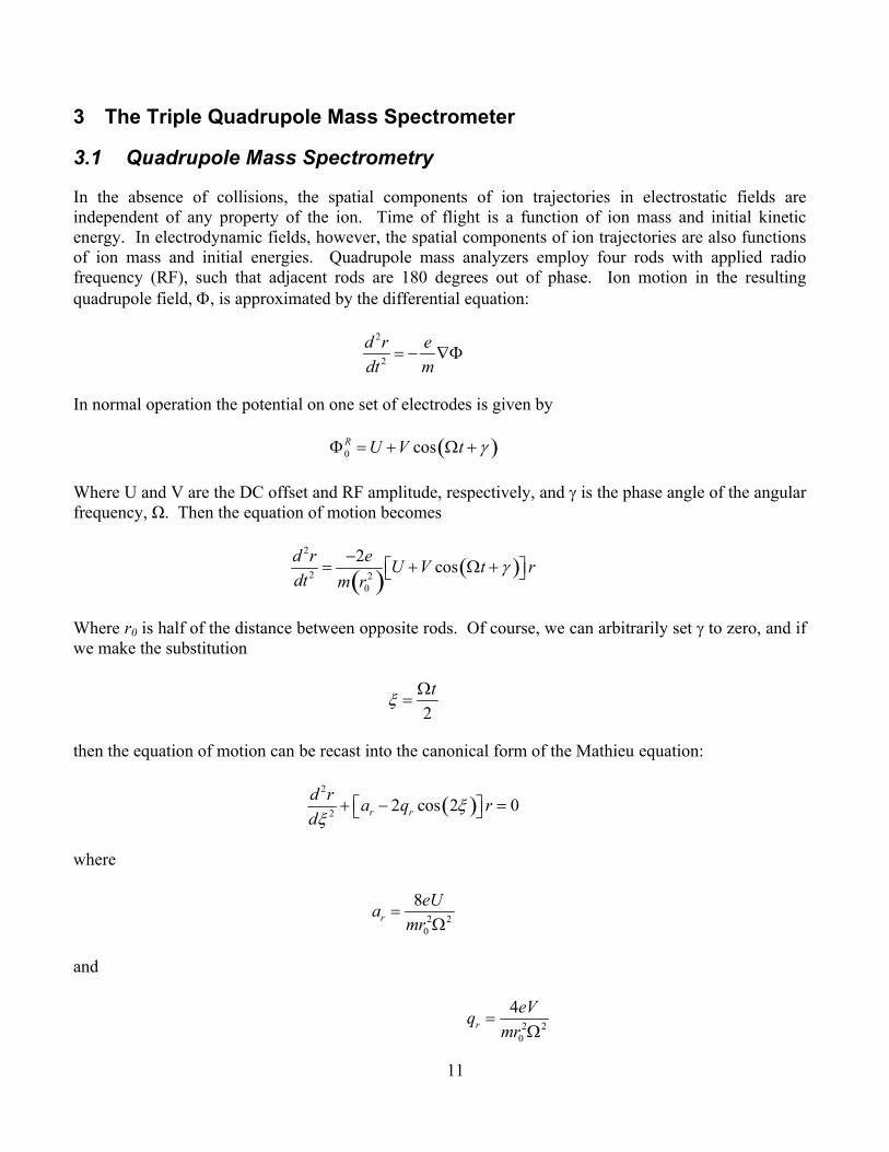
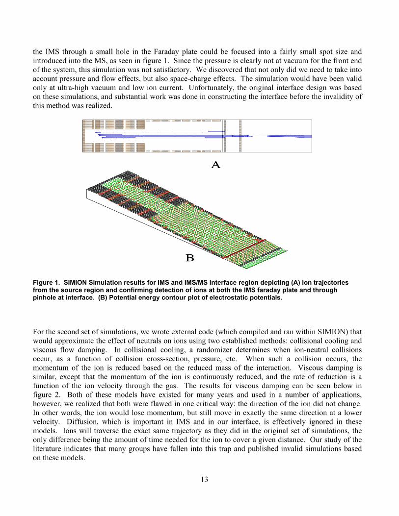
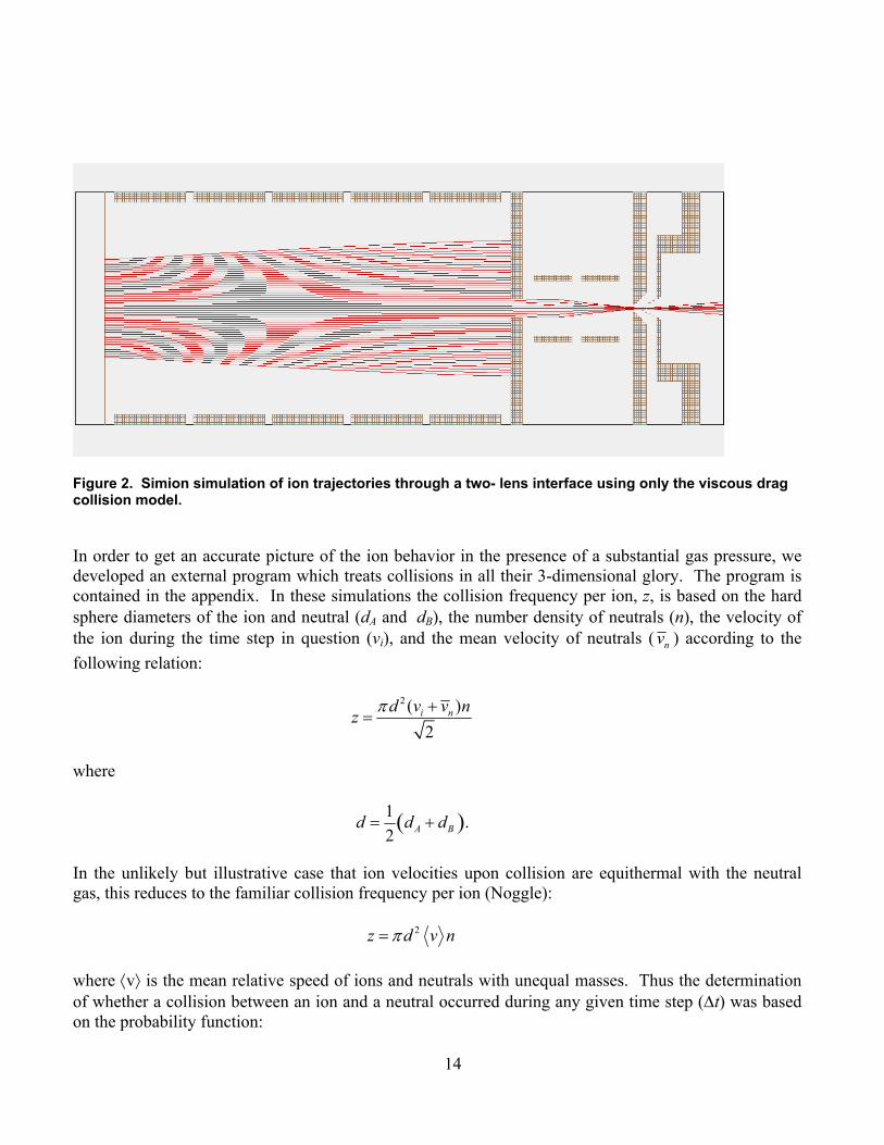
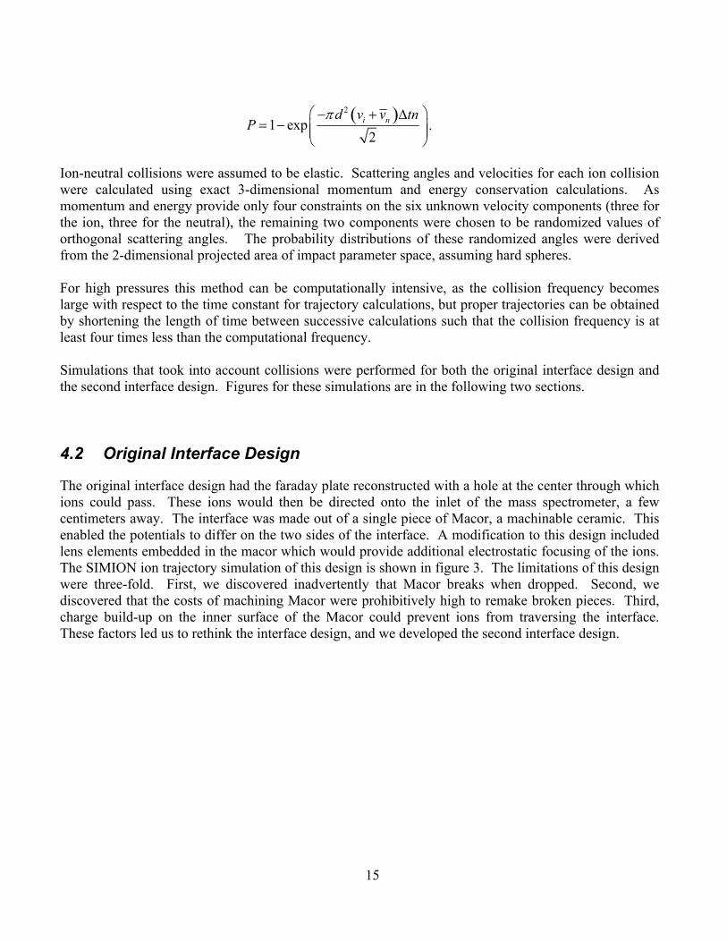
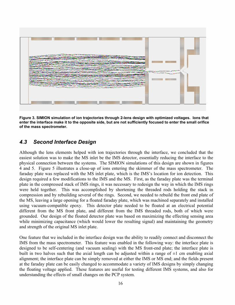
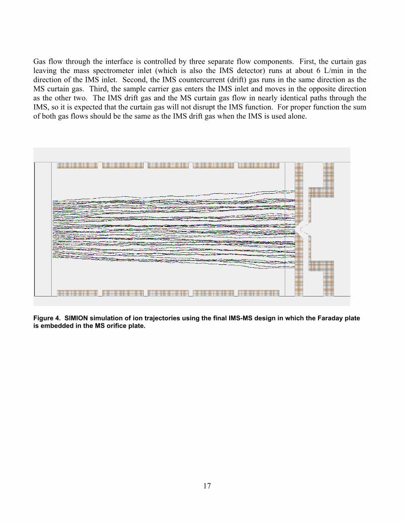
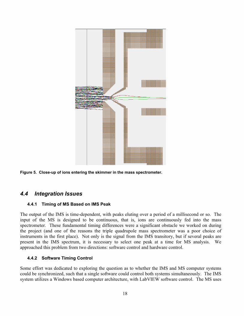
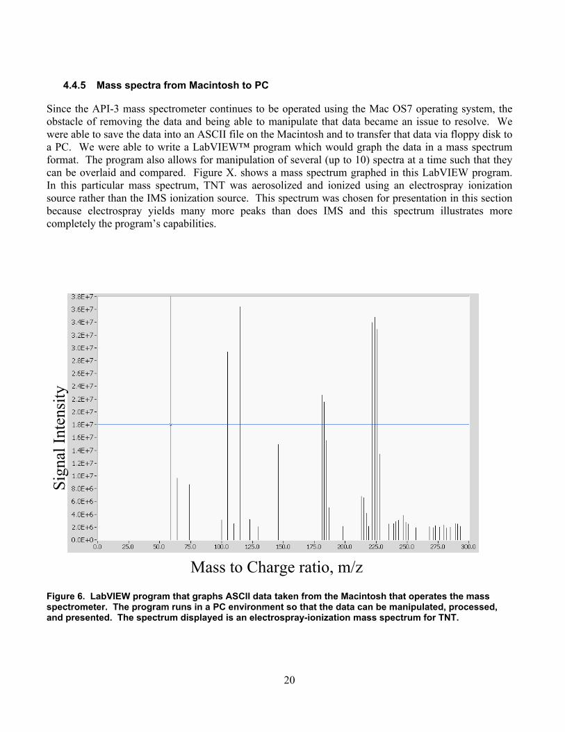
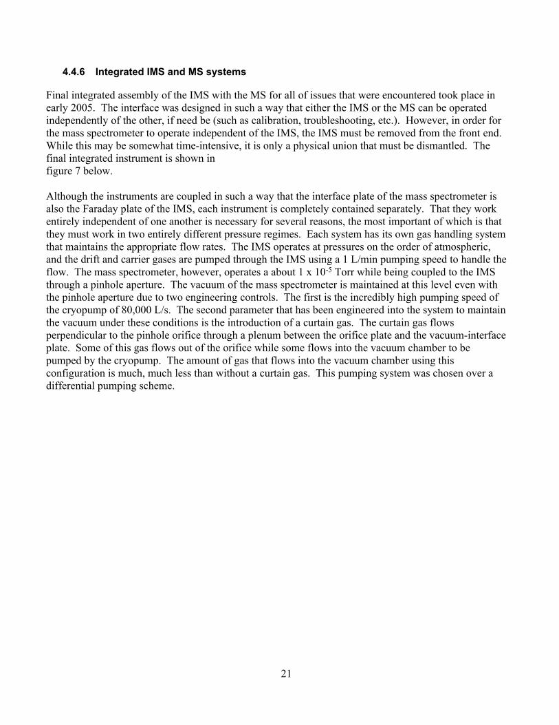
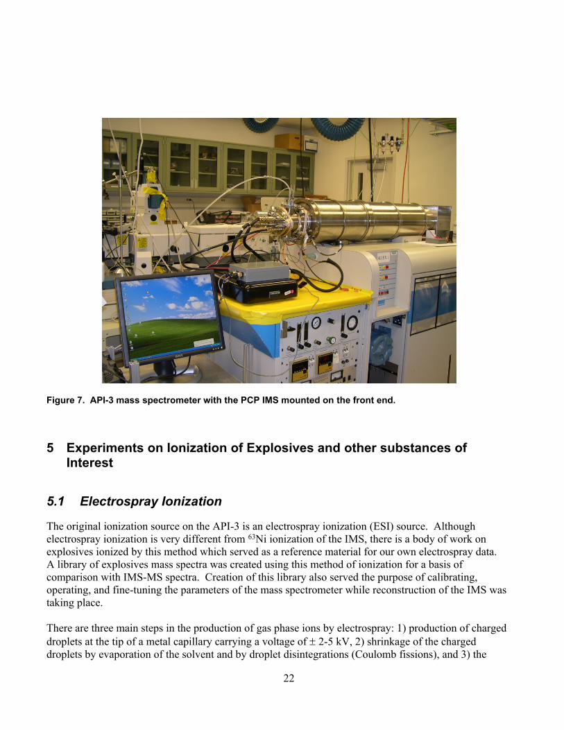
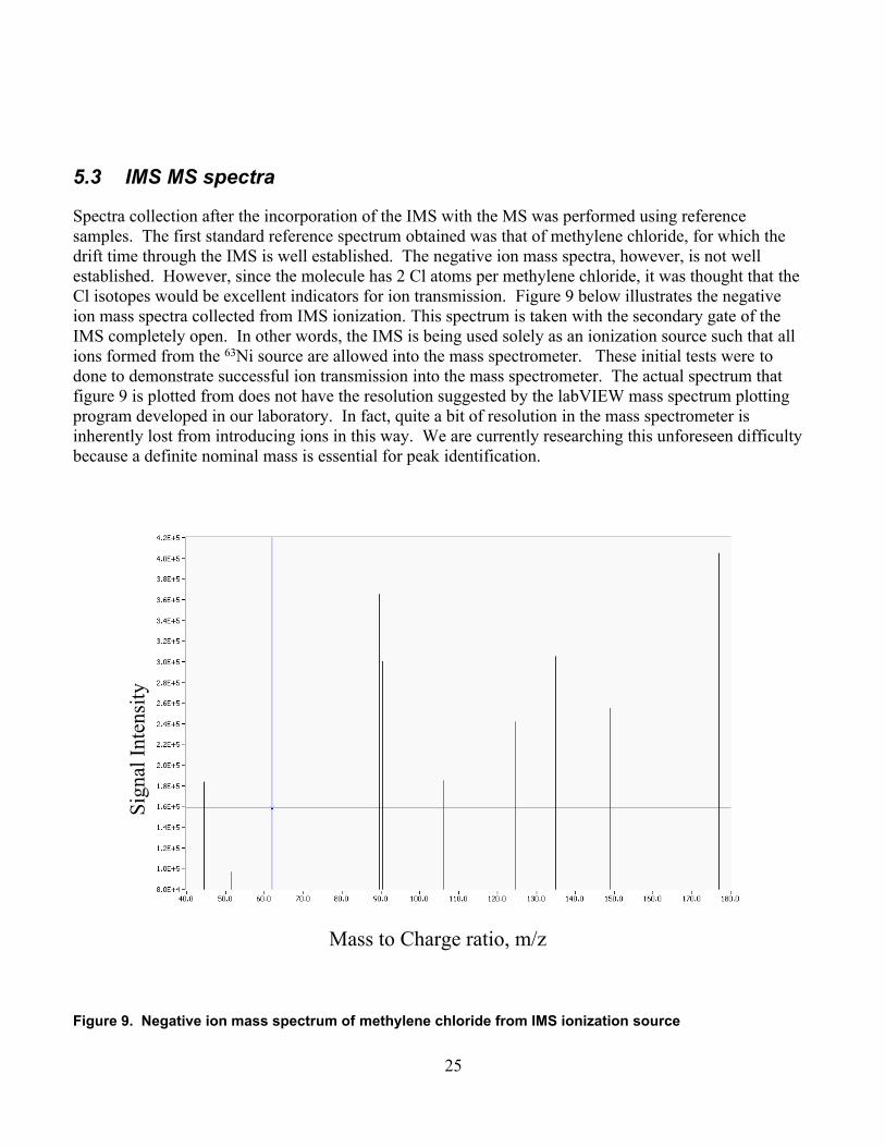
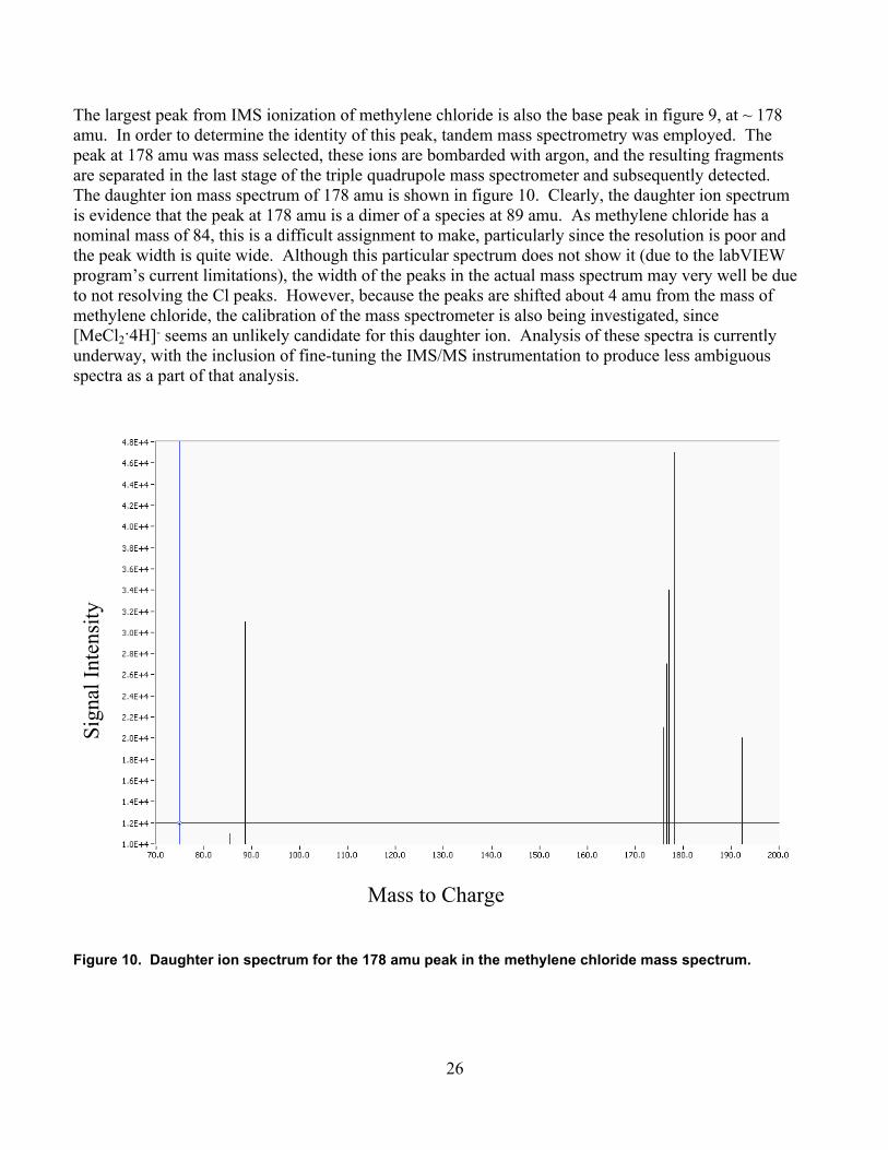
Distribution
1 MS 0123 Donna L Chavez LDRD Office
2 MS 0780 John Hunter 064282 0895 Deborah E Hunka 083321 0782 Charles Rhykerd 064181 0895 Anthony Martino 083321 0780 Steve Ortiz 064281 0782 John E Parmeter
1 MS 0899 Central Technical Files 045352 0899 Technical Library 04535
37