iosrv_mbenet
TRANSCRIPT

Wonderware®
Modicon MODBUS Ethernet I/O Server User’s Guide
Revision F
Last Revision: June 2005
Invensys Systems, Inc.

All rights reserved. No part of this documentation shall be reproduced, stored in a retrieval system, or transmitted by any means, electronic, mechanical, photocopying, recording, or otherwise, without the prior written permission of Invensys Systems, Inc. No copyright or patent liability is assumed with respect to the use of the information contained herein. Although every precaution has been taken in the preparation of this documentation, the publisher and the author assume no responsibility for errors or omissions. Neither is any liability assumed for damages resulting from the use of the information contained herein.
The information in this documentation is subject to change without notice and does not represent a commitment on the part of Invensys Systems, Inc. The software described in this documentation is furnished under a license or nondisclosure agreement. This software may be used or copied only in accordance with the terms of these agreements.
© 2003, 2005 Invensys Systems, Inc. All Rights Reserved.
Invensys Systems, Inc.26561 Rancho Parkway SouthLake Forest, CA 92630 U.S.A.(949) 727-3200http://www.wonderware.com
Trademarks
All terms mentioned in this documentation that are known to be trademarks or service marks have been appropriately capitalized. Invensys Systems, Inc. cannot attest to the accuracy of this information. Use of a term in this documentation should not be regarded as affecting the validity of any trademark or service mark.
Alarm Logger, ActiveFactory, ArchestrA, Avantis, DBDump, DBLoad, DT Analyst, FactoryFocus, FactoryOffice, FactorySuite, FactorySuite A2, InBatch, InControl, IndustrialRAD, IndustrialSQL Server, InTouch, InTrack, MaintenanceSuite, MuniSuite, QI Analyst, SCADAlarm, SCADASuite, SuiteLink, SuiteVoyager, WindowMaker, WindowViewer, Wonderware, and Wonderware Logger are trademarks of Invensys plc, its subsidiaries and affiliates. All other brands may be trademarks of their respective owners.

Contents 3
Contents
Wonderware Modicon MODBUS EthernetI/O Server .............................................................5
Introduction ............................................................................................ 5Communications Protocols................................................................. 5Accessing Remote Items via the I/O Server ....................................... 7
Getting Started........................................................................................ 8
Configuring the I/O Server..................................................................... 9
Configuring a Topic Definition ............................................................ 10Topic Definition................................................................................ 10MBENET Topic Definition ...............................................................11
Saving the I/O Server’s Configuration File.......................................... 16Save Configuration ........................................................................... 16Saving Multiple Configuration Files ................................................ 16
Configuring the I/O Server Settings..................................................... 18Server Settings .................................................................................. 18
Accessing I/O Server Help................................................................... 20Contents ............................................................................................ 20How to Use Help .............................................................................. 20About Modicon MODBUS Ethernet ................................................ 20
Item Names .......................................................................................... 21Special Item/Point Naming Conventions ......................................... 23
Monitoring the Status of Communications with a PLC ....................... 29Using the Status Item in Excel.......................................................... 29
Monitoring the Status of Communications with InTouch .................... 30Using DDEStatus and IOStatus in Excel.......................................... 30 Reading Values from the I/O Server into Excel ............................ 30
Writing Values to the I/O Server from Excel ....................................... 31
Troubleshooting I/O Server Communications Problems ..................... 32Debugging Communications Between InTouch and an I/O Server.. 32Debugging Communications Between SuiteLink and an I/O Server35Debugging Communications Between an I/O Server and a PLC..... 35
Wonderware Modicon MODBUS Ethernet I/O Server

4 Contents
Wonderware Modicon MODBUS Ethernet I/O Server

Wonderware Modicon MODBUS Ethernet I/O Server 5
Wonderware Modicon MODBUS Ethernet I/O Server
IntroductionThe Wonderware® Modicon MODBUS Ethernet I/O Server (referred to as the server through the remainder of this User's Guide) is a Microsoft® Windows® application program that allows access to data in the Modicon PLCs (also referred to as devices) over an Ethernet network.
The server requires only a standard 10BaseT Ethernet network card (or an Ethernet card with fiber optic output) to access the Ethernet network. Each Ethernet Network Card provides an interface to as many PLCs as the Ethernet topology allows. The server supports Modicon Quantum (6-Digit) Automation Series controllers equipped with Quantum Ethernet TCP/IP NOE modules (P/N 140 NOE 211 00 for 10BaseT twisted pair or P/N 140 NOE 251 00 for fiber optic).
While the server is primarily intended for use with Wonderware InTouch®, it may be used by any Microsoft Windows program which is capable of acting as a DDE, FastDDE, or SuiteLink™ client.
Communications ProtocolsDynamic Data Exchange (DDE) is a communications protocol developed by Microsoft to allow applications in the Windows environment to send/receive data and instructions to/from each other. It implements a client-server relationship between two concurrently running applications. The server application provides the data and accepts requests from any other application interested in its data. Requesting applications are called clients. Some applications such as InTouch and Microsoft Excel can simultaneously be both a client and a server.
FastDDE provides a means of packing many proprietary Wonderware DDE messages into a single Microsoft DDE message. This packing improves efficiency and performance by reducing the total number of DDE transactions required between a client and a server. Although Wonderware's FastDDE has extended the usefulness of DDE for our industry, this extension is being pushed to its performance constraints in distributed environments.
SuiteLink uses a TCP/IP-based protocol and is designed specifically to meet industrial needs such as data integrity, high-throughput, and easier diagnostics. This protocol standard is only supported on Microsoft Windows 2000, Windows 2003, and Windows XP.
Wonderware Modicon MODBUS Ethernet I/O Server

6 Wonderware Modicon MODBUS Ethernet I/O Server
SuiteLink is not a replacement for DDE or FastDDE. The protocol used between a client and a server depends on your network connections and configurations. SuiteLink was designed to be the industrial data network distribution standard and provides the following features:
• Value Time Quality (VTQ) places a timestamp and quality indicator on all data values delivered to VTQ-aware clients.
• Extensive diagnostics of the data throughput, server loading, computer resource consumption, and network transport are made accessible through the Microsoft Windows 2000, Windows 2003, and Windows XP operating systems Performance Monitor. This feature is critical for the scheme and maintenance of distributed industrial networks.
• Consistent high data volumes can be maintained between applications regardless if the applications are on a single node or distributed over a large node count.
• The network transport protocol is TCP/IP using Microsoft's standard WinSock interface.
Wonderware Modicon MODBUS Ethernet I/O Server

Wonderware Modicon MODBUS Ethernet I/O Server 7
Accessing Remote Items via the I/O ServerThe communications protocol addresses an element of data in a conversation that uses a three-part naming convention that includes the application name, topic name, and item name. The following briefly describes each portion of this naming convention:
application name The name of the Windows program (server) that will be accessing the data element. In the case of data coming from or going to Modicon equipment via this server, the application portion of the address is MBENET.
topic name Meaningful names are configured in the server to identify specific devices. These names are then used as the topic name in all conversations to that device. For example, Node209.
Note You can define multiple topic names for the same device (PLC) to poll different points at different rates.
item name A specific data element within the specified topic. For example, when using this server, an item can be a relay, timer, counter, register, and so on, in the PLC.
Note The item/point names are predefined by the server. The term "point" is used interchangeably with the term "item" in this User's Guide.
$For more information on item/point names, see the "Item Names" section later in this User's Guide.
Wonderware Modicon MODBUS Ethernet I/O Server

8 Wonderware Modicon MODBUS Ethernet I/O Server
Getting StartedWonderware supplies a version of the server for Microsoft Windows 2000, Windows 2003, and Windows XP. No special Kernel Device Driver is needed. It uses the standard TCP/IP protocol stack that comes with Windows 2000, Windows 2003, or Windows XP operating system.
If you have your Ethernet adapter card configured for accessing the Ethernet network, it will work without modification for communicating with the Modicon Quantum (6-Digit) Series PLCs.
1. Configure the Modicon MODBUS Ethernet module to have a unique valid IP Address on the network to which it is connected.
• You may need to see your Network Administrator to obtain valid IP Addresses.
2. Configure TCP/IP on your computer with a unique IP Address.
3. Make sure that the computer and the PLC or Bridge are either on the same subnet or are connected by routers and/or bridges.
4. To make sure that your computer can communicate with the PLC or Bridge, try pinging the IP Address of the Modicon MODBUS Ethernet module that you are trying to access.
Wonderware Modicon MODBUS Ethernet I/O Server
Wonderware Modicon MODBUS Ethernet I/O Server 9
Configuring the I/O ServerOnce the server has been installed, a small amount of configuration is required. Configuring the server automatically creates a configuration file named, MBENET.CFG. This file stores the configuration information for the adapter cards or communications ports and all of the topic definitions (described in detail later).
The configuration file is automatically saved to the directory in which the server is installed unless a different directory is specified.
To perform the required configurations
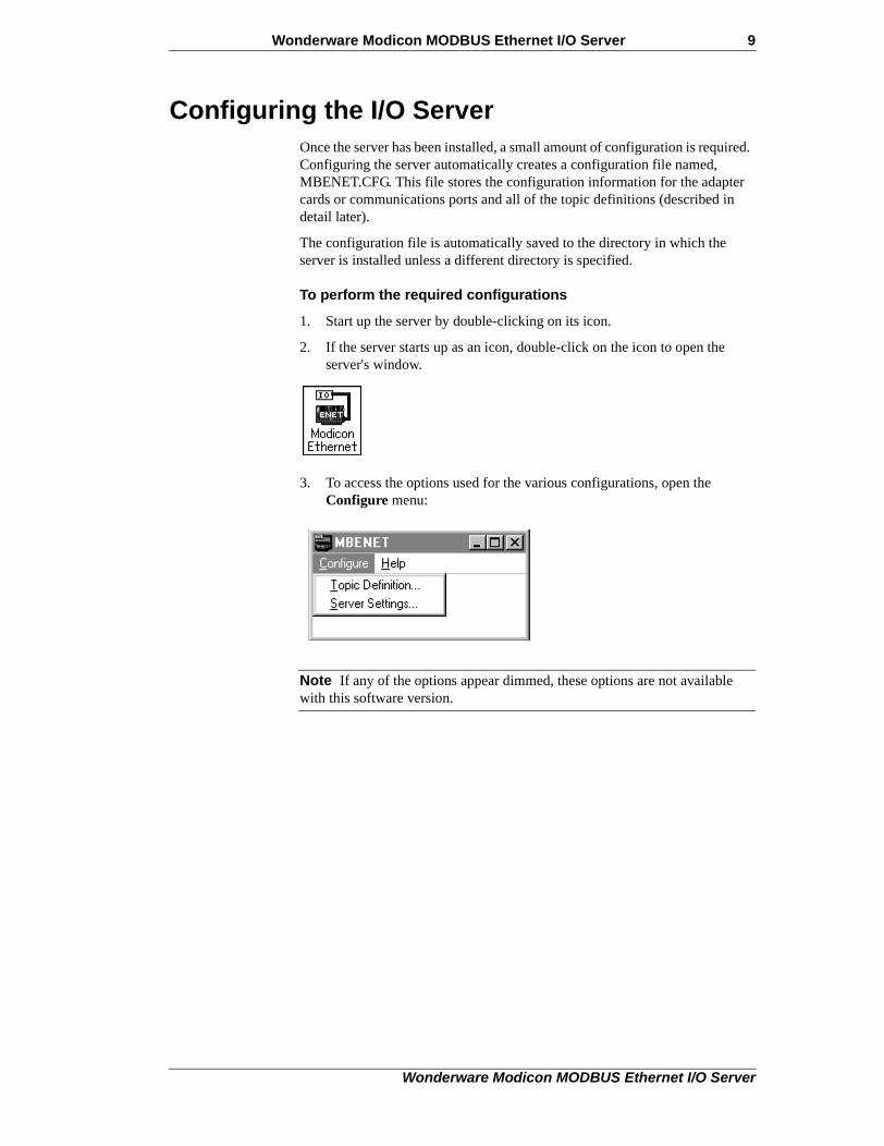
1. Start up the server by double-clicking on its icon.
2. If the server starts up as an icon, double-click on the icon to open the server's window.
3. To access the options used for the various configurations, open the Configure menu:
Note If any of the options appear dimmed, these options are not available with this software version.
Wonderware Modicon MODBUS Ethernet I/O Server

10 Wonderware Modicon MODBUS Ethernet I/O Server
Configuring a Topic DefinitionUse the Topic Definition option from the Configure menu to create new, modify, or delete topic definitions.
• One or more topic definitions must exist for each PLC that the server will communicate with.
• Each topic definition must contain a unique name for the PLC associated with it.
• When this option is selected, the Topic Definition dialog box will appear
Topic Definition
Note Once topics have been defined, their names will be listed in the Topics section of this dialog box.
• Click this Done button to close the dialog box and accept any new definitions, modifications, or deletions made.
• To modify or view an existing topic definition, select its name in the list and click on the Modify button.
• The MBENET Topic Definition dialog box (described below) will appear displaying the selected topic definition.
• To delete an existing topic definition, select its name in the list and click on this Delete button.
• A message box will appear prompting you to confirm the deletion.
Wonderware Modicon MODBUS Ethernet I/O Server

Wonderware Modicon MODBUS Ethernet I/O Server 11
• To add a new topic definition, click on the New button.
• The MBENET Topic Definition dialog box will appear.
• The number of new topics per PLC (IP Address) is limited to 16 topics per PLC.
MBENET Topic Definition
1. Enter a unique name (up to 32-characters long) for the PLC in this box.
For example:
Node209
Note When communicating with InTouch, this exact name is used as the topic name in the Access Name definition.
2. Enter the unique IP Address that was configured in the Quantum (6-Digit) PLC.
• If your computer has access to a Domain Name Server or a HOST file, then enter the name of the Quantum (6-Digit) host PLC.
Wonderware Modicon MODBUS Ethernet I/O Server

12 Wonderware Modicon MODBUS Ethernet I/O Server
• The HOST file is an ASCII text file that maps user-friendly host names to IP Addresses.
An example of a HOST file entry would be:
10.32.200.209 Wonder0 wonder0
• In this case, enter Wonder0 or wonder0 in the Edit box for the IP Address.
• If the computer is located on a remote network, then a fully qualified domain name may be required in the HOST file.
For example:
10.32.200.209 mbe2.wonderware.com
3. In this case, enter mbe2.wonderware.com in the Edit box.
• It is recommended to enter the IP Address, if available.
• This is faster because the server does not have to resolve the name to an IP Address.
• The number of new topics per PLC (IP Address) is limited to 16 topics per PLC.
4. Enter the Dest_Index if you are using the MODBUS Plus to Ethernet bridge.
• Enter the Unit_ID if you are using the MODBUS to Ethernet bridge.
• This value may contain any integer from 0 to 255.
5. From the drop-down list box, select the Slave Device Type.
• The Block I/O Sizes will automatically change when a new slave type is selected
6. Select this option to configure the server to be compatible with the Modicon Concept software data structures.
• Only active for six-digit devices.
Wonderware Modicon MODBUS Ethernet I/O Server

Wonderware Modicon MODBUS Ethernet I/O Server 13
7. Check the Unsolicited Messages box to allow the server to accept unsolicited messages.
• The Quantum (6-Digit) PLC must be programmed using an MSTR block to send messages back to the computer that is running the server.
• Use the IP Address of the computer in the MSTR block.
• If the Update Interval value is non-zero, the server will poll for the data in this topic in addition to accepting unsolicited messages.
• For unsolicited messages to work, your InTouch application must have the items on advise.
• Program the MSTR block to send messages that contain data for these items.
8. Select the option for the style the server uses to store ASCII strings into the PLC registers.
Note For more information on the String Variable Styles, see the "Item Names" section in this User's Guide.
9. Select the option for the Register Type being used.
• The following Block I/O Size examples are for the Quantum (6-Digit) Series Slave Type.
10. Enter the maximum number of consecutive coils to be read at one time in this box.
• In this example, the valid Coil Read values can be between 8 to 1600 and must be an even multiple by 8.
Wonderware Modicon MODBUS Ethernet I/O Server
14 Wonderware Modicon MODBUS Ethernet I/O Server
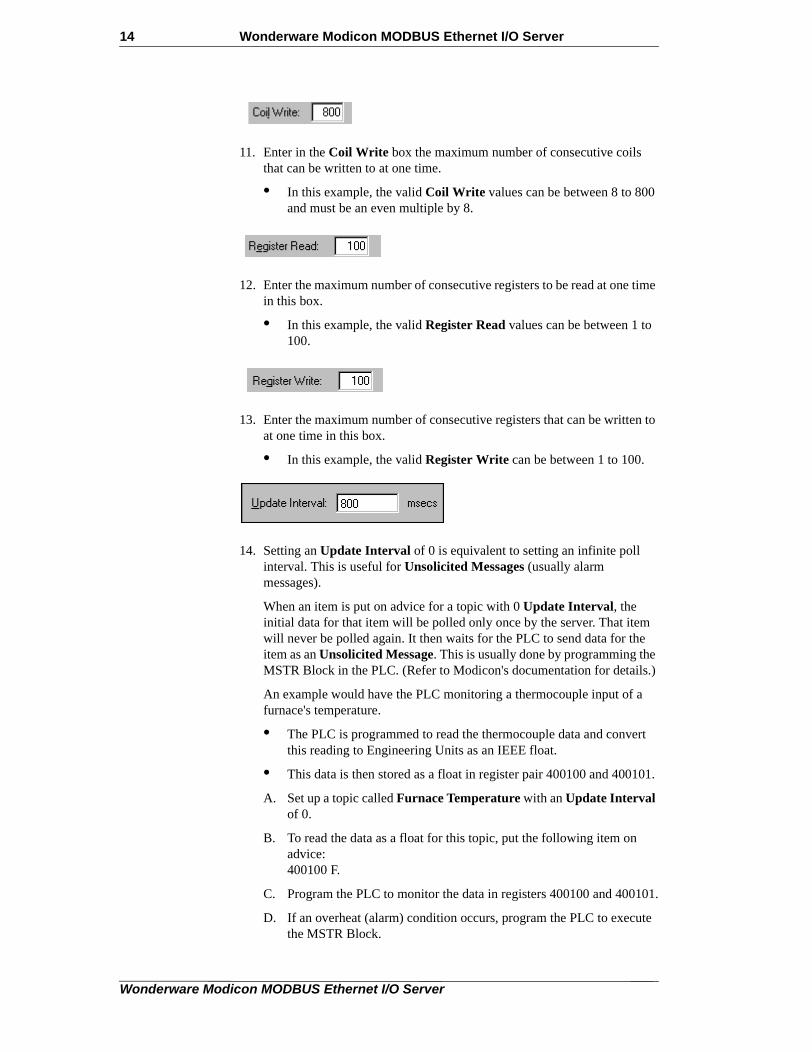
11. Enter in the Coil Write box the maximum number of consecutive coils that can be written to at one time.
• In this example, the valid Coil Write values can be between 8 to 800 and must be an even multiple by 8.
12. Enter the maximum number of consecutive registers to be read at one time in this box.
• In this example, the valid Register Read values can be between 1 to 100.
13. Enter the maximum number of consecutive registers that can be written to at one time in this box.
• In this example, the valid Register Write can be between 1 to 100.
14. Setting an Update Interval of 0 is equivalent to setting an infinite poll interval. This is useful for Unsolicited Messages (usually alarm messages).
When an item is put on advice for a topic with 0 Update Interval, the initial data for that item will be polled only once by the server. That item will never be polled again. It then waits for the PLC to send data for the item as an Unsolicited Message. This is usually done by programming the MSTR Block in the PLC. (Refer to Modicon's documentation for details.)
An example would have the PLC monitoring a thermocouple input of a furnace's temperature.
• The PLC is programmed to read the thermocouple data and convert this reading to Engineering Units as an IEEE float.
• This data is then stored as a float in register pair 400100 and 400101.
A. Set up a topic called Furnace Temperature with an Update Interval of 0.
B. To read the data as a float for this topic, put the following item on advice: 400100 F.
C. Program the PLC to monitor the data in registers 400100 and 400101.
D. If an overheat (alarm) condition occurs, program the PLC to execute the MSTR Block.
Wonderware Modicon MODBUS Ethernet I/O Server

Wonderware Modicon MODBUS Ethernet I/O Server 15
• This could be programmed to send the data in register block 400100 to 400101 to the target computer workstation where the server is running.
• By setting the IP Address of the computer workstation, the client program in the computer workstation could be set up to display the data.
15. Enter the amount of time (in seconds) that the PLCs for this topic will be given to reply to commands from the server.
16. Click Cancel to close the dialog box without saving changes.
17. Click OK to accept the topic definition and return to the Topic Definition dialog box.
18. Click Done to close this dialog box.
Wonderware Modicon MODBUS Ethernet I/O Server

16 Wonderware Modicon MODBUS Ethernet I/O Server
Saving the I/O Server’s Configuration FileIf a configuration file does not currently exist in the configuration file directory, the server will automatically display the Save Configuration dialog box:
Save Configuration
This text box displays the drive\directory into which the server will save the current configuration file.
• To save the configuration file to a different directory, enter the path for that directory in this box.
This option is selected and disabled on initial entry to the Save Configuration dialog box.
• This check box becomes selectable if the Configuration File Directory is changed.
• Once enabled, selecting this option will record a new Configuration File path in the WIN.INI file.
• This option allows the server to find its configuration file automatically each time it is started.
Note When the server initially starts up, it attempts to locate its default configuration file by first checking the WIN.INI file for a previously specified path. If a path is not present in the WIN.INI file, the server will assume that the current working directory is to be used.
• Click Defaults to reset the settings to their default values without saving changes.
• Click OK to save the configuration file to the specified directory.
Saving Multiple Configuration FilesThere is no limit to the number of configuration files that you can create as long as they are saved in separate directories.
Wonderware Modicon MODBUS Ethernet I/O Server

Wonderware Modicon MODBUS Ethernet I/O Server 17
• This allows you to have multiple configuration files that can be accessed by using a special switch (/d:).
For example:
1. To start the server using a configuration file located in a different directory, click the Start button on the Taskbar.
2. Select Run and enter the following in the Open combo box:
MBENET /d:c:\directoryname
Wonderware Modicon MODBUS Ethernet I/O Server
18 Wonderware Modicon MODBUS Ethernet I/O Server
Configuring the I/O Server SettingsUse the Server Settings option from the Configure menu to change the protocol timer, change the default configuration file path, or to enable the server to start automatically as a Windows 2000, Windows 2003, or Windows XP service.
Note When configuring the server on Windows 2000, Windows 2003, or Windows XP, you must be logged on with system administrator privileges. This will ensure that updates to the system registry may be performed.
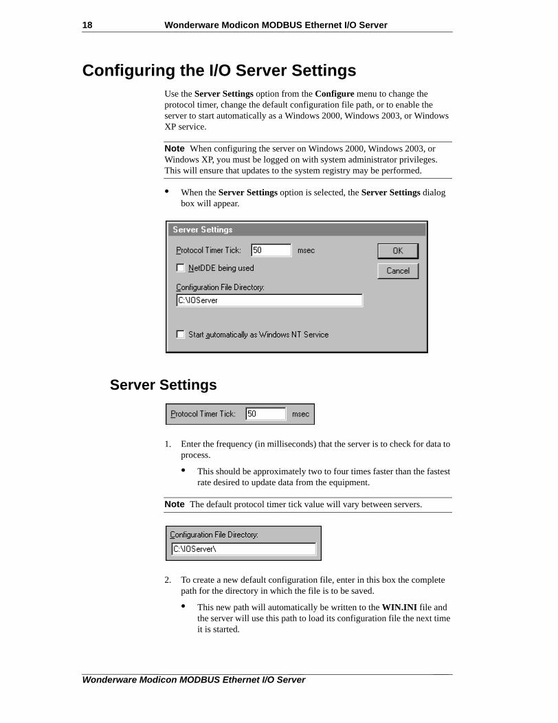
• When the Server Settings option is selected, the Server Settings dialog box will appear.
Server Settings
1. Enter the frequency (in milliseconds) that the server is to check for data to process.
• This should be approximately two to four times faster than the fastest rate desired to update data from the equipment.
Note The default protocol timer tick value will vary between servers.
2. To create a new default configuration file, enter in this box the complete path for the directory in which the file is to be saved.
• This new path will automatically be written to the WIN.INI file and the server will use this path to load its configuration file the next time it is started.
Wonderware Modicon MODBUS Ethernet I/O Server

Wonderware Modicon MODBUS Ethernet I/O Server 19
Note There is no limit to the number of configuration files created. However, each must be saved in a different directory. When using the server with InTouch, we recommend that you save the configuration file in your application directory. For more information on the Configuration File, see "Saving the I/O Server’s Configuration File" in this User's Guide.
3. Enable this option for the server to start as a Windows 2000, Windows 2003, or Windows XP operating system service.
• Windows 2000, Windows 2003, or Windows XP offers the capability of running applications even when a user is not logged on to the system. This is valuable when systems must operate in an unattended mode.
• Enabling this option and rebooting the system will cause the server to run as a Windows 2000, Windows 2003, or Windows XP service.
Note However, to view configuration information or to reconfigure the server, you must log on to the system. Any server-related problems that may arise, such as missing adapter cards, licensing failures, or device drivers not loading will not be visible to the user until a logon is performed.
4. Disabling this option and restarting the system will cause the server to run as a Windows application program once again.
Note It is highly recommended that the server is configured and communicating successfully prior to running it as a Windows 2000, Windows 2003, or Windows XP operating system service.
5. Click Cancel to close the dialog box without saving changes.
6. Click OK to accept the server settings.
• The following message box will appear.
7. Click OK to close the dialog box.
Note You must restart the server for the changes to take effect.
Wonderware Modicon MODBUS Ethernet I/O Server

20 Wonderware Modicon MODBUS Ethernet I/O Server
Accessing I/O Server HelpThe Help menu contains three options that are used to access Help for the server.
• Contents
• How to Use Help
• About Modicon MODBUS Ethernet
The following briefly describes the Help menu options.
ContentsThis option is used to display the table of contents for the Help file.
How to Use HelpThis option is used to access a list of basic instructions for using the Help file.
About Modicon MODBUS EthernetThis option is used to access miscellaneous information regarding the server such as the software version, the copyright information, license information, and so on.
Your FactorySuite system license information can be viewed through the license viewing utility that is launched from the About dialog box.
• For more information on the license viewing utility, see your online FactorySuite System Administrator's Guide.
Wonderware Modicon MODBUS Ethernet I/O Server
Wonderware Modicon MODBUS Ethernet I/O Server 21
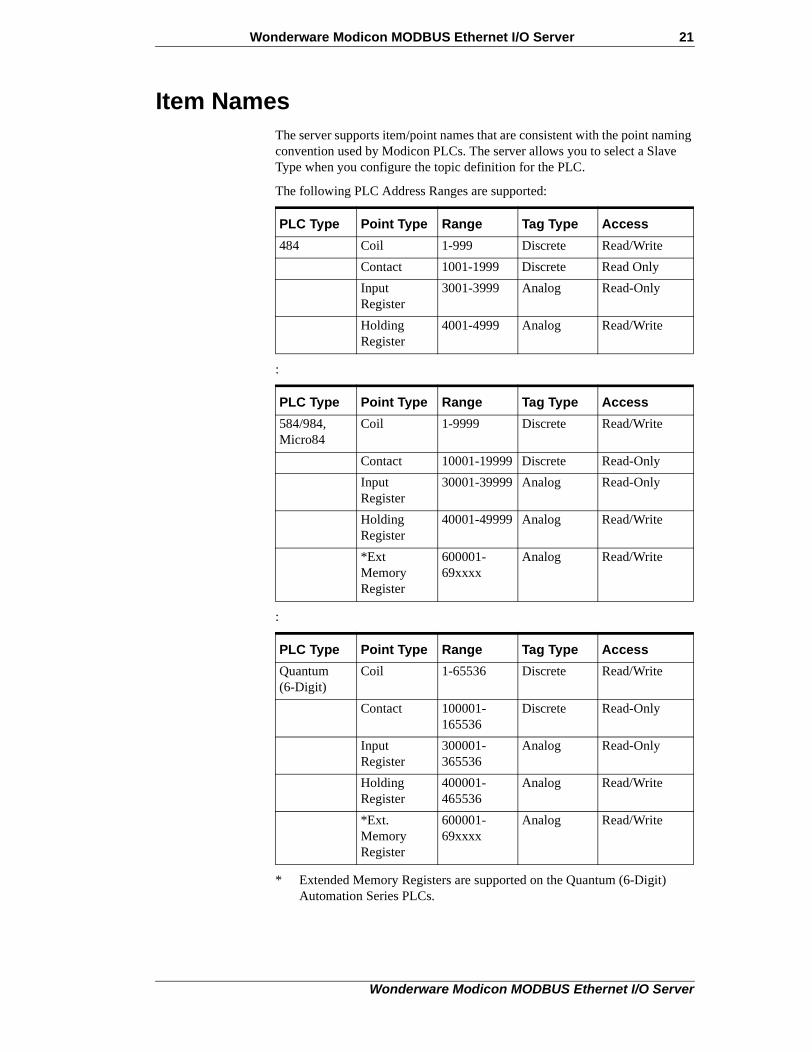
Item NamesThe server supports item/point names that are consistent with the point naming convention used by Modicon PLCs. The server allows you to select a Slave Type when you configure the topic definition for the PLC.
The following PLC Address Ranges are supported:
:
:
* Extended Memory Registers are supported on the Quantum (6-Digit) Automation Series PLCs.
PLC Type Point Type Range Tag Type Access
484 Coil 1-999 Discrete Read/Write
Contact 1001-1999 Discrete Read Only
Input Register
3001-3999 Analog Read-Only
Holding Register
4001-4999 Analog Read/Write
PLC Type Point Type Range Tag Type Access
584/984, Micro84
Coil 1-9999 Discrete Read/Write
Contact 10001-19999 Discrete Read-Only
Input Register
30001-39999 Analog Read-Only
Holding Register
40001-49999 Analog Read/Write
*Ext Memory Register
600001-69xxxx
Analog Read/Write
PLC Type Point Type Range Tag Type Access
Quantum(6-Digit)
Coil 1-65536 Discrete Read/Write
Contact 100001-165536
Discrete Read-Only
Input Register
300001-365536
Analog Read-Only
Holding Register
400001-465536
Analog Read/Write
*Ext. Memory Register
600001-69xxxx
Analog Read/Write
Wonderware Modicon MODBUS Ethernet I/O Server

22 Wonderware Modicon MODBUS Ethernet I/O Server
Addresses are assigned as follows:
Note Analog tagnames can be either Integer or Real.
The supported Item Names for Daniel FC, Elliott FC, Omni FC, and Micromotion slave-device types are consistent with the Item Names used by Modicon PLCs. However, the Item Name and Read/Write Access may vary depending upon the application being used. For more information, see your User's Guide for the device being used.
The following Flow Computer Address Ranges are supported:
File# Range
1 600001-610000
2 610001-620000
3 620001-630000
4 630001-640000
5 640001-650000
6 650001-660000
7 660001-670000
8 670001-680000
9 680001-690000
10 690001-69xxxx
FC Type Point Type Range Tag Type
Daniel Coil 1001 - 2999 Discrete
Holding Register 3001 - 4999 Integer
Holding Register 5001 - 6999 Integer
Holding Register 7001 - 65535 Real
FC Type Point Type Range Tag Type
Elliot Coil 1001 - 2999 Discrete
Holding Register 3001 - 4999 Integer
Holding Register 5001 - 6999 Integer
Holding Register 7001 - 65535 Real
FC Type Point Type Range Tag Type
Omni Coil 1001-2999 Discrete
Holding Register 3001 - 4999 Integer
Holding Register 4001-4999 String
Holding Register 5001-6999 Integer
Holding Register 7001-7999 Real
Wonderware Modicon MODBUS Ethernet I/O Server

Wonderware Modicon MODBUS Ethernet I/O Server 23
* Registers 50052 - 50119 map to 40052 - 40119.To access the first ASCII string located at 50052 - 50055, use item name 40052 - 40055 M. The other ASCII strings are accessed in the same way.
** Caution! Advise-only items within the ranges shown.
*** To access a float located at register pair 20141 - 20142, use the item name 40141 F. Other floats are accessed in the same way.
Note Floating Point Registers must be accessed as pairs only.
Special Item/Point Naming ConventionsSpecial handling of data from Modicon equipment can be done by using the following conventions:
Signed RegistersThe server normally allows register values in the range of 0 to 65535.
• Registers may be treated as 16-bit signed quantities having values between -32,768 and 32,767.
• To specify that a register is to be treated as a signed quantity, append a space and the letter S to the item name.
Holding Register 13001-13999 Integer
Holding Register 14001-14999 String
Holding Register 15001-16999 Integer
Holding Register 17001-17999 Real
FC Type Point Type Range Tag Type
Micromotion **Coil 00002 - 00020 Discrete
**Coil 00113 - 00160 Discrete
**Read-Only Discrete
10021 - 10038 Discrete
Input Register 30001 - 30011 Integer
Input Register 30120 - 30126 Integer
Holding Register 40012 - 40051 Integer
*Strings 40052 - 40119 String
Holding Register 40124 - 40140 Integer
***Floating Point Register Pairs
40141 - 40278 Real
FC Type Point Type Range Tag Type
Wonderware Modicon MODBUS Ethernet I/O Server

24 Wonderware Modicon MODBUS Ethernet I/O Server
For example:To indicate that the first Holding Register is signed, enter "400001 S" for the item name.
Long IntegersPairs of registers can be treated as 32-bit signed integers.
• This is done by appending a space and the letter L to the item name.
For example: 400001 L
Floating PointPairs of registers can be treated as IEEE 32-bit floating point numbers.
• This is done by appending a space and the letter F to the item name.
For example: 400001 F
Bits In RegistersIndividual bits in registers can be read as discrete tags by using the notation rrrr:b.
• Where rrrr specifies a valid input register or holding register and b specifies a bit position between 1 and 16 (1 specifies the most significant bit of the register).
Examples:
400001:1 - Most significant bit of first holding register
300008:16 - Least significant bit of an input register
Note Bits in registers are read-only. The Ethernet protocol has no commands to write individual register bits.
Explicit ConversionsRegisters are normally treated as integers.
• This can be altered for specific registers by adding a blank space (using the spacebar) and one of the following to the point name:
L - Long
F - Float
I - Integer
M - Message (ASCII Strings)
Modulo-10000 PointsTwo or three consecutive registers may be interpreted as a single numeric quantity.
Wonderware Modicon MODBUS Ethernet I/O Server

Wonderware Modicon MODBUS Ethernet I/O Server 25
• In doing so, each of the component registers must be in the range of 0-9999.
For example:
Two registers "400001-400002" can represent numbers between 0 and 99999999.
Overflow becomes a possibility when grouping three consecutive registers for interpretation as a single numeric quantity.
• The largest number that may be represented in the PLC with three consecutive Modulo-10000 registers is 999,999,999,999.
• Unfortunately, the largest number which can be contained in an 'integer' type variable is 2,147,483,647. The latter number is used by the server to represent an overflow condition.
• Therefore, the maximum usable value represented in three Modulo-10000 registers is 2,147,483,646 ( or < 21 >< 4748 >< 3646 > ).
• Any numbers larger than this will be clamped at 2,147,483,647.
ASCII StringsMultiple consecutive registers (1-100) can be treated as a string of ASCII characters.
• The first character of the string is in the high-order 8 bits of the lowest numbered register.
• Three options are provided for the representation of variable length strings:
A. The string may be padded with ASCII spaces (hex 20).
B. The string may be terminated with a zero byte.
C. The length may be stored in the first byte.
Strings of ASCII characters can be stored in consecutive registers in a PLC.
• The number of registers that are allocated to the storage of an individual string must be fixed.
• However, the string contained in those registers can have a variable length up to twice the number of registers allocated.
• Strings are stored in the PLC registers from the lowest numbered register to the highest and within each register, first the most significant byte, then the least significant byte.
• The server supports three methods of storing strings of ASCII characters in registers: Full Length, C Style, and Pascal Style.
Full LengthIf strings are stored in this manner, the string always uses all of the registers allocated.
• If the string is shorter than the allocation of registers, it is padded with ASCII space characters (hex 20) to the full length.
Wonderware Modicon MODBUS Ethernet I/O Server

26 Wonderware Modicon MODBUS Ethernet I/O Server
For example:
String item "400001-400010 M" containing the ASCII string "Wonderware":
C StyleIf strings are stored in this manner, the end of the string is marked by a byte of zero immediately following the last character in the string.
• This option is so named because this is the way strings are stored in the "C" programming language.
For example:
String item "40001-40010 M" containing the ASCII string "Wonderware":
Pascal StyleIf strings are stored in this manner, the length of the string is denoted by a length byte which occupies the first byte of the string (MSB of the first register).
• This option is so named because this is the way strings are stored in the "Pascal" programming language (for most compilers).
MSB LSB
400001 57 6F "Wo"
400002 6E 64 "nd"
400003 65 72 "er"
400004 77 61 "wa"
400005 72 65 "re"
400006 20 20 " "
400007 20 20 " "
400008 20 20 " " padded to the end
400009 20 20 " " with ASCII spaces
400010 20 20 " "
MSB LSB
400001 57 6F "Wo"
400002 6E 64 "nd"
400003 65 72 "er"
400004 77 61 "wa"
400005 72 65 "re"
400006 0 x end marked by zero
400007 x x the remaining
400008 x x bytes
400009 x x are
400010 x x unused
Wonderware Modicon MODBUS Ethernet I/O Server

Wonderware Modicon MODBUS Ethernet I/O Server 27
For example:
String item "400001-400010 M" containing the ASCII string "Wonderware":
Absolute NotationAbsolute item naming conventions are available that are independent of PLC model numbers.
• The absolute notation allows accessing of the four Ethernet data types, each with an address from 0 to 65535.
• The data types are indicated by the item name suffix characters as follows:
The IR and HR absolute notations can also be combined with the following conversions: L (long), F (floating point), or S (signed).
MSB LSB
400001 0A 57 length = 0A (hex) "W"
400002 6F 6E "on"
400003 64 65 "de"
400004 72 77 "rw"
400005 61 72 "ar"
400006 65 x "e"
400007 x x the remaining
400008 x x bytes
400009 x x are
400010 x x unused
nnnnn DO (Discrete Output)Refers to the same data Ethernet calls "coils" (valid range is 0 DO through 65535 DO).
nnnnn DI (Discrete Input)Refers to the same data Ethernet calls "contacts" (valid range is 0 DI through 65535 DI).
nnnnn IR (Input Registers)Refers to the same data Ethernet calls "input registers" (valid range is 0 IR through 65535 IR).
nnnnn HR (Holding Registers)Refers to the same data Ethernet calls "holding registers" (valid range is 0 HR through 65535 HR).
nnnnn PV (Process Variable)Refers to holding registers but treats them as floating points and assumes 2 registers per floating point number. The valid range is 0 PV through 32767 PV.
Wonderware Modicon MODBUS Ethernet I/O Server

28 Wonderware Modicon MODBUS Ethernet I/O Server
For example: :
Unsolicited DataUnsolicited Data has no special point naming conventions. However, due to the architecture of the Modicon PLCs, only 4xxxxx tags may be specified to be read with unsolicited messages.
Global DataThe server does not support Global Data.
219 HRS 16-bit signed integer
0 HRL 32-bit signed integer
100 HRF 32-bit floating point
Wonderware Modicon MODBUS Ethernet I/O Server

Wonderware Modicon MODBUS Ethernet I/O Server 29
Monitoring the Status of Communications with a PLC
For each topic name (PLC), there is a built-in discrete item that can be used to monitor the status of communications with the PLC.
• The discrete item, Status, is set to 0 when communications with the PLC fails.
• It is set to 1 when communications is successful.
Using the Status Item in ExcelThe status of the PLC communications can be read into Excel by entering the following DDE reference formula in a cell on a spreadsheet:
=MBENET|Node209!Status
where:
MBENET Is the name of the server application.
Node209 Is the exact topic name defined in the server for the PLC.
Status Built-in discrete item used to monitor the status of communications with the PLC.
Wonderware Modicon MODBUS Ethernet I/O Server

30 Wonderware Modicon MODBUS Ethernet I/O Server
Monitoring the Status of Communications with InTouch
InTouch supports built-in topic names called DDEStatus and IOStatus that are used to monitor the status of communications between the server and InTouch. For more information on the built-in topic names DDEStatus and IOStatus, see your online "InTouch User's Guide."
Using DDEStatus and IOStatus in ExcelThe status of communications between the server and InTouch can be read into Excel by entering the following DDE reference formula in a cell on a spreadsheet:
=view|DDEStatus!Node209
or
=view|IOStatus!Node209
where:
Reading Values from the I/O Server into ExcelValues may be read directly into Excel spreadsheets from the server by entering a DDE formula into a cell using the following format:
=applicationname|topicname!'itemname'
Example formula:
=MBENET|Node209!'400001'
Where:
In this example, each time the value of 400001 changes in the PLC, the server will automatically send the new value to the cell containing the formula in Excel.
Note Refer to the Microsoft Excel manual for complete details on entering Remote Reference formulas for cells.
view Is the name of the InTouch application.
[DDE][IO]Status Built-in topic name used to monitor the status of communications between the server and InTouch.
Node209 The exact topic name defined in the server for the PLC.
MBENET Is the name of the server application.
Node209 Is the exact topic name defined in the server for the PLC.
400001 Is the actual location in the PLC that contains the data value. This is the item name.
Wonderware Modicon MODBUS Ethernet I/O Server

Wonderware Modicon MODBUS Ethernet I/O Server 31
Writing Values to the I/O Server from ExcelValues may be written to the server from Microsoft Excel by creating an Excel macro that uses the POKE command. The proper command is entered in Excel as follows:
channel=INITIATE("applicationname","topicname")
=POKE(channel,"itemname", Data_Reference)
=TERMINATE (channel)
=RETURN()
The following describes each of the above POKE macro statements:
channel=INITIATE("applicationname","topicname")
Opens a channel to a specific topic name (defined in the server) in a particular application name (the executable name less the .EXE) and assigns the number of that opened channel to channel.
Note By using the channel=INITIATE statement the word channel must be used in the =POKE statement instead of the actual cell reference. The "applicationname" and "topicname" portions of the formula must be enclosed in quotation marks.
=POKE(channel,"itemname", Data_Reference)
POKEs the value contained in the Data_Reference to the specified item name (actual location in the PLC) via the channel number returned by the previously executed INITIATE function
• Data_Reference is the row/column ID of the cell containing the data value.
=TERMINATE(channel)
Closes the channel at the end of the macro.
• Some applications have a limited number of channels therefore, they should be closed when finished.
• Channel is the channel number returned by the previously executed INITIATE function.
=RETURN()
Marks the end of the macro.
Note Refer to the .XLM sample Excel poke macro provided in the installed server’s directory. Also refer to the Microsoft Excel manual for complete details on entering Remote Reference formulas for cells.
Wonderware Modicon MODBUS Ethernet I/O Server

32 Wonderware Modicon MODBUS Ethernet I/O Server
Troubleshooting I/O Server Communications Problems
This section provides you with some simple steps that can be taken to ascertain and correct communications problems. The problems described here represent the most probable causes of communications failure.
Note This is a general troubleshooting guide and for the sake of brevity we cannot cover every possible source of communications problems.
Debugging Communications Between InTouch and an I/O Server
This section explains the most common error situations that can occur when attempting to establish communications between InTouch and a server.
Servers are Windows applications that communicate with I/Os, PLCs, and/or other data sources. If a server supports either the Microsoft Dynamic Data Exchange (DDE) or the Wonderware SuiteLink protocol, it is capable of communicating with the Wonderware InTouch program.
Note All Wonderware version 7.0 or later servers support both DDE and SuiteLink. However, the SuiteLink protocol is only supported on the Windows 2000, Windows 2003, or Windows XP operating system.
Servers respond to data requests made by other applications. Requesting applications are called clients. When WindowViewer acts as a client and requires the value of an item, it contacts the server and requests the item’s value. The server will report the value and update WindowViewer only if a change occurs.
All WindowViewer data requests provide information relating an item to a register, coil number, or I/O data point understood by the server. The server uses the information to automatically handle all messages to and from I/Os, hardware devices (PLC), and/or other data sources.
Note It is highly recommended that you start all the servers required by the InTouch application before starting WindowViewer. InTouch (versions prior to 7.0) will display the Initiating DDE Conversation message box for each uninitiated conversation.
For example:
If you start up WindowViewer and cannot successfully establish a conversation with a server, the following Initiating DDE Conversation dialog box will appear:
Wonderware Modicon MODBUS Ethernet I/O Server

Wonderware Modicon MODBUS Ethernet I/O Server 33
• The information in the second line indicates that you have at least one I/O type tagname defined in your Tagname Dictionary that is associated with an Access Name that defines OMRONFO as the Application Name, and HLPLC as the Topic Name.
• Make note of exactly how the application and topic names are spelled.
Note This example only applies when using a version of InTouch prior to InTouch 7.0.
To troubleshoot communications problems between WindowViewer and the server, perform the following steps.
Verify the I/O Server is running.
1. Start the server program.
2. Verify the server is running by checking to see if it is in the Windows Task List.
• On Windows 2000, Windows 2003, and Windows XP, click the right mouse button on the Windows taskbar and select Task Manager from the menu.
• Click the Applications tab to view all currently running applications.
• Or press the CTRL+SHIFT+ESC keys.
If the I/O Server is running, verify that the I/O Server's program name is correct in all WindowMaker Access Name definitions.
1. Switch to (or start) WindowMaker.
2. Select Access Names from the Special menu.
• The Access Name Definitions dialog box appears listing all Access Names defined in the WindowMaker.
3. In the Access Names list, select the Access Name referencing the server and click Modify.
• The Modify Access Name dialog box will appear.
4. Verify the server's program name in the Application Name box is correct.
5. If it is wrong, correct it and then click OK; else click Cancel.
Note The server's exact "executable name" must be typed in the Application Name box in all Access Name definitions. The ".exe" extension is not used.
Wonderware Modicon MODBUS Ethernet I/O Server

34 Wonderware Modicon MODBUS Ethernet I/O Server
Note If you are debugging a remote tagname reference, also verify that the node name for the remote computer in the Node Name box is correct.
6. Repeat steps 3 through 5 and verify the server program name is correct in all Access Names that use it.
If you still cannot establish a conversation, verify that the exact topic name used in the WindowMaker Access Name definitions are defined in the I/O Server program.
1. Close WindowViewer if it is running.
• The server cannot be configured if WindowViewer is running.
2. Start the server program.
3. From the server’s Configure menu select Topic Definition.
• The Topic Definition dialog box appears listing all topic names defined in the server.
4. Verify that the topic name exists and is spelled exactly the same (including spaces) as the topic name referenced in the WindowMaker Access Name Definitions dialog box.
Note Blank spaces cannot follow the topic name in either the server's Topic Definition or the Access Name definition.
5. If the topic name is different, either correct it in the server or switch to WindowMaker and correct it in the Access Name Definitions dialog box.
6. Once you performed the above procedure, restart WindowViewer and switch to the server program.
• Data should now appear in the server’s program window to indicate that WindowViewer and the server are communicating.
Note The data in the server’s program window indicates the read and write messages the server is sending to and receiving from the PLC. These are not error messages; only status messages are written to the server’s program window.
7. If no data appears in the server’s program window, switch to the Wonderware Logger to check for error messages.
For example, a common error message is:
"Error for DDE: OMRONFO|HLPLC!<null>("item") Advise failed"
• This message appears when the item defined in one or more tagnames is invalid for the server.
Note InTouch tagnames use specific naming conventions when accessing data from a server. The valid item names for all Wonderware servers are documented in their respective User's Guides. Typically, the item naming conventions used by each server are consistent with the names used by the equipment manufacturer.
Wonderware Modicon MODBUS Ethernet I/O Server

Wonderware Modicon MODBUS Ethernet I/O Server 35
Note For more information on the Wonderware Logger, see your online FactorySuite System Administrator's Guide.
If you are still experiencing problems, continue with the following troubleshooting section.
Debugging Communications Between SuiteLink and an I/O Server
If you have successfully applied the debug techniques listed in the previous section and are still experiencing communications problems to a server that is attempting to communicate using the SuiteLink protocol, perform the following steps.
Verify the I/O Server supports the Wonderware SuiteLink protocol, that is, the I/O Server is version 7.0 or higher.
Try communicating to the I/O Server using the DDE protocol. If this is not possible, proceed to the next troubleshooting section; otherwise continue with the following steps:
1. Verify Microsoft's TCP/IP stack is installed and configured properly.
Note SuiteLink uses the Microsoft TCP/IP stack for its communications even if the client application and the server reside on the same node.
2. If you do not have an Ethernet card to bind to the TCP/IP stack, install the Microsoft Loop Back Adapter.
3. Install the Microsoft TCP/IP stack.
Debugging Communications Between an I/O Server and a PLC
This section provides you with simple steps to diagnose and correct server-to-PLC communications problems.
• The following debug techniques listed address both serial and board servers.
• Disregard any information that is not applicable to the server type that you are using.
When attempting to establish communications between a server and a PLC, if no data appears in the server's program window and the data items are not updating in WindowViewer, switch to the Wonderware Logger and check for error messages.
Note For more information on the Wonderware Logger, see your online FactorySuite System Administrator's Guide.
Wonderware Modicon MODBUS Ethernet I/O Server

36 Wonderware Modicon MODBUS Ethernet I/O Server
For example:
Some of the most common errors that may appear in the Wonderware Logger for serial servers are as follows:
Response TimeoutWCRET = -2WakeUp = -2Receive OverrunFraming Errors
Note Unless specified otherwise, most serial-communications-based servers are full duplex. If you require a server for half duplex (one that monitors the CTS and RTS lines), or if you are not sure whether the PLC's protocol is full or half duplex, call your PLC supplier.
Check your cabling to the PLC.
• Is it wired correctly?
• Check for shorts, loose wires, broken wires, crossed wires, and so on.
Note A continuity tester can be helpful here.
Verify the I/O Server’s serial configuration settings (Parity, Stop Bits, Baud Rate, Handshaking, and so on) against the settings in the hardware device.
Verify the communications port is working properly in Windows.
1. Close the server program.
Note If you are using a server that requires a TSR, you will not be able to verify that the port is functioning properly while the TSR is running. Stop all TSRs then continue with this procedure. If you confirm that the port functions properly without the TSR running, change your software interrupt (IRQ) to another number. For example, change 60 to 62.
Note Also, if you are using an AT-type computer, two devices cannot share interrupts. Verify that the communicatios port you are using has a unique interrupt setting.
2. On Windows 2000, or Windows 2003, or Windows XP, start the HyperTerminal program.
3. Configure the HyperTerminal program to use the same communications port with the same settings (baud rate, parity, stop bits, and so on) as the hardware device.
4. Connect a null modem cable to a second computer's port.
5. On the second computer, start and configure the HyperTerminal program with the same settings as the first computer.
6. Verify that you can send data between the two computers.
Wonderware Modicon MODBUS Ethernet I/O Server

Wonderware Modicon MODBUS Ethernet I/O Server 37
Note If you do not have two computers and the computer you are using has another port, start two instances of the HyperTerminal program with each configured to their own port. Then try communicating between them.
Note If you have an external modem, connect the modem to the communications port that you are testing to see if you can dial out.
7. If the communications port does not appear to be functioning properly, check your environment files (AUTOEXEC.BAT, CONFIG.SYS, SYSTEM.INI, and WIN.INI).
• Look for suspicious programs or drivers that might be taking control of the port or its interrupt before the server is loaded.
• Always keep your environment files as clean as possible.
• If you are in doubt about an entry, comment it out.
8. If the previous step was unsuccessful, try another communications port or another computer.
Note There is a common misconception that if connecting to a PLC with a DOS program works, the same communications port will also work in Windows. This is not the case! Windows is an entirely different environment than DOS.
Does your computer lock up?
• Verify the COM port's IRQs do not conflict with each other or with other communications boards in the computer.
If the PLC or field device has more than one COM port, verify the connection to the correct port.
The COM port on your computer uses the RS-232 hardware communications standard and connects the cable from the COM port to an RS-232-compliant device.
Note To connect to an RS-422 or RS-485 port on the PLC, you need an RS-232-to-RS-422/485 conversion device.
If possible, use an external converter instead of a board-based converter that plugs into a slot in the computer. A board-based converter is difficult to get working for inexperienced users. If a board-based converter is not set up properly, it can conflict with other communicatios boards in the computer such as, internal modems.
If you are using the Windows 2000, Windows 2003, or Windows XP operating system, verify the following:
1. Click Start on the Windows task bar. Point to Settings, then click Control Panel in the menu.
• The Control Panel dialog box will appear.
2. Click on Administrative Tools.
Wonderware Modicon MODBUS Ethernet I/O Server

38 Wonderware Modicon MODBUS Ethernet I/O Server
3. In the Administrative Tools dialog box, double-click the Computer Management icon.
• The Computer Management dialog box will appear.
4. Click on Device Manager and select the COM port you are using for the server.
For example:
5. Click on the selected Communications Port.
• The Properties dialog box will appear.
6. Click the Port Settings tab.
Wonderware Modicon MODBUS Ethernet I/O Server

Wonderware Modicon MODBUS Ethernet I/O Server 39
How long is your RS-232 cable?
• Fifteen meters (fifty feet) is the maximum practical length for the RS-232 standard.
Try using a different COM port for the I/O Server.
If you are installing an I/O Server or configuring a board-based I/O Server on a computer running on the Windows 2000, Windows 2003, or Windows XP operating system, log on with Administrator privileges.
Note Without Administrator privileges, the server and Server Install program cannot make the necessary edits to the Windows Registry during installation or board configuration of the server.
1. Right-click on the My Computer icon.
2. Select Manage from the menu list.
3. Under System Tools, select Local Users and Groups, then double-click on Groups on the right pane of the window.
4. Double-click on Administrators to view the Administrators Properties.
• The user name you used to log on should be listed in the Members box of user name.
5. Double-click on Local Users and Groups.
• Two folders, Users and Groups, will be displayed.
Wonderware Modicon MODBUS Ethernet I/O Server

40 Wonderware Modicon MODBUS Ethernet I/O Server
6. Click on Groups, and then double-click on Administrators to verify Administrative privileges.
If you experience occasional or random communications errors in the Wonderware Logger, such as "Response Timeouts," check for noise.
• Do the physical cables run past any known noise sources such as photocopiers, fluorescent lamps, fans, pumps, motors, or generators?
• Are the cables properly shielded from its environment?
• With radio modems and satellite link-ups, occasional communications errors in the Wonderware Logger are normal and to be expected as long as they do not adversely impact the flow of data.
Increase the Reply Timeout setting in the I/O Server to a value between 5 and 10 seconds.
• Not allowing the PLC or field device enough time to respond to the server’s request for data may result in communications errors.
Verify the PLC is properly configured and the cable is good by using the programming software for the PLC.
1. Connect to the PLC with the programming software.
• The connection must be through the same port and cable.
• Go into the programming software configuration and write down what the communications parameters are (baud rates, routes, node number, error checking, and so on).
2. Close the programming software.
• Open the I/O Server and verify the communications settings are the same.
3. Poke data into the PLC with InTouch or WWClient.
4. Shut down the server and use the programming software to verify that the values were correctly poked.
Note Performance of this test depends upon the type of PLC you are using.
Reinstall the I/O Server and verify that you are using the latest version.
Wonderware is continually improving our servers and using the latest version will guarantee the best results.
Note New versions of the Wonderware I/O Servers are released regularly on the Knowledge Base CD. These are available to Comprehensive Support customers from the Wonderware Web site at: http://www.wonderware.com/support/mmi.
Wonderware Modicon MODBUS Ethernet I/O Server

Wonderware Modicon MODBUS Ethernet I/O Server 41
Move the I/O Server’s configuration file to another location on the computer’s hard disk; this will clear all configuration for the I/O Server. Reconfigure the I/O Server.
Note Wonderware server configuration files are typically the exact same name as the server’s executable name with the .CFG extension. For example, OMRONFO.CFG. Refer to the Configuration File section of the specific server User’s Guide for the exact name of the configuration file.
If possible, reinstall the Windows operating system.
• Files installed earlier on your computer or the Windows registry may have been corrupted or accidentally modified.
If these troubleshooting suggestions do not solve your problem, there may be a problem with your computer. There are many subtle differences between the various computer hardware brands. Use a computer that is a different brand and meets the following criteria:
1. Select a different computer manufacturer and if this is not possible, try a different computer model from the same manufacturer.
2. The computer cannot use an OEM (Original Equipment Manufacturer) version of Microsoft Windows.
• It is highly recommended that only a Microsoft Windows product be used.
• Contact your vendor to determine if installing an off-the-shelf copy of Microsoft Windows will cause any problems.
If you feel you have tested all possible situations that may be causing your failed I/O communications, contact your local Wonderware distributor for technical support.
Note For more information on obtaining technical support, see your online FactorySuite System Administrator’s Guide.
Wonderware Modicon MODBUS Ethernet I/O Server

42 Wonderware Modicon MODBUS Ethernet I/O Server
Wonderware Modicon MODBUS Ethernet I/O Server