ip addressing: nat configuration guide, cisco ios release 12...nat support of h.323 v2 ras 56 nat...
TRANSCRIPT
IP Addressing: NAT Configuration Guide,Cisco IOS Release 12.4T
Americas HeadquartersCisco Systems, Inc.170 West Tasman DriveSan Jose, CA 95134-1706USAhttp://www.cisco.comTel: 408 526-4000 800 553-NETS (6387)Fax: 408 527-0883

THE SPECIFICATIONS AND INFORMATION REGARDING THE PRODUCTS IN THIS MANUAL ARE SUBJECT TO CHANGE WITHOUT NOTICE. ALL STATEMENTS,INFORMATION, AND RECOMMENDATIONS IN THIS MANUAL ARE BELIEVED TO BE ACCURATE BUT ARE PRESENTED WITHOUT WARRANTY OF ANY KIND,EXPRESS OR IMPLIED. USERS MUST TAKE FULL RESPONSIBILITY FOR THEIR APPLICATION OF ANY PRODUCTS.
THE SOFTWARE LICENSE AND LIMITED WARRANTY FOR THE ACCOMPANYING PRODUCT ARE SET FORTH IN THE INFORMATION PACKET THAT SHIPPEDWITH THE PRODUCT AND ARE INCORPORATED HEREIN BY THIS REFERENCE. IF YOU ARE UNABLE TO LOCATE THE SOFTWARE LICENSE OR LIMITEDWARRANTY, CONTACT YOUR CISCO REPRESENTATIVE FOR A COPY.
The Cisco implementation of TCP header compression is an adaptation of a program developed by the University of California, Berkeley (UCB) as part of UCB’s public domain versionof the UNIX operating system. All rights reserved. Copyright © 1981, Regents of the University of California.
NOTWITHSTANDING ANY OTHER WARRANTY HEREIN, ALL DOCUMENT FILES AND SOFTWARE OF THESE SUPPLIERS ARE PROVIDED “AS IS” WITH ALLFAULTS. CISCO AND THE ABOVE-NAMED SUPPLIERS DISCLAIM ALL WARRANTIES, EXPRESSED OR IMPLIED, INCLUDING, WITHOUT LIMITATION, THOSE OFMERCHANTABILITY, FITNESS FOR A PARTICULAR PURPOSE AND NONINFRINGEMENT OR ARISING FROM A COURSE OF DEALING, USAGE, OR TRADEPRACTICE.
IN NO EVENT SHALL CISCO OR ITS SUPPLIERS BE LIABLE FOR ANY INDIRECT, SPECIAL, CONSEQUENTIAL, OR INCIDENTAL DAMAGES, INCLUDING,WITHOUT LIMITATION, LOST PROFITS OR LOSS OR DAMAGE TO DATA ARISING OUT OF THE USE OR INABILITY TO USE THIS MANUAL, EVEN IF CISCO ORITS SUPPLIERS HAVE BEEN ADVISED OF THE POSSIBILITY OF SUCH DAMAGES.
Cisco and the Cisco logo are trademarks or registered trademarks of Cisco and/or its affiliates in the U.S. and other countries. To view a list of Cisco trademarks, go to this URL: www.cisco.com/go/trademarks. Third-party trademarks mentioned are the property of their respective owners. The use of the word partner does not imply a partnership relationshipbetween Cisco and any other company. (1110R)
Any Internet Protocol (IP) addresses and phone numbers used in this document are not intended to be actual addresses and phone numbers. Any examples, command display output,network topology diagrams, and other figures included in the document are shown for illustrative purposes only. Any use of actual IP addresses or phone numbers in illustrative contentis unintentional and coincidental.
© 2011 Cisco Systems, Inc. All rights reserved.

C O N T E N T S
Configuring NAT for IP Address Conservation 1
Finding Feature Information 1
Prerequisites for Configuring NAT for IP Address Conservation 1
Access Lists 2
NAT Requirements, Objectives, and Interfaces 2
Restrictions for Configuring NAT for IP Address Conservation 2
Information About Configuring NAT for IP Address Conservation 3
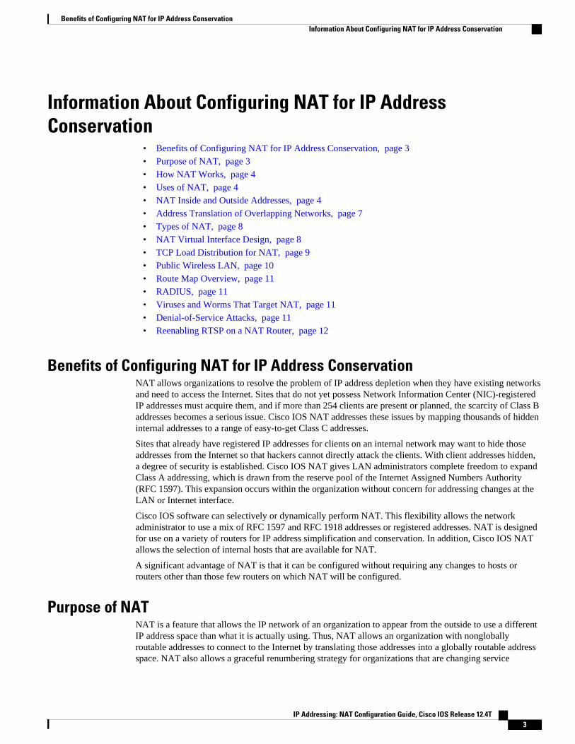
Benefits of Configuring NAT for IP Address Conservation 3
Purpose of NAT 3
How NAT Works 4
Uses of NAT 4
NAT Inside and Outside Addresses 4
Inside Source Address Translation 5
Inside Global Addresses Overloading 6
Address Translation of Overlapping Networks 7
Types of NAT 8
NAT Virtual Interface Design 8
TCP Load Distribution for NAT 9
Public Wireless LAN 10
Route Map Overview 11
RADIUS 11
Viruses and Worms That Target NAT 11
Denial-of-Service Attacks 11
Reenabling RTSP on a NAT Router 12
How to Configure NAT for IP Address Conservation 12
Configuring Inside Source Addresses 12
Configuring Static Translation of Inside Source Addresses 12
Configuring Dynamic Translation of Inside Source Addresses 15
Using NAT to Allow Internal Users Access to the Internet 17
IP Addressing: NAT Configuration Guide, Cisco IOS Release 12.4T iii

Configuring Address Translation Timeouts 19
Changing the Translation Timeout 19
Changing the Timeouts When Overloading Is Configured 20
Allowing Overlapping Networks to Communicate Using NAT 21
Configuring Static Translation of Overlapping Networks 22
Configuring Dynamic Translation of Overlapping Networks 24
Configuring the NAT Virtual Interface 26
Restrictions for NAT Virtual Interface 26
Enabling a Dynamic NAT Virtual Interface 26
Enabling a Static NAT Virtual Interface 28
Configuring Server TCP Load Balancing 29
Enabling Route Maps on Inside Interfaces 32
Enabling NAT Route Maps Outside-to-Inside Support 33
Configuring NAT of External IP Addresses Only 34
Configuring the NAT Inside Server Feature 37
Configuring Support for Users with Static IP Addresses 38
Configuring Support for ARP Ping 41
Configuring the Rate Limiting NAT Translation Feature 42
Configuration Examples for Configuring NAT for IP Address Conservation 43
Example: Configuring Static Translation of Inside Source Addresses 44
Example: Configuring Dynamic Translation of Inside Source Addresses 44
Example: Allowing Internal Users Access to the Internet 45
Example: Allowing Overlapping Networks to Communicate Using NAT 45
Example: Configuring the NAT Virtual Interface 46
Example: Configuring Server TCP Load Balancing 46
Example: Enabling Route Maps on Inside Interfaces 46
Example: Enabling NAT Route Maps Outside-to-Inside Support 46
Example: Configuring NAT Translation of External IP Addresses Only 47
Example: Configuring Support for Users with Static IP Addresses 47
Example: Configuring the Rate Limiting NAT Translation Feature 47
Where to Go Next 47
Additional References 48
Feature Information for Configuring NAT for IP Address Conservation 49
Using Application Level Gateways with NAT 53
Finding Feature Information 53
Contents
IP Addressing: NAT Configuration Guide, Cisco IOS Release 12.4Tiv

Prerequisites for Using Application Level Gateways with NAT 53
Restrictions for Using Application Level Gateways with NAT 54
Information About Using Application Level Gateways with NAT 54
Application Level Gateway 54
IP Security 55
Voice and Multimedia over IP Networks 55
NAT Support of H.323 v2 RAS 56
NAT Support for H.323 v3 and v4 in v2 Compatibility Mode 56
NAT H.245 Tunneling Support 56
NAT Support of Skinny Client Control Protocol 56
NAT Support of SCCP Fragmentation 57
NAT Segmentation with Layer 4 Forwarding 57
How to Configure Application Level Gateways with NAT 58
Configuring IPsec Through NAT 58
Configuring IPsec ESP Through NAT 58
Enabling the Preserve Port 59
Enabling SPI Matching on the NAT Device 60
Enabling SPI Matching on the Endpoints 61
Enabling MultiPart SDP Support for NAT 62
Configuring NAT Between an IP Phone and Cisco CallManager 63
Configuration Examples for Using Application Level Gateways with NAT 64
Example Configuring IPsec ESP Through NAT 64
Example Enabling the Preserve Port 65
Example Enabling SPI Matching 65
Example: Enabling SPI Matching on Endpoint Routers 65
Example Enabling MultiPart SDP Support for NAT 65
Example: Configuring NAT Between an IP Phone and Cisco CallManager 65
Where to Go Next 65
Additional References 65
Feature Information for Using Application Level Gateways with NAT 66
Configuring NAT for High Availability 69
Finding Feature Information 69
Prerequisites for Configuring NAT for High Availability 69
Restrictions for Configuring NAT for High Availability 70
Information About Configuring NAT for High Availability 70
Contents
IP Addressing: NAT Configuration Guide, Cisco IOS Release 12.4T v

Stateful NAT 70
NAT Stateful Failover for Asymmetric Outside-to-Inside ALG Support 70
Interaction with HSRP 70
Translation Group 71
Address Resolution with ARP 71
Stateful Failover for Asymmetric Outside-to-Inside Support 71
Stateful Failover for ALGs 72
How to Configure NAT for High Availability 73
Configuring the Stateful Failover of NAT 73
Restrictions for Configuring Stateful Failover of NAT 73
Configuring SNAT with HSRP 73
Configuring SNAT on the Primary (Active) Router 75
Configuring SNAT on the Backup (Standby) Router 77
Configuring NAT Stateful Failover for Asymmetric Outside-to-Inside and ALG Support 78
Prerequisites for Configuring the NAT Stateful Failover for Asymmetric Outside-to-
Inside and ALG Support Feature 79
Configuring SNAT with HSRP 79
Configuring SNAT Primary Backup 81
Configuring NAT Static Mapping Support for HSRP 83
Restrictions for Configuring Static Mapping Support for HSRP 83
Enabling HSRP on the NAT Interface 83
What to Do Next 85
Enabling Static NAT in an HSRP Environment 85
Configuration Example for NAT for High Availability 87
Examples Configuring Stateful NAT 87
Configuration Examples for NAT Stateful Failover for Asymmetric Outside-to-Inside and
ALG Support 87
Example Configuring SNAT with HSRP 87
Example Configuring SNAT Primary Backup 88
Examples Configuring Static NAT in an HSRP Environment 88
Additional References 89
Feature Information for Configuring NAT for High Availability 90
Scalability for Stateful NAT 93
Finding Feature Information 93
Restrictions for the Scalability for Stateful NAT Feature 93
Contents
IP Addressing: NAT Configuration Guide, Cisco IOS Release 12.4Tvi

Information About Scalability for Stateful NAT 93
SNAT Feature Design 94
Benefits of SNAT Scalability 94
How to Configure SNAT in HSRP Mode 94
Configuring SNAT in HSRP Mode 94
Configuration Examples for SNAT in HSRP Mode 96
Configuring SNAT in HSRP Mode Example 96
Additional References 97
Feature Information for Scalability for Stateful NAT 98
Integrating NAT with MPLS VPNs 99
Finding Feature Information 99
Prerequisites for Integrating NAT with MPLS VPNs 99
Restrictions for Integrating NAT with MPLS VPNs 100
Information About Integrating NAT with MPLS VPNs 100
Benefits of NAT Integration with MPLS VPNs 100
Implementation Options for Integrating Nat with MPLS VPNs 100
Scenarios for Implementing NAT on the PE Router 100
How to Integrate NAT with MPLS VPNs 101
Configuring Inside Dynamic NAT with MPLS VPNs 101
Configuring Inside Static NAT with MPLS VPNs 103
Configuring Outside Dynamic NAT with MPLS VPNs 105
Configuring Outside Static NAT with MPLS VPNs 106
Configuration Examples for Integrating NAT with MPLS VPNs 108
Configuring Inside Dynamic NAT with MPLS VPNs Example 108
Configuring Inside Static NAT with MPLS VPNs Example 108
Configuring Outside Dynamic NAT with MPLS VPNs Example 109
Configuring Outside Static NAT with MPLS VPNs Example 109
Where to Go Next 109
Additional References 109
Feature Information for Integrating NAT with MPLS VPNs 111
Configuring Hosted NAT Traversal for Session Border Controller 113
Finding Feature Information 113
Prerequisites for Configuring Cisco IOS Hosted NAT Traversal for Session Border Controller 114
Restrictions for Configuring Cisco IOS Hosted NAT Traversal for Session Border Controller 114
Information About Configuring Cisco IOS Hosted NAT Traversal for Session Border Controller 114
Contents
IP Addressing: NAT Configuration Guide, Cisco IOS Release 12.4T vii

Voice and Multimedia over IP Networks 114
Cisco IOS Hosted NAT Traversal for Session Border Controller Overview 115
How to Configure Cisco IOS Hosted NAT for Session Border Controller 116
Configuring Cisco IOS Hosted NAT for Session Border Controller 116
Configuration Examples for Configuring Cisco IOS Hosted NAT for Session Border
Controller 121
Example Configuring Cisco IOS Hosted NAT Traversal for Session Border Controller 121
Additional References 122
Feature Information for Configuring Hosted NAT Traversal for Session Border Controller 123
User Defined Source Port Ranges for PAT 125
Finding Feature Information 125
Restrictions for User Defined Source Port Ranges for PAT 125
Information About User Defined Source Port Ranges for PAT 125
User Defined Source Port Ranges for PAT Overview 126
Even Port Parity 126
How to Configure User Defined Source Port Ranges for PAT 126
Configuring Source Port Ranges for PAT 126
Configuring Even Port Parity 127
Configuration Examples for User Defined Source Port Ranges for PAT 128
Example User Defined Source Port Ranges for PAT 128
Example Even Port Parity 129
Additional References 129
Feature Information for User Defined Source Port Ranges for PAT 130
FPG Endpoint Agnostic Port Allocation 133
Finding Feature Information 133
Information About Endpoint Agnostic Port Allocation 133
How to Configure Endpoint Agnostic Port Allocation 134
Configuring Endpoint Agnostic Port Allocation 134
Verifying Endpoint Agnostic Port Support 136
Configuration Examples for Endpoint Agnostic Port Allocation 136
Configuring Endpoint Allocation Example 136
Additional References 137
Feature Information for Endpoint Agnostic Port Allocation 138
NAT Optimized SIP Media Path Without SDP 139
Finding Feature Information 139
Information About the NAT Optimized SIP Media Path Without SDP Feature 139
Contents
IP Addressing: NAT Configuration Guide, Cisco IOS Release 12.4Tviii

Benefits of NAT Optimized SIP Media Path Without SDP 139
NAT Optimized SIP Media Path Without SDP Feature Design 140
How to Configure NAT Optimized SIP Media Path Without SDP 140
Configuring a NAT Optimized SIP Media Path Without SDP Messages Including MD5
Authentication 140
Configuring a NAT Optimized SIP Media Path Without SDP Messages 141
Configuration Examples for NAT Optimized SIP Media Path Without SDP 142
Configuring a NAT Optimized SIP Media Path Without SDP Including MD5 Authentication
Example 142
Configuring a NAT Optimized SIP Media Path Without SDP or MD5 Authentication Example 142
Additional References 142
Feature Information for NAT Optimized SIP Media Path Without SDP 143
NAT Optimized SIP Media Path with SDP 145
Finding Feature Information 145
Information About the NAT Optimized SIP Media Path with SDP Feature 145
Restrictions for NAT Optimized SIP Media Path with SDP 145
Benefits of NAT Optimized SIP Media Path with SDP 146
NAT Optimized SIP Media Path with SDP Feature Design 146
How to Configure NAT Optimized SIP Media Path with SDP 146
Configuring a NAT Optimized SIP Media Path with SDP Messages Including MD5
Authentication 146
Configuring a NAT Optimized SIP Media Path with SDP Messages Without MD5
Authentication 147
Configuration Examples for NAT Optimized SIP Media Path with SDP 148
Configuring a NAT Optimized SIP Media Path with SDP Including MD5 Authentication
Example 148
Configuring a NAT Optimized SIP Media Path with SDP Without MD5 Authentication
Example 148
Additional References 148
Feature Information for NAT Optimized SIP Media Path with SDP 150
Monitoring and Maintaining NAT 151
Finding Feature Information 151
Prerequisites for Monitoring and Maintaining NAT 151
Information About Monitoring and Maintaining NAT 151
NAT Display Contents 152
Translation Entries 152
Contents
IP Addressing: NAT Configuration Guide, Cisco IOS Release 12.4T ix

Statistical Information 152
Syslog Usage 153
How to Monitor and Maintain NAT 153
Displaying NAT Translation Information 153
Examples 154
Clearing NAT Entries Before the Timeout 155
Enabling Syslog for Logging NAT Translations 157
Examples for Monitoring and Maintaining NAT 158
Clearing UDP NAT Translations Example 158
Enabling Syslog Example 158
Where to Go Next 159
Additional References 159
Feature Information for Monitoring and Maintaining NAT 160
Contents
IP Addressing: NAT Configuration Guide, Cisco IOS Release 12.4Tx

Configuring NAT for IP Address Conservation
This module describes how to configure Network Address Translation (NAT) for IP address conservationand configure inside and outside source addresses. This module also provides information about thebenefits of configuring NAT for IP address conservation.
NAT enables private IP internetworks that use nonregistered IP addresses to connect to the Internet. NAToperates on a router, usually connecting two networks, and translates the private (not globally unique)addresses in the internal network into legal addresses before packets are forwarded onto another network.NAT can be configured to advertise only one address for the entire network to the outside world. Thisability provides additional security by effectively hiding the entire internal network behind that oneaddress.
NAT is also used at the enterprise edge to allow internal users access to the Internet and to allow Internetaccess to internal devices such as mail servers.
• Finding Feature Information, page 1• Prerequisites for Configuring NAT for IP Address Conservation, page 1• Restrictions for Configuring NAT for IP Address Conservation, page 2• Information About Configuring NAT for IP Address Conservation, page 3• How to Configure NAT for IP Address Conservation, page 12• Configuration Examples for Configuring NAT for IP Address Conservation, page 43• Where to Go Next, page 47• Additional References, page 48• Feature Information for Configuring NAT for IP Address Conservation, page 49
Finding Feature InformationYour software release may not support all the features documented in this module. For the latest featureinformation and caveats, see the release notes for your platform and software release. To find informationabout the features documented in this module, and to see a list of the releases in which each feature issupported, see the Feature Information Table at the end of this document.
Use Cisco Feature Navigator to find information about platform support and Cisco software image support.To access Cisco Feature Navigator, go to www.cisco.com/go/cfn. An account on Cisco.com is not required.
Prerequisites for Configuring NAT for IP AddressConservation
• Access Lists, page 2
IP Addressing: NAT Configuration Guide, Cisco IOS Release 12.4T 1

• NAT Requirements, Objectives, and Interfaces, page 2
Access ListsAll access lists required for use with the tasks in this module should be configured prior to beginning theconfiguration task. For information about how to configure an access list, refer to the IP Access ListSequence Numbering document.
Note If you specify an access list with a NAT command, NAT will not support the commonly used permit ipany any command in the access list.
NAT Requirements, Objectives, and InterfacesBefore configuring NAT in your network, you should know on which interfaces NAT will be configuredand for what purposes. The following requirements listed will help you to decide how to configure and useNAT:
1 Define the NAT inside and outside interfaces if:
• Users exist off multiple interfaces.• Multiple interfaces connect to the Internet.
2 Define what you need NAT to accomplish:
• Allow internal users to access the Internet.• Allow the Internet to access internal devices such as a mail server.• Allow overlapping networks to communicate.• Allow networks with different address schemes to communicate.• Allow the use of an application level gateway.• Redirect TCP traffic to another TCP port or address.• Use NAT during a network transition.
Restrictions for Configuring NAT for IP Address Conservation• NAT is not practical if large numbers of hosts in the stub domain communicate outside of the domain.• Some applications use embedded IP addresses in such a way that translation by a NAT device is
impractical. These applications may not work transparently or not work at all through a NAT device.• NAT hides the identity of hosts, which may be an advantage or a disadvantage depending on the
desired result.• A router configured with NAT must not advertise the local networks to the outside. However, routing
information that NAT receives from the outside can be advertised in the stub domain as usual.• If you specify an access list with a NAT command, NAT will not support the commonly used permit
ip any any command in the access list.• NAT configuration is not supported on the access side of the Intelligent Services Gateway (ISG).
Access Lists Restrictions for Configuring NAT for IP Address Conservation
IP Addressing: NAT Configuration Guide, Cisco IOS Release 12.4T2
Information About Configuring NAT for IP AddressConservation
• Benefits of Configuring NAT for IP Address Conservation, page 3• Purpose of NAT, page 3• How NAT Works, page 4• Uses of NAT, page 4• NAT Inside and Outside Addresses, page 4• Address Translation of Overlapping Networks, page 7• Types of NAT, page 8• NAT Virtual Interface Design, page 8• TCP Load Distribution for NAT, page 9• Public Wireless LAN, page 10• Route Map Overview, page 11• RADIUS, page 11• Viruses and Worms That Target NAT, page 11• Denial-of-Service Attacks, page 11• Reenabling RTSP on a NAT Router, page 12
Benefits of Configuring NAT for IP Address ConservationNAT allows organizations to resolve the problem of IP address depletion when they have existing networksand need to access the Internet. Sites that do not yet possess Network Information Center (NIC)-registeredIP addresses must acquire them, and if more than 254 clients are present or planned, the scarcity of Class Baddresses becomes a serious issue. Cisco IOS NAT addresses these issues by mapping thousands of hiddeninternal addresses to a range of easy-to-get Class C addresses.
Sites that already have registered IP addresses for clients on an internal network may want to hide thoseaddresses from the Internet so that hackers cannot directly attack the clients. With client addresses hidden,a degree of security is established. Cisco IOS NAT gives LAN administrators complete freedom to expandClass A addressing, which is drawn from the reserve pool of the Internet Assigned Numbers Authority(RFC 1597). This expansion occurs within the organization without concern for addressing changes at theLAN or Internet interface.
Cisco IOS software can selectively or dynamically perform NAT. This flexibility allows the networkadministrator to use a mix of RFC 1597 and RFC 1918 addresses or registered addresses. NAT is designedfor use on a variety of routers for IP address simplification and conservation. In addition, Cisco IOS NATallows the selection of internal hosts that are available for NAT.
A significant advantage of NAT is that it can be configured without requiring any changes to hosts orrouters other than those few routers on which NAT will be configured.
Purpose of NATNAT is a feature that allows the IP network of an organization to appear from the outside to use a differentIP address space than what it is actually using. Thus, NAT allows an organization with nongloballyroutable addresses to connect to the Internet by translating those addresses into a globally routable addressspace. NAT also allows a graceful renumbering strategy for organizations that are changing service
Benefits of Configuring NAT for IP Address ConservationInformation About Configuring NAT for IP Address Conservation
IP Addressing: NAT Configuration Guide, Cisco IOS Release 12.4T 3

providers or voluntarily renumbering into classless interdomain routing (CIDR) blocks. NAT is describedin RFC 1631.
Beginning with Cisco IOS Release 12.1(5)T, NAT supports all H.225 and H.245 message types, includingFastConnect and Alerting as part of the H.323 Version 2 specification. Any product that makes use of thesemessage types will be able to pass through a Cisco IOS NAT configuration without any staticconfiguration. Full support for NetMeeting Directory (Internet Locator Service) is also provided throughCisco IOS NAT.
How NAT WorksA router configured with NAT will have at least one interface to the inside network and one to the outsidenetwork. In a typical environment, NAT is configured at the exit router between a stub domain and thebackbone. When a packet leaves the domain, NAT translates the locally significant source address into aglobally unique address. When a packet enters the domain, NAT translates the globally unique destinationaddress into a local address. If more than one exit point exists, each NAT must have the same translationtable. If NAT cannot allocate an address because it has run out of addresses, it drops the packet and sendsan Internet Control Message Protocol (ICMP) host unreachable packet.
Uses of NATNAT can be used for the following applications:
• When you want to connect to the Internet, but not all of your hosts have globally unique IP addresses.NAT enables private IP internetworks that use nonregistered IP addresses to connect to the Internet.NAT is configured on the router at the border of a stub domain (referred to as the inside network) anda public network such as the Internet (referred to as the outside network). NAT translates the internallocal addresses to globally unique IP addresses before sending packets to the outside network. As asolution to the connectivity problem, NAT is practical only when relatively few hosts in a stub domaincommunicate outside of the domain at the same time. When this is the case, only a small subset of theIP addresses in the domain must be translated into globally unique IP addresses when outsidecommunication is necessary, and these addresses can be reused when no longer in use.
• When you must change your internal addresses. Instead of changing the internal addresses, which canbe a considerable amount of work, you can translate them by using NAT.
• When you want to do basic load sharing of TCP traffic. You can map a single global IP address tomany local IP addresses by using the TCP load distribution feature.
NAT Inside and Outside AddressesThe term inside in a NAT context refers to networks owned by an organization that must be translated.When NAT is configured, hosts within this network will have addresses in one space (known as the localaddress space) that will appear to those outside the network as being in another space (known as the globaladdress space).
Similarly, the term outside refers to those networks to which the stub network connects, and which aregenerally not under the control of the organization. Hosts in outside networks can also be subject totranslation, and thus have local and global addresses.
NAT uses the following definitions:
• Inside local address--The IP address that is assigned to a host on the inside network. The address isprobably not a legitimate IP address assigned by the NIC or service provider.
• Inside global address--A legitimate IP address (assigned by the NIC or service provider) thatrepresents one or more inside local IP addresses to the outside world.
How NAT Works Information About Configuring NAT for IP Address Conservation
IP Addressing: NAT Configuration Guide, Cisco IOS Release 12.4T4
• Outside local address--The IP address of an outside host as it appears to the inside network. Notnecessarily a legitimate address, it is allocated from the address space routable on the inside.
• Outside global address--The IP address assigned to a host on the outside network by the owner of thehost. The address is allocated from a globally routable address or network space.
This section describes the following topics:
• Inside Source Address Translation, page 5
• Inside Global Addresses Overloading, page 6
Inside Source Address TranslationYou can translate your own IP addresses into globally unique IP addresses when communicating outside ofyour network. You can configure static or dynamic inside source translation as follows:
• Static translation establishes a one-to-one mapping between your inside local address and an insideglobal address. Static translation is useful when a host on the inside must be accessible by a fixedaddress from the outside.
• Dynamic translation establishes a mapping between an inside local address and a pool of globaladdresses.
In Cisco IOS Release 15.1(3)T and later releases, when you configure the traceroute command, NATreturns the same inside global IP address for all inside local IP addresses.
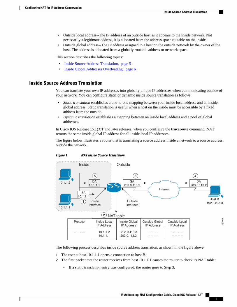
The figure below illustrates a router that is translating a source address inside a network to a source addressoutside the network.
Figure 1 NAT Inside Source Translation
10.1.1.2
Host B
192.0.2.223
10.1.1.1
Internet
Inside
Inside
interface
Outside
interface
Outside
10.1.1.2
10.1.1.1
-- -- -- -- -- -- -- --
-- -- -- --
-- -- -- --
-- -- -- --
203.0.113.3
203.0.113.2
Inside Local
IP Address
Outside Global
IP Address
Outside Local
IP Address
Protocol
NAT table
Inside Global
IP Address 12
70
11
SA
203.0.113.2
DA
10.1.1.1
SA
10.1.1.1
DA
203.0.113.2
3 45
1
2
The following process describes inside source address translation, as shown in the figure above:
1 The user at host 10.1.1.1 opens a connection to host B.2 The first packet that the router receives from host 10.1.1.1 causes the router to check its NAT table:
• If a static translation entry was configured, the router goes to Step 3.
Configuring NAT for IP Address ConservationInside Source Address Translation
IP Addressing: NAT Configuration Guide, Cisco IOS Release 12.4T 5

• If no translation entry exists, the router determines that the source address (SA) 10.1.1.1 must betranslated dynamically, selects a legal, global address from the dynamic address pool, and creates atranslation entry. This type of entry is called a simple entry.
3 The router replaces the inside local source address of host 10.1.1.1 with the global address of thetranslation entry and forwards the packet.
4 Host B receives the packet and responds to host 10.1.1.1 by using the inside global IP destinationaddress (DA) 203.0.113.2.
5 When the router receives the packet with the inside global IP address, it performs a NAT table lookupby using the inside global address as a key. It then translates the address to the inside local address ofhost 10.1.1.1 and forwards the packet to host 10.1.1.1.
Host 10.1.1.1 receives the packet and continues the conversation. The router performs Steps 2 to 5 for eachpacket.
Inside Global Addresses OverloadingYou can conserve addresses in the inside global address pool by allowing the router to use one globaladdress for many local addresses. When this overloading is configured, the router maintains enoughinformation from higher-level protocols (for example, TCP or UDP port numbers) to translate the globaladdress back to the correct local address. When multiple local addresses map to one global address, theTCP or UDP port numbers of each inside host distinguish between the local addresses.
The figure below illustrates NAT operation when one inside global address represents multiple inside localaddresses. The TCP port numbers act as differentiators.
Figure 2 NAT Overloading Inside Global Addresses
10.1.1.2:1723
10.1.1.1:1024
203.0.113.2:1723
203.0.113.2:1024
Inside Local IP
address:port
TCP
TCP
Protocol Inside Global IP
address:port
198.51.100.4:23
192.0.2.223:23
Outside Global
IP address:port
198.51.100.4:23
192.0.2.223:23
Outside Local
IP address
10.1.1.2
Inside Outside
NAT table
SA
203.0.113.2
DA
10.1.1.1
10.1.1.1
DA
203.0.113.2
DA
203.0.113.2
Host B
192.0.2.223
Host C
198.51.100.41
27
01
2
SA
10.1.1.1
Internet
3
4
4
5
1
2
The router performs the following process in overloading inside global addresses, as shown in the figureabove. Both host B and host C believe that they are communicating with a single host at address203.0.113.2. They are actually communicating with different hosts; the port number is the differentiator. Infact, many inside hosts could share the inside global IP address by using many port numbers.
1 The user at host 10.1.1.1 opens a connection to host B.2 The first packet that the router receives from host 10.1.1.1 causes the router to check its NAT table:
Configuring NAT for IP Address Conservation Inside Global Addresses Overloading
IP Addressing: NAT Configuration Guide, Cisco IOS Release 12.4T6
• If no translation entry exists, the router determines that the address 10.1.1.1 must be translated, andsets up a translation of the inside local address 10.1.1.1 to a legal global address.
• If overloading is enabled, and another translation is active, the router reuses the global addressfrom that translation and saves enough information to be able to translate the global address back.This type of entry is called an extended entry.
3 The router replaces the inside local source address 10.1.1.1 with the selected global address andforwards the packet.
4 Host B receives the packet and responds to host 10.1.1.1 by using the inside global IP address203.0.113.2.
5 When the router receives the packet with the inside global IP address, it performs a NAT table lookup,using the protocol, the inside global address and port, and the outside address and port as keys;translates the address to the inside local address 10.1.1.1; and forwards the packet to host 10.1.1.1.
Host 10.1.1.1 receives the packet and continues the conversation. The router performs Steps 2 to 5 for eachpacket.
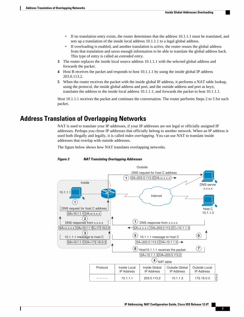
Address Translation of Overlapping NetworksNAT is used to translate your IP addresses, if your IP addresses are not legal or officially assigned IPaddresses. Perhaps you chose IP addresses that officially belong to another network. When an IP address isused both illegally and legally, it is called index overlapping. You can use NAT to translate insideaddresses that overlap with outside addresses.
The figure below shows how NAT translates overlapping networks.
Figure 3 NAT Translating Overlapping Addresses
10.1.1.1
Inside
Outside
DNS request for host C address
SA=10.1.1.1 DA=x.x.x.x
DNS server
x.x.x.x
203.0.113.2 10.1.1.3
Inside Global
IP Address
NAT table
Outside Global
IP Address
172.16.0.3
Outside Local
IP Address
Host C
10.1.1.3
12
70
13
Internet
10.1.1.1
Inside Local
IP Address
-- -- -- --
Protocol
DNS request for host C address
SA=203.0.113.2 DA=x.x.x.x
DNS response from x.x.x.x
SA=x.x.x.x DA=10.1.1.1C=172.16.0.3
10.1.1.1 message to host C
SA=10.1.1.1 DA=172.16.0.3
DNS response from x.x.x.x
SA=x.x.x.x DA=203.0.113.2 C=10.1.1.3
10.1.1.1 message to host C
SA=203.0.113.2 DA=10.1.1.3
1
2
3
1
Host10.1.1.1 receives the packet
SA=10.1.1.3 DA=203.0.113.2
8
5
4
6
7
1
Address Translation of Overlapping NetworksInside Global Addresses Overloading
IP Addressing: NAT Configuration Guide, Cisco IOS Release 12.4T 7

The router translates overlapping addresses as follows:
1 The user at host 10.1.1.1 opens a connection to host C by name, requesting a name-to-address lookupfrom a Domain Name System (DNS) server.
2 The router intercepts the DNS reply and translates the returned address if there is an overlap (that is, theresulting legal address resides illegally in the inside network). To translate the return address, the routercreates a simple translation entry mapping the overlapping address 10.1.1.3 to an address from aseparately configured, outside local address pool.
The router examines every DNS reply, ensuring that the IP address is not in the stub network. If it is, therouter translates the address as follows:
1 Host 10.1.1.1 opens a connection to 172.16.0.3.2 The router sets up translations mapping of the inside local and global addresses to each other and the
outside global and local addresses to each other.3 The router replaces the SA with the inside global address and replaces the DA with the outside global
address.4 Host C receives the packet and continues the conversation.5 The router does a lookup, replaces the DA with the inside local address, and replaces the SA with the
outside local address.6 Host 10.1.1.1 receives the packet and the conversation continues using this translation process.
Types of NATNAT operates on a router--generally connecting only two networks--and translates the private (inside local)addresses within the internal network into public (inside global) addresses before any packets areforwarded to another network. This functionality gives you the option to configure NAT so that it willadvertise only a single address for your entire network to the outside world. Doing this effectively hides theinternal network from the world, giving you some additional security.
NAT types include:
• Static address translation (static NAT)--allows one-to-one mapping between local and globaladdresses.
• Dynamic address translation (dynamic NAT)--maps unregistered IP addresses to registered IPaddresses from a pool of registered IP addresses.
• Overloading--a form of dynamic NAT that maps multiple unregistered IP addresses to a singleregistered IP address (many to one) using different ports. This method is also known as Port AddressTranslation (PAT). By using PAT (NAT overload), thousands of users can be connected to the Internetusing only one real global IP address.
NAT Virtual Interface DesignThe NAT Virtual Interface (NVI) feature allows NAT traffic flows on the virtual interface, eliminating theneed to specify inside and outside domains. When a domain is specified, translation rules are applied eitherbefore or after the route decisions, depending on the traffic flow from inside to outside or outside to inside.The translation rules are applied only after the route decision for an NVI.
When a NAT pool is shared for translating packets from multiple networks connected to a NAT router, anNVI is created and a static route is configured that forwards all packets addressed to the NAT pool to theNVI. The standard interfaces connected to various networks will be configured to identify that the trafficoriginating from and received on the interfaces needs to be translated.
Types of NAT Inside Global Addresses Overloading
IP Addressing: NAT Configuration Guide, Cisco IOS Release 12.4T8
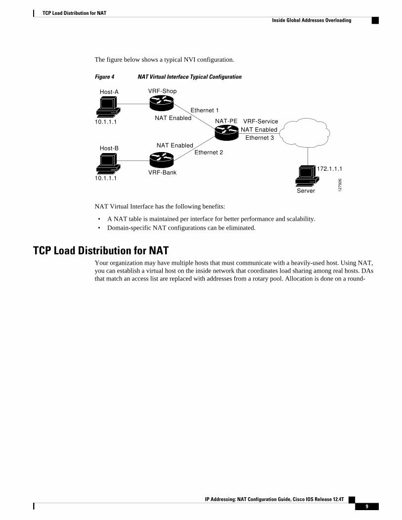
The figure below shows a typical NVI configuration.
Figure 4 NAT Virtual Interface Typical Configuration
Host-A
Host-B
10.1.1.1
10.1.1.1
Ethernet 1
Ethernet 2
Server
172.1.1.1
Ethernet 3
NAT-PE VRF-ServiceNAT Enabled
NAT Enabled
NAT Enabled
VRF-Shop
VRF-Bank
127926
NAT Virtual Interface has the following benefits:
• A NAT table is maintained per interface for better performance and scalability.• Domain-specific NAT configurations can be eliminated.
TCP Load Distribution for NATYour organization may have multiple hosts that must communicate with a heavily-used host. Using NAT,you can establish a virtual host on the inside network that coordinates load sharing among real hosts. DAsthat match an access list are replaced with addresses from a rotary pool. Allocation is done on a round-
TCP Load Distribution for NATInside Global Addresses Overloading
IP Addressing: NAT Configuration Guide, Cisco IOS Release 12.4T 9

robin basis, and only when a new connection is opened from the outside to the inside. Non-TCP traffic ispassed untranslated (unless other translations are in effect). The figure below illustrates this feature.
Figure 5 NAT TCP Load Distribution
NAT table
12
70
14
Intranet
Outside
192.0.2.223
B
C
198.51.100.4
DA
10.1.1.127
1
SA
10.1.1.127
5
SA
10.1.1.1
Inside
10.1.1.1
Real
hosts
Virtual
host
10.1.1.2
10.1.1.3
10.1.1.127
DA
10.1.1.1
4
3
2
10.1.1.1:23
10.1.1.2:23
10.1.1.3:23
10.1.1.127:23
10.1.1.127:23
10.1.1.127:23
Inside Local IP
address:port
TCP
TCP
TCP
ProtocolInside Global IP
address:port
192.0.2.225:3058
198.51.100.4
192.0.2.223:3062
Outside Global
IP address:port
192.0.2.225:3058
198.51.100.4:4371
192.0.2.223:3062
Outside Local
IP address
The router performs the following process when translating rotary addresses:
1 The user on host B (192.0.2.223) opens a connection to the virtual host at 10.1.1.127.2 The router receives the connection request and creates a new translation, allocating the next real host
(10.1.1.1) for the inside local IP address.3 The router replaces the destination address with the selected real host address and forwards the packet.4 Host 10.1.1.1 receives the packet and responds.5 The router receives the packet and performs a NAT table lookup using the inside local address and port
number, and the outside address and port number as the key. The router then translates the sourceaddress to the address of the virtual host and forwards the packet.
6 The next connection request will cause the router to allocate 10.1.1.2 for the inside local address.
Public Wireless LANA public wireless LAN provides users of mobile computing devices with wireless connections to a publicnetwork, such as the Internet.
Public Wireless LAN Inside Global Addresses Overloading
IP Addressing: NAT Configuration Guide, Cisco IOS Release 12.4T10

Route Map OverviewFor NAT, a route map must be processed instead of an access list. A route map allows you to match anycombination of access list, next-hop IP address, and output interface to determine which pool to use. Theability to use route maps with static translations enables the NAT multihoming capability with staticaddress translations. Multihomed internal networks can host common services such as the Internet andDNS, which are accessed from different outside networks. NAT processes route map-based mappings inlexicographical order. When static NAT and dynamic NAT are configured with route maps that share thesame name, static NAT is given precedence over dynamic NAT. In order to ensure the precedence of staticNAT over dynamic NAT, you can either configure the route map associated with static NAT and dynamicNAT to share the same name, or configure the static NAT route map name so that it is lexicographicallylower than that of the dynamic NAT route map name.
Benefits of using route maps for address translation are as follows:
• The ability to configure route map statements provides the option of using IPsec with NAT.• Translation decisions can be made based on the destination IP address when static translation entries
are used.
RADIUSRADIUS is a distributed client/server system that secures networks against unauthorized access.Communication between a network access server (NAS) and a RADIUS server is based on UDP.Generally, the RADIUS protocol is considered a connectionless service. Issues related to serveravailability, retransmission, and timeouts are handled by RADIUS-enabled devices rather than thetransmission protocol.
RADIUS is a client/server protocol. The RADIUS client is typically a NAS, and the RADIUS server isusually a daemon process running on a UNIX or Windows NT machine. The client passes user informationto designated RADIUS servers and acts on the response that is returned. RADIUS servers receive userconnection requests, authenticate the user, and then return the configuration information necessary for theclient to deliver the service to the user. A RADIUS server can act as a proxy client to other RADIUSservers or other kinds of authentication servers.
Viruses and Worms That Target NATViruses and worms are malicious programs designed to attack computer and networking equipment.Although viruses are typically embedded in discrete applications and run only when executed, worms self-propagate and can quickly spread on their own. Although a specific virus or worm may not expressly targetNAT, it might use NAT resources to propagate itself. The Rate Limiting NAT Translation feature can beused to limit the impact of viruses and worms that originate from specific hosts, access control lists, andVPN routing and forwarding (VRF) instances.
Denial-of-Service AttacksA denial-of-service (DoS) attack typically involves the misuse of standard protocols or connectionprocesses with the intent to overload and disable a target, such as a router or web server. DoS attacks cancome from a malicious user or from a computer infected with a virus or worm. An attack that comes frommany different sources at once, such as when a virus or worm has infected many computers, is known as adistributed denial-of-service (DDoS) attack. Such DDoS attacks can spread rapidly and involve thousandsof systems.
Route Map OverviewInside Global Addresses Overloading
IP Addressing: NAT Configuration Guide, Cisco IOS Release 12.4T 11
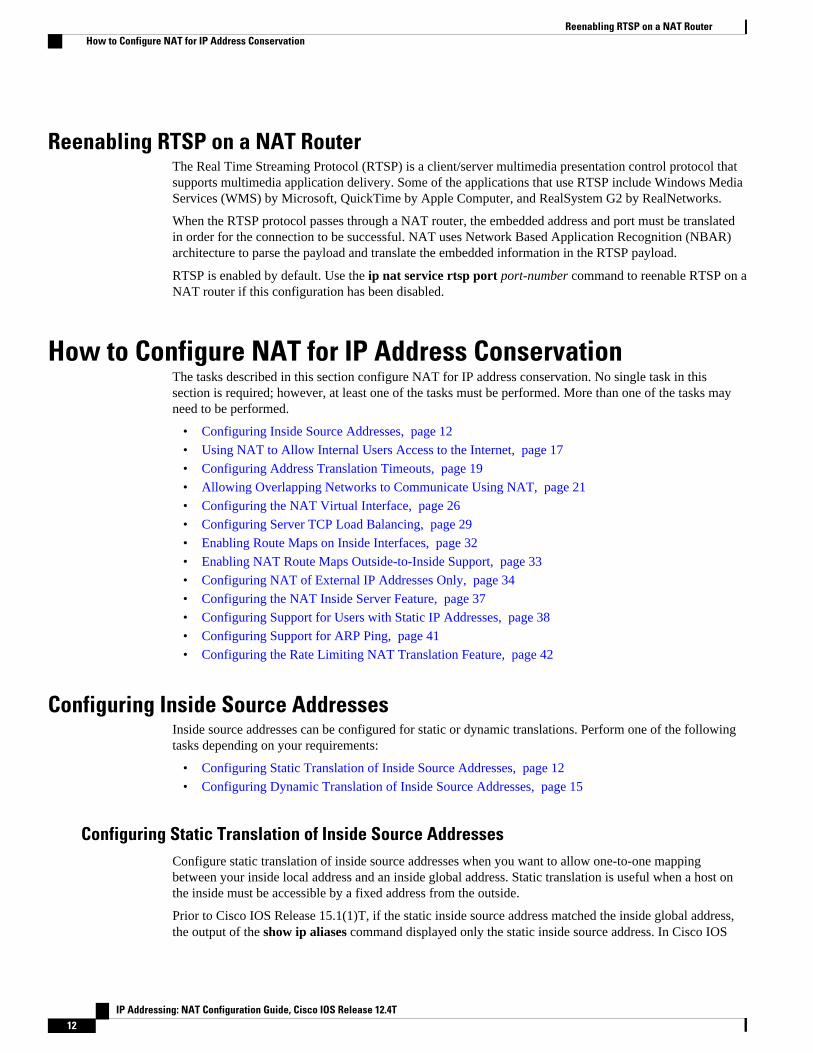
Reenabling RTSP on a NAT RouterThe Real Time Streaming Protocol (RTSP) is a client/server multimedia presentation control protocol thatsupports multimedia application delivery. Some of the applications that use RTSP include Windows MediaServices (WMS) by Microsoft, QuickTime by Apple Computer, and RealSystem G2 by RealNetworks.
When the RTSP protocol passes through a NAT router, the embedded address and port must be translatedin order for the connection to be successful. NAT uses Network Based Application Recognition (NBAR)architecture to parse the payload and translate the embedded information in the RTSP payload.
RTSP is enabled by default. Use the ip nat service rtsp port port-number command to reenable RTSP on aNAT router if this configuration has been disabled.
How to Configure NAT for IP Address ConservationThe tasks described in this section configure NAT for IP address conservation. No single task in thissection is required; however, at least one of the tasks must be performed. More than one of the tasks mayneed to be performed.
• Configuring Inside Source Addresses, page 12
• Using NAT to Allow Internal Users Access to the Internet, page 17
• Configuring Address Translation Timeouts, page 19
• Allowing Overlapping Networks to Communicate Using NAT, page 21
• Configuring the NAT Virtual Interface, page 26
• Configuring Server TCP Load Balancing, page 29
• Enabling Route Maps on Inside Interfaces, page 32
• Enabling NAT Route Maps Outside-to-Inside Support, page 33
• Configuring NAT of External IP Addresses Only, page 34
• Configuring the NAT Inside Server Feature, page 37
• Configuring Support for Users with Static IP Addresses, page 38
• Configuring Support for ARP Ping, page 41
• Configuring the Rate Limiting NAT Translation Feature, page 42
Configuring Inside Source AddressesInside source addresses can be configured for static or dynamic translations. Perform one of the followingtasks depending on your requirements:
• Configuring Static Translation of Inside Source Addresses, page 12
• Configuring Dynamic Translation of Inside Source Addresses, page 15
Configuring Static Translation of Inside Source AddressesConfigure static translation of inside source addresses when you want to allow one-to-one mappingbetween your inside local address and an inside global address. Static translation is useful when a host onthe inside must be accessible by a fixed address from the outside.
Prior to Cisco IOS Release 15.1(1)T, if the static inside source address matched the inside global address,the output of the show ip aliases command displayed only the static inside source address. In Cisco IOS
Reenabling RTSP on a NAT Router How to Configure NAT for IP Address Conservation
IP Addressing: NAT Configuration Guide, Cisco IOS Release 12.4T12

Release 15.1(1)T and later releases, if the static inside source address matches the inside global address, theoutput of the show ip aliases command displays both the addresses. The static inside source address isdisplayed as an interface address and the inside global address is displayed as a dynamic address.
Note You must configure different IP addresses for the interface on which NAT is configured and for the insideaddresses that are configured by using the ip nat inside source static command.
SUMMARY STEPS
1. enable
2. configure terminal
3. ip nat inside source static local-ip global-ip
4. interface type number
5. ip address ip-address mask [secondary]
6. ip nat inside
7. exit
8. interface type number
9. ip address ip-address mask
10. ip nat outside
11. end
DETAILED STEPS
Command or Action Purpose
Step 1 enable
Example:
Router> enable
Enables privileged EXEC mode.
• Enter your password if prompted.
Step 2 configure terminal
Example:
Router# configure terminal
Enters global configuration mode.
Step 3 ip nat inside source static local-ip global-ip
Example:
Router(config)# ip nat inside source static 10.10.10.1 172.16.131.1
Establishes static translation between an inside localaddress and an inside global address.
Configuring NAT for IP Address ConservationConfiguring Static Translation of Inside Source Addresses
IP Addressing: NAT Configuration Guide, Cisco IOS Release 12.4T 13

Command or Action Purpose
Step 4 interface type number
Example:
Router(config)# interface ethernet 1
Specifies an interface and enters interfaceconfiguration mode.
Step 5 ip address ip-address mask [secondary]
Example:
Router(config-if)# ip address 10.114.11.39 255.255.255.0
Sets a primary IP address for an interface.
Step 6 ip nat inside
Example:
Router(config-if)# ip nat inside
Marks the interface as connected to the inside.
Step 7 exit
Example:
Router(config-if)# exit
Exits interface configuration mode and returns toglobal configuration mode.
Step 8 interface type number
Example:
Router(config)# interface ethernet 0
Specifies a different interface and enters interfaceconfiguration mode.
Step 9 ip address ip-address mask
Example:
Router(config-if)# ip address 172.31.232.182 255.255.255.240
Sets a primary IP address for an interface.
Step 10 ip nat outside
Example:
Router(config-if)# ip nat outside
Marks the interface as connected to the outside.
Configuring NAT for IP Address Conservation Configuring Static Translation of Inside Source Addresses
IP Addressing: NAT Configuration Guide, Cisco IOS Release 12.4T14

Command or Action Purpose
Step 11 end
Example:
Router(config-if)# end
Exits interface configuration mode and returns toprivileged EXEC mode.
Configuring Dynamic Translation of Inside Source AddressesDynamic translation establishes a mapping between an inside local address and a pool of global addresses.Dynamic translation is useful when multiple users on a private network need to access the Internet. Thedynamically configured pool IP address may be used as needed and is released for use by other users whenaccess to the Internet is no longer required.
SUMMARY STEPS
1. enable
2. configure terminal
3. ip nat pool name start-ip end-ip {netmask netmask | prefix-length prefix-length}
4. access-list access-list-number permit source [source-wildcard]
5. ip nat inside source list access-list -number pool name
6. interface type number
7. ip address ip-address mask
8. ip nat inside
9. exit
10. interface type number
11. ip address ip-address mask
12. ip nat outside
13. end
DETAILED STEPS
Command or Action Purpose
Step 1 enable
Example:Router> enable
Enables privileged EXEC mode.
• Enter your password if prompted.
Step 2 configure terminal
Example:Router# configure terminal
Enters global configuration mode.
Configuring NAT for IP Address ConservationConfiguring Dynamic Translation of Inside Source Addresses
IP Addressing: NAT Configuration Guide, Cisco IOS Release 12.4T 15

Command or Action Purpose
Step 3 ip nat pool name start-ip end-ip {netmask netmask | prefix-length prefix-length}
Example:Router(config)# ip nat pool net-208 172.16.233.208 172.16.233.223 prefix-length 28
Defines a pool of global addresses to be allocated asneeded.
Step 4 access-list access-list-number permit source [source-wildcard]
Example:Router(config)# access-list 1 permit 192.168.34.0 0.0.0.255
Defines a standard access list permitting thoseaddresses that are to be translated.
Step 5 ip nat inside source list access-list -number pool name
Example:Router(config)# ip nat inside source list 1 pool net-208
Establishes dynamic source translation, specifyingthe access list defined in the prior step.
Step 6 interface type number
Example:Router(config)# interface ethernet 1
Specifies an interface and enters interfaceconfiguration mode.
Step 7 ip address ip-address mask
Example:Router(config-if)# ip address 10.114.11.39 255.255.255.0
Sets a primary IP address for the interface.
Step 8 ip nat inside
Example:Router(config-if)# ip nat inside
Marks the interface as connected to the inside.
Step 9 exit
Example:Router(config-if)# exit
Exits interface configuration mode and returns toglobal configuration mode.
Step 10 interface type number
Example:Router(config)# interface ethernet 0
Specifies an interface and enters interfaceconfiguration mode.
Configuring NAT for IP Address Conservation Configuring Dynamic Translation of Inside Source Addresses
IP Addressing: NAT Configuration Guide, Cisco IOS Release 12.4T16

Command or Action Purpose
Step 11 ip address ip-address mask
Example:Router(config-if)# ip address 172.16.232.182 255.255.255.240
Sets a primary IP address for the interface.
Step 12 ip nat outside
Example:Router(config-if)# ip nat outside
Marks the interface as connected to the outside.
Step 13 end
Example:Router(config-if)# end
Exits interface configuration mode and returns toprivileged EXEC mode.
Using NAT to Allow Internal Users Access to the InternetPerform this task to allow your internal users access to the Internet and conserve addresses in the insideglobal address pool using overloading of global addresses.
SUMMARY STEPS
1. enable
2. configure terminal
3. ip nat pool name start-ip end-ip {netmask netmask | prefix-length prefix-length}
4. access-list access-list-number permit source [source-wildcard]
5. ip nat inside source list access-list-number pool name overload
6. interface type number
7. ip address ip-address mask
8. ip nat inside
9. exit
10. interface type number
11. ip address ip-address mask
12. ip nat outside
13. end
Using NAT to Allow Internal Users Access to the InternetConfiguring Dynamic Translation of Inside Source Addresses
IP Addressing: NAT Configuration Guide, Cisco IOS Release 12.4T 17

DETAILED STEPS
Command or Action Purpose
Step 1 enable
Example:Router> enable
Enables privileged EXEC mode.
• Enter your password if prompted.
Step 2 configure terminal
Example:Router# configure terminal
Enters global configuration mode.
Step 3 ip nat pool name start-ip end-ip {netmask netmask |prefix-length prefix-length}
Example:Router(config)# ip nat pool net-208 192.168.202.129 192.168.202.158 netmask 255.255.255.224
Defines a pool of global addresses to be allocated asneeded.
Step 4 access-list access-list-number permit source [source-wildcard]
Example:Router(config)# access-list 1 permit 192.168.201.30 0.0.0.255
Defines a standard access list permitting those addressesthat are to be translated.
• The access list must permit only those addresses thatare to be translated. (Remember that there is an implicit“deny all” at the end of each access list.) Use of anaccess list that is too permissive can lead tounpredictable results.
Step 5 ip nat inside source list access-list-number pool nameoverload
Example:Router(config)# ip nat inside source list 1 pool net-208 overload
Establishes dynamic source translation with overloading,specifying the access list defined in Step 4.
Step 6 interface type number
Example:Router(config)# interface ethernet 1
Specifies an interface and enters interface configurationmode.
Step 7 ip address ip-address mask
Example:Router(config-if)# ip address 192.168.201.1 255.255.255.240
Sets a primary IP address for the interface.
Configuring NAT for IP Address Conservation Configuring Dynamic Translation of Inside Source Addresses
IP Addressing: NAT Configuration Guide, Cisco IOS Release 12.4T18

Command or Action Purpose
Step 8 ip nat inside
Example:Router(config-if)# ip nat inside
Marks the interface as connected to the inside.
Step 9 exit
Example:Router(config-if)# exit
Exits interface configuration mode and returns to globalconfiguration mode.
Step 10 interface type number
Example:Router(config)# interface ethernet 0
Specifies an interface and enters interface configurationmode.
Step 11 ip address ip-address mask
Example:Router(config-if)# ip address 192.168.201.29 255.255.255.240
Sets a primary IP address for the interface.
Step 12 ip nat outside
Example:Router(config-if)# ip nat outside
Marks the interface as connected to the outside.
Step 13 end
Example:Router(config-if)# end
Exits interface configuration mode and returns to privilegedEXEC mode.
Configuring Address Translation TimeoutsYou can configure address translation timeouts based on your specific configuration of NAT.
• Changing the Translation Timeout, page 19
• Changing the Timeouts When Overloading Is Configured, page 20
Changing the Translation TimeoutBy default, dynamic address translations time out after some period of nonuse. You can change the defaultvalues on timeouts, if necessary. When overloading is not configured, simple translation entries time outafter 24 hours. Configure the ip nat translation timeout seconds command to change the timeout value fordynamic address translations that do not use overloading.
Configuring Address Translation TimeoutsChanging the Translation Timeout
IP Addressing: NAT Configuration Guide, Cisco IOS Release 12.4T 19
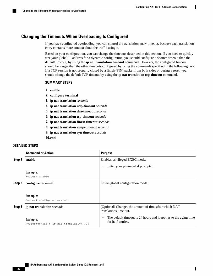
Changing the Timeouts When Overloading Is ConfiguredIf you have configured overloading, you can control the translation entry timeout, because each translationentry contains more context about the traffic using it.
Based on your configuration, you can change the timeouts described in this section. If you need to quicklyfree your global IP address for a dynamic configuration, you should configure a shorter timeout than thedefault timeout, by using the ip nat translation timeout command. However, the configured timeoutshould be longer than the other timeouts configured by using the commands specified in the following task.If a TCP session is not properly closed by a finish (FIN) packet from both sides or during a reset, youshould change the default TCP timeout by using the ip nat translation tcp-timeout command.
SUMMARY STEPS
1. enable
2. configure terminal
3. ip nat translation seconds
4. ip nat translation udp-timeout seconds
5. ip nat translation dns-timeout seconds
6. ip nat translation tcp-timeout seconds
7. ip nat translation finrst-timeout seconds
8. ip nat translation icmp-timeout seconds
9. ip nat translation syn-timeout seconds
10. end
DETAILED STEPS
Command or Action Purpose
Step 1 enable
Example:Router> enable
Enables privileged EXEC mode.
• Enter your password if prompted.
Step 2 configure terminal
Example:Router# configure terminal
Enters global configuration mode.
Step 3 ip nat translation seconds
Example:Router(config)# ip nat translation 300
(Optional) Changes the amount of time after which NATtranslations time out.
• The default timeout is 24 hours and it applies to the aging timefor half-entries.
Configuring NAT for IP Address Conservation Changing the Timeouts When Overloading Is Configured
IP Addressing: NAT Configuration Guide, Cisco IOS Release 12.4T20

Command or Action Purpose
Step 4 ip nat translation udp-timeout seconds
Example:Router(config)# ip nat translation udp-timeout 300
(Optional) Changes the UDP timeout value.
Step 5 ip nat translation dns-timeout seconds
Example:Router(config)# ip nat translation dns-timeout 45
(Optional) Changes the Domain Name System (DNS) timeoutvalue.
Step 6 ip nat translation tcp-timeout seconds
Example:Router(config)# ip nat translation tcp-timeout 2500
(Optional) Changes the TCP timeout value.
• The default is 24 hours.
Step 7 ip nat translation finrst-timeout seconds
Example:Router(config)# ip nat translation finrst-timeout 45
(Optional) Changes the finish and reset timeout value.
• finrst-timeout--The aging time after a TCP session receivesboth finish-in (FIN-IN) and finish-out (FIN-OUT) or after thereset of a TCP session.
Step 8 ip nat translation icmp-timeout seconds
Example:Router(config)# ip nat translation icmp-timeout 45
(Optional) Changes the ICMP timeout value.
Step 9 ip nat translation syn-timeout seconds
Example:Router(config)# ip nat translation syn-timeout 45
(Optional) Changes the synchronous (SYN) timeout value.
• The synchronous timeout or the aging time is used only whena SYN is received on a TCP session. When a synchronousacknowledgment (SYNACK) is received, the timeout changesto TCP timeout.
Step 10 end
Example:Router(config)# end
(Optional) Exits global configuration mode and returns toprivileged EXEC mode.
Allowing Overlapping Networks to Communicate Using NATThe tasks in this section are grouped because they perform the same action but are executed differentlydepending on the type of translation that is implemented--static or dynamic:
Allowing Overlapping Networks to Communicate Using NATChanging the Timeouts When Overloading Is Configured
IP Addressing: NAT Configuration Guide, Cisco IOS Release 12.4T 21

Perform the task that applies to the translation type that is implemented.
• Configuring Static Translation of Overlapping Networks, page 22
• Configuring Dynamic Translation of Overlapping Networks, page 24
Configuring Static Translation of Overlapping NetworksConfigure static translation of overlapping networks if your IP addresses in the stub network are legitimateIP addresses belonging to another network and you want to communicate with those hosts or routers usingstatic translation.
SUMMARY STEPS
1. enable
2. configure terminal
3. ip nat inside source static local-ip global-ip
4. interface type number
5. ip address ip-address mask
6. ip nat inside
7. exit
8. interface type number
9. ip address ip-address mask
10. ip nat outside
11. end
DETAILED STEPS
Command or Action Purpose
Step 1 enable
Example:Router> enable
Enables privileged EXEC mode.
• Enter your password if prompted.
Step 2 configure terminal
Example:Router# configure terminal
Enters global configuration mode.
Step 3 ip nat inside source static local-ip global-ip
Example:Router(config)# ip nat inside source static 192.168.121.33 10.2.2.1
Establishes static translation between an inside localaddress and an inside global address.
Configuring NAT for IP Address Conservation Configuring Static Translation of Overlapping Networks
IP Addressing: NAT Configuration Guide, Cisco IOS Release 12.4T22

Command or Action Purpose
Step 4 interface type number
Example:Router(config)# interface ethernet 1
Specifies an interface and enters interfaceconfiguration mode.
Step 5 ip address ip-address mask
Example:Router(config-if)# ip address 10.114.11.39 255.255.255.0
Sets a primary IP address for the interface.
Step 6 ip nat inside
Example:Router(config-if)# ip nat inside
Marks the interface as connected to the inside.
Step 7 exit
Example:Router(config-if)# exit
Exits interface configuration mode and returns toglobal configuration mode.
Step 8 interface type number
Example:Router(config)# interface ethernet 0
Specifies an interface and enters interfaceconfiguration mode.
Step 9 ip address ip-address mask
Example:Router(config-if)# ip address 172.16.232.182 255.255.255.240
Sets a primary IP address for the interface.
Step 10 ip nat outside
Example:Router(config-if)# ip nat outside
Marks the interface as connected to the outside.
Step 11 end
Example:Router(config-if)# end
(Optional) Exits interface configuration mode andreturns to privileged EXEC mode.
Configuring NAT for IP Address ConservationConfiguring Static Translation of Overlapping Networks
IP Addressing: NAT Configuration Guide, Cisco IOS Release 12.4T 23

Configuring Dynamic Translation of Overlapping NetworksConfigure dynamic translation of overlapping networks if your IP addresses in the stub network arelegitimate IP addresses belonging to another network and you want to communicate with those hosts orrouters using dynamic translation.
SUMMARY STEPS
1. enable
2. configure terminal
3. ip nat pool name start-ip end-ip {netmask netmask | prefix-length prefix-length}
4. access-list access-list-number permit source [source-wildcard]
5. ip nat outside source list access-list-number pool name
6. interface type number
7. ip address ip-address mask
8. ip nat inside
9. exit
10. interface type number
11. ip address ip-address mask
12. ip nat outside
13. end
DETAILED STEPS
Command or Action Purpose
Step 1 enable
Example:Router> enable
Enables privileged EXEC mode.
• Enter your password if prompted.
Step 2 configure terminal
Example:Router# configure terminal
Enters global configuration mode.
Step 3 ip nat pool name start-ip end-ip {netmask netmask |prefix-length prefix-length}
Example:Router(config)# ip nat pool net-10 10.0.1.0 10.0.1.255 prefix-length 24
Defines a pool of global addresses to be allocated as needed.
Configuring NAT for IP Address Conservation Configuring Dynamic Translation of Overlapping Networks
IP Addressing: NAT Configuration Guide, Cisco IOS Release 12.4T24

Command or Action Purpose
Step 4 access-list access-list-number permit source [source-wildcard]
Example:Router(config)# access-list 1 permit 10.114.11.0 0.0.0.255
Defines a standard access list permitting those addressesthat are to be translated.
• The access list must permit only those addresses thatare to be translated. (Remember that there is an implicit“deny all” at the end of each access list.) Use of anaccess list that is too permissive can lead tounpredictable results.
Step 5 ip nat outside source list access-list-number pool name
Example:Router(config)# ip nat outside source list 1 pool net-10
Establishes dynamic outside source translation, specifyingthe access list defined in Step 4.
Step 6 interface type number
Example:Router(config)# interface ethernet 1
Specifies an interface and enters interface configurationmode.
Step 7 ip address ip-address mask
Example:Router(config-if)# ip address 10.114.11.39 255.255.255.0
Sets a primary IP address for the interface.
Step 8 ip nat inside
Example:Router(config-if)# ip nat inside
Marks the interface as connected to the inside.
Step 9 exit
Example:Router(config-if)# exit
Exits interface configuration mode and returns to globalconfiguration mode.
Step 10 interface type number
Example:Router(config)# interface ethernet 0
Specifies an interface and enters interface configurationmode.
Configuring NAT for IP Address ConservationConfiguring Dynamic Translation of Overlapping Networks
IP Addressing: NAT Configuration Guide, Cisco IOS Release 12.4T 25

Command or Action Purpose
Step 11 ip address ip-address mask
Example:Router(config-if)# ip address 172.16.232.182 255.255.255.240
Sets a primary IP address for the interface.
Step 12 ip nat outside
Example:Router(config-if)# ip nat outside
Marks the interface as connected to the outside.
Step 13 end
Example:Router(config-if)# end
(Optional) Exits interface configuration mode and returns toprivileged EXEC mode.
Configuring the NAT Virtual InterfaceThe NAT Virtual Interface feature removes the requirement to configure an interface as either NAT insideor NAT outside. An interface can be configured to use or not use NAT.
• Restrictions for NAT Virtual Interface, page 26
• Enabling a Dynamic NAT Virtual Interface, page 26
• Enabling a Static NAT Virtual Interface, page 28
Restrictions for NAT Virtual Interface
• Route maps are not supported.• NVI is not supported in a NAT on-a-stick scenario. The term NAT on-a-stick implies the use of a
single physical interface of a router for translation. NVI is designed for traffic from one VPN routingand forwarding (VRF) instance to another and not for routing between subnets in a global routingtable. For more information on NAT on-a-stick, see http://www.cisco.com/en/US/tech/tk648/tk361/technologies_tech_note09186a0080094430.shtml.
Enabling a Dynamic NAT Virtual Interface
Configuring the NAT Virtual Interface Restrictions for NAT Virtual Interface
IP Addressing: NAT Configuration Guide, Cisco IOS Release 12.4T26

SUMMARY STEPS
1. enable
2. configure terminal
3. interface type number
4. ip nat enable
5. exit
6. ip nat pool name start-ip end-ip netmask netmask add-route
7. ip nat source list access-list-number pool number vrf name
8. ip nat source list access-list-number pool number vrf name overload
9. end
DETAILED STEPS
Command or Action Purpose
Step 1 enable
Example:Router> enable
Enables privileged EXEC mode.
• Enter your password if prompted.
Step 2 configure terminal
Example:Router# configure terminal
Enters global configuration mode.
Step 3 interface type number
Example:Router(config)# interface FastEthernet l
Configures an interface and enters interfaceconfiguration mode.
Step 4 ip nat enable
Example:Router(config-if)# ip nat enable
Configures an interface that connects VPNs andthe Internet for NAT.
Step 5 exit
Example:Router(config-if)# exit
Returns to global configuration mode.
Configuring NAT for IP Address ConservationEnabling a Dynamic NAT Virtual Interface
IP Addressing: NAT Configuration Guide, Cisco IOS Release 12.4T 27

Command or Action Purpose
Step 6 ip nat pool name start-ip end-ip netmask netmask add-route
Example:Router(config)# ip nat pool pool1 192.168.200.225 192.168.200.254 netmask 255.255.255.0 add-route
Configures a NAT pool and the associatedmappings.
Step 7 ip nat source list access-list-number pool number vrf name
Example:Router(config)# ip nat source list 1 pool pool1 vrf vrf1
Configures an NVI without an inside or outsidespecification for the specified customer.
Step 8 ip nat source list access-list-number pool number vrf name overload
Example:Router(config)# ip nat source list 1 pool 1 vrf vrf2 overload
Configures an NVI without an inside or outsidespecification for the specified customer.
Step 9 end
Example:Router(config)# end
(Optional) Exits global configuration mode andreturns to privileged EXEC mode.
Enabling a Static NAT Virtual Interface
SUMMARY STEPS
1. enable
2. configure terminal
3. interface type number
4. ip nat enable
5. exit
6. ip nat source static local-ip global-ip vrf name
7. end
DETAILED STEPS
Command or Action Purpose
Step 1 enable
Example:Router> enable
Enables privileged EXEC mode.
• Enter your password if prompted.
Configuring NAT for IP Address Conservation Enabling a Static NAT Virtual Interface
IP Addressing: NAT Configuration Guide, Cisco IOS Release 12.4T28

Command or Action Purpose
Step 2 configure terminal
Example:Router# configure terminal
Enters global configuration mode.
Step 3 interface type number
Example:Router(config)# interface FastEthernet l
Configures an interface type and enters interfaceconfiguration mode.
Step 4 ip nat enable
Example:Router(config-if)# ip nat enable
Configures an interface that connects VPNs and theInternet for NAT.
Step 5 exit
Example:Router(config-if)# exit
Returns to global configuration mode.
Step 6 ip nat source static local-ip global-ip vrf name
Example:Router(config)# ip nat source static 192.168.123.1 192.168.125.10 vrf vrf1
Configures a static NVI.
Step 7 end
Example:Router(config)# end
(Optional) Exits global configuration mode andreturns to privileged EXEC mode.
Configuring Server TCP Load BalancingPerform this task to configure server TCP load balancing by way of destination address rotary translation.The commands specified in the task allow you to map one virtual host to many real hosts. Each new TCPsession opened with the virtual host will be translated into a session with a different real host.
Configuring Server TCP Load BalancingEnabling a Static NAT Virtual Interface
IP Addressing: NAT Configuration Guide, Cisco IOS Release 12.4T 29

SUMMARY STEPS
1. enable
2. configure terminal
3. ip nat pool name start-ip end-ip {netmask netmask | prefix-length prefix-length} type rotary
4. access-list access-list-number permit source [source-wildcard]
5. ip nat inside destination-list access-list-number pool name
6. interface type number
7. ip address ip-address mask
8. ip nat inside
9. exit
10. interface type number
11. ip address ip-address mask
12. ip nat outside
13. end
DETAILED STEPS
Command or Action Purpose
Step 1 enable
Example:Router> enable
Enables privileged EXEC mode.
• Enter your password if prompted.
Step 2 configure terminal
Example:Router# configure terminal
Enters global configuration mode.
Step 3 ip nat pool name start-ip end-ip {netmask netmask | prefix-length prefix-length} type rotary
Example:Router(config)# ip nat pool real-hosts 192.168.201.2 192.168.201.5 prefix-length 28 type rotary
Defines a pool of addresses containing theaddresses of the real hosts.
Step 4 access-list access-list-number permit source [source-wildcard]
Example:Router(config)# access-list 1 permit 192.168.201.30 0.0.0.255
Defines an access list permitting the address of thevirtual host.
Configuring NAT for IP Address Conservation Enabling a Static NAT Virtual Interface
IP Addressing: NAT Configuration Guide, Cisco IOS Release 12.4T30

Command or Action Purpose
Step 5 ip nat inside destination-list access-list-number pool name
Example:Router(config)# ip nat inside destination-list 2 pool real-hosts
Establishes dynamic inside destination translation,specifying the access list defined in the prior step.
Step 6 interface type number
Example:Router(config)# interface ethernet 0
Specifies an interface and enters interfaceconfiguration mode.
Step 7 ip address ip-address mask
Example:Router(config-if)# ip address 192.168.201.1 255.255.255.240
Sets a primary IP address for the interface.
Step 8 ip nat inside
Example:Router(config-if)# ip nat inside
Marks the interface as connected to the inside.
Step 9 exit
Example:Router(config-if)# exit
Exits interface configuration mode and returns toglobal configuration mode.
Step 10 interface type number
Example:Router(config)# interface serial 0
Specifies a different interface and enters interfaceconfiguration mode.
Step 11 ip address ip-address mask
Example:Router(config-if)# ip address 192.168.15.129 255.255.255.240
Sets a primary IP address for the interface.
Step 12 ip nat outside
Example:Router(config-if)# ip nat outside
Marks the interface as connected to the outside.
Configuring NAT for IP Address ConservationEnabling a Static NAT Virtual Interface
IP Addressing: NAT Configuration Guide, Cisco IOS Release 12.4T 31

Command or Action Purpose
Step 13 end
Example:Router(config-if)# end
(Optional) Exits interface configuration mode andreturns to privileged EXEC mode.
Enabling Route Maps on Inside InterfacesAll route maps required for use with this task should be configured before you begin the configuration task.
SUMMARY STEPS
1. enable
2. configure terminal
3. ip nat inside source {list {access-list-number | access-list-name} pool pool-name [overload] | staticlocal-ip global-ip [route-map map-name]}
4. exit
5. show ip nat translations [verbose]
DETAILED STEPS
Command or Action Purpose
Step 1 enable
Example:Router> enable
Enables privileged EXEC mode.
• Enter your password if prompted.
Step 2 configure terminal
Example:Router# configure terminal
Enters global configuration mode.
Step 3 ip nat inside source {list {access-list-number | access-list-name} poolpool-name [overload] | static local-ip global-ip [route-map map-name]}
Example:Router(config)# ip nat inside source static 192.168.201.6 192.168.201.21 route-map isp2
Enables route mapping with static NATconfigured on the NAT inside interface.
Enabling Route Maps on Inside Interfaces Enabling a Static NAT Virtual Interface
IP Addressing: NAT Configuration Guide, Cisco IOS Release 12.4T32
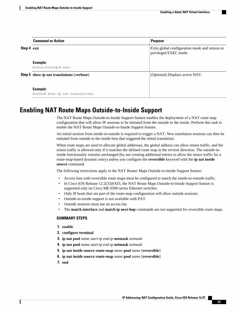
Command or Action Purpose
Step 4 exit
Example:Router(config)# exit
Exits global configuration mode and returns toprivileged EXEC mode.
Step 5 show ip nat translations [verbose]
Example:Router# show ip nat translations
(Optional) Displays active NAT.
Enabling NAT Route Maps Outside-to-Inside SupportThe NAT Route Maps Outside-to-Inside Support feature enables the deployment of a NAT route mapconfiguration that will allow IP sessions to be initiated from the outside to the inside. Perform this task toenable the NAT Route Maps Outside-to-Inside Support feature.
An initial session from inside-to-outside is required to trigger a NAT. New translation sessions can then beinitiated from outside to the inside host that triggered the initial translation.
When route maps are used to allocate global addresses, the global address can allow return traffic, and thereturn traffic is allowed only if it matches the defined route map in the reverse direction. The outside-to-inside functionality remains unchanged (by not creating additional entries to allow the return traffic for aroute-map-based dynamic entry) unless you configure the reversible keyword with the ip nat insidesource command.
The following restrictions apply to the NAT Router Maps Outside-to-Inside Support feature:
• Access lists with reversible route maps must be configured to match the inside-to-outside traffic.• In Cisco IOS Release 12.2(33)SXI5, the NAT Route Maps Outside-to-Inside Support feature is
supported only on Cisco ME 6500 series Ethernet switches.• Only IP hosts that are part of the route-map configuration will allow outside sessions.• Outside-to-inside support is not available with PAT.• Outside sessions must use an access list.• The match interface and match ip next-hop commands are not supported for reversible route maps.
SUMMARY STEPS
1. enable
2. configure terminal
3. ip nat pool name start-ip end-ip netmask netmask
4. ip nat pool name start-ip end-ip netmask netmask
5. ip nat inside source route-map name pool name [reversible]
6. ip nat inside source route-map name pool name [reversible]
7. end
Enabling NAT Route Maps Outside-to-Inside SupportEnabling a Static NAT Virtual Interface
IP Addressing: NAT Configuration Guide, Cisco IOS Release 12.4T 33

DETAILED STEPS
Command or Action Purpose
Step 1 enable
Example:Router> enable
Enables privileged EXEC mode.
• Enter your password if prompted.
Step 2 configure terminal
Example:Router(config)# configure terminal
Enters global configuration mode.
Step 3 ip nat pool name start-ip end-ip netmask netmask
Example:Router(config)# ip nat pool POOL-A 192.168.201.4 192.168.201.6 netmask 255.255.255.128
Defines a pool of network addresses for NAT.
Step 4 ip nat pool name start-ip end-ip netmask netmask
Example:Router(config)# ip nat pool POOL-B 192.168.201.7 192.168.201.9 netmask 255.255.255.128
Defines a pool of network addresses for NAT.
Step 5 ip nat inside source route-map name pool name [reversible]
Example:Router(config)# ip nat inside source route-map MAP-A pool POOL-A reversible
Enables outside-to-inside initiated sessions to useroute maps for destination-based NAT.
Step 6 ip nat inside source route-map name pool name [reversible]
Example:Router(config)# ip nat inside source route-map MAP-B pool POOL-B reversible
Enables outside-to-inside initiated sessions to useroute maps for destination-based NAT.
Step 7 end
Example:Router(config)# end
(Optional) Exits global configuration mode andreturns to privileged EXEC mode.
Configuring NAT of External IP Addresses OnlyWhen you configure NAT of external IP addresses, NAT can be configured to ignore all embedded IPaddresses for any application and traffic type. Traffic between a host and the traffic outside an enterprise’s
Configuring NAT of External IP Addresses Only Enabling a Static NAT Virtual Interface
IP Addressing: NAT Configuration Guide, Cisco IOS Release 12.4T34

network flows through the internal network. A router configured for NAT translates the packet to anaddress that can be routed inside the internal network. If the intended destination is outside an enterprise’snetwork, the packet gets translated back to an external address and is sent out.
Note When you configure the ip nat outside source static command to add static routes for outside localaddresses, there is a delay in the translation of packets and packets are dropped. The packets are droppedbecause a shortcut is not created for the initial synchronize (SYN) packet when NAT is configured forstatic translation. To avoid dropped packets, configure either the ip nat outside source static add-routecommand or the ip route command.
Benefits of Configuring NAT of External IP Addresses Only are:
• Supports public and private network architecture with no specific route updates.• Gives the end client a usable IP address at the starting point. This address is the address used for IPsec
connections and traffic.• Allows the use of network architecture that requires only the header translation.• Allows an enterprise to use the Internet as its enterprise backbone network.
SUMMARY STEPS
1. enable
2. configure terminal
3. ip nat inside source {list {access-list-number | access-list-name} pool pool-name [overload] | staticnetwork local-ip global-ip [no-payload]}
4. ip nat inside source {list {access-list-number | access-list-name} pool pool-name [overload] | static{tcp | udp} local-ip local-port global-ip global-port [no-payload]}
5. ip nat inside source {list {access-list-number | access-list-name} pool pool-name [overload] | static[network] local-network-mask global-network-mask [no-payload]}
6. ip nat outside source {list {access-list-number | access-list-name} pool pool-name [overload] | staticlocal-ip global-ip [no-payload]}
7. ip nat outside source {list {access-list-number | access-list-name} pool pool-name [overload] | static{tcp | udp} local-ip local-port global-ip global-port [no-payload]}
8. ip nat outside source {list {access-list-number | access-list-name} pool pool-name [overload] | static[network] local-network-mask global-network-mask [no-payload]}
9. exit
10. show ip nat translations [verbose]
DETAILED STEPS
Command or Action Purpose
Step 1 enable
Example:Router> enable
Enables privileged EXEC mode.
• Enter your password ifprompted.
Configuring NAT for IP Address ConservationEnabling a Static NAT Virtual Interface
IP Addressing: NAT Configuration Guide, Cisco IOS Release 12.4T 35

Command or Action Purpose
Step 2 configure terminal
Example:Router# configure terminal
Enters global configuration mode.
Step 3 ip nat inside source {list {access-list-number | access-list-name} pool pool-name[overload] | static network local-ip global-ip [no-payload]}
Example:Router(config)# ip nat inside source static network 10.1.1.1 192.168.251.0/24 no-payload
Disables the network packettranslation on the inside hostrouter.
Step 4 ip nat inside source {list {access-list-number | access-list-name} pool pool-name[overload] | static {tcp | udp} local-ip local-port global-ip global-port [no-payload]}
Example:Router(config)# ip nat inside source static tcp 10.1.1.1 2000 192.168.1.1 2000 no-payload
Disables port packet translation onthe inside host router.
Step 5 ip nat inside source {list {access-list-number | access-list-name} pool pool-name[overload] | static [network] local-network-mask global-network-mask [no-payload]}
Example:Router(config)# ip nat inside source static 10.1.1.1 192.168.1.1 no-payload
Disables packet translation on theinside host router.
Step 6 ip nat outside source {list {access-list-number | access-list-name} pool pool-name[overload] | static local-ip global-ip [no-payload]}
Example:Router(config)# ip nat outside source static 10.1.1.1 192.168.1.1 no-payload
Disables packet translation on theoutside host router.
Step 7 ip nat outside source {list {access-list-number | access-list-name} pool pool-name[overload] | static {tcp | udp} local-ip local-port global-ip global-port [no-payload]}
Example:Router(config)# ip nat outside source static tcp 10.1.1.1 20000 192.168.1.1 20000 no-payload
Disables port packet translation onthe outside host router.
Configuring NAT for IP Address Conservation Enabling a Static NAT Virtual Interface
IP Addressing: NAT Configuration Guide, Cisco IOS Release 12.4T36

Command or Action Purpose
Step 8 ip nat outside source {list {access-list-number | access-list-name} pool pool-name[overload] | static [network] local-network-mask global-network-mask [no-payload]}
Example:Router(config)# ip nat outside source static network 10.1.1.1 192.168.251.0/24 no-payload
Disables network packettranslation on the outside hostrouter.
Step 9 exit
Example:Router(config)# exit
Exits global configuration modeand returns to privileged EXECmode.
Step 10 show ip nat translations [verbose]
Example:Router# show ip nat translations
Displays active NAT.
Configuring the NAT Inside Server FeatureThe NAT Default Inside Server feature helps forward packets from the outside to a specified inside localaddress. Traffic that does not match any existing dynamic translations or static port translations isredirected, and the packets are not dropped.
Dynamic mapping and interface overload can be configured for gaming devices. For online games, outsidetraffic comes on a different UDP port. If a packet is destined for the 806 interface from outside anenterprise’s network and there no match in the NAT table for the fully extended entry or the static portentry, the packet is forwarded to the gaming device using a simple static entry.
Note• You can use the feature to configure gaming devices with an IP address that is different from that of
the PC. To avoid unwanted traffic or DoS attacks, use access lists.• For traffic going from the PC to the outside, it is better to use a route map so that extended entries are
created.
SUMMARY STEPS
1. enable
2. configure terminal
3. ip nat inside source static local-ip interface type number
4. ip nat inside source static tcp local-ip local-port interface global-port
5. exit
6. show ip nat translations [verbose]
Configuring the NAT Inside Server FeatureEnabling a Static NAT Virtual Interface
IP Addressing: NAT Configuration Guide, Cisco IOS Release 12.4T 37

DETAILED STEPS
Command or Action Purpose
Step 1 enable
Example:Router> enable
Enables privileged EXEC mode.
• Enter your password if prompted.
Step 2 configure terminal
Example:Router# configure terminal
Enters global configuration mode.
Step 3 ip nat inside source static local-ip interface type number
Example:Router(config)# ip nat inside source static 10.1.1.1 interface Ethernet 1/1
Enables static NAT on the interface.
Step 4 ip nat inside source static tcp local-ip local-port interface global-port
Example:Router(config)# ip nat inside source static tcp 10.1.1.1 23 interface 23
(Optional) Enables the use of telnet to the routerfrom the outside.
Step 5 exit
Example:Router(config)# exit
Exits global configuration mode and returns toprivileged EXEC mode.
Step 6 show ip nat translations [verbose]
Example:Router# show ip nat translations
(Optional) Displays active NAT.
Configuring Support for Users with Static IP AddressesConfiguring support for users with static IP addresses enables those users to establish an IP session in apublic wireless LAN environment.
The NAT Static IP Support feature extends the capabilities of public wireless LAN providers to supportusers configured with a static IP address. By configuring a router to support users with a static IP address,public wireless LAN providers extend their services to a greater number of potential users, which can leadto greater user satisfaction and additional revenue.
Users with static IP addresses can use services of the public wireless LAN provider without changing theirIP address. NAT entries are created for static IP clients and a routable address is provided.
Configuring Support for Users with Static IP Addresses Enabling a Static NAT Virtual Interface
IP Addressing: NAT Configuration Guide, Cisco IOS Release 12.4T38

Before configuring support for users with static IP addresses, you must first enable NAT on your router andconfigure a RADIUS server host.
SUMMARY STEPS
1. enable
2. configure terminal
3. interface type number
4. ip nat inside
5. exit
6. ip nat allow-static-host
7. ip nat pool name start-ip end-ip netmask netmask accounting list-name
8. ip nat inside source list access-list-number pool name
9. access-list access-list-number deny ip source
10. end
11. show ip nat translations verbose
DETAILED STEPS
Command or Action Purpose
Step 1 enable
Example:Router> enable
Enables privileged EXEC mode.
• Enter your password if prompted.
Step 2 configure terminal
Example:Router# configure terminal
Enters global configuration mode.
Step 3 interface type number
Example:Router(config)# interface ethernet 1
Configures an interface and enters interface configurationmode.
Step 4 ip nat inside
Example:Router(config-if)# ip nat inside
Marks the interface as connected to the inside.
Step 5 exit
Example:Router(config-if)# exit
Exits interface configuration mode and returns to globalconfiguration mode.
Configuring NAT for IP Address ConservationEnabling a Static NAT Virtual Interface
IP Addressing: NAT Configuration Guide, Cisco IOS Release 12.4T 39

Command or Action Purpose
Step 6 ip nat allow-static-host
Example:Router(config)# ip nat allow-static-host
Enables static IP address support.
• Dynamic Address Resolution Protocol (ARP) learningwill be disabled on this interface, and NAT will controlthe creation and deletion of ARP entries for the static IPhost.
Step 7 ip nat pool name start-ip end-ip netmask netmaskaccounting list-name
Example:Router(config)# ip nat pool pool1 172.16.0.0 172.16.0.254 netmask 255.255.255.0 accounting WLAN-ACCT
Specifies an existing RADIUS profile name to be used forauthentication of the static IP host.
Step 8 ip nat inside source list access-list-number pool name
Example:Router(config)# ip nat inside source list 1 pool net-208
Specifies the access list and pool to be used for static IPsupport.
• The specified access list must permit all traffic.
Step 9 access-list access-list-number deny ip source
Example:Router(config)# access-list 1 deny ip 192.168.196.51
Removes the router’s own traffic from NAT.
• The source argument is the IP address of the router thatsupports the NAT Static IP Support feature.
Step 10 end
Example:Router(config)# end
(Optional) Exits global configuration mode and returns toprivileged EXEC mode.
Step 11 show ip nat translations verbose
Example:Router# show ip nat translations verbose
(Optional) Displays active NAT translations and additionalinformation for each translation table entry, including howlong ago the entry was created and used.
Examples
The following is sample output from the show ip nat translations verbose command:
Router# show ip nat translations verbose
--- 172.16.0.0 10.1.1.1 --- ---create 00:05:59, use 00:03:39, left 23:56:20, Map-Id(In): 1, flags: none wlan-flags: Secure ARP added, Accounting Start sent Mac-Address:0010.7bc2.9ff6 Input-IDB:Ethernet1/2, use_count: 0, entry-id:7, lc_entries: 0
Configuring NAT for IP Address Conservation Enabling a Static NAT Virtual Interface
IP Addressing: NAT Configuration Guide, Cisco IOS Release 12.4T40

Configuring Support for ARP PingWhen the static IP client’s NAT entry times out, the NAT entry and the secure ARP entry associations aredeleted for the client. Reauthentication with the Service Selection Gateway (SSG) is needed for the client toreestablish WLAN services. The ARP Ping feature enables the NAT entry and the secure ARP entry to notbe deleted when the static IP client exists in the network where the IP address is unchanged afterauthentication.
An ARP ping is necessary to determine static IP client existence and to restart the NAT entry timer.
SUMMARY STEPS
1. enable
2. configure terminal
3. ip nat pool name start-ip end-ip prefix-length prefix-length [accounting method-list-name] [arp-ping]
4. ip nat translation arp -ping-timeout [seconds]
5. end
DETAILED STEPS
Command or Action Purpose
Step 1 enable
Example:Router> enable
Enables privileged EXEC mode.
• Enter your password if prompted.
Step 2 configure terminal
Example:Router# configure terminal
Enters global configuration mode.
Step 3 ip nat pool name start-ip end-ip prefix-length prefix-length[accounting method-list-name] [arp-ping]
Example:Router(config)# ip nat pool net-208 172.16.233.208 172.16.233.223 prefix-length 28 accounting radius1 arp-ping
Defines a pool of IP addresses for NAT.
Step 4 ip nat translation arp -ping-timeout [seconds]
Example:Router(config)# ip nat translation arp-ping-timeout 600
Changes the amount of time after each networkaddress translation.
Configuring Support for ARP PingEnabling a Static NAT Virtual Interface
IP Addressing: NAT Configuration Guide, Cisco IOS Release 12.4T 41
Command or Action Purpose
Step 5 end
Example:Router(config)# end
(Optional) Exits global configuration mode andreturns to privileged EXEC mode.
Configuring the Rate Limiting NAT Translation FeatureLimiting the number of concurrent NAT operations using the Rate Limiting NAT Translation featureprovides users more control over how NAT addresses are used. The Rate Limiting NAT Translation featurecan be used to limit the effects of viruses, worms, and DoS attacks.
Because NAT is a CPU-intensive process, router performance can be adversely affected by DoS attacks,viruses, and worms that target NAT. The Rate Limiting NAT Translation feature allows you to limit themaximum number of concurrent NAT requests on a router.
Prerequisites for configuring the Rate Limiting NAT Translation feature are as follows:
• Classify current NAT usage and determine the sources of requests for NAT. A specific host, accesscontrol list, or VRF instance generating an unexpectedly high number of NAT requests may be thesource of a malicious virus or worm attack.
• Once you have identified the source of excess NAT requests, you can set a NAT rate limit thatcontains a specific host, access control list, or VRF instance, or you can set a general limit for themaximum number of NAT requests allowed regardless of their source.
SUMMARY STEPS
1. enable
2. show ip nat translations
3. configure terminal
4. ip nat translation max-entries {number | all-vrf number | host ip-address number | list listnamenumber | vrf name number}
5. end
6. show ip nat statistics
DETAILED STEPS
Command or Action Purpose
Step 1 enable
Example:Router enable
Enables privileged EXEC mode.
• Enter your password if prompted.
Configuring the Rate Limiting NAT Translation Feature Enabling a Static NAT Virtual Interface
IP Addressing: NAT Configuration Guide, Cisco IOS Release 12.4T42

Command or Action Purpose
Step 2 show ip nat translations
Example:Router# show ip nat translations
(Optional) Displays active NAT.
• A specific host, access control list, or VRF instance generating anunexpectedly high number of NAT requests may be the source of amalicious virus or worm attack.
Step 3 configure terminal
Example:Router# configure terminal
Enters global configuration mode.
Step 4 ip nat translation max-entries {number |all-vrf number | host ip-address number |list listname number | vrf name number}
Example:Router(config)# ip nat translation max-entries 300
Configures the maximum number of NAT entries allowed from the specifiedsource.
• The maximum number of allowed NAT entries is 2147483647, althougha typical range for a NAT rate limit is 100 to 300 entries.
• When you configure a NAT rate limit for all VRF instances, each VRFinstance is limited to the maximum number of NAT entries that youspecify.
• When you configure a NAT rate limit for a specific VRF instance, youcan specify a maximum number of NAT entries for the named VRFinstance that is greater than or less than that allowed for all VRFinstances.
Step 5 end
Example:Router(config)# end
Exits global configuration mode and returns to privileged EXEC mode.
Step 6 show ip nat statistics
Example:Router# show ip nat statistics
(Optional) Displays current NAT usage information, including NAT ratelimit settings.
• After setting a NAT rate limit, use the show ip nat statistics commandto verify the current NAT rate limit settings.
Configuration Examples for Configuring NAT for IP AddressConservation
• Example: Configuring Static Translation of Inside Source Addresses, page 44• Example: Configuring Dynamic Translation of Inside Source Addresses, page 44• Example: Allowing Internal Users Access to the Internet, page 45• Example: Allowing Overlapping Networks to Communicate Using NAT, page 45• Example: Configuring the NAT Virtual Interface, page 46• Example: Configuring Server TCP Load Balancing, page 46
Configuring NAT for IP Address ConservationConfiguration Examples for Configuring NAT for IP Address Conservation
IP Addressing: NAT Configuration Guide, Cisco IOS Release 12.4T 43

• Example: Enabling Route Maps on Inside Interfaces, page 46
• Example: Enabling NAT Route Maps Outside-to-Inside Support, page 46
• Example: Configuring NAT Translation of External IP Addresses Only, page 47
• Example: Configuring Support for Users with Static IP Addresses, page 47
• Example: Configuring the Rate Limiting NAT Translation Feature , page 47
Example: Configuring Static Translation of Inside Source AddressesThe following example translates between inside hosts addressed from the 10.114.11.0 network to theglobally unique 172.31.233.208/28 network. Further packets from outside hosts addressed from the10.114.11.0 network (the true 10.114.11.0 network) are translated to appear to be from the 10.0.1.0/24network.
ip nat pool net-208 172.31.233.208 172.31.233.223 prefix-length 28ip nat pool net-10 10.0.1.0 10.0.1.255 prefix-length 24ip nat inside source list 1 pool net-208ip nat outside source list 1 pool net-10!interface ethernet 0 ip address 172.31.232.182 255.255.255.240 ip nat outside!interface ethernet 1 ip address 10.114.11.39 255.255.255.0 ip nat inside!access-list 1 permit 10.114.11.0 0.0.0.255
The following example shows NAT configured on the provider edge (PE) router with a static route to theshared service for the vrf1 and vrf2 VPNs. NAT is configured as inside source static one-to-one translation.
ip nat pool outside 10.4.4.1 10.4.4.254 netmask 255.255.255.0ip nat outside source list 1 pool mypoolaccess-list 1 permit 172.16.18.0 0.0.0.255ip nat inside source static 192.168.121.33 10.2.2.1 vrf vrf1ip nat inside source static 192.169.121.33.10.2.2.2 vrf vrf2
Example: Configuring Dynamic Translation of Inside Source AddressesThe following example translates between inside hosts addressed from either the 192.168.1.0 or the192.168.2.0 network to the globally unique 172.31.233.208/28 network:
ip nat pool net-208 172.31.233.208 172.31.233.223 prefix-length 9ip nat inside source list 1 pool net-208!interface ethernet 0 ip address 172.31.232.182 255.255.255.240 ip nat outside!interface ethernet 1 ip address 192.168.1.94 255.255.255.0 ip nat inside!access-list 1 permit 192.168.1.0 0.0.0.255access-list 1 permit 192.168.2.0 0.0.0.255
The following example translates only traffic local to the provider edge device running NAT (NAT-PE):
ip nat inside source list 1 interface e 0 vrf vrf1 overloadip nat inside source list 1 interface e 0 vrf vrf2 overload!
Example: Configuring Static Translation of Inside Source Addresses Configuration Examples for Configuring NAT for IP Address Conservation
IP Addressing: NAT Configuration Guide, Cisco IOS Release 12.4T44

ip route vrf vrf1 0.0.0.0 0.0.0.0 192.168.1.1ip route vrf vrf2 0.0.0.0 0.0.0.0 192.168.1.1!access-list 1 permit 10.1.1.1.0 0.0.0.255!ip nat inside source list 1 interface e 1 vrf vrf1 overloadip nat inside source list 1 interface e 1 vrf vrf2 overload!ip route vrf vrf1 0.0.0.0 0.0.0.0 172.16.1.1 globalip route vrf vrf2 0.0.0.0 0.0.0.0 172.16.1.1 globalaccess-list 1 permit 10.1.1.0 0.0.0.255
Example: Allowing Internal Users Access to the InternetThe following example creates a pool of addresses named net-208. The pool contains addresses from172.31.233.208 to 172.31.233.233. Access list 1 allows packets having the SA from 192.168.1.0 to192.168.1.255. If no translation exists, packets matching access list 1 are translated to an address from thepool. The router allows multiple local addresses (192.168.1.0 to 192.168.1.255) to use the same globaladdress. The router retains port numbers to differentiate the connections.
ip nat pool net-208 172.31.233.208 172.31.233.233 netmask 255.255.255.240access-list 1 permit 192.168.1.0 0.0.0.255ip nat inside source list 1 pool net-208 overloadinterface ethernet 1 ip address 172.31.232.182 255.255.255.240 ip nat inside!interface ethernet 0 ip address 192.168.1.94 255.255.255.0 ip nat outside!
Example: Allowing Overlapping Networks to Communicate Using NAT
Example: Configuring Static Translation of Overlapping Networks
ip nat inside source static 192.168.121.33 10.2.2.1!interface ethernet 1 ip address 10.114.11.39 255.255.255.0 ip nat inside!interface ethernet 0 ip address 172.16.232.182 255.255.255.240 ip nat outside
Example: Configuring Dynamic Translation of Overlapping Networks
In the following example, the addresses in the local network are being used legitimately by someone elseon the Internet. An extra translation is required to access the external network. Pool, net-10 is a pool ofoutside local IP addresses. The ip nat outside source list 1 pool net-10 command translates the addressesof hosts from the outside overlapping network to addresses in that pool.
ip nat pool net-208 172.31.233.208 172.31.233.223 prefix-length 28ip nat pool net-10 10.0.1.0 10.0.1.255 prefix-length 24access-list 1 permit 10.114.11.0 0.0.0.255ip nat inside source list 1 pool net-208ip nat outside source list 1 pool net-10!interface ethernet 1 ip address 10.114.11.39 255.255.255.0 ip nat inside!
Example: Allowing Internal Users Access to the InternetConfiguration Examples for Configuring NAT for IP Address Conservation
IP Addressing: NAT Configuration Guide, Cisco IOS Release 12.4T 45
interface ethernet 0 ip address 172.16.232.182 255.255.255.240 ip nat outside
Example: Configuring the NAT Virtual Interface
Example: Enabling a Dynamic NAT Virtual Interface
interface FastEthernet 1 ip nat enable!ip nat pool pool1 192.168.200.225 192.168.200.254 netmask 255.255.255.0 add-routeip nat source list 1 pool pool1 vrf vrf1ip nat source list 1 pool 1 vrf vrf2 overload!
Example: Enabling a Static NAT Virtual Interface
interface FastEthernet 1 ip nat enable!ip nat source static 192.168.123.1 182.168.125.10 vrf vr1!
Example: Configuring Server TCP Load BalancingIn the following example, the goal is to define a virtual address, connections to which are distributedamong a set of real hosts. The pool defines addresses of real hosts. The access list defines the virtualaddress. If a translation does not already exist, TCP packets from serial interface 0 (the outside interface),whose destination matches the access list, are translated to an address from the pool.
ip nat pool real-hosts 192.168.15.2 192.168.15.15 prefix-length 28 type rotaryaccess-list 2 permit 192.168.15.1ip nat inside destination list 2 pool real-hostsinterface ethernet 0 ip address 192.168.15.129 255.255.255.240 ip nat inside!interface serial 0 ip address 192.168.15.17 255.255.255.240 ip nat outside!
Example: Enabling Route Maps on Inside Interfacesip nat inside source static 192.168.201.6 192.168.201.21!
Example: Enabling NAT Route Maps Outside-to-Inside SupportThe following example shows how to configure route map A and route map B to allow outside-to-insidetranslation for a destination-based NAT:
ip nat pool POOL-A 192.168.201.4 192.168.201.6 netmask 255.255.255.128ip nat pool POOL-B 192.168.201.7 192.168.201.9 netmask 255.255.255.128ip nat inside source route-map MAP-A pool POOL-A reversibleip nat inside source route-map MAP-B pool POOL-B reversible
Example: Configuring the NAT Virtual Interface Configuration Examples for Configuring NAT for IP Address Conservation
IP Addressing: NAT Configuration Guide, Cisco IOS Release 12.4T46
Example: Configuring NAT Translation of External IP Addresses Onlyip nat inside source static network 10.1.1.1 192.168.2510/24 no-payloadip nat inside source static tcp 10.1.1.1 2000 192.168.1.1 2000 no-payloadip nat inside source static 10.1.1.1 192.168.1.1 no-payloadip nat outside source static 10.1.1. 192.168.1.1 no-payloadip nat outside source static tcp 10.1.1.1 20000 192.168.1.1 20000 no-payloadip nat outside source static network 10.1.1.1 192.168.251.0/24 no-payload
Example: Configuring Support for Users with Static IP Addressesinterface ethernet 1 ip nat inside!ip nat allow-static-hostip nat pool pool1 172.16.0.0 172.16.0.254 netmask 255.255.255.0 accounting WLAN-ACCTip nat inside source list 1 pool net-208access-list 1 deny ip 192.168.196.51
Example: Configuring the Rate Limiting NAT Translation FeatureThe following example shows how to limit the maximum number of allowed NAT entries to 300:
ip nat translation max-entries 300
The following example shows how to limit the VRF instance named “vrf1” to 150 NAT entries:
ip nat translation max-entries vrf vrf1 150
The following example shows how to limit each VRF instance to 200 NAT entries:
ip nat translation max-entries all-vrf 200
The following example shows how to limit the VRF instance named “vrf2” to 225 NAT entries, but limitall other VRF instances to 100 NAT entries each:
ip nat translation max-entries all-vrf 100ip nat translation max-entries vrf vrf2 225
The following example shows how to limit the access control list named “vrf3” to 100 NAT entries:
ip nat translation max-entries list vrf3 100
The following example shows how to limit the host at IP address 10.0.0.1 to 300 NAT entries:
ip nat translation max-entries host 10.0.0.1 300
Where to Go Next• To configure NAT for use with application-level gateways, see the “Using Application Level
Gateways with NAT” module.• To verify, monitor, and maintain NAT, see the “Monitoring and Maintaining NAT” module.• To integrate NAT with Multiprotocol Label Switching (MPLS) VPNs, see the “Integrating NAT with
MPLS VPNs” module.• To configure NAT for high availability, see the “Configuring NAT for High Availability” module.
Example: Configuring NAT Translation of External IP Addresses OnlyWhere to Go Next
IP Addressing: NAT Configuration Guide, Cisco IOS Release 12.4T 47
Additional ReferencesRelated Documents
Related Topic Document Title
Cisco IOS commands Cisco IOS Master Commands List, All Releases
NAT commands: complete command syntax,command mode command history, defaults, usageguidelines, and examples
Cisco IOS IP Addressing Services CommandReference
Application Level Gateways “Using Application Level Gateways with NAT”module
IP Access List Sequence Numbering IP Access List Sequence Numbering document
NAT on a Stick technology note Network Address Translation on a Stick technologynote
NAT maintenance “Monitoring and Maintaining NAT” module
RADIUS attributes overview “RADIUS Attributes Overview and RADIUS IETFAttributes” module
Using Hot Standby Router Protocol (HSRP) andStateful NAT (SNAT) for high availability
“Configuring NAT for High Availability” module
Using NAT with MPLS VPNs “Integrating NAT with MPLS VPNs” module
Standards and RFCs
Standard/RFC Title
RFC 1597 Internet Assigned Numbers Authority
RFC 1631 The IP Network Address Translation (NAT)
RFC 1918 Address Allocation for Private Internets
RFC 2663 IP Network Address Translation (NAT)Terminology and Considerations
RFC 3022 Traditional IP Network Address Translation(Traditional NAT)
Configuring NAT for IP Address Conservation Additional References
IP Addressing: NAT Configuration Guide, Cisco IOS Release 12.4T48

MIBs
MIBs MIBs Link
None To locate and download MIBs for selectedplatforms, Cisco IOS releases, and feature sets, useCisco MIB Locator found at the following URL:
http://www.cisco.com/go/mibs
Technical Assistance
Description Link
The Cisco Support and Documentation websiteprovides online resources to downloaddocumentation, software, and tools. Use theseresources to install and configure the software andto troubleshoot and resolve technical issues withCisco products and technologies. Access to mosttools on the Cisco Support and Documentationwebsite requires a Cisco.com user ID andpassword.
http://www.cisco.com/cisco/web/support/index.html
Feature Information for Configuring NAT for IP AddressConservation
The following table provides release information about the feature or features described in this module.This table lists only the software release that introduced support for a given feature in a given softwarerelease train. Unless noted otherwise, subsequent releases of that software release train also support thatfeature.
Use Cisco Feature Navigator to find information about platform support and Cisco software image support.To access Cisco Feature Navigator, go to www.cisco.com/go/cfn. An account on Cisco.com is not required.
Configuring NAT for IP Address ConservationFeature Information for Configuring NAT for IP Address Conservation
IP Addressing: NAT Configuration Guide, Cisco IOS Release 12.4T 49

Table 1 Feature Information for Configuring NAT for IP Address Conservation
Feature Name Releases Feature Information
NAT Ability to Use Route Mapswith Static Translation
12.2.(4)T The NAT Ability to Use Route Mapswith Static Translation featureprovides a dynamic translationcommand that can specify a route mapto be processed instead of an accesslist. A route map allows you to matchany combination of the access list,next-hop IP address, and outputinterface to determine which pool touse. The ability to use route maps withstatic translations enables NATmultihoming capability with staticaddress translations.
NAT Translation of External IPAddresses Only
12.2(4)T
12.2(4)T2
15.0(1)S
You can use the NAT Translation ofExternal IP Addresses Only feature,NAT can be configured to ignore allembedded IP addresses for anyapplication and traffic type.
Rate Limiting NAT Translation 12.3(4)T
15.0(1)S
The Rate Limiting NAT Translationfeature provides the ability to limit themaximum number of concurrentNetwork Address Translation (NAT)operations on a router. In addition togiving users more control over howNAT addresses are used, the RateLimiting NAT Translation feature canbe used to limit the effects of viruses,worms, and denial-of-service attacks.
NAT RTSP Support UsingNBAR
12.3(7)T The NAT Real Time StreamingProtocol (RTSP) Support Using NBARfeature is a client/server multimediapresentation control protocol thatsupports multimedia applicationdelivery. Applications that use RTSPinclude Windows Media Services(WMS) by Microsoft, QuickTime byApple Computer, and RealSystem G2by RealNetworks.
NAT Static IP Support 12.3(7)T The NAT Static IP Support featureprovides support for users with staticIP addresses, enabling those users toestablish an IP session in a publicwireless LAN environment.
Configuring NAT for IP Address Conservation Feature Information for Configuring NAT for IP Address Conservation
IP Addressing: NAT Configuration Guide, Cisco IOS Release 12.4T50

Feature Name Releases Feature Information
NAT Route Maps Outside-to-Inside Support
12.2(33)SXI5
12.3(14)T
The NAT Route Maps Outside-to-Inside Support feature enables thedeployment of a NAT route mapconfiguration that allows IP sessions tobe initiated from the outside to theinside.
NAT Default Inside Server 12.3(13)T The NAT Default Inside Server featureenables forwarding of packets fromoutside to a specified inside localaddress.
NAT Virtual Interface 12.3(14)T The NAT Virtual Interface featureremoves the requirement to configurean interface as either Network AddressTranslation (NAT) inside or NAToutside. An interface can be configuredto use or not use NAT.
Support for ARP Ping in a PublicWireless LAN
12.4(6)T The Support for ARP Ping in a PublicWireless LAN feature ensures that theNAT entry and the secure ARP entryfrom removal when the static IP clientexists in the network, where the IPaddress is unchanged afterauthentication.
NAT Static and Dynamic RouteMap Name-Sharing
15.0(1)M The NAT Static and Dynamic RouteMap Name-Sharing feature providesthe ability to configure static anddynamic NAT to share the same routemap name, while enforcing precedenceof static NAT over dynamic NAT.
Cisco and the Cisco logo are trademarks or registered trademarks of Cisco and/or its affiliates in the U.S.and other countries. To view a list of Cisco trademarks, go to this URL: www.cisco.com/go/trademarks.Third-party trademarks mentioned are the property of their respective owners. The use of the word partnerdoes not imply a partnership relationship between Cisco and any other company. (1110R)
Any Internet Protocol (IP) addresses and phone numbers used in this document are not intended to beactual addresses and phone numbers. Any examples, command display output, network topology diagrams,and other figures included in the document are shown for illustrative purposes only. Any use of actual IPaddresses or phone numbers in illustrative content is unintentional and coincidental.
Configuring NAT for IP Address Conservation
IP Addressing: NAT Configuration Guide, Cisco IOS Release 12.4T 51

Example: Configuring the Rate Limiting NAT Translation Feature
IP Addressing: NAT Configuration Guide, Cisco IOS Release 12.4T52

Using Application Level Gateways with NAT
This module describes the basic tasks to configure an Application Level Gateway (ALG) with NetworkAddress Translation (NAT). This module also provides information about the protocols that use ALG forIP header translation.
NAT performs translation service on any TCP/UDP traffic that does not carry the source and destinationIP addresses in the application data stream. These protocols include HTTP, TFTP, telnet, archie, finger,Network Time Protocol (NTP), Network File System (NFS), remote login (rlogin), remote shell (rsh)protocol, and remote copy (rcp). Specific protocols that do embed IP the address information within thepayload require support of an ALG.
NAT with an ALG will translate packets from applications that do not use H.323, as long as theapplications use port 1720.
The Support for IPsec ESP Through NAT feature provides the ability to support multiple concurrent IPsecEncapsulating Security Payload (ESP) tunnels or connections through a Cisco IOS NAT deviceconfigured in Overload or Port Address Translation (PAT) mode.
• Finding Feature Information, page 53• Prerequisites for Using Application Level Gateways with NAT, page 53• Restrictions for Using Application Level Gateways with NAT, page 54• Information About Using Application Level Gateways with NAT, page 54• How to Configure Application Level Gateways with NAT, page 58• Configuration Examples for Using Application Level Gateways with NAT, page 64• Where to Go Next, page 65• Additional References, page 65• Feature Information for Using Application Level Gateways with NAT, page 66
Finding Feature InformationYour software release may not support all the features documented in this module. For the latest featureinformation and caveats, see the release notes for your platform and software release. To find informationabout the features documented in this module, and to see a list of the releases in which each feature issupported, see the Feature Information Table at the end of this document.
Use Cisco Feature Navigator to find information about platform support and Cisco software image support.To access Cisco Feature Navigator, go to www.cisco.com/go/cfn. An account on Cisco.com is not required.
Prerequisites for Using Application Level Gateways with NAT
IP Addressing: NAT Configuration Guide, Cisco IOS Release 12.4T 53

• Before performing the tasks in this module, you should be familiar with the concepts described in the“Configuring NAT for IP Address Conservation” module.
• All access lists required for use with the tasks in this module should be configured prior to beginningthe configuration task. For information about how to configure an access list, see the “IP Access ListSequence Numbering” document.
• Before performing the tasks in this module, you should verify that the Session Initiation Protocol (SIP)and H.323 are not disabled. SIP and H.323 are enabled by default.
Restrictions for Using Application Level Gateways with NATNAT will translate only embedded IP version 4 addresses.
Information About Using Application Level Gateways withNAT
• Application Level Gateway, page 54
• IP Security, page 55
• Voice and Multimedia over IP Networks, page 55
• NAT Support of H.323 v2 RAS, page 56
• NAT Support for H.323 v3 and v4 in v2 Compatibility Mode, page 56
• NAT H.245 Tunneling Support, page 56
• NAT Support of Skinny Client Control Protocol, page 56
• NAT Support of SCCP Fragmentation, page 57
• NAT Segmentation with Layer 4 Forwarding, page 57
Application Level GatewayAn application level gateway is an application that translates IP address information inside the payload ofan applications packet.
Benefits of Configuring NAT ALG
• NAT support for SIP adds the ability to deploy Cisco IOS NAT between VoIP solutions based on SIP.• Customers can control their IP address scheme and include complete support for H.323 v2 gatekeeper
designs.• NAT enables customers to deploy private IP addresses within their network and perform translation to
public IP addresses when connecting to the Internet or interconnecting with another corporate network.• Normally ESP entries in the translation table are delayed from being transmitted until a reply is
received from the destination. With predictable security parameter indexes (SPIs) and SPI matching,the delay can be eliminated because the SPI entries are matched. Some third-party concentratorsrequire both the source and incoming ports to use port 500. Use of the preserve-port keyword withthe ip nat service command preserves the ports rather than changing one, which is required withregular NAT.
Application Level Gateway Restrictions for Using Application Level Gateways with NAT
IP Addressing: NAT Configuration Guide, Cisco IOS Release 12.4T54

IP SecurityIPsec is a set of extensions to the IP protocol family in a framework of open standards for ensuring secureprivate communications over the Internet. Based on standards developed by the IETF, IPsec ensuresconfidentiality, integrity, and authenticity of data communications across the public network and providescryptographic security services.
Secure tunnels between two peers, such as two routers, are provided and decisions are made as to whichpackets are considered sensitive and should be sent through these secure tunnels, and which parametersshould be used to protect these sensitive packets by specifying characteristics of these tunnels. When theIPsec peer receives a sensitive packet, it sets up the appropriate secure tunnel and sends the packet throughthe tunnel to the remote peer.
IPsec using ESP can pass through a router running NAT without any specific support from it as long asNetwork Address Port Translation (NAPT) or address overloading is not configured.
There are a number of factors to consider when attempting an IPsec VPN connection that traverses a NAPTdevice that represents multiple private internal IP addresses as a single public external IP address. Suchfactors include the capabilities of the VPN server and client, the capabilities of the NAPT device, andwhether more than one simultaneous connection is attempted across the NAPT device.
There are two possible methods for configuring IPsec on a router with NAPT:
• Encapsulate IPsec in a Layer 4 protocol such as TCP or UDP. In this case, IPsec is sneaking throughNAT. The NAT device is unaware of the encapsulation.
• Add IPsec specific support to NAPT. IPsec works with NAT in this case as opposed to sneakingthrough NAT. The NAT Support for IPsec ESP-- Phase II feature provides support for Internet KeyExchange (IKE) and ESP without encapsulation in tunnel mode through a Cisco IOS router configuredwith NAPT.
The recommended protocols to use when conducting IPsec sessions that traverse a NAPT device are TCPand UDP, but not all VPN servers or clients support TCP or UDP.
SPI Matching
Security Parameter Index ( SPI) matching is used to establish VPN connections between multiple pairs ofdestinations. NAT entries will immediately be placed in the translation table for endpoints matching theconfigured access list. SPI matching is available only for endpoints that choose SPIs according to thepredictive algorithm implemented in Cisco IOS Release 12.2(15)T.
Voice and Multimedia over IP NetworksSIP is a protocol developed by the IETF Multiparty Multimedia Session Control (MMUSIC) WorkingGroup. The Cisco SIP functionality equips Cisco routers to signal the setup of voice and multimedia callsover IP networks. SIP provides an alternative to H.323 within the VoIP internetworking software.
Session Description Protocol (SDP) is a protocol that describes multimedia sessions. SDP may be used inSIP message bodies to describe multimedia sessions used for creating and controlling multimedia sessionswith two or more participants.
The NAT Support for SIP feature allows SIP embedded messages passing through a router configured withNAT to be translated and encoded back to the packet. An ALG is used with NAT to translate the SIP orSDP messages.
IP SecurityInformation About Using Application Level Gateways with NAT
IP Addressing: NAT Configuration Guide, Cisco IOS Release 12.4T 55

Note By default support for SIP is enabled on port 5060. Therefore, NAT-enabled devices interpret all packetson this port as SIP call messages. If other applications in the system use port 5060 to send packets, theNAT service may corrupt the packet as it attempts to interpret the packet as a SIP call message.
NAT Support of H.323 v2 RASCisco IOS NAT supports all H.225 and H.245 message types, including those sent in the Registration,Admission, and Status (RAS) protocol. RAS provides a number of messages that are used by softwareclients and VoIP devices to register their location, request assistance in call setup, and control bandwidth.The RAS messages are directed toward an H.323 gatekeeper.
Some RAS messages include IP addressing information in the payload, typically meant to register a userwith the gatekeeper or learn about another user already registered. If these messages are not known toNAT, they cannot be translated to an IP address that will be visible to the public.
In Cisco IOS Release 12.2(2)T and later releases, embedded IP addresses can be inspected for potentialaddress translation. Prior to Cisco IOS Release 12.2(2)T, NAT did not support H.323 v2 RAS messages.
NAT Support for H.323 v3 and v4 in v2 Compatibility ModeH.323 is an ITU-T specification for transmitting audio, video, and data across a packet network. NATsupports four versions of the H.323 protocols: v1, v2, v3, and v4. The NAT Support for H.323 v3 and v4 inv2 Compatibility Mode feature enables Cisco NAT routers to support messages coded in H.323 v3 and v4when those messages contain fields compatible with H.323 v2. This feature does not add support for H.323capabilities introduced in v3 and v4, such as new message types or new fields that require addresstranslation.
NAT H.245 Tunneling SupportNAT H.245 tunneling allows H.245 tunneling in H.323 ALGs. NAT H.245 tunneling provides amechanism for supporting the H.245 tunnel message that is needed to create a media channel setup.
In order for an H.323 call to take place, an H.225 connection on TCP port 1720 needs to be opened. Whenthe H.225 connection is opened, the H.245 session is initiated and established. This connection can takeplace on a separate channel from the H.225 or it can be done using H.245 tunneling on the same H.225channel whereby the H.245 messages are embedded in the H.225 messages and sent on the previouslyestablished H.225 channel.
If the H.245 tunneled message is not understood, the media address or port will be left untranslated by theCisco IOS NAT, resulting in failure in media traffic. H.245 FastConnect procedures will not help becauseFastConnect is terminated as soon as an H.245 tunneled message is sent.
NAT Support of Skinny Client Control ProtocolCisco IP phones use the SCCP to connect with and register to Cisco CallManager.
To be able to configure Cisco IOS NAT between the IP phone and Cisco CallManager in a scalableenvironment, NAT needs to be able to detect the SCCP and understand the information passed within themessages. Messages flow back and forth that include IP address and port information used to identify otherIP phone users with which a call can be placed.
The SCCP client to Cisco CallManager communication typically flows from inside to outside. DomainName System (DNS) should be used to resolve the Cisco CallManager IP address connection when the
NAT Support of H.323 v2 RAS Information About Using Application Level Gateways with NAT
IP Addressing: NAT Configuration Guide, Cisco IOS Release 12.4T56

Cisco CallManager is on the inside (behind the NAT device), or static NAT should be configured to reachthe Cisco CallManager in the inside.
When an IP phone attempts to connect to the Cisco CallManager and it matches the configured NAT rules,NAT will translate the original source IP address and replace it with one from the configured pool. Thisnew address will be reflected in the Cisco CallManager and be visible to other IP phone users.
NAT Support of SCCP FragmentationSkinny control messages are exchanged over TCP. If either the IP phone or Cisco CallManager has beenconfigured to have a TCP maximum segment size (MSS) lower than the skinny control message payload,the skinny control message will be segmented across multiple TCP segments. Prior to this feature skinnycontrol message exchanges would fail in a TCP segmentation scenario because NAT skinny ALG was notable to reassemble the skinny control messages. The NAT SCCP Fragmentation Support feature addssupport for TCP segments for NAT skinny ALG. A fragmented payload that requires an IP or porttranslation will no longer be dropped.
Skinny control messages can also be IP fragmented but they are supported using Virtual FragmentationReassembly (VFR).
In Cisco IOS Release 15.1(3)T and later releases, NAT works with SCCP phones version 17 and higher.
NAT Segmentation with Layer 4 ForwardingThe NAT Segmentation with Layer 4 Forwarding feature is implemented for the H.323, SCCP, and TCPDNS protocols. NAT supports the processing of segmented H.323, SCCP, or TCP DNS messages that aresplit across multiple packets.
Layer 4 forwarding or TCP proxy is responsible for session handling that includes putting the sequencenumbers in order, acknowledging the numbers in a packet, resegmenting the translated packet if it is largerthan the MSS, and handling retransmissions in case of packet loss. Layer 4 forwarding also handles out-of-order packets. These packets are buffered and not dropped.
Layer 4 forwarding buffers the received packets and notifies NAT ALG when an in-order packet isavailable. It also sends acknowledgments to the end hosts for the received packets. Layer 4 forwarding alsosends the translated packets that it receives from NAT ALG back into the output packet path.
Restrictions
The NAT Segmentation with Layer 4 Forwarding feature does not work when:
• Cisco IOS firewalls are configured using the ip inspect name command. (Zone-based firewalls aresupported.)
• H.323, SCCP, or TCP DNS messages are larger than 18 KB.• Multiprotocol Label Switching (MPLS) is configured.• NAT and the Cisco CallManager are configured on the same device. In this case, the colocated
solution in Call Manager Express (CME) is used.• NAT Virtual Interface (NVI) is configured.• Stateful Network Address Translation (SNAT) is enabled.• The match-in-vrf keyword is configured along with the ip nat inside source command for packet
translation.• The packets are IPv6 packets.
NAT Support of SCCP FragmentationInformation About Using Application Level Gateways with NAT
IP Addressing: NAT Configuration Guide, Cisco IOS Release 12.4T 57
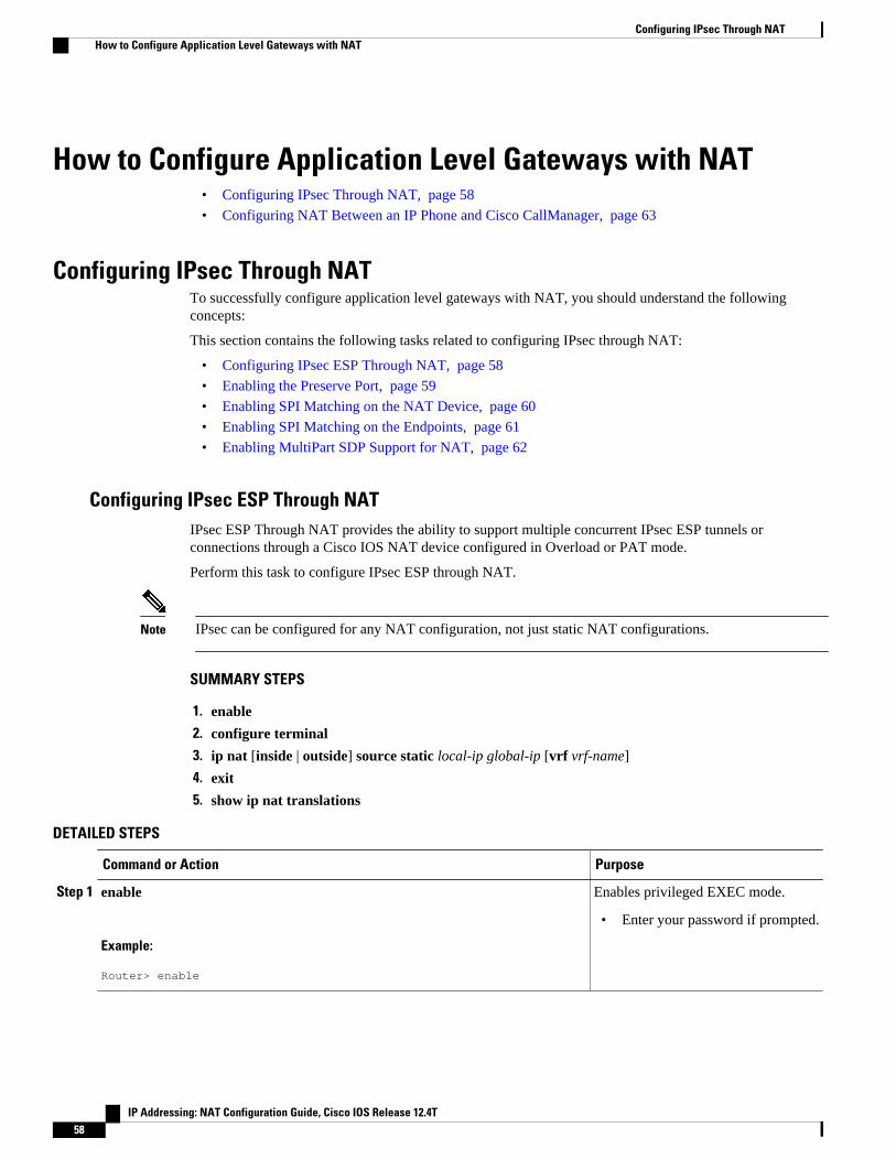
How to Configure Application Level Gateways with NAT• Configuring IPsec Through NAT, page 58
• Configuring NAT Between an IP Phone and Cisco CallManager, page 63
Configuring IPsec Through NATTo successfully configure application level gateways with NAT, you should understand the followingconcepts:
This section contains the following tasks related to configuring IPsec through NAT:
• Configuring IPsec ESP Through NAT, page 58
• Enabling the Preserve Port, page 59
• Enabling SPI Matching on the NAT Device, page 60
• Enabling SPI Matching on the Endpoints, page 61
• Enabling MultiPart SDP Support for NAT, page 62
Configuring IPsec ESP Through NATIPsec ESP Through NAT provides the ability to support multiple concurrent IPsec ESP tunnels orconnections through a Cisco IOS NAT device configured in Overload or PAT mode.
Perform this task to configure IPsec ESP through NAT.
Note IPsec can be configured for any NAT configuration, not just static NAT configurations.
SUMMARY STEPS
1. enable
2. configure terminal
3. ip nat [inside | outside] source static local-ip global-ip [vrf vrf-name]
4. exit
5. show ip nat translations
DETAILED STEPS
Command or Action Purpose
Step 1 enable
Example:
Router> enable
Enables privileged EXEC mode.
• Enter your password if prompted.
Configuring IPsec Through NAT How to Configure Application Level Gateways with NAT
IP Addressing: NAT Configuration Guide, Cisco IOS Release 12.4T58
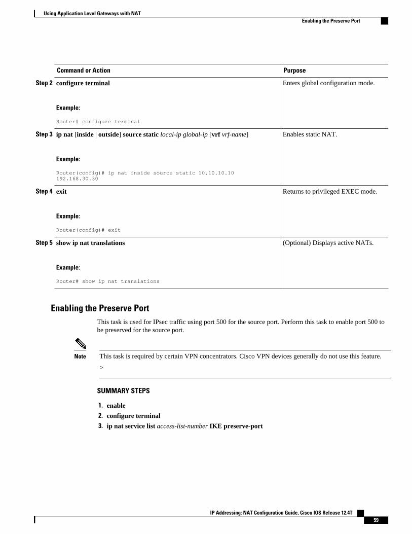
Command or Action Purpose
Step 2 configure terminal
Example:
Router# configure terminal
Enters global configuration mode.
Step 3 ip nat [inside | outside] source static local-ip global-ip [vrf vrf-name]
Example:
Router(config)# ip nat inside source static 10.10.10.10 192.168.30.30
Enables static NAT.
Step 4 exit
Example:
Router(config)# exit
Returns to privileged EXEC mode.
Step 5 show ip nat translations
Example:
Router# show ip nat translations
(Optional) Displays active NATs.
Enabling the Preserve PortThis task is used for IPsec traffic using port 500 for the source port. Perform this task to enable port 500 tobe preserved for the source port.
Note This task is required by certain VPN concentrators. Cisco VPN devices generally do not use this feature.
>
SUMMARY STEPS
1. enable
2. configure terminal
3. ip nat service list access-list-number IKE preserve-port
Using Application Level Gateways with NATEnabling the Preserve Port
IP Addressing: NAT Configuration Guide, Cisco IOS Release 12.4T 59

DETAILED STEPS
Command or Action Purpose
Step 1 enable
Example:
Router> enable
Enables privileged EXEC mode.
• Enter your password if prompted.
Step 2 configure terminal
Example:
Router# configure terminal
Enters global configuration mode.
Step 3 ip nat service list access-list-number IKE preserve-port
Example:
Router(config)# ip nat service list 10 IKE preserve-port
Specifies IPsec traffic that matches the access list topreserve the port.
Enabling SPI Matching on the NAT Device
Note SPI matching is disabled by default.
Security parameter index (SPI) matching is used to establish VPN connections between multiple pairs ofdestinations. NAT entries are immediately placed in the translation table for endpoints matching theconfigured access list. SPI matching is available only for endpoints that choose SPIs according to thepredictive algorithm implemented in Cisco IOS Release 12.2(15)T.
The generation of SPIs that are predictable and symmetric is enabled. SPI matching should be used inconjunction with NAT devices when multiple ESP connections across a NAT device are desired.
Cisco IOS software must be running on both the source router and the remote gateway enabling parallelprocessing.
Note SPI matching must be configured on the NAT device and both endpoint devices.
>
SUMMARY STEPS
1. enable
2. configure terminal
3. ip nat service list access-list-number ESP spi-match
Using Application Level Gateways with NAT Enabling SPI Matching on the NAT Device
IP Addressing: NAT Configuration Guide, Cisco IOS Release 12.4T60

DETAILED STEPS
Command or Action Purpose
Step 1 enable
Example:
Router> enable
Enables privileged EXEC mode.
• Enter your password if prompted.
Step 2 configure terminal
Example:
Router# configure terminal
Enters global configuration mode.
Step 3 ip nat service list access-list-number ESP spi-match
Example:
Router(config)# ip nat service list 10 ESP spi-match
Specifies an access list to enable SPI matching.
• This example shows how to enter ESP traffic matching list10 into the NAT table, making the assumption that bothdevices are Cisco devices and are configured to providematchable SPIs.
Enabling SPI Matching on the EndpointsCisco IOS XE software must be running on both the source router and the remote gateway enabling parallelprocessing.
Note SPI matching must be configured on the NAT device and both endpoint devices.
SUMMARY STEPS
1. enable
2. configure terminal
3. crypto ipsec nat-transparency spi-matching
4. end
DETAILED STEPS
Command or Action Purpose
Step 1 enable
Example:Router> enable
Enables privileged EXEC mode.
• Enter your password if prompted.
Using Application Level Gateways with NATEnabling SPI Matching on the Endpoints
IP Addressing: NAT Configuration Guide, Cisco IOS Release 12.4T 61

Command or Action Purpose
Step 2 configure terminal
Example:Router# configure terminal
Enters global configuration mode.
Step 3 crypto ipsec nat-transparency spi-matching
Example:Router(config)# crypto ipsec nat-transparency spi-matching
Enables SPI matching on both endpoints.
Step 4 end
Example:Router(config)# end
Exits global configuration mode and enters privilegedEXEC mode.
Enabling MultiPart SDP Support for NATThe MultiPart SDP Support for NAT feature provides support for multipart SDP in a SIP ALG for theAdvanced NAT portfolio. MultiPart SDP support for NAT is disabled by default.
Perform this task to enable multipart SDP support for NAT.
Note NAT will translate only embedded IP version 4 addresses.
>
SUMMARY STEPS
1. enable
2. configure terminal
3. ip nat service allow-multipart
4. exit
5. show ip nat translations
Using Application Level Gateways with NAT Enabling MultiPart SDP Support for NAT
IP Addressing: NAT Configuration Guide, Cisco IOS Release 12.4T62

DETAILED STEPS
Command or Action Purpose
Step 1 enable
Example:
Router> enable
Enables privileged EXEC mode.
• Enter your password if prompted.
Step 2 configure terminal
Example:
Router# configure terminal
Enters global configuration mode.
Step 3 ip nat service allow-multipart
Example:
Router(config)# ip nat service allow-multipart
Enables multipart SDP.
Step 4 exit
Example:
Router(config)# exit
Returns to privileged EXEC mode.
Step 5 show ip nat translations
Example:
Router# show ip nat translations
(Optional) Displays active NATs.
Configuring NAT Between an IP Phone and Cisco CallManagerThis section describes configuring Cisco’s Skinny Client Control Protocol (SCCP) for Cisco IP phone toCisco CallManager communication. The task in this section configures NAT between an IP phone andCisco CallManager.
SUMMARY STEPS
1. enable
2. configure terminal
3. ip nat service skinny tcp port number
Configuring NAT Between an IP Phone and Cisco CallManagerEnabling MultiPart SDP Support for NAT
IP Addressing: NAT Configuration Guide, Cisco IOS Release 12.4T 63
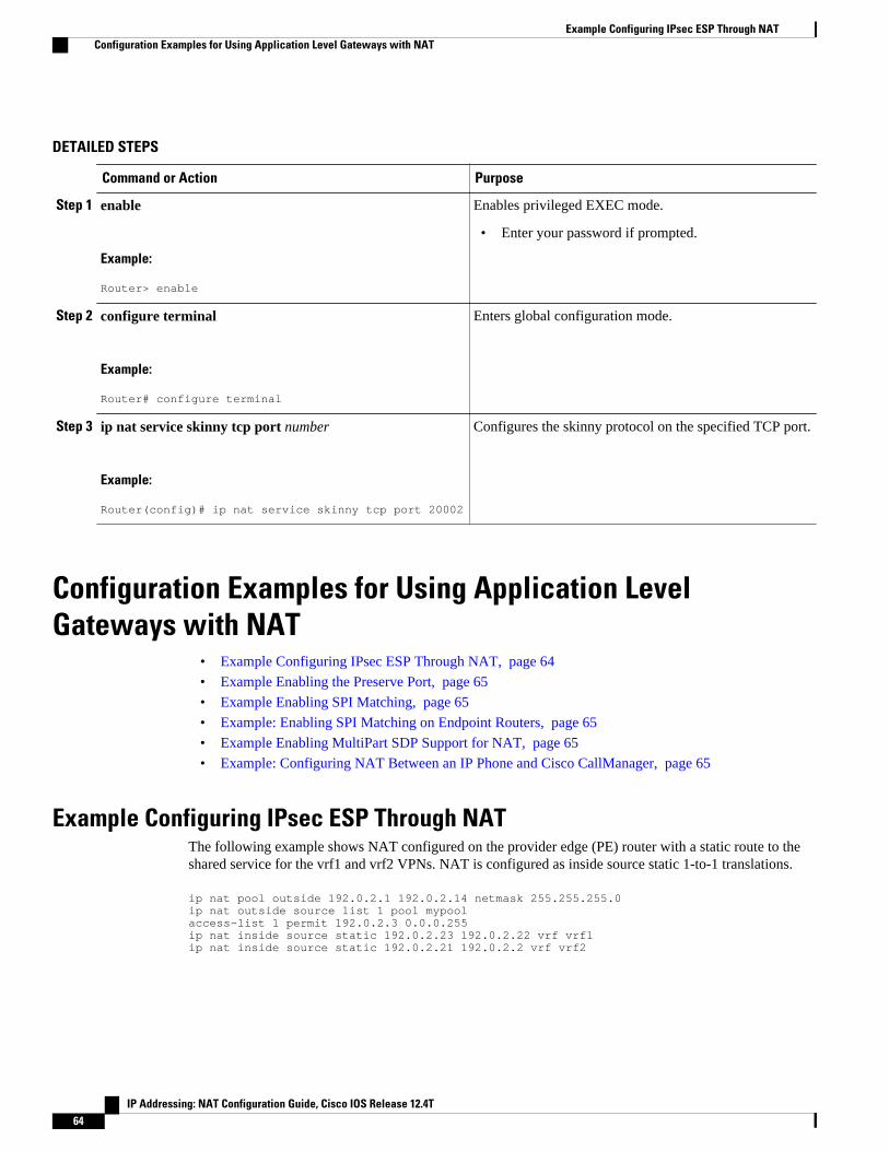
DETAILED STEPS
Command or Action Purpose
Step 1 enable
Example:
Router> enable
Enables privileged EXEC mode.
• Enter your password if prompted.
Step 2 configure terminal
Example:
Router# configure terminal
Enters global configuration mode.
Step 3 ip nat service skinny tcp port number
Example:
Router(config)# ip nat service skinny tcp port 20002
Configures the skinny protocol on the specified TCP port.
Configuration Examples for Using Application LevelGateways with NAT
• Example Configuring IPsec ESP Through NAT, page 64
• Example Enabling the Preserve Port, page 65
• Example Enabling SPI Matching, page 65
• Example: Enabling SPI Matching on Endpoint Routers, page 65
• Example Enabling MultiPart SDP Support for NAT, page 65
• Example: Configuring NAT Between an IP Phone and Cisco CallManager, page 65
Example Configuring IPsec ESP Through NATThe following example shows NAT configured on the provider edge (PE) router with a static route to theshared service for the vrf1 and vrf2 VPNs. NAT is configured as inside source static 1-to-1 translations.
ip nat pool outside 192.0.2.1 192.0.2.14 netmask 255.255.255.0ip nat outside source list 1 pool mypoolaccess-list 1 permit 192.0.2.3 0.0.0.255ip nat inside source static 192.0.2.23 192.0.2.22 vrf vrf1ip nat inside source static 192.0.2.21 192.0.2.2 vrf vrf2
Example Configuring IPsec ESP Through NAT Configuration Examples for Using Application Level Gateways with NAT
IP Addressing: NAT Configuration Guide, Cisco IOS Release 12.4T64

Example Enabling the Preserve PortThe following example shows how to configure TCP port 500 of the third-party concentrator. Access list10 is configured:
ip nat service list 10 IKE preserve-portaccess-list 10 permit 10.1.1.1
Example Enabling SPI MatchingThe following example shows how to enable SPI matching. Access list 10 is configured:
ip nat service list 10 ESP spi-matchaccess-list 10 permit 10.1.1.1
Example: Enabling SPI Matching on Endpoint Routerscrypto ipsec nat-transparency spi-matching
Example Enabling MultiPart SDP Support for NATThe following example shows how to enable multipart SDP support for NAT:
ip nat service allow-multipart
Example: Configuring NAT Between an IP Phone and Cisco CallManagerip nat service skinny tcp port 20002
Where to Go Next• To learn about NAT and configure NAT for IP address conservation, see the “Configuring NAT for IP
Address Conservation” module.• To verify monitor, and maintain NAT, see the “Monitoring and Maintaining NAT” module.• To integrate NAT with MPLS VPNs, see the “Integrating NAT with MPLS VPNs” module.• To configure NAT for high availability, see the “Configuring NAT for High Availability” module.
Additional ReferencesRelated Documents
Related Topic Document Title
Cisco IOS commands Cisco IOS Master Commands List, All Releases
Example Enabling the Preserve PortWhere to Go Next
IP Addressing: NAT Configuration Guide, Cisco IOS Release 12.4T 65
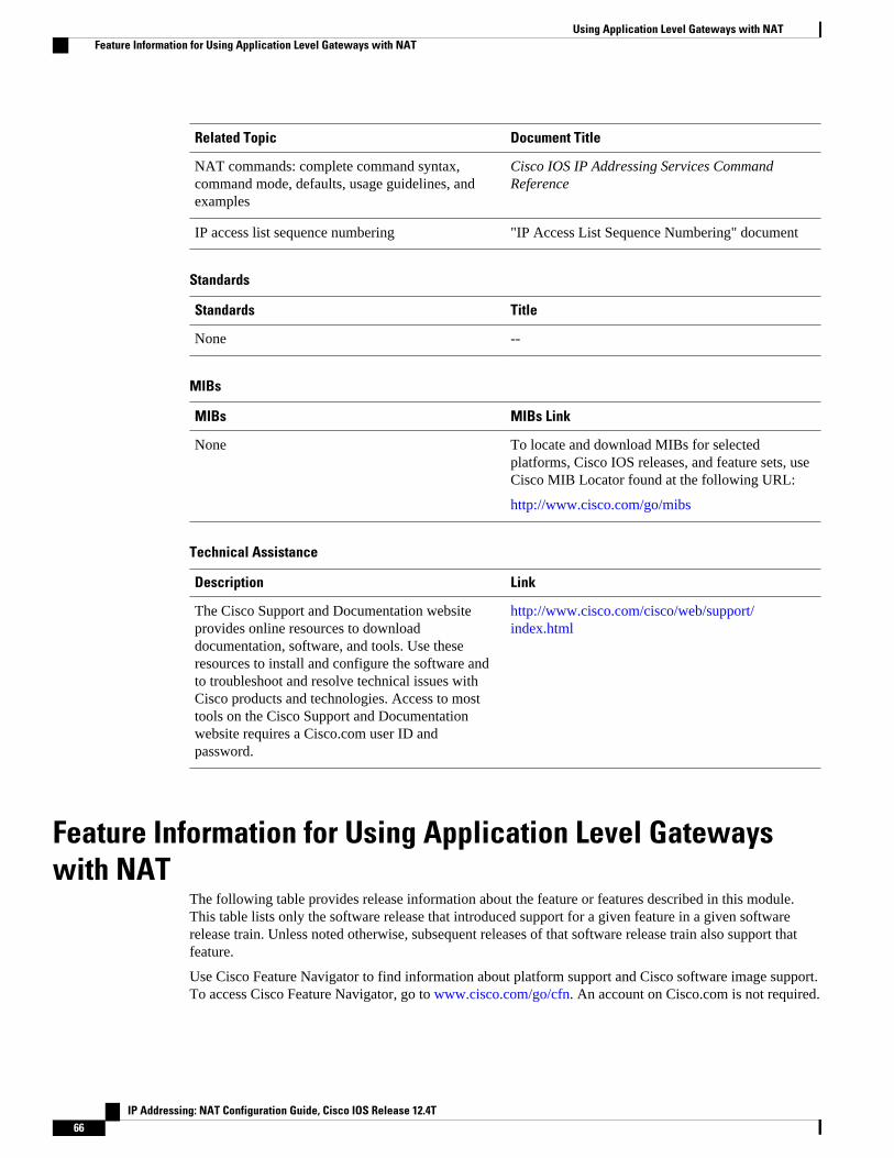
Related Topic Document Title
NAT commands: complete command syntax,command mode, defaults, usage guidelines, andexamples
Cisco IOS IP Addressing Services CommandReference
IP access list sequence numbering "IP Access List Sequence Numbering" document
Standards
Standards Title
None --
MIBs
MIBs MIBs Link
None To locate and download MIBs for selectedplatforms, Cisco IOS releases, and feature sets, useCisco MIB Locator found at the following URL:
http://www.cisco.com/go/mibs
Technical Assistance
Description Link
The Cisco Support and Documentation websiteprovides online resources to downloaddocumentation, software, and tools. Use theseresources to install and configure the software andto troubleshoot and resolve technical issues withCisco products and technologies. Access to mosttools on the Cisco Support and Documentationwebsite requires a Cisco.com user ID andpassword.
http://www.cisco.com/cisco/web/support/index.html
Feature Information for Using Application Level Gatewayswith NAT
The following table provides release information about the feature or features described in this module.This table lists only the software release that introduced support for a given feature in a given softwarerelease train. Unless noted otherwise, subsequent releases of that software release train also support thatfeature.
Use Cisco Feature Navigator to find information about platform support and Cisco software image support.To access Cisco Feature Navigator, go to www.cisco.com/go/cfn. An account on Cisco.com is not required.
Using Application Level Gateways with NAT Feature Information for Using Application Level Gateways with NAT
IP Addressing: NAT Configuration Guide, Cisco IOS Release 12.4T66
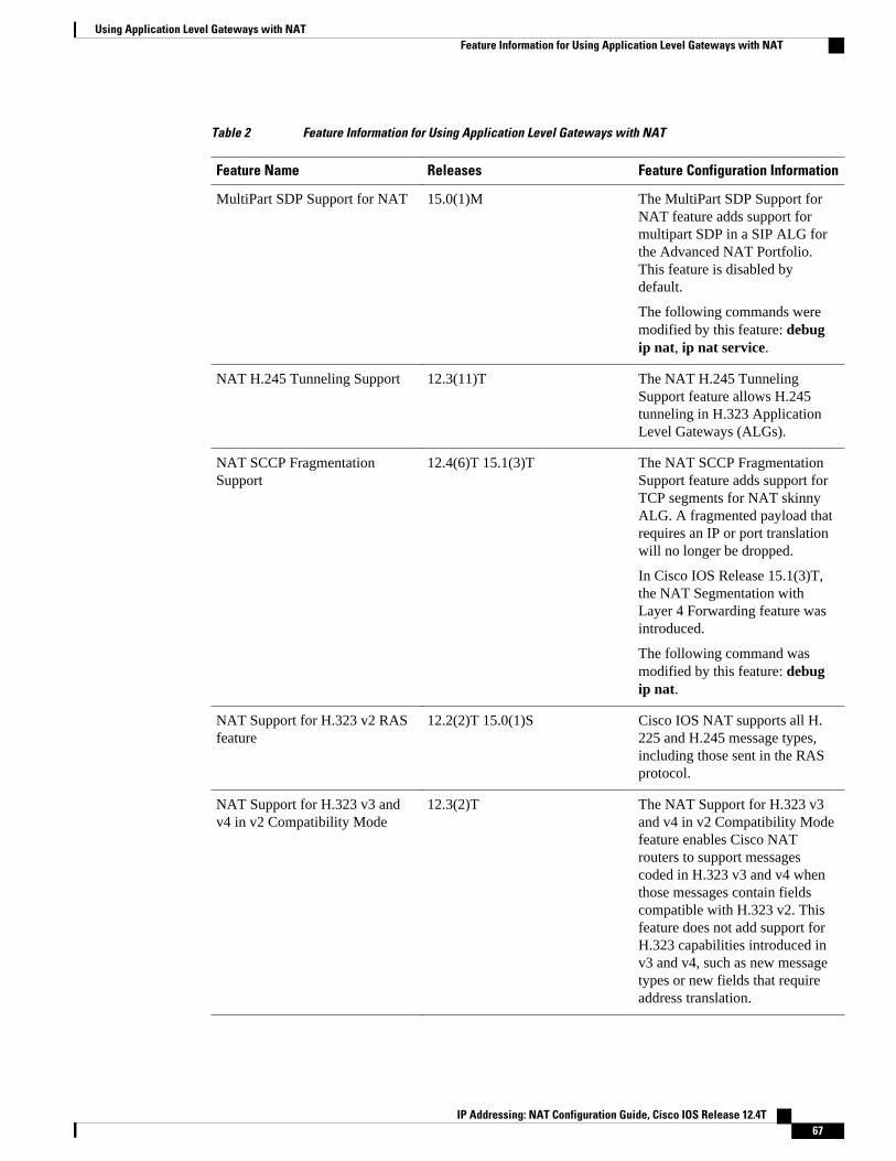
Table 2 Feature Information for Using Application Level Gateways with NAT
Feature Name Releases Feature Configuration Information
MultiPart SDP Support for NAT 15.0(1)M The MultiPart SDP Support forNAT feature adds support formultipart SDP in a SIP ALG forthe Advanced NAT Portfolio.This feature is disabled bydefault.
The following commands weremodified by this feature: debugip nat, ip nat service.
NAT H.245 Tunneling Support 12.3(11)T The NAT H.245 TunnelingSupport feature allows H.245tunneling in H.323 ApplicationLevel Gateways (ALGs).
NAT SCCP FragmentationSupport
12.4(6)T 15.1(3)T The NAT SCCP FragmentationSupport feature adds support forTCP segments for NAT skinnyALG. A fragmented payload thatrequires an IP or port translationwill no longer be dropped.
In Cisco IOS Release 15.1(3)T,the NAT Segmentation withLayer 4 Forwarding feature wasintroduced.
The following command wasmodified by this feature: debugip nat.
NAT Support for H.323 v2 RASfeature
12.2(2)T 15.0(1)S Cisco IOS NAT supports all H.225 and H.245 message types,including those sent in the RASprotocol.
NAT Support for H.323 v3 andv4 in v2 Compatibility Mode
12.3(2)T The NAT Support for H.323 v3and v4 in v2 Compatibility Modefeature enables Cisco NATrouters to support messagescoded in H.323 v3 and v4 whenthose messages contain fieldscompatible with H.323 v2. Thisfeature does not add support forH.323 capabilities introduced inv3 and v4, such as new messagetypes or new fields that requireaddress translation.
Using Application Level Gateways with NATFeature Information for Using Application Level Gateways with NAT
IP Addressing: NAT Configuration Guide, Cisco IOS Release 12.4T 67
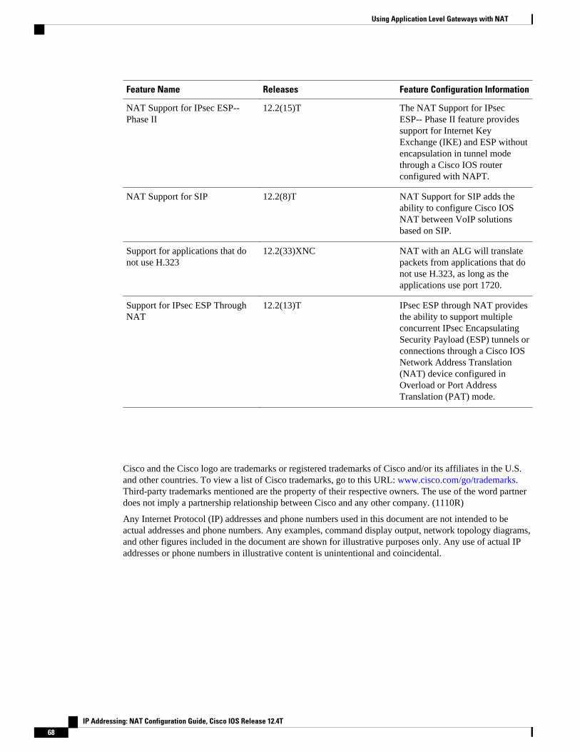
Feature Name Releases Feature Configuration Information
NAT Support for IPsec ESP--Phase II
12.2(15)T The NAT Support for IPsecESP-- Phase II feature providessupport for Internet KeyExchange (IKE) and ESP withoutencapsulation in tunnel modethrough a Cisco IOS routerconfigured with NAPT.
NAT Support for SIP 12.2(8)T NAT Support for SIP adds theability to configure Cisco IOSNAT between VoIP solutionsbased on SIP.
Support for applications that donot use H.323
12.2(33)XNC NAT with an ALG will translatepackets from applications that donot use H.323, as long as theapplications use port 1720.
Support for IPsec ESP ThroughNAT
12.2(13)T IPsec ESP through NAT providesthe ability to support multipleconcurrent IPsec EncapsulatingSecurity Payload (ESP) tunnels orconnections through a Cisco IOSNetwork Address Translation(NAT) device configured inOverload or Port AddressTranslation (PAT) mode.
Cisco and the Cisco logo are trademarks or registered trademarks of Cisco and/or its affiliates in the U.S.and other countries. To view a list of Cisco trademarks, go to this URL: www.cisco.com/go/trademarks.Third-party trademarks mentioned are the property of their respective owners. The use of the word partnerdoes not imply a partnership relationship between Cisco and any other company. (1110R)
Any Internet Protocol (IP) addresses and phone numbers used in this document are not intended to beactual addresses and phone numbers. Any examples, command display output, network topology diagrams,and other figures included in the document are shown for illustrative purposes only. Any use of actual IPaddresses or phone numbers in illustrative content is unintentional and coincidental.
Using Application Level Gateways with NAT
IP Addressing: NAT Configuration Guide, Cisco IOS Release 12.4T68
Configuring NAT for High Availability
This module contains procedures for configuring Network Address Translation (NAT) to support theincreasing need for highly resilient IP networks. This network resiliency is required where applicationconnectivity needs to continue unaffected by failures to links and routers at the NAT border.
• Finding Feature Information, page 69• Prerequisites for Configuring NAT for High Availability, page 69• Restrictions for Configuring NAT for High Availability, page 70• Information About Configuring NAT for High Availability, page 70• How to Configure NAT for High Availability, page 73• Configuration Example for NAT for High Availability, page 87• Additional References, page 89• Feature Information for Configuring NAT for High Availability, page 90
Finding Feature InformationYour software release may not support all the features documented in this module. For the latest featureinformation and caveats, see the release notes for your platform and software release. To find informationabout the features documented in this module, and to see a list of the releases in which each feature issupported, see the Feature Information Table at the end of this document.
Use Cisco Feature Navigator to find information about platform support and Cisco software image support.To access Cisco Feature Navigator, go to www.cisco.com/go/cfn. An account on Cisco.com is not required.
Prerequisites for Configuring NAT for High Availability• Before performing the tasks in this module, you should be familiar with the concepts described in the
“Configuring NAT for IP Address Conservation” module.• All access lists required for use with the tasks in this module should be configured prior to beginning
the configuration tasks. For information about how to configure an access list, see the “IP Access ListSequence Numbering" document.
Note If you specify an access list to use with a NAT command, NAT does not support the commonly usedpermit ip any any command in the access list.
IP Addressing: NAT Configuration Guide, Cisco IOS Release 12.4T 69

Restrictions for Configuring NAT for High Availability• Cisco has announced the End-of-Sale and End-of-Life for the Cisco IOS SNAT. For more information,
see the End-of-Sale and End-of-Life Announcement for the Cisco IOS Stateful Failover of NetworkAddress Translation (SNAT) document.
• The Address Resolution Protocol (ARP) queries are always replied to by the Hot Standby RoutingProtocol (HSRP) active router. If the active HSRP router fails upstream devices will point to the newHSRP active router and will not have an ARP entry pointing to the original active router, which mayno longer be available.
Information About Configuring NAT for High Availability• Stateful NAT, page 70
• NAT Stateful Failover for Asymmetric Outside-to-Inside ALG Support, page 70
• Interaction with HSRP, page 70
• Translation Group, page 71
• Address Resolution with ARP, page 71
• Stateful Failover for Asymmetric Outside-to-Inside Support, page 71
• Stateful Failover for ALGs, page 72
Stateful NATStateful NAT (SNAT) enables continuous service for dynamically mapped NAT sessions. Sessions that arestatically defined receive the benefit of redundancy without the need for SNAT. In the absence of SNAT,sessions that use dynamic NAT mappings would be severed in the event of a critical failure and would haveto be reestablished.
SNAT can be used with protocols that do not need payload translation.
NAT Stateful Failover for Asymmetric Outside-to-Inside ALG SupportNAT stateful failover for asymmetric outside-to-inside and Application Layer Gateway (ALG) supportimproves the ability to handle asymmetric paths by allowing multiple routing paths from outside-to-inside,and per-packet load balancing. This feature also provides seamless failover translated IP sessions withtraffic that includes embedded IP addressing such as Voice over IP, FTP, and Domain Name System (DNS)applications.
Interaction with HSRPSNAT can be configured to operate with the Hot Standby Routing Protocol (HSRP) to provide redundancy.Active and Standby state changes are managed by HSRP.
SNAT applies a more global context to the task of forwarding a particular datagram. Consideration is givento understanding the application state along with forwarding. Devices can take action to avoid potentialfailures that will have less impact on the flow and to the application that is transmitting data. Multiple NATrouters that share stateful context can work cooperatively and thereby increase service availability.
Stateful NAT Restrictions for Configuring NAT for High Availability
IP Addressing: NAT Configuration Guide, Cisco IOS Release 12.4T70

Translation GroupTwo or more network address translators function as a translation group. One member of the group handlestraffic requiring translation of IP address information. It also informs the backup translator of active flowsas they occur. The backup translator can then use information from the active translator to prepare duplicatetranslation table entries, and in the event that the active translator is hindered by a critical failure, the trafficcan rapidly be switched to the backup. The traffic flow continues since the same network addresstranslations are used, and the state of those translations has been previously defined.
Address Resolution with ARPA device in IP can have both a local address (which uniquely identifies the device on its local segment orLAN) and a network address (which identifies the network to which the device belongs). The local addressis more properly known as a data link address because it is contained in the data link layer (Layer 2 of theOSI model) part of the packet header and is read by data-link devices (bridges and all device interfaces, forexample). The local address is referred to as the MAC address, because the MAC sub-layer within the datalink layer processes addresses for the layer.
To communicate with a device on Ethernet, for example, the Cisco IOS software first must determine the48-bit MAC or local data-link address of that device. The process of determining the local data-link addressfrom an IP address is called address resolution. The process of determining the IP address from a localdata-link address is called reverse address resolution.
The software uses three forms of address resolution: Address Resolution Protocol (ARP), proxy ARP, andProbe (similar to ARP). The software also uses the Reverse Address Resolution Protocol (RARP). ARP,proxy ARP, and RARP are defined in RFCs 826, 1027, and 903, respectively. Probe is a protocoldeveloped by the Hewlett-Packard Company (HP) for use on IEEE-802.3 networks.
ARP is used to associate IP addresses with media or MAC addresses. Taking an IP address as input, ARPdetermines the associated media address. Once a media or MAC address is determined, the IP address ormedia address association is stored in an ARP cache for rapid retrieval. Then the IP datagram isencapsulated in a link-layer frame and sent over the network. Encapsulation of IP datagrams and ARPrequests and replies on IEEE 802 networks other than Ethernet is specified by the Subnetwork AccessProtocol (SNAP).
Stateful Failover for Asymmetric Outside-to-Inside SupportStateful failover for asymmetric outside-to-inside support enables two NAT routers to participate in aprimary/backup design. One of the routers is elected as the primary NAT router and a second router acts asthe backup router. As traffic is actively translated by the primary NAT router it updates the backup NATrouter with the NAT translation state from NAT translation table entries. If the primary NAT router fails oris out of service, the backup NAT router will automatically take over. When the primary comes back intoservice it will take over and request an update from the backup NAT router. Return traffic is handled byeither the primary or the backup NAT translator and NAT translation integrity is preserved.
When the backup NAT router receives asymmetric IP traffic and performs NAT of the packets, it willupdate the primary NAT router to ensure both the primary and backup NAT translation tables remainsynchronized.
Translation GroupInformation About Configuring NAT for High Availability
IP Addressing: NAT Configuration Guide, Cisco IOS Release 12.4T 71

The figure below shows a typical configuration that uses the NAT Stateful Failover for AsymmetricOutside-to-Inside and ALG Support feature.
Figure 6 Stateful NAT Asymmetric Outside-to-Inside Support
103787
HSRP Virtual IP
192.168.123.1
.2 .3
192.168.123.4
Primary NAT Backup NAT
192.168.123.5
Primary NAT Backup NAT
192.168.123.5
IL: 192.168.123.4:1001 IG: 11.1.1.1:1001 OG: 12.1.1.1:80 OL: 12.1.1.1:80
Dynamic NAT Entry
IL: 192.168.123.4:1001 IG: 11.1.1.1:1001 OG: 12.1.1.1:80 OL: 12.1.1.1:80
Dynamic NAT Entry
SP Network A SP Network B
Stateful Failover for ALGsThe stateful failover embedded addressing enhancement allows the secondary or backup NAT router toproperly handle NAT and delivery of IP traffic. NAT inspects all IP traffic entering interfaces that havebeen configured with the NAT feature. The inspection consists of matching the incoming traffic against aset of translations rules and performs an address translation if a match occurs. The following are examples:
• Matching a source address range• Matching a specific destination address range• Matching a list of applications known to NAT that might require a specific source port for control
plane negotiation, or embedded source IP addresses within the application protocol
Some of the applications and protocols that embed source port or IP address information include:
• H.323 Registration, Admission, and Status (RAS) Protocol• DNS queries• NetMeeting Internet Locator Server (ILS)• Internet Control Message Protocol (ICMP)• Simple Mail Transfer Protocol (SMTP)• Point-to-Point Tunneling Protocol (PPTP)• Network File System (NFS)
A complete list of current ALG protocols supported by Cisco IOS NAT can be found at
http://www.cisco.com/en/US/tech/tk648/tk361/tech_brief09186a00801af2b9.html
Stateful Failover for ALGs Information About Configuring NAT for High Availability
IP Addressing: NAT Configuration Guide, Cisco IOS Release 12.4T72

How to Configure NAT for High Availability• Configuring the Stateful Failover of NAT, page 73
• Configuring NAT Stateful Failover for Asymmetric Outside-to-Inside and ALG Support, page 78
• Configuring NAT Static Mapping Support for HSRP, page 83
Configuring the Stateful Failover of NATThe NAT Stateful Failover of Network Address Translation feature represents Phase 1 of the statefulfailover capability. It introduces support for two or more network address translators to function as atranslation group. A backup router running NAT provides translation services in the event the activetranslator fails. Protocols that do not need payload translations, such as HTTP and telnet, are supported bystateful NAT (SNAT).
This section contains the following procedures:
• Restrictions for Configuring Stateful Failover of NAT, page 73
• Configuring SNAT with HSRP, page 73
• Configuring SNAT on the Primary (Active) Router, page 75
• Configuring SNAT on the Backup (Standby) Router, page 77
Restrictions for Configuring Stateful Failover of NATThe following applications and protocols are not supported in Phase I:
• Application Level Gateway (ALG)• FTP• NetMeeting Directory (ILS)• RAS• SIP• Skinny• TFTP• Asymmetrical routing
SNAT features are not backward compatible. See "Feature Information for Configuring NAT for HighAvailability" and “Scalability for Stateful NAT” for information on SNAT features and the releases inwhich they were introduced.
Configuring SNAT with HSRPPerform this task to configure Stateful NAT using HSRP to provide router backup facilities.
Note This task must be performed on both the active and the standby routers.
Configuring the Stateful Failover of NATHow to Configure NAT for High Availability
IP Addressing: NAT Configuration Guide, Cisco IOS Release 12.4T 73

SUMMARY STEPS
1. enable
2. configure terminal
3. interface type number
4. standby [group-name] ip[ip-address[secondary]]
5. exit
6. ip nat stateful id id-number {redundancy name mapping-id map-number}
7. ip nat pool name start-ip end-ip prefix-length prefix-length
8. ip nat inside source {route-map name pool pool-name mapping-id map-number} [overload]
9. exit
10. show ip snat distributed verbose
DETAILED STEPS
Command or Action Purpose
Step 1 enable
Example:
Router> enable
Enables higher privilege levels, such asprivileged EXEC mode.
• Enter your password if prompted.
Step 2 configure terminal
Example:
Router# configure terminal
Enters global configuration mode.
Step 3 interface type number
Example:
Router(config)# interface ethernet 1/1
Enters interface configuration mode.
Step 4 standby [group-name] ip[ip-address[secondary]]
Example:
Router(config-if)# standby SNATHSRP ip 10.1.1.1
Enables the HSRP protocol.
Step 5 exit
Example:
Router(config-if)# exit
Returns to global configuration mode.
Configuring NAT for High Availability Configuring SNAT with HSRP
IP Addressing: NAT Configuration Guide, Cisco IOS Release 12.4T74

Command or Action Purpose
Step 6 ip nat stateful id id-number {redundancy name mapping-id map-number}
Example:
Router(config)# ip nat stateful id 1 redundancy snathsrp mapping-id 10
Specifies SNAT on routers configured forHSRP.
Step 7 ip nat pool name start-ip end-ip prefix-length prefix-length
Example:
Router(config)# ip nat pool snatpool1 10.1.1.1 10.1.1.9 prefix-length 24
Defines a pool of IP addresses.
Step 8 ip nat inside source {route-map name pool pool-name mapping-id map-number} [overload]
Example:
Router(config)# ip nat inside source route-map rm-101 pool snatpool1 mapping-id 10 overload
Enables stateful NAT for the HSRPtranslation group.
Step 9 exit
Example:
Router(config)# exit
Returns to privileged EXEC mode.
Step 10 show ip snat distributed verbose
Example:
Router# show ip snat distributed verbose
(Optional) Displays active stateful NATtranslations.
Configuring SNAT on the Primary (Active) RouterPerform this task to manually configure your primary SNAT router. When you have completed this task,perform the steps in "Configuring SNAT on the Backup (Standby) Router".
Configuring NAT for High AvailabilityConfiguring SNAT on the Primary (Active) Router
IP Addressing: NAT Configuration Guide, Cisco IOS Release 12.4T 75

SUMMARY STEPS
1. enable
2. configure terminal
3. ip nat stateful id id-number primary ip-address peer ip-address mapping-id map-number
4. ip nat pool name start-ip end-ip prefix-length prefix-length
5. ip nat inside source route-map name pool pool-name mapping-id map-number [overload]
6. exit
7. show ip snat distributed verbose
DETAILED STEPS
Command or Action Purpose
Step 1 enable
Example:
Router> enable
Enables higher privilege levels, such asprivileged EXEC mode.
• Enter your password if prompted.
Step 2 configure terminal
Example:
Router# configure terminal
Enters global configuration mode.
Step 3 ip nat stateful id id-number primary ip-address peer ip-address mapping-idmap-number
Example:
Router(config)# ip nat stateful id 1 primary 10.10.10.10 peer 10.22.22.22 mapping-id 10
Specifies stateful NAT on the primaryrouter.
Step 4 ip nat pool name start-ip end-ip prefix-length prefix-length
Example:
Router(config)# ip nat pool SNATPOOL1 10.1.1.1 10.1.1.9 prefix-length 24
Defines a pool of IP addresses.
Step 5 ip nat inside source route-map name pool pool-name mapping-id map-number [overload]
Example:
Router(config)# ip nat inside source route-map rm-101 pool snatpool1 mapping-id 10 overload
Enables stateful NAT for the HSRPtranslation group.
Configuring NAT for High Availability Configuring SNAT on the Primary (Active) Router
IP Addressing: NAT Configuration Guide, Cisco IOS Release 12.4T76
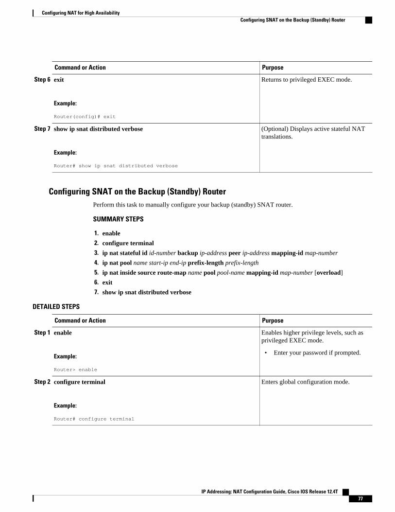
Command or Action Purpose
Step 6 exit
Example:
Router(config)# exit
Returns to privileged EXEC mode.
Step 7 show ip snat distributed verbose
Example:
Router# show ip snat distributed verbose
(Optional) Displays active stateful NATtranslations.
Configuring SNAT on the Backup (Standby) RouterPerform this task to manually configure your backup (standby) SNAT router.
SUMMARY STEPS
1. enable
2. configure terminal
3. ip nat stateful id id-number backup ip-address peer ip-address mapping-id map-number
4. ip nat pool name start-ip end-ip prefix-length prefix-length
5. ip nat inside source route-map name pool pool-name mapping-id map-number [overload]
6. exit
7. show ip snat distributed verbose
DETAILED STEPS
Command or Action Purpose
Step 1 enable
Example:
Router> enable
Enables higher privilege levels, such asprivileged EXEC mode.
• Enter your password if prompted.
Step 2 configure terminal
Example:
Router# configure terminal
Enters global configuration mode.
Configuring NAT for High AvailabilityConfiguring SNAT on the Backup (Standby) Router
IP Addressing: NAT Configuration Guide, Cisco IOS Release 12.4T 77

Command or Action Purpose
Step 3 ip nat stateful id id-number backup ip-address peer ip-address mapping-idmap-number
Example:
Router(config)# ip nat stateful id 1 backup 10.2.2.2 peer 10.10.10.10 mapping-id 10
Specifies stateful NAT on the backuprouter.
Step 4 ip nat pool name start-ip end-ip prefix-length prefix-length
Example:
Router(config)# ip nat pool SNATPOOL1 10.1.1.1 10.1.1.9 prefix-length 24
Defines a pool of IP addresses.
Step 5 ip nat inside source route-map name pool pool-name mapping-id map-number [overload]
Example:
Router(config)# ip nat inside source route-map rm-101 pool snatpool1 mapping-id 10 overload
Enables stateful NAT for the HSRPtranslation group.
Step 6 exit
Example:
Router(config)# exit
Returns to privileged EXEC mode.
Step 7 show ip snat distributed verbose
Example:
Router# show ip snat distributed verbose
(Optional) Displays active stateful NATtranslations.
Configuring NAT Stateful Failover for Asymmetric Outside-to-Inside andALG Support
Stateful NAT Phase I required all sessions to pass through the primary NAT router that controlled the NATtranslation entries unless the primary NAT router was unavailable. This requirement assured integrity of thetranslation information by guarding against the possibility of some packets relevant to NAT session controlfrom traversing the backup without the primary being aware of it. Without synchronized IP sessions NATeventually times out the IP session entries and the result is IP session states that are out of sequence.
This section contains the following procedures:
• Prerequisites for Configuring the NAT Stateful Failover for Asymmetric Outside-to-Inside and ALGSupport Feature, page 79
Configuring NAT Stateful Failover for Asymmetric Outside-to-Inside and ALG Support Configuring SNAT on the Backup (Standby) Router
IP Addressing: NAT Configuration Guide, Cisco IOS Release 12.4T78

• Configuring SNAT with HSRP, page 79
• Configuring SNAT Primary Backup, page 81
Prerequisites for Configuring the NAT Stateful Failover for Asymmetric Outside-to-Insideand ALG Support Feature
Each router must have the same Network Address Translation (NAT) configurations.
The stateful failover asymmetric outside-to-inside enhancement provides the following benefits:
• Ability to support multiple routing paths from outside-to-inside• Ability to handle per-packet load balancing of asymmetric routing from outside-to-inside
Configuring SNAT with HSRPTo configure your Hot Standby Router Protocol (HSRP) router with Stateful Network Address Translation(SNAT), use the following commands:
SUMMARY STEPS
1. enable
2. configure terminal
3. interface type number
4. standby [group-name] ip[ip-address[secondary]]
5. exit
6. ip nat stateful id ip-address redundancy group-name mapping-id map-id
7. ip nat pool name start-ip end-ip prefix-length prefix-length
8. ip nat inside source static route-map name pool pool-name mapping-id map-id [overload]
9. ip nat inside destination list number pool name mapping-id map-id
10. ip nat outside source static global-ip local-ip extendable mapping-id map-id
11. end
DETAILED STEPS
Command or Action Purpose
Step 1 enable
Example:
Router> enable
Enables privileged EXEC mode.
• Enter your password if prompted.
Step 2 configure terminal
Example:
Router# configure terminal
Enters global configuration mode.
Configuring NAT for High AvailabilityPrerequisites for Configuring the NAT Stateful Failover for Asymmetric Outside-to-Inside and ALG Support Feature
IP Addressing: NAT Configuration Guide, Cisco IOS Release 12.4T 79

Command or Action Purpose
Step 3 interface type number
Example:
Router(config)# interface ethernet 1/1
Enters interface configuration mode.
Step 4 standby [group-name] ip[ip-address[secondary]]
Example:
Router(config-if)# standby SNATHSRP ip 11.1.1.1 secondary
Enables the HSRP protocol.
Step 5 exit
Example:
Router(config-if)# exit
Returns to global configuration mode.
Step 6 ip nat stateful id ip-address redundancy group-name mapping-id map-id
Example:
Router(config)# ip nat stateful id 1 redundancy snathsrp mapping-id 10
Specifies SNAT on routers configured forHSRP.
Step 7 ip nat pool name start-ip end-ip prefix-length prefix-length
Example:
Router(config)# ip nat pool snatpool1 11.1.1.1 11.1.1.9 prefix-length 24
Defines a pool of IP addresses.
Step 8 ip nat inside source static route-map name pool pool-name mapping-idmap-id [overload]
Example:
Router(config)# ip nat inside source static route-map rm-101 pool snatpool2 mapping-id 10 overload
Enables stateful NAT for the HSRPtranslation group.
Step 9 ip nat inside destination list number pool name mapping-id map-id
Example:
Router(config)# ip nat inside destination list 1 pool snatpool2 mapping-id 10
Enables the local SNAT router to distribute aparticular set of locally created entries to apeer SNAT router.
Configuring NAT for High Availability Configuring SNAT with HSRP
IP Addressing: NAT Configuration Guide, Cisco IOS Release 12.4T80

Command or Action Purpose
Step 10 ip nat outside source static global-ip local-ip extendable mapping-idmap-id
Example:
Router(config)# ip nat outside source static 1.1.1.1 2.2.2.2 extendable mapping-id 10
Enables stateful NAT for the HSRPtranslation group.
Step 11 end
Example:
Router(config)# end
Exits global configuration mode.
• Use the end command to save yourconfiguration and leave configurationmode.
Configuring SNAT Primary BackupUse the following commands to enable the NAT Stateful Failover for Asymmetric Outside-to-Inside andALG Support feature:
SUMMARY STEPS
1. enable
2. configure terminal
3. ip nat stateful id id-number primary ip-address peer ip-address mapping-id map-id
4. ip nat pool name start-ip end-ip prefix-length prefix-length
5. ip nat inside source static route-map name pool pool-name mapping-id map-id [overload]
6. ip nat inside destination list number pool name mapping-id map-id
7. ip nat outside source Static global-ip local-ip extendable mapping-id map-id
8. end
DETAILED STEPS
Command or Action Purpose
Step 1 enable
Example:
Router> enable
Enables privileged EXEC mode.
• Enter your password if prompted.
Step 2 configure terminal
Example:
Router# configure terminal
Enters global configuration mode.
Configuring NAT for High AvailabilityConfiguring SNAT Primary Backup
IP Addressing: NAT Configuration Guide, Cisco IOS Release 12.4T 81

Command or Action Purpose
Step 3 ip nat stateful id id-number primary ip-address peer ip-address mapping-id map-id
Example:
Router(config)# ip nat stateful id 1 primary 1.1.1.1 peer 2.2.2.2 mapping-id 10
Specifies stateful NAT on the primary router.
Step 4 ip nat pool name start-ip end-ip prefix-length prefix-length
Example:
Router(config)# parser config cache interface
Defines a pool of IP addresses.
Step 5 ip nat inside source static route-map name pool pool-name mapping-id map-id [overload]
Example:
Router(config)# ip nat inside source static route-map rm-101 pool snatpool2 mapping-id 10 overload
Enables stateful NAT of the inside source addressto distribute a particular set of locally createdentries to a peer SNAT router.
Step 6 ip nat inside destination list number pool name mapping-id map-id
Example:
Router(config)# ip nat inside destination list 1 pool snatpool2 mapping-id 10 overload
Defines the inside destination address that enablesthe local SNAT router to distribute locally createdentries to a peer SNAT router.
Step 7 ip nat outside source Static global-ip local-ip extendablemapping-id map-id
Example:
Router(config)# ip nat outside source static 1.1.1.1 2.2.2.2 extendable mapping-id 10
Enables stateful NAT of the outside source addressto distribute a particular set of locally createdentries to a peer SNAT router.
Step 8 end
Example:
Router(config)# end
Exits global configuration mode.
• Use the end command to save yourconfiguration and leave configuration mode.
Configuring NAT for High Availability Configuring SNAT Primary Backup
IP Addressing: NAT Configuration Guide, Cisco IOS Release 12.4T82
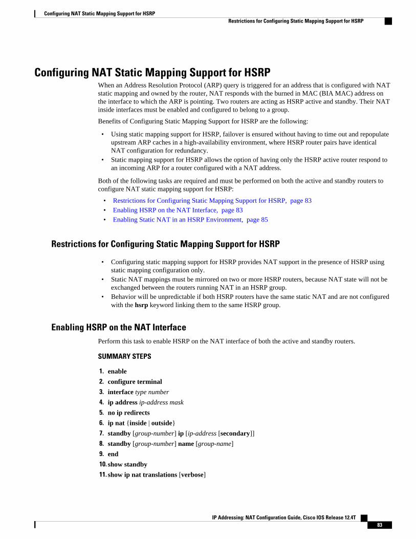
Configuring NAT Static Mapping Support for HSRPWhen an Address Resolution Protocol (ARP) query is triggered for an address that is configured with NATstatic mapping and owned by the router, NAT responds with the burned in MAC (BIA MAC) address onthe interface to which the ARP is pointing. Two routers are acting as HSRP active and standby. Their NATinside interfaces must be enabled and configured to belong to a group.
Benefits of Configuring Static Mapping Support for HSRP are the following:
• Using static mapping support for HSRP, failover is ensured without having to time out and repopulateupstream ARP caches in a high-availability environment, where HSRP router pairs have identicalNAT configuration for redundancy.
• Static mapping support for HSRP allows the option of having only the HSRP active router respond toan incoming ARP for a router configured with a NAT address.
Both of the following tasks are required and must be performed on both the active and standby routers toconfigure NAT static mapping support for HSRP:
• Restrictions for Configuring Static Mapping Support for HSRP, page 83
• Enabling HSRP on the NAT Interface, page 83
• Enabling Static NAT in an HSRP Environment, page 85
Restrictions for Configuring Static Mapping Support for HSRP
• Configuring static mapping support for HSRP provides NAT support in the presence of HSRP usingstatic mapping configuration only.
• Static NAT mappings must be mirrored on two or more HSRP routers, because NAT state will not beexchanged between the routers running NAT in an HSRP group.
• Behavior will be unpredictable if both HSRP routers have the same static NAT and are not configuredwith the hsrp keyword linking them to the same HSRP group.
Enabling HSRP on the NAT InterfacePerform this task to enable HSRP on the NAT interface of both the active and standby routers.
SUMMARY STEPS
1. enable
2. configure terminal
3. interface type number
4. ip address ip-address mask
5. no ip redirects
6. ip nat {inside | outside}
7. standby [group-number] ip [ip-address [secondary]]
8. standby [group-number] name [group-name]
9. end
10. show standby
11. show ip nat translations [verbose]
Configuring NAT Static Mapping Support for HSRPRestrictions for Configuring Static Mapping Support for HSRP
IP Addressing: NAT Configuration Guide, Cisco IOS Release 12.4T 83
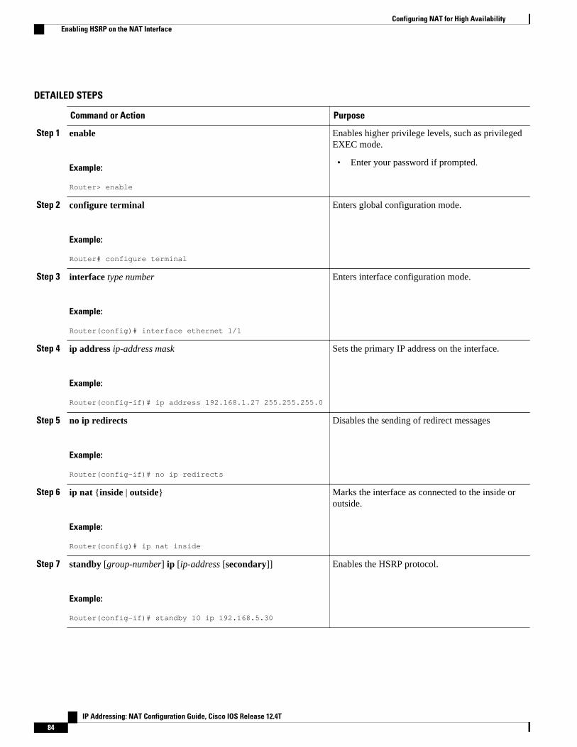
DETAILED STEPS
Command or Action Purpose
Step 1 enable
Example:
Router> enable
Enables higher privilege levels, such as privilegedEXEC mode.
• Enter your password if prompted.
Step 2 configure terminal
Example:
Router# configure terminal
Enters global configuration mode.
Step 3 interface type number
Example:
Router(config)# interface ethernet 1/1
Enters interface configuration mode.
Step 4 ip address ip-address mask
Example:
Router(config-if)# ip address 192.168.1.27 255.255.255.0
Sets the primary IP address on the interface.
Step 5 no ip redirects
Example:
Router(config-if)# no ip redirects
Disables the sending of redirect messages
Step 6 ip nat {inside | outside}
Example:
Router(config)# ip nat inside
Marks the interface as connected to the inside oroutside.
Step 7 standby [group-number] ip [ip-address [secondary]]
Example:
Router(config-if)# standby 10 ip 192.168.5.30
Enables the HSRP protocol.
Configuring NAT for High Availability Enabling HSRP on the NAT Interface
IP Addressing: NAT Configuration Guide, Cisco IOS Release 12.4T84

Command or Action Purpose
Step 8 standby [group-number] name [group-name]
Example:
Router(config-if)# standby 10 name HSRP1
Sets the HSRP group name.
Step 9 end
Example:
Router(config-if)# exit
Returns to privileged EXEC mode.
Step 10 show standby
Example:
Router# show standby
(Optional) Displays HSRP information
Step 11 show ip nat translations [verbose]
Example:
Router# show ip nat translations verbose
(Optional) Displays active NAT translations.
• What to Do Next, page 85
What to Do Next
Go to the next section and enable static NAT in the HSRP environment.
Enabling Static NAT in an HSRP EnvironmentTo enable static mapping support with HRSP for high availability, perform this task on both the active andstandby routers.
SUMMARY STEPS
1. enable
2. configure terminal
3. ip nat inside source {list {access-list-number | access-list-name} pool pool-name} [overload] | staticlocal-ip global-ip redundancy group-name}
4. ip nat outside source {list {access-list-number | access-list-name} pool pool-name} [overload] | staticlocal-ip global-ip redundancy group-name}
5. exit
6. show ip nat translations [verbose]
Configuring NAT for High AvailabilityWhat to Do Next
IP Addressing: NAT Configuration Guide, Cisco IOS Release 12.4T 85
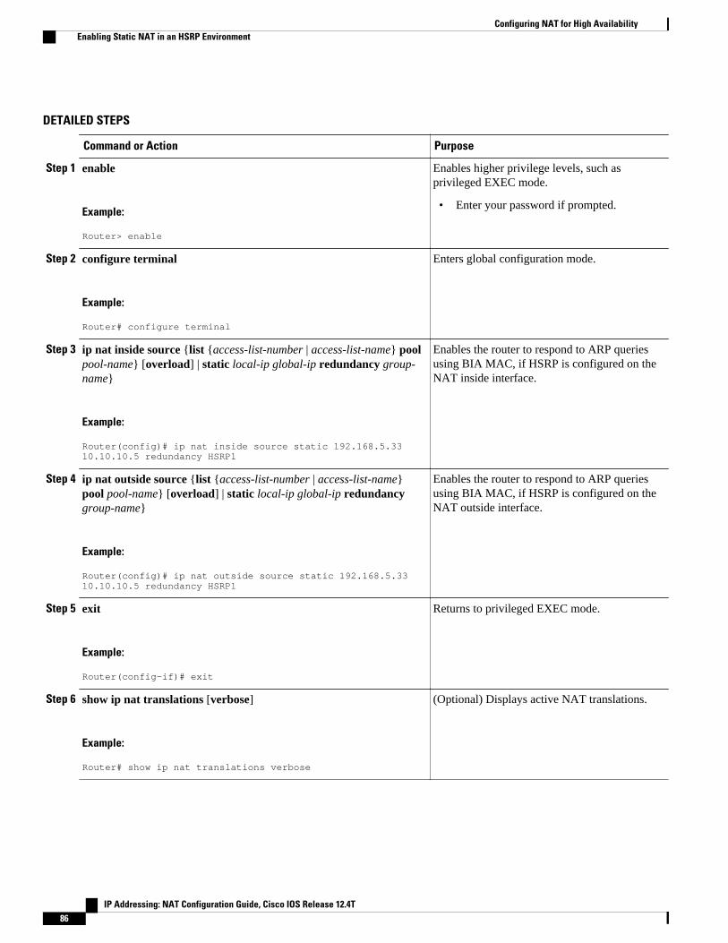
DETAILED STEPS
Command or Action Purpose
Step 1 enable
Example:
Router> enable
Enables higher privilege levels, such asprivileged EXEC mode.
• Enter your password if prompted.
Step 2 configure terminal
Example:
Router# configure terminal
Enters global configuration mode.
Step 3 ip nat inside source {list {access-list-number | access-list-name} poolpool-name} [overload] | static local-ip global-ip redundancy group-name}
Example:
Router(config)# ip nat inside source static 192.168.5.33 10.10.10.5 redundancy HSRP1
Enables the router to respond to ARP queriesusing BIA MAC, if HSRP is configured on theNAT inside interface.
Step 4 ip nat outside source {list {access-list-number | access-list-name}pool pool-name} [overload] | static local-ip global-ip redundancygroup-name}
Example:
Router(config)# ip nat outside source static 192.168.5.33 10.10.10.5 redundancy HSRP1
Enables the router to respond to ARP queriesusing BIA MAC, if HSRP is configured on theNAT outside interface.
Step 5 exit
Example:
Router(config-if)# exit
Returns to privileged EXEC mode.
Step 6 show ip nat translations [verbose]
Example:
Router# show ip nat translations verbose
(Optional) Displays active NAT translations.
Configuring NAT for High Availability Enabling Static NAT in an HSRP Environment
IP Addressing: NAT Configuration Guide, Cisco IOS Release 12.4T86
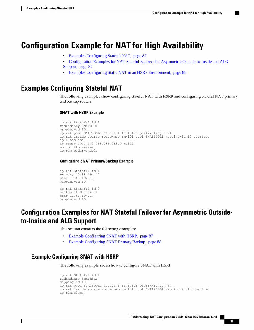
Configuration Example for NAT for High Availability• Examples Configuring Stateful NAT, page 87
• Configuration Examples for NAT Stateful Failover for Asymmetric Outside-to-Inside and ALGSupport, page 87
• Examples Configuring Static NAT in an HSRP Environment, page 88
Examples Configuring Stateful NATThe following examples show configuring stateful NAT with HSRP and configuring stateful NAT primaryand backup routers.
SNAT with HSRP Example
ip nat Stateful id 1redundancy SNATHSRPmapping-id 10ip nat pool SNATPOOL1 10.1.1.1 10.1.1.9 prefix-length 24ip nat inside source route-map rm-101 pool SNATPOOL1 mapping-id 10 overloadip classlessip route 10.1.1.0 255.255.255.0 Null0no ip http serverip pim bidir-enable
Configuring SNAT Primary/Backup Example
ip nat Stateful id 1primary 10.88.194.17peer 10.88.194.18mapping-id 10!ip nat Stateful id 2backup 10.88.194.18peer 10.88.194.17mapping-id 10
Configuration Examples for NAT Stateful Failover for Asymmetric Outside-to-Inside and ALG Support
This section contains the following examples:
• Example Configuring SNAT with HSRP, page 87
• Example Configuring SNAT Primary Backup, page 88
Example Configuring SNAT with HSRPThe following example shows how to configure SNAT with HSRP.
ip nat Stateful id 1redundancy SNATHSRPmapping-id 10ip nat pool SNATPOOL1 11.1.1.1 11.1.1.9 prefix-length 24ip nat inside source route-map rm-101 pool SNATPOOL1 mapping-id 10 overloadip classless
Examples Configuring Stateful NATConfiguration Example for NAT for High Availability
IP Addressing: NAT Configuration Guide, Cisco IOS Release 12.4T 87
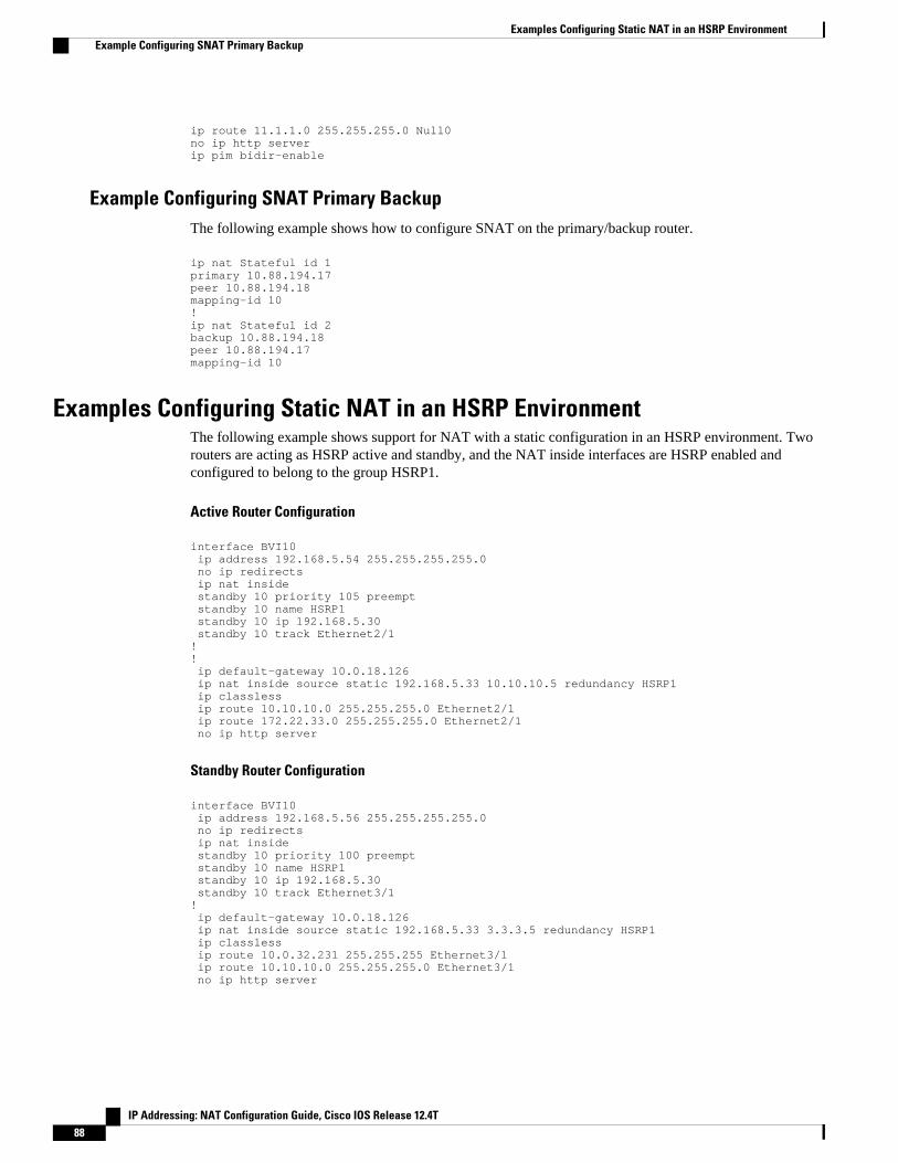
ip route 11.1.1.0 255.255.255.0 Null0no ip http serverip pim bidir-enable
Example Configuring SNAT Primary BackupThe following example shows how to configure SNAT on the primary/backup router.
ip nat Stateful id 1primary 10.88.194.17peer 10.88.194.18mapping-id 10!ip nat Stateful id 2backup 10.88.194.18peer 10.88.194.17mapping-id 10
Examples Configuring Static NAT in an HSRP EnvironmentThe following example shows support for NAT with a static configuration in an HSRP environment. Tworouters are acting as HSRP active and standby, and the NAT inside interfaces are HSRP enabled andconfigured to belong to the group HSRP1.
Active Router Configuration
interface BVI10 ip address 192.168.5.54 255.255.255.255.0 no ip redirects ip nat inside standby 10 priority 105 preempt standby 10 name HSRP1 standby 10 ip 192.168.5.30 standby 10 track Ethernet2/1 ! ! ip default-gateway 10.0.18.126 ip nat inside source static 192.168.5.33 10.10.10.5 redundancy HSRP1 ip classless ip route 10.10.10.0 255.255.255.0 Ethernet2/1 ip route 172.22.33.0 255.255.255.0 Ethernet2/1 no ip http server
Standby Router Configuration
interface BVI10 ip address 192.168.5.56 255.255.255.255.0 no ip redirects ip nat inside standby 10 priority 100 preempt standby 10 name HSRP1 standby 10 ip 192.168.5.30 standby 10 track Ethernet3/1 ! ip default-gateway 10.0.18.126 ip nat inside source static 192.168.5.33 3.3.3.5 redundancy HSRP1 ip classless ip route 10.0.32.231 255.255.255 Ethernet3/1 ip route 10.10.10.0 255.255.255.0 Ethernet3/1 no ip http server
Examples Configuring Static NAT in an HSRP Environment Example Configuring SNAT Primary Backup
IP Addressing: NAT Configuration Guide, Cisco IOS Release 12.4T88

Additional ReferencesRelated Documents
Related Topic Document Title
Cisco IOS commands Cisco IOS Master Commands List, All Releases
NAT commands: complete command syntax,command mode, command history, usageguidelines, and examples
Cisco IOS IP Addressing Services CommandReference
IP Access List Sequence Numbering IP Access List Sequence Numbering document
NAT configuration tasks “Configuring NAT for IP Address Conservation”module
NAT maintenance “Monitoring and Maintaining NAT” module
Using NAT with MPLS VPNs “Integrating NAT with MPLS VPNs” module
Standards
Standards Title
None
MIBs
MIBs MIBs Link
• None To locate and download MIBs for selectedplatforms, Cisco IOS releases, and feature sets, useCisco MIB Locator found at the following URL:
http://www.cisco.com/go/mibs
RFCs
RFCs Title
RFC 903 Reverse Address Resolution Protocol
RFC 826 Ethernet Address Resolution Protocol: Orconverting network protocol addresses to 48.bitEthernet address for transmission on Ethernethardware
RFC 1027 Using ARP to implement transparent subnetgateways
Configuring NAT for High AvailabilityAdditional References
IP Addressing: NAT Configuration Guide, Cisco IOS Release 12.4T 89

Technical Assistance
Description Link
The Cisco Support and Documentation websiteprovides online resources to downloaddocumentation, software, and tools. Use theseresources to install and configure the software andto troubleshoot and resolve technical issues withCisco products and technologies. Access to mosttools on the Cisco Support and Documentationwebsite requires a Cisco.com user ID andpassword.
http://www.cisco.com/cisco/web/support/index.html
Feature Information for Configuring NAT for High AvailabilityThe following table provides release information about the feature or features described in this module.This table lists only the software release that introduced support for a given feature in a given softwarerelease train. Unless noted otherwise, subsequent releases of that software release train also support thatfeature.
Use Cisco Feature Navigator to find information about platform support and Cisco software image support.To access Cisco Feature Navigator, go to www.cisco.com/go/cfn. An account on Cisco.com is not required.
Table 3 Feature Information for Configuring NAT for High Availability
Feature Name Releases Feature Configuration Information
NAT Stateful Failover forAsymmetric Outside-to-InsideALG Support
12.3(7)T The NAT Stateful Failover forAsymmetric Outside-to-Insideand Application Layer Gateway(ALG) Support feature improvesthe ability to handle asymmetricpaths by allowing multiplerouting paths from outside-to-inside, and per-packet loadbalancing. This feature alsoprovides seamless failovertranslated IP sessions with trafficthat includes embedded IPaddressing such as Voice over IP,FTP, and Domain Name System(DNS) applications.
Configuring NAT for High Availability Feature Information for Configuring NAT for High Availability
IP Addressing: NAT Configuration Guide, Cisco IOS Release 12.4T90

Feature Name Releases Feature Configuration Information
NAT Stateful Failover ofNetwork Address Translation
12.2(13)T The NAT Stateful Failover ofNetwork Address Translationfeature represents Phase 1 of thestateful failover capability. Itintroduces support for two ormore network address translatorsto function as a translation group.
NAT--Static Mapping Supportwith HSRP for High Availability
12.2(4)T 12.2(4)T2 Cisco IOSXE Release 2.1
Static mapping support for HSRPallows the option of having onlythe HSRP active router respond toan incoming ARP for a routerconfigured with a NAT address.
Cisco and the Cisco logo are trademarks or registered trademarks of Cisco and/or its affiliates in the U.S.and other countries. To view a list of Cisco trademarks, go to this URL: www.cisco.com/go/trademarks.Third-party trademarks mentioned are the property of their respective owners. The use of the word partnerdoes not imply a partnership relationship between Cisco and any other company. (1110R)
Any Internet Protocol (IP) addresses and phone numbers used in this document are not intended to beactual addresses and phone numbers. Any examples, command display output, network topology diagrams,and other figures included in the document are shown for illustrative purposes only. Any use of actual IPaddresses or phone numbers in illustrative content is unintentional and coincidental.
Configuring NAT for High Availability
IP Addressing: NAT Configuration Guide, Cisco IOS Release 12.4T 91

Examples Configuring Static NAT in an HSRP Environment
IP Addressing: NAT Configuration Guide, Cisco IOS Release 12.4T92

Scalability for Stateful NAT
The Scalability for Stateful NAT feature allows Stateful Network Address Translation (SNAT) to controlthe Hot Standby Router Protocol (HSRP) state change until the NAT information is completelyexchanged. The ability to change the default TCP mode to User Datagram Protocol (UDP) mode, and theability to disable asymmetric queuing have been added. When UDP mode is used, SNAT will sendmessages over UDP mode using a proprietary acknowledgement/retransmit mechanism.
• Finding Feature Information, page 93• Restrictions for the Scalability for Stateful NAT Feature, page 93• Information About Scalability for Stateful NAT, page 93• How to Configure SNAT in HSRP Mode, page 94• Configuration Examples for SNAT in HSRP Mode, page 96• Additional References, page 97• Feature Information for Scalability for Stateful NAT, page 98
Finding Feature InformationYour software release may not support all the features documented in this module. For the latest featureinformation and caveats, see the release notes for your platform and software release. To find informationabout the features documented in this module, and to see a list of the releases in which each feature issupported, see the Feature Information Table at the end of this document.
Use Cisco Feature Navigator to find information about platform support and Cisco software image support.To access Cisco Feature Navigator, go to www.cisco.com/go/cfn. An account on Cisco.com is not required.
Restrictions for the Scalability for Stateful NAT FeatureThe Scalability for Stateful NAT feature is not available in Primary/Backup mode.
SNAT features are not backward compatible. See “Configuring NAT for High Availability” forinformation on SNAT features introduced in other releases of Cisco IOS software.
Information About Scalability for Stateful NAT• SNAT Feature Design, page 94
• Benefits of SNAT Scalability, page 94
IP Addressing: NAT Configuration Guide, Cisco IOS Release 12.4T 93

SNAT Feature DesignTwo or more Network Address Translators function as a translation group. One member of the grouphandles traffic requiring translation of IP address information. It also informs the backup translator ofactive flows as they occur. The backup translator can then use information from the active translator toprepare duplicate translation table entries, and in the event that the active translator is hindered by a criticalfailure, the traffic can rapidly be switched to the backup. The traffic flow continues since the same networkaddress translations are used, and the state of those translations has been previously defined.
Only sessions that are statically defined already receive the benefit of redundancy without the need for thisfeature. In the absence of SNAT, sessions that use dynamic NAT mappings would be severed in the eventof a critical failure and would have to be reestablished. Stateful NAT enables continuous service fordynamically mapped NAT sessions.
SNAT can be configured to operate with HSRP to provide redundancy and the active and standby statechanges are managed by HSRP.
Benefits of SNAT ScalabilityThis feature enables SNAT control of the HSRP state change until the NAT information is completelyexchanged.
• The TCP default transport mode can be switched to UDP mode with acknowledgement/retransmitsupport.
• Queuing during asymmetric routing can be disabled to avoid delay in the data path for the creation ofnew entries and traffic on special ports (Application Layer Gateway (ALG) support).
How to Configure SNAT in HSRP Mode• Configuring SNAT in HSRP Mode, page 94
Configuring SNAT in HSRP ModePerform this task to configure an HSRP router with SNAT.
SUMMARY STEPS
1. enable
2. configure terminal
3. interface ethernet interface-number port-number
4. standby group-name ip [ip-address[secondary]]
5. standby delay reload seconds
6. standby group-number preempt delay minimum seconds reload seconds sync seconds
7. exit
8. ip nat stateful id id-number redundancy name mapping-id map-number [protocol udp] [as-queuingdisable]
9. ip nat pool name start-ip end-ip prefix-length prefix-length
10. ip nat inside source route-map name pool pool-name mapping-id map-number [overload]
SNAT Feature Design How to Configure SNAT in HSRP Mode
IP Addressing: NAT Configuration Guide, Cisco IOS Release 12.4T94

DETAILED STEPS
Command or Action Purpose
Step 1 enable
Example:
Router> enable
Enables higher privilege levels, such asprivileged EXEC mode.
Enter your password if prompted.
Step 2 configure terminal
Example:
Router# configure terminal
Enters global configuration mode.
Step 3 interface ethernet interface-number port-number
Example:
Router(config)# interface ethernet 1/1
Enters interface configuration mode.
Step 4 standby group-name ip [ip-address[secondary]]
Example:
Router(config-if)# standby SNATHSRP ip 10.1.1.1 secondary
Enables the HSRP protocol.
Step 5 standby delay reload seconds
Example:
Router(config-if)# standby delay reload 60
This command must be configured in orderfor SNAT to control HSRP state change untilNAT information is completely exchanged.
Step 6 standby group-number preempt delay minimum seconds reloadseconds sync seconds
Example:
Router(config-if)# standby 1 preempt delay minimum 60 reload 60 sync 60
This command must be configured in orderfor SNAT to control HSRP state change untilNAT information is completely exchanged.
Step 7 exit
Example:
Router(config-if)# exit
Returns to global configuration mode.
Scalability for Stateful NATHow to Configure SNAT in HSRP Mode
IP Addressing: NAT Configuration Guide, Cisco IOS Release 12.4T 95

Command or Action Purpose
Step 8 ip nat stateful id id-number redundancy name mapping-id map-number [protocol udp] [as-queuing disable]
Example:
Router(config)# ip nat stateful id 1 redundancy snathsrp mapping-id 10 protocol udp as-queuing disable
Specifies SNAT on routers configured forHSRP. The optional UDP protocol anddisabling of asymmetic queuing is alsoconfigured.
Step 9 ip nat pool name start-ip end-ip prefix-length prefix-length
Example:
Router(config)# ip nat pool snatpool1 10.1.1.1 10.1.1.9 prefix-length 24
Defines a pool of IP addresses.
Step 10 ip nat inside source route-map name pool pool-name mapping-id map-number [overload]
Example:
Router(config)# ip nat inside source route-map rm-101 pool snatpool1 mapping-id 10 overload
Enables stateful NAT for the HSRPtranslation group.
Configuration Examples for SNAT in HSRP Mode• Configuring SNAT in HSRP Mode Example, page 96
Configuring SNAT in HSRP Mode ExampleThe following example shows how to configure SNAT in HSRP mode with asymmetric queuing disabledand UDP enabled:
!standby delay minimum 30 reload 60standby 1 ip 10.1.1.1standby 1 name SNATHSRPstandby 1 preempt delay minimum 60 reload 60 sync 60!ip nat Stateful id 1redundancy SNATHSRPmapping-id 10as-queuing disableprotocol udpip nat pool SNATPOOL1 10.1.1.1 10.1.1.9 prefix-length 24ip nat inside source route-map rm-101 pool SNATPOOL1 mapping-id 10 overloadip classlessip route 10.1.1.0 255.255.255.0 Null0no ip http serverip pim bidir-enable
Configuring SNAT in HSRP Mode Example Configuration Examples for SNAT in HSRP Mode
IP Addressing: NAT Configuration Guide, Cisco IOS Release 12.4T96
Additional ReferencesRelated Documents
Related Topic Document Title
Using HSRP and SNAT for high availabilityconfiguration tasks
“Configuring NAT for High Availability” module
NAT commands: complete command syntax,command mode command history, defaults, usageguidelines, and examples
Cisco IOS IP Addressing Services CommandReference
Standards
Standard Title
None --
MIBs
MIB MIBs Link
None To locate and download MIBs for selectedplatforms, Cisco IOS releases, and feature sets, useCisco MIB Locator found at the following URL:
http://www.cisco.com/go/mibs
RFCs
RFC Title
None --
Technical Assistance
Description Link
The Cisco Support and Documentation websiteprovides online resources to downloaddocumentation, software, and tools. Use theseresources to install and configure the software andto troubleshoot and resolve technical issues withCisco products and technologies. Access to mosttools on the Cisco Support and Documentationwebsite requires a Cisco.com user ID andpassword.
http://www.cisco.com/cisco/web/support/index.html
Scalability for Stateful NATAdditional References
IP Addressing: NAT Configuration Guide, Cisco IOS Release 12.4T 97

Feature Information for Scalability for Stateful NATThe following table provides release information about the feature or features described in this module.This table lists only the software release that introduced support for a given feature in a given softwarerelease train. Unless noted otherwise, subsequent releases of that software release train also support thatfeature.
Use Cisco Feature Navigator to find information about platform support and Cisco software image support.To access Cisco Feature Navigator, go to www.cisco.com/go/cfn. An account on Cisco.com is not required.
Table 4 Feature Information for <Phrase Based on Module Title>
Feature Name Releases Feature Information
Scalability for Stateful NAT 12.4(3) 12.4(4)T The Scalability for Stateful NATfeature allows Stateful NetworkAddress Translation (SNAT) tocontrol the Hot Standby RouterProtocol (HSRP) state changeuntil the NAT information iscompletely exchanged. Theability to change the default TCPmode to User Datagram Protocol(UDP) mode, and the ability todisable asymmetric queuing havebeen added. When UDP mode isused, SNAT will send messagesover UDP mode using aproprietary acknowledgement/retransmit mechanism.
Cisco and the Cisco logo are trademarks or registered trademarks of Cisco and/or its affiliates in the U.S.and other countries. To view a list of Cisco trademarks, go to this URL: www.cisco.com/go/trademarks.Third-party trademarks mentioned are the property of their respective owners. The use of the word partnerdoes not imply a partnership relationship between Cisco and any other company. (1110R)
Any Internet Protocol (IP) addresses and phone numbers used in this document are not intended to beactual addresses and phone numbers. Any examples, command display output, network topology diagrams,and other figures included in the document are shown for illustrative purposes only. Any use of actual IPaddresses or phone numbers in illustrative content is unintentional and coincidental.
Scalability for Stateful NAT Feature Information for Scalability for Stateful NAT
IP Addressing: NAT Configuration Guide, Cisco IOS Release 12.4T98
Integrating NAT with MPLS VPNs
Network Address Translation (NAT) Integration with MPLS VPNs feature allows multiple MultiprotocolLabel Switching (MPLS) Virtual Private Networks (VPNs) to be configured on a single device to worktogether. NAT can differentiate which MPLS VPN it receives IP traffic from even if the MPLS VPNs areall using the same IP addressing scheme. This enhancement enables multiple MPLS VPN customers toshare services while ensuring that each MPLS VPN is completely separate from the other.
• Finding Feature Information, page 99• Prerequisites for Integrating NAT with MPLS VPNs, page 99• Restrictions for Integrating NAT with MPLS VPNs, page 100• Information About Integrating NAT with MPLS VPNs, page 100• How to Integrate NAT with MPLS VPNs, page 101• Configuration Examples for Integrating NAT with MPLS VPNs, page 108• Where to Go Next, page 109• Additional References, page 109• Feature Information for Integrating NAT with MPLS VPNs, page 111
Finding Feature InformationYour software release may not support all the features documented in this module. For the latest featureinformation and caveats, see the release notes for your platform and software release. To find informationabout the features documented in this module, and to see a list of the releases in which each feature issupported, see the Feature Information Table at the end of this document.
Use Cisco Feature Navigator to find information about platform support and Cisco software image support.To access Cisco Feature Navigator, go to www.cisco.com/go/cfn. An account on Cisco.com is not required.
Prerequisites for Integrating NAT with MPLS VPNs• Before performing the tasks in this module, you should be familiar with the concepts described in the
“Configuring NAT for IP Address Conservation” module.• All access lists required for use with the tasks in this module should be configured prior to beginning
the configuration task. For information about how to configure an access list, see the IP Access ListSequence Numbering document at the following URL:
http://www.cisco.com/univercd/cc/td/doc/product/software/ios122s/122snwft/release/122s14/fsaclseq.htm
IP Addressing: NAT Configuration Guide, Cisco IOS Release 12.4T 99

Note If you specify an access list to use with a NAT command, NAT does not support the commonly usedpermit ip any any command in the access list.
Restrictions for Integrating NAT with MPLS VPNsInside VPN to VPN with NAT is not supported.
Information About Integrating NAT with MPLS VPNs• Benefits of NAT Integration with MPLS VPNs, page 100
• Implementation Options for Integrating Nat with MPLS VPNs, page 100
• Scenarios for Implementing NAT on the PE Router, page 100
Benefits of NAT Integration with MPLS VPNsMPLS service providers would like to provide value-added services such as Internet connectivity, domainname servers (DNS), and voice over IP (VoIP) service to their customers. The providers require that theircustomers; IP addresses be different when reaching the services. Because MPLS VPN allows customers touse overlapped IP addresses in their networks, NAT must be implemented to make the services possible.
Implementation Options for Integrating Nat with MPLS VPNsThere are two approaches to implementing NAT in the MPLS VPN network. NAT can be implemented onthe customer edge (CE) router, which is already supported by NAT, or it can be implemented on a provideredge (PE) router. The NAT Integration with MPLS VPNs feature enables the implementation of NAT on aPE router in an MPLS cloud.
Scenarios for Implementing NAT on the PE RouterNAT could be implemented on the PE router in the following scenarios:
• Service point--Shared access can be from a generic interface or from a VPN interface.• NAT point--NAT can be configured on the PE router that is directly connected to the shared access
gateway, or on the PE router that is not directly connected to the shared access gateway.• NAT interface--The shared access gateway interface most often is configured as the outside interface
of NAT. The inside interface of NAT can be either the PE-CE interface of a VPN, the interface to theMPLS backbone, or both. The shared access gateway interface can also be configured as the insideinterface.
• Routing type--Common service can be Internet connectivity or a common server. For Internetconnectivity, a default route should be propagated to all the VPN customers that use the service. Forcommon server access, a static or dynamically learned route should be propagated to the VPNcustomers.
• NAT configuration--NAT can have different configurations: static, dynamic, pool/interfaceoverloading, and route-map.
Benefits of NAT Integration with MPLS VPNs Restrictions for Integrating NAT with MPLS VPNs
IP Addressing: NAT Configuration Guide, Cisco IOS Release 12.4T100
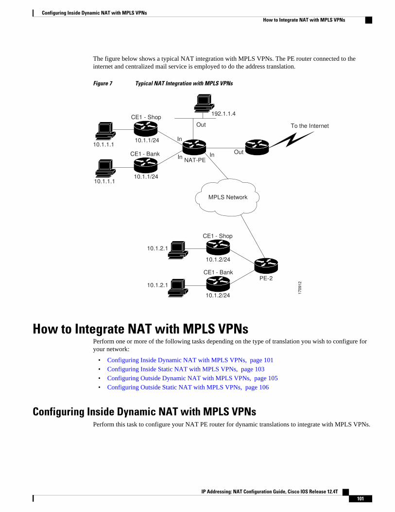
The figure below shows a typical NAT integration with MPLS VPNs. The PE router connected to theinternet and centralized mail service is employed to do the address translation.
Figure 7 Typical NAT Integration with MPLS VPNs
10.1.1/24 10.1.1.1
CE1 - Bank
10.1.1/24 10.1.1.1
To the Internet
192.1.1.4
CE1 - Shop
10.1.2/24
10.1.2.1
CE1 - Bank
10.1.2/24
10.1.2.1
Out
Out
In
MPLS Network
In
In
PE-2
170912
NAT-PE
CE1 - Shop
How to Integrate NAT with MPLS VPNsPerform one or more of the following tasks depending on the type of translation you wish to configure foryour network:
• Configuring Inside Dynamic NAT with MPLS VPNs, page 101
• Configuring Inside Static NAT with MPLS VPNs, page 103
• Configuring Outside Dynamic NAT with MPLS VPNs, page 105
• Configuring Outside Static NAT with MPLS VPNs, page 106
Configuring Inside Dynamic NAT with MPLS VPNsPerform this task to configure your NAT PE router for dynamic translations to integrate with MPLS VPNs.
Configuring Inside Dynamic NAT with MPLS VPNsHow to Integrate NAT with MPLS VPNs
IP Addressing: NAT Configuration Guide, Cisco IOS Release 12.4T 101

SUMMARY STEPS
1. enable
2. configure terminal
3. ip nat pool name start-ip end-ip netmask netmask
4. ip nat [inside | outside] source [list {access-list-number | access-list-name} | route-map name][interface type number | pool pool-name] vrf vrf-name[overload]
5. Repeat Step 4 for each VPN being configured
6. ip route vrf vrf-name prefix mask interface-type interface-number next-hop-address
7. Repeat Step 6 for each VPN being configured.
8. exit
9. show ip nat translations vrf vrf-name
DETAILED STEPS
Command or Action Purpose
Step 1 enable
Example:
Router> enable
Enables higher privilege levels, such asprivileged EXEC mode.
• Enter your password if prompted.
Step 2 configure terminal
Example:
Router# configure terminal
Enters global configuration mode.
Step 3 ip nat pool name start-ip end-ip netmask netmask
Example:
Router(config)# ip nat pool inside 2.2.2.10 2.2.2.10 netmask 255.255.255.0
Defines a pool of IP addresses for NAT.
Step 4 ip nat [inside | outside] source [list {access-list-number | access-list-name} |route-map name] [interface type number | pool pool-name] vrf vrf-name[overload]
Example:
Router(config)# ip nat inside source list 1 pool mypool vrf shop overload
Allows NAT to be configured on aparticular VPN.
Step 5 Repeat Step 4 for each VPN being configured --
Integrating NAT with MPLS VPNs How to Integrate NAT with MPLS VPNs
IP Addressing: NAT Configuration Guide, Cisco IOS Release 12.4T102

Command or Action Purpose
Step 6 ip route vrf vrf-name prefix mask interface-type interface-number next-hop-address
Example:
Router(config)# ip route vrf shop 0.0.0.0 0.0.0.0 ethernet 0 168.58.88.2
Allows NAT to be configured on aparticular VPN.
Step 7 Repeat Step 6 for each VPN being configured. --
Step 8 exit
Example:
Router(config)# exit
Returns to privileged EXEC mode.
Step 9 show ip nat translations vrf vrf-name
Example:
Router# show ip nat translations vrf shop
(Optional) Displays the settings used byvirtual routing/forwarding (VRF) tabletranslations.
Configuring Inside Static NAT with MPLS VPNsPerform this task to configure your NAT PE router for static translations to integrate with MPLS VPNs.
SUMMARY STEPS
1. enable
2. configure terminal
3. ip nat inside source {static {esp local-ip interface type number | local-ip global-ip}} [extendable |mapping-id map-id| no-alias | no-payload | redundancy group-name | route-map | vrf name]
4. Repeat Step 3 for each VPN being configured.
5. ip route vrf vrf-name prefix prefix mask next-hop-address global
6. Repeat Step 5 for each VPN being configured.
7. exit
8. show ip nat translations vrf vrf-name
Configuring Inside Static NAT with MPLS VPNsHow to Integrate NAT with MPLS VPNs
IP Addressing: NAT Configuration Guide, Cisco IOS Release 12.4T 103

DETAILED STEPS
Command or Action Purpose
Step 1 enable
Example:
Router> enable
Enables higher privilege levels, such asprivileged EXEC mode.
• Enter your password if prompted.
Step 2 configure terminal
Example:
Router# configure terminal
Enters global configuration mode.
Step 3 ip nat inside source {static {esp local-ip interface type number | local-ipglobal-ip}} [extendable | mapping-id map-id| no-alias | no-payload |redundancy group-name | route-map | vrf name]
Example:
Router(config)# ip nat inside source static 192.168.121.113 2.2.2.1 vrf shop
Enables inside static translation on theVRF.
Step 4 Repeat Step 3 for each VPN being configured. --
Step 5 ip route vrf vrf-name prefix prefix mask next-hop-address global
Example:
Router(config)# ip route vrf shop 0.0.0.0 0.0.0.0 168.58.88.2 global
Allows the route to be shared by severalcustomers.
Step 6 Repeat Step 5 for each VPN being configured. --
Step 7 exit
Example:
Router(config)# exit
Returns to privileged EXEC mode.
Step 8 show ip nat translations vrf vrf-name
Example:
Router# show ip nat translations vrf shop
(Optional) Displays the settings used byVRF translations.
Integrating NAT with MPLS VPNs How to Integrate NAT with MPLS VPNs
IP Addressing: NAT Configuration Guide, Cisco IOS Release 12.4T104

Configuring Outside Dynamic NAT with MPLS VPNsPerform this step to configure your NAT PE router for dynamic outside translations to integrate with MPLSVPNs.
SUMMARY STEPS
1. enable
2. configure terminal
3. ip nat pool outside global-ip local-ip netmask netmask
4. ip nat inside source static local-ip global-ip vrf vrf-name
5. Repeat Step 4 for each VRF being configured.
6. ip nat outside source static global-ip local-ip vrf vrf-name
7. exit
8. show ip nat translations vrf vrf-name
DETAILED STEPS
Command or Action Purpose
Step 1 enable
Example:
Router> enable
Enables higher privilege levels, such asprivileged EXEC mode.
• Enter your password if prompted.
Step 2 configure terminal
Example:
Router# configure terminal
Enters global configuration mode.
Step 3 ip nat pool outside global-ip local-ip netmask netmask
Example:
Router(config)# ip nat pool outside 4.4.4.1 4.4.4.254 netmask 255.255.255.00
Allows the configured VRF to be associatedwith the NAT translation rule.
Step 4 ip nat inside source static local-ip global-ip vrf vrf-name
Example:
Router(config)# ip nat inside source static 192.168.121.113 2.2.2.1 vrf shop
Allows the route to be shared by severalcustomers.
Step 5 Repeat Step 4 for each VRF being configured. Allows the route to be shared by severalcustomers.
Configuring Outside Dynamic NAT with MPLS VPNsHow to Integrate NAT with MPLS VPNs
IP Addressing: NAT Configuration Guide, Cisco IOS Release 12.4T 105
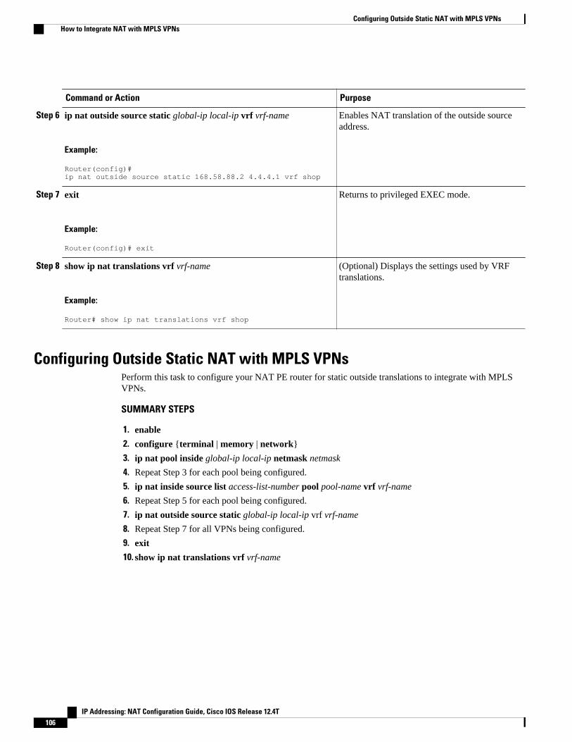
Command or Action Purpose
Step 6 ip nat outside source static global-ip local-ip vrf vrf-name
Example:
Router(config)# ip nat outside source static 168.58.88.2 4.4.4.1 vrf shop
Enables NAT translation of the outside sourceaddress.
Step 7 exit
Example:
Router(config)# exit
Returns to privileged EXEC mode.
Step 8 show ip nat translations vrf vrf-name
Example:
Router# show ip nat translations vrf shop
(Optional) Displays the settings used by VRFtranslations.
Configuring Outside Static NAT with MPLS VPNsPerform this task to configure your NAT PE router for static outside translations to integrate with MPLSVPNs.
SUMMARY STEPS
1. enable
2. configure {terminal | memory | network}
3. ip nat pool inside global-ip local-ip netmask netmask
4. Repeat Step 3 for each pool being configured.
5. ip nat inside source list access-list-number pool pool-name vrf vrf-name
6. Repeat Step 5 for each pool being configured.
7. ip nat outside source static global-ip local-ip vrf vrf-name
8. Repeat Step 7 for all VPNs being configured.
9. exit
10. show ip nat translations vrf vrf-name
Configuring Outside Static NAT with MPLS VPNs How to Integrate NAT with MPLS VPNs
IP Addressing: NAT Configuration Guide, Cisco IOS Release 12.4T106

DETAILED STEPS
Command or Action Purpose
Step 1 enable
Example:
Router> enable
Enables higher privilege levels, such asprivileged EXEC mode.
• Enter your password if prompted.
Step 2 configure {terminal | memory | network}
Example:
Router# configure terminal
Enters global configuration mode.
Step 3 ip nat pool inside global-ip local-ip netmask netmask
Example:
Router(config)# ip nat pool inside1 2.2.1.1 2.2.1.254 netmask 255.255.255.0
Allows the configured VRF to beassociated with the NAT translation rule.
Step 4 Repeat Step 3 for each pool being configured. --
Step 5 ip nat inside source list access-list-number pool pool-name vrf vrf-name
Example:
Router(config)# ip nat inside source list 1 pool inside2 vrf shop
Allows the route to be shared by severalcustomers.
Step 6 Repeat Step 5 for each pool being configured. Defines the access list.
Step 7 ip nat outside source static global-ip local-ip vrf vrf-name
Example:
Router(config)# ip nat outside source static 168.58.88.2 4.4.4.1 vrf shop
Allows the route to be shared by severalcustomers.
Step 8 Repeat Step 7 for all VPNs being configured. --
Step 9 exit
Example:
Router(config)# exit
Returns to privileged EXEC mode.
Integrating NAT with MPLS VPNsHow to Integrate NAT with MPLS VPNs
IP Addressing: NAT Configuration Guide, Cisco IOS Release 12.4T 107
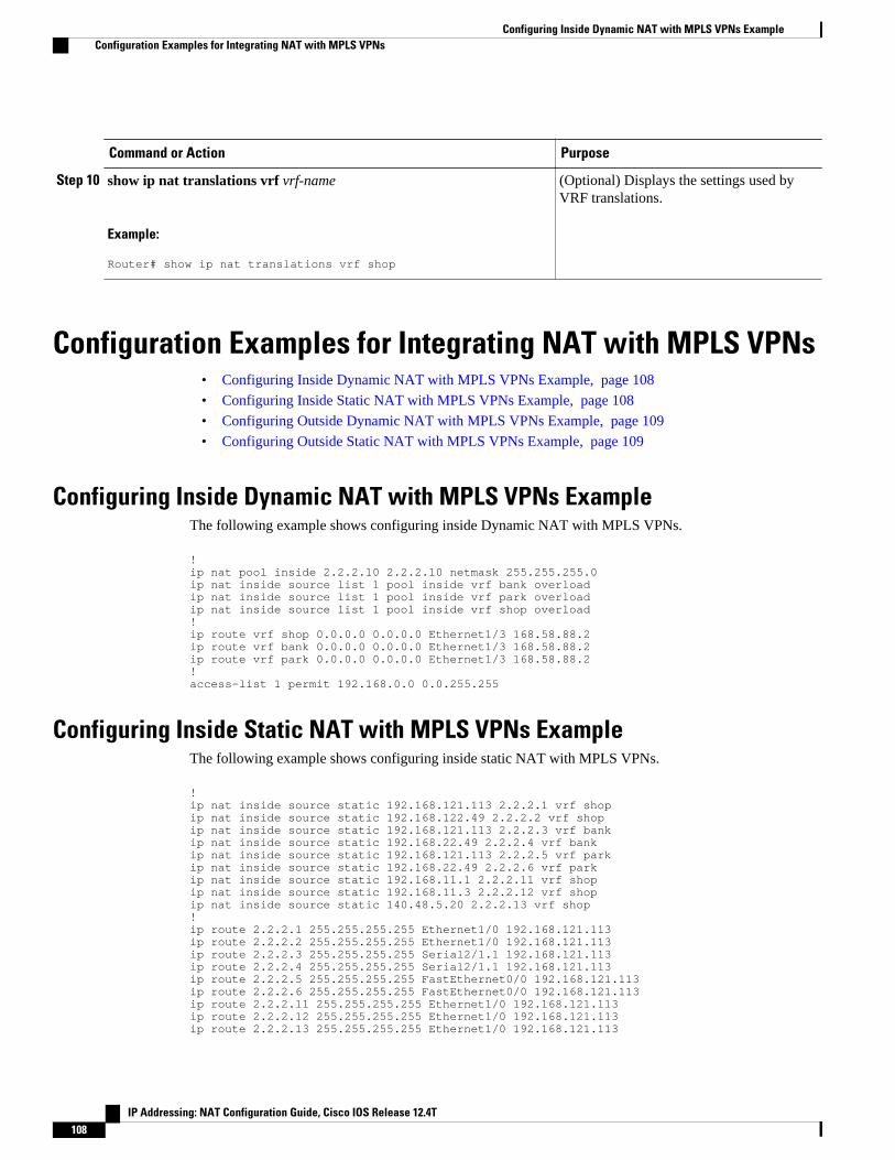
Command or Action Purpose
Step 10 show ip nat translations vrf vrf-name
Example:
Router# show ip nat translations vrf shop
(Optional) Displays the settings used byVRF translations.
Configuration Examples for Integrating NAT with MPLS VPNs• Configuring Inside Dynamic NAT with MPLS VPNs Example, page 108
• Configuring Inside Static NAT with MPLS VPNs Example, page 108
• Configuring Outside Dynamic NAT with MPLS VPNs Example, page 109
• Configuring Outside Static NAT with MPLS VPNs Example, page 109
Configuring Inside Dynamic NAT with MPLS VPNs ExampleThe following example shows configuring inside Dynamic NAT with MPLS VPNs.
!ip nat pool inside 2.2.2.10 2.2.2.10 netmask 255.255.255.0ip nat inside source list 1 pool inside vrf bank overloadip nat inside source list 1 pool inside vrf park overloadip nat inside source list 1 pool inside vrf shop overload!ip route vrf shop 0.0.0.0 0.0.0.0 Ethernet1/3 168.58.88.2ip route vrf bank 0.0.0.0 0.0.0.0 Ethernet1/3 168.58.88.2ip route vrf park 0.0.0.0 0.0.0.0 Ethernet1/3 168.58.88.2!access-list 1 permit 192.168.0.0 0.0.255.255
Configuring Inside Static NAT with MPLS VPNs ExampleThe following example shows configuring inside static NAT with MPLS VPNs.
!ip nat inside source static 192.168.121.113 2.2.2.1 vrf shopip nat inside source static 192.168.122.49 2.2.2.2 vrf shopip nat inside source static 192.168.121.113 2.2.2.3 vrf bankip nat inside source static 192.168.22.49 2.2.2.4 vrf bankip nat inside source static 192.168.121.113 2.2.2.5 vrf parkip nat inside source static 192.168.22.49 2.2.2.6 vrf parkip nat inside source static 192.168.11.1 2.2.2.11 vrf shopip nat inside source static 192.168.11.3 2.2.2.12 vrf shopip nat inside source static 140.48.5.20 2.2.2.13 vrf shop!ip route 2.2.2.1 255.255.255.255 Ethernet1/0 192.168.121.113ip route 2.2.2.2 255.255.255.255 Ethernet1/0 192.168.121.113ip route 2.2.2.3 255.255.255.255 Serial2/1.1 192.168.121.113ip route 2.2.2.4 255.255.255.255 Serial2/1.1 192.168.121.113ip route 2.2.2.5 255.255.255.255 FastEthernet0/0 192.168.121.113ip route 2.2.2.6 255.255.255.255 FastEthernet0/0 192.168.121.113ip route 2.2.2.11 255.255.255.255 Ethernet1/0 192.168.121.113ip route 2.2.2.12 255.255.255.255 Ethernet1/0 192.168.121.113ip route 2.2.2.13 255.255.255.255 Ethernet1/0 192.168.121.113
Configuring Inside Dynamic NAT with MPLS VPNs Example Configuration Examples for Integrating NAT with MPLS VPNs
IP Addressing: NAT Configuration Guide, Cisco IOS Release 12.4T108

Configuring Outside Dynamic NAT with MPLS VPNs ExampleThe following example shows configuring outside dynamic NAT with MPLS VPNs.
!ip nat pool outside 4.4.4.1 4.4.4.254 netmask 255.255.255.0ip nat inside source static 192.168.121.113 2.2.2.1 vrf shopip nat inside source static 192.168.122.49 2.2.2.2 vrf shopip nat inside source static 192.168.121.113 2.2.2.3 vrf bankip nat inside source static 192.168.22.49 2.2.2.4 vrf bankip nat inside source static 192.168.121.113 2.2.2.5 vrf parkip nat inside source static 192.168.22.49 2.2.2.6 vrf parkip nat outside source list 1 pool outside!
Configuring Outside Static NAT with MPLS VPNs ExampleThe following example shows configuring outside static NAT with MPLS VPNs.
!ip default-gateway 10.1.15.1ip nat pool inside1 2.2.1.1 2.2.1.254 netmask 255.255.255.0ip nat pool inside2 2.2.2.1 2.2.2.254 netmask 255.255.255.0ip nat pool inside3 2.2.3.1 2.2.3.254 netmask 255.255.255.0ip nat inside source list 1 pool inside2 vrf bankip nat inside source list 1 pool inside3 vrf parkip nat inside source list 1 pool inside1 vrf shopip nat outside source static 168.58.88.2 4.4.4.1 vrf bankip nat outside source static 18.68.58.1 4.4.4.2 vrf parkip nat outside source static 168.58.88.1 4.4.4.3 vrf shopip classlessip route 192.170.10.0 255.255.255.0 Ethernet1/0 192.168.121.113ip route 192.170.11.0 255.255.255.0 Serial2/1.1 192.168.121.113ip route 192.170.12.0 255.255.255.0 FastEthernet0/0 192.168.121.113ip route vrf shop 0.0.0.0 0.0.0.0 168.58.88.2 globalip route vrf bank 0.0.0.0 0.0.0.0 168.58.88.2 globalip route vrf park 0.0.0.0 0.0.0.0 168.58.88.2 globalno ip http server!access-list 1 permit 192.168.0.0 0.0.255.255
Where to Go Next• To learn about Network Address Translation and configure NAT for IP address conservation, see the
“Configuring NAT for IP Address Conservation” module.• To verify, monitor, and maintain NAT, see the “Monitoring and Maintaining NAT” module.• To use NAT with application level gateways, see the “Using Application Level Gateways with NAT”
module.• To configure NAT for high availability, see the “Configuring NAT for High Availability” module.
Additional References
Configuring Outside Dynamic NAT with MPLS VPNs ExampleWhere to Go Next
IP Addressing: NAT Configuration Guide, Cisco IOS Release 12.4T 109

Related Documents
Related Topic Document Title
NAT commands: complete command syntax,command mode, command history, defaults, usageguidelines and examples
Cisco IOS IP Addressing Services CommandReference
NAT high availability “Configuring NAT for High Availability” module
Application Level Gateways “Using Application Level Gateways with NAT”
Maintain and monitor NAT “Monitoring and Maintaining NAT” module
IP Address Conservation “Configuring NAT for IP Address Conservation”module
Standards
Standards Title
None --
MIBs
MIBs MIBs Link
• None To locate and download MIBs for selectedplatforms, Cisco IOS releases, and feature sets, useCisco MIB Locator found at the following URL:
http://www.cisco.com/go/mibs
RFCs
RFCs1 Title
RFC 2547 BGP/MPLS VPNs
1 Not all supported RFCs are listed.
Integrating NAT with MPLS VPNs Additional References
IP Addressing: NAT Configuration Guide, Cisco IOS Release 12.4T110

Technical Assistance
Description Link
The Cisco Support and Documentation websiteprovides online resources to downloaddocumentation, software, and tools. Use theseresources to install and configure the software andto troubleshoot and resolve technical issues withCisco products and technologies. Access to mosttools on the Cisco Support and Documentationwebsite requires a Cisco.com user ID andpassword.
http://www.cisco.com/cisco/web/support/index.html
Feature Information for Integrating NAT with MPLS VPNsThe following table provides release information about the feature or features described in this module.This table lists only the software release that introduced support for a given feature in a given softwarerelease train. Unless noted otherwise, subsequent releases of that software release train also support thatfeature.
Use Cisco Feature Navigator to find information about platform support and Cisco software image support.To access Cisco Feature Navigator, go to www.cisco.com/go/cfn. An account on Cisco.com is not required.
Table 5 Feature Information for Integrating NAT with MPLS VPNs
Feature Name Releases Feature Configuration Information
Network Address Translation(NAT) Integration with MPLSVPNs feature
12.1(13)T This feature allows multipleMultiprotocol Label Switching(MPLS) Virtual Private Networks(VPNs) to be configured on asingle device to work together.
Cisco and the Cisco logo are trademarks or registered trademarks of Cisco and/or its affiliates in the U.S.and other countries. To view a list of Cisco trademarks, go to this URL: www.cisco.com/go/trademarks.Third-party trademarks mentioned are the property of their respective owners. The use of the word partnerdoes not imply a partnership relationship between Cisco and any other company. (1110R)
Any Internet Protocol (IP) addresses and phone numbers used in this document are not intended to beactual addresses and phone numbers. Any examples, command display output, network topology diagrams,and other figures included in the document are shown for illustrative purposes only. Any use of actual IPaddresses or phone numbers in illustrative content is unintentional and coincidental.
Integrating NAT with MPLS VPNsFeature Information for Integrating NAT with MPLS VPNs
IP Addressing: NAT Configuration Guide, Cisco IOS Release 12.4T 111

Configuring Outside Static NAT with MPLS VPNs Example
IP Addressing: NAT Configuration Guide, Cisco IOS Release 12.4T112
Configuring Hosted NAT Traversal for SessionBorder Controller
The Cisco IOS Hosted NAT Traversal for Session Border Controller Phase-1 feature enables a Cisco IOSNetwork Address Translation (NAT) Session Initiation Protocol (SIP) Application Level Gateway (ALG)router to act as a Session Border Controller (SBC) on a Cisco Multiservice IP-to-IP gateway, ensuring aseamless delivery of VoIP services.
The Cisco IOS Hosted NAT Traversal for Session Border Controller Phase-2 feature provides registrationthrottling, media flow-through, and Stateful NAT (SNAT) support.
• Finding Feature Information, page 113• Prerequisites for Configuring Cisco IOS Hosted NAT Traversal for Session Border Controller, page
114• Restrictions for Configuring Cisco IOS Hosted NAT Traversal for Session Border Controller, page
114• Information About Configuring Cisco IOS Hosted NAT Traversal for Session Border Controller,
page 114• How to Configure Cisco IOS Hosted NAT for Session Border Controller, page 116• Configuration Examples for Configuring Cisco IOS Hosted NAT for Session Border Controller, page
121• Additional References, page 122• Feature Information for Configuring Hosted NAT Traversal for Session Border Controller, page
123
Finding Feature InformationYour software release may not support all the features documented in this module. For the latest featureinformation and caveats, see the release notes for your platform and software release. To find informationabout the features documented in this module, and to see a list of the releases in which each feature issupported, see the Feature Information Table at the end of this document.
Use Cisco Feature Navigator to find information about platform support and Cisco software image support.To access Cisco Feature Navigator, go to www.cisco.com/go/cfn. An account on Cisco.com is not required.
IP Addressing: NAT Configuration Guide, Cisco IOS Release 12.4T 113

Prerequisites for Configuring Cisco IOS Hosted NAT Traversalfor Session Border Controller
• Before you configure the Cisco IOS Hosted NAT Traversal for Session Border Controller feature, youshould understand the concepts documented in “Cisco IOS Hosted NAT Traversal for Session BorderController Overview” section.
• All access lists required for use with the tasks in this module should be configured prior to beginningthe configuration task. For information about how to configure an access list, see the “Creating an IPAccess List and Applying It to an Interface” module in the Securing the Data Plane ConfigurationGuide.
• Before performing the tasks in this module, you should verify that SIP has not been disabled. SIP isenabled by default.
Restrictions for Configuring Cisco IOS Hosted NAT Traversalfor Session Border Controller
• Phase 1 supports flow-around mode for inside to inside media calls and flow-through for inside tooutside media calls.
• If the intermediate routers between the inside phones and the NAT SBC are configured for PortAddress Translation (PAT), the user agents (phones and proxy) must support symmetric signaling andsymmetric and early media. The override port must be configured on the NAT SBC router. In theabsence of support for symmetric signaling and symmetric and early media, the intermediate routersmust be configured for non-PAT and the override address should be configured in the NAT SBC.
Information About Configuring Cisco IOS Hosted NATTraversal for Session Border Controller
• Voice and Multimedia over IP Networks, page 114
• Cisco IOS Hosted NAT Traversal for Session Border Controller Overview, page 115
Voice and Multimedia over IP NetworksSIP is a protocol developed by the IETF Multiparty Multimedia Session Control (MMUSIC) WorkingGroup. The Cisco SIP functionality equips Cisco routers to signal the setup of voice and multimedia callsover IP networks. SIP provides an alternative to the H.323 protocol within the VoIP internetworkingsoftware.
Session Description Protocol (SDP) describes multimedia sessions. SDP may be used in SIP messagebodies to describe the multimedia sessions that are used for creating and controlling the multimediasessions with two or more participants.
Voice and Multimedia over IP Networks Prerequisites for Configuring Cisco IOS Hosted NAT Traversal for Session Border Controller
IP Addressing: NAT Configuration Guide, Cisco IOS Release 12.4T114

Cisco IOS Hosted NAT Traversal for Session Border Controller OverviewPrivate IP addresses and ports inserted in the packet payload by client devices, such as IP phones and videoconferencing stations, are not routable in public networks using NAT. In addition, intermediate routersbetween the inside phones and the NAT SBC can have the non-ALG functionality. The hosted NATtraversal handles the signaling and the media streams involved in the setting up, conducting, and tearingdown of calls that traverse these intermediate routers.
The figure below illustrates how the NAT SBC handles embedded SIP/SDP information for the address andport allocation by differentiating the overlapped embedded information.
Figure 8 NAT as a SIP Session Border Controller
IP
IP
VRF-A
AS5XX
192.0.2.2
Softswitch
200.1.1.1
BTS orCSPS
SIP Phone A10.1.1.1
17
02
68
IP
VRF-B
SIP Phone B10.2.2.2
Access Router A(may be non-
ALG NAT)NAT-Pool: 172.16.1.1
Access Router B(may be non-
ALG NAT)NAT-Pool: 172.16.2.1
EdgeRouteEdgeRoute
NAT SBC
The inside phones have the proxy configured as the NAT SBC’s preconfigured address and port. NAT SBChas the Softswitch’s address and port preconfigured as the proxy. The NAT SBC intercepts the packetsdestined from the inside phones to itself and translates the inside hosts and other information in theSIP/SDP payload and the IP/UDP destination address or port to the Softswitch’s address and port, and viceversa.
SIP/SDP information is either a NAT or a PAT in order for the Real-Time Transport Protocol (RTP) flowto be directly between the phones in the NAT SBC inside domain.
The address-only fields are not translated by the NAT SIP ALG. The address-only fields are handled by theNAT SBC, except for the proxy-authorization and authorization translation, because these will break theauthentication.
If the intermediate routers between the inside phones and the NAT SBC are configured to do a PAT, theuser agents (phones and proxy) must support symmetric signaling and symmetric and early media. Youmust configure the override port on the NAT SBC router. In the absence of support for symmetric signalingand symmetric and early media, the intermediate routers must be configured without PAT and the overrideaddress should be configured in the NAT SBC.
The registration throttling support enables you to define the parameters in the Expires: header and theexpires= parameter. It allows you to elect to not forward certain registration messages to the Softswitch.
Cisco IOS Hosted NAT Traversal for Session Border Controller OverviewInformation About Configuring Cisco IOS Hosted NAT Traversal for Session Border Controller
IP Addressing: NAT Configuration Guide, Cisco IOS Release 12.4T 115
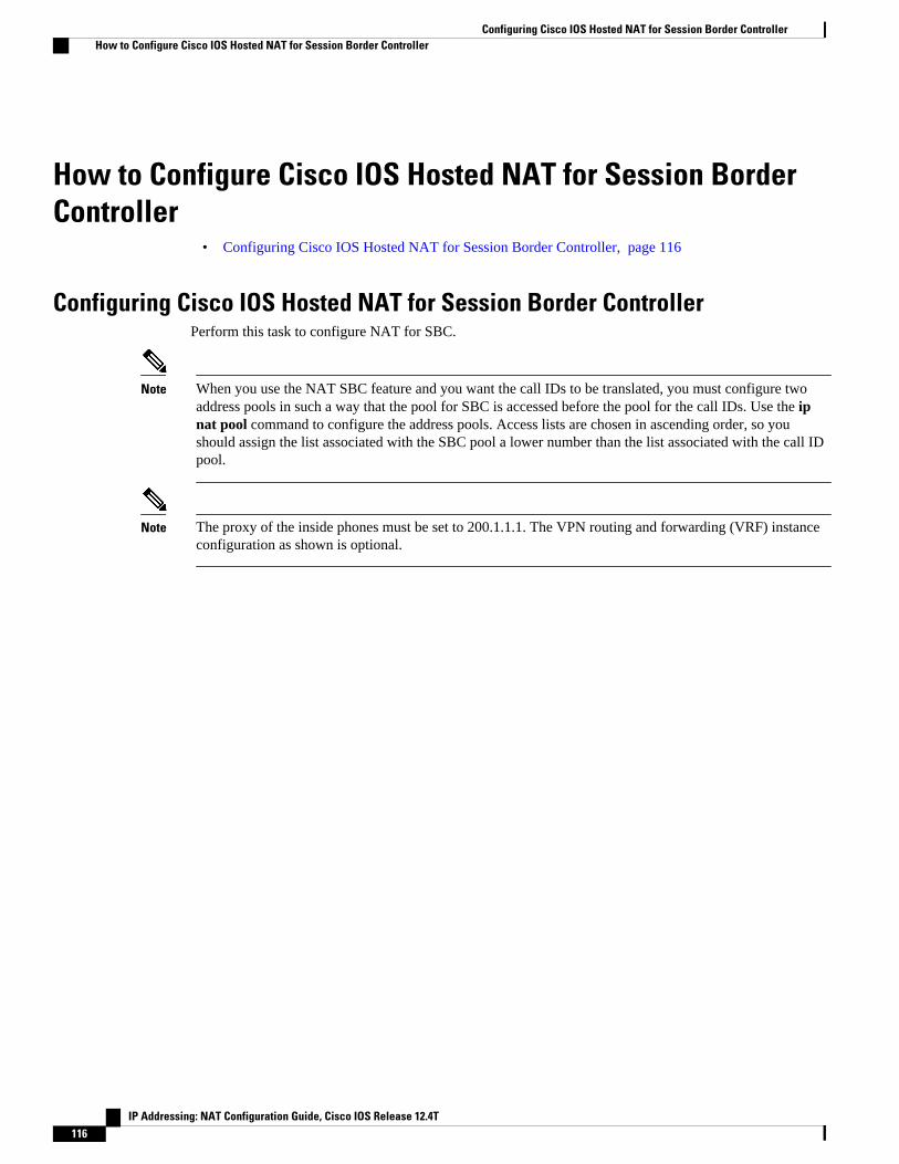
How to Configure Cisco IOS Hosted NAT for Session BorderController
• Configuring Cisco IOS Hosted NAT for Session Border Controller, page 116
Configuring Cisco IOS Hosted NAT for Session Border ControllerPerform this task to configure NAT for SBC.
Note When you use the NAT SBC feature and you want the call IDs to be translated, you must configure twoaddress pools in such a way that the pool for SBC is accessed before the pool for the call IDs. Use the ipnat pool command to configure the address pools. Access lists are chosen in ascending order, so youshould assign the list associated with the SBC pool a lower number than the list associated with the call IDpool.
Note The proxy of the inside phones must be set to 200.1.1.1. The VPN routing and forwarding (VRF) instanceconfiguration as shown is optional.
Configuring Cisco IOS Hosted NAT for Session Border Controller How to Configure Cisco IOS Hosted NAT for Session Border Controller
IP Addressing: NAT Configuration Guide, Cisco IOS Release 12.4T116

SUMMARY STEPS
1. enable
2. configure terminal
3. interface type number
4. ip nat inside
5. exit
6. interface type number
7. ip nat outside
8. exit
9. ip nat pool name start-ip end-ip {netmask netmask | prefix-length prefix-length}
10. ip nat pool name start-ip end-ip {netmask netmask | prefix-length prefix-length}
11. ip nat inside source list access-list-number pool name [vrf vrf-name] [overload]
12. ip nat outside source list access-list-number pool name
13. ip nat sip-sbc
14. proxy inside-address inside-port outside-address outside-port protocol udp
15. vrf-list
16. vrf-name vrf - name
17. exit
18. ip nat sip-sbc
19. call-id-pool call -id-pool
20. session -timeout seconds
21. mode allow -flow-around
22. override address
23. end
DETAILED STEPS
Command or Action Purpose
Step 1 enable
Example:
Router> enable
Enables privileged EXEC mode.
• Enter your password if prompted.
Step 2 configure terminal
Example:
Router# configure terminal
Enters global configuration mode.
Configuring Hosted NAT Traversal for Session Border ControllerHow to Configure Cisco IOS Hosted NAT for Session Border Controller
IP Addressing: NAT Configuration Guide, Cisco IOS Release 12.4T 117

Command or Action Purpose
Step 3 interface type number
Example:
Router(config)# interface ethernet 1/1
Specifies an interface and returns to interface configurationmode.
Step 4 ip nat inside
Example:
Router(config-if)# ip nat inside
Connects the interface to the inside network (the networksubject to NAT translation).
Step 5 exit
Example:
Router(config-if)# exit
Exits interface configuration mode and enters globalconfiguration mode.
Step 6 interface type number
Example:
Router(config)# interface ethernet 1/3
Specifies an interface and enters interface configuration mode.
Step 7 ip nat outside
Example:
Router(config-if)# ip nat outside
Connects the interface to the outside network.
Step 8 exit
Example:
Router(config-if)# exit
Exits interface configuration mode and returns to globalconfiguration mode.
Step 9 ip nat pool name start-ip end-ip {netmask netmask |prefix-length prefix-length}
Example:
Router(config)# ip nat pool inside-pool-A 172.16.0.1 172.16.0.10 prefix-length 16
Defines a pool of global addresses to be allocated for the insidenetwork.
Note You must configure two address pools when you areusing the NAT SBC feature and you want to translate thecall IDs. In this step you are configuring the first addresspool.
Configuring Hosted NAT Traversal for Session Border Controller How to Configure Cisco IOS Hosted NAT for Session Border Controller
IP Addressing: NAT Configuration Guide, Cisco IOS Release 12.4T118
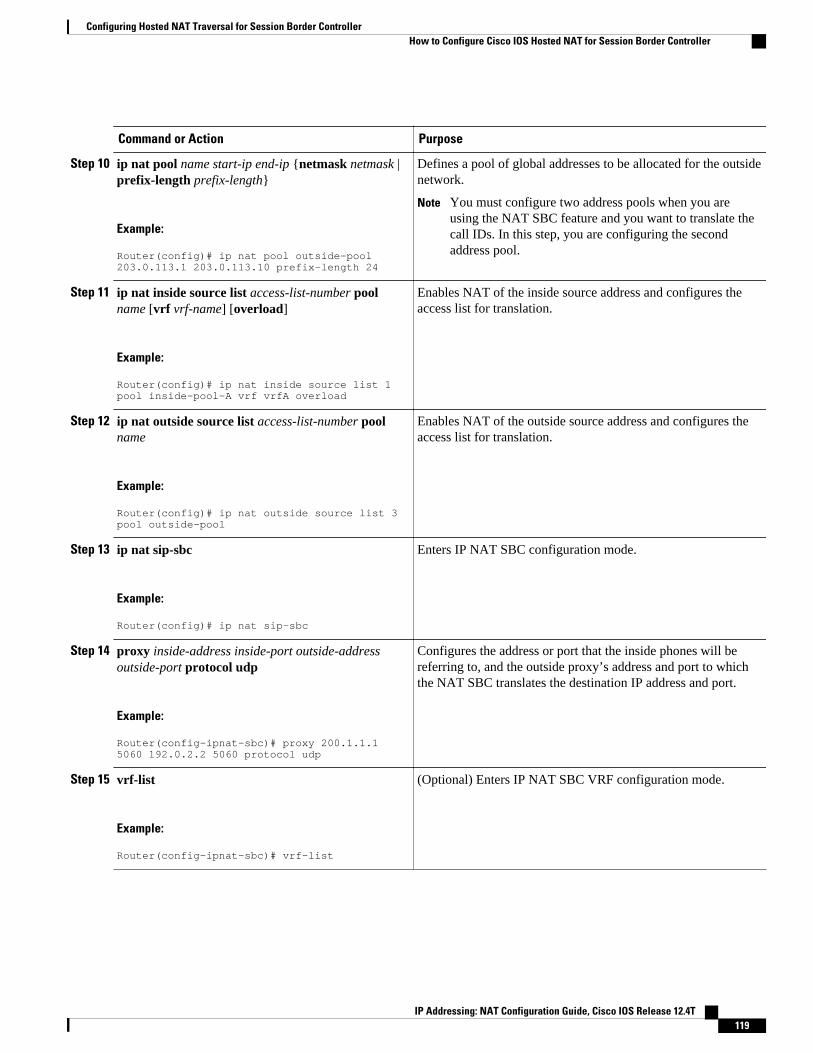
Command or Action Purpose
Step 10 ip nat pool name start-ip end-ip {netmask netmask |prefix-length prefix-length}
Example:
Router(config)# ip nat pool outside-pool 203.0.113.1 203.0.113.10 prefix-length 24
Defines a pool of global addresses to be allocated for the outsidenetwork.
Note You must configure two address pools when you areusing the NAT SBC feature and you want to translate thecall IDs. In this step, you are configuring the secondaddress pool.
Step 11 ip nat inside source list access-list-number poolname [vrf vrf-name] [overload]
Example:
Router(config)# ip nat inside source list 1 pool inside-pool-A vrf vrfA overload
Enables NAT of the inside source address and configures theaccess list for translation.
Step 12 ip nat outside source list access-list-number poolname
Example:
Router(config)# ip nat outside source list 3 pool outside-pool
Enables NAT of the outside source address and configures theaccess list for translation.
Step 13 ip nat sip-sbc
Example:
Router(config)# ip nat sip-sbc
Enters IP NAT SBC configuration mode.
Step 14 proxy inside-address inside-port outside-addressoutside-port protocol udp
Example:
Router(config-ipnat-sbc)# proxy 200.1.1.1 5060 192.0.2.2 5060 protocol udp
Configures the address or port that the inside phones will bereferring to, and the outside proxy’s address and port to whichthe NAT SBC translates the destination IP address and port.
Step 15 vrf-list
Example:
Router(config-ipnat-sbc)# vrf-list
(Optional) Enters IP NAT SBC VRF configuration mode.
Configuring Hosted NAT Traversal for Session Border ControllerHow to Configure Cisco IOS Hosted NAT for Session Border Controller
IP Addressing: NAT Configuration Guide, Cisco IOS Release 12.4T 119
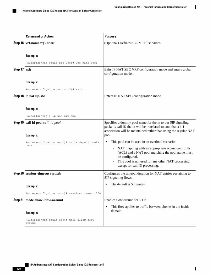
Command or Action Purpose
Step 16 vrf-name vrf - name
Example:
Router(config-ipnat-sbc-vrf)# vrf-name vrf1
(Optional) Defines SBC VRF list names.
Step 17 exit
Example:
Router(config-ipnat-sbc-vrf)# exit
Exits IP NAT SBC VRF configuration mode and enters globalconfiguration mode.
Step 18 ip nat sip-sbc
Example:
Router(config)# ip nat sip-sbc
Enters IP NAT SBC configuration mode.
Step 19 call-id-pool call -id-pool
Example:
Router(config-ipnat-sbc)# call-id-pool pool-name
Specifies a dummy pool name for the in to out SIP signalingpacket’s call ID that it will be translated to, and that a 1:1association will be maintained rather than using the regular NATpool.
• This pool can be used in an overload scenario:
◦ NAT mapping with an appropriate access control list(ACL) and a NAT pool matching the pool name mustbe configured.
◦ This pool is not used for any other NAT processingexcept for call ID processing.
Step 20 session -timeout seconds
Example:
Router(config-ipnat-sbc)# session-timeout 300
Configures the timeout duration for NAT entries pertaining toSIP signaling flows.
• The default is 5 minutes.
Step 21 mode allow -flow-around
Example:
Router(config-ipnat-sbc)# mode allow-flow-around
Enables flow-around for RTP.
• This flow applies to traffic between phones in the insidedomain.
Configuring Hosted NAT Traversal for Session Border Controller How to Configure Cisco IOS Hosted NAT for Session Border Controller
IP Addressing: NAT Configuration Guide, Cisco IOS Release 12.4T120
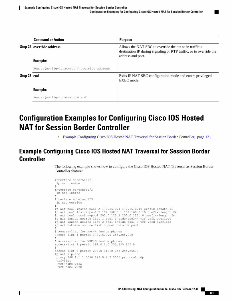
Command or Action Purpose
Step 22 override address
Example:
Router(config-ipnat-sbc)# override address
Allows the NAT SBC to override the out to in traffic’sdestination IP during signaling or RTP traffic, or to override theaddress and port.
Step 23 end
Example:
Router(config-ipnat-sbc)# end
Exits IP NAT SBC configuration mode and enters privilegedEXEC mode.
Configuration Examples for Configuring Cisco IOS HostedNAT for Session Border Controller
• Example Configuring Cisco IOS Hosted NAT Traversal for Session Border Controller, page 121
Example Configuring Cisco IOS Hosted NAT Traversal for Session BorderController
The following example shows how to configure the Cisco IOS Hosted NAT Traversal as Session BorderController feature:
interface ethernet1/1 ip nat inside!interface ethernet1/2 ip nat inside!interface ethernet1/3 ip nat outside!ip nat pool inside-pool-A 172.16.0.1 172.16.0.10 prefix-length 16ip nat pool inside-pool-B 192.168.0.1 192.168.0.10 prefix-length 24ip nat pool outside-pool 203.0.113.1 203.0.113.10 prefix-length 24ip nat inside source list 1 pool inside-pool-A vrf vrfA overloadip nat inside source list 2 pool inside-pool-B vrf vrfB overloadip nat outside source list 3 pool outside-pool!! Access-list for VRF-A inside phonesaccess-list 1 permit 172.16.0.0 255.255.0.0!! Access-list for VRF-B inside phonesaccess-list 2 permit 192.0.2.0 255.255.255.0!access-list 3 permit 203.0.113.0 255.255.255.0ip nat sip-sbc proxy 200.1.1.1 5060 192.0.2.2 5060 protocol udp vrf-list vrf-name vrfA vrf-name vrfB
Example Configuring Cisco IOS Hosted NAT Traversal for Session Border ControllerConfiguration Examples for Configuring Cisco IOS Hosted NAT for Session Border Controller
IP Addressing: NAT Configuration Guide, Cisco IOS Release 12.4T 121

exit call-id-pool pool-name session-timeout 300 mode allow-flow-around override address
Additional ReferencesRelated Documents
Related Topic Document Title
Cisco IOS commands Cisco IOS Master Commands List, All Releases
NAT commands: complete command syntax,command mode, command history, defaults, usageguidelines, and examples
Cisco IOS IP Addressing Services CommandReference
Configuring an IP access list “Creating an IP Access List and Applying It to anInterface” module in the Securing the Data PlaneConfiguration Guide
Standards
Standards Title
None --
MIBs
MIBs MIBs Link
None To locate and download MIBs for selectedplatforms, Cisco IOS releases, and feature sets, useCisco MIB Locator found at the following URL:
http://www.cisco.com/go/mibs
Technical Assistance
Description Link
The Cisco Support and Documentation websiteprovides online resources to downloaddocumentation, software, and tools. Use theseresources to install and configure the software andto troubleshoot and resolve technical issues withCisco products and technologies. Access to mosttools on the Cisco Support and Documentationwebsite requires a Cisco.com user ID andpassword.
http://www.cisco.com/cisco/web/support/index.html
Configuring Hosted NAT Traversal for Session Border Controller Additional References
IP Addressing: NAT Configuration Guide, Cisco IOS Release 12.4T122
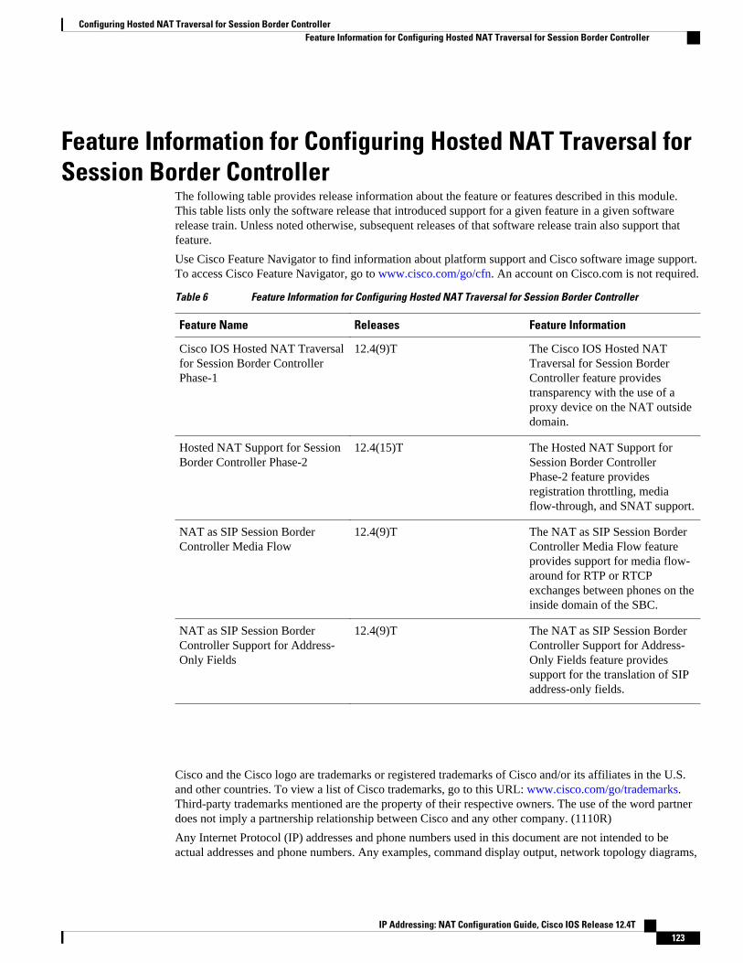
Feature Information for Configuring Hosted NAT Traversal forSession Border Controller
The following table provides release information about the feature or features described in this module.This table lists only the software release that introduced support for a given feature in a given softwarerelease train. Unless noted otherwise, subsequent releases of that software release train also support thatfeature.
Use Cisco Feature Navigator to find information about platform support and Cisco software image support.To access Cisco Feature Navigator, go to www.cisco.com/go/cfn. An account on Cisco.com is not required.
Table 6 Feature Information for Configuring Hosted NAT Traversal for Session Border Controller
Feature Name Releases Feature Information
Cisco IOS Hosted NAT Traversalfor Session Border ControllerPhase-1
12.4(9)T The Cisco IOS Hosted NATTraversal for Session BorderController feature providestransparency with the use of aproxy device on the NAT outsidedomain.
Hosted NAT Support for SessionBorder Controller Phase-2
12.4(15)T The Hosted NAT Support forSession Border ControllerPhase-2 feature providesregistration throttling, mediaflow-through, and SNAT support.
NAT as SIP Session BorderController Media Flow
12.4(9)T The NAT as SIP Session BorderController Media Flow featureprovides support for media flow-around for RTP or RTCPexchanges between phones on theinside domain of the SBC.
NAT as SIP Session BorderController Support for Address-Only Fields
12.4(9)T The NAT as SIP Session BorderController Support for Address-Only Fields feature providessupport for the translation of SIPaddress-only fields.
Cisco and the Cisco logo are trademarks or registered trademarks of Cisco and/or its affiliates in the U.S.and other countries. To view a list of Cisco trademarks, go to this URL: www.cisco.com/go/trademarks.Third-party trademarks mentioned are the property of their respective owners. The use of the word partnerdoes not imply a partnership relationship between Cisco and any other company. (1110R)
Any Internet Protocol (IP) addresses and phone numbers used in this document are not intended to beactual addresses and phone numbers. Any examples, command display output, network topology diagrams,
Configuring Hosted NAT Traversal for Session Border ControllerFeature Information for Configuring Hosted NAT Traversal for Session Border Controller
IP Addressing: NAT Configuration Guide, Cisco IOS Release 12.4T 123

and other figures included in the document are shown for illustrative purposes only. Any use of actual IPaddresses or phone numbers in illustrative content is unintentional and coincidental.
Configuring Hosted NAT Traversal for Session Border Controller
IP Addressing: NAT Configuration Guide, Cisco IOS Release 12.4T124
User Defined Source Port Ranges for PAT
The User Defined Source Port Ranges for PAT feature enables the specification of source port ranges forPort Address Translation (PAT) for SIP, H.323, and Skinny Real-Time Transport Protocol (RTP) andRTP Control Protocol (RTCP).
• Finding Feature Information, page 125• Restrictions for User Defined Source Port Ranges for PAT, page 125• Information About User Defined Source Port Ranges for PAT, page 125• How to Configure User Defined Source Port Ranges for PAT, page 126• Configuration Examples for User Defined Source Port Ranges for PAT, page 128• Additional References, page 129• Feature Information for User Defined Source Port Ranges for PAT, page 130
Finding Feature InformationYour software release may not support all the features documented in this module. For the latest featureinformation and caveats, see the release notes for your platform and software release. To find informationabout the features documented in this module, and to see a list of the releases in which each feature issupported, see the Feature Information Table at the end of this document.
Use Cisco Feature Navigator to find information about platform support and Cisco software image support.To access Cisco Feature Navigator, go to www.cisco.com/go/cfn. An account on Cisco.com is not required.
Restrictions for User Defined Source Port Ranges for PAT• The size of port range that can be reserved is limited to a multiple of 64.• The start port for the port range should also be a multiple of 64.
Information About User Defined Source Port Ranges for PAT• User Defined Source Port Ranges for PAT Overview, page 126
• Even Port Parity, page 126
IP Addressing: NAT Configuration Guide, Cisco IOS Release 12.4T 125

User Defined Source Port Ranges for PAT OverviewIn order for VoIP traffic to not be in violation of the RTP standards and best practices, even/odd pairing ofports for RTP and RTCP traffic for SIP ALG, Skinny and H.323 has been made available.
Following is a scenario of what happens to VoIP traffic translated using PAT without user defined ports.
The first VoIP traffic getting translated using PAT, would request for port 16384 and would get to use port16384 for its RTP traffic.
The second VoIP traffic stream getting translated using PAT would also request 16384 for its RTP. Sincethis port number is already in use by the first call, PAT would translate the 16384 source port for thesecond phone to 1024 (assuming the port was free) and this would be in violation of the RTP standards/bestpractices.
A third call would end up using port 1025 and others would increment from there.
Each call after the first call would end up having its inside source port translated to an external portassignment that is out of specifications for RTP, and this would continue until PAT binding fir the first callexpires.
Problems associated with RTP traffic being assigned to a non-standard port by PAT:
• Inability for compressed RTP (cRTP) to be invoked in the return direction, as it only operates on RTPflows with compliant port numbers.
• Difficulty in properly classifying voice traffic for corresponding QoS treatment.• Violation of standard firewall policies that specifically account for RTP/TRCP traffic by specified
standard port range.
Even Port ParityCisco IOS NAT SIP gateways normally select the next available port+1 for SIP fixup in the NATtranslations. The NAT gateway does not check for even/odd pair for RTP/TRCP port numbers, and as aresult issues may arise with SIP user agents that are strictly following the encouraged even/odd parity forRTP/RTCP port numbers.
Even port parity for SIP, H.323, and skinny is supported by default and it can be turned off forcing the oddRTP ports allocation.
How to Configure User Defined Source Port Ranges for PAT• Configuring Source Port Ranges for PAT, page 126
• Configuring Even Port Parity, page 127
Configuring Source Port Ranges for PATPerform this task to assign a set of ports and associate a map to them.
User Defined Source Port Ranges for PAT Overview How to Configure User Defined Source Port Ranges for PAT
IP Addressing: NAT Configuration Guide, Cisco IOS Release 12.4T126

SUMMARY STEPS
1. enable2. configure terminal3. ip nat portmap mapname application application startport startport size size
4. ip nat inside source list list - name pool pool - name overload portmap portmap - name
DETAILED STEPS
Command or Action Purpose
Step 1 enable
Example:
Router> enable
Enables privileged EXEC mode.
• Enter your password if prompted.
Step 2 configure terminal
Example:
Router# configure terminal
Enters global configuration mode.
Step 3 ip nat portmap mapname application application startport startport size size
Example:
Router(config)# ip nat portmap NAT-1 application sip-rtp startport 32128 size 128
Defines the port map.
Step 4 ip nat inside source list list - name pool pool - name overload portmapportmap - name
Example:
Router(config)# ip nat inside source list 1 pool A overload portmap NAT-1
Associates the port map to the NATconfiguration.
Configuring Even Port ParityEven port parity for H.323, SIP, and skinny is supported by default and can be turned off forcing the oddports allocation.
Perform this task to enable even port parity.
SUMMARY STEPS
1. enable2. configure terminal3. ip nat service allow-h323-even-rtp-ports | allow-sip-even-rtp-ports| allow-skinny-even-rtp-ports
Configuring Even Port ParityHow to Configure User Defined Source Port Ranges for PAT
IP Addressing: NAT Configuration Guide, Cisco IOS Release 12.4T 127
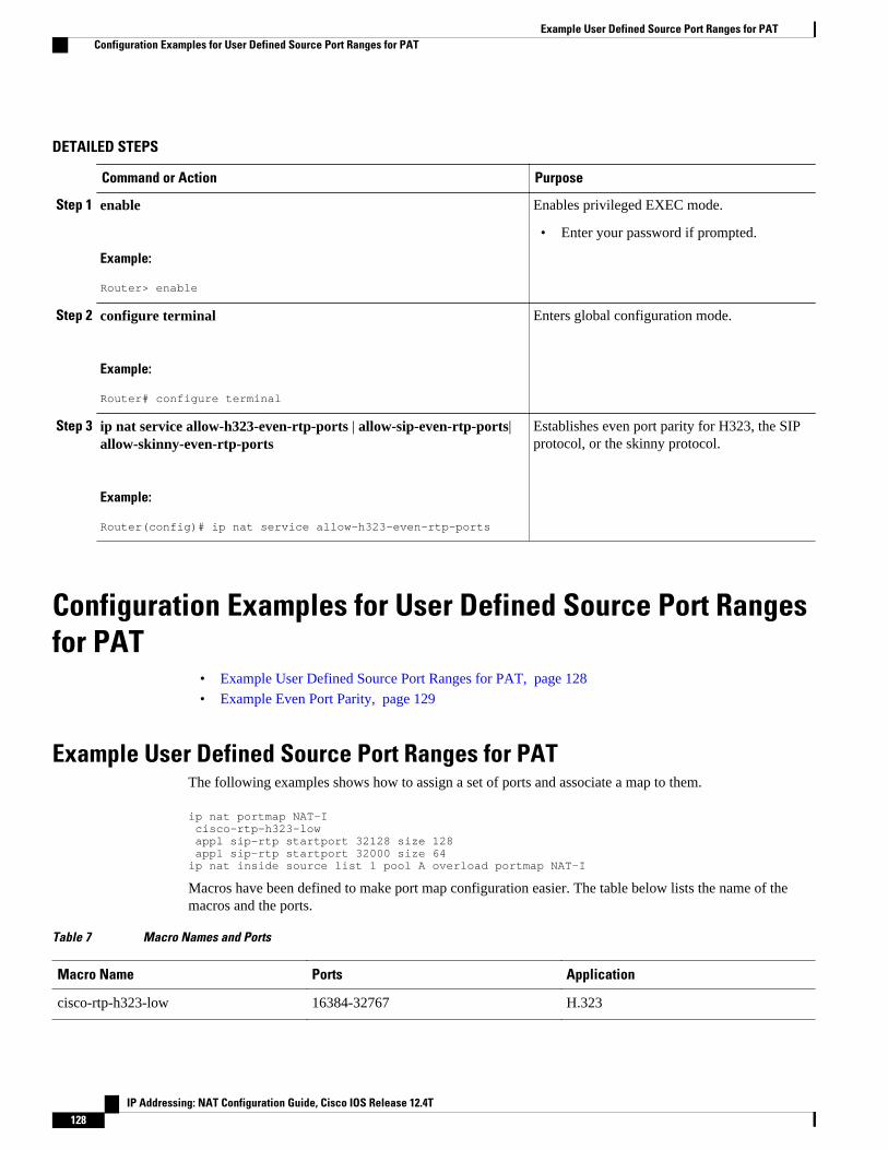
DETAILED STEPS
Command or Action Purpose
Step 1 enable
Example:
Router> enable
Enables privileged EXEC mode.
• Enter your password if prompted.
Step 2 configure terminal
Example:
Router# configure terminal
Enters global configuration mode.
Step 3 ip nat service allow-h323-even-rtp-ports | allow-sip-even-rtp-ports|allow-skinny-even-rtp-ports
Example:
Router(config)# ip nat service allow-h323-even-rtp-ports
Establishes even port parity for H323, the SIPprotocol, or the skinny protocol.
Configuration Examples for User Defined Source Port Rangesfor PAT
• Example User Defined Source Port Ranges for PAT, page 128
• Example Even Port Parity, page 129
Example User Defined Source Port Ranges for PATThe following examples shows how to assign a set of ports and associate a map to them.
ip nat portmap NAT-I cisco-rtp-h323-low appl sip-rtp startport 32128 size 128 appl sip-rtp startport 32000 size 64ip nat inside source list 1 pool A overload portmap NAT-I
Macros have been defined to make port map configuration easier. The table below lists the name of themacros and the ports.
Table 7 Macro Names and Ports
Macro Name Ports Application
cisco-rtp-h323-low 16384-32767 H.323
Example User Defined Source Port Ranges for PAT Configuration Examples for User Defined Source Port Ranges for PAT
IP Addressing: NAT Configuration Guide, Cisco IOS Release 12.4T128

Macro Name Ports Application
cisco-rtp-h323-high 49152-65535 H.323
cisco-rtp-skinny-low 16384-32767 Skinny
cisco-rtp-skinny-high 49152-65535 Skinny
cisco-rtp-sip-low 16384-32767 SIP
cisco-rtp-sip-high 49152-65535 SIP
Example Even Port ParityThe following example enables even port parity for H.323.
ip nat service allow-h323-even-rtp-ports
The following example enables even port parity for SIP.
ip nat service allow-sip-even-rtp-ports
The following example enables even port parity for the skinny protocol.
ip nat service allow-skinny-even-rtp-ports
Additional ReferencesRelated Documents
Related Topic Document Title
Cisco IOS commands Cisco IOS Master Commands List, All Releases
NAT commands: complete command syntax,command mode, defaults, usage guidelines, andexamples
Cisco IOS IP Addressing Services CommandReference
Standards
Standards Title
None --
Example Even Port ParityAdditional References
IP Addressing: NAT Configuration Guide, Cisco IOS Release 12.4T 129

MIBs
MIBs MIBs Link
• To locate and download MIBs for selectedplatforms, Cisco software releases, and feature sets,use Cisco MIB Locator found at the followingURL:
http://www.cisco.com/go/mibs
Technical Assistance
Description Link
The Cisco Support and Documentation websiteprovides online resources to downloaddocumentation, software, and tools. Use theseresources to install and configure the software andto troubleshoot and resolve technical issues withCisco products and technologies. Access to mosttools on the Cisco Support and Documentationwebsite requires a Cisco.com user ID andpassword.
http://www.cisco.com/cisco/web/support/index.html
Feature Information for User Defined Source Port Ranges forPAT
The following table provides release information about the feature or features described in this module.This table lists only the software release that introduced support for a given feature in a given softwarerelease train. Unless noted otherwise, subsequent releases of that software release train also support thatfeature.
Use Cisco Feature Navigator to find information about platform support and Cisco software image support.To access Cisco Feature Navigator, go to www.cisco.com/go/cfn. An account on Cisco.com is not required.
Table 8 Feature Information for User Defined Source Port Ranges for PAT
Feature Name Releases Feature Information
User Defined Source Port Rangesfor PAT
12.4(11)T The User Defined Source PortRanges for PAT feature enablesthe specification of source portranges for Port AddressTranslation (PAT) for SIP, H.323,and Skinny Real-Time TransportProtocol (RTP) and RTP ControlProtocol (RTCP).
User Defined Source Port Ranges for PAT Feature Information for User Defined Source Port Ranges for PAT
IP Addressing: NAT Configuration Guide, Cisco IOS Release 12.4T130

Cisco and the Cisco logo are trademarks or registered trademarks of Cisco and/or its affiliates in the U.S.and other countries. To view a list of Cisco trademarks, go to this URL: www.cisco.com/go/trademarks.Third-party trademarks mentioned are the property of their respective owners. The use of the word partnerdoes not imply a partnership relationship between Cisco and any other company. (1110R)
Any Internet Protocol (IP) addresses and phone numbers used in this document are not intended to beactual addresses and phone numbers. Any examples, command display output, network topology diagrams,and other figures included in the document are shown for illustrative purposes only. Any use of actual IPaddresses or phone numbers in illustrative content is unintentional and coincidental.
User Defined Source Port Ranges for PAT
IP Addressing: NAT Configuration Guide, Cisco IOS Release 12.4T 131

Example Even Port Parity
IP Addressing: NAT Configuration Guide, Cisco IOS Release 12.4T132

FPG Endpoint Agnostic Port Allocation
When the Endpoint Agnostic Port Allocation feature is configured, an entry is added to the SymmetricPort Database. If the entry is already available, the port listed in the Symmetric Port Database is used andthe packet is sent. This feature is only required if you need to configure NAT with pool overload orinterface overload. Endpoint Agnostic Port Allocation is also known as Symmetric Port Allocation.
• Finding Feature Information, page 133• Information About Endpoint Agnostic Port Allocation, page 133• How to Configure Endpoint Agnostic Port Allocation, page 134• Configuration Examples for Endpoint Agnostic Port Allocation, page 136• Additional References, page 137• Feature Information for Endpoint Agnostic Port Allocation, page 138
Finding Feature InformationYour software release may not support all the features documented in this module. For the latest featureinformation and caveats, see the release notes for your platform and software release. To find informationabout the features documented in this module, and to see a list of the releases in which each feature issupported, see the Feature Information Table at the end of this document.
Use Cisco Feature Navigator to find information about platform support and Cisco software image support.To access Cisco Feature Navigator, go to www.cisco.com/go/cfn. An account on Cisco.com is not required.
Information About Endpoint Agnostic Port AllocationWhen a packet is being transmitted, the Symmetric Port Database is checked to see if the requested port isalready allocated. If it has been allocated, it is checked if the source computer entry in the database matchesthe computer requesting the port. If this is true, the port listed in the Symmetric Port Database is used andthe packet is sent.
If the computers do not match or if the requested port is not in the Symmetric Port Database, the featurecontinues checks to the NAT Port database for an entry matching the requested port. If no entry is found,this means that the port is available. A new entry is added to the NAT Port database, and to the existingNAT database, allocating the port to the requesting computer, and the packet is sent.
If no matching entry in the NAT Port database is found, it means that the port is busy, or otherwiseunavailable. The next available port is found, which is allocated to the requesting computer. An entry isadded to the NAT Port database with the requesting computer and the available port. An entry is added tothe Symmetric Port database, with the requesting computer, the allocated port and the requested port andthe packet is sent.
IP Addressing: NAT Configuration Guide, Cisco IOS Release 12.4T 133

This feature is only required if you need to configure NAT with pool overload or interface overload. Thisfeature is not applicable for other NAT configurations.
How to Configure Endpoint Agnostic Port Allocation• Configuring Endpoint Agnostic Port Allocation, page 134
• Verifying Endpoint Agnostic Port Support, page 136
Configuring Endpoint Agnostic Port AllocationPerform this task to configure NAT to support the Endpoint Agnostic Port Allocation feature.
Note This feature must be enabled by the user. It should be enabled before NAT is enabled. If it is enabled later,it will not translate the previously established connection. When this feature is disabled, it will not be seenin the output of the show running-configcommand.
>
SUMMARY STEPS
1. enable
2. configure terminal
3. interface interface name
4. ip nat inside
5. exit
6. access list 1 permit ip address mask
7. ip nat inside source list 1 interface interface name
8. ip nat service enable-sym-port
9. exit
DETAILED STEPS
Command or Action Purpose
Step 1 enable
Example:
Router> enable
Enables privileged EXEC mode.
• Enter your password if prompted.
Configuring Endpoint Agnostic Port Allocation How to Configure Endpoint Agnostic Port Allocation
IP Addressing: NAT Configuration Guide, Cisco IOS Release 12.4T134

Command or Action Purpose
Step 2 configure terminal
Example:
Router# configure terminal
Enters global configuration mode.
Step 3 interface interface name
Example:
Router (config)# interface Ethernet 0/0
Configures the Ethernet 0/0 interface.
Step 4 ip nat inside
Example:
Router (config-if)# ip nat inside
Enables Network Address Translation (NAT)for the inside address.
Step 5 exit
Example:
Router (config-if)# exit
Exits interface configuration mode.
Step 6 access list 1 permit ip address mask
Example:
Router (config)# access list 1 permit 172.18.192.0.0.0.0.255
Creates an access list called 1.
Step 7 ip nat inside source list 1 interface interface name
Example:
Router (config)# ip nat inside source list 1 interface Ethernet 0/0
Enables NAT for the inside source for accesslist 1 which is attached to the Ethernetinterface.
Step 8 ip nat service enable-sym-port
Example:
Router (config)# ip nat service enable-sym-port
Enables the symmetric port allocation.
FPG Endpoint Agnostic Port AllocationHow to Configure Endpoint Agnostic Port Allocation
IP Addressing: NAT Configuration Guide, Cisco IOS Release 12.4T 135

Command or Action Purpose
Step 9 exit
Example:
Router(config)# exit
Exits global configuration mode.
Verifying Endpoint Agnostic Port SupportTo verify the Endpoint Agnostic Port Support feature, use the following command.
SUMMARY STEPS
1. show ip nat translations
DETAILED STEPS
show ip nat translations
Example:
Router# show ip nat translations NAT Symmetric Port Database: 1 entriespublic ipaddr:port [tableid] | port# [refcount][syscount] | localaddr:localport [flags]172.18.192.69:1024 [0] | 1025 [1] [0] | 172.18.192.69:1024 [0]
Configuration Examples for Endpoint Agnostic Port Allocation• Configuring Endpoint Allocation Example, page 136
Configuring Endpoint Allocation Exampleinterface Ethernet0/0 ip nat inside exitaccess list 1 permit 172.18.192.0.0.0.255ip nat inside source list 1 interface Ethernet0/0ip nat service enable-sym-portend
Verifying Endpoint Agnostic Port Support Configuration Examples for Endpoint Agnostic Port Allocation
IP Addressing: NAT Configuration Guide, Cisco IOS Release 12.4T136

Additional ReferencesRelated Documents
Related Topic Document Title
NAT configuration tasks “Configuring NAT for IP Address Conservation”module
NAT maintenance “Monitoring and Maintaining NAT” module
NAT commands: complete command syntax,command mode, command history, usageguidelines, and examples
Cisco IOS IP Addressing Services CommandReference
Standards
Standard Title
No new or modified standards are supported by thisfeature, and support for existing standards has notbeen modified by this feature.
_
MIBs
MIB MIBs Link
No new or modified MIBs are supported by thisfeature, and support for existing MIBs has not beenmodified by this feature.
To locate and download MIBs for selectedplatforms, Cisco IOS releases, and feature sets, useCisco MIB Locator found at the following URL:
http://www.cisco.com/go/mibs
RFCs
RFC Title
No new or modified RFCs are supported by thisfeature, and support for existing RFCs has not beenmodified by this feature.
_
FPG Endpoint Agnostic Port AllocationAdditional References
IP Addressing: NAT Configuration Guide, Cisco IOS Release 12.4T 137

Technical Assistance
Description Link
The Cisco Support and Documentation websiteprovides online resources to downloaddocumentation, software, and tools. Use theseresources to install and configure the software andto troubleshoot and resolve technical issues withCisco products and technologies. Access to mosttools on the Cisco Support and Documentationwebsite requires a Cisco.com user ID andpassword.
http://www.cisco.com/cisco/web/support/index.html
Feature Information for Endpoint Agnostic Port AllocationThe following table provides release information about the feature or features described in this module.This table lists only the software release that introduced support for a given feature in a given softwarerelease train. Unless noted otherwise, subsequent releases of that software release train also support thatfeature.
Use Cisco Feature Navigator to find information about platform support and Cisco software image support.To access Cisco Feature Navigator, go to www.cisco.com/go/cfn. An account on Cisco.com is not required.
Table 9 Feature Information for NAT Endpoint Agnostic Port Allocation
Feature Name Releases Feature Information
FPG: Endpoint Agnostic PortAllocation
12.4(24)T This feature was introduced.
Cisco and the Cisco logo are trademarks or registered trademarks of Cisco and/or its affiliates in the U.S.and other countries. To view a list of Cisco trademarks, go to this URL: www.cisco.com/go/trademarks.Third-party trademarks mentioned are the property of their respective owners. The use of the word partnerdoes not imply a partnership relationship between Cisco and any other company. (1110R)
Any Internet Protocol (IP) addresses and phone numbers used in this document are not intended to beactual addresses and phone numbers. Any examples, command display output, network topology diagrams,and other figures included in the document are shown for illustrative purposes only. Any use of actual IPaddresses or phone numbers in illustrative content is unintentional and coincidental.
FPG Endpoint Agnostic Port Allocation Feature Information for Endpoint Agnostic Port Allocation
IP Addressing: NAT Configuration Guide, Cisco IOS Release 12.4T138
NAT Optimized SIP Media Path Without SDP
The NAT Optimized SIP Media Path Without SDP feature provides the ability to optimize the media pathtaken by a SIP VoIP session when NAT is used. NAT forces the VoIP traffic to take at least one extra hopin the network, which usually results in several additional hops being added to the path between two IPhosts.
The Message Digest 5 (MD5) algorithm is supported.
• Finding Feature Information, page 139• Information About the NAT Optimized SIP Media Path Without SDP Feature, page 139• How to Configure NAT Optimized SIP Media Path Without SDP, page 140• Configuration Examples for NAT Optimized SIP Media Path Without SDP, page 142• Additional References, page 142• Feature Information for NAT Optimized SIP Media Path Without SDP, page 143
Finding Feature InformationYour software release may not support all the features documented in this module. For the latest featureinformation and caveats, see the release notes for your platform and software release. To find informationabout the features documented in this module, and to see a list of the releases in which each feature issupported, see the Feature Information Table at the end of this document.
Use Cisco Feature Navigator to find information about platform support and Cisco software image support.To access Cisco Feature Navigator, go to www.cisco.com/go/cfn. An account on Cisco.com is not required.
Information About the NAT Optimized SIP Media PathWithout SDP Feature
• Benefits of NAT Optimized SIP Media Path Without SDP, page 139
• NAT Optimized SIP Media Path Without SDP Feature Design, page 140
Benefits of NAT Optimized SIP Media Path Without SDP• The media path can be shortened, decreasing voice delay.• More control of voice policy is possible because the media path is closer to the customer domain and
not deep within the service provider cloud.
IP Addressing: NAT Configuration Guide, Cisco IOS Release 12.4T 139
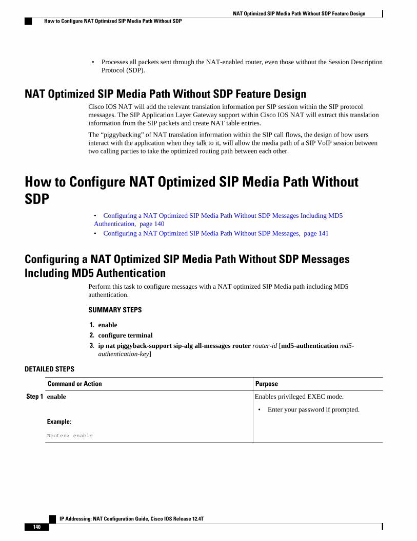
• Processes all packets sent through the NAT-enabled router, even those without the Session DescriptionProtocol (SDP).
NAT Optimized SIP Media Path Without SDP Feature DesignCisco IOS NAT will add the relevant translation information per SIP session within the SIP protocolmessages. The SIP Application Layer Gateway support within Cisco IOS NAT will extract this translationinformation from the SIP packets and create NAT table entries.
The “piggybacking” of NAT translation information within the SIP call flows, the design of how usersinteract with the application when they talk to it, will allow the media path of a SIP VoIP session betweentwo calling parties to take the optimized routing path between each other.
How to Configure NAT Optimized SIP Media Path WithoutSDP
• Configuring a NAT Optimized SIP Media Path Without SDP Messages Including MD5Authentication, page 140
• Configuring a NAT Optimized SIP Media Path Without SDP Messages, page 141
Configuring a NAT Optimized SIP Media Path Without SDP MessagesIncluding MD5 Authentication
Perform this task to configure messages with a NAT optimized SIP Media path including MD5authentication.
SUMMARY STEPS
1. enable
2. configure terminal
3. ip nat piggyback-support sip-alg all-messages router router-id [md5-authentication md5-authentication-key]
DETAILED STEPS
Command or Action Purpose
Step 1 enable
Example:
Router> enable
Enables privileged EXEC mode.
• Enter your password if prompted.
NAT Optimized SIP Media Path Without SDP Feature Design How to Configure NAT Optimized SIP Media Path Without SDP
IP Addressing: NAT Configuration Guide, Cisco IOS Release 12.4T140

Command or Action Purpose
Step 2 configure terminal
Example:
Router# configure terminal
Enters global configuration mode.
Step 3 ip nat piggyback-support sip-alg all-messages router router-id [md5-authentication md5-authentication-key]
Example:
Router(config)# ip nat piggyback-support sip-alg all-messages router 100 md5-authentication md5-key
Enables messages with a NAT optimized SIPMedia path including MD5 authentication.
Configuring a NAT Optimized SIP Media Path Without SDP MessagesPerform this task to configure SDP messages with a NAT optimized SIP Media path without MD5authentication.
SUMMARY STEPS
1. enable
2. configure terminal
3. ip nat piggyback-support sip-alg all-messages router router-id
DETAILED STEPS
Command or Action Purpose
Step 1 enable
Example:
Router> enable
Enables privileged EXEC mode.
• Enter your password if prompted.
Step 2 configure terminal
Example:
Router# configure terminal
Enters global configuration mode.
Configuring a NAT Optimized SIP Media Path Without SDP MessagesHow to Configure NAT Optimized SIP Media Path Without SDP
IP Addressing: NAT Configuration Guide, Cisco IOS Release 12.4T 141
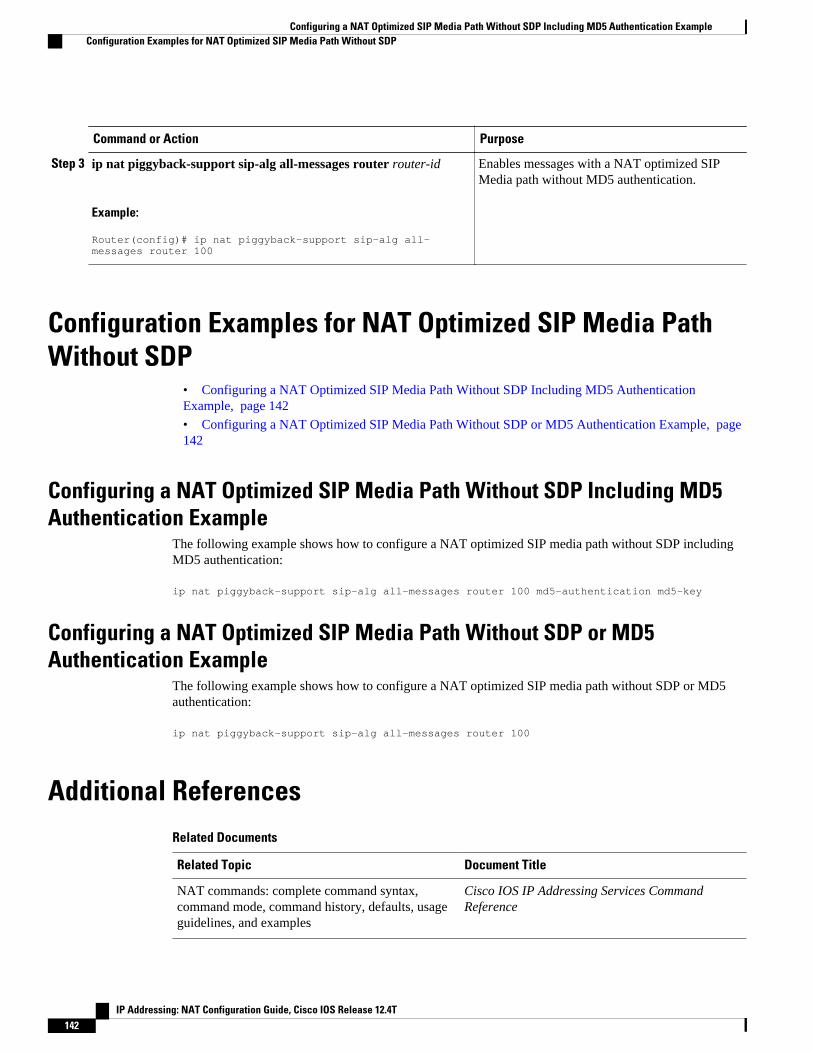
Command or Action Purpose
Step 3 ip nat piggyback-support sip-alg all-messages router router-id
Example:
Router(config)# ip nat piggyback-support sip-alg all-messages router 100
Enables messages with a NAT optimized SIPMedia path without MD5 authentication.
Configuration Examples for NAT Optimized SIP Media PathWithout SDP
• Configuring a NAT Optimized SIP Media Path Without SDP Including MD5 AuthenticationExample, page 142
• Configuring a NAT Optimized SIP Media Path Without SDP or MD5 Authentication Example, page142
Configuring a NAT Optimized SIP Media Path Without SDP Including MD5Authentication Example
The following example shows how to configure a NAT optimized SIP media path without SDP includingMD5 authentication:
ip nat piggyback-support sip-alg all-messages router 100 md5-authentication md5-key
Configuring a NAT Optimized SIP Media Path Without SDP or MD5Authentication Example
The following example shows how to configure a NAT optimized SIP media path without SDP or MD5authentication:
ip nat piggyback-support sip-alg all-messages router 100
Additional ReferencesRelated Documents
Related Topic Document Title
NAT commands: complete command syntax,command mode, command history, defaults, usageguidelines, and examples
Cisco IOS IP Addressing Services CommandReference
Configuring a NAT Optimized SIP Media Path Without SDP Including MD5 Authentication Example Configuration Examples for NAT Optimized SIP Media Path Without SDP
IP Addressing: NAT Configuration Guide, Cisco IOS Release 12.4T142

Standards
Standard Title
None --
MIBs
MIB MIBs Link
None To locate and download MIBs for selectedplatforms, Cisco IOS releases, and feature sets, useCisco MIB Locator found at the following URL:
http://www.cisco.com/go/mibs
RFCs
RFC Title
None --
Technical Assistance
Description Link
The Cisco Support and Documentation websiteprovides online resources to downloaddocumentation, software, and tools. Use theseresources to install and configure the software andto troubleshoot and resolve technical issues withCisco products and technologies. Access to mosttools on the Cisco Support and Documentationwebsite requires a Cisco.com user ID andpassword.
http://www.cisco.com/cisco/web/support/index.html
Feature Information for NAT Optimized SIP Media PathWithout SDP
The following table provides release information about the feature or features described in this module.This table lists only the software release that introduced support for a given feature in a given softwarerelease train. Unless noted otherwise, subsequent releases of that software release train also support thatfeature.
Use Cisco Feature Navigator to find information about platform support and Cisco software image support.To access Cisco Feature Navigator, go to www.cisco.com/go/cfn. An account on Cisco.com is not required.
NAT Optimized SIP Media Path Without SDPFeature Information for NAT Optimized SIP Media Path Without SDP
IP Addressing: NAT Configuration Guide, Cisco IOS Release 12.4T 143

Table 10 Feature Information for NAT Optimized SIP Media Path Without SDP
Feature Name Releases Feature Information
NAT Optimized SIP Media PathWithout SDP
12.4(2)T The NAT Optimized SIP MediaPath Without SDP featureprovides the ability to optimizethe media path taken by a SIPVoIP session when NAT is used.NAT forces the VoIP traffic totake at least one extra hop in thenetwork, which usually results inseveral additional hops beingadded to the path between two IPhosts.
Cisco and the Cisco logo are trademarks or registered trademarks of Cisco and/or its affiliates in the U.S.and other countries. To view a list of Cisco trademarks, go to this URL: www.cisco.com/go/trademarks.Third-party trademarks mentioned are the property of their respective owners. The use of the word partnerdoes not imply a partnership relationship between Cisco and any other company. (1110R)
Any Internet Protocol (IP) addresses and phone numbers used in this document are not intended to beactual addresses and phone numbers. Any examples, command display output, network topology diagrams,and other figures included in the document are shown for illustrative purposes only. Any use of actual IPaddresses or phone numbers in illustrative content is unintentional and coincidental.
NAT Optimized SIP Media Path Without SDP
IP Addressing: NAT Configuration Guide, Cisco IOS Release 12.4T144

NAT Optimized SIP Media Path with SDP
The NAT Optimized SIP Media Path with SDP feature allows the creation of a shorter path for SessionInitiation Protocol (SIP) media channels by distributing endpoint IP addressing information with SessionDescription Protocol (SDP) of SIP messages. This feature allows endpoints to communicate directly byusing standard routing and eliminates the need for them to traverse through upstream NAT routers.
The Message Digest 5 (MD5) algorithm is supported.
• Finding Feature Information, page 145• Information About the NAT Optimized SIP Media Path with SDP Feature, page 145• How to Configure NAT Optimized SIP Media Path with SDP, page 146• Configuration Examples for NAT Optimized SIP Media Path with SDP, page 148• Additional References, page 148• Feature Information for NAT Optimized SIP Media Path with SDP, page 150
Finding Feature InformationYour software release may not support all the features documented in this module. For the latest featureinformation and caveats, see the release notes for your platform and software release. To find informationabout the features documented in this module, and to see a list of the releases in which each feature issupported, see the Feature Information Table at the end of this document.
Use Cisco Feature Navigator to find information about platform support and Cisco software image support.To access Cisco Feature Navigator, go to www.cisco.com/go/cfn. An account on Cisco.com is not required.
Information About the NAT Optimized SIP Media Path withSDP Feature
• Restrictions for NAT Optimized SIP Media Path with SDP, page 145
• Benefits of NAT Optimized SIP Media Path with SDP, page 146
• NAT Optimized SIP Media Path with SDP Feature Design, page 146
Restrictions for NAT Optimized SIP Media Path with SDPSIP messages may or may not have SDP. This feature processes SIP messages with SDP only. If a callexchange with SDP is certain to occur, this feature should be used.
IP Addressing: NAT Configuration Guide, Cisco IOS Release 12.4T 145
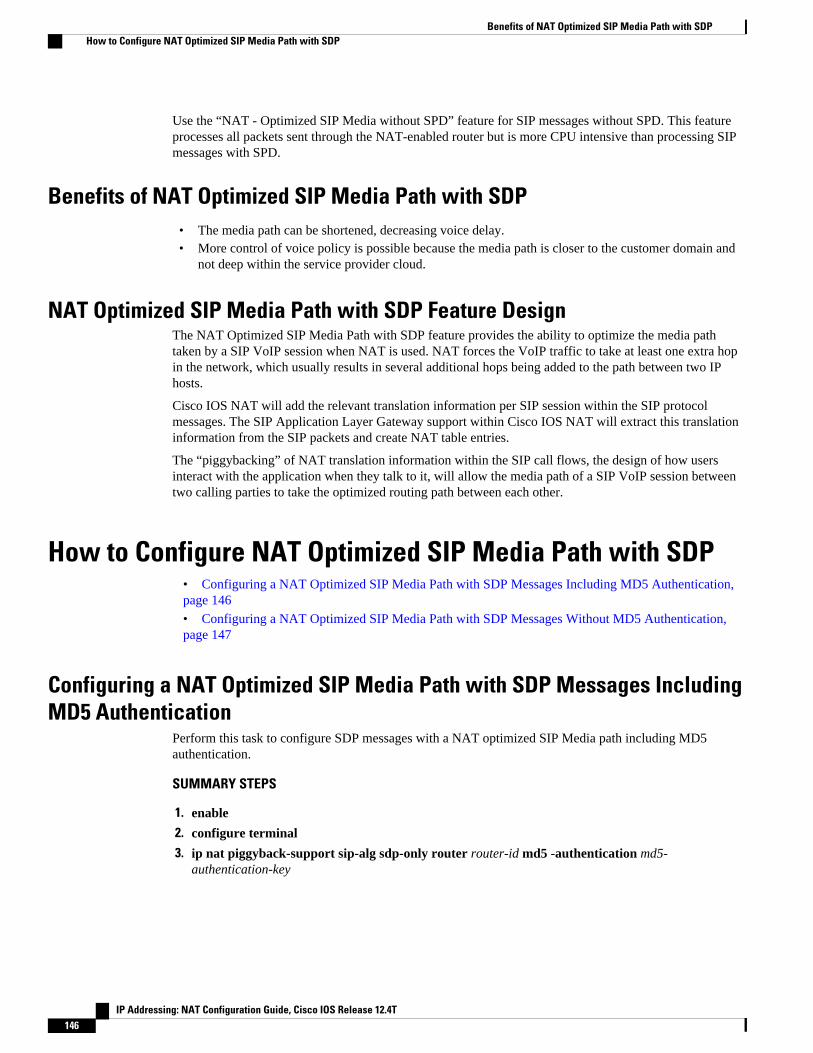
Use the “NAT - Optimized SIP Media without SPD” feature for SIP messages without SPD. This featureprocesses all packets sent through the NAT-enabled router but is more CPU intensive than processing SIPmessages with SPD.
Benefits of NAT Optimized SIP Media Path with SDP• The media path can be shortened, decreasing voice delay.• More control of voice policy is possible because the media path is closer to the customer domain and
not deep within the service provider cloud.
NAT Optimized SIP Media Path with SDP Feature DesignThe NAT Optimized SIP Media Path with SDP feature provides the ability to optimize the media pathtaken by a SIP VoIP session when NAT is used. NAT forces the VoIP traffic to take at least one extra hopin the network, which usually results in several additional hops being added to the path between two IPhosts.
Cisco IOS NAT will add the relevant translation information per SIP session within the SIP protocolmessages. The SIP Application Layer Gateway support within Cisco IOS NAT will extract this translationinformation from the SIP packets and create NAT table entries.
The “piggybacking” of NAT translation information within the SIP call flows, the design of how usersinteract with the application when they talk to it, will allow the media path of a SIP VoIP session betweentwo calling parties to take the optimized routing path between each other.
How to Configure NAT Optimized SIP Media Path with SDP• Configuring a NAT Optimized SIP Media Path with SDP Messages Including MD5 Authentication, page 146
• Configuring a NAT Optimized SIP Media Path with SDP Messages Without MD5 Authentication, page 147
Configuring a NAT Optimized SIP Media Path with SDP Messages IncludingMD5 Authentication
Perform this task to configure SDP messages with a NAT optimized SIP Media path including MD5authentication.
SUMMARY STEPS
1. enable
2. configure terminal
3. ip nat piggyback-support sip-alg sdp-only router router-id md5 -authentication md5-authentication-key
Benefits of NAT Optimized SIP Media Path with SDP How to Configure NAT Optimized SIP Media Path with SDP
IP Addressing: NAT Configuration Guide, Cisco IOS Release 12.4T146

DETAILED STEPS
Command or Action Purpose
Step 1 enable
Example:
Router> enable
Enables privileged EXEC mode.
• Enter your password if prompted.
Step 2 configure terminal
Example:
Router# configure terminal
Enters global configuration mode.
Step 3 ip nat piggyback-support sip-alg sdp-only router router-id md5 -authentication md5-authentication-key
Example:
Router(config)# ip nat piggyback-support sip-alg sdp-only router 100 md5-authentication md5-key
Enables SDP messages with a NAT optimizedSIP Media path including MD5authentication.
Configuring a NAT Optimized SIP Media Path with SDP Messages WithoutMD5 Authentication
Perform this task to configure SDP messages with a NAT optimized SIP Media path without MD5authentication.
SUMMARY STEPS
1. enable
2. configure terminal
3. ip nat piggyback-support sip-alg sdp-only router router-id
DETAILED STEPS
Command or Action Purpose
Step 1 enable
Example:
Router> enable
Enables privileged EXEC mode.
• Enter your password if prompted.
Configuring a NAT Optimized SIP Media Path with SDP Messages Without MD5 AuthenticationHow to Configure NAT Optimized SIP Media Path with SDP
IP Addressing: NAT Configuration Guide, Cisco IOS Release 12.4T 147
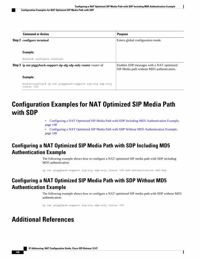
Command or Action Purpose
Step 2 configure terminal
Example:
Router# configure terminal
Enters global configuration mode.
Step 3 ip nat piggyback-support sip-alg sdp-only router router-id
Example:
Router(config)# ip nat piggyback-support sip-alg sdp-only router 100
Enables SDP messages with a NAT optimizedSIP Media path without MD5 authentication.
Configuration Examples for NAT Optimized SIP Media Pathwith SDP
• Configuring a NAT Optimized SIP Media Path with SDP Including MD5 Authentication Example, page 148
• Configuring a NAT Optimized SIP Media Path with SDP Without MD5 Authentication Example, page 148
Configuring a NAT Optimized SIP Media Path with SDP Including MD5Authentication Example
The following example shows how to configure a NAT optimized SIP media path with SDP includingMD5 authentication:
ip nat piggyback-support sip-alg sdp-only router 100 md5-authentication md5-key
Configuring a NAT Optimized SIP Media Path with SDP Without MD5Authentication Example
The following example shows how to configure a NAT optimized SIP media path with SDP without MD5authentication:
ip nat piggyback-support sip-alg sdp-only router 100
Additional References
Configuring a NAT Optimized SIP Media Path with SDP Including MD5 Authentication Example Configuration Examples for NAT Optimized SIP Media Path with SDP
IP Addressing: NAT Configuration Guide, Cisco IOS Release 12.4T148

Related Documents
Related Topic Document Title
NAT commands: complete command syntax,command mode, command history, defaults, usageguidelines, and examples
Cisco IOS IP Addressing Services CommandReference
NAT Optimized SIP Media Path without SDPconfiguration tasks and conceptual information
“NAT - Optimized SIP Media without SPD”module
Standards
Standard Title
None --
MIBs
MIB MIBs Link
None To locate and download MIBs for selectedplatforms, Cisco IOS releases, and feature sets, useCisco MIB Locator found at the following URL:
http://www.cisco.com/go/mibs
RFCs
RFC Title
None --
Technical Assistance
Description Link
The Cisco Support and Documentation websiteprovides online resources to downloaddocumentation, software, and tools. Use theseresources to install and configure the software andto troubleshoot and resolve technical issues withCisco products and technologies. Access to mosttools on the Cisco Support and Documentationwebsite requires a Cisco.com user ID andpassword.
http://www.cisco.com/cisco/web/support/index.html
NAT Optimized SIP Media Path with SDPAdditional References
IP Addressing: NAT Configuration Guide, Cisco IOS Release 12.4T 149

Feature Information for NAT Optimized SIP Media Path withSDP
The following table provides release information about the feature or features described in this module.This table lists only the software release that introduced support for a given feature in a given softwarerelease train. Unless noted otherwise, subsequent releases of that software release train also support thatfeature.
Use Cisco Feature Navigator to find information about platform support and Cisco software image support.To access Cisco Feature Navigator, go to www.cisco.com/go/cfn. An account on Cisco.com is not required.
Table 11 Feature Information for <Phrase Based on Module Title>
Feature Name Releases Feature Information
NAT Optimized SIP Media Pathwith SDP
12.4(2)T The NAT Optimized SIP MediaPath with SDP feature allows thecreation of a shorter path forSession Initiation Protocol (SIP)media channels by distributingendpoint IP addressinginformation with SessionDescription Protocol (SDP) ofSIP messages. This feature allowsendpoints to communicatedirectly by using standard routingand eliminates the need for themto traverse through upstreamNAT routers.
Cisco and the Cisco logo are trademarks or registered trademarks of Cisco and/or its affiliates in the U.S.and other countries. To view a list of Cisco trademarks, go to this URL: www.cisco.com/go/trademarks.Third-party trademarks mentioned are the property of their respective owners. The use of the word partnerdoes not imply a partnership relationship between Cisco and any other company. (1110R)
Any Internet Protocol (IP) addresses and phone numbers used in this document are not intended to beactual addresses and phone numbers. Any examples, command display output, network topology diagrams,and other figures included in the document are shown for illustrative purposes only. Any use of actual IPaddresses or phone numbers in illustrative content is unintentional and coincidental.
NAT Optimized SIP Media Path with SDP Feature Information for NAT Optimized SIP Media Path with SDP
IP Addressing: NAT Configuration Guide, Cisco IOS Release 12.4T150

Monitoring and Maintaining NAT
This module describes how to:
• Monitor Network Address Translation (NAT) using translation information and statistics displays.• Maintain NAT by clearing NAT translations before the timeout has expired.• Enable logging of NAT translation by way of syslog to log and track system error messages,
exceptions, and other information.
• Finding Feature Information, page 151• Prerequisites for Monitoring and Maintaining NAT, page 151• Information About Monitoring and Maintaining NAT, page 151• How to Monitor and Maintain NAT, page 153• Examples for Monitoring and Maintaining NAT, page 158• Where to Go Next, page 159• Additional References, page 159• Feature Information for Monitoring and Maintaining NAT, page 160
Finding Feature InformationYour software release may not support all the features documented in this module. For the latest featureinformation and caveats, see the release notes for your platform and software release. To find informationabout the features documented in this module, and to see a list of the releases in which each feature issupported, see the Feature Information Table at the end of this document.
Use Cisco Feature Navigator to find information about platform support and Cisco software image support.To access Cisco Feature Navigator, go to www.cisco.com/go/cfn. An account on Cisco.com is not required.
Prerequisites for Monitoring and Maintaining NATBefore performing the tasks in this module, you must be familiar with the concepts described in the“Configuring NAT for IP Address Conservation” module and have NAT configured in your network.
Information About Monitoring and Maintaining NAT• NAT Display Contents, page 152
• Syslog Usage, page 153
IP Addressing: NAT Configuration Guide, Cisco IOS Release 12.4T 151
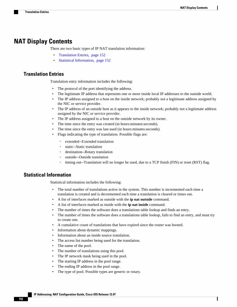
NAT Display ContentsThere are two basic types of IP NAT translation information:
• Translation Entries, page 152• Statistical Information, page 152
Translation EntriesTranslation entry information includes the following:
• The protocol of the port identifying the address.• The legitimate IP address that represents one or more inside local IP addresses to the outside world.• The IP address assigned to a host on the inside network; probably not a legitimate address assigned by
the NIC or service provider.• The IP address of an outside host as it appears to the inside network; probably not a legitimate address
assigned by the NIC or service provider.• The IP address assigned to a host on the outside network by its owner.• The time since the entry was created (in hours:minutes:seconds).• The time since the entry was last used (in hours:minutes:seconds).• Flags indicating the type of translation. Possible flags are:
◦ extended--Extended translation◦ static--Static translation◦ destination--Rotary translation◦ outside--Outside translation◦ timing out--Translation will no longer be used, due to a TCP finish (FIN) or reset (RST) flag.
Statistical InformationStatistical information includes the following:
• The total number of translations active in the system. This number is incremented each time atranslation is created and is decremented each time a translation is cleared or times out.
• A list of interfaces marked as outside with the ip nat outside command.• A list of interfaces marked as inside with the ip nat inside command.• The number of times the software does a translations table lookup and finds an entry.• The number of times the software does a translations table lookup, fails to find an entry, and must try
to create one.• A cumulative count of translations that have expired since the router was booted.• Information about dynamic mappings.• Information about an inside source translation.• The access list number being used for the translation.• The name of the pool.• The number of translations using this pool.• The IP network mask being used in the pool.• The starting IP address in the pool range.• The ending IP address in the pool range.• The type of pool. Possible types are generic or rotary.
NAT Display Contents Translation Entries
IP Addressing: NAT Configuration Guide, Cisco IOS Release 12.4T152

• The number of addresses in the pool available for translation.• The number of addresses being used.• The number of failed allocations from the pool.
NAT does not support ACL with the log option. The same functionality can be achieved by using one ofthe following options:
• By having a physical interface or VLAN with the logging option• By using NetFlow• By using the syslog feature
Syslog UsageSyslog Analysis lets you centrally log and track system error messages, exceptions, and other information(such as device configuration changes). You can use the logged error message data to analyze router andnetwork performance. You can customize Syslog Analysis to produce the information and message reportsimportant to your operation.
For more information see the Resource Manager Essentials and Syslog Analysis: How-Todocument:
http://www.cisco.com/warp/public/477/RME/rme_syslog.html
How to Monitor and Maintain NAT• Displaying NAT Translation Information, page 153
• Clearing NAT Entries Before the Timeout, page 155
• Enabling Syslog for Logging NAT Translations, page 157
Displaying NAT Translation Information
SUMMARY STEPS
1. enable
2. show ip nat translations [verbose]
3. show ip nat statistics
DETAILED STEPS
Command or Action Purpose
Step 1 enable
Example:Router> enable
Enables privileged EXEC mode.
• Enter your password if prompted.
Syslog UsageHow to Monitor and Maintain NAT
IP Addressing: NAT Configuration Guide, Cisco IOS Release 12.4T 153
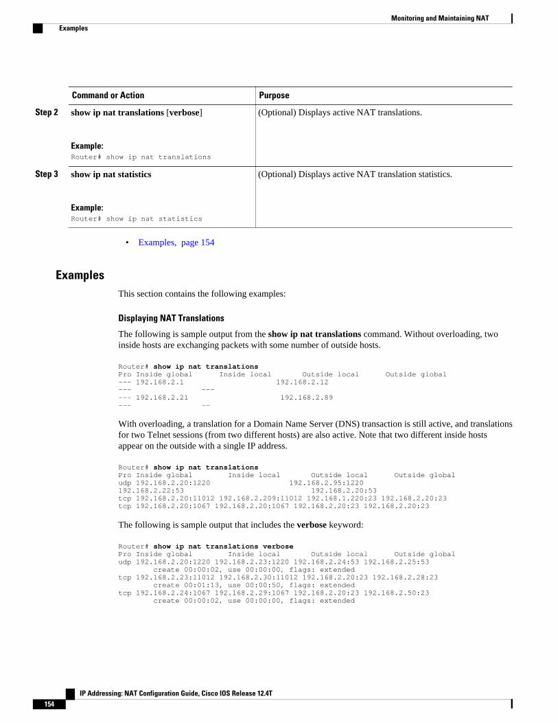
Command or Action Purpose
Step 2 show ip nat translations [verbose]
Example:Router# show ip nat translations
(Optional) Displays active NAT translations.
Step 3 show ip nat statistics
Example:Router# show ip nat statistics
(Optional) Displays active NAT translation statistics.
• Examples, page 154
ExamplesThis section contains the following examples:
Displaying NAT Translations
The following is sample output from the show ip nat translations command. Without overloading, twoinside hosts are exchanging packets with some number of outside hosts.
Router# show ip nat translationsPro Inside global Inside local Outside local Outside global--- 192.168.2.1 192.168.2.12 --- ------ 192.168.2.21 192.168.2.89 --- --
With overloading, a translation for a Domain Name Server (DNS) transaction is still active, and translationsfor two Telnet sessions (from two different hosts) are also active. Note that two different inside hostsappear on the outside with a single IP address.
Router# show ip nat translationsPro Inside global Inside local Outside local Outside globaludp 192.168.2.20:1220 192.168.2.95:1220 192.168.2.22:53 192.168.2.20:53tcp 192.168.2.20:11012 192.168.2.209:11012 192.168.1.220:23 192.168.2.20:23tcp 192.168.2.20:1067 192.168.2.20:1067 192.168.2.20:23 192.168.2.20:23
The following is sample output that includes the verbose keyword:
Router# show ip nat translations verbosePro Inside global Inside local Outside local Outside globaludp 192.168.2.20:1220 192.168.2.23:1220 192.168.2.24:53 192.168.2.25:53 create 00:00:02, use 00:00:00, flags: extendedtcp 192.168.2.23:11012 192.168.2.30:11012 192.168.2.20:23 192.168.2.28:23 create 00:01:13, use 00:00:50, flags: extendedtcp 192.168.2.24:1067 192.168.2.29:1067 192.168.2.20:23 192.168.2.50:23 create 00:00:02, use 00:00:00, flags: extended
Monitoring and Maintaining NAT Examples
IP Addressing: NAT Configuration Guide, Cisco IOS Release 12.4T154

Displaying NAT Statistics
The following is sample output from the show ip nat statistics command:
Router# show ip nat statisticsTotal translations: 2 (0 static, 2 dynamic; 0 extended)Outside interfaces: Serial0Inside interfaces: Ethernet1Hits: 135 Misses: 5Expired translations: 2Dynamic mappings:-- Inside Sourceaccess-list 1 pool net-208 refcount 2 pool net-208: netmask 255.255.255.240 start 192.168.0.0 end 192.168.255.255 type generic, total addresses 14, allocated 2 (14%), misses 0
Clearing NAT Entries Before the TimeoutBy default, dynamic address translations will time out from the NAT translation table at some point.Perform this task to clear the entries before the timeout.
SUMMARY STEPS
1. enable
2. clear ip nat translation inside global-ip local-ip outside local-ip global-ip
3. clear ip nat translation outside global-ip local-i p
4. clear ip nat translation protocol inside global-ip global-port local-ip local-port outside local-ip local-port-global-ip global-port
5. clear ip nat translation {* | [forced] | [inside global-ip local-ip] [outside local-ip global-ip]}
6. clear ip nat translation inside global-ip local-ip [forced]
7. clear ip nat translation outside local-ip global-ip [forced]
DETAILED STEPS
Command or Action Purpose
Step 1 enable
Example:
Router> enable
Enables privileged EXEC mode.
• Enter your password if prompted.
Clearing NAT Entries Before the TimeoutExamples
IP Addressing: NAT Configuration Guide, Cisco IOS Release 12.4T 155

Command or Action Purpose
Step 2 clear ip nat translation inside global-ip local-ipoutside local-ip global-ip
Example:
Router# clear ip nat translation inside 192.168.2.209 1220 192.168.2.95 1220
Example:
outside 192.168.2.100 53 192.168.2.101 53
(Optional) Clears a single dynamic half-entry containing an insidetranslation, or both inside and outside translation created in adynamic configuration.
• A dynamic half-entry will be cleared only if it does not haveany child translations.
Step 3 clear ip nat translation outside global-ip local-i p
Example:
Router# clear ip nat translation outside 192.168.2.100 1220 192.168.2.80
(Optional) Clears a single dynamic half-entry containing anoutside translation created in a dynamic configuration.
• A dynamic half-entry will be cleared only if it does not haveany child translations.
Step 4 clear ip nat translation protocol inside global-ipglobal-port local-ip local-port outside local-ip local-port-global-ip global-port
Example:
Router# clear ip nat translation udp inside 192.168.2.209 1220 192.168.2.195 1220
Example:
outside 192.168.2.13 53 192.168.2.132 53
(Optional) Clears a UDP translation entry.
Step 5 clear ip nat translation {* | [forced] | [inside global-ip local-ip] [outside local-ip global-ip]}
Example:
Router# clear ip nat translation *
(Optional) Clears either all dynamic translations (with the * orforced keyword), a single dynamic half-entry containing an insidetranslation, or a single dynamic half-entry containing an outsidetranslation.
• When clearing a single dynamic half-entry, it will be clearedonly if it does not have any child translations.
Step 6 clear ip nat translation inside global-ip local-ip[forced]
Example:
Router# clear ip nat translation *
(Optional) Forces the clearing of a single dynamic half-entry andits child translations containing an inside translation created in adynamic configuration, with or without its corresponding outsidetranslation.
• A dynamic half-entry will always be cleared, regardless ofwhether it has any child translations.
Monitoring and Maintaining NAT Examples
IP Addressing: NAT Configuration Guide, Cisco IOS Release 12.4T156

Command or Action Purpose
Step 7 clear ip nat translation outside local-ip global-ip[forced]
Example:
Router# clear ip nat translation *
(Optional) Forces the clearing of a single dynamic half-entry andits child translations containing an outside translation created in adynamic configuration.
• A dynamic half-entry will always be cleared, regardless ofwhether it has any child translations.
Enabling Syslog for Logging NAT TranslationsThe logging of NAT translations can be enabled and disabled by way of the syslog command.
Syslog Analysis lets you centrally log and track system error messages, exceptions, and other information(such as NAT translations). You can use the logged error message data to analyze router and networkperformance. You can customize Syslog Analysis to produce the information and message reportsimportant to your operation.
Prior to performing this task, you must specify the necessary syslog commands such as making sure thatlogging is enabled, configuring the server’s IP address, and establishing the level of messages to betrapped.
SUMMARY STEPS
1. enable
2. configure terminal
3. ip nat log translations syslog
4. no logging console
DETAILED STEPS
Command or Action Purpose
Step 1 enable
Example:
Router> enable
Enables privileged EXEC mode.
• Enter your password if prompted.
Step 2 configure terminal
Example:
Router# configure terminal
Enters global configuration mode.
Enabling Syslog for Logging NAT TranslationsExamples
IP Addressing: NAT Configuration Guide, Cisco IOS Release 12.4T 157

Command or Action Purpose
Step 3 ip nat log translations syslog
Example:
Router(config)# ip nat log translations syslog
Enables the syslog for logging NAT translations.
Step 4 no logging console
Example:
Router(config)# no logging console
(Optional) Disables the log display to the console.
• Logging to the console is enable by default.
Examples for Monitoring and Maintaining NAT• Clearing UDP NAT Translations Example, page 158
• Enabling Syslog Example, page 158
Clearing UDP NAT Translations ExampleThe following example shows the NAT entries before and after the User Datagram Protocol (UDP) entry iscleared:
Router# show ip nat translation
Pro Inside global Inside local Outside local Outside globaludp 192.168.2.20:1220 192.168.2.95:1220 192.168.2.22:53 192.168.2.20:53tcp 192.168.2.20:11012 192.168.2.209:11012 171.69.1.220:23 192.168.2.20:23tcp 192.168.2.20:1067 192.168.2.20:1067 192.168.2.20:23 192.168.2.20:23Router# clear ip nat translation udp inside 192.168.2.20:1067 192.168.2.20:1067 outside 192.168.2.20:23 192.168.2.20:23Router# show ip nat translation Pro Inside global Inside local Outside local Outside globaludp 192.168.2.20:1220 192.168.2.95:1220 192.168.2.22:53 192.168.2.20:53tcp 192.168.2.20:11012 192.168.2.209:11012 171.69.1.220:23 192.168.2.20:23
Enabling Syslog ExampleThe following example shows how to NAT entries into syslog.
Router(config)# logging onRouter(config)# logging 1.1.1.1Router(config)# logging trap informationalRouter(Config)# ip nat log translations syslog
Clearing UDP NAT Translations Example Examples for Monitoring and Maintaining NAT
IP Addressing: NAT Configuration Guide, Cisco IOS Release 12.4T158
The format of NAT information logged (for example, for ICMP Ping via NAT Overload configurations)will be as follows:
Apr 25 11:51:29 [10.0.19.182.204.28] 1: 00:01:13: NAT:Created icmp135.135.5.2:7 171 12.106.151.30:7171 54.45.54.45:717154.45.54.45:7171Apr 25 11:52:31 [10.0.19.182.204.28] 8: 00:02:15: NAT:Deleted icmp135.135.5.2:7 172 12.106.151.30:7172 54.45.54.45:717254.45.54.45:7172
Where to Go Next• To configure NAT for use with application level gateways, see the “Using Application Level
Gateways with NAT” module.• To integrate NAT with MPLS VPNs, see the “Integrating NAT with MPLS VPNs” module.• To configure NAT for high availability, see the “Configuring NAT for High Availability” module.
Additional ReferencesThe following sections provide references related to Monitoring and Maintaining NAT.
Related Documents
Related Topic Document Title
NAT commands: complete command syntax,command mode, command history, defaults, usageguidelines, and examples
"IP Addressing Commands" chapter in the CiscoIOS IP Command Reference, Volume 1 of 3:Addressing and Services, Release 12.3.
Standards
Standard Title
None --
MIBs
MIB MIBs Link
None To locate and download MIBs for selectedplatforms, Cisco IOS releases, and feature sets, useCisco MIB Locator found at the following URL:
http://www.cisco.com/go/mibs
RFCs
RFC Title
None --
Monitoring and Maintaining NATWhere to Go Next
IP Addressing: NAT Configuration Guide, Cisco IOS Release 12.4T 159
Technical Assistance
Description Link
The Cisco Support and Documentation websiteprovides online resources to downloaddocumentation, software, and tools. Use theseresources to install and configure the software andto troubleshoot and resolve technical issues withCisco products and technologies. Access to mosttools on the Cisco Support and Documentationwebsite requires a Cisco.com user ID andpassword.
http://www.cisco.com/cisco/web/support/index.html
Feature Information for Monitoring and Maintaining NATThe following table provides release information about the feature or features described in this module.This table lists only the software release that introduced support for a given feature in a given softwarerelease train. Unless noted otherwise, subsequent releases of that software release train also support thatfeature.
Use Cisco Feature Navigator to find information about platform support and Cisco software image support.To access Cisco Feature Navigator, go to www.cisco.com/go/cfn. An account on Cisco.com is not required.
Table 12 Feature Information for Monitoring and Maintaining NAT
Feature Name Releases Feature Information
NAT--Forced Clear of DynamicNAT Half-Entries
Cisco IOS 12.2 (33) XND A second forced keyword wasadded to the clear ip nattranslation command to enablethe removal of half-entriesregardless of whether they haveany child translations.
Cisco and the Cisco logo are trademarks or registered trademarks of Cisco and/or its affiliates in the U.S.and other countries. To view a list of Cisco trademarks, go to this URL: www.cisco.com/go/trademarks.Third-party trademarks mentioned are the property of their respective owners. The use of the word partnerdoes not imply a partnership relationship between Cisco and any other company. (1110R)
Any Internet Protocol (IP) addresses and phone numbers used in this document are not intended to beactual addresses and phone numbers. Any examples, command display output, network topology diagrams,and other figures included in the document are shown for illustrative purposes only. Any use of actual IPaddresses or phone numbers in illustrative content is unintentional and coincidental.
Monitoring and Maintaining NAT Feature Information for Monitoring and Maintaining NAT
IP Addressing: NAT Configuration Guide, Cisco IOS Release 12.4T160