ip fast reroute technologies - apricot · ip fast reroute technologies stefano previdi -...
TRANSCRIPT

1© 2006 Cisco Systems, Inc. All rights reserved.Stefano Previdi
IP Fast ReRoute Technologies
Stefano Previdi - [email protected]

222© 2006 Cisco Systems, Inc. All rights reserved.Stefano Previdi
Agenda
• Introduction
• Problem Definition
• Concepts
• Loop Free Alternate (LFA)
• Not-Via Addresses
• LFA/Not-Via Addresses Combined
• Conclusions

333© 2006 Cisco Systems, Inc. All rights reserved.Stefano Previdi
Introduction
• IP Fast Reroute refers to the set of technologiesaiming to provide fast rerouting capability usingpure IP forwarding and routing paradigm
• Similar service as delivered by MPLS when MPLS-TE-FRR is deployed
• Both “families” of FRR technologies (IP and MPLS)need to address the Microloop issue
Not covered on this presentation

PROBLEM DEFINITION
444© 2006 Cisco Systems, Inc. All rights reserved.

555© 2006 Cisco Systems, Inc. All rights reserved.Stefano Previdi
Problem Definition
• Loss of connectivity has different impact ondifferent applications
example: Voice vs. e-mails
• Loss of connectivity need to be addressed more precisely
For which routes?
Important IGP destinations (BGP Next-Hops, gateways,servers, …)
Recursive routes (IBGP/EBGP routes)
How Fast is required?:
Sub-Second: requirements for most IP networks
Sub-200ms: a few applications are sensitive to LoC <= 200ms
Sub-50ms: business requirement for some fraction of IP networks

666© 2006 Cisco Systems, Inc. All rights reserved.Stefano Previdi
Current StatusFast IGP Convergence
• In the last years, Cisco implementations (IOS and IOS-XR)have considerably improved convergence performance
• Sub-Second
Conservatively met by current technology
Deployed
• Sub-500ms
Achievable goal, issue is determinism
• Sub-50ms
Impossible

777© 2006 Cisco Systems, Inc. All rights reserved.Stefano Previdi
Current StatusFast IGP Convergence
• Fast Convergence of the IGP and its recursive routes:
Failure Detection (Sonet today, BFD emerging) < ~ 20ms
Origination < ~ 10ms
Queueing, Serialization, Propagation < 30ms
Flooding < 5 * 2ms = 10ms
SPF < n * 40us
FIB update: p * 100us
FIB Distribution Delay: 50ms
~ 100ms + p * 0.1 ms
500 important prefixes: ~ 150ms
• Worst-case over 100 iterations of most important prefixes: ~280ms for 1500 nodes and 2500 prefixes

888© 2006 Cisco Systems, Inc. All rights reserved.Stefano Previdi
Current StatusIPFRR and IETF
• IPFRR solutions emerged within Cisco and later in IETFcommunity in order to address convergence mechanisms thatwould allow re-routing times in the ~50 msecs order
• Several mechanisms have been defined documented
• IPFRR mechanisms are still under discussion within the IETFRouting Area Working Group
• Goals
Simplicity of deployment, operation and troubleshooting
Ability to cover 100% topological cases
Protect links, nodes and SRLGs

IP FAST REROUTE CONCEPTS
999© 2006 Cisco Systems, Inc. All rights reserved.

101010© 2006 Cisco Systems, Inc. All rights reserved.Stefano Previdi
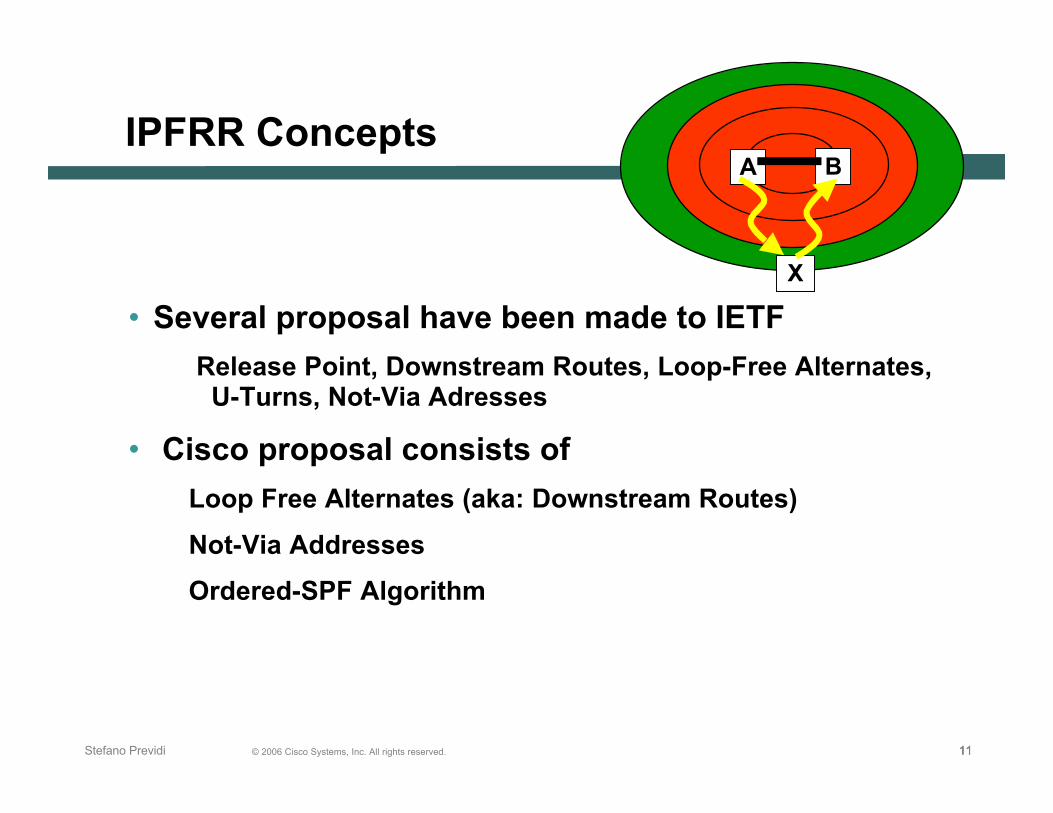
IPFRR Concepts
• When Link AB fails, only a subset ofthe network is impacted by thistopological change (red layers)
Maximal distance of wave-front having an effect
Fast Convergence project demonstrate that the size of the impacted area is limited
• Outside this subset routing is consistent (green layers)
• The scope of IPFRR is to find a point in the network that It is not impacted by the failure
Can be reached wether or not there’s a failure
Will forward traffic to any destination without using AB link
From there, all packets flow to their destination whileavoiding the failure (and without knowledge of thefailure)
A B
X
111111© 2006 Cisco Systems, Inc. All rights reserved.Stefano Previdi
A B
X
IPFRR Concepts
• Several proposal have been made to IETF
Release Point, Downstream Routes, Loop-Free Alternates, U-Turns, Not-Via Adresses
• Cisco proposal consists of
Loop Free Alternates (aka: Downstream Routes)
Not-Via Addresses
Ordered-SPF Algorithm

LOOP FREEALTERNATE ROUTES
121212© 2006 Cisco Systems, Inc. All rights reserved.
131313© 2006 Cisco Systems, Inc. All rights reserved.Stefano Previdi
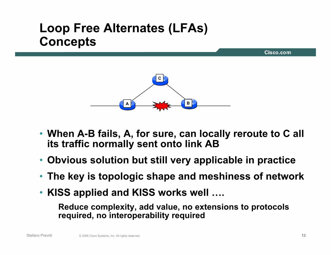
• When A-B fails, A, for sure, can locally reroute to C allits traffic normally sent onto link AB
• Obvious solution but still very applicable in practice
• The key is topologic shape and meshiness of network
• KISS applied and KISS works well ….Reduce complexity, add value, no extensions to protocolsrequired, no interoperability required
A
C
B
Loop Free Alternates (LFAs)Concepts

141414© 2006 Cisco Systems, Inc. All rights reserved.Stefano Previdi
Loop Free Alternate Routes (LFAs)Concepts
• Used when another neighbor can be safely used as an alternatenext-hop for protected traffic
• Upon BD link failure, B can safely reroute to C traffic it used tosend to D
No loop will be formed
C will forward to D and not back to B
• Pre-computation without any new topology information
B just leverages its link-state database
B
C
A ED
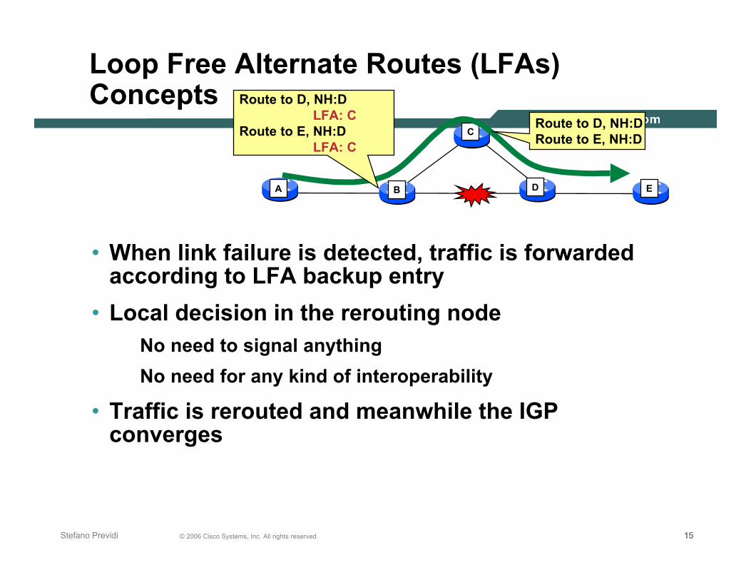
Route to D, NH:D LFA: CRoute to E, NH:D LFA: C
Route to D, NH:DRoute to E, NH:D
151515© 2006 Cisco Systems, Inc. All rights reserved.Stefano Previdi
B
C
A ED
Route to D, NH:D LFA: CRoute to E, NH:D LFA: C
Route to D, NH:DRoute to E, NH:D
Loop Free Alternate Routes (LFAs)Concepts
• When link failure is detected, traffic is forwardedaccording to LFA backup entry
• Local decision in the rerouting node No need to signal anything
No need for any kind of interoperability
• Traffic is rerouted and meanwhile the IGPconverges

161616© 2006 Cisco Systems, Inc. All rights reserved.Stefano Previdi
Loop Free Alternate Routes (LFAs)Concepts
• When IGP converges, nhop/if of primary pathis updated
• Pre-computation of backup’s is refreshedaccording to new topology
• LFA routes do not work in all cases Requires meshed topologies
Not always the case within core networks
B
C
A ED
Route to D, NH:CRoute to E, NH:D
Route to D, NH:DRoute to E, NH:D

171717© 2006 Cisco Systems, Inc. All rights reserved.Stefano Previdi
Loop Free Alternate Routes (LFAs)Concepts
• LFAs allow to repair IP and MPLS traffic
• IP traffic is simply rerouted towards the LFA next-hop
backup next-hop/interface
• MPLS requires that the outgoing packet uses thelabel advertised by the backup next-hop
All labels are kept thanks to Liberal Retention Mode of LDP

181818© 2006 Cisco Systems, Inc. All rights reserved.Stefano Previdi
Loop Free Alternate Routes (LFAs)MPLS
• B computes LFA IP and label information IP info from link-state LSDB
Label info from LDP/LIB
B
C
A ED
LIBP1: 15,C 11,D
Prefix P1
LDP label 10, prefix P1
LDP label 11, prefix P1
LDP label 12, prefix P1
LDP label 15, prefix P1
FIBP1: NH: D Label: 11 LFA: C LFA-label: 15

191919© 2006 Cisco Systems, Inc. All rights reserved.Stefano Previdi
Loop Free Alternate Routes (LFAs)Computation
• LFA routes are computed using Reverse SPF algorithm
• Reverse SPF is a regular SPF algorithm that takes into accountthe reverse metric of each node
The metric from child to parent
Pseudonode preference is inverted when move nodes from TENTto PATHS
• Neighbor at the other side of the protected link is the rootof the reverse SPF computed by the protecting node
In the above example, B will compute a reverse SPF rooted at D inorder to protect BD link
B
C
A ED
Link to be protected by router B

202020© 2006 Cisco Systems, Inc. All rights reserved.Stefano Previdi
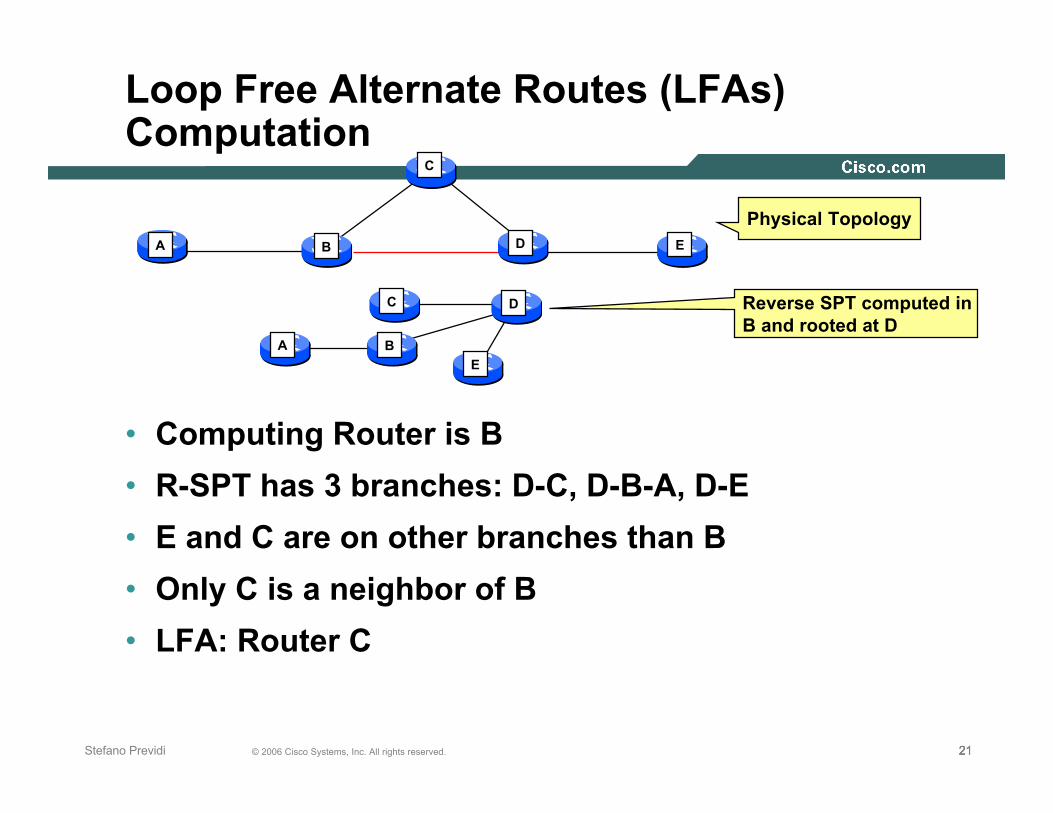
Loop Free Alternate Routes (LFAs)Computation
• B computes a reverse SPF rooted at D Neighbor at the other side of the protected link
• From computing router perspective, a valid LFA isa neighbor that does not belong to the sameSub-Tree (branch)
B
C
A ED
D
A
C
E
B
Physical Topology
Reverse SPT computed in B and rooted at D
212121© 2006 Cisco Systems, Inc. All rights reserved.Stefano Previdi
Loop Free Alternate Routes (LFAs)Computation
• Computing Router is B
• R-SPT has 3 branches: D-C, D-B-A, D-E
• E and C are on other branches than B
• Only C is a neighbor of B
• LFA: Router C
B
C
A ED
D
A
C
E
B
Physical Topology
Reverse SPT computed in B and rooted at D

222222© 2006 Cisco Systems, Inc. All rights reserved.Stefano Previdi
Loop Free Alternate Routes (LFAs)Computation
• Router A protects AB link
• R-SPT rooted at B gives C as valid LFA
• Regardless the metric configured on AC link, router A can safelyforward traffic to C
• C is a valid LFA for AB link protection
C is neighbor of A
C is on a different R-SPT branch
D
BA
C
B
C
A
D
Reverse SPT computed in A and rooted at B
Metric 10

232323© 2006 Cisco Systems, Inc. All rights reserved.Stefano Previdi
Loop Free Alternate Routes (LFAs)Types and Coverage
• Two types of LFAsNode Based
Prefix Based
• Node based LFAs require less computation but giveless coverage
LFA covers all prefixes originally reachable through theprotected link
• Prefix based increase coverage but requiremore computation
LFA is found for a subset of the prefixes originallyreachable through the protected link

242424© 2006 Cisco Systems, Inc. All rights reserved.Stefano Previdi
Loop Free Alternate Routes (LFAs)Prefix Based LFA
• No valid Node based LFA can be computed for protecting AB link
• There’s no neighbor of A residing on a different R-SPT branch(rooted at B)
• However, we know C is a valid LFA for a subset of the traffic
Traffic going to/through E
• In order to determine which prefixes can be protected, Acomputes SPF rooted at each of its neighbor
D
BA
C
C D
Reverse SPT computed in A and rooted at B
E
E
A
B

252525© 2006 Cisco Systems, Inc. All rights reserved.Stefano Previdi
Loop Free Alternate Routes (LFAs)Prefix Based LFA
• Router A determines which of the affectednodes/prefixes (in case of AB failure)can be routed to an LFA:
1- Determine the set of nodes/prefixes reachable through AB link
Information already available in the current SPT No computation is needed
2- Run SPF rooted at C
3- Find the intersection between
- Set computed in step-1
- Nodes/prefixes reachable not through AB link in SPT computed in step-2
• The intersection is the set of nodes/prefixes that can beprotected through LFA C in router A for AB link protection
D
BA
C
E

262626© 2006 Cisco Systems, Inc. All rights reserved.Stefano Previdi
Loop Free Alternate Routes (LFAs)Prefix Based LFA
• In case of AB link failure, router A can safely forward to C alltraffic originally destined through D and E.
• D and E is the intersection between sets 1 and 2
• A subset of the total traffic is protected
Traffic destined to D and E is protected
Traffic destined to B is NOT protected
D
BA
C
E
A
B C
DE
Set-1: A’s SPFSet of nodes reachable through AB link: B, D, E
C
D A
BE
Set-2: C’s SPFSet of nodes NOT reachable through AB link: A, D, E

272727© 2006 Cisco Systems, Inc. All rights reserved.Stefano Previdi
Loop Free Alternate Routes (LFAs)Coverage
• LFA routes do not work in all cases
• There’s no LFA route available in router A for protecting AB link
If router A forwards traffic originally sent though B to C, router C maysend it back to A and hence creates a loop
In the R-SPT computed by A and rooted at B there isn’t any neighborof A residing on a different branch
C is on same branch
• LFA requires a certain level of meshiness
Not always the case within core networks
D
BA
C
C
A
D
Reverse SPT computed in A and rooted at B
B

282828© 2006 Cisco Systems, Inc. All rights reserved.Stefano Previdi
IPFRR ArchitectureLFA solution in practice: SP #1
• Total traffic : 216459 units
Based on real traffic matrix
• Protectable traffic : 166482 (76.9 %)
84.9% of the intrapop traffic is protectable
70.9% of the interpop traffic is protectable
• Directed links carrying traffic : 756
358 intrapop links (out of 486) are protectable
187 interpop links (out of 270) are protectable

292929© 2006 Cisco Systems, Inc. All rights reserved.Stefano Previdi
IPFRR ArchitectureLFA solution in practice: SP #2
• Total traffic 672869 units Based on uniform matrix
Key is topologic “shape” of network design
• Protectable traffic : 483522 units (71%) 89% of intrapop traffic is protectable
51% of interpop traffic is protectable
• Directed links carrying traffic : 1454 1256 of those links (86%) can be protected
1022 intrapop links (out of 1116) can be protected
234 interpop links (out of 338) can be protected

303030© 2006 Cisco Systems, Inc. All rights reserved.Stefano Previdi
Loop Free Alternate Routes (LFAs)Summary
• LFA routes are easy to compute
• No dignaling, no interoperability, no overhead
• RIB and FIB entries are populated with backup information(on a per prefix basis)
• MPLS supported
• Failure detection is similar to the one implemented for MPLS-FRR
• LFA routes require meshed topologies
• Not always realistic in real backbones
• According to surveys, 70 to 85 percent of the topology cases
Good start

313131© 2006 Cisco Systems, Inc. All rights reserved.Stefano Previdi
Loop Free Alternate Routes (LFAs)Summary
• LFA Requires a few SPF/R-SPF computations to be run on eachnode protecting links
Reasonable amount of computations
Not an issue for today’s router platforms
More memory used to store backup paths
• LFA computation are typically run in background (not impactingnetwork convergence)
• Gradual deployment, no flag day
No interoperability requirement
• Little routing protocol extensions
• LFAs do allow good but not complete protection coverage
Around 70% - 80% in most current topologies
• Work well in MPLS networks

IPFRR Not-Via Addresses
323232© 2006 Cisco Systems, Inc. All rights reserved.

333333© 2006 Cisco Systems, Inc. All rights reserved.Stefano Previdi
A B
Protected link
CD
IPFRR ArchitectureNot-Via Addresses
• Pre-computed repair paths
• B advertises a special-purpose IP address: Not-Via address
• In router B, the AB link has now two addresses
Regular IP address of B
Not-Via address of B whose meaning is:
Don’t use this link to reach B (aka: B-Not-Via-A)
Purpose is to reach B without going through A
• A, C and D (and any other node in the network) compute apath to the Not-Via address advertised by B
• Once computed, the path to reach B-Not-Via-A doesn’t includeAB link

343434© 2006 Cisco Systems, Inc. All rights reserved.Stefano Previdi
A B
Protected link
CD
IPFRR ArchitectureNot-Via Addresses
• Upon failure detection A encapsulates(tunnels) traffic to the Not-Via address advertisedby B and pre-computed by A, C and D.
• Traffic is tunnelled around the failureEach hop in the path has computed the same path to theNot-Via address
• The path taken but the Not-Via addresses cantraverse routers that are affected by the failure
Not-Via address semantic exclude the failed link anyway

353535© 2006 Cisco Systems, Inc. All rights reserved.Stefano Previdi
IPFRR ArchitectureNot-Via Addresses
• Each router advertises two IP addresses per link
One for “normal” IP purpose
One for IPFRR purposes
Not-Via address
• Not-Via addresses gets a label assigned as any other IP prefix
• Scope of Not-Via address is different
Reach originator of the address without using the link the Not-Viaaddress has been assigned to
• Each router in the routing area receive and stores otherrouters Link State Packets with
Topology information
IP addresses
Not-Via addresses
363636© 2006 Cisco Systems, Inc. All rights reserved.Stefano Previdi
IPFRR ArchitectureNot-Via Addresses Computation
• Not-Via addresses are intended to be use only forrepair traffic
• After the regular SPF is computed, each router haveto compute a special SPF
For each known Not-Via address in the LSDB
• Several optimizations have been defined in order toreduce computation complexity of not-Viaaddresses

373737© 2006 Cisco Systems, Inc. All rights reserved.Stefano Previdi
IPFRR ArchitectureNot-Via Addresses Computation
• Optimization 1: Check whether the Not-Via address belongs toa link that is used in the current topology
If not, there’s no need to compute anything
Not-Via address inherit the NH information form current topology
• Optimization 2: Incremental-SPF with Early Termination
Each Not-Via address is computed through I-SPF algorithm
As soon as the path is found, I-SPF algorithm is stopped
Fast, optimal, small overhead
• Optimization 3: Check if any LFA exist and has beencomputed for the Not-Via address link
See next section…

383838© 2006 Cisco Systems, Inc. All rights reserved.Stefano Previdi
IPFRR ArchitectureNot-Via Addresses
The semantic of Not-Via address 10.1.1.1/32 is: reach router-A without going through router-B
A
B
E
C
D
Interface blah-blahip address 192.168.10.1/24Not-Via address 10.1.1.1/32
Interface blah-blahip address 192.168.10.2/24Not-Via address 10.1.1.2/32
The semantic of Not-Via address 10.1.1.2/32 is: reach router-B without going through router-A

393939© 2006 Cisco Systems, Inc. All rights reserved.Stefano Previdi
A
B
E
C
D
Interface blah-blahip address 192.168.10.1/24Not-Via address 10.1.1.1/32
Interface blah-blahip address 192.168.10.2/24Not-Via address 10.1.1.2/32
IPFRR ArchitectureNot-Via Addresses
A
B
E
C
D
Router-A SPT
A
B
E
C
D
Router-A SPT for Not-Via address 10.1.1.2
B
D
C
A
E
Router-B SPT
B
D
C
A
E
Router-B SPT for Not-Via address 10.1.1.2
Physical Topology

404040© 2006 Cisco Systems, Inc. All rights reserved.Stefano Previdi
IPFRR ArchitectureNot-Via Addresses
• Not-Via addresses are intended to be used only for repair traffic
• Each router will compute
Regular SPF for the routing area topology
For each Not-Via address advertised in the network
Prune the link the Not-Via address is assigned to
Compute I-SPF and compute Not-Via address path
• One I-SPF per Not-Via address
Means several hundreds (maybe thousands) of I-SPF
Problem ?
I-SPF is very well optimized for this kind of computation
I-SPF optimization: early termination
Simulation on real topologies gives up to 15 times full SPF for a600 nodes backbone where each link is to be protected

414141© 2006 Cisco Systems, Inc. All rights reserved.Stefano Previdi
A
B
E
C
D
Interface blah-blahip address 192.168.10.1/24Not-Via address 10.1.1.1/32
Interface blah-blahip address 192.168.10.2/24Not-Via address 10.1.1.2/32
Physical Topology
Not-Via AddressesUnicast Traffic
• On link failure, router Aencapsulates all trafficpreviously going throughrouter C and sends ittowards Not-Via address:10.1.1.2
• Each router has already computed a path for Not-Via address10.1.1.2 and such path does NOT traverse AC link
• Traffic is IP routed hop by hop towards router C
• Router C decapsulates traffic and continue “ordinary”IP routing

424242© 2006 Cisco Systems, Inc. All rights reserved.Stefano Previdi
A
B
E
C
D
Interface blah-blahip address 192.168.10.1/24Not-Via address 10.1.1.1/32
Interface blah-blahip address 192.168.10.2/24Not-Via address 10.1.1.2/32
Not-Via AddressesMulticast Traffic
• Multicast traffic is forwarded according to multicast states
Generated using PIM
RPF info used in order to validate incoming packets
• A protects multicast traffic using Not-Via address 10.1.1.2
Multicast traffic is encapsulated and sent towards C
• C decapsulates incoming traffic having 10.1.1.2 asdest address
Multicast traffic is checked against RPF info for the (S,G) state
Not-Via address 10.1.1.2 is associated with AC link in router C sothat RPF check succeeds

434343© 2006 Cisco Systems, Inc. All rights reserved.Stefano Previdi
A
B
E
C
D
Interface blah-blahip address 192.168.10.1/24Not-Via address 10.1.1.1/32
Interface blah-blahip address 192.168.10.2/24Not-Via address 10.1.1.2/32
Not-Via AddressesMPLS Traffic
• Traffic is encapsulated into the Not-Via address
• Not-Via address are known in the whole network
• An LDP label has been bound and advertised byeach router for each known Not-Via address
• Traffic tunnelled into a Not-Via address uses theNot-Via address label
Normal MPLS forwarding

444444© 2006 Cisco Systems, Inc. All rights reserved.Stefano Previdi
IPFRR ArchitectureNot-Via Addresses
• Both IP and MPLS traffic is protected
Unicast and Multicast
• IP traffic is encapsulated into the Not-Viaaddress header
IPinIP, GRE, L2TPv3, MPLS, …
• MPLS traffic is encapsulated into the Not-Via label
Not-Via addresses are IP addresses for which a label canbe advertised by LDP

454545© 2006 Cisco Systems, Inc. All rights reserved.Stefano Previdi
IPFRR ArchitectureNot-Via Addresses
• Not-Via require more computation than LFAEach router has to compute as many I-SPFs there are Not-Via addresses in the whole network
Optimized I-SPFs in order to reduce computation
According to simulations on real networks, up to 15 times aregular SPF is needed
Acceptable and deployable
• Not-Via require interoperability among all routers inthe network

464646© 2006 Cisco Systems, Inc. All rights reserved.Stefano Previdi
IPFRR ArchitectureNot-Via Addresses
• Not-Via allow 100% protection coverage (IP, MPLS,Multicast) in all topologies
• Not-Via addresses allows to protect traffic againstLink failure
Node failures
SRLG failures
• Requires tunnelling

IPFRR LFAS COMBINED WITHNOT-VIA ADDRESSES
© 2006 Cisco Systems, Inc. All rights reserved.

484848© 2006 Cisco Systems, Inc. All rights reserved.Stefano Previdi
A B
Protected link
CD
IPFRR ArchitectureNot-Via/LFA Combination
• Need for a solution that combines LFAs and Not-Viaaddresses
LFAs allow 70% - 80% of protection coverage
Not-Via addresses to fill the gap
Less Not-Via addresses to compute

494949© 2006 Cisco Systems, Inc. All rights reserved.Stefano Previdi
A B
Protected link
CD
IPFRR ArchitectureNot-Via/LFA Combination
• One I-SPF per Not-Via address my be seen as ascaling issue
Not all vendors have I-SPF implementations
Not all platform have enough CPU/memory capabilities
• Need interoperability in the network forNot-Via addresses
• Routers not protecting links/node may still have tosupport Not-Via addresses if they are in the path ofa Not-Via path

505050© 2006 Cisco Systems, Inc. All rights reserved.Stefano Previdi
A B
Protected link
CD
IPFRR ArchitectureNot-Via/LFA Combination
• Router A tries to compute LFA for A-B link protection
• If LFA is found, no need to compute any Not-Via address path
• Router A signals that LFA as been computed for A-Blink protection
• Routers C and D need not to compute any Not-Via address forA-B link
Even if a Not-via address has been advertised
• Constraint: Multicast Traffic protection is not always possiblewith LFAs

515151© 2006 Cisco Systems, Inc. All rights reserved.Stefano Previdi
A
B
E
C
D
Interface blah-blahip address 192.168.10.1/24Not-Via address 10.1.1.1/32
Interface blah-blahip address 192.168.10.2/24Not-Via address 10.1.1.2/32
IPFRR ArchitectureNot-Via/LFA Combination
• Router A has found an LFA for AC link protection:LFA-B
• Router A originates a new version of its link-statepacket with a flag stating the AC link is protected
Example:
ISIS TLV-22 (IS_NEIGHBOR_EXTENDED TLV)
Link_Attribute Sub-TLV (one bit used for LFA protection)

525252© 2006 Cisco Systems, Inc. All rights reserved.Stefano Previdi
A
B
E
C
D
IPFRR ArchitectureNot-Via/LFA Combination
• Any router in the area will start computingNotVia addresses
Step-1: compute base topology (regular SPF)
Step-2: for each NotVia address found
Step-2.1: Check whether the link associated to the NotVia address is in base SPT
If not, skip this address and inspect next one
Step-2.2: Check whether the link associated to the NotVia address has been flagged as LFA-Protected
If yes, skip this address and inspect next one
(easy to check during TWCC)
Step-2.3: Prune link and compute I-SPF on base topology
Step-2.3.1: During I-SPF if path to not-Via address is found stop and inspect next Not-Via address
Optimization 1
Optimization 3
Optimization 2

535353© 2006 Cisco Systems, Inc. All rights reserved.Stefano Previdi
IPFRR ArchitectureNot-Via/LFA Combination
• Each router needs to compute a path to eachNotVia address
• One SPF required for each NotVia address inthe network
Not strictly required but…
• Computation optimization significantly reducethe complexity
• According to simulations on real networks, up to 15times a regular SPF is needed
Acceptable and deployable

545454© 2006 Cisco Systems, Inc. All rights reserved.Stefano Previdi
Not-Via/LFA CombinationSummary
• Leverage LFA routes where possible (majority oflinks in topology)
• When LFA is used, it is signalled in the LSA/LSP
• New SubTLV used to identify type of protection
• Trigger NotVia computation only for cases whereLFAs are not possible

CONCLUSIONS
© 2006 Cisco Systems, Inc. All rights reserved.

565656© 2006 Cisco Systems, Inc. All rights reserved.Stefano Previdi
Conclusions
• SubSecond Requirement
Fast IGP: available, conservative, deployed
• Sub-200ms Requirement
Fast IGP: More work for determinism and still milk a few 10’s of milliseconds
• Sub-50ms Requirement
MPLS FRR
Very mature technology, deployed
IPFRR
Emerging Technology in both Cisco and IETF
Create determinism for convergence events

575757© 2006 Cisco Systems, Inc. All rights reserved.Stefano Previdi
Conclusions
• Still need fast detection mechanisms
Sonet alarms
BFD
• Can apply KISS solution and get very real benefits orcomplete solution that requires further operational complexity
• KISS principle:
Link protection, p2p only, ECMP where possible
• Full solution must have 100% repair

585858© 2006 Cisco Systems, Inc. All rights reserved.Stefano Previdi
IETFwork in progress
• IETF Drafts under discussion
draft-bryant-shand-ipfrr-notvia-addresses
draft-francois-ordered-fib-00.txt
• Need input on operational requirements, filters, blacking outlinks, debugs, show commands, …
• Need to study impact on multiple AF’s
• Need to discuss cost/benefits and complexity of solutions
• Need to analyze deployment scenarios
Further modelling studies as well as real-world experience
• Need to discuss node vs link failure and Shared Risk Groups

595959© 2006 Cisco Systems, Inc. All rights reserved.Stefano Previdi
Q and A
595959

© 2006 Cisco Systems, Inc. All rights reserved.