(ip-pbx features) - aria technologies · 3.2 voice configuration ... is aria technologies...
TRANSCRIPT

OptiCon SBG-1000 User Manual
(IP-PBX Features)

OptiCon SBG-1000 User Manual (IP-PBX Features)
Revision History
ISSUE DATE DESCRIPTION OF CHANGES
1.0 2011, August Initial Release
1.1 2012, February Update for SBG S/W version A.0Au

OptiCon SBG-1000 User Manual (IP-PBX Features)
I
Table Of Contents
1. Introduction ...................................................................................... 1-1
1.1 Overview ............................................................................................................. 1-1
1.2 Hardware Components ...................................................................................... 1-2
1.3 Manual Application ............................................................................................ 1-3
1.3.1 Organization ............................................................................................. 1-3
1.3.2 Feature Information ................................................................................. 1-3
1.4 System Capacities .............................................................................................. 1-3
1.5 Hardware Description ........................................................................................ 1-5
1.6 Specifications ..................................................................................................... 1-6
2. Call Features ..................................................................................... 2-1
2.1 System Time ....................................................................................................... 2-1
2.1.1 LCD Date/Time Format Control .............................................................. 2-1
2.1.2 Auto Service Mode Control ..................................................................... 2-1
2.1.3 Day/Night/Timed Ring Mode ................................................................... 2-2
2.2 Call Forward ........................................................................................................ 2-3
2.3 Call Forward, Preset ........................................................................................... 2-6
2.4 Call Park .............................................................................................................. 2-7
2.5 Call Pick-up ......................................................................................................... 2-8
2.5.1 Directed Call Pick-Up ............................................................................. 2-8
2.5.2 Group Call Pick-Up................................................................................ 2-10
2.6 Call Transfer ..................................................................................................... 2-11
2.6.1 Call Transfer, Station ............................................................................ 2-11
2.6.2 Call Transfer, CO ................................................................................... 2-13
2.6.3 Call Transfer, Voice Mail ...................................................................... 2-14
2.7 Call Waiting/Camp-On ...................................................................................... 2-15
2.8 CO Access ........................................................................................................ 2-16
2.9 CO Queuing ...................................................................................................... 2-17
2.10 Three-Party Voice Conference ........................................................................ 2-18
2.11 Customer Site Name ........................................................................................ 2-19
2.12 FAX .................................................................................................................... 2-20
2.13 Delayed CO Ring .............................................................................................. 2-20
2.14 Delayed Auto Attendant ................................................................................... 2-21
2.15 Diagnostic/Maintenance .................................................................................. 2-22
2.16 Dial-by-Name .................................................................................................... 2-22

OptiCon SBG-1000 User Manual (IP-PBX Features)
II
2.17 DND (Do Not Disturb) ....................................................................................... 2-24
2.18 Emergency Call ................................................................................................ 2-25
2.19 Flexible Numbering Plan .................................................................................. 2-26
2.20 Headset Compatibility ...................................................................................... 2-26
2.21 Hold ................................................................................................................... 2-27
2.21.1 Hold ........................................................................................................ 2-27
2.21.2 Hold Recall ............................................................................................. 2-28
2.21.3 Automatic Hold ....................................................................................... 2-29
2.22 Call Routing by Caller Number ........................................................................ 2-30
2.23 IP Fax Relay, T.38 support ............................................................................... 2-31
2.24 LNR (Last Number Redial) ............................................................................... 2-31
2.25 MOH (Music-On-Hold) ...................................................................................... 2-32
2.26 Registration & Registration Table ................................................................... 2-33
2.27 Ringing Line Preference .................................................................................. 2-34
2.28 Speed Dial ......................................................................................................... 2-34
2.28.1 Display Security ..................................................................................... 2-34
2.28.2 Individual Speed Dial ............................................................................. 2-35
2.28.3 Common Speed Dial ............................................................................... 2-37
2.29 Station Groups ................................................................................................. 2-38
2.30 SMDR (Station Message Detail Recording) .................................................... 2-41
2.30.1 Call Cost Display .................................................................................... 2-41
2.30.2 SMDR Call Records ................................................................................ 2-42
2.30.3 Lost Call Recording ................................................................................ 2-44
2.31 System Admin Programming .......................................................................... 2-46
2.31.1 Keyset Administration ........................................................................... 2-46
2.31.2 Web Administration ................................................................................ 2-47
2.32 Traffic Analysis ................................................................................................. 2-48
2.32.1 Traffic Analysis, Attendant ................................................................... 2-50
2.32.2 Traffic Analysis, Call Reports ............................................................... 2-51
2.32.3 Traffic Analysis, H/W Usage ................................................................. 2-52
2.32.4 Traffic Analysis, CO Reports ................................................................ 2-53
2.33 VSF Integrated Auto Attd/Voice Mail .............................................................. 2-54
2.33.1 VSF ......................................................................................................... 2-54
2.33.2 VSF-Auto Attendant .............................................................................. 2-54
2.33.3 VSF Voice Mail ...................................................................................... 2-56
2.33.4 Company Directory ................................................................................ 2-66
2.33.5 Record VM Greeting using Call Routing ............................................... 2-67
2.33.6 Administrator Mailbox ........................................................................... 2-68
2.33.7 Announce Only Mailbox ......................................................................... 2-70
2.33.8 Message Cascade ................................................................................... 2-70
2.33.9 Class of Service Settings ....................................................................... 2-71

OptiCon SBG-1000 User Manual (IP-PBX Features)
III
2.33.10 Send Message ........................................................................................ 2-72
2.33.11 Distribution Lists .................................................................................... 2-73
2.33.12 Mark a message private ........................................................................ 2-74
2.33.13 Mark a message for delivery confirmation ........................................... 2-75
2.34 Wake-Up Alarm ................................................................................................. 2-76
2.35 Direct Station Select/Busy Lamp Field (DSS/BLF) ........................................ 2-77
2.36 Intercom Call (ICM Call) ................................................................................... 2-78
2.37 Intercom Call Hold ............................................................................................ 2-79
2.38 Intercom Caller Controlled ICM Signaling ...................................................... 2-80
2.39 Intercom Lock-Out ........................................................................................... 2-80
2.40 Intercom Step Call ............................................................................................ 2-81
2.41 Message Wait/Call Back .................................................................................. 2-82
2.41.1 Station Message Wait/Call Back ........................................................... 2-82
2.41.2 Message Wait Reminder Tone............................................................... 2-84
2.42 Paging ............................................................................................................... 2-85
2.42.1 Paging & All Call Paging ....................................................................... 2-85
2.42.2 Meet Me Page Answer........................................................................... 2-86
2.43 CO Ring Assignment ....................................................................................... 2-87
2.44 CO Line Release Guard Time .......................................................................... 2-88
2.45 IP Trunking ........................................................................................................ 2-89
2.45.1 SIP Service ............................................................................................. 2-89
2.46 Calling/Called Party Identification .................................................................. 2-90
2.47 Answering Machine Emulation ....................................................................... 2-91
2.48 Auto Called Number Redial (ACNR) ............................................................... 2-92
2.49 Auto Release Of [Speaker] .............................................................................. 2-93
2.50 Automatic Speaker Select ............................................................................... 2-94
2.51 Call Log Display ............................................................................................... 2-95
2.52 Call Wait ............................................................................................................ 2-95
2.53 DND - One Time DND ....................................................................................... 2-96
2.54 Flex Button Direct Speed Dial Assignment .................................................... 2-97
2.55 Intercom Answer Mode .................................................................................... 2-98
2.56 Mute ................................................................................................................... 2-99
2.57 Off-Hook Signaling ......................................................................................... 2-100
2.58 On-Hook Dialing ............................................................................................. 2-101
2.59 Save Number Redial (SNR) ............................................................................ 2-102
2.60 Speakerphone ................................................................................................. 2-103
2.61 Station Flexible Buttons ................................................................................ 2-104
2.62 Station User Programming & Codes ............................................................ 2-105
2.63 Voice Over....................................................................................................... 2-108

OptiCon SBG-1000 User Manual (IP-PBX Features)
IV
2.64 Attendant Position ......................................................................................... 2-109
2.65 Attendant Recall ............................................................................................. 2-109
2.66 Attendant Station Program Codes ................................................................ 2-110
2.67 Attendant Call/Queuing.................................................................................. 2-112
2.68 Disable Outgoing CO Access ........................................................................ 2-113
2.69 Feature Cancel ................................................................................................ 2-113
2.70 SLT Broker Call .............................................................................................. 2-114
2.71 SLT Howler Tone ............................................................................................ 2-116
2.72 Dialing Restrictions ........................................................................................ 2-116
2.72.1 Class of Service ................................................................................... 2-116
2.72.2 Day, Night & Timed Station COS ........................................................ 2-117
2.72.3 Temporary Station COS/Lock ............................................................. 2-118
2.73 SIP Extension Service .................................................................................... 2-119
2.74 Prime Line Immediately/Delayed ................................................................... 2-120
2.75 International Call Restriction ......................................................................... 2-122
2.76 IP System DECT ............................................................................................. 2-122
2.77 Alarm Signal/Door Bell................................................................................... 2-124
2.78 Door Open ....................................................................................................... 2-125
2.79 Mobile Extension ............................................................................................ 2-126
2.80 System Networking ........................................................................................ 2-127
2.80.1 Distributed Control Network ............................................................... 2-127
2.81 Station Call Coverage .................................................................................... 2-132
2.82 IP Call Recording ............................................................................................ 2-133
2.83 Authorization Codes (Password) .................................................................. 2-135
2.84 USB Upgrade .................................................................................................. 2-136
2.85 Auto Call Recording ....................................................................................... 2-137
2.86 Two-way Record ............................................................................................. 2-138
2.87 Executive/Secretary Forward ........................................................................ 2-139
3. Web administration ........................................................................... 3-1
3.1 Voice Installation ................................................................................................ 3-1
3.1.1 System ...................................................................................................... 3-2
3.1.2 Station Registration.................................................................................. 3-3
3.1.3 CO Line Registration ................................................................................ 3-4
3.1.4 Auto Attendant ......................................................................................... 3-9
3.1.5 FAX ......................................................................................................... 3-10
3.1.6 Numbering Plan ...................................................................................... 3-10
3.2 Voice Configuration ......................................................................................... 3-11
3.2.1 Station Data ............................................................................................ 3-11
3.2.2 CO Line Data .......................................................................................... 3-16

OptiCon SBG-1000 User Manual (IP-PBX Features)
V
3.2.3 System Data ........................................................................................... 3-19
3.2.4 Station Group Data ................................................................................. 3-26
3.3 Voice Maintenance ........................................................................................... 3-30

OptiCon SBG-1000 User Manual (IP-PBX Features)
1-1
1. INTRODUCTION
1.1 OVERVIEW
Smart Business gateway (OptiCon SBG-1000) is Aria Technologies Africa‟s internet Protocol (iP)
Enterprise Communications Solution designed to meet the telecommunication needs of small-
sized business. Smart Business gateway uses advanced packet voice and IP switching
technology, which is combined with a rich feature content, to set a new standard in Voice over IP
(VoIP) systems.
The system consists of basic one FXS port, eight 10/100 Base-T LAN Ethernet ports (including
four POE ports) and one Wan Ethernet port, one USB port. OptiCon SBG-1000 is installed on the
desk and powered from an AC/DC adapter, which converts 100~240VAC to 48VDC. With optional
board, the system can have one/two FXO ports or one BRI port additionally and FXS can be
increased two ports.
OptiCon SBG-1000 supports a variety of Phones; LIP Phones using OptiCon Protocol, SIP
Terminals (WIT-400H, 88xx), and analog single-line devices. With the LIP Phones, commonly-
used features are activated with the touch of a single button. Additionally, most functions can be
accessed from any telephone by dialing specific codes.
Providing an environment rich in features, in addition to a fully featured voice intercom, the
OptiCon SBG-1000 incorporates built-In Auto-Attendant (AA) and Voice Mail (VM), Remote
Management such as Web Based Admin.
By employing packet voice and IP switching, the OptiCon SBG-1000 infrastructure can be
employed for, or can share the enterprise data network. Further, since all terminals have a unique
IP address, they can be moved anywhere with access to a network that can connect to OptiCon
SBG-1000 and function without the need for “re-programming”. The use of the single common
infrastructure and ability to easily install or relocate telephones results in significant savings from
the time of installation and throughout the life of the system.

OptiCon SBG-1000 User Manual (IP-PBX Features)
1-2
1.2 HARDWARE COMPONENTS
OptiCon SBG-1000 is shipped with the OptiCon SBG-1000 module, a power adaptor and a power
cord as shown in Figure 1.1.
Figure 1.1 Components in OptiCon SBG-1000 package
To obtain terminal options with OptiCon SBG-1000, contact an authorized agent of Aria
Technologies Africa Co., Ltd.

OptiCon SBG-1000 User Manual (IP-PBX Features)
1-3
Table 1.1 OptiCon SBG-1000 products
No. Product Description Remark
1 Smart Business gateway Smart Business gateway Gateway Module Basic
2 AC/DC Adaptor AC/DC Adaptor for module, (48VDC, 0.8A) Basic
3 AC Power Cord AC power cord for an Adaptor Basic
4 LIP Phones Aria Technologies Africa LIP Phones using OptiCon
protocol
Option
5 SIP Terminals LIP-8002, IP-DECT, Dual Mode Wireless Phones Option
6 POTS Terminals analogue single line devices Option
7 DECT Phones Aria Technologies Africa System DECT Phones Option
1.3 MANUAL APPLICATION
This document provides detailed information covering description and operation of the numerous
features available in the OptiCon SBG-1000 system software. The document is written assuming
the system employs the default numbering plan.
1.3.1 Organization
Features are arranged in two different major groupings as follows:
Section 2 Call Features
Section 3 Web Administration
1.3.2 Feature Information
Each section is an alphabetical listing of features with the description and operation of each. The
structure is divided into 6 parts as below:
Description: explains the nature of the feature.
Operation: gives detailed step-by-step operation of the feature for Keysets and SLTs.
Conditions: explains known feature interactions and constraints related to the feature.
Programming: lists database entries that may be required for proper feature operation.
Reference: lists related topical information to aid in understanding the feature.
Hardware: lists hardware required for proper feature operation.
1.4 SYSTEM CAPACITIES
The OptiCon SBG-1000 is presently available in one configuration as shown in the Table 1.2.
Table 1.2 Smart Business gateway Capacity Chart
DESCRIPTION CAPACITY
Smart Business gateway – OptiCon SBG-1000
Stations IP Extension 11 / 231)
FXS (FAX, SLT) 1 / 22)
SIP Extension 6
DECT 63)
Total 12 / 241)
VoIP channel 3 / 4 / 61)

OptiCon SBG-1000 User Manual (IP-PBX Features)
1-4
DESCRIPTION CAPACITY
Smart Business gateway – OptiCon SBG-1000
FXO port (Analog trunk) 0 / 1 / 2 / 42)
BRI port 0 / 1 / 22)
Auto Attendant channels 4
Attendants 1
PFT 14)
USB Host Port 1
Paging Zones 10
Common Speed Dial 800 (23 digits)
Individual Speed Dial 20 (23 digits)
Last Number Redial 15 (23 digits)
Save Number Redial 1 (23 digits)
SMDR Buffer 5000
Station Groups 10
Station Group Members 12 / 241)
Authorization Codes Station 12 / 241)
System 100
Voice Mail Box 240 / 480 minutes5)
1) Capacity S/W license decides the number of total stations and the maximum available number of VoIP channel.
Capacity S/W
License DECT Usage
Total
Stations
VoIP
Channel
Normal ON
12 3 OFF
Extended ON
24 4
OFF 6
2) Basic OptiCon SBG-1000 has only 1 FXS port and FXS, FXO and BRI port capacity depends on the optional board as follows.
Optional Board FXS FXO BRI
CSIU Basic 1 + 1 = 2 1 0
CIU1 Basic 1 1 0
CIU2 Basic 1 2 0
CIU4 Basic 1 4 0
BRIU Basic 1 0 1
BRIU2 Basic 1 0 2
3) Up to six (6) DECT stations can be registered but only four (4) DECT stations can place a call or get a ring simultaneously.
4) PFT is connected to FXO LINE1 and it works only with CSIU, CIU1, CIU2 and CIU4. 5) The capacity for Voice Mail Box depends on the lock key for the VSF Memory Extend.

OptiCon SBG-1000 User Manual (IP-PBX Features)
1-5
1.5 HARDWARE DESCRIPTION
OptiCon SBG-1000 can be mounted on any flat surface itself. The external AC/DC adaptor (48Vdc
/0.8A) feeds power to the System. OptiCon SBG-1000 includes battery back-up circuitry using a
long-life Lithium battery to maintain the real-time clock and prevent loss of system database during
power fail.
Connection ports
In the right side
One WAN port (RJ-45: 10/100/1000 Base-T Ethernet port)
8 LAN ports (RJ-45: 10/100 Base-T Ethernet port)
One basic FXS port (RJ-45)
One MISC port for Relay Contact and Alarm Detection
48 VDC Power Input Jack
In the left side
One USB Port in the left side
Buttons
In the right side
Reset to Default button
In the left side
WPS (WiFi Protect Setup) button
Reset button
Indicators
The following LAN LEDs provide visual representation of OptiCon SBG-1000 LAN ports activities
and status in normal state.
Table 1.3 OptiCon SBG-1000 LAN Activities and Status
Name LED Color Status Description
LINK/ACT Green
ON Valid LAN Link
OFF Link Fail
FLASH TX/RX Activity
10/100 Orange ON 100 Mbps
OFF 10 Mbps
The following WAN LEDs provide visual representation of OptiCon SBG-1000 WAN port activities
and status in normal state.

OptiCon SBG-1000 User Manual (IP-PBX Features)
1-6
Table 1.4 OptiCon SBG-1000 WAN Activities and Status
Name LED Color Status Description
LINK Green ON Valid LAN Link
OFF Link Fail
ACT Orange ON 100 Mbps
OFF 10 Mbps
Status LEDs on the top panel indicate operation states of the OptiCon SBG-1000 as shown in
below Table 1.5.
Table 1.5 OptiCon SBG-1000 Operation States
Icon Name LED Color Status Description
POWER Blue
ON Power On
OFF No Power
WAN Pure Green
ON Valid WAN Link
OFF WAN Link Fail
WLAN Pure Green
ON WLAN is Running
OFF WLAN is Not Initialized
BLINK WPS is in progress
PBX Pure Green
BLINK Call Task is Running
ON/OFF Call Task Not Initialized
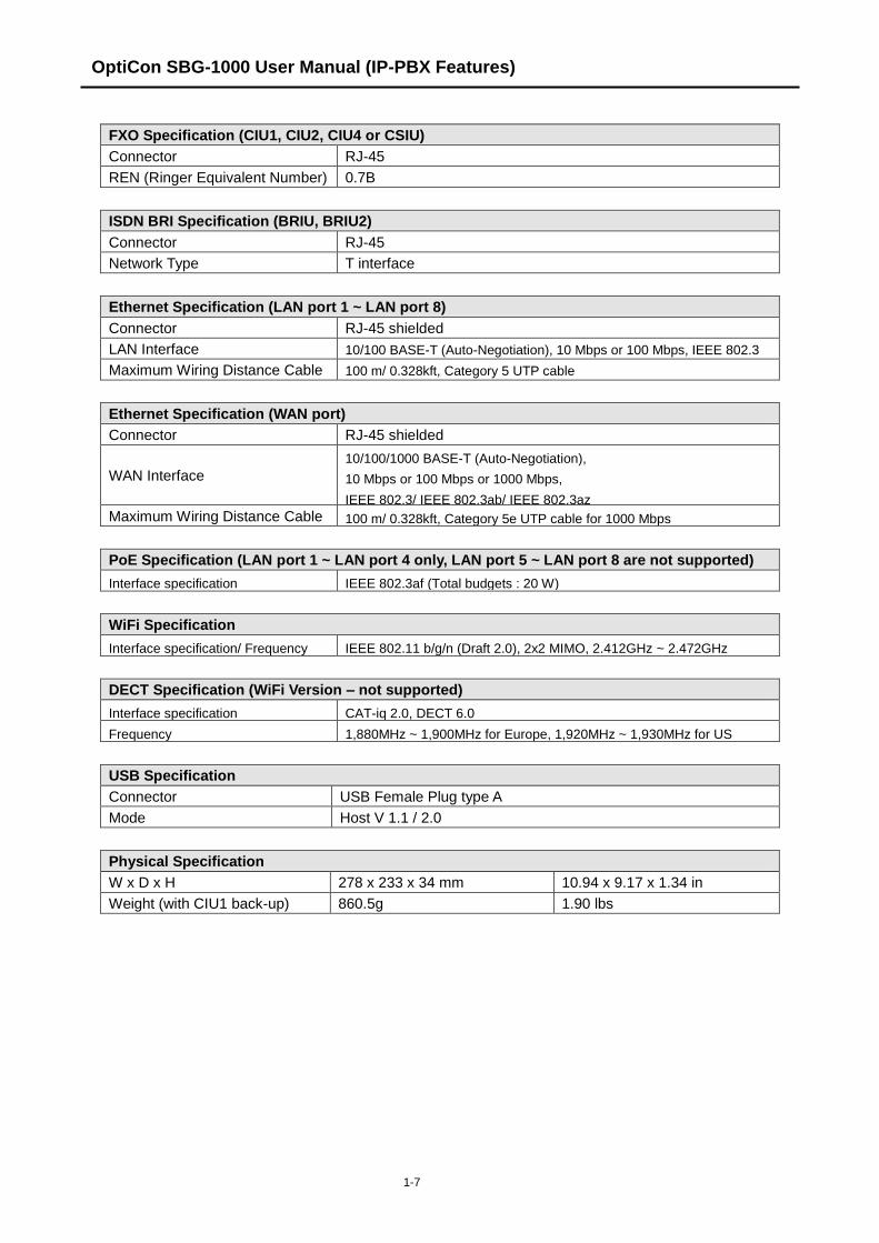
1.6 SPECIFICATIONS
Environmental Specification
Degrees (℃) Degrees (℉)
Operation Temperature 0 ~ 40 32 ~ 104
Optimum Operation Temperature 20 ~ 26 68 ~ 78
Storage Temperature 0 ~ 70 32 ~ 158
Relative Humidity 0~80% RH non-condensing
Power Adaptor Specification*
AC Input AC100-240V, 50/60Hz, 1A max.
DC Output DC48V, 0.8A max
A Power adaptor is delivered with Smart Business gateway.
FXS Specification (Basic SLT or CSIU)
Connector RJ-45
Loop Distance 1.5 Km AWG #24 (0.5mm)
Ring Capacity 60Vrms (up to 3 REN)
Ring Frequency 25Hz
OptiCon SBG-1000 User Manual (IP-PBX Features)
1-7
FXO Specification (CIU1, CIU2, CIU4 or CSIU)
Connector RJ-45
REN (Ringer Equivalent Number) 0.7B
ISDN BRI Specification (BRIU, BRIU2)
Connector RJ-45
Network Type T interface
Ethernet Specification (LAN port 1 ~ LAN port 8)
Connector RJ-45 shielded
LAN Interface 10/100 BASE-T (Auto-Negotiation), 10 Mbps or 100 Mbps, IEEE 802.3
Maximum Wiring Distance Cable 100 m/ 0.328kft, Category 5 UTP cable
Ethernet Specification (WAN port)
Connector RJ-45 shielded
WAN Interface
10/100/1000 BASE-T (Auto-Negotiation),
10 Mbps or 100 Mbps or 1000 Mbps,
IEEE 802.3/ IEEE 802.3ab/ IEEE 802.3az Maximum Wiring Distance Cable 100 m/ 0.328kft, Category 5e UTP cable for 1000 Mbps
PoE Specification (LAN port 1 ~ LAN port 4 only, LAN port 5 ~ LAN port 8 are not supported)
Interface specification IEEE 802.3af (Total budgets : 20 W)
WiFi Specification
Interface specification/ Frequency IEEE 802.11 b/g/n (Draft 2.0), 2x2 MIMO, 2.412GHz ~ 2.472GHz
DECT Specification (WiFi Version – not supported)
Interface specification CAT-iq 2.0, DECT 6.0
Frequency 1,880MHz ~ 1,900MHz for Europe, 1,920MHz ~ 1,930MHz for US
USB Specification
Connector USB Female Plug type A
Mode Host V 1.1 / 2.0
Physical Specification
W x D x H 278 x 233 x 34 mm 10.94 x 9.17 x 1.34 in
Weight (with CIU1 back-up) 860.5g 1.90 lbs

OptiCon SBG-1000 User Manual (IP-PBX Features)
2-1
2. CALL FEATURES
2.1 SYSTEM TIME
2.1.1 LCD Date/Time Format Control
Description
The Attendant can select the format of the time and date provided to the LCD of all LIP Phones in
the system.
The Attendant can select (toggle between) two formats for both time and date. The formats are:
Date: Month/day/year or Year/month/date
Time: 12 hour or 24 hour (military)
Operation
Attendant
To Change LCD Date Format (toggle):
1. Press the [PGM] button.
2. Dial „021‟ (Date Display Format program code).
To Change LCD Time Format (toggle):
1. Press the [PGM] button.
2. Dial „022‟ (Time Display Format program code).
Conditions
Programming
Related Features
Attendant Position
Hardware
2.1.2 Auto Service Mode Control
Description
The service mode defines different ring assignments and answering privileges for the system. The
service mode can be controlled automatically through definitions in the Day/Night/Timed Mode

OptiCon SBG-1000 User Manual (IP-PBX Features)
2-2
Table, which defines the time of day for the Day, Night and Timed shift modes. The Attendant may
change the system mode selection from automatic to manual.
Operation
System
Operation of this feature is automatic.
Conditions
Programming
VOICE CONFIG System Data – Day/Night/Timed Schedule
Related Features
Off-Hook Signaling
Day/Night/Timed Ring Mode
CO Ring Assignment
Hardware
2.1.3 Day/Night/Timed Ring Mode
Description
The Ring Mode is controlled automatically by the system clock. Ring assignments are applied
based on the time of day and day of week. Three modes of ring (Ring Assignments) are provided,
Day, Night and Timed.
The Attendant controls the system Ring Service mode changing from Auto Service Mode to Day,
Night or Timed service mode. Based on the service mode selected, different ring assignments,
answering privileges are invoked for system users.
Operation
Attendant
To change Day/Timed/Night Ring Mode manually;
1. Press the [DND] button.
2. Dial 1~4. (1: Day mode, 2: Night mode, 3: Timed mode, 4: Auto Service mode)
3. Press [HOLD/SAVE] button.
Conditions
1. Only Attendants can change Day/Timed/Night Ring Mode for the system manually and
program the Auto Ring Mode Selection Table.

OptiCon SBG-1000 User Manual (IP-PBX Features)
2-3
2. Stations receive incoming ring for CO lines based on database assignment and the system
mode (Day/Night/Timed) when the call arrives.
3. When the Day/Night/Timed Mode Table is programmed, the ring is changed automatically
based on the times assigned in the table.
4. The Attendant always has manual control of System mode by enabling/disabling the Auto
Service Mode Control.
Programming
VOICE CONFIG CO Line Data – Call Routing by Line
CO Line Data – Ring Assignment Table
System Data – Day/Night/Timed Schedule
Related Features
CO Ring Assignment
Hardware
2.2 CALL FORWARD
Description
Users may have selected incoming calls re-routed to other stations, station groups, the VSF, or
over a system CO line (Off-Net).
The user selects the type and condition under which calls are to be forwarded by entering a Call
Forward code as follows:
Code 0: Remote Call Forward; forwards all calls to the station, except recalls,
activated from a remote station, Call Forward, Follow-me.
Code 1: Unconditional; all calls to the station, except recalls, are forwarded
internally or externally immediately upon receipt.
Code 2: Busy; if the station is busy, forwards all calls, except recalls, to the
selected station.
Code 3: No Answer; forwards all calls, except recalls, to the selected station
when the station does not answer within the No Answer timer.
Code 4: Busy/No Answer; forwards calls if the selected station is busy or
does not answer within the No Answer timer.
Code 6: Off-Net Unconditional; all calls to the station, except recalls, are
forwarded internally or externally (SLT only).
Code 7: Off Net Busy; forwards all calls, except recalls, to the selected station
when station is busy (SLT only).

OptiCon SBG-1000 User Manual (IP-PBX Features)
2-4
Code 8: Off Net No Answer; forwards all calls, except recalls, to the selected
station when the station does not answer within the No Answer timer (SLT only).
Code 9: Off Net Busy/No Answer; forwards calls if the selected station is busy
or does not answer within the No Answer timer (SLT only).
Operation
LIP Phone
To activate Call Forward, Unconditional or Busy/No Answer:
1. Lift the handset or press the [SPEAKER] button to receive dial tone.
2. Press the [FWD] button.
3. Dial desired Call Forward code (1-4).
4. Dial the station or station group to receive calls.
5. Replace the handset, return to idle.
To activate Call Forward, Off Premise (to an external number):
1. Lift the handset or press the [SPEAKER] button to receive dial tone.
2. Press the [FWD] button.
3. Dial Forward condition (1-4)
4. Press [SPEED] button and desired bin number.
5. Replace the handset, return to idle.
To activate Call Forward, Remote (Follow-me):
1. Lift the handset or press [SPEAKER] button to receive dial-tone
2. Press the [FWD] button,
3. Dial Call Forward code „0‟,
4. Dial the station‟s Authorization Code (Station number + password),
5. Dial Forward condition (1-4),
6. Dial the destination station or station group,
7. Replace the handset, return to idle.
To deactivate Call forward:
1. Press flashing [FWD] button, Call Forward will deactivate and the [FWD] button LED is off.
SLT
To activate Call Forward, Unconditional, Busy/No Answer to an internal number:
1. Lift the handset to receive dial tone.
2. Dial 54 (Call Forward code).
3. Dial desired Call Forward code (1-4).
4. Dial station or station group to receive the calls.
5. Replace the handset, return to idle.
To activate Call Forward, to an external number:
1. Lift the handset to receive dial tone.
2. Dial 54 (Call Forward code).
3. Dial Call Forward code (6-9),

OptiCon SBG-1000 User Manual (IP-PBX Features)
2-5
4. Dial Speed Dial bin number.
5. Replace handset to return to idle.
To activate Call Forward, Remote (Follow-me):
1. Lift the handset.
2. Dial 54 (Call Forward code).
3. Dial Remote Forward code „0‟
4. Dial the station‟s Authorization Code (Station + Password),
5. Dial Forward condition (1-4)
6. Dial the destination station or station group.
7. Replace handset return to idle.
To deactivate the Call forward:
1. Lift the handset, receive stutter dial-tone,
2. Dial 54 (Call Forward code).
3. Dial „#‟ to cancel Call Forward.
Conditions
1. A station receiving a forwarded call can transfer the call to the forwarding station.
2. A forwarded intercom call will signal the receiving station in the Tone Signaling mode,
regardless of the Intercom Signaling Mode at the station.
3. Calls cannot be forwarded to a station in DND; if attempted, an error tone is returned.
4. Active Call Back or Queue requests are not canceled when attempting to activate Call
Forward.
5. When Call Forward is active, a station can make outgoing calls (internal or external) but
cannot activate a Call back or Queue request.
6. For CO calls, manually activated Call Forward will override any Preset Call Forward assigned
for the station or CO line.
7. Call Forward status is maintained in the system‟s non-volatile memory for protection from
power outage.
8. A station in a Station Hunt Group (Circular or Terminal) can be assigned to receive incoming
hunt calls, overriding any Call Forward (the system either recognizes the Forward condition
and bypasses hunt calls around the station, or routes hunt calls to the station based on the
system database; Member Forward).
9. Off-Net Call Forward of incoming CO calls is essentially an automated DISA call that will
establish an Unsupervised Conference; these calls are subject to the conditions of a DISA
call and Unsupervised Conference and may require entry of an Authorization Code.
10. Off-Net forward calls are not answered until the system completes dialing of the external call;
the call, regardless of internal or external, is then connected to the Off-Premise call.
11. An unlimited number of stations may be set-up in a Call Forward chain, forwarding calls from
one station to the next; a station cannot forward calls to a station already a part of the chain.
12. Calls to a Call Forward chain will progress as appropriate through the chain to the last
station; if the last station enters DND, CO calls revert to the previous station while intercom
calls receive a DND tone.

OptiCon SBG-1000 User Manual (IP-PBX Features)
2-6
13. No Answer forward will employ the Station No Answer Forward Timer unless it is set to zero
in which case the System No Answer Timer is used.
14. If the Attendant activates Unconditional Call Forward, the receiving station will receive
Attendant calls and recall ring; if the receiving station is an LIP Phone, the user will be able to
activate features normally reserved for a Main Attendant.
Programming
VOICE CONFIG System Data – Call Feature Timer – Call Forward No Answer Timer
Related Features
DND (Do Not Disturb)
Station Groups
Individual Speed Dial
Common Speed Dial
Intercom Answer Mode
Call Forward, Preset
Hardware
2.3 CALL FORWARD, PRESET
Description
With Preset Call Forward, calls to a station forward to a pre-determined destination assigned in the
system database. Preset Station Call Forward can define separate treatments for CO calls and
intercom calls. In addition, separate busy and no-answer treatments are defined, and calls can be
directly forward to the users Voice Mail box. Call treatments available include:
Unconditional; all calls are immediately forwarded
Internal Busy; Intercom calls encountering a busy signal are forwarded immediately
ICM No-Answer; Intercom calls not answered in the No-Answer time are forwarded (Note:
calls to a busy station are also forward after the No-Answer time)
External Busy; external calls that encounter busy are forwarded immediately
External No-Answer; external calls, not answered in the No-Answer time are forward (Note:
calls to a busy station also are forward after the No-Answer time)
Operation
System
Operation of Preset Call Forward is automatic.
Conditions
1. A station receiving a forwarded call can transfer the call to the forwarding station.
2. Calls cannot be forwarded to a station in DND; if attempted, an error tone is returned.

OptiCon SBG-1000 User Manual (IP-PBX Features)
2-7
3. Manual Forward has higher priority than Preset Forward and overrides any Preset Forward
setting.
4. Calls to a Preset Call Forward chain will progress as appropriate through the chain to the last
station. If a station in manual Call Forward or DND is encountered, it is bypassed and the
next station in the chain is signaled. If the last station has entered DND, CO calls revert to the
previous station, signaling until answered or abandoned.
5. Internal Busy or No Answer will only operate when the internal call encounters a busy state
or no answer, respectively. External Busy or External No Answer will only operate when the
external call encounters a busy state or no answer, respectively.
6. Preset call forward status is not shown in the station‟s LCD display.
7. A station in a Station Hunt Group (Circular or Terminal) can be assigned to receive incoming
hunt calls, overriding any Call Forward. That is, either the system recognizes the Forward
condition and bypasses hunt calls around the station or routes hunt calls to the station based
on the system database.
8. No Answer forward will employ the Station No Answer Forward Timer unless it is set to zero
in which case the System No Answer Timer is used.
Programming
VOICE CONFIG Station Data – Preset Call Forward
System Data – Call Feature Timer – Call Forward No Answer Timer
Related Features
Call Forward
Off-Hook Signaling
VSF Integrated Auto Attd/Voice Mail
DND (Do Not Disturb)
Hardware
2.4 CALL PARK
Description
A user may place an active CO call in a special holding location (Call Park/Park Orbit) for easy
access from any station in the system (default=601-610).
Operation
LIP Phone
To park an active external call:
1. Press the [TRANS] button.
2. Dial the Call Park/Park Orbit code (601-610).
3. Return to idle.

OptiCon SBG-1000 User Manual (IP-PBX Features)
2-8
To retrieve a parked call:
1. Lift the handset or press the [SPEAKER] button,
2. Dial the Call Park/Park Orbit code (601-610).
SLT
To park an active external call:
1. Momentarily press the hook-switch.
2. Dial the Call Park/Park Orbit code (601-610).
3. Return to idle.
To retrieve a parked call:
1. Lift the handset.
2. Dial the Call Park/Park Orbit code (601-610).
Conditions
1. If the selected Call Park/Park Orbit returns a busy signal, the user may dial another Call
Park/Park Orbit without the need to disconnect.
2. Intercom calls cannot be placed in a Call Park/Park Orbit location.
3. A Parked call will recall to the station that parked the call should the Call Park Timer expire;
the normal Hold Recall process is then initiated.
4. A Parked call will indicate busy at all appearances.
Programming
VOICE CONFIG System Data – Call Feature Timer – Call Park Recall Timer
Related Features
Hold Recall
Attendant Recall
Hardware
2.5 CALL PICK-UP
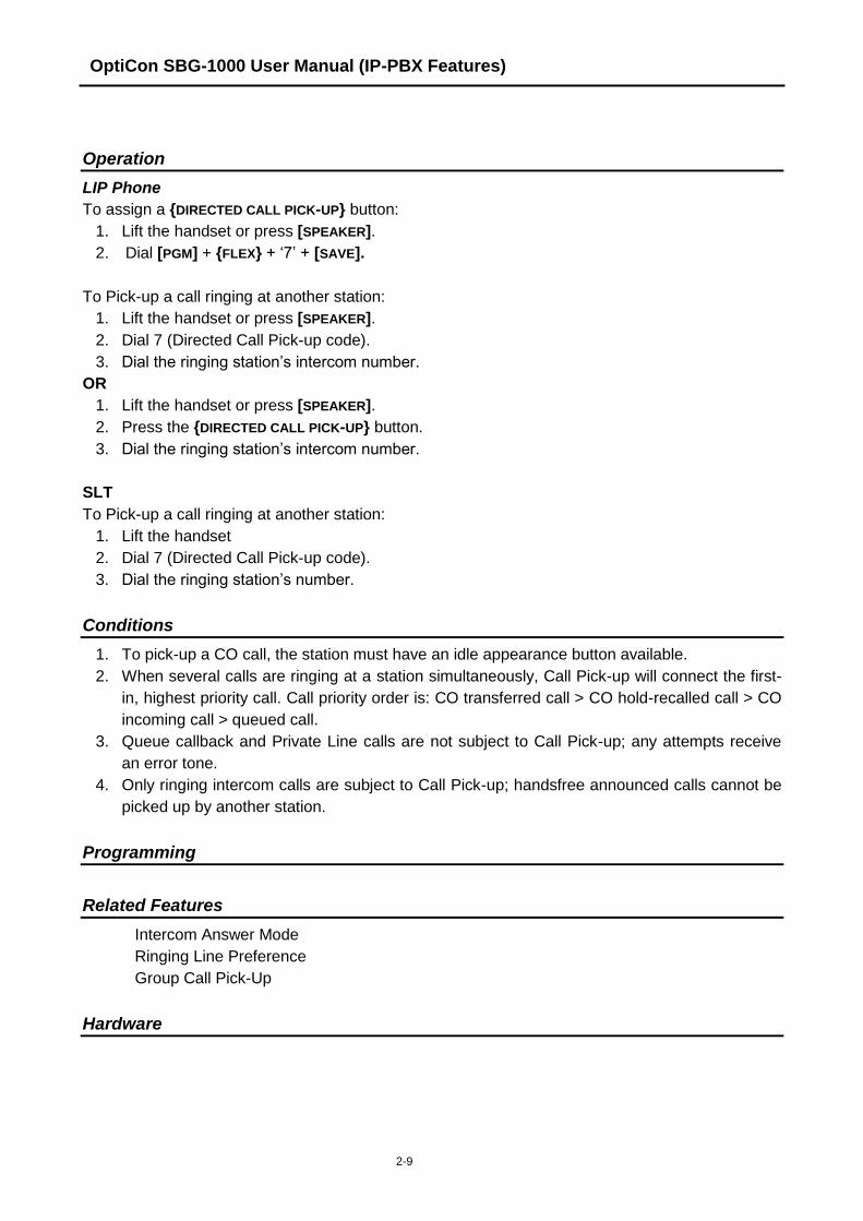
2.5.1 Directed Call Pick-Up
Description
A station may answer incoming and transferred intercom, CO and IP calls ringing at another
station (Call Pick-Up). All ringing calls are subject to Directed Call Pick-up except Queue
Callbacks.
LIP phone users may assign a Flex button as a {DIRECTED CALL PICK-UP} button.
OptiCon SBG-1000 User Manual (IP-PBX Features)
2-9
Operation
LIP Phone
To assign a {DIRECTED CALL PICK-UP} button:
1. Lift the handset or press [SPEAKER].
2. Dial [PGM] + {FLEX} + „7‟ + [SAVE].
To Pick-up a call ringing at another station:
1. Lift the handset or press [SPEAKER].
2. Dial 7 (Directed Call Pick-up code).
3. Dial the ringing station‟s intercom number.
OR
1. Lift the handset or press [SPEAKER].
2. Press the {DIRECTED CALL PICK-UP} button.
3. Dial the ringing station‟s intercom number.
SLT
To Pick-up a call ringing at another station:
1. Lift the handset
2. Dial 7 (Directed Call Pick-up code).
3. Dial the ringing station‟s number.
Conditions
1. To pick-up a CO call, the station must have an idle appearance button available.
2. When several calls are ringing at a station simultaneously, Call Pick-up will connect the first-
in, highest priority call. Call priority order is: CO transferred call > CO hold-recalled call > CO
incoming call > queued call.
3. Queue callback and Private Line calls are not subject to Call Pick-up; any attempts receive
an error tone.
4. Only ringing intercom calls are subject to Call Pick-up; handsfree announced calls cannot be
picked up by another station.
Programming
Related Features
Intercom Answer Mode
Ringing Line Preference
Group Call Pick-Up
Hardware

OptiCon SBG-1000 User Manual (IP-PBX Features)
2-10
2.5.2 Group Call Pick-Up
Description
A station can answer (Call Pick-Up) incoming and transferred intercom, CO and IP calls ringing at
another station. All ringing calls, except Private Line and Queue Callbacks, are subject to Pick-up
by other stations in the same group.
LIP phone users may assign a Flex button as a {GROUP CALL PICK-UP} button.
Operation
LIP Phone
To assign a {GROUP CALL PICK-UP} button:
1. Lift the handset, press [PGM] + {FLEX} + „**‟ + [SAVE].
To Pick-up a call ringing at another station:
1. Lift the handset or press [SPEAKER].
2. Dial „** (Group Call Pick-up code).
OR, 2. Press the {GROUP CALL PICK-UP} button.
SLT
To Pick-up a call ringing at another station:
1. Lift the handset.
2. Dial „** (Group Call Pick-up code).
Conditions
1. To pick-up a CO call, the station must have an idle appearance button available.
2. When several calls are ringing simultaneously, Call Pick-up will connect the first-in, highest
priority call. Call priority order is: CO transferred call > CO hold-recalled call > CO incoming
call > queued call.
3. Queue callback calls are not subject to Call Pick-up; any attempt will receive an error tone.
4. Only ringing intercom calls are subject to Call Pick-up; handsfree announced calls can not be
picked up by another station
5. When a station belongs to multiple groups, calls to the station group with lowest sequential
group number are answered first. For example, if an incoming call is ringing at both Station
Groups 620 and 621; when Station 100 (member to both Station Groups) responds to the
ringing and picks up, the call to Station Group 620 will be answered first (by default).
Programming
VOICE CONFIG Station Group Data
Related Features
Intercom Answer Mode
Directed Call Pick-Up
Station Groups

OptiCon SBG-1000 User Manual (IP-PBX Features)
2-11
Hardware
2.6 CALL TRANSFER
2.6.1 Call Transfer, Station
Description
CO calls can be transferred to other stations in the Smart Business gateway (OptiCon SBG-1000)
system. Calls can be transferred announcing the call (screened) or without an announcement
(unscreened).
When a CO call is transferred, the Transfer Recall Timer is initiated. If the timer expires before the
call is answered, the Hold Recall process is initiated.
Users can transfer an active Intercom call to other stations in the OptiCon SBG-1000 system,
using either screened or unscreened transfer. When used, the Intercom station is placed on
Exclusive Hold, and the Transfer Recall timer is initiated. if the timer expires before the Intercom
call is answered, the call will bounce back (recall) to the transferring station until answered or
abandoned.
Operation
LIP Phone
While on a CO call, to perform a Screened Call Transfer:
1. Press [TRANS].
2. Dial the station to receive the transfer.
3. At answer or splash tone announce the call.
4. Hang-up to complete the transfer.
OR
1. Press the {DSS/BLF} button for the desired station.
2. At answer or splash tone, announce the call.
3. Hang-up to complete the transfer.
While on a CO call, to perform an Unscreened Call Transfer:
1. Press [TRANS].
2. Dial the station to receive the transfer.
3. Hang-up to complete the transfer.
OR
1. Press the {DSS/BLF} button for the desired station.
2. Hang-up to complete the transfer.
To perform an Screened Transfer while on an ICM call:
1. Press [TRANS] button.
2. Dial Station to receive call.
3. At answer or Splash tone, announce call.
4. Hang-up to return to idle.
OR

OptiCon SBG-1000 User Manual (IP-PBX Features)
2-12
1. Press {DSS/BLF} button for the desired station.
2. At answer or Splash tone, announce call.
3. Hang-up to return to idle.
To perform an Unscreened Transfer while on an ICM call:
1. Press [TRANS] button.
2. Dial Station to receive call.
3. Hang-up to return to idle.
OR
1. Press {DSS/BLF} button for the desired station.
2. Hang-up to return to idle.
SLT
While on a CO call, to perform a Screened Call Transfer:
1. Momentarily depress the hook-switch.
2. Dial the station to receive the transfer.
3. At answer or splash tone announce the call.
4. Hang-up to complete the transfer.
While on a CO call, to perform an Unscreened Call Transfer:
1. Momentarily depress the hook-switch.
2. Dial the station to receive the transfer.
3. Hang-up to complete the transfer.
To perform a Screened transfer of an active Intercom call:
1. Momentarily depress the Hook-switch.
2. Dial Station to receive call.
3. At answer or Splash tone, announce call.
4. Hang-up to return to idle.
While on an Intercom call, Unscreened call transfer:
1. Momentarily depress the Hook-switch.
2. Dial Station to receive call.
3. Hang-up to return to idle.
Conditions
1. The transferring station may camp a call at a busy station (refer to Camp-On).
2. The LED of a {LOOP} button will display the status of a call until the station no longer has call
supervision (ex., the call is successfully transferred).
3. To prevent Toll abuse, CO lines without an active call (either incoming or dialed digits on
outgoing) cannot be transferred.
4. For outgoing CO Line calls, the system will monitor the CO Line for dial-tone to prevent Toll
abuse; when an IP Line is seized, the system does not monitor for dial-tone.
5. While on intercom call transfer, the [ICM] button provides an appearance for the transferred
station; LED indicates status and pressing the button connects to the station.
OptiCon SBG-1000 User Manual (IP-PBX Features)
2-13
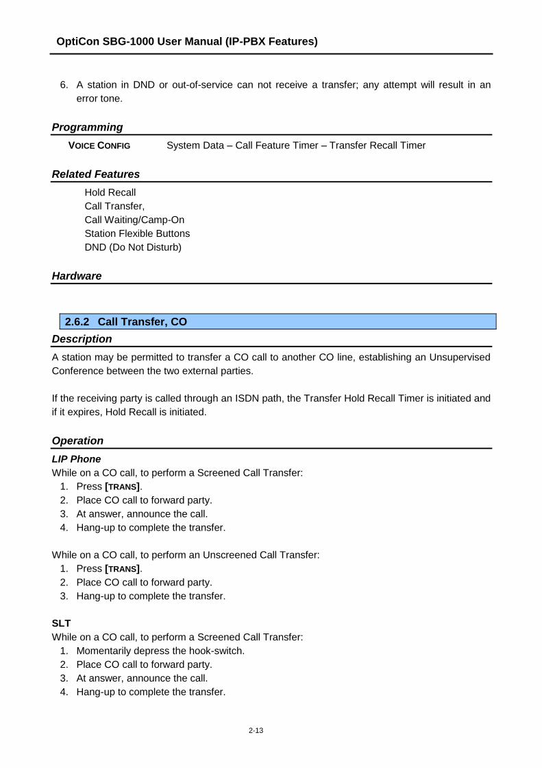
6. A station in DND or out-of-service can not receive a transfer; any attempt will result in an
error tone.
Programming
VOICE CONFIG System Data – Call Feature Timer – Transfer Recall Timer
Related Features
Hold Recall
Call Transfer,
Call Waiting/Camp-On
Station Flexible Buttons
DND (Do Not Disturb)
Hardware
2.6.2 Call Transfer, CO
Description
A station may be permitted to transfer a CO call to another CO line, establishing an Unsupervised
Conference between the two external parties.
If the receiving party is called through an ISDN path, the Transfer Hold Recall Timer is initiated and
if it expires, Hold Recall is initiated.
Operation
LIP Phone
While on a CO call, to perform a Screened Call Transfer:
1. Press [TRANS].
2. Place CO call to forward party.
3. At answer, announce the call.
4. Hang-up to complete the transfer.
While on a CO call, to perform an Unscreened Call Transfer:
1. Press [TRANS].
2. Place CO call to forward party.
3. Hang-up to complete the transfer.
SLT
While on a CO call, to perform a Screened Call Transfer:
1. Momentarily depress the hook-switch.
2. Place CO call to forward party.
3. At answer, announce the call.
4. Hang-up to complete the transfer.

OptiCon SBG-1000 User Manual (IP-PBX Features)
2-14
While on a CO call, to perform an Unscreened Call Transfer:
1. Momentarily depress the hook-switch.
2. Place CO call to forward party.
3. Hang-up to complete the transfer.
Conditions
1. For this feature, at least one of the two CO lines (transferred or receiving) must provide
detection of disconnect supervision and lost loop condition.
2. If during transfer to an external party, the user presses the CO line of the original call, the
outgoing call is disconnected and the original call is connected to the user.
Programming
VOICE CONFIG Station Data – Authorization Code & COS – Offnet FWD
System Data – Call Feature Timer – Transfer Recall Timer
Related Features
Hold Recall
Call Transfer, Station
Hardware
2.6.3 Call Transfer, Voice Mail
Description
CO calls can be directly transferred to a station‟s VSF voice mail-box.
Operation
LIP Phone
While on a CO call, to perform a Call Transfer:
1. Press [TRANS].
2. Press [MSG/CALLBK] button.
3. Dial the number or press the {DSS/BLF} button for the desired station.
4. Hang-up to complete the transfer.
Conditions
1. The LED of a {LOOP} button will display the status of a call until the station no longer has call
supervision (ex., the call is successfully transferred).
Programming
VOICE CONFIG Station Data – Preset Call Forward
System Data – Call Feature Timer – Transfer Recall Timer

OptiCon SBG-1000 User Manual (IP-PBX Features)
2-15
Related Features
Hold Recall
Call Waiting/Camp-On
VSF Voice Mail
Hardware
LIP Phone
2.7 CALL WAITING/CAMP-ON
Description
Call Waiting is used to notify a busy station that a call is waiting. The busy station is notified of the
waiting call with a Camp-On tone. For users of an LIP Phone, the LED of the [HOLD] button will
flash.
After receiving a busy signal, the calling station camps on to the called station. The called station
can respond by:
answering the waiting call, which places the active call on hold,
activating One-Time DND, or
ignoring the Camp-On tone.
Operation
To activate a Camp-On while receiving the Intercom busy tone:
1. Press the „*‟ button, called and calling stations receive Camp-On tone.
Conditions
1. The user may only Camp-On to a station in busy mode; a user may not Camp-On to a station
in DND, a conference, receiving a Page, etc.
2. The Camp-On procedure can be employed by an Attendant to activate DND Override.
3. If the calling station disconnects from the call after activating Camp-On, Camp-On is
cancelled.
4. A Camp-On tone is sent each time the calling user presses the „*‟ button.
Programming
Related Features
DND (Do Not Disturb)
Intercom Call (ICM Call)
Voice Over
Hardware
OptiCon SBG-1000 User Manual (IP-PBX Features)
2-16
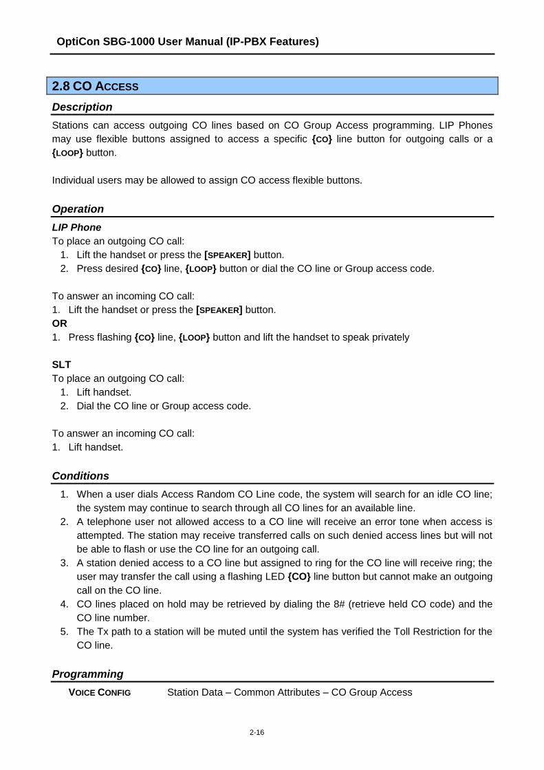
2.8 CO ACCESS
Description
Stations can access outgoing CO lines based on CO Group Access programming. LIP Phones
may use flexible buttons assigned to access a specific {CO} line button for outgoing calls or a
{LOOP} button.
Individual users may be allowed to assign CO access flexible buttons.
Operation
LIP Phone
To place an outgoing CO call:
1. Lift the handset or press the [SPEAKER] button.
2. Press desired {CO} line, {LOOP} button or dial the CO line or Group access code.
To answer an incoming CO call:
1. Lift the handset or press the [SPEAKER] button.
OR
1. Press flashing {CO} line, {LOOP} button and lift the handset to speak privately
SLT
To place an outgoing CO call:
1. Lift handset.
2. Dial the CO line or Group access code.
To answer an incoming CO call:
1. Lift handset.
Conditions
1. When a user dials Access Random CO Line code, the system will search for an idle CO line;
the system may continue to search through all CO lines for an available line.
2. A telephone user not allowed access to a CO line will receive an error tone when access is
attempted. The station may receive transferred calls on such denied access lines but will not
be able to flash or use the CO line for an outgoing call.
3. A station denied access to a CO line but assigned to ring for the CO line will receive ring; the
user may transfer the call using a flashing LED {CO} line button but cannot make an outgoing
call on the CO line.
4. CO lines placed on hold may be retrieved by dialing the 8# (retrieve held CO code) and the
CO line number.
5. The Tx path to a station will be muted until the system has verified the Toll Restriction for the
CO line.
Programming
VOICE CONFIG Station Data – Common Attributes – CO Group Access
OptiCon SBG-1000 User Manual (IP-PBX Features)
2-17
CO Line Data – Call Routing by Line
CO Line Data – Call Routing by Caller Number
CO Line Data – Ring Assignment Table
Related Features
CO Ring Assignment
Hardware
2.9 CO QUEUING
Description
When CO lines are busy, permitted users can request to be placed in queue awaiting the CO line,
or a CO line in the same group to become available. When an appropriate CO line becomes
available, the system calls the waiting station on a first-in, first-out basis.
Operation
LIP Phone
To request to be placed in queue for a busy CO line:
1. Press busy {CO} or {CO GRP} button.
2. Press the [MSG/CALLBK] button; confirmation tone is received.
3. Hang-up, the [MSG/CALLBK] LED flashes.
To cancel the queue from the queued station:
1. Press the [MSG/CALLBK] button, the [MSG/CALLBK] LED extinguishes.
SLT
To request to be placed in queue while receiving an All Lines Busy signal:
1. Momentarily press the hook-switch.
2. Dial 56 (Callback feature code).
To cancel the queue from the queued station:
1. Lift the handset.
2. Dial 56 (Callback feature code).
System
When a CO line becomes available:
1. The System will send a distinctive Queue recall to the station that was first-in queue, the
appropriate {CO} LED button will flash
2. The CO line and station will appear busy to all other users.

OptiCon SBG-1000 User Manual (IP-PBX Features)
2-18
Conditions
1. A CO line can have any number of simultaneous queue requests.
2. A station may only have a single active CO queue request; activating a new queue request
will replace, and cancel an existing queue.
3. A Queue recall will always signal the station with a tone ring, ignoring the station‟s assigned
Intercom Signaling mode.
4. Queue recall will bypass a busy station, and place the station at the bottom of the queue list.
5. Queue recall will signal a station for 15 seconds, after which, the station is removed from the
queue (the queue is cancelled).
Programming
Related Features
CO Access
Hardware
2.10 THREE-PARTY VOICE CONFERENCE
Description
The system will allow three internal and external parties to be connected on a call, conference. An
unlimited number of 3-party conferences may be established.
Operation
LIP Phone
To establish an ad-hoc conference:
1. Establish first call.
2. Press the [CONF] button; the LED will light, and the connected party is placed on exclusive
hold (the user receives dial-tone).
3. Place second call.
4. When connected, press [CONF]; the new call is placed on exclusive hold.
5. Press [CONF] button to establish 3-party conference.
To place a conference on hold:
1. Press the [HOLD] button; the [CONF] button LED will flash.
To retrieve held conference:
1. Lift the handset
2. Press [CONF] button; all parties will be reconnected.

OptiCon SBG-1000 User Manual (IP-PBX Features)
2-19
Conditions
1. The [CONF] button remains illuminated at the initiators phone for the duration of the
conference.
2. There is no limit on the number of 3-way conferences the system will support.
3. If the system receives a disconnect signal and no internal parties remain in the conference,
the conference is terminated and all parties are disconnected. If an internal party is still
connected when a disconnect signal is received, the connection to remaining parties is
maintained.
4. The normal Hold Recall process is applied to a conference on hold using the Unsupervised
Conference recall Timer for recall timing.
5. If while setting up a conference, system error tone is received, the initiator must press the
[CONF] button to obtain the Intercom dial-tone.
6. A station that is busy, in DND or other non-idle state, cannot be added to a conference.
7. SLT can join a conference call, but can not make a conference call
Programming
Related Features
Automatic Speaker Select
Hold Recall
Hardware
2.11 CUSTOMER SITE NAME
Description
A Customer Name, up to 24 characters, may be entered into the system database. The name is
displayed on the SMDR and database outputs as well as during an Admin session.
Operation
System
Operation of this feature is automatic when a name is assigned.
Conditions
Programming
VOICE INSTALL System – Identification – Site Name
SYSTEM ID Customer Site Name (PGM 100-Btn 2)
Related Features
Hardware

OptiCon SBG-1000 User Manual (IP-PBX Features)
2-20
2.12 FAX
Description
Data transmitted over CO lines is subject to distortion and errors if system tones (ex., Camp-On,
Override) are applied during transmission. To eliminate such errors, stations that use analog data
(modems or Fax) can be assigned to block incoming system tones.
Operation
System
System tones are automatically blocked when FAX utilization is set to “ON”.
Conditions
1. Stations or an Attendant attempting to Camp-On or Override a station with FAX utilization will
receive an error tone.
2. When FAX utilization is enabled, the system will not apply audio gain to the call.
Programming
VOICE INSTALL FAX – FAX Configuration – FAX Utilization
Related Features
Call Waiting/Camp-On
Hardware
2.13 DELAYED CO RING
Description
Ring signals for an incoming CO call can be sent to stations immediately upon detection or after an
assigned ring cycle delay. The delay can be up to 9 system ring cycles, thus allowing other
stations to answer the call.
Operation
System
Delay Ring operation is automatic when assigned:
Conditions
1. Delay Ring can be assigned for a station.
2. If no delay is entered when programming Ring assignments, the station will immediately ring
when a call is received.
3. Private Lines may be assigned with delayed ring.

OptiCon SBG-1000 User Manual (IP-PBX Features)
2-21
Programming
VOICE CONFIG CO Line Data – Call Routing by Line
CO Line Data – Ring Assignment Table
Related Features
CO Ring Assignment
Hardware
2.14 DELAYED AUTO ATTENDANT
Description
An incoming CO call can be routed to the VSF Auto Attendant either immediately upon detection or
after a delay of up to 30 seconds. This allows other stations assigned immediate ring the
opportunity to answer before the call is routed to the Auto Attendant.
Operation
System
Operation of this feature is automatic when assigned.
Conditions
1. When Delayed Auto Attendant Ring is assigned, after the delay, the call will no longer ring
assigned stations and will only ring to the VSF Auto Attendant.
2. If no delay is entered, the call immediately will ring to the VSF Auto Attendant.
3. To assign Delayed Attendant ring, at least one station or Station Group must be assigned for
immediate ring.
4. Ring is assigned to a VSF Auto Attendant announcement (01-70) as a “station type” with a
delay from 00 to 30 seconds.
Programming
VOICE CONFIG CO Line Data – Call Routing by Line
CO Line Data – Ring Assignment Table
Related Features
CO Ring Assignment
Hardware

OptiCon SBG-1000 User Manual (IP-PBX Features)
2-22
2.15 DIAGNOSTIC/MAINTENANCE
Description
The system software incorporates various diagnostic and maintenance routines that may be
“called” remotely or locally through the systems RS-232 serial ports, a TCP/IP connection using a
Web browser or telnet terminal established over IP networks. Routines that can be accessed
include trace functions at the device level, commands for diagnostics and maintenance, and tools
for manipulation at the OS level.
Operation
Conditions
Programming
Related Features
Hardware
2.16 DIAL-BY-NAME
Description
A name, up to 16 characters, may be assigned to each Individual and Common Speed Dial. In
addition, each station may be assigned a 12-character name. When assigned, a user may place
an intercom call to another station or select a Station or Common Speed Dial using the name.
The user selects from one of three Dial-by-Name directories and enters characters employing 2
dial pad buttons for each character (refer to Character Entry Chart Table). The system finds and
displays the nearest match to the user entries. The user may continue entering characters or scroll
the directory at any point using the [VOL▲]/[VOL▼] button and select a name to call. The number
associated with a selected name may be displayed by using the [TRANS] button.
Operation
LIP Phone
To use Dial by Name:
1. Press soft key [DIR].
2. Dial the desired directory.
3. Search the directory using the [VOL▲]/[VOL▼] button or by entering the number .

OptiCon SBG-1000 User Manual (IP-PBX Features)
2-23
Table 2.16.1 Character Entry Chart
Q – 11
Z – 12
. – 13
1 – 10
A - 21
B - 22
C - 23
2 - 20
D - 31
E - 32
F - 33
3 - 30
G – 41
H - 42
I - 43
4 - 40
J - 51
K - 52
L - 53
5 - 50
M - 61
N - 62
O - 63
6 - 60
P - 71
R - 72
S - 73
Q - 7*
7 - 70
T - 81
U - 82
V - 83
8 - 80
W - 91
X - 92
Y - 93
Z - 9#
9 - 90
Blank - *1
: - *2
, - *3
0-00 #
4. Press the [SAVE] button to place the call.
To toggle between the name and number display:
1. Press the [NAME/TEL] soft button or [TRANS/PGM] button.
To program the station user name:
1. Press the [PGM] button.
2. Dial 34 (User Name Program code).
3. Dial the name, up to 12 characters.
4. Press [SAVE].
Attendant
To program a name for another station:
1. Press the [PGM] button.
2. Dial 031 (Attendant User Name Program code).
3. Dial the station number.
4. Dial the name, up to 12 characters.
5. Press [SAVE].
Conditions
1. Available characters are A to Z, space and period.
2. The LCD will display multiple names (one per LCD line, up to 16 characters).
3. If a user selects a directory with no entries or there is no match to the user entry, error tone is
provided.
4. Dial-by-Name is only available to LIP Phones with a display; other users will receive error
tone if an attempt is made to access Dial-by-Name.

OptiCon SBG-1000 User Manual (IP-PBX Features)
2-24
5. A user may both scroll and enter characters to search a directory using the [VOL▲]/[VOL▼]
buttons.
Programming
Related Features
Individual Speed Dial
Common Speed Dial
Hardware
LIP Phone w/Display
2.17 DND (DO NOT DISTURB)
Description
A station can be placed in DND to block incoming CO and Intercom calls, transfers and paging
announcements.
Operation
LIP Phone
To activate DND:
1. Press the [DND] button; the [DND] button LED illuminates.
To remove DND:
1. Press the [DND] button; the [DND] button LED extinguishes.
SLT
To activate DND:
1. Dial 53 (DND feature code); confirmation tone is received.
To remove DND:
1. Dial 53 (DND feature code), confirmation tone is received.
Conditions
1. Pressing the [DND] button while ringing will activate One-Time DND.
2. An Attendant may cancel DND for other stations.
3. DND service is not available to Attendants.
4. Recalls for CO calls will override the DND feature.
5. A station in DND is out-of-service for all incoming calls including Station Group calls.
6. A station in DND is bypassed by calls forwarded to the station; if the last station in a Call
Forward chain is in DND, the call will ring to the previous station in the chain.
7. When calling a station in DND, the LIP Phone display will indicate the DND status.

OptiCon SBG-1000 User Manual (IP-PBX Features)
2-25
Programming
Related Features
Feature Cancel
Call Forward
Station Groups
Hardware
2.18 EMERGENCY CALL
Description
Regardless of a station‟s CO accessibility, the user may dial assigned Emergency numbers.
Operation
System
The system will automatically override any toll restrictions and process an assigned Emergency
number.
Conditions
1. If there is no idle CO line for emergency call, one of busy CO line will be forced to release the
current call and used for emergency call.
2. Emergency call can be placed without any CO access code, except Australia. But if
emergency call is same as station number or starts with station number, then emergency call
cannot be used without CO access code. For example, if emergency code is “112” and
station number “112” is used, user should dial CO access code first in order to make
emergency call. Otherwise station “112” receives a ring.
Programming
VOICE CONFIG System Data – Emergency Dialing
Related Features
Hardware
OptiCon SBG-1000 User Manual (IP-PBX Features)
2-26
2.19 FLEXIBLE NUMBERING PLAN
Description
User access to the OptiCon SBG-1000 system resources and features is accomplished through
feature codes or LIP Phone buttons. The Administrator, if desired, assigns codes for individual
functions in the Flexible Numbering Plan. The feature codes are defined in the system‟s Flexible
Numbering Plan.
Operation
System
System implements feature activation based on the Flexible Numbering Plan.
Conditions
1. Feature codes can be 1-3 digits in length.
2. During programming, conflicts in the Numbering Plan are not allowed; the existing non-
conflicting Numbering Plan is used until correctly updated.
Programming
VOICE INSTALL Numbering Plan
Related Features
Hardware
2.20 HEADSET COMPATIBILITY
Description
An industry standard headset can be connected to an LIP Phone in place of or in addition to the
handset. The station is then programmed for Headset operation.
In the Headset mode, pressing the [SPEAKER] button will send audio to the Headset instead of the
speakerphone. In addition, when in the Headset mode, ring signals can be delivered to the
speaker or the headset as defined in the system database.
Operation
LIP Phone
To change operation from Speakerphone to Headset:
1. Press the [PGM] button.
2. Dial 12 (Headset select code).
3. Dial „0‟ to select Headset, „1‟ to select Speakerphone.
OR,
1. Press [HEADSET] button.
OptiCon SBG-1000 User Manual (IP-PBX Features)
2-27
2. Dial „0‟ to select Headset, „1‟ to select Speakerphone.
To change the device to receive ring signals:
1. Press the [PGM] button.
2. Dial 13 (Ring select code).
3. Dial „1‟ for Speaker, „2‟ for Headset or „3‟ for both.
To place/answer calls using the headset:
1. Press the [SPEAKER] with the phone in Headset mode.
Conditions
1. The Intercom Signaling Mode can be set in the Headset mode as with the Speakerphone
mode.
2. The station always receives Page announcements over the speaker of the LIP Phone.
3. Although the phone is in the headset mode, the system will monitor the hook-switch status. If
a user lifts the handset to go off-hook, audio is delivered to the handset.
Programming
VOICE CONFIG Station Data – Common Attributes – Headset Ring
Station Data – Common Attributes – Headset or Speaker Mode
Related Features
Speakerphone
Paging
Hardware
2.21 HOLD
2.21.1 Hold
Description
CO lines may be placed in a waiting state such that other stations in the system are able to access
the CO line. Stations must have System database access to the CO line to access the held call.
If the call remains on hold at expiration of the System Hold Recall Timer, normal Hold Recall will
be activated.
Operation
LIP Phone
To place a call on System Hold:
1. Press the [HOLD] button.

OptiCon SBG-1000 User Manual (IP-PBX Features)
2-28
To access a call from System Hold:
1. Lift the handset or press the [SPEAKER] button.
2. Press the {CO} line button.
OR
1. Lift the handset or press the [SPEAKER] button.
2. Dial 8# (Held CO Call Access code).
3. Dial the CO line number
SLT
To place a call on System Hold:
1. Momentarily press the hook-switch.
2. Dial 67 (System Hold feature code).
To access a call from System Hold:
1. Lift the handset.
2. Dial 8# (Held CO Call Access code).
3. Dial the CO line number.
Conditions
1. When a CO line is placed on System Hold, the button LED will flash at 30 ipm (it will wink at
the holding station and will flash at all other stations).
2. A call on System Hold can be retrieved from any station allowed access to the CO line in the
system database using the CO line button or the Held CO call access code.
3. The LED of {LOOP} buttons will display the CO line status.
Programming
VOICE CONFIG System Data – Call Feature Timer – Attendant Recall Timer
System Data – Call Feature Timer – System Hold Recall Timer
Related Features
Call Transfer,
Hold Recall
Hardware
2.21.2 Hold Recall
Description
When a user places a CO call on hold, a hold timer is activated. If the timer expires, the held call
will recall at the station for the I-Hold Recall time. If the call remains unanswered, the call is placed
on System Hold and the Attendant also receives a recall for the Attendant Recall time. If still
unanswered after the Attendant Recall time, the CO call is disconnected and the appropriate
circuits are returned to idle.

OptiCon SBG-1000 User Manual (IP-PBX Features)
2-29
Operation
Hold Recall operation is automatic.
Conditions
1. Separate timers are assigned for the various types of hold: System, Transfer, etc.
2. If the I-Hold timer is set to zero, the station will not receive a recall; if the Attendant Recall
timer is set to zero, the also Attendant will not receive a recall.
3. If the specific Hold timer is set to zero, recall is disabled.
Programming
VOICE CONFIG System Data – Call Feature Timer – Attendant Recall Timer
System Data – Call Feature Timer – System Hold Recall Timer
System Data – Call Feature Timer – Transfer Recall Timer
Related Features
Call Transfer,
Hold
Hardware
2.21.3 Automatic Hold
Description
While on an active CO call, the system will place the call on hold automatically if the user presses
the [FLASH], [CONF], {DSS/BLF} or other feature buttons. In addition, the station can be programmed
to support CO to CO Automatic Hold. In this case, pressing a CO button while on a CO call will
place the active call on hold and access the selected CO line.
Operation
LIP Phone
To use Automatic Hold while on an active CO call:
1. Press the desired feature button or {CO}; the active call is placed on Hold.
Conditions
1. There is no limit on the number of calls that can be placed on Hold using Automatic Hold.
Programming
Related Features
Hold Recall

OptiCon SBG-1000 User Manual (IP-PBX Features)
2-30
Hardware
LIP Phone
2.22 CALL ROUTING BY CALLER NUMBER
Description
The system can employ caller number to determine the routing of incoming external calls. Each
CO Line may be assigned to employ call routing by caller number. The system will compare the
received caller number to entries in the Call Routing by Caller Number Table, and if a match is
found, will route the call to the destination defined in the Ring Assignment Table. Destinations can
be the VSF, a station or a station group.
Operation
System
System implements routing automatically based on database entries and the received caller
number.
Conditions
1. For analog CO Lines, the system will await receipt of valid ICLID for the ICLID Ring Timer. At
expiration of the timer, if ICLID is not received, the call is routed based on the type and other
programming (Ring assignments, etc.).
2. If the received caller number does not match an entry in the Call Routing by Caller Number
Table, the call is routed based on the type and other programming (Ring assignments, etc.)
for CO Line.
3. The caller number received from the CO Line may be a telephone number or name that must
match an Call Routing by Caller Number Table entry.
Programming
VOICE CONFIG CO Line Data – Call Routing by Line
CO Line Data – Call Routing by Caller Number
CO Line Data – Ring Assignment Table
Related Features
CO Ring Assignment
Hardware

OptiCon SBG-1000 User Manual (IP-PBX Features)
2-31
2.23 IP FAX RELAY, T.38 SUPPORT
Because of their nature, Fax tones do not transmit well through IP networks, particularly when
compression is employed. To address this, OptiCon SBG-1000 supports the T.38 protocol that
defines the translation of fax tones to digital signals. When Fax tone is detected on a port of an
OptiCon SBG-1000, the system will activate a T.38 Fax relay channel to the appropriate Line or
SLT module.
Operation
Operation of this feature is automatic.
Conditions
Programming
VOICE INSTALL FAX – FAX – T.38
Related Features
Hardware
2.24 LNR (LAST NUMBER REDIAL)
Description
The last number dialed is stored (up to 23 digits) in the station‟s Last Number Redial buffer. The
user may request the system redial the last dialed number without the need to dial the number.
For LIP Phones with displays, the last 15 numbers are stored in the LNR buffer. The user may
view the numbers using the [VOL▲]/[VOL▼] button and select the number to dial from the list.
Operation
LIP Phone
To assign a Flex button as an {redial} button:
1. Press [PGM] + {FLEX} + [PGM] + „54‟ + [SAVE]
To use Last Number Redial:
1. Lift the handset or press the [SPEAKER] button.
2. Press the {REDIAL} button.
3. Press the [VOL▲]/[VOL▼] button to highlight the desired number.
4. Press [SAVE] or {REDIAL} to dial the number highlighted.
SLT
To use Last Number Redial:
1. Lift the handset.

OptiCon SBG-1000 User Manual (IP-PBX Features)
2-32
2. Dial „52‟, the Last Number Redial code.
Conditions
1. For LIP Phones with display, the redial buffer will store duplicate numbers unless dialed
consecutively.
2. When the CO line used for the original call is busy, the system will select an idle line from the
same CO line Group to place the call.
3. Using Last Number Redial will cancel Automatic Called Number Redial if active.
4. The LNR buffer is not stored in non-volatile memory and will be erased if power to the system
is lost.
5. Manually dialing a Flash during an outgoing call will cause only those digits dialed after the
Flash to be stored in the LNR buffer.
Programming
Related Features
Save Number Redial (SNR)
Individual Speed Dial
Common Speed Dial
Hardware
2.25 MOH (MUSIC-ON-HOLD)
Description
When a call is placed on hold, the system will deliver audio from the defined MOH source. In this
way, the connected user can determine that the connection is still active.
A message or music recorded in the VSF can be employed as MOH. The Attendant records the
VSF announcement for MOH and VSF MOH is assigned as the MOH source.
Operation
System
Operation of MOH is automatic.
Attendant
To record a VSF announcement for MOH: 1. Press the [PGM] button.
2. Dial 05 (VSF Record code).
3. Dial 071 (VSF MOH Announcement number).
4. The current announcement is played followed by the “Press # to record” prompt.
5. Dial „#‟.
6. After the record prompt and beep-tone, record message. 7. Press the [SAVE] button to stop recording and save the message.

OptiCon SBG-1000 User Manual (IP-PBX Features)
2-33
Conditions
1. Only VSF announcement number 71 may be used for the MOH message.
Programming
VOICE CONFIG Station Data – Station Hold Music
CO Line Data – CO Hold Music
Related Features
Hold
Hardware
2.26 REGISTRATION & REGISTRATION TABLE
Description
To eliminate the potential for unintended device registration, the system can be programmed to
allow local device registration employing MAC addresses. Using the defined MAC address
registration, the system allows devices with matching MAC addresses to register.
The Registration Table permits entry of up to 12 MAC addresses to be registered for the device;
entering the MAC address permits the device to register with the system. If the device which has
the matching MAC address is successfully registered, the MAC address is removed from the
Registration Table.
Operation
Operation of registration is automatic based on the system database.
Conditions
Programming
VOICE INSTALL Station Registration – Registration Table
Related Features
Hardware

OptiCon SBG-1000 User Manual (IP-PBX Features)
2-34
2.27 RINGING LINE PREFERENCE
Description
A station is automatically connected to incoming calls by lifting the handset or pressing the
[SPEAKER] button when assigned Ringing Line Preference (RLP).
Operation
LIP Phone
To answer a call while the station is ringing:
1. Lift the handset or press the [SPEAKER] button.
Conditions
1. When multiple calls are ringing at the station, a priority defines the order in which calls are
answered. The priority is:
Transfer > recalls > incoming calls > queued calls
2. Intercom calls are always given the lowest answering priority.
3. SLTs operate only in the RLP mode; when ringing, lifting the handset connects the SLT to the
ringing call.
Programming
Related Features
Automatic Speaker Select
Hardware
2.28 SPEED DIAL
2.28.1 Display Security
Description
Individual and Common Speed Dial numbers may be programmed so that the digits are not
displayed on the LCD of LIP phones.
Operation
To assign Display Security to a Speed Dial number:
1. Dial “*” as the first digit of the Speed Dial number.
Conditions
1. The number is displayed when programming a Speed Dial number.
2. Display Security does not affect the SMDR output.
3. Display Security is provided on all CO calls including calls that are transferred or recall.

OptiCon SBG-1000 User Manual (IP-PBX Features)
2-35
Programming
VOICE CONFIG Station Data – Individual Speed Dial
CO Line Data – Common Speed Dial
Related Features
Speed Dial
Hardware
2.28.2 Individual Speed Dial
Description
Each user can store commonly dialed numbers for easy access using Individual Speed Dial bins.
Each station has access to 20 Speed Dial numbers. Each Speed Dial number can be up to 23
characters in length and may include special instruction codes.
Special instruction codes available are:
„*‟ as 1st digit Activate Display Security, do not display number.
LIP Phone users may assign a Flex button for One-Touch access to a specific Speed Dial bin. In
addition, the LIP Phone user may assign a Telephone number directly to a Flex button. In this
case, the telephone number is allocated to the highest numbered available Individual Speed Dial
bin.
Operation
LIP Phone
To assign a Flex button as an {individual speed dial} button:
1. Press [PGM] + {FLEX} + [SPD/DEL] + Individual Speed Dial bin number + [SAVE]
To dial using an Individual Speed Dial:
1. Lift handset or press the [SPEAKER] button.
2. Press the [DIR] soft button.
3. Press the [SPEED] soft button.
4. Dial the desired bin number (00–19).
To program an Individual Speed Dial number:
1. Press the [DIR] soft button.
2. Press the [SPEED] soft button.
3. Press the [ADD] soft button.
4. Dial the Speed Dial bin number (00-19).
5. Dial the number to be stored.
6. Press the [SAVE] button.

OptiCon SBG-1000 User Manual (IP-PBX Features)
2-36
7. If desired, enter a name.
8. Press the [SAVE] button.
SLT
To dial using an Individual Speed Dial:
1. Lift handset.
2. Dial 58 (SLT Speed Dial access code).
3. Dial the desired bin number („00‟ – „19‟).
To program an Individual Speed Dial number:
1. Dial 55 (SLT Speed Programming code).
2. Dial the Speed Dial bin number (00-19).
3. Dial the number to be stored.
4. Momentarily press the hook-switch.
5. If desired, enter a name (refer to Character Entry Chart Table).
6. Momentarily press the hook-switch.
Alpha-numeric characters may be entered to name the Speed Dial number using the chart below.
Table 2.72-1 Character Entry Chart
Q – 11
Z – 12
. – 13
1 – 10
A - 21
B - 22
C - 23
2 - 20
D - 31
E - 32
F - 33
3 - 30
G – 41
H - 42
I - 43
4 - 40
J - 51
K - 52
L - 53
5 - 50
M - 61
N - 62
O - 63
6 - 60
P - 71
R - 72
S - 73
Q - 7*
7 - 70
T - 81
U - 82
V - 83
8 - 80
W - 91
X - 92
Y - 93
Z - 9#
9 - 90
Blank - *1
: - *2
, - *3
0-00 #
Conditions
1. Accessing an empty Speed Dial bin will return an error tone.
2. All Speed Dial numbers stored in memory are protected from power loss.
3. A name can be entered for a Speed Dial number to permit access from the Dial-by-Name
directory.
4. Stored speed dial number should not include CO access code.
Programming

OptiCon SBG-1000 User Manual (IP-PBX Features)
2-37
VOICE CONFIG Station Data – Individual Speed Dial
Related Features
Dial-by-Name
Display Security
LNR (Last Number Redial)
Save Number Redial (SNR)
Common Speed Dial
Flex Button Direct Speed Dial Assignment
Hardware
2.28.3 Common Speed Dial
Description
Commonly dialed numbers can be stored by the Attendant or by the Administrator in Web Admin
for easy access by stations. Up to 800 Common Speed Dial numbers are available. Each Speed
Dial number can be up to 23 characters in length and may include special instruction codes.
Special instruction codes available are:
„*‟ as 1st digit Activate Display Security.
LIP Phone users may assign a Flex button for One-Touch access to a specific Common Speed
Dial bin.
Operation
LIP Phone
To assign a Flex button as a {common speed dial} button:
[PGM] + {FLEX} + [SPD/DEL] + Common Speed Dial bin number + [SAVE]
To dial using a Common Speed Dial:
1. Lift handset or press the [SPEAKER] button.
2. Press the [DIR] soft button.
3. Press the [SPEED] soft button.
4. Dial the desired bin number („200‟-„999‟).
SLT
To dial using a Common Speed Dial:
1. Lift handset.
2. Dial „58‟, the SLT Speed Dial access code.
3. Dial the desired bin number („200‟-„999‟).
Attendant

OptiCon SBG-1000 User Manual (IP-PBX Features)
2-38
To program a Common Speed Dial number:
1. Press the [DIR] soft button.
2. Press the [SPEED] soft button.
3. Press the [ADD] soft button.
4. Dial the Speed Dial bin number („200‟-„999‟).
5. Dial the number to be stored.
6. Press the [SAVE] button.
7. If desired, enter a name, see Alpha-numeric entry chart under Individual Speed Dial.
8. Press the [SAVE] button.
Conditions
1. Accessing an empty Speed Dial bin will return error tone.
2. All Speed Dial numbers are stored in memory protected from power loss.
3. A name can be entered for a Speed Dial number to permit access from the Dial-by-Name
directory.
4. Stored speed dial number should not include CO access code.
Programming
VOICE CONFIG CO Line Data – Common Speed Dial
Related Features
Dial-by-Name
Display Security
LNR (Last Number Redial)
Save Number Redial (SNR)
Individual Speed Dial
Hardware
2.29 STATION GROUPS
Description
Stations can be grouped for incoming call routing and Call Pick-up purposes. Up to 12 Station
Groups can be defined with up to 24 stations in a group. Seven types of groups can be defined:
Circular
Terminal
Ring
Pick-Up
VSF-Voice Mail
IPCR
Net VM (Centralized External VM)

OptiCon SBG-1000 User Manual (IP-PBX Features)
2-39
Circular Station Group
In Circular Hunt, calls to a station in the group will go to the station, if unavailable or unanswered in
the hunt no answer time; the call will be directed to the next station defined in the group. The call
will continue to hunt until each station in the group has been tried. The call remains at the last
station or passes to a designated overflow station or group.
A Circular Station Group can be assigned with a pilot number (the Station Group Number) so that
calls to the pilot number will hunt. In this case, the call will be directed to the first station in the
group, and if needed, hunt through each station in the group until reaching the last station. The call
may remain at the last station, passed to an overflow destination or sent to a voice mail-box.
Terminal Station Group
Calls to a station in a Terminal Station Group that encounter an unavailable or unanswered status
will be routed through the hunt process. The call will proceed to the next listed station in the group
until reaching the last listed station in the group. The call may remain at the last station or be
routed to an Overflow destination.
A Terminal Hunt Group can be assigned with a pilot number (the Station Group number) so that
calls to the pilot number will hunt. In this case, the call will route as described for Circular Pilot
Number hunting.
Station Ring Group
A call to any station in the Group will cause all stations in the group to ring and any station in the
group may answer the call. If the call remains unanswered beyond the Overflow timer, the call is
sent to the Overflow destination, which can be a Station, Station Group or Voice Mail-box.
Multiple calls can be received by a Station Ring Group and can be serviced in any order.
Pick-Up Station Group
A station can be assigned to a Call Pick-Up group and may then pick-up (answer) calls to other
stations in the group employing the system‟s Group Call Pick-Up feature.
VSF AA/VM Group
The VSF memory is employed by the integrated Smart Business gateway AA/VM application.
Incoming calls can be directed to one of 70 user-recorded announcements, which may request
further routing instructions from the user in the form of caller dialed digits. These digits are
employed to route the caller as defined in the system CCR (Customer Controlled Routing) Tables.
The VSF AA/VM Group Voice Mail application receives calls forwarded or recalling from a station.
Such calls will receive the user‟s pre-recorded greeting and may leave voice messages. The user
may call the VSF AA/VM Group to review and manage the integrated Voice Mail application.
IPCR
This group is defined to support IP Call Recording service.

OptiCon SBG-1000 User Manual (IP-PBX Features)
2-40
Net VM
This group is defined to support a Centralized Voice Mail system for a networked environment. At
supported systems, the group is used to handle the AA/VM requirements from the central OptiCon.
The Net VM group may be an external VM system or the OptiCon Feature Server.
Group Announcements
Station Group routing can be augmented with announcements recorded in the VSF AA/VM. Callers
can be routed to one of several user-recorded announcements. The system answers the call and
plays the defined 1st announcement to the caller. The announcement may provide the caller with
routing options for Caller Controlled Routing. The 1st announcement may be “Guaranteed”
meaning it will play in full before routing the call. A 2nd announcement can be provided to the caller
when queue timers expire.
Operation
Conditions
1. Station Group calls are not routed to member stations that are in DND.
2. When a member of a Circular, Terminal, or Ring Group activates Call Forward, calls to the
group may still route to the member based on the Member Forward option.
3. A call transferred to a Station Group will follow the routing for the group and will not initiate
the Transfer Recall process.
4. Calls to a Station Group receive either a ring-back tone or MOH while queued to the group.
5. Calls which are not answered in the Overflow time, are routed to the defined Overflow
destination, station, group, etc. If no Overflow destination is defined, the call is dropped after
expiration of the Overflow timer.
6. One of the 70 VSF announcements may be assigned as the Overflow destination. These
announcements allow for Caller Controlled Routing.
7. OptiCon SBG-1000 has two default station groups. Group 631 is default Ring group which
includes all stations in member list. Group 630 is default VSF-Voice Mail group.
Programming
VOICE CONFIG Station Group Data – Station Group Assignment
Station Group Data – Station Group Attributes
Related Features
Group Call Pick-Up
MOH (Music-On-Hold)
VSF Integrated Auto Attd/Voice Mail
Hardware

OptiCon SBG-1000 User Manual (IP-PBX Features)
2-41
2.30 SMDR (STATION MESSAGE DETAIL RECORDING)
2.30.1 Call Cost Display
Description
Each SMDR call record includes a “Cost” field, which is a calculated estimate of the cost of the
call. The call cost updates in real-time and displays on the LIP Phone LCD in place of the call
duration.
The cost is determined by:
Fixed charge per “Call Meter Pulse”,
ISDN Advice of Charge, or
Estimated cost updated based on Elapsed Call Timer and assigned costing.
The technique selected to determine cost is based on the type of facility (analog CO, ISDN, or
VoIP), services provided by the carrier and the system database.
Analog CO
Where “Call Metering Pulse” service is available from the carrier, the system will apply the “SMDR
Cost per Unit Pulse” and the “SMDR Decimal” to the Call Metering received to estimate the call
cost.
When no “Metering Type” is selected, the system call duration is used with the cost/pulse and
decimal values to estimate the cost of the call. The cost is updated periodically using the “Elapsed
Call Timer” duration.
ISDN
ISDN providers may support “Advice of Charge” information in the ISDN Facility Message. If
assigned, the system will use this information to display and output call cost.
VoIP
For VoIP calls, the system uses the call duration, cost/pulse and decimal values to establish the
call cost estimate. The cost is updated periodically according to the “Elapsed Call Timer”.
Operation
System
Call cost is estimated automatically and output to LIP Phone displays and the SMDR TCP port
Conditions
1. The call cost display begins after the “SMDR Start Timer” expires, if enabled, or at receipt of
the first Call Meter Pulse.
2. Once connected to the system, the call duration includes the total time the call is connected
including periods when the call is on hold, in queue, etc.
3. To enable Call Cost Display, the “SMDR Cost per Unit Pulse” and “SMDR Decimal” must be
assigned; when not assigned, the call duration is provided by the system.

OptiCon SBG-1000 User Manual (IP-PBX Features)
2-42
Programming
VOICE CONFIG System Data – SMDR Attributes – Call Metering
System Data – SMDR Attributes – SMDR Cost Per Metering Pulse
System Data – SMDR Attributes – SMDR Decimal Position
System Data – SMDR Attributes – Record Start Guaranteed Time
Related Features
SMDR (Station Message Detail Recording)
Lost Call Recording
Traffic Analysis
Hardware
2.30.2 SMDR Call Records
Description
SMDR (Station Message Detail Recording) provides detailed information on incoming and
outgoing calls. Assignable options in the system database permit recording of all calls, all outgoing
calls or toll calls and calls that exceed a fixed duration. Call records are output either upon
completion of the call (real-time) or in response to a request from the Attendant.
The SMDR record output is as shown in the figure below. There are two flexible fields, Field I and
Field II. Each Field is defined to show Ring duration, CLI (Caller Id) or CPN (Called Party Number).
STA CO TIME START DIAL/CLI/CPN NUM-1 COST ACCOUNT CODE DIAL/CLI/CPN NUM II
SSSS BBB DD:DD:DD EE:EE FF/FF/FF HCCCCCCCCCCCCCCCCCCCC ssssssssss aaaaaaaaaaaa hcccccccccccccccccccc
The various fields or items for a Call Record are:
STA: 2~4 digit station number.
CO: 3 digit CO Line number
Time: Call duration in hours, minutes and seconds
Start: Date and time call was placed/received
NUM I: Flex Field I outgoing call dialed number & incoming call Ring duration, CLI
or CPN
Cost: Cost of Call
Account Code:Account code entered for call (Not used in OptiCon SBG-1000), MSN
CLI
NUM II: Flex Field II incoming call Ring duration, CLI or CPN
Operation
System
For real-time SMDR, records are output after completion of the call as shown in the figure above:

OptiCon SBG-1000 User Manual (IP-PBX Features)
2-43
Attendant
To print SMDR records:
1. Press the [PGM] button.
2. Dial 0111 (SMDR print code).
3. Enter the desired station range.
4. Press the [SAVE] button.
To delete stored records:
1. Press the [PGM] button.
2. Dial 0112 (SMDR delete code).
3. Enter the desired station range.
4. Press the [SAVE] button.
To abort SMDR printing:
1. Press the [PGM] button.
2. Dial 0114 (SMDR abort code).
3. Press the [SAVE] button.
Conditions
1. For SMDR, if the first dialed digit(s) match the programmed LD code or the number of dialed
digits exceeds the LD digit count, the call is considered an LD call. When behind a PBX, LD
determination is made only if a PBX Trunk Access code is dialed as the first digit(s).
2. Except for DISA calls, the duration of ring for an incoming call is provided in the Dialed
number field.
3. A header, including the assigned “Customer Site Id” is output after two blank lines and is
repeated every 66th line.
4. The SMDR output is a simple ASCII stream of up to 80 characters per line.
5. When enabled, SMDR call record timing begins after the “SMDR Start Timer” expires and
ends at call completion.
6. For incoming calls, the “NUM I” and “NUM II” fields will display the assigned data item – Ring
Service time, CLI, or CPN. For outgoing calls, the NUM I field will always display the dialed
number, user or system.
7. For outgoing calls which are starting with MSN CLI button, “Account Code” fields will display
MSN CLI, if print MSN is configured to “ON”.
Programming
VOICE CONFIG System Data – SMDR Attributes
System Data – SMDR Attributes – SMDR Ring/CLI/CPN Service-I
System Data – SMDR Attributes – SMDR Ring/CLI/CPN Service-II
System Data – SMDR Attributes – Print MSN
Related Features
Call Cost Display
Lost Call Recording
Traffic Analysis

OptiCon SBG-1000 User Manual (IP-PBX Features)
2-44
Hardware
2.30.3 Lost Call Recording
Description
Incoming calls where the caller hangs up before answer or while in a hold state are considered
Abandoned or Lost calls. Special SMDR call records are provided for lost calls in real-time, as they
occur, and a summary Lost Call count report is available on demand.
The real-time Lost Call records provide details on the called party, when and how long the call rang
or was on hold before being abandoned, etc. Description of the record details is provided in the
following charts. As noted in the charts, the dialed number field indicates the type of call and the
ring or hold duration before the call was abandoned. The first character in the NUM I field is the
status of the call when abandoned:
R: normal ring to a station,
G: ring to a station group and
H: call placed in a hold state, including Transfer hold.
STA CO TIME START DIAL/CLI/CPN NUM-1 COST ACCOUNT CODE DIAL/CLI/CPN NUM II
EXT 001 00:00:00 14/05/02 15:45 R RING 01:35
Incoming call on CO Line 1 received on May 14, 2002 at 3:45 pm, rang the
assigned stations for 1 minute and 35 seconds.
STA CO TIME START DIAL/CLI/CPN NUM-1 COST ACCOUNT CODE DIAL/CLI/CPN NUM II
101 002 00:00:00 14/05/02 16:45 R RING 02:03
Station 101 rang for an incoming call on CO Line 2 on May 14, 2002 at 4:45 pm,
rang for 2 minutes and 3 seconds.
STA CO TIME START DIAL/CLI/CPN NUM-1 COST ACCOUNT CODE DIAL/CLI/CPN NUM II
101 001 00:00:00 15/05/02 09:35 R 100 RING 00:49
Incoming call on CO Line 1 on May 15, 2002 at 9:35 am forward from station 101 to
station 100 and rang for 49 seconds.
STA CO TIME START DIAL/CLI/CPN NUM-1 COST ACCOUNT CODE DIAL/CLI/CPN NUM II
104 002 00:00:00 16/05/02 11:06 G621 RING 01:32
Incoming call on CO Line 2 on May 16, 2002 at 11:06 am routed to station 104 of
Station Group 620 and rang for 1 minute and 49 seconds.

OptiCon SBG-1000 User Manual (IP-PBX Features)
2-45
STA CO TIME START DIAL/CLI/CPN NUM-1 COST ACCOUNT CODE DIAL/CLI/CPN NUM II
621 001 00:00:00 16/05/02 14:03 G621 RING 00:39
Incoming call on CO Line 1 on May 16, 2002 at 2:03 pm routed to Station Group
621 and rang for 39 seconds.
STA CO TIME START DIAL/CLI/CPN NUM-1 COST ACCOUNT CODE DIAL/CLI/CPN NUM II
100 002 00:03:32 16/05/02 15:30 H100 03:02
Call on CO Line 2 on May 16, 2002 at 3:30 pm placed on hold by station 100 for 3
minutes and 2 seconds had total duration of 3 minutes and 32 seconds.
STA CO TIME START DIAL/CLI/CPN NUM-1 COST ACCOUNT CODE DIAL/CLI/CPN NUM II
129 001 00:00:45 18/05/02 08:40 H100 RING 00:33
Call on CO Line 1 on May, 18, 2002 at 8:40 am was transferred by station 100 to
station 129 was on hold for 33 seconds.
The output for the Lost Call summary count report is shown in the figure below:
Lost call count start time: 05/01/02 09:31
Current time 26/04/02 16:32
Total Lost call count until now: 121
Operation
Attendant
To print the summary Lost Call Count report:
1. Press the [PGM] button.
2. Dial 0115 (Lost Call Count report code).
3. Press the [SAVE] button.
To reset the Lost Call summary Count:
1. Press the [PGM] button.
2. Dial „0116‟, the Lost call Count reset code.
3. Press the [SAVE] button.
Conditions
1. When the Lost Call Count is reset, the SMDR port will provide a “count reset” message.
2. Individual Lost Call records are only available real-time and not on-demand.
3. “Print Incoming Calls” and “Print Lost Calls” must be enabled in the SMDR Attributes for the
system to output real-time Lost Call records and for the Lost Call Count summary report.
4. The fields of a Lost Call Record are the same as a normal SMDR Call Record.

OptiCon SBG-1000 User Manual (IP-PBX Features)
2-46
Programming
VOICE CONFIG System Data – SMDR Attributes
Related Features
Call Cost Display
SMDR Call Records
Traffic Analysis
Hardware
RS-323 device to capture SMDR
2.31 SYSTEM ADMIN PROGRAMMING
2.31.1 Keyset Administration
Description
The system database can be accessed and modified using the keypad and Flex buttons of an LIP
Phone. The display of the LIP Phone can be used to view items in the OptiCon SBG-1000
database. The user may be required to enter a password for access to Keyset Admin. operation.
Operation
Attendant
To program in Keyset Administration:
1. Press the [PGM] button.
2. Dial „*#‟, Enter Admin code
3. Enter Password; confirmation tone will be heard.
4. Enter PGM code (100 or 102)
5. Press the desired {FLEX} button.
6. Enter new value
7. Press the [SAVE] button; a confirmation tone is heard
Conditions
1. Only an Attendant can enter and change system database items.
2. System ID (PGM100), and System IP Address Plan (PGM102) can be programmed using
Keyset Admin. operation.
3. If new value is invalid, an error tone is heard and the old value is displayed again.
Programming
Related Features
Web Administration
Hardware
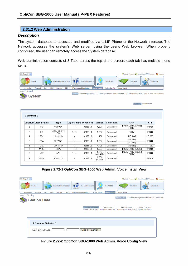
OptiCon SBG-1000 User Manual (IP-PBX Features)
2-47
2.31.2 Web Administration
Description
The system database is accessed and modified via a LIP Phone or the Network interface. The
Network accesses the system‟s Web server, using the user‟s Web browser. When properly
configured, the user can remotely access the System database.
Web administration consists of 3 Tabs across the top of the screen; each tab has multiple menu
items.
Figure 2.72-1 OptiCon SBG-1000 Web Admin. Voice Install View
Figure 2.72-2 OptiCon SBG-1000 Web Admin. Voice Config View

OptiCon SBG-1000 User Manual (IP-PBX Features)
2-48
Figure 2.72-3 OptiCon SBG-1000 Web Admin. Voice Maint View
For more information on database administration and maintenance, refer to the detailed feature
description and operation.
Operation
Operation is detailed in the each feature description and operation.
Conditions
Programming
Related Features
Keyset Administration
Hardware
2.32 TRAFFIC ANALYSIS
Description
The OptiCon SBG-1000 monitors, stores and periodically or upon request outputs various traffic
statistics covering system resources. The output from the system can be used to:
Monitor and evaluate system performance
Observe usage trends and recommend possible corrective actions,
Determine possible trunk problems (i.e. blocking level too high), and/or
Recommend system upgrades.
OptiCon SBG-1000 User Manual (IP-PBX Features)
2-49
Attendants enable Periodic Reporting. Once enabled, the system continues to monitor and output
the requested report until the Periodic Report is disabled. On demand reports selected by the
Attendant. The Traffic Report is sent to the defined TCP port.
System resources covered by Traffic Reports are:
Attendant Traffic Report
Call Summary Report
Hourly Call Report
H/W Unit Usage Summary Report
CO Summary Report
Hourly CO Report
Summary Traffic Reports cover one of five Analysis periods selected at time of print:
Today‟s peak activity hour (within 24 hours)
Yesterday‟s peak activity hour (24 hours prior to Today‟s activity)
Last hour activity
Today‟s total activity
Yesterday‟s total activity.
Operation
Attendant
To print the All Summary Traffic Report periodically:
1. Press the [PGM] button.
2. Dial 0122 (All Summary report code).
3. Select hour for print (00-23).
4. Select minute for print (00-59).
5. Select Analysis Period (1-5).
6. Press the [SAVE] button.
To cancel the periodic All Summary Report:
1. Press the [PGM] button.
2. Dial 0123 (Cancel All Summary report code).
To print a traffic report:
1. Press the [PGM] button.
2. Dial 0121, or 0124-0129 (report code),
0121 All Summary Traffic Reports
0124 Attendant Traffic Report
0125 Call Summary Report
0126 Hourly Call Report
0127 Hardware Usage Summary Report
0128 CO Summary Report
0129 Hourly CO Report
3. Press the [SAVE] button.
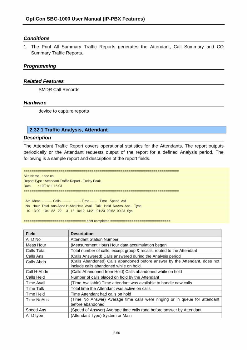
OptiCon SBG-1000 User Manual (IP-PBX Features)
2-50
Conditions
1. The Print All Summary Traffic Reports generates the Attendant, Call Summary and CO
Summary Traffic Reports.
Programming
Related Features
SMDR Call Records
Hardware
device to capture reports
2.32.1 Traffic Analysis, Attendant
Description
The Attendant Traffic Report covers operational statistics for the Attendants. The report outputs
periodically or the Attendant requests output of the report for a defined Analysis period. The
following is a sample report and description of the report fields.
================================================================================
Site Name : abc co
Report Type : Attendant Traffic Report - Today Peak
Date : 19/01/11 15:03
================================================================================
Atd Meas --------- Calls --------- ------ Time ------ Time Speed Atd
No Hour Total Ans Abnd H-Abd Held Avail Talk Held NoAns Ans Type
10 13:00 104 82 22 3 18 10:12 14:21 01:23 00:52 00:23 Sys
================================ print completed ===============================
Field Description
ATD No Attendant Station Number
Meas Hour (Measurement Hour) Hour data accumulation began
Calls Total Total number of calls, except group & recalls, routed to the Attendant
Calls Ans (Calls Answered) Calls answered during the Analysis period
Calls Abdn (Calls Abandoned) Calls abandoned before answer by the Attendant, does not include calls abandoned while on hold.
Call H-Abdn (Calls Abandoned from Hold) Calls abandoned while on hold
Calls Held Number of calls placed on hold by the Attendant
Time Avail (Time Available) Time attendant was available to handle new calls
Time Talk Total time the Attendant was active on calls
Time Held Time Attendant had calls on hold
Time NoAns (Time No Answer) Average time calls were ringing or in queue for attendant
before abandoned
Speed Ans (Speed of Answer) Average time calls rang before answer by Attendant
ATD type (Attendant Type) System or Main

OptiCon SBG-1000 User Manual (IP-PBX Features)
2-51
Operation
Attendant
To print the Attendant Traffic Report:
1. Press the [PGM] button.
2. Dial 0124 (Attendant Traffic report code).
3. Select Analysis Period (1-5).
4. Press the [SAVE] button.
Conditions
1. The Peak Hour is the hour when the system has the highest total call volume.
Programming
Related Features
SMDR (Station Message Detail Recording)
Hardware
Device to capture reports
2.32.2 Traffic Analysis, Call Reports
Description
Call activity statistics are provided in the Hourly Call Reports.
Hourly Call Report
The Hourly Call Report covers hourly completed call activity for the selected Analysis period. The
report indicates the number of completed calls for each hour during the Analysis period as shown:
================================================================================
Site Name :
Report Type : Call Hourly Report
Date : 19/01/11 15:38
================================================================================
Anal Hour # Calls Completed
15:00 0
14:00 0
…..
…..
17:00 211
16:00 543
Total Calls : 754
================================ print completed ===============================

OptiCon SBG-1000 User Manual (IP-PBX Features)
2-52
Operation
Attendant
To print the Hourly Call Report
1. Press the [PGM] button.
2. Dial 0126 (Hourly Call report code).
Conditions
Programming
Related Features
SMDR (Station Message Detail Recording)
Hardware
Device to capture reports
2.32.3 Traffic Analysis, H/W Usage
Description
The Hardware Usage report provides statistics for the system‟s special Hardware resources such
as the VSF as shown in the following sample report.
================================================================================
Site Name : abc co
Report Type : H/W Unit Usage Summary Report - Today Peak
Date : 19/01/11 14:52
================================================================================
Unit Num Anal Total Total
Type Unit Hour Req Denied
VSF 4 00:00 0 0
================================ print completed ===============================
Operation
Attendant
To print the Hardware Usage Summary Report:
1. Press the [PGM] button.
2. Dial 0127 (H/W Usage Summary report code).
3. Select Analysis Period (1-5).
4. Press the [SAVE] button.
Conditions

OptiCon SBG-1000 User Manual (IP-PBX Features)
2-53
Programming
Related Features
SMDR (Station Message Detail Recording)
Hardware
Device to capture reports
2.32.4 Traffic Analysis, CO Reports
Description
The CO Traffic Summary and Hourly reports provide statistics on a summary or hourly basis for
CO Group activity. The following provides a sample report and description of the major fields in the
report.
================================================================================
Site Name : abc co
Report Type : CO Group Summary Report - Today Peak
Date : 19/01/11 19:43
================================================================================
Peak Hour For All CO: 10:00
Grp Num Anal Total Total Inc. Out. Grp % %
No COs Hour Usage Seize Seize Seize Ovfl ACB FAO
1 6 10:00 1 3 0 3 0 0 ---
2 2 00:00 0 0 0 0 0 0 ---
================================ print completed ===============================
Field Description
Grp No. CO Group number
Num COs The number of CO lines in the group
Anal Hour (Analysis hour) hour during the analysis period with peak usage.
Total Usage Total number of call attempts on CO lines in the Group
Total Seize Total number of times CO lines in the group were used for any call
Inc Seize (Incoming Seizures) Total number of incoming calls answered for CO
lines in the group.
Out Seize (Outgoing Seizures) Total number of outgoing calls attempted on CO
lines in the group.
ACB (All COs Busy) Percentage of the time that all CO lines in the group
were simultaneously busy.
FAO (Failed Attempts Outgoing) Percentage of outgoing calls offered to the
CO lines in the group that were denied due to All Trunks Busy
condition.

OptiCon SBG-1000 User Manual (IP-PBX Features)
2-54
Operation
Attendant
To print the CO Traffic Summary Report:
1. Press the [PGM] button.
2. Dial 0128 (CO Traffic Summary report code).
3. Select Analysis Period (1-5).
4. Press the [SAVE] button.
To print the CO Hourly Traffic Report:
1. Press the [PGM] button.
2. Dial 0129 (CO Hourly Traffic report code).
3. Select CO Group (00-05).
Conditions
Programming
Related Features
SMDR (Station Message Detail Recording)
Hardware
Device to capture reports
2.33 VSF INTEGRATED AUTO ATTD/VOICE MAIL
2.33.1 VSF
Description
The Voice Store & Forward (VSF) unit, which is equipped in OptiCon SBG-1000, provides the
system memory to support the integrated Auto Attendant, Voice Mail and system announcement
applications available in the System. The memory is employed to store Auto Attendant
announcements, voice mail, greetings and messages, and various system prompts. The system
prompts (time, date, etc.) are used by the Auto Attendant and Voice Mail applications as well as
other system features. The VSF has a storage capacity of up to 240/480 minutes of announcement
and message storage; approximately 10 minutes of storage is generally used for fixed system
prompts. The capacity of VSF storage depends on the lock key for the VSF Memory Extend.
2.33.2 VSF-Auto Attendant
Description
When a call comes into the system through a CO line, the call may be routed to one of 70 user
recorded VSF Announcements. An announcement is assigned as a Station Group announcement

OptiCon SBG-1000 User Manual (IP-PBX Features)
2-55
or as Auto Attd announcement with an CCR Table that permits Caller Controlled Routing (CCR).
Station Group announcements are played when a call is routed to the group based on definitions in
the Station Group Attributes.
For an Auto Attd Announcement the system will play the announcement and monitor for digits from
the connected external party. A CCR Table defines a dialed digit (0 – 9) to a route. Each single
digit is defined a corresponding route:
Station
Station group
Speed Dial number
Page Zone
Voice Mail
VSF Announcement
In addition, the system will monitor digits for a station number. If the user dials a station number,
the Auto Attd will complete an unsupervised call transfer to the station.
Operation
Attendant
To record an Auto Attd Announcement:
1. Press the [PGM] button.
2. Dial 05 (Message Record code).
3. Dial the appropriate number from 001-072 (Announcement number).
4. The current announcement is played followed by the Press # to record prompt.
5. Dial „#‟.
6. After the record prompt and beep-tone, record message.
7. Press the [SAVE] button to stop recording and save the message.
To delete a recording:
1. Press the [PGM] button.
2. Dial 05 (Message Record code).
3. Dial the appropriate number from 001-072 (Announcement number).
4. The current announcement is played followed by the “Press # to record” prompt.
5. Dial „#‟.
6. Press the [SPEED] button during playback to erase message
System
Operation of the CCR Tables and Auto Attendant are automatic.
Conditions
1. There are no individual time limits on an Auto Attendant announcement.
2. The external caller may receive a ring-back tone before playback of a VSF announcement.
3. The Attendant must “Save” a recording before returning to the on-hook state, otherwise, the
existing recording is used.

OptiCon SBG-1000 User Manual (IP-PBX Features)
2-56
4. To record or delete an Auto Attendant message, all of the VSF channels must be idle.
5. The external caller may dial at any time during an Auto Attendant announcement and must
dial prior to the expiration of the CCR Analysis timer.
6. If the external caller dials an invalid selection or station, the system will play the „Invalid Entry‟
prompt and allow re-entry using the DISA Retry Counter.
7. If the external caller dials more than a single digit, the call is routed based on the System
Numbering Plan.
8. Calls routing by an Auto Attendant (CCR) Announcement are interactive DISA calls and are
subject to conditions of a DISA call.
9. The „*‟ digit is reserved in the CCR Tables to repeat the current or previous Auto Attd
announcement.
10. The „#‟ digit is reserved for callers to access their Voice Mail-box remotely.
11. A CCR Announcement may be programmed to disconnect after playing.
12. The Auto Attd Announcement feature is supported for DISA and DID calls.
13. System announce number 71 is for the MOH.
Programming
VOICE CONFIG Station Group Data
CO Line Data – Call Routing by Line
CO Line Data – Ring Assignment Table
CO Line Data – Call Routing by Auto Attendant
System Data – Call Feature Timer – VSF User Maximum Record Timer
System Data – Call Feature Timer – VSF Valid User Message Timer
Related Features
Station Groups
Remote Message Retrieval
Hardware
VSF
2.33.3 VSF Voice Mail
2.33.3.1 Message Storage
Description
When a station activates Call Forward to the VSF Group, a call is transferred to a VSF mail box or
a transferred call recalls to the VSF, the call is handled by the OptiCon SBG-1000 Mail application.
The caller connects to the called station‟s User Greeting followed by a beep tone.
The remote caller can record a message and hang-up or dial „*‟ for further options. When
disconnect occurs, the VM application stores the message in the called user‟s voice mail-box and
activates the Message Waiting indication at the user‟s station.

OptiCon SBG-1000 User Manual (IP-PBX Features)
2-57
Operation
Remote Caller
To leave a voice message after hearing announcement:
1. Wait for the beep, then leave a message.
2. Hang up to quit recording,
Or,
2. Dial „*‟ for more options.
Conditions
1. Two timers are provided to control voice message length. The Valid User Message Timer
establishes the minimum voice message length; voice messages shorter than this timer are
not stored. The VSF User Maximum Record Timer establishes the maximum voice message
length; when the VSF User Maximum Record Timer expires while recording a voice
message, confirmation tone is heard and the message is saved for the destination station.
2. If all the VSF channels are in use, the Ring Back tone is provided until a VSF channel is
available.
3. All stations including, SLTs can leave and receive voice messages.
4. Individual User Greetings and Voice Mails are protected from AC power loss.
Programming
VOICE CONFIG Station Data – Preset Call Forward – Transfer Mail Box
System Data – Call Feature Timer – Call Forward No Answer Timer
System Data – Call Feature Timer – VSF User Maximum Record Timer
System Data – Call Feature Timer – VSF Valid User Message Timer
Related Features
Call Forward
Station Message Wait/Call Back
VSF Voice Mail
Call Transfer, Voice Mail
Hardware
VSF
2.33.3.2 Message Retrieval
Description
A user can access their Mail Box locally by placing a call to the VSF Voice Mail group, or from an
LIP Phone, by pressing the [MSG] button, or by pressing a {VMAIL-BOX} button while off-hook
receiving Intercom dial tone.
Prompts are then received to guide the user in the Voice Mail Box operation. The user must enter
a Mail Box number, generally the station number, and a corresponding password in response to
the "Request for Password" ("Please enter your password code.") prompts.

OptiCon SBG-1000 User Manual (IP-PBX Features)
2-58
If the user enters a valid and matching Mail box and password, the "Number of Messages" prompt
(“You have xx new messages, You have yy saved messages.”) is received. At this point, the user
also receives the “VM long option prompt” (“To play new messages, press one, to play saved
messages, press two, to set greeting or password, press eight, to disconnect, press pound, Press
0 for the operator, Press nine to hear this message again.”).
When the user responds by dialing 1, the first new message is played. At the end of message
playback, the "New Message option" prompt is played (“To replay message, press one, to listen to
the next message, press two, to delete message, press three, to forward message, press four, to
call the sender, press five, to skip message, press six, to return to main menu, press nine.”). This
process is repeated until the last new message is played and the "No Message" prompt (“No
Messages") is played.
When the user dials 2 in response to the "Number of Messages" prompt, the first-saved message
is played. At the end of the message, the "Saved Message option" prompt is played (“To replay
message, press one, to listen to the next message, press two, to delete message, press three, to
forward message, press four, to call the sender, press five, to return to main menu, press nine.”).
This process is repeated until the last new message is played and the "No Message" prompt (“No
Messages") is played.
In addition to the options indicated in the prompt, a user can record a memo, which is attached to
the current voice mail by dialing the digit 7. The current voice mail and memo can then be
forwarded to other Smart Business gateway users.
When the user dials 9 in response to the "Number of Messages" prompt or during or at the end of
a message the "VM long Options" prompt is played.
Operation
LIP Phone
To assign a {vmail-box} Flex button:
1. [PGM] + {FLEX} + VM group + Mail-box (station) number + [SAVE]
To retrieve Voice Mail locally:
1. Lift the handset or press the [SPEAKER] button.
2. Press [MSG] button; the message contents summary is shown.
1. ICM MWI(001)
2. VSF MSG(002)
3. Dial digit „2‟ to select VSF Messages
4. Dial the Mail Box and corresponding password to receive the “Number of Messages” prompt.
5. Dial desired option code.
6. At completion of session, hang-up to return to idle.
Or,
1. Lift the handset or press the [SPEAKER] button
2. Press {VMAIL-BOX} button.
3. Dial the Mail Box and corresponding password to receive the “Number of Messages” prompt.

OptiCon SBG-1000 User Manual (IP-PBX Features)
2-59
4. Dial desired option code.
5. At completion of session, hang-up to return to idle.
To attach a memo to the current voice message:
1. During or after the New or Old Message option prompt, dial „7‟.
2. At the beep, record the memo.
3. Dial „*‟ to stop recording and store the memo.
4. During or after the New/Old option prompt, dial 4 to forward the message and memo.
SLT
To retrieve Voice Mail locally:
1. Lift the handset.
2. Dial the Voice Mail Group to receive the “Mail Box & Password” prompts sequentially.
3. Dial the Mail Box and corresponding password to receive the “Number of Messages” prompt.
4. Dial desired option code.
5. At completion of session, hang-up to return to idle.
To attach a memo to the current voice message:
1. During or after the New or Old Message option prompt, dial „7‟.
2. At the beep, record the memo.
3. Dial * to stop and store the memo.
4. During or after the New Old option prompt, dial „4‟ to forward the message and memo.
Conditions
1. If no new/old messages are available, pressing „1‟ or „2‟, is an invalid operation and the user
receives the “Invalid Entry” prompt or “No Message” prompt.
2. If the dialed number is not recognized, the "Invalid Entry" prompt is played. After the second
invalid entry, the user is disconnected.
3. The user may dial digits at any time during a voice mail playback, system prompt or silence;
the user must dial a digit in response to a system prompt within the CCR Analysis timer or
the system will disconnect and return error tone.
4. Messages are retrieved in LIFO (Last in First out) order.
Programming
Related Features
Message Retrieval Options
Remote Message Retrieval
Hardware
VSF

OptiCon SBG-1000 User Manual (IP-PBX Features)
2-60
2.33.3.3 Remote Message Retrieval
Description
The system permits remote users access to their mailbox. After accessing the VSF Voice Mail,
operation follows the local procedures.
Operation
Remote Caller
To access Voice Mailbox from a remote location
1. Lift the handset.
2. Dial the telephone number of a DISA assigned CO line assigned for answer by a VSF Auto
Attd.
3. Upon answer, dial „#‟ to receive the “Request for Mail Box number” prompt.
4. Follow local access procedures.
Conditions
1. The conditions associated with Message Retrieval and Message Retrieval Options apply.
2. The conditions associated with DISA apply.
Programming
Related Features
Message Retrieval Options
VSF-Auto Attendant
Message Retrieval
Hardware
VSF
2.33.3.4 Message Retrieval Options
Description
The user may dial the digit 9 to receive the “VM Long Options” prompt while in the Voice Mail Box,
including during or after a voice message or system prompt, except when an option has been
selected that requires user dialing. Some options involving user dialing include the Message
Retrieval Option 1/2 (Play New/Saved Message), 7 (Cancel or Forward message, Remote Access
Only) or 8 (Mail Box settings), refer to Table. The “VM long Options” prompt is:
"To play new messages, press one, to play saved messages, press two, to set station forwarding,
press seven (This option is available only for remote access), to set greeting or password, press
eight, to disconnect, press pound, Press 0 for the operator, Press nine to hear this message
again."
The VSF Voice Mail will respond to incoming digits as shown in the following table.

OptiCon SBG-1000 User Manual (IP-PBX Features)
2-61
Digit Function
1 Play New Msg
2 Play Saved Msg
7 Set Cancel/Fwd, available only for remote access
8 Mail Box Setting, "Mailbox Settings" prompt
9 VM Long options
# Drop, "Goodbye”
0 Attd Call, Call to Attendant.
Operation
LIP Phone
To access a Message Retrieval option
1. At any time after the “Number of Messages” prompt, dial a Message Retrieval Option digit. The
system initiates the selection providing any needed prompts.
SLT
To access a Message Retrieval option
1. At any time after the “Number of Messages” prompt, dial a Message Retrieval Option digit. The
system initiates the selection providing any needed prompts.
Conditions
1. The user must begin dialing within the CCR Analysis timer in response to a system prompt. If
the timer expires, the system will disconnect the call and the user will receive an error tone.
2. If the user remains off-hook after a call placed through the voice mail is complete, the user
will be returned to the previous place in the Voice Mail Box. If the user hangs up, the VSF will
recall at the user Station, and upon answer will play “Request Mail Box Number” prompt.
Programming
Related Features
Message Retrieval
Remote Message Retrieval
Voice Mailbox Settings
Hardware
VSF
2.33.3.5 E-Mail Notification
Description
With the VSF, the system stores the voice message and sends an e-mail to the e-mail address
associated with the station as notification of the new voice message. The voice message can be
attached to the e-mail as a wav file.

OptiCon SBG-1000 User Manual (IP-PBX Features)
2-62
Operation
System
System automatically sends e-mail to notify user of new voice message.
Conditions
1. The voice message is stored in the VSF as well as being attached to the e-mail. The voice
message must be expressly deleted from the VSF even if the e-mail is deleted.
2. The e-mail is sent to the address assigned for the station with the “sender” address defined
for the VSF. Note the latter is required, as many e-mail servers will reject anonymous e-
mails.
3. The e-mail address for the VSF and the station is defined under the Web Admin.
4. The Voice message can be attached to the e-mail notification as a .wav file, if the Attach
Message option is enabled. If disabled, the notification e-mail does not include an attached
wav file.
Programming
VOICE CONFIG Station Data – Station Voice Mail Attributes – VSF MSG
Related Features
VSF-Auto Attendant
Hardware
VSF
2.33.3.6 Voice Mail Back-up Station
Description
With the VSF, an OptiCon soft-phone (Phontage) user receives notification of new messages for
assigned stations. The soft-phone will indicate the total messages for the assigned stations and
the soft-phone. The soft-phone user can download the messages for other stations to the hard
drive of the soft-phone PC and, using the soft-phone application, manage the messages on the
hard drive. If enabled, the soft-phone user may delete voice messages from the VSF memory.
Operation
System
System automatically notifies back-up station of new messages.
Phontage
See Phontage Guide.
Conditions
1. Voice messages are stored in the VSF and must be expressly deleted. Deleting messages
from the soft-phone hard drive does not delete the message from the VSF memory.

OptiCon SBG-1000 User Manual (IP-PBX Features)
2-63
2. It is not possible to backup VSF Messages to Phontage PC when Phontage is connected
remotely in R/NAPT mode.
Programming
VOICE CONFIG Station Data – Station Voice Mail Attributes – VSF Backup
Related Features
VSF-Auto Attendant
Hardware
VSF
2.33.3.7 Voice Mailbox Settings
Description
The user can program the Mail Box settings for their mailbox including a security password and a
greeting. When a user presses "8" while retrieving messages, the "Mailbox Setting" prompt, (“To
edit your greeting, press one, to edit you password, press two. To return to main menu, press
nine”).
Operation
To program Mail Box settings while “in” the Voice Mail Box:
1. Press „8‟, for Mail Box settings; the “Mail Box Setting” prompt is received.
To enter a new password:
1. Dial „2‟ to receive the “Password Entry” prompt (“Please enter your new password and press
pound when finished.").
2. Dial new password.
3. Press „#‟; the “Reenter Password” prompt will be heard ("Please re-enter your password to
confirm and press pound when finished.").
4. Dial new password again.
5. Press „#‟ and the “Password Confirmation” prompt will be heard ("Your password is saved.").
To create a new greeting:
1. Dial „1‟ to hear the “Greeting Option” prompt ("To listen to your current greeting, press five to
record a new greeting, press seven, to return to the main menu, press nine.”).
2. Dial „5‟, to hear your greeting.
OR
3. Dial „7‟ to hear the “Record Greeting” prompt ("At the tone, record your new greeting, press #
when done.").
4. After the beep, record your desired greeting speaking in a normal voice.
5. Press „#‟ and receive the “Greeting Confirmation” prompt ("Your greeting is saved.").

OptiCon SBG-1000 User Manual (IP-PBX Features)
2-64
Conditions
1. If the user is external, the user must begin dialing within the CCR Analysis time, if not the call
is released.
2. If the dialed number is not recognized, the "Invalid Entry" prompt is played.
3. The user must assign a password (Authentication code, up to 12 digits) before access to the
mailbox will be allowed.
NOTE: A greeting does not have to be recorded.
Programming
Related Features
Message Storage
Message Retrieval
Remote Message Retrieval
Message Retrieval Options
Hardware
VSF
2.33.3.8 Call Forward from VM
Description
External users can activate or deactivate Call Forward for their station. Pressing „7‟ while retrieving
messages will return the "Mailbox Set Forward" prompt, (“To forward calls to another extension,
press one. to cancel forwarding, press 2 to return to the main menu, press nine.”).
Operation
To activate Call Forward while in the VM:
1. Press „7‟, for Mail Box set forward, the “Mail Box Set Forward” prompt is received.
To activate Call Forward:
1. Dial „1‟ and receive the “Password Entry” prompt (“Please enter the number to forward to ...").
2. Dial the Station Number as follows:
To forward to another station, dial the station number.
To forward calls Off-net, dial „*‟ and enter Individual Speed number. If the Individual Speed
bin is valid, the confirmation announcement “forwarded to station ('xxx')” or “forwarded to
speed bin number (yyyy)” is played.
To deactivate Call Forward:
1. Dial „2‟ and receive the “Station forwarding is canceled” prompt.
To return to the Main menu:
1. Dial „9‟ and receive the “Mail Box Settings” prompt.
OptiCon SBG-1000 User Manual (IP-PBX Features)
2-65
Conditions
1. If the user is external, the user must begin dialing within and dial subsequent digits within the
VSF Inter-Digit Timer; if not, the call is released.
2. This Mail Box Set Forward is only available for external users.
Programming
Related Features
Message Storage
Message Retrieval
Remote Message Retrieval
Message Retrieval Options
Hardware
VSF
2.33.3.9 Outbound Message Notification
Description
The VSF is able to dial an external number to notify a user of a new voice message. The system
employs the mobile extension number registered for the station receiving the message. When a
caller leaves a message with notification configured, the system places a call to the registered
mobile extension. When the user answers, the extension prompt is played followed by the new
message prompt, (“You have xx new messages.”). The new message prompt indicates the number
of unheard messages.
The user must listen to the new message to confirm the notification. If the user takes no action
within the CCR Inter-digit timer or hangs-up, the call is disconnected and the system will retry the
call after the retry timer expires, until the user listens to the message or the number of attempts
reaches the retry counter. If the user does not answer, the ISDN or VoIP connection times out or
disconnects before answer, or is busy, the system disconnects the notification and will retry the call
after the retry timer. The system will retry the notification until the notification is successful or the
number of call attempts reaches the Retry count.
Operation
Operation of message notification is automatic when configured.
Condition
1. Outbound notification over a PSTN line is not available.
2. Caller Id will be the external caller who left the message or, for messages from another
station, Caller Id will be the station receiving the message.
3. If VSF Notify is changed to „Not Use‟, any existing notification will be terminated after the
initial notification call.
OptiCon SBG-1000 User Manual (IP-PBX Features)
2-66
4. For proper operation, the Station COS and CO Group access for the station must be such as
to allow the notification call.
5. The destination of the notification is the Mobile telephone number assigned in Mobile
Extension table.
6. If all lines in the assigned CO group are busy when the system attempts to place the
notification call, the System will continuously try to seize CO line until a line is successfully
seized.
7. The Retry counter is incremented after the system access the CO line for notification.
8. The Retry count is from 1 to 9; the retry interval is from 1 to 3 minutes.
9. If a new message is logged before answer of the notification call, the message will be
available to the user and a new notification is not invoked. If a new message is received after
answering the notification call, the System will invoke another notification call. The user will
receive the notification after returning to idle.
Programming
VOICE CONFIG Station Data – Mobile Extension
Related Features
Mobile Extension
Message Retrieval
Remote Message Retrieval
Message Retrieval Options
Hardware
VSF
2.33.4 Company Directory
Description
This feature allows a caller reaching Call Routing destination to utilize the DTMF keys to “spell” the
name of a subscriber and be directed to their extension.
If system checks and finds subscriber stations, Company Directory First Name and Last Name has
to be preprogrammed and station‟s Subscriber Name has to be prerecorded in each station. When
station users record his subscriber name, users can record by dialing Company Directory Name
code.
Operation
To record Company Directory Name:
1. Dial the Company Directory Name code.
2. Choose the Recording menu of Subscriber Name, 1.
3. After recording announcement, record subscriber name.
To delete Company Directory Name:
1. Dial the [Company Directory Name] flexible number.
2. Choose the Deleting menu of Subscriber Name, 2.

OptiCon SBG-1000 User Manual (IP-PBX Features)
2-67
To use Company Directory Feature:
When outside caller reaches Company Directory as destination, the system will prompt “Press
one to search by first name”, “Press two to search by last name”, then “Enter the first 3
characters of the person‟s first name” or “Enter the first 3 characters of the person‟s last name”
Once 3 characters have been entered, the system will check the entered characters for a match
to the programmed name in Station Voice Mail Attributes menu (Company Directory First Name
and Last Name). System will search an entry only among those who have recorded the
subscriber name.
If a match is found, the system will play “transferring to [programmed name]” and transfer the call
to the station. Call will be transferred once the prompt is finished.
If more than one match is found, the system will play:
“for [subscriber name], press 1”
“for [subscriber name], press 2”
…
“for [subscriber name], press 9”
When the caller enters the desired digit, the system will route the caller to that station
Condition
1. To be searched in company directory, subscriber name must be recorded. And the first and
last name also should be programmed properly.
2. This feature works only when Station VM Feature Usage is set to “ON”.
Programming
VOICE INSTALL CO Line Registration – SIP ID Configuration
VOICE CONFIG Station Data – Station Voice Mail Attributes – Company Directory
CO Line Data – Call Routing by Called Number
CO Line Data – Call Routing by Auto Attendant
System Data – System Attributes – Station VM Feature Usage
Related Features
Hardware
VSF
2.33.5 Record VM Greeting using Call Routing
Description
This feature provides an option to record a System (001-072) greeting by reaching Call Routing
destination.
Administrator can assign VM Greeting option at Call Routing destination.
Operation
To use Record VM Greeting Feature:

OptiCon SBG-1000 User Manual (IP-PBX Features)
2-68
1. When outside user reaches recording VM greeting as destination, system prompts “enter
password” prompt.
2. User enters system attendant‟s station number and password.
3. “Enter system greeting number” is played.
4. User enters 3 digits system greeting number 001 ~ 072.
5. “To record a new greeting, press pound” is played. And then if there is a recorded greeting,
the greeting is played.
6. User dials „#‟.
7. “Begin recording” is played and confirm tone is heard.
8. User records the greeting and dials „#‟ to finish.
9. System goes to step 5 above. So, “Enter system greeting number” is played.
10. User can hang up.
Condition
1. This feature works only when Station VM Feature Usage is set to “ON”.
Programming
VOICE INSTALL CO Line Registration – SIP ID Configuration
VOICE CONFIG CO Line Data – Call Routing by Called Number
CO Line Data – Call Routing by Auto Attendant
System Data – System Attributes – Station VM Feature Usage
Related Features
Hardware
VSF
2.33.6 Administrator Mailbox
Description
This feature provides a mailbox that has administrative interface via telephone commands to
perform common tasks associated with the VM. In addition, administrator mailboxes may be used
to record a broadcast message which is delivered to all mailboxes.
Operation
Station Voice Mail Attributes menu in Web Admin has “Administrator MailBox” option to mark the
mailbox with administrative options.
If a mailbox is marked as an administrator, the main prompt will offer “to access administrative
options, press six”
After pressing 6, the options that can be performed from the mailbox are:
Administrator Mailbox
To add a mailbox, press 1

OptiCon SBG-1000 User Manual (IP-PBX Features)
2-69
To delete a mailbox, press 2
To reset a mailbox password, press 3
To record a mailbox greeting, press 4
To record a broadcast message, press 5
To record a mailbox name, press 6
Add mailbox [1]
“Please enter the mailbox number”
“Enter COS 1-5”
“Press 1 to confirm or # to cancel and go back to administration main”
When confirmed, the specified station can access to VSF.
Delete mailbox [2]
“Please enter the mailbox number”
“Press 1 to confirm or # to cancel and go back to administration main”
When confirmed, the specified station cannot access to VSF.
Reset mailbox password [3]
“Please enter the mailbox number”
“Press 1 to confirm or # to cancel and go back to administration main”
The password for station is defaulted to be empty. [Authorization Code & COS]
Station password is used for mailbox access in SBG.
Record Mailbox greeting [4]
“Please enter the mailbox number”
“to listen press 1, to record press 2, to delete press 3.”
“Press # to cancel and go back to administration main”
Record a broadcast message [5]
“Please enter the mailbox number” (01-10)
“to listen press 1, to record press 2, to delete press 3, to send press 4.”
“Press # to cancel and go back to administration main”
Record Mailbox Name [6]
“Please enter the mailbox number”
“to listen press 1, to record press 2, to delete press 3.”
“Press # to cancel and go back to administration main”
Condition
1. There are no limits on the number of mailboxes that can be marked as administrators.
2. The broadcast message is the shared message. System provides broadcast message first
regardless message retrieve option.
3. A station can delete broadcast message without confirmation.
4. Only administrator can delete a recorded broadcast message.
5. This feature works only when Station VM Feature Usage is set to “ON”.
Programming
VOICE CONFIG Station Data – Station Voice Mail Attributes – Administrator MailBox
System Data – System Attributes – Station VM Feature Usage

OptiCon SBG-1000 User Manual (IP-PBX Features)
2-70
Related Features
Hardware
VSF
2.33.7 Announce Only Mailbox
Description
This feature provides a method to mark a mailbox as an announce type. This type of mailbox plays
a greeting only and then returns the caller to the previous menu or hangs up.
Operation
An administration option shall enable/disable the announcement only flag.
An administration option shall allow the selection of previous menu or hang up after the mailbox
greeting. Previous menu is for Call Routing by Auto Attendant feature.
Condition
1. There are no limits on the number of mailboxes that can be marked as announcement only.
Programming
VOICE CONFIG Station Data – Station Voice Mail Attributes – Announce only MailBox
Station Data – Station Voice Mail Attributes – Announce only Option
Related Features
Hardware
VSF
2.33.8 Message Cascade
Description
Message cascading is a feature that copies messages left for the originating mailbox to another
mailbox. Once the message is copied into the other mailbox, notification events can take place
based on that mailbox settings.
Operation
A mailbox has a cascade field in administration. That field is another mailbox number.
A mailbox has a cascade field type in administration. One of the following types may be selected:
Disable - Disable this function.
Copy-Immediately – Copy (Cascading) begins immediately, allowing storage of
duplicate messages in several mailboxes.
OptiCon SBG-1000 User Manual (IP-PBX Features)
2-71
Copy-Urgent Only – Copy (Cascades) only those messages marked urgent.
Move-Immediately – Move (Cascading) begins immediately, allowing storage of
duplicate messages in several mailboxes.
Move-Urgent Only – Move (Cascades) only those messages marked urgent.
Conditions
1. A mailbox can only have 1 cascade mailbox destination.
2. Mailbox messages are retained in each mailbox.
Programming
VOICE CONFIG Station Data – Station Voice Mail Attributes – Cascade MailBox
Station Data – Station Voice Mail Attributes – Cascade Type
Related Features
Hardware
VSF
2.33.9 Class of Service Settings
Description
The system shall provide administrative options to create COS. These COS can then be assigned
to stations/mailboxes on an individual basis.
Operation
The system shall provide 5 COS settings, 1-5.
Each COS has the following items that can be programmed:
1. Greeting length: 0-99 seconds (60 seconds default)
2. Message length: 0- 600 seconds (0 default)
3. Number of messages: 0-250 (0 default) (0- Number of message is the same as system
capacity)
4. Retention time: 0-99 days (0 days default)
5. E-mail notification: Disable/Notification only/ Notification and Delete (default: Notification and
Delete)
6. Future delivery messages: On/Off (Off default)
7. Confirm message receipt: On/Off (Off default)
8. Private message mark: On/Off (Off default)
Conditions
1. The default class of service for all mailboxes is 1. COS 1 contains all default settings.
2. Future delivery message feature is not supported.
3. This feature works only when Station VM Feature Usage is set to “ON”.

OptiCon SBG-1000 User Manual (IP-PBX Features)
2-72
Programming
VOICE CONFIG Station Data – Station Voice Mail Attributes – VM COS
System Data – System Attributes – Station VM Feature Usage
Related Features
Hardware
VSF
2.33.10 Send Message
Description
A user can record the message and send it to other mail box with several options or distribution
list. The VM long option prompt is modified to add “To send a message press 4”.
Operation
To send a message:
1. Record Voice Message
a. User press „4‟ in the main menu and record a message.
b. The prompt will state “At the tone, please leave a message and to stop recording press
pound key”.
2. Decision of Destination
a. The prompt will state “Enter the mail box number or distribution list number followed by
pound. To spell the name, press *”
b. To Mail Box
i. Enter the mail box number
ii. Refer to Step 3.
c. To Distribution List
i. Enter distribution list number and # key.
ii. The prompt will state “Your message has been sent”.
d. To Spell Name
i. Press „*‟.
ii. The prompt will state “Press one to search by first name, Press two to search by
last name”, then “Enter the first 3 characters of the person‟s first name” or “Enter
the first 3 characters of the person‟s last name”
iii. Once 3 characters have been entered, the system will check the entered
characters for a match to the programmed name in Station Voice Mail Attributes
menu (Company Directory First Name and Last Name). System will search an
entry only among those who have recorded the subscriber name.
iv. If a match is found, the system will play:
“for [subscriber name], press 1”
“for [subscriber name], press 2”
…
OptiCon SBG-1000 User Manual (IP-PBX Features)
2-73
“for [subscriber name], press 9”
v. When the caller enters the desired digit, the system will select the destination
station.
vi. Refer to Step 3.
3. Delivery Selection
a. After Step 2-b or 2-d, the prompt will state “For regular delivery, press one. To mark
urgent, press two. To mark private, press 3. To mark urgent and private, press 4. To
request delivery receipt of the message for future, press 5”.
b. Press 1~5, the prompt will state “Your message has been sent”
c. If press 1~4, then refer to “Mark a message private”. Or if press 5, then refer to “Mark a
message for delivery confirmation”
Conditions
1. This option is only played to the mailbox owner if the mailbox COS allows it.
2. This feature works only when Station VM Feature Usage is set to “ON”.
Programming
VOICE CONFIG Station Data – Station Voice Mail Attributes – VM COS
System Data – System Attributes – Station VM Feature Usage
Related Features
Hardware
VSF
2.33.11 Distribution Lists
Description
This allows a mailbox owner to setup a group of mailboxes and send a message using one number
instead of having to enter each mailbox individually.
A maximum of 5 distribution lists can be set up per mailbox.
The VM long option prompt is modified to add “for personal options press 5”.
Operation
To edit a distribution list:
1. Press „5‟ from the main menu, then the prompt will state “to edit a list press 1”.
2. Press „1‟, then the prompt will state “Enter list number 1~5”.
3. Press 1~5, then the prompt will state “to edit a list, press 1, to delete a list, press 2”.
4. Press „1‟, then the prompt will state “to add a mailbox, press 1, to delete a mailbox, press 2,
to listen to mailboxes in list, press 3”.
a. Add mailbox to list
i. Press „1‟, then the prompt will state “Please enter the mailbox number”.

OptiCon SBG-1000 User Manual (IP-PBX Features)
2-74
ii. Enter the station number, then the prompt will state “mailbox XXX added”.
b. Delete mailbox from list
i. Press „2‟, then the prompt will state “Please enter the mailbox number”.
ii. Enter the station number, then the prompt will state “mailbox XXX deleted”
c. Listen to mailboxes in list
i. Press „3‟, then the prompt will state “mailbox XXX” and repeat for all members.
Conditions
1. The maximum number of mailboxes in a distribution list is 25.
2. This feature works only when Station VM Feature Usage is set to “ON”.
Programming
VOICE CONFIG System Data – System Attributes – Station VM Feature Usage
Related Features
Hardware
VSF
2.33.12 Mark a message private
Description
This allows a mailbox owner to mark a message as private, replying to, or creating a message to
another user. These messages cannot be forwarded.
Operation
To mark a message private:
1. After replying to a message, recording a message, the following options will be played:
For regular delivery, press 1.
To mark urgent, press 2.
To mark private, press 3.
To mark urgent and private, press 4
To request delivery receipt of the message for future, press 5
2. Press „3‟ or „4‟.
Conditions
1. Private message cannot be forwarded.
2. This option is only played to the mailbox owner if the mailbox COS allows it.
3. This feature works only when Station VM Feature Usage is set to “ON”.
Programming
VOICE CONFIG Station Data – Station Voice Mail Attributes – VM COS

OptiCon SBG-1000 User Manual (IP-PBX Features)
2-75
System Data – System Attributes – Station VM Feature Usage
Related Features
Hardware
VSF
2.33.13 Mark a message for delivery confirmation
Description
This allows a mailbox owner to mark a message for confirmation of delivery. When the user has
listened to the sent message, a message is dropped in the sender mailbox confirming listen
receipt.
Operation
To mark a message private:
1. After replying to a message, recording a message, the following options will be played:
For regular delivery, press 1.
To mark urgent, press 2.
To mark private, press 3.
To mark urgent and private, press 4
To request delivery receipt of the message for future, press 5
2. Press „5‟
Once the user has listened to a message that has been marked for receipt, the user that marked
the message will get a new message in their mailbox.
When they access this message a prompt will state: “message for XXXX (mailbox #) was listened
to on HH:MM MM/DD”
This message is then treated a normal VM and all options apply.
Conditions
1. This option is only played to the mailbox owner if the mailbox COS allows it.
2. This feature works only when Station VM Feature Usage is set to “ON”.
Programming
VOICE CONFIG Station Data – Station Voice Mail Attributes – VM COS
System Data – System Attributes – Station VM Feature Usage
Related Features
Hardware
VSF

OptiCon SBG-1000 User Manual (IP-PBX Features)
2-76
2.34 WAKE-UP ALARM
Description
This feature allows a user or Attendant to set a wake-up time or desired time to be alerted. When
the time is reached, the system will signal with an audible and visual signal.
Operation
Attendant
To register Wake-Up:
1. Press the [PGM] button.
2. Dial 023 (Attendant Station Program code).
3. Dial the desired station range, for a single station, enter an „*‟ in place of the second station
number.
4. Dial 2-digit hour and 2-digit minute for alerting.
5. For a daily (repeating alarm), dial „#‟.
6. Press [SAVE] button.
To erase Wake-Up:
1. Press the [PGM] button.
2. Dial 024 (Attendant Station Program code).
3. Dial the desired station range, for a single station, enter an „*‟ in place of the second station
number.
4. Press [SAVE] button.
LIP Phone:
To register Wake-Up:
1. Press the [PGM] button.
2. Dial 21 (Set Wake-up code).
3. Dial 2-digit hour and 2-digit minute for alerting (hh:mm).
4. For a daily (repeating alarm), press „#‟.
5. Press [SAVE] button.
To stop the alarm notification:
1. Lift the handset or press [SPEAKER].
To erase Wake-Up:
1. Press the [PGM] button.
2. Dial 22 (Erase Wake-up code).
3. Press [SAVE] button.
SLT
To stop the alarm notification:
1. Lift the handset.

OptiCon SBG-1000 User Manual (IP-PBX Features)
2-77
Conditions
1. When receiving a wake up signal, lifting the handset will be heard Wake-up alarm prompt.
2. The Wake-up alarm Ring signal is 30 seconds, On/90 seconds, Off (3 times). If no action is
taken by the user, the ring signal is given to the Attendant with a display designating the
station number that did not respond.
3. Time (hh:mm) must be entered in the Military 24-hour format.
4. The daily alarm will reset and repeat each day until erased (cancelled)‟ the One-time alarm
will reset and cancel automatically.
Programming
Related Features
Hardware
2.35 DIRECT STATION SELECT/BUSY LAMP FIELD (DSS/BLF)
Description
When a Flex button on an LIP Phone is assigned as a {DSS} button it also serves as a Busy Lamp
Field; the LED indicates the status of the associated station or system facility.
Operation
LIP Phone
Operation of this feature is automatic for assigned Flex buttons.
Conditions
1. A station receiving ICM ringing that is busy will show the DSS button LED on all other
stations flashing at 30 ipm.
2. A station receiving ICM ringing will receive visual indication with a flashing LED of the Flex
button associated with the calling station.
3. When a station receives a Camp-On, the LED of the DSS button associated with the calling
station will flash.
4. The station is considered busy when:
in use,
receiving ICM Ring at an LIP Phone,
receiving any ring at an SLT.
Programming

OptiCon SBG-1000 User Manual (IP-PBX Features)
2-78
Related Features
Intercom Call (ICM Call)
Station User Programming & Codes
Hardware
2.36 INTERCOM CALL (ICM CALL)
Description
A non-blocking ICM is available to all stations in the system. Users may place an intercom call to
other stations in the system by dialing applicable digits as defined in the system Numbering Plan.
Operation
LIP Phone
To place an intercom call:
1. Lift the handset or press the [SPEAKER] button to receive ICM dial tone.
2. Dial station number or press the {DSS/BLF} button.
3. For ring-back tone, await answer or
For Intercom splash-tone, speak and await answer.
SLT
To place an intercom call:
1. Lift the handset to receive ICM dial tone.
2. Dial station number.
3. For ring-back tone, await answer or,
For Intercom splash-tone, speak and await answer.
Conditions
1. Intercom Dial tone will time-out if action is not taken within Dial-Tone Time or, if the time
between digits exceeds the Inter-digit Timer; error tone is received on dial tone time-out.
2. ICM Dial tone is halted after dialing the first digit.
3. If the called station is busy, Intercom Busy tone is provided for the Busy Tone time (7 sec.)
then, Error tone is sent by the system; the caller may disconnect or activate a feature such as
Message Wait/Callback.
4. For LIP Phone users, consecutive Intercom calls can be placed without the need to regain
ICM dial tone (no need to hang-up) between calls; the user simply presses another {DSS/BLF}
button.
5. An Intercom call to a station in the HF answerback or Voice Announce mode (H or P
Intercom Signaling Mode) is not considered answered unless the called user lifts the handset
or presses the [SPEAKER] button (goes off-hook).

OptiCon SBG-1000 User Manual (IP-PBX Features)
2-79
Programming
VOICE CONFIG System Data – Call Feature Timer - ICM Dial Tone Timer
System Data – Call Feature Timer – Inter Digit Timer
Related Features
Intercom Answer Mode
Speakerphone
Hardware
2.37 INTERCOM CALL HOLD
Description
While on an active ICM Call, LIP Phone users can place the ICM Call on hold; the held station will
receive the assigned Music-on-Hold. The call is placed on Exclusive Hold and recalls at the
holding station when the Exclusive Hold Recall timer expires.
Operation
LIP Phone
To assign a {ICM} Flex button:
1. [PGM] + {FLEX} + [PGM] + „53‟ + [SAVE]
To place an active ICM call on hold:
1. Press the [HOLD] button; the ICM dial tone is received and the {ICM} button LED will flash at the
exclusive hold rate and the ICM dial tone is received.
To retrieve the held ICM call:
1. Press the {ICM} button or the {DSS/BLF} button associated with the held station; the {ICM} button
LED will be On and the ICM call connected.
Conditions
1. Only one ICM call may be placed on hold at a time.
Programming
Related Features
MOH (Music-On-Hold)
Intercom Call (ICM Call)
Hold Recall
Hardware
LIP Phone
OptiCon SBG-1000 User Manual (IP-PBX Features)
2-80
2.38 INTERCOM CALLER CONTROLLED ICM SIGNALING
Description
A user can change the signaling mode of an Intercom call from Tone ring to Voice announce, or
Voice announce to Tone ring.
Operation
LIP Phone
To change the ICM Signaling mode:
1. Place intercom call.
2. Dial „#‟, ICM Signaling mode will change from Voice announce to Tone ring or Tone ring to
Voice announce.
SLT
To change the ICM Signaling mode:
1. Place intercom call as normal.
2. Dial „#‟, ICM Signaling mode will change from Voice announce to Tone ring, or Tone ring to
Voice announce.
Conditions
1. If the signaling mode is changed, the call is not subject to Call Forward, No Answer.
2. The signaling mode for a specific Intercom call can only be changed once and can not be
changed back to the original signaling mode.
3. Changing the signaling mode does not affect privacy at the called station.
Programming
Related Features
Intercom Answer Mode
Hardware
2.39 INTERCOM LOCK-OUT
Description
If the user takes no action after going off-hook for the Dial Tone timer or fails to dial an additional
digit within the Inter-digit timer, the station will receive an error tone for 30 seconds and be placed
out-of-service (locked-out). The LED of associated {DSS/BLF} buttons will flutter (flash) rapidly to
indicate the out-of-service status.
For LIP Phone users, if the [SPEAKER] is used, the station will receive an error tone for 30 sec. and
then automatically return to idle.

OptiCon SBG-1000 User Manual (IP-PBX Features)
2-81
Operation
System
Operation of Intercom Lock-out is automatic based on the Dial Tone & Inter-digit timers.
Conditions
1. Error tone is presented for 30 sec. followed by 30 sec. of Howler tone followed by lock-out
and silence.
Programming
VOICE CONFIG System Data – Call Feature Timer - ICM Dial Tone Timer
System Data – Call Feature Timer – Inter Digit Timer
Related Features
Intercom Call (ICM Call)
Hardware
2.40 INTERCOM STEP CALL
Description
When the busy tone is received on a dialed Intercom call, the user may place a call to another
station by dialing the last digit of the station number. The system replaces the last digit of the
previously dialed busy station with the dialed digit and places an Intercom call to the new station
number.
Operation
LIP Phone
To activate step call, while receiving busy on a dialed Intercom call:P
1. Dial a digit other than the last digit of the busy station‟s intercom number.
Conditions
1. If the user dials the last digit of the busy station, Camp-On will be activated.
2. After receiving busy tone, if the user takes no action for the Busy Tone timer, the system will
start the Intercom Lock-out procedure.
3. For Step Call to work, the ICM Station called must have the same digits except for the last
digit.
Programming

OptiCon SBG-1000 User Manual (IP-PBX Features)
2-82
Related Features
Intercom Lock-Out
Intercom Call (ICM Call)
Hardware
2.41 MESSAGE WAIT/CALL BACK
2.41.1 Station Message Wait/Call Back
Description
A station can activate a Message Wait indication requesting a Call Back when the called station
does not answer or is in DND. A station may receive a Message Wait from any number of other
stations in the system. The station receiving the Message Wait can return the calls to the station
using the [MSG/CALLBK] button.
When a busy station is called, the calling user may request to be placed in a queue to receive a
Call Back. When the called station returns to idle, the system signals the initiating station with
Callback ring. When the user answers, the now idle station is called.
Operation
LIP Phone
To leave a Message Wait, while receiving ring back tone or no response on a call announce (H or
P mode):
1. Press the [MSG/CALLBK] button; confirmation tone received.
2. Hang up, Message Wait is activated.
To leave a Message Wait, while receiving DND tone:
1. Press the [MSG/CALLBK] button; confirmation tone received.
2. Hang-up, Message Wait is activated.
To leave a Call Back (queue for a station), while receiving busy notification:
1. Press the [MSG/CALLBK] button; the user receives confirmation tone.
2. Hang up, to return to idle.
To respond to a Call back recall received when the busy station becomes available:
1. Lift the handset, or press the [SPEAKER] button.
2. Previously busy station is called.
To retrieve Station Messages Waiting:
1. Press [MSG/CALLBK] button; either the message contents summary will be shown as below.

OptiCon SBG-1000 User Manual (IP-PBX Features)
2-83
1. ICM MWI(001)
2. VSF MSG(002)
2. Dial „1‟ to select ICM MWI (Station Message Wait)
„1‟ – ICM MWI, Station Message Wait,
„2‟ – VSF MSG, VSF Message Wait
To return a call from the current Station Message:
1. Press the [SAVE] button.
To delete the first Message Wait from the list:
1. Press „*‟ button
2. Press „1‟ button to confirm the deletion, the list is updated removing the first station number in
the list.
To delete all Message Waits:
1. Press „*‟ button.
2. Press „3‟ button.
SLT
To leave a Message Wait, while receiving ring back tone or no response on a call announce (H or
P mode):
1. Momentarily press the hook switch.
2. Dial 56 (Message Wait/Call Back code).
3. Hang up, Message Wait is activated.
To leave a Message Wait, while receiving DND tone:
1. Momentarily press the hook switch.
2. Dial 56 (Message Wait/Call Back code).
3. Hang up, Message Wait activated.
To retrieve a Station Message Wait:
1. Dial 57 (Message Wait/Call Back Answer code).
To leave a Call Back (queue for a station), while receiving busy:
1. Momentarily press the hook switch.
2. Dial 56 (Message Wait/Call Back code).
3. Hang up, return to idle.
To respond to a Call back recall, received when the busy station becomes available:
1. Lift the handset.
2. Previously busy station is called.
Conditions
1. A Message Wait/Call Back return call will always ring at the receiving station overriding the
Intercom signaling mode selected.
2. A station can leave only one callback request at a time.

OptiCon SBG-1000 User Manual (IP-PBX Features)
2-84
3. If a station is attempting to leave a message and the system Message Wait queue is full, the
station will receive ICM busy tone.
4. A Message Wait reminder tone can be enabled to remind the user of messages waiting.
5. A station in Call Forward can leave a message wait.
6. A Message Wait indication is left at the originally-called station even if the call is forwarded.
7. An LIP Phone with LCD may call back to the station(s) that left messages in any desired
order, or the normal (“oldest first”) order.
8. Placing an Intercom call to a station will cancel any existing Message Wait from that station.
Programming
VOICE CONFIG System Data – Call Feature Timer – MSG Wait Reminder Tone Timer
Related Features
Message Wait Reminder Tone
Hardware
2.41.2 Message Wait Reminder Tone
Description
LIP Phones can be sent a tone as a periodic reminder to the user of message waits in queue. This
tone is sent to the station only while idle and is heard over the speaker.
Operation
System
Reminder tone is sent to stations automatically when assigned.
Conditions
1. Interval set between tones can be 00 to 60 minutes; the 00 setting disables the reminder
tone.
2. The reminder tone will continue until all messages have been retrieved.
3. A station that is busy or in DND will not receive the Message Wait Reminder tone until it
returns to idle.
Programming
VOICE CONFIG System Data – Call Feature Timer – MSG Wait Reminder Tone Timer
Related Features
Message Wait/Call Back
Hardware

OptiCon SBG-1000 User Manual (IP-PBX Features)
2-85
LIP Phone
2.42 PAGING
2.42.1 Paging & All Call Paging
Description
A station can connect and transmit voice announcements to any or all of the system Paging zones.
Stations are grouped into “zones” to receive pages to the zone. Stations not assigned to any zone
will not receive a page including All Call pages.
A page warning tone will be provided to the Paging Zone(s) prior to the audio connection. The user
is allowed to continue the page for the specified Page Time-out timer after which the user is
disconnected and the Paging Zone(s) is returned to idle.
The default Paging Zone dial access codes are as follows:
Paging Zones 501~510
All Call Page 500
Flexible buttons of an LIP Phone may be assigned to access a Paging Zone as a {PAGING ZONE}
button.
Operation
LIP Phone
To assign a Flex button as a {paging zone} button:
1. Lift the handset, and press [PGM] + {FLEX} + Paging Zone number + [SAVE]
To make a page:
1. Lift the handset.
2. Dial the desired paging code or press a {PAGING ZONE} button.
4. After the Page Warning Tone, make announcement.
5. Replace the handset to return to idle.
To queue for a page when busy is received:
1. Press the [MSG/CALLBK] button.
2. Replace the handset to return to idle.
SLT
To make a page:
1. Lift the handset.
2. Dial the desired paging code.
3. After the Page Warning Tone, make announcement.
4. Replace the handset, to return to idle.
To queue for a page when busy is received:
1. Dial 56 (Call Back code).
2. Replace the handset returning to idle.

OptiCon SBG-1000 User Manual (IP-PBX Features)
2-86
Conditions
1. Stations dialing a Page Code will be queued when any of the other Paging zones are busy.
2. If an LIP Phone user attempts to page using the speakerphone, pre-selection will be
activated and display will show "LIFT THE HANDSET TO PAGE".
3. Stations receiving a page are considered idle for other incoming calls and ring will override
Page announcements over an LIP Phone speaker.
4. Stations in DND or busy will not receive Page announcements.
5. A station accessing a Paging Zone is considered busy.
6. Stations which are not included in a Paging Zone will not receive any page, including All Call.
7. A station is permitted only one Paging Zone queue request at a time; if a station attempts
another Paging Zone queue, only the last-received queue request is honored.
8. When a busy Paging Zone becomes idle, the system will select the oldest paging queue, and
signal the appropriate station; the signaled station will have an audible ring (distinctive ring)
indicating the queue callback.
9. The All Call Paging, while signaling the queued station, is considered busy; additionally, All
Call Paging is considered busy when any paging zone is active.
10. The queue recall is always in tone ring mode regardless of the station‟s ICM signaling mode.
11. If the waiting station is idle, the Call Back ring signals the station for 15 sec., after which the
queue is canceled and the next station in the queue is signaled.
12. If the waiting station is busy, and the Paging zone becomes available, the next idle station in
the Paging Queue list is signaled and the busy waiting station is placed at the bottom of the
Paging Queue list. If there is no idle next station in the Paging Queue, the Paging Queue is
canceled.
13. When the waiting station goes to idle, and both a “Paging Queue” and “CO Call back Queue”
exist, the Paging Queue is given priority.
Programming
VOICE CONFIG Station Data – Paging Access
System Data – Call Feature Timer – Paging Timeout Timer
Related Features
Meet Me Page Answer
Hardware
2.42.2 Meet Me Page Answer
Description
Any station may respond to a “Meet Me” Page request over a Paging Zone; the user can answer
the page from any station and be connected to the paging party.
Flexible buttons of an LIP Phone may be assigned as a {MEET ME} button.

OptiCon SBG-1000 User Manual (IP-PBX Features)
2-87
Operation
LIP Phone
To assign a Flex button as a {meet me} button:
1. Lift the handset, press [PGM] + {FLEX} + „511‟ + [SAVE].
To answer a page with Meet Me Page:
1. Lift the handset, or press the [SPEAKER] button.
2. Dial 511 (Meet Me Page code) or press the {MEET-ME} button.
Or
3. Press the [HOLD] button.
SLT
To answer a page with Meet Me Page:
1. Lift the handset to receive intercom dial tone.
2. Dial 511 (Meet Me Page code).
Conditions
1. A Meet Me Page must be answered within the Page Time-out timer.
2. A station may answer a Meet Me Page from any station regardless of pickup/paging group
assignments and page access permission.
3. The paging party must remain off-hook until the paged party answers the Meet Me request;
the initiator may press the Mute button to eliminate transmitting over the page circuit while
waiting for the party to answer.
Programming
VOICE CONFIG System Data – Call Feature Timer – Paging Timeout Timer
Related Features
Paging & All Call Pag
Hardware
2.43 CO RING ASSIGNMENT
Description
Each station in the system can be programmed to provide an audible signal when the system
detects an incoming call on specified CO lines. Separate ring assignments are made for Day, Night
and Timed Ring operation mode. In addition, the audible signal at the station can be delayed by 1
to 9 ring cycles allowing other stations to answer the call first.

OptiCon SBG-1000 User Manual (IP-PBX Features)
2-88
Operation
System
Operation of this feature is automatic.
Conditions
1. Separate assignments are made for stations to ring in the Day, Night, and/or Timed Ring
mode.
2. A busy station receives the Muted ring or Call Waiting tones (as appropriate) for the station‟s
off-hook ring assignment.
3. The system Ring mode can be selected manually or automatically. In Automatic mode,
Day/Night selection is determined based on the Automatic Ring Mode Selection table; the
Attendant has manual control over the Ring mode selection.
4. The Attendant‟s LCD displays Night and Timed Ring Mode and the [DND] button LED will
flash.
5. If a CO line is not assigned to ring at any station, incoming calls on the CO line will ring the
first available Attendant.
Programming
VOICE CONFIG CO Line Data – Call Routing by Line
CO Line Data – Ring Assignment Table
System Data – Day/Night/Timed Schedule
Related Features
Day/Night/Timed Ring Mode
Off-Hook Signaling
Hardware
2.44 CO LINE RELEASE GUARD TIME
Description
To assure that the PSTN switching equipment has sufficient time to restore the idle status, the
system will hold CO lines in a busy state to users after release of a CO line by a station. The time
between station disconnect and when the system changes the CO line status from busy to idle is
the CO Line Release Guard time.
Operation
System
Operation of this feature is automatic.
Conditions

OptiCon SBG-1000 User Manual (IP-PBX Features)
2-89
Programming
VOICE CONFIG System Data – Call Feature Timer – CO Release Guard Timer
Related Features
Hardware
2.45 IP TRUNKING
2.45.1 SIP Service
Description
When assigned to support Session Initiation Protocol (SIP), VoIP channels provide protocol
conversion between SIP and the OptiCon protocol. This permits the VoIP channel to connect to
external SIP networks for call services. In addition, to the IETF RFC-3261 SIP draft standard,
OptiCon SBG-1000 VoIP channels support other SIP-related RFCs including:
RFC-2617 HTTP Authentication, Basic & Digest
RFC-3515 Refer Method
RFC-3264 Offer/Answer Model
RFC-3265 SIP Basic Call Flow Examples
RFC-3891 SIP “Replaces” Header
Using the SIP database assignments, the system will register and authenticate with the SIP proxy
server permitting the system to interoperate employing SIP to establish, manage and terminate
real-time voice sessions with external parties.
Operation
System
Operation of SIP Service is automatic.
Conditions
Programming
VOICE INSTALL CO Line Registration – Server Information
CO Line Registration – SIP ID Configuration
Related Features
Hardware

OptiCon SBG-1000 User Manual (IP-PBX Features)
2-90
2.46 CALLING/CALLED PARTY IDENTIFICATION
Description
The OptiCon SBG-1000 system receives calling party identification in SIP INVITE message or the
ISDN call Set-up message, Calling Line Identification Presentation (CLIP). The answering party
identification, which may be different from the called party, is received in SIP 200 OK message or
the ISDN connect message, Connected Line Identification Presentation (COLP). When provided,
the LCD of LIP Phones displays the identification, which is included in call records.
LIP Phone Display is shown:
LINE RINGING
CLI 03438502821
The system will also compare the identification to programmed Speed Dial bins; when a match
exists, the Name of the Speed Dial bin displays in place of the number, CO Name display.
The system will send calling and answering party identification in the appropriate messages to SIP
or the ISDN based on the database. Identification messages may be restricted, not reported, to the
far-end user. Calling Line Identification Restriction and Connected Line Identification Restriction
may be enabled in the system database or by {CLIR} and {COLR} Flex buttons.
Operation
System
Operation of this feature is automatic.
LIP Phone
To program {CLIR} button:
[PGM] + {FLEX} + [PGM] + „43‟ + [SAVE]
To program {COLR} button:
[PGM] + {FLEX} + [PGM] + „44‟ + [SAVE]
To activate CLIR or COLR, before placing or answering a SIP call or an ISDN call
1. Press the {CLIR} or {COLR} Flex button.
Conditions
1. This feature may not be available in the specific SIP/ISDN service area or may be a
subscription service.
Programming
Related Features
Hardware

OptiCon SBG-1000 User Manual (IP-PBX Features)
2-91
2.47 ANSWERING MACHINE EMULATION
Description
When a call is sent to a voice mail-box, the associated station can be assigned to notify the user
and allow the user to screen the call. Two methods of notification and call screening are:
Ring mode – the user is notified by the Answering Machine Emulation (AME) Flex
button (if programmed), which will flash; the user may press the Flex button to
screen the caller as the voice message is stored.
Speaker mode - when the call is sent to the Voice Mail-box, the caller‟s voice is
automatically broadcast over the speaker of the user‟s LIP Phone.
The user may terminate screening, and either leave the caller in voice mail to record a message,
talk with the caller and record the conversation in the mail-box, or answer the call and disconnect
the Voice Mail.
The user‟s LIP Phone must be assigned with an AME Flex button for proper operation.
Operation
LIP Phone
To assign an {AME} button:
Ring Mode
1. Lift the handset, and press [PGM] + {FLEX} + „64‟ + „0‟ + [SAVE]
Speaker Mode
1. Lift the handset, and press [PGM] + {FLEX} + „64‟ + „1‟ + [SAVE]
To screen a call in the Ring mode:
1. Press the flashing {AME} button, the caller‟s voice is broadcast over the station speaker and
simultaneously stored in the Voice Mail-box.
To stop the voice broadcast/screening and leave the caller in Voice Mail:
1. Press the illuminated [SPEAKER] button.
To talk with the caller and record the conversation in Voice Mail:
1. Press the illuminated [MUTE] button.
To answer the call and cancel the voice message:
1. Press the illuminated {AME} button, the caller is connected and Voice Mail is disconnected.
Conditions
1. AME is supported only on an LIP Phone (an {AME} Flex button must be assigned on the
phone).

OptiCon SBG-1000 User Manual (IP-PBX Features)
2-92
2. If the user answers the call using the {AME} button, the caller is connected in the normal
manner, the Voice Mail is disconnected, and any message recorded by the caller is not
stored (when VSF is in use).
Programming
Related Features
VSF Integrated Auto Attd/Voice Mail
Hardware
LIP Phone
2.48 AUTO CALLED NUMBER REDIAL (ACNR)
Description
This feature allows a station user to request and have the system retry a busy or no answer
external call until the call is connected or the feature is cancelled.
Operation
LIP Phone
To assign a Flex button as an {redial} button:
1. Press [PGM] + {FLEX} + [PGM] + „54‟ + [SAVE]
To activate ACNR while receiving busy, no answer:
1. Press the {REDIAL} button or [ACNR] soft button.
2. Hang-up handset, or press [SPEAKER].
To cancel ACNR while idle:
1. Press flashing {REDIAL} button or [STOP] soft button.
To cancel ACNR during an ACNR attempt:
1. Lift the handset or press the [MUTE] or flashing {REDIAL} button.
System
1. The system initiates the ACNR process, starting the ACNR Pause Timer.
2. At expiration of the timer, the system attempts the previous call.
3. When the called party answers, the calling user may answer by lifting the handset or using
speakerphone to communicate with called party.

OptiCon SBG-1000 User Manual (IP-PBX Features)
2-93
Conditions
1. Four timers and a retry counter can be programmed.
ACNR Pause Timer – Time allowed between ACNR attempts.
ACNR Delay Timer – At expiration of Pause Timer, if no line is available, the system
will wait for delay timer before retry attempt.
ACNR Tone Detect – After dialing, the system will abandon retry if no tone or
answer is detected within the Tone Detect time.
ACNR Retry Count – Count determines the number of times system will retry before
ACNR is automatically cancelled.
2. The call will be placed on the same path as originally used; if the path is busy, an available
CO line in the same group will be seized.
3. The ACNR Retry Counter decreases by one when the system completes the dialed number.
4. When the ACNR Pause Timer expires, if the station is in a busy state, the ACNR Delay Timer
is invoked.
5. Upon completion of dialing, the system will monitor the call for progress signals.
Programming
VOICE CONFIG System Data – Call Feature Timer – ACNR Delay Timer
System Data – Call Feature Timer – ACNR Pause Timer
System Data – Call Feature Timer – ACNR Retry Counter
System Data – Call Feature Timer – ACNR Tone Detect Timer
Related Features
LNR (Last Number Redial)
Speakerphone
Mute
Hardware
LIP Phone
2.49 AUTO RELEASE OF [SPEAKER]
Description
After completion of certain features, the [SPEAKER] turns off automatically, returning the LIP Phone
to idle.
Operation
System
Auto Release of [speaker] operation is automatic for supported features.

OptiCon SBG-1000 User Manual (IP-PBX Features)
2-94
Conditions
1. This feature applies to all User and Attendant Programming except CO line Disable and
Version Display.
2. Auto Release of [SPEAKER] also applies to features including Call Park, Call Back, Call
Forward and CO Queuing.
3. If, during Station User Programming, erroneous data is entered, error tone is received and
the user must correct the error before the station will return to idle automatically.
Programming
Related Features
Hardware
LIP Phone
2.50 AUTOMATIC SPEAKER SELECT
Description
LIP Phones can access a CO line or an internal circuit by pressing the appropriate button without
the need to lift the handset or press the [SPEAKER] button. Audio from the CO line or called station
is sent to the speaker as if the user pressed the [SPEAKER] button and the speakerphone's MIC is
activated.
Operation
LIP Phone
To access an internal or external system resource:
1. Press an assigned {FLEX} button.
Conditions
1. For LIP Phones not equipped/assigned with speakerphone, the user must lift the handset to
be heard.
2. Paging while on the speakerphone may cause feedback from the paging equipment; if Auto
Speaker is enabled and a {PAGING ZONE} button is pressed, the display will show "LIFT THE
HANDSET". To complete the page, the user must lift the handset within the predefined 5-
second period or the Station will return to idle.
Programming

OptiCon SBG-1000 User Manual (IP-PBX Features)
2-95
Related Features
Hardware
LIP Phone
2.51 CALL LOG DISPLAY
Description
Users with LIP Phones that have Soft keys (8012D and 8024D) can view a log of incoming,
outgoing and missed calls on the display.
Operation
LIP Phone
To access the Call Log menu:
1. Press the {LOG} soft button; the following will display,
01. ► CO2 12345678
02. ◄ CO2 23456789
BACK SELECT SEND
2. Use the Up/Down Navigation keys to view the other log contents.
Conditions
Related Features
Hardware
LIP 8012D, 8024D Phone
2.52 CALL WAIT
Description
When a busy LIP Phone receives a incoming CO call, the muted ring is heard, giving a audible
indication of the call; DID Call Wait must be enabled in Station User Programming.
Operation
When programmed, operation of this feature is automatic.

OptiCon SBG-1000 User Manual (IP-PBX Features)
2-96
Conditions
1. The incoming CO call will follow the call routing defined in Exceptional Call Routing after the
expiration of the DID/DISA no answer timer expires.
2. The LIP Phone must have an appearance button programmed for the CO line.
3. Assigning the CO line with ICLID routing automatically disables DID Call Wait.
Programming
VOICE CONFIG Station Data – Common Attributes – DID Call Wait
System Data – Call Utility Timer – DID/DISA No Answer Timer
Related Features
Call Routing
Hardware
LIP Phone
2.53 DND - ONE TIME DND
Description
A station can reject and terminate a ringing or off-hook muted ringing call by pressing the [DND]
button. When the station returns to the idle status, DND is cancelled and the [DND] LED
extinguishes.
Operation
LIP Phone
To activate One Time DND while on a call:
1. When receiving a call, press the [DND] button; the [DND] LED illuminates, and station enters
DND status.
System
To deactivate DND:
1. When the station returns to idle, DND is disabled and the [DND] LED extinguishes.
Conditions
1. CO recalls override One Time DND.
2. The Attendant can override stations in One Time DND using Camp-On or Intrusion; the
Attendant Station does not have One Time DND service.
3. One Time DND cancels existing Callback requests.
OptiCon SBG-1000 User Manual (IP-PBX Features)
2-97
4. When DND is activated, the DND message “DO NOT DISTURB STA [XXX]” will display to a
Station attempting Camp-on at the called Station.
5. DND LED illumination is only applied while muted ringing.
Programming
Related Features
Call Waiting/Camp-On
DND (Do Not Disturb)
Hardware
LIP Phone
2.54 FLEX BUTTON DIRECT SPEED DIAL ASSIGNMENT
Description
A user may program a telephone number directly to a Flex button without the need to assign the
number to a Speed Dial bin. In this case, the telephone number is allocated to the highest
numbered Individual Speed Dial bin available.
Operation
LIP Phone
To assign a telephone number to a Flex button:
1. Press the [PGM] button.
2. Press the desired Flex button.
3. Press the soft button below the “TEL NUM” display selection.
4. Dial the telephone number.
5. Press the [HOLD/SAVE] button
6. Dial the name to be associated with the number (optional).
7. Press the [HOLD/SAVE] button.
To place a call using the Flex button:
1. Lift the handset or press the [SPEAKER] button.
2. Press the assigned Flex button.
Conditions
1. This feature is available to LIP phone users only.
2. When a Flex button is assigned with a telephone number, the system will allocate the number
to the highest available Individual Speed Dial bin number; if no bin is available, the user will
receive an error tone when attempting to assign the telephone number.
OptiCon SBG-1000 User Manual (IP-PBX Features)
2-98
3. The telephone number may include any of the special Speed Dial instructions (display
security, etc.).
Programming
Related Features
Individual Speed Dial
Hardware
LIP 8012D, 8024D phone
2.55 INTERCOM ANSWER MODE
Description
Each LIP Phone can select the answer mode used for incoming ICM calls while the station is idle.
There are three answer modes available:
Handsfree (H) – When an ICM call is received, the user receives splash tone
followed by the ICM caller‟s voice; the user may respond to the caller without lifting
the handset or pressing the [SPEAKER] button.
Privacy (P) – When an ICM call is received, the user receives splash tone followed
by the ICM caller‟s voice; to respond, the user must lift the handset or press the
[SPEAKER] button.
Tone (T) – An ICM call will cause the LIP Phone to provide an audible ICM ring
tone; the user must lift the handset or press [SPEAKER] to answer.
NOTE: A SLT always functions in Tone ring mode.
Operation
LIP Phone
To change ICM Answer Mode:
1. Press [PGM] button; the [SPEAKER] button LED lights steady.
2. Dial 11 (Station User Program code); confirmation tone is received.
3. Dial the desired ICM Answer Mode code (1=H, 2=T, 3=P).
4. Press the [SAVE] button.
Conditions
1. Regardless of ICM Answer Mode selected by the user, Message Wait, Callback, Call
Forward and Attendant Override will ring in Tone mode.
2. Page announcements are not affected by ICM Answer Mode Selection.

OptiCon SBG-1000 User Manual (IP-PBX Features)
2-99
3. The default ICM Answer Mode is Tone ring; the active mode is stored in battery-protected
memory.
Programming
Related Features
Intercom Call (ICM Call)
Paging
Message Wait/Call Back
Call Forward
Hardware
LIP Phone
2.56 MUTE
Description
An LIP Phone can turn off audio transmission from the handset, speakerphone or headset
microphone (Mic Mute).
Operation
LIP Phone
To Mute the Microphone:
1. Press the [MUTE] button; the [MUTE] button LED illuminates, the microphone (Handset,
Speakerphone, Headset) is muted, and the connected party receives silence.
To activate the microphone:
1. Press the illuminated [MUTE] button; the [MUTE] button LED extinguishes, and the microphone
is activated, transmitting audio to the connected party.
Conditions
1. Changing from speakerphone to handset or vice versa during a mute condition will eliminate
mute status.
2. Returning to idle or placing another CO or intercom call will deactivate mute status and return
to the normal (active microphone) status.
Programming
VOICE CONFIG Station Data – Common Attributes – Headset Ring

OptiCon SBG-1000 User Manual (IP-PBX Features)
2-100
Related Features
Speakerphone
Headset Compatibility
Hardware
LIP Phone
2.57 OFF-HOOK SIGNALING
Description
Off-hook Signal is a muted ring signal delivered to the LIP Phone speaker. When an off-hook
station receives a call, or a CO call rings into the system for the off-hook station, the station will
receive the assigned Off-hook Signal (ring), or a Camp-On in the case of ICM calls (Voice-Over
Announcement or Off-hook ring signal may be received).
Operation
System
Operation of Off-hook ring signals is automatic.
Conditions
1. While using the speakerphone, a Camp-On tone is provided over the speaker in place of the
assigned Off-hook ring Signal.
2. DND overrides and terminates any Off-hook signaling.
3. Off-hook ring signals terminate when the call is answered, forwarded, or abandoned.
4. A Station that receives an off-hook signal will receive normal ring signaling once the Station
returns to idle.
Programming
Related Features
Call Waiting/Camp-On
CO Ring Assignment
DND (Do Not Disturb)
DND - One Time DND
Hardware
LIP Phone

OptiCon SBG-1000 User Manual (IP-PBX Features)
2-101
2.58 ON-HOOK DIALING
Description
LIP Phones equipped with a Speakerphone allow users to place as well as receive calls while the
handset is on-hook. Once the user activates the speakerphone by pressing the [SPEAKER] button
or Automatic Speaker Select, a dial tone is received and the user may dial the desired number.
Operation
LIP Phone
To activate On-Hook Dialing:
1. Press the [SPEAKER] button; dial tone is received and the [SPEAKER] button LED lights.
2. Place desired call (dial station ICM number, or select CO path and dial).
Conditions
1. If the outgoing call is not answered, the user must press the illuminated [SPEAKER] button to
return to idle.
2. When the speakerphone is used, the microphone is active unless the [MUTE] button is
pressed ([MUTE] button LED is illuminated).
Programming
Related Features
Mute
Speakerphone
Automatic Speaker Select
Headset Compatibility
Hardware
LIP Phone

OptiCon SBG-1000 User Manual (IP-PBX Features)
2-102
2.59 SAVE NUMBER REDIAL (SNR)
Description
The last dialed number on a CO call may be stored (up to 23 digits) in a buffer for future use. This
number is saved in memory until the user requests a new number be stored. Numbers dialed for
subsequent calls do not affect the Save Number buffer.
Operation
LIP Phone
To save a dialed number, while on a CO call:
1. After dialing (before hanging up), press the right navigation button.
2. Press the soft [SAVE] button.
To dial a saved number:
1. Lift the handset or press the [SPEAKER] button.
2. Press the soft [DIR] button.
3. Press the soft [SPEED] button.
4. Press „#‟.
Conditions
1. The saved number can be a maximum of 23 digits.
2. Dialing the saved number will automatically seize the CO line that was used for the original
call. If the CO line is busy, a CO line from the same group will be selected and the saved
number dialed. If all CO lines from the group are busy, the user will receive All Lines busy
tone and may queue.
3. If there is no {CO} button, the call will be presented on a {LOOP} button.
4. Save Number Redial is protected from power failure.
Programming
Related Features
Individual Speed Dial
Common Speed Dial
LNR (Last Number Redial)
Hardware
LIP Phone

OptiCon SBG-1000 User Manual (IP-PBX Features)
2-103
2.60 SPEAKERPHONE
Description
LIP Phones equipped with speakerphone circuitry enable the telephone to be used hands-free in
two-way conversations.
Operation
LIP Phone
To activate the Speakerphone:
1. Press the [SPEAKER] button; [SPEAKER] LED lights steady.
To switch from Handset to Speakerphone:
1. When Handset is in use, press the [SPEAKER] button; [SPEAKER] LED lights steady.
2. Replace Handset, and Speakerphone is activated.
To terminate a Speakerphone call:
1. When Speakerphone is in use, press the [SPEAKER] button; [SPEAKER] LED extinguishes.
Conditions
1. If Automatic Speaker Select is enabled for the station, pressing a DSS, CO/LOOP or Speed
Dial button will automatically activate the speakerphone.
2. The [MUTE] button LED indicates the status of the Microphone; when lit, the Microphone is
inactive.
3. When Headset operation is assigned for the station, the Speakerphone is disabled and the
[SPEAKER] button activates the Headset audio path instead of the speaker.
Programming
VOICE CONFIG Station Data – Common Attributes – Headset Ring
Related Features
Mute
Automatic Speaker Select
Headset Compatibility
Hardware
LIP Phone

OptiCon SBG-1000 User Manual (IP-PBX Features)
2-104
2.61 STATION FLEXIBLE BUTTONS
Description
The LIP Phone incorporates a field of “Flex” buttons as well as the fixed feature buttons. The Flex
buttons are assigned in the system database to access features, functions or resources of the
system. Specifically, Flex buttons can be assigned as:
Empty button – has no system database assignment.
{DSS/BLF} button – used to place One-touch ICM calls to a designated station and display
Station status.
Flex Numbering Plan button – activates the feature associated with the assigned digits from
the Flexible Numbering Plan.
Speed Dial bin button – accesses and dials the number from the assigned Speed Dial bin.
Loop button – provides an appearance for incoming CO calls when a direct CO appearance
is not available; the Loop button LED provides the status for the duration of the call (must
be programmed using Web. Admin.).
Station User Program Code button – accesses or activates the special features available
with Station User Program Codes (refer to Section 3.67).
CO Line Appearance button – provides access to the individual CO Line assigned to the
Flex button. The CO Line button LED provides the status of the CO Line. This button is only
available in an attendant station.
With the exception of CO Line buttons and Loop button, Flex buttons can be assigned at the
station by the end-user.
Operation
LIP Phone
To assign a Flex button at the station:
1. Press the [PGM] button.
2. Press the desired Flex button.
3. Dial the digits from the Flexible Numbering Plan.
4. Press the [SAVE] button.
OR
1. Press the [PGM] button.
2. Press the desired Flex button.
3. Press the [PGM] button.
4. Dial the digits from the Station User Program Code (refer to Section 3.67) or Fixed Number
Plan.
5. Press the [SAVE] button.
Conditions
1. The {LOOP} buttons provide a status indication for the call as long as the station has
supervisory control.

OptiCon SBG-1000 User Manual (IP-PBX Features)
2-105
2. A station may have multiple {LOOP} buttons.
3. The priority for the appearance of a CO call transfer is first a direct CO Line appearance
({CO} button), if not available, a {LOOP} appearance is used. If there is no appearance
available, the transferring station recalls immediately.
Programming
VOICE INSTALL Numbering Plan
VOICE CONFIG Station Data – Flex Buttons
Related Features
Flexible Numbering Plan
Station User Programming & Codes
Hardware
LIP Phone
2.62 STATION USER PROGRAMMING & CODES
Description
LIP Phone users can program an array of functions and features, access status information and
assign special features codes to Flex buttons. The Station User Program Codes used for these
purposes are fixed as listed, and shown below.
Table 2.72-2 Station User Programming
Code Description Entries
11 ICM Answer Mode 1: H, 2: T, 3: P
12 Headset/Speakerphone mode 0:H, 1:S
13 Select Headset Ring type 1:S, 2:H, 3:Both
21 Set Wake-Up Time Once/Permanent & Hour/Min
22 Erase Wake-Up Time
31 LCD Display Language Domestic/English
32 Sys version display
33 Select BGM source (0~1)
34 User Name registration „name‟
35 Display Phone IP Address
36 Display Phone MAC Address
37 Display Phone Version
38 Network Configuration
41 Forced Forward to Destination Station Group Number
42 {Call Log Display} button

OptiCon SBG-1000 User Manual (IP-PBX Features)
2-106
Code Description Entries
43 CLIR Service
44 COLR Service
4* LOOP button
50 CALLBACK button Button PGM only
51 CONF button Button PGM only
52 MUTE button Button PGM only
53 ICM button Button PGM only
54 REDIAL button Button PGM only
In addition, a Station User Program Menu display is provided by the LIP Phone display to assist
the user in programming Station User Program Code features and functions.
[VOL▲]/[VOL▼] buttons – used to scroll through menu items and the dial pad is
used to enter a selection.
Program Codes – also used to assign a function/feature to a Flex button.
USER PROGRAM MENU Displays:
First top-level Menu selection
[1] KEYSET
[2] WAKE UP TIME
Under selection [1] Keyset, select 1~3 as below
[1] ANSWER MODE
[2] HEADSET OR SPK MODE
[3] HEADSET RING MODE
[1] ANSWER MODE
Under selection [2] Wake Up Time, select 1~2 as below
[1] SET WAKE UP TIME
[2] WAKE UP DISABLE
Next top-level Menu selection
[3] SUPPLEMENTARY
[4] SERVICES
Under selection [3] Supplementary, select 1~7 as below
[1] LCD DISPLAY LANGUAGE
[2] OptiCon SBG-1000 INFO
[3] BGM
[4] REGISTER STA NAME
[5] DISP PHONE IP ADDR
[6] DISPLAY MAC ADDR

OptiCon SBG-1000 User Manual (IP-PBX Features)
2-107
[7] DISP PHONE VERSION
[8] NETWORK CONFIG
Under selection [4] Services select 1~4 as below
[1] FORCED FWD TO DEST
[2] CALL LOG DISPLAY
[3] CLIR SERVICE
[4] COLR SERVICE
Operation
LIP Phone
To assign a Station User Program Code to a Flex button:
1. Press the [PGM] button; the Station User Program Menu is displayed.
2. Press the desired Flex button.
3. Dial the desired Station User Program Code and additional inputs that may be required.
4. Press the [SAVE] button.
To activate a Station User Program Code feature or function:
1. Press the [PGM] button; the Station User Program Menu is displayed.
2. Use the [VOL▲]/[VOL▼] buttons (as needed) to display the desired menu item, or dial the
desired Station User Program Code and additional inputs as required.
Programming
Conditions
Related Features
Station Flexible Buttons
Station Message Wait/Call Back
Wake-Up Alarm
Headset Compatibility
Attendant Station Program Codes
Hardware
LIP Phone w/Display

OptiCon SBG-1000 User Manual (IP-PBX Features)
2-108
2.63 VOICE OVER
Description
Voice Over allows LIP Phones to receive a voice announcement through the handset receiver
while off-hook on a call (CO or Intercom). The Voice Over is muted so as not to interfere with the
existing conversation. The called station user may then respond to the calling party using Camp-
On response or DND.
Operation
LIP Phone
Placing a Voice Over (OHVO) while receiving busy:
1. Dial „#‟.
2. After splash tone, begin announcement.
Responding to a Voice Over announcement:
1. Use Camp-On response procedure or One-Time DND.
SLT
Placing a Voice Over (OHVO) while receiving busy:
1. Dial „#‟.
2. After splash tone, begin announcement.
Conditions
1. When the called station responds via Camp-On, all conditions and options available to
Camp-On apply.
2. OHVO may be used to notify the called party of a transferred call (CO Line or Intercom) by
announcing the call then releasing to complete the transfer.
3. When a call is transferred via OHVO the receiving station will receive a ringing after the
transfer is complete.
4. If the receiving station is in conference or using the Speakerphone, Voice Over is not
available; Camp-On will be activated and a Camp-On tone sent to the receiving station.
5. If the receiving station is SLT or SIP extension, Voice Over is not available.
Programming
VOICE CONFIG Station Data – Common Attributes – Voice Over
Related Features
Call Waiting/Camp-On
Hardware
LIP Phone to receive Voice Over

OptiCon SBG-1000 User Manual (IP-PBX Features)
2-109
2.64 ATTENDANT POSITION
Description
By default, Station 10 is the Attendant on the OptiCon SBG-1000 system. The Attendant position
must be equipped with an LIP multi-button Phone.
Operation
Condition
1. Attendant is assigned as Station 10 (default, logical number).
2. Attendant calls and recalls are always routed to the attendant.
Programming
Related Features
Hardware
LIP Phone
2.65 ATTENDANT RECALL
Description
Unanswered or abandoned CO calls that remain unanswered for the Hold or Transfer Hold timer
(when appropriate), will recall the station placing the call on hold. If the call remains unanswered
for the assigned Recall time, the Attendant will receive a recall. Both the Attendant and station will
receive the recall signal for the Attendant Recall Timer period after which the system will
disconnect and return the CO line to idle.
Operation
System
Attendant recall operation is automatic.
Conditions
Programming
VOICE CONFIG System Data – Call Feature Timer – Attendant Recall Timer
System Data – Call Feature Timer – I-Hold Recall Timer

OptiCon SBG-1000 User Manual (IP-PBX Features)
2-110
Related Features
Hold
Call Transfer
Hardware
2.66 ATTENDANT STATION PROGRAM CODES
Description
Using the Attendant Station Program Codes, the Attendant can print SMDR and Traffic reports on-
demand, control certain user features, record VSF announcements, and enable/disable Auto
Service Mode Control, etc. Items are available using the Program Code directly or scrolling
through the multi-level display menu. The following indicates the menu displays, including the digit
for selecting the item, the item description and further required entries. The various levels of the
display menu are indicated by indentation.
Operation
Attendant
To activate an Attendant Station Program Code feature or function:
1. Press the [PGM] button, the Attendant Station Program Menu is displayed.
2. Dial „0‟ to access Attendant Station Program codes (refer to Attendant Station Program
Codes below).
3. Enter desired code, or use the [VOL▲]/[VOL▼] buttons to display the desired menu item and
enter the desired code.
4. Dial additional inputs, as necessary.
Table 2.72-3 Attendant Station Programming
[1] PRINT
[1] SMDR
[1] PRINT SMDR STA BASE
station range input
[2] DELETE STATION BASE
station range input
[3] DISPLY CALL CHARGE
[4] ABORT PRINTING
[5] PRINT LOST CALL
[6] DELETE LOST CALL
[2] TRAFFIC
[1] PRINT ALL SUMMARY
enter Analysis time & type
[2] PRINT ALL PERIDICLLY

OptiCon SBG-1000 User Manual (IP-PBX Features)
2-111
enter Analysis time, type & Print time
[3] ABORT PERIDIC PRINTING
[4] PRINT ATD TRAFFIC
enter Analysis time & type
[5] PRINT CALL SUMMARY
[6] PRINT CALL HOURLY
enter Analysis time & type
[7] PRINT H/W USAGE
enter Analysis time & type
[8] PRINT CO SUMMARY
enter Analysis time & type
[9] PRINT CO HOURLY
enter CO Group
[2] CLOCK/WAKEUP
[1] LCD DATE MODE CHAGE
[2] LCD TIME MODE CHAGE
[3] ATD SET WAKE UP TIME
enter station range
[4] ATD WAKE UP DISABLE
enter station range
[3] STATION SET
[1] REG STATION NAME
enter station number
[2] DND/FWD CANCEL
enter station range
[3] LCD Display Language
select language
[4] SET ICM ONLY MODE
enter station range
[5] RESTORE COS
enter station range
[4] ISOLATE CO FAULT
[5] REC VSF ANNCEMENT
enter VSF Announcement (001~072)
[9] USB UPGRADE
[#] WHTU SUBSCRIBE
Condition

OptiCon SBG-1000 User Manual (IP-PBX Features)
2-112
Programming
Related Features
SMDR (Station Message Detail Recording)
Traffic Analysis
VSF Integrated Auto Attd/Voice Mail
Dial-by-Name
Station User Programming & Codes
Hardware
LIP Phone
2.67 ATTENDANT CALL/QUEUING
Description
Any station can call the Attendant by dialing the Attendant Call code „0‟. When an Attendant call
encounters a busy signal, the call is queued to the Attendant; the call will be delivered to the
Attendant.
Operation
To call the Attendant:
1. Dial Attendant Call Code.
Condition
1. The ICM calling party will receive ring-back tone or MOH (as specified) while queuing.
2. Calls to the Attendant‟s station intercom number are sent to the Attendant station dialed as
with any intercom call.
Programming
VOICE CONFIG Station Data – Station Hold Music
Related Features
Attendant Position
Intercom Call (ICM Call)
Hardware
OptiCon SBG-1000 User Manual (IP-PBX Features)
2-113
2.68 DISABLE OUTGOING CO ACCESS
Description
The Attendant can place CO lines out-of service, disabling outgoing calls on the CO path. This is
normally done in the event of an undetected fault interrupt service on a CO path. Incoming calls
continue to be processed normally.
Operation
Attendant
To disable/enable Outgoing CO access (toggle):
1. Press the [PGM] button.
2. Dial 04 (Attendant Station Program code).
3. Press the {CO} button of the line(s) to be disabled; confirmation tone is heard and the
selected line(s) changed to inactive status.
Conditions
1. If the desired CO line is in use, the Attendant may still disable the CO line; the feature will
take effect after the desired CO line returns to idle.
2. Once the line is disabled, the Attendant appearances for the disabled CO line will flutter at
240 ipm (inactive status), while other stations will show the CO line as busy (LED solid On).
3. The CO line outgoing access status is stored in battery-protected memory in case of a power
failure.
4. Multiple CO lines may be enabled/disabled without redialing the Attendant Station Program
code; confirmation tone is heard after each CO line is enabled/disabled.
5. Incoming calls on a disabled CO line will continue to operate normally.
Programming
Related Features
Attendant Position
Hardware
2.69 FEATURE CANCEL
Description
The Attendant can cancel features such as DND and Call Forwarding that are active at other
stations.

OptiCon SBG-1000 User Manual (IP-PBX Features)
2-114
Operation
Attendant
To deactivate DND/Call Forward at other stations:
1. Press the [PGM] button.
2. Dial 032 (Attendant Station Program code).
3. Dial the desired station range, or the same station number twice for a single station.
4. Press the [SAVE] button; a confirmation tone is heard, and the Attendant station returns to
idle status.
Conditions
Programming
Related Features
Call Forward
DND (Do Not Disturb)
Attendant Position
Hardware
2.70 SLT BROKER CALL
Description
Broker Call allows the SLT user to engage in 2 calls at once, alternating between the two parties,
so that the conversation with each party is private.
There are two types of Broker Call, Transfer and Camped On:
Transfer Broker Call – 2nd Call is originated by SLT user.
Camped On Broker Call – 2nd Call is delivered to the SLT through a Camp-On.
Operation
SLT
To activate a Transfer Broker Call:
1. While on an active call (external or intercom), momentarily press the hook-switch, intercom
dial tone received and call is placed in Exclusive Hold state.
2. Place second call.
3. To alternate between calls momentarily press the hook-switch.
To activate a Camp-On Broker Call:
1. While on an active call (external or intercom).

OptiCon SBG-1000 User Manual (IP-PBX Features)
2-115
2. Receive a Call Waiting/Camp-On tone.
3. Momentarily press the hook-switch, intercom dial tone received and call is placed in
Exclusive Hold state.
4. Dial 66 (Camp-On Answer feature code); camped-on call is connected.
To alternate between the calls:
1. Momentarily press the hook-switch.
2. Dial 66 (Camp-On Answer feature code).
Conditions
1. After performing the hook-switch flash, if the call results in an error, busy, no answer or an
abnormal state, the SLT user may momentarily press hook-switch to retrieve the held call.
2. During a Transfer Broker Call, if the SLT user goes on-hook, the Broker Call parties are
connected completing a Call Transfer.
3. During a Transfer Broker Call, if the active caller disconnects from the SLT user, the held
party (if another station), is connected to the SLT.
4. If the held party is a CO call, the SLT user receives error tone and may go on-hook to receive
recall and retrieve the held call
5. During a Camp-On Broker Call, if the SLT user goes on-hook, the active call is disconnected
and the held call recalls to the SLT.
6. During a Camp-On Broker Call, if the active party disconnects from the SLT, the SLT user
receives error tone; the SLT user may momentarily press the hook-switch to retrieve the held
party or go on-hook and receive recall.
7. If after the hook-switch flash, the user takes no action for the dial tone timer, the SLT will
receive an error tone; if the SLT returns to an on-hook state, the SLT automatically will
receive a recall ring.
Programming
Related Features
Message Wait/Call Back
Call Waiting/Camp-On
Call Transfer
Hardware

OptiCon SBG-1000 User Manual (IP-PBX Features)
2-116
2.71 SLT HOWLER TONE
Description
When a SLT station goes off-hook and does not initiate dialing in the Dial tone timer duration,
delays dialing between digits in excess of the inter-digit time, or stays off-hook at the completion of
activating a feature or program, the station will receive the howler tone as an error indication and
the call attempt will be abandoned. In order to complete the call, the user must return to on-hook
and restart the call.
Operation
System
The system will deliver howler tone automatically, as required
Conditions
1. Howler Tone is sent after a period, of about 30 sec. of error tone.
2. Lock-out occurs when howler tone starts.
Programming
Related Features
Intercom Lock-Out
Hardware
2.72 DIALING RESTRICTIONS
2.72.1 Class of Service
Description
Dialing privileges can be assigned for each station; the dialing privileges are designated according
to the Station Class of Service (COS) assignments as shown in the following tables. Users placing
an outgoing call or dialing after answering a call will be allowed one of the four Station COS
privileges assigned.
Table 2.72-1 Station Class of Service
Station COS Dialing Restriction
1 No restrictions are placed on dialing.
2 Assignments in Exception Table A are monitored for allow and deny numbers.
3 Assignments in Exception Table B are monitored for allow and deny numbers.
4 Assignments in Exception Tables A & B are monitored for allow and deny numbers.
5 The leading digit cannot be a Long Distance code and assignments in Exception Table C apply.

OptiCon SBG-1000 User Manual (IP-PBX Features)
2-117
6 Number of digits cannot exceed LD digit count and assignments in Exception Table C apply.
7 Intercom and Emergency number calls are allowed. Incoming and transferred calls are allowed.
Toll Exception Tables – Each Toll Exception Table permits entry of 50 Allow codes
and 50 Deny codes. Each code can contain up to 20 digits including digits 0-9, “#”
as a wild card (any digit) and “*” as the end of entry mark (refer to Station Class of
Service table to determine application of Toll Exception).
Exception Table process – As digits are dialed, they are compared to entries in the
appropriate Exception Table. Based on the Allow and Deny entries, the system
applies the following rules to allow or deny calls.
Rule 1 – If a table has no entries, no restrictions are applied.
Rule 2 – If there are only Deny entries, restrictions are provided as Deny only.
Rule 3 – If there are only Allow entries, restrictions are provided as Allow only.
Rule 4 – If there are both Allow and Deny entries, the Deny entries are
searched. If the dialed number matches a Deny entry, the call is restricted; if no
match is found the call is allowed.
Operation
System
The system automatically applies the assigned COS.
Conditions
1. Dialing privileges are based on Station COS.
Programming
VOICE CONFIG Station Registration – Authorization Code & COS
System Data – Toll Exception Table
Related Features
Day, Night & Timed Station COS
Temporary Station COS/Lock
Hardware
2.72.2 Day, Night & Timed Station COS
Description
Each station is assigned a COS for three modes: Day, Night and Timed service modes. The
service mode is generally controlled by the System Attendant. Based on the mode, appropriate
dialing privileges are established.

OptiCon SBG-1000 User Manual (IP-PBX Features)
2-118
Operation
System
Dialing restrictions are automatically applied based on COS assignments:
Conditions
Programming
VOICE CONFIG Station Registration – Authorization Code & COS
System Data – Toll Exception Table
Related Features
Class of Service
Temporary Station COS/Lock
Day/Night/Timed Ring Mode
Hardware
2.72.3 Temporary Station COS/Lock
Description
The Attendant can change the Station‟s Class of Service to temporarily preventing unauthorized
toll dialing from the station (ex., lock the station). The station is still allowed to place internal calls
and Emergency number calls.
Operation
System Attendant
To activate Temporary COS:
1. Press the [PGM] button.
2. Dial 034 (Temp COS code).
3. Dial the Station range.
4. Press the [SAVE] button.
To restore the assigned COS:
1. Press the [PGM] button.
2. Dial 035 (Restore COS code).
3. Dial station range
4. Press the [SAVE] button.
Conditions
1. The station is restored to the Station COS as appropriate for the active service mode, Day,
Night, or Timed.

OptiCon SBG-1000 User Manual (IP-PBX Features)
2-119
Programming
VOICE CONFIG Station Data – Authorization Code & COS
System Data – Toll Exception Table
Related Features
Class of Service
Day/Night/Timed Ring Mode
Hardware
2.73 SIP EXTENSION SERVICE
Description
The OptiCon SBG-1000 system supports standard SIP phones; compatible SIP phones support
the IETF standard RFC3261 for real-time communications over the internet. Once registered,
OptiCon SBG-1000 will deliver services to the SIP Phone.
Three steps should be followed for SIP phones to be registered to OptiCon SBG-1000 and receive
services from the system: SIP phone Lock key installation, Station User Login configuration for SIP
phone, and SIP phone configuration.
Operation
Web Admin
To install the Lock key:
1. Enter Web Admin.
2. Select Voice Maintenance>Appliances Control>Lock Key Install.
3. Enter the proper Lock key in SIP Phone field.
4. Click [Save] button
To configure Station User Login for SIP phone:
1. Enter the Web Admin.
2. Select Voice Install>Station Registration>Station User Login.
3. Enter ID, Password and Desired Number.
4. Click [Save] button
WIT-400H
1. Press Menu + 8.Settings + 1.Profile Settings.
2. Edit System Default profile or add new profile about WLAN and network configuration.
3. Press Menu + 8.Settings + 2.SIP Setting.
4. Edit Phone Number, Display Name, Password, SIP Domain, Proxy IP and Proxy Port. The
Phone Number must be the desired station number and also the SIP Domain and the Proxy IP
should be the OptiCon SBG-1000 LAN IP address.
5. Press Menu + 8.Settings + 3.Provisioning Setting.

OptiCon SBG-1000 User Manual (IP-PBX Features)
2-120
6. Edit Address. The address should be the OptiCon SBG-1000 LAN IP address.
7. Press Menu + 8.Settings + 1.Profile Settings.
8. Select the profile which you want to connect.
Please refer to the WIT-400H User Guide for the details.
SIP Phone
To set-up the SIP Phone:
1. Configure SIP Phone settings (ex. IP address, Subnet mask, Gateway, Telephone number,
Proxy address, Expiration timer, Domain address etc.). The Telephone number must be the
desired unused station number and also the proxy address and the domain address should be
the OptiCon SBG-1000 IP address (refer to the SIP phone User Guide for further information).
2. Boot the SIP Phone, which will register it with OptiCon SBG-1000.
Conditions
1. Up to 6 SIP phones will be supported with Lock key. Aria Technologies Africa SIP extensions
such as WIT-400H and LIP-8002 can be used without Lock key.
2. Desired Number for SIP phone should exist in station number list and also should be not
assigned for other extension.
3. The Station User name will be overwritten by the SIP Phone Display Name setting.
4. If the Station number is changed in the OptiCon SBG-1000 database, the SIP Phone should
be reconfigured and re-registered with the changed telephone number.
5. When SIP Phones are used with OptiCon SBG-1000, service tones from the system will not
be heard (Confirmation tone, etc.).
6. OptiCon SBG-1000 can not support full system feature with SIP extension such as WIT-400H,
LIP-8002 and etc. For example, tones and LCD display messages for SIP extension can not
be fully controlled by OptiCon SBG-1000.
Programming
VOICE MAINT Appliances Control – Lock Key Install
VOICE INSTALL Station Registration – Registration Table
Related features
Hardware
2.74 PRIME LINE IMMEDIATELY/DELAYED
Description
When a user goes to an off-hook state, the system normally provides ICM dial tone. If desired, a
station can be assigned to access a pre-assigned system resource (Prime Line). The Prime Line
can be any of the Idle Line Settings:
Seize a CO Line,
OptiCon SBG-1000 User Manual (IP-PBX Features)
2-121
Call another station,
Activate a Flex button feature.
Prime Line access can be defined as immediate or delayed. When assigned immediate, upon an
off-hook event, the system provides access to the Prime Line. With Delayed Prime Line, the station
user receives normal Intercom dial tone for the Prime Line Delay timer and after the delay, the
Prime Line is accessed.
Operation
LIP Phone
To access the station‟s Prime Line
1. Lift the handset or press [SPEAKER] button and take no action, Prime Line as assigned will be
accessed.
Conditions
1. Any of the station‟s Flex buttons may be assigned as the Prime Line. When the user lifts the
handset or presses the [SPEAKER] button, the system will act as if the user had pre-selected
the button prior to going off-hook.
2. Selection of another Flex button or Feature button just prior to an off-hook event will override
the Prime Line assignment.
3. When Delayed Prime Line is set, the user must wait, taking no action until the Prime Line is
accessed. The user receives ICM dial tone during this period and may dial any valid
numbering plan digit(s) or select a Flex button or feature button.
4. If the Prime Line Delay Timer is greater than Dial tone timer, the Delayed Prime Line will not
activate. It will be necessary to reduce the delay timer or extend the Dial tone timer.
Programming
VOICE CONFIG Station Data – Common Attributes – Prime Line
Station Data – Common Attributes – Idle Line Selection
System Data – Call Feature Timer – Prime Line Delay Timer
Related Features
Speakerphone
Intercom Call (ICM Call)
Station Flexible Buttons
Hardware
LIP Phone
OptiCon SBG-1000 User Manual (IP-PBX Features)
2-122
2.75 INTERNATIONAL CALL RESTRICTION
Description
Outgoing international call is normally very expensive. International call can be restricted by
program.
When international call restriction is programmed, OptiCon SBG-1000 tries to compare dialed
digits to CO with programmed international prefix. If digits are matched, call should be released
and access deny message will be displayed on LCD with error tone.
When CO-CO international call is programmed to be restricted, following 3 cases should be
restricted.
1) CO call transfer to international call
2) international outgoing call transfer to CO call
3) CO call forward to international call
Operation
When programmed, operation of this feature is automatic.
Conditions
1. When all international call is programmed to be restricted, all outgoing international call is
restricted. Incoming CO call can not restricted by this rule.
2. If call transfer is restricted, transferee call should be recalled after transferor hang up.
Programming
VOICE CONFIG System Data – International Call
Related Features
Call Transfer,
Call Forward
Call Forward, Preset
Hardware
2.76 IP SYSTEM DECT
Description
OptiCon SBG-1000 supports office building mobility employing Digital European Cordless
Technology (DECT). OptiCon SBG-1000 has the internal Wireless Telephone Interface Module
(WTIM). The internal WTIM manages up to six (6) DECT phones (GDC-450H or LWS-WK) and
maintain an uninterrupted communications link to OptiCon features and resources.

OptiCon SBG-1000 User Manual (IP-PBX Features)
2-123
For further information on installation and operation of the IP System DECT solution, refer to the IP
System DECT Manual.
Operation
System Attendant
To register DECT phone to OptiCon SBG-1000:
1. Press the [PGM] button.
2. Dial 0# (WHTU SUBSCRIBE code).
3. Press the [FLEX 1] button.
4. Dial the Station number to be used for DECT phone.
5. Dial the phone type. 3 is for GDC-34x/4xx and 4 is for LWS-WK.
6. Press the [SAVE] button.
7. Proceed to instruction below for GDC-450H or LWS-WK.
8. When the registration is completed below message is shown on LCD of attendant.
STATION : 14
SUBSCRIBED: SUCCESS
GDC-450H
To register GDC-450H to OptiCon SBG-1000
1. Press the Menu button to display the menu.
2. From the menu use the Navigation button to highlight Phone Register.
3. Press the OK button; this displays the Phone Register menu.
4. Select “LWS Subscription” using the up and down arrows of the Navigation button and press
the OK button.
5. The GDC-450H searches for the OptiCon/OptiCon SBG-1000, displaying and “Searching..1”.
When a OptiCon/OptiCon SBG-1000 is found, its RFPI, is displayed. The RFPI of your
OptiCon/OptiCon SBG-1000 is available from your System Administrator, or perhaps the
attendant.
6. Press OK button while highlighting the RFPI to continue the registration to the system, or
Press No button to continue the search.
7. Press OK button; on successful registration, a confirmation tone is received at the GDC-
450H and the OptiCon/OptiCon SBG-1000.
8. If the registration fails, repeat procedure from Step 1 to 7 at the System Attendant and Step 1
to 8 from the GDC-450H.
LWS-WK
To register LWS-WK to OptiCon SBG-1000
1. Press [MENU] button to display the menu.
2. Highlight “Phone Register” using the Navigation up/down key, and then press [OK] soft button
or Navigation „OK‟ key.
3. Select “Subscription” using the Navigation up/down key, and then press [OK] soft button or
Navigation „OK‟ key.
4. Display [Searching..1].
5. The system [RFPI : eg. 01234567890123] will be displayed when a system is found.
6. Press [OK] soft button or Navigation „OK‟ key. In a few second, a confirmation tone is
received at the LWS-WK.

OptiCon SBG-1000 User Manual (IP-PBX Features)
2-124
7. If the registration fails, repeat procedure from Step 1 to 7 at the System Attendant and Step 1
to 6 from the LWS-WK.
Conditions
1. Up to six (6) DECT phones can be registered and maximum 4 DECT calls can be placed
simultaneously.
2. During the registration of DECT phone, Monitor or Speaker button at the OptiCon/OptiCon
SBG-1000 attendant phone should not be pressed until the DECT phone completes the
registration and registration confirmation tone is heard.
Programming
VOICE INSTALL Station Registration – DECT Registration
Related Features
Hardware
GDC-450H handsets
2.77 ALARM SIGNAL/DOOR BELL
Description
The system can be configured to recognize the status of an external contact (normally open or
closed). The system will signal to the Attendant Station when the contact activates. This capability
is commonly employed to provide remote Alarm or Door Bell signals to the user.
The Attendant Station receives the Alarm Signal, either a single tone burst repeated at 1-minute
intervals or a continuous tone. The Alarm Signal may be terminated at the user‟s phone by dialing
the Alarm Stop code or, if assigned, pressing the {ALARM STOP} button. To rearm the Alarm
function, the alarm condition must be cleared and the Alarm signal terminated.
When used as a Door Bell, the Attendant Station receives a single tone burst each time the
external contact is activated and no reset is required.
Operation
System
At detection of contact operation, the Alarm/Door Bell signal is sent to assigned stations.
LIP Phone
To assign a Flex button as an {ALARM STOP} button to terminate the Alarm Signal:
[PGM] + {FLEX} + „65‟ + [SAVE]

OptiCon SBG-1000 User Manual (IP-PBX Features)
2-125
To terminate an Alarm Signal while idle:
1. Dial the Flex Numbering Plan code 65, confirmation tone is received and the Alarm
Signal is terminated. If the alarm condition is cleared, the system will automatically rearm
the alarm monitoring.
Or,
2. Press the {ALARM STOP} button.
Conditions
1. The Alarm contacts must be “dry”, no voltage or current source connected.
2. The Attendant Station will show “ALARM” or “DOOR BELL” as appropriate.
Programming
VOICE CONFIG System Data – Alarm Attributes
Related Features
Door Open
Hardware
LIP Phone
External contact connected to Alarm input of OptiCon SBG-1000, refer to OptiCon SBG-
1000 Quick Start Guide.
2.78 DOOR OPEN
Description
The OptiCon SBG-1000 hardware is equipped with relays that activate External Control Contacts.
The contacts can be assigned to one of several functions including a Door Open Contact. When
used as a Door Open Contact, the contact is connected to a door-lock release mechanism. When
the Attendant Station receives the Door Bell signal, the user may dial the Door Open code to
activate the contact.
LIP Phone users may assign a Flex button as a {DOOR OPEN} button.
Operation
LIP Phone
To assign a Flex button as an {DOOR OPEN} button to terminate the Alarm Signal:
[PGM] + {FLEX} + Door Open code („#*‟) + [SAVE]
To activate the relay contact
1. Lift handset or press [SPEAKER] button.
2. Dial Door Open code, „#*‟.

OptiCon SBG-1000 User Manual (IP-PBX Features)
2-126
3. Hang-up to return to idle.
Or,
1. Lift handset or press [SPEAKER].
2. Press the {DOOR OPEN} button
3. Hang-up to return to idle.
Conditions
1. The contacts are rated at 1 amp, 24 VDC.
Programming
VOICE CONFIG System Data – Alarm Attributes
Related Features
Alarm Signal/Door Bell
Hardware
External Control Contact connected to a door-lock release mechanism.
2.79 MOBILE EXTENSION
Description
A mobile phone may be registered to a station allowing the mobile phone to place and receive calls
through the system. SIP or ISDN DID calls are sent to the user‟s LIP Phone and the active
registered mobile phone simultaneously. If the mobile phone is paired with a Hunt group station,
Hunt group calls routed to the station also ring to the active mobile phone when enabled.
The mobile phone users can access the facilities of the OptiCon SBG-1000 to place internal and
external calls as well as activate/access features. To access system facilities and resources, the
mobile user calls the SIP number or the ISDN DID number of the corresponding LIP Phone. When
the call is received, the system matches the CLI to the mobile phone and provides the mobile user
with system dial tone.
Operation
System
Incoming SIP or ISDN DID calls are sent to active mobile phones automatically.
Mobile Phone
To place a call from the mobile extension using the OptiCon SBG-1000:
1. Dial the SIP number or the ISDN DID number of the station, the system will check the
CLID, answer the call and the user will receive intercom dial tone.
2. Place internal or external OptiCon SBG-1000 call as normal.

OptiCon SBG-1000 User Manual (IP-PBX Features)
2-127
To Transfer a call from the mobile extension using the OptiCon SBG-1000:
1. Dial „*‟ while on an OptiCon SBG-1000 call.
2. Dial the desired extension, the call is transferred and the mobile phone returns to idle.
Note: the mobile may reconnect by dialing „#‟.
Conditions
1. When the mobile phone places an external call through OptiCon, the CLI of the
corresponding station is used.
2. The Mobile Extension features are supported via system digital (SIP and ISDN) lines only.
3. Message Wait and Callback cannot be activated to a mobile phone.
4. The Mobile Extension feature is not supported over a distributed networked environment.
5. When an incoming SIP or ISDN call is received, the system will access an SIP or ISDN line
and place a call to the mobile phone. Thus, an SIP or ISDN line must be available for the
system to notify the mobile user of the incoming call.
6. Hold and Transfer Recalls to the mobile phone are sent to mobile phone and the associated
station.
7. Circular and Terminal Hunt Group calls can be routed to the active Mobile Extension.
Programming
VOICE CONFIG Station Data – Mobile Extension
Related Features
DND (Do Not Disturb)
Station Message Wait/Call Back
Attendant Recall
Distributed Control Network
Hardware
LIP Phone
2.80 SYSTEM NETWORKING
2.80.1 Distributed Control Network
Description
In the Distributed Control Network, each OptiCon SBG-1000 system maintains control over the
devices registered to it. The networked systems communicate allowing other networked systems
access to resources over the network. In addition, other features and functions as detailed in the
following sections of this manual are available to users in a distributed network environment. The
OptiCon SBG-1000 permits remote access to various resources through registered gateway
Modules and terminals.
In addition, OptiCon SBG-1000 will request access to resources of remote systems. The user-
dialed number is analyzed and the call routed according to the Net numbering table. Should the

OptiCon SBG-1000 User Manual (IP-PBX Features)
2-128
main path fail to respond, the OptiCon SBG-1000 routes the call employing the alternative Speed
Dial route assigned.
OptiCon SBG-1000 supports H.450 over IP, for the basic networking functions and the proprietary
OptiCon protocol for the advanced networking features.
Operation
Operation of Distributed Networking is automatic when configured & defined
Conditions
1. To use the networking features, the software lock-key installation is required. Each OptiCon
SBG-1000 system has a unique software lock-key. To get the software lock-key, contact
the distributor of OptiCon SBG-1000 system.
2. Unified Dialing Plan (UDP): Each station can have a unique number up to 7 digits in the
networked systems, but it depends on their own numbering plan.
3. The alternative route employs a Speed Dial number to place a call and is not a Networked
call. Thus, the Distributed Control Network features are not available.
Programming
Related Features
Hardware
2.80.1.1 Net Call
Description
A station user can make a call to a station in other systems by dialing only a station number just as
an intercom call within the same system.
Operation
1. Lift Handset or press the [SPEAKER] button. The system provides a user with a dial tone.
2. Dial the station number of other systems, or press the {NET DSS} button of other systems.
3. The station seizes the network CO line according to the net routing table, and the system
sends a digit stream that is modified by the net routing table.
4. The called party receives a digit stream that is sent by calling party, and analyzes it using
the net routing table to determine
5. The right destination. The called station receives a ringing signal.
6. The LED of [Network CO] button will be extinguished when the Net Call is cleared.
Conditions
1. Net call must be used without seizing a CO line.
2. User hears an error tone if there is no idle networking path.
3. In spite of ICM mode, the called party receives a ringing signal for the networking call.

OptiCon SBG-1000 User Manual (IP-PBX Features)
2-129
4. When system detects the fatal error from the network, system sends the digit stream to the
network using the alternate speed dial bin. In this case, the call is not a networking call.
Programming
VOICE INSTALL CO Line Registration – Net Basic Attributes
CO Line Registration – Net CO Line Attribute
CO Line Registration – Net Numbering Plan
Related Features
Hardware
2.80.1.2 Net Transfer
Description
A station user can transfer any kind of CO line to a station in other systems by pressing [TRANS]
button and dialing a transferred station such as a call transfer within the same system. There are
two kinds of transfer, screened and unscreened transfer.
There are two kinds of standard transfer method in H.450; Transfer by join and Transfer by
rerouting. The main difference is how control the connecting path between transferring and
transferred station. In case of Transfer by join, additional connecting path will be needed to transfer
the call to another station. In case of Transfer by rerouting, new connecting path is used to transfer
the call and old connecting path of transferring station will be cleared.
Operation
Screened transfer
1. Press the [TRANS] button at a station during conversation with a CO line. The CO line is
placed on Exclusive Hold.
2. Dial the station number of another system to transfer the call. The transferred station of
another system receives a ring signal.
3. Announce when the transferred station answers. Both stations can make a conversation
each other, but the held CO is still in waiting on Transfer hold.
4. Hang-up to complete the transfer.
Unscreened transfer
1. Press the [TRANS] button at a station during conversation with a CO line. The CO line is
placed on Exclusive Hold.
2. Dial the station number of another system to transfer the call.
3. Hang-up to complete the transfer.

OptiCon SBG-1000 User Manual (IP-PBX Features)
2-130
Conditions
1. If both of transferred and transferred-to stations are located in the same system, the
networking path will be cleared. That is, the transfer call will be setup as intercom call.
2. The transfer will be canceled when user presses the flashing [CO] or [TRANS] button.
3. Net Transfer call does not recall to the origination.
4. User hears an error tone if there is no idle networking path.
5. Net transfer is not activated to a busy station.
Programming
VOICE INSTALL CO Line Registration – Net Basic Attributes
CO Line Registration – Net Supplementary Attr.
CO Line Registration – Net CO Line Attribute
CO Line Registration – Net Numbering Plan
Related Features
Hardware
2.80.1.3 Identification Service
Description
Calling Name Identification Presentation (CNIP): When a user makes a net call and a name of
station is programmed in the Station Name field, the system includes the name of calling party to
the called party between systems.
Operation
1. A Net Call is arrived a station with LCD display.
While ringing, the CNI will be displayed if they are included in the Setup message.
Conditions
VOICE INSTALL CO Line Registration – Net Basic Attributes
Programming
VOICE INSTALL CO Line Registration – Net Basic Attributes
Related Features
Hardware
OptiCon SBG-1000 User Manual (IP-PBX Features)
2-131
2.80.1.4 Call Completion
Description
There are two kinds of call completion as follows;
Completion of Calls to Busy Subscribers (CCBS):
After calling a user in another system using basic call and encountering a busy tone. A station user
can be notified when the busy destination of another system becomes idle. If the user wants to
make a call to the destination on that notification, the call can be reinitiated to the destination of
another system again.
Completion of Calls on No Reply (CCNR):
After calling a user in another system using basic call and encountering no reply. The caller can be
notified when the destination becomes an idle status after some actions. If the caller wants to
make a call to the destination, the call can be reinitiated to the destination again.
Operation
To make CCBS (Call Back)
1. Dial the station of another system that is a busy.
2. Press the [CALLBK] button while a busy tone is provided.
3. The call is cleared after a confirmation tone.
4. The busy station goes to Idle; the originator receives a call-back ring.
5. When the originator answers to the call-back ring, a new call will be activated to the calling
station.
Conditions
1. Stand-alone IP Phone that supports H.450 can activate the Call Completion feature.
2. A station can leave or have only one callback message, and a new request will be left message
wait indication message on busy station.
3. A voice message cannot be left even though the VSF is installed in a local system.
4. When the originator does not answer the call back ring within net timer, the call will be cleared.
5. There are two modes: One is connection mode and the other is connectionless mode. This can
be selectable at Net Basic Attributes.
Programming
VOICE INSTALL CO Line Registration – Net Basic Attributes
CO Line Registration – Net CO Line Attribute
CO Line Registration – Net Numbering Plan
Related Features
Hardware

OptiCon SBG-1000 User Manual (IP-PBX Features)
2-132
2.80.1.5 Call Offer
Description
A busy user on one node is given notification that another call is waiting from another node. It is
similar to a Camp-On function.
Operation
To activate Call Offer
1. Dial a busy station number of another system. The caller hears a busy tone.
2. Press the [CAMP ON] button or „*‟ during hearing a busy tone.
The busy station receives an off-hook muted ring.
The calling station hears a ring-back tone instead of a busy-tone.
To answer the Call Offer
1. Press the flashing CO line button while receiving a muted ring.
Or,
2. The muted ring is changed to normal CO ring when you go on-hook state. Then you can
answer the offered call.
Conditions
1. Call Offer is only applied to a station that is in talk status.
2. During a conference or paging, call offer is not activated.
Programming
VOICE INSTALL CO Line Registration – Net Basic Attributes
Related Features
Hardware
2.81 STATION CALL COVERAGE
Description
The Call Coverage feature permits a LIP Phone user to receive ring and answer calls directed to a
covered station. This feature is generally employed to allow a Secretarial answering position to
cover calls to other stations. When a covered station rings, the {CALL COVERAGE} button LED will
flash and the covering station may receive ring (immediate or delayed) for the call. The covering
station can answer the call using the {CALL COVERAGE} button, terminating ring at other stations.
Once answered, the LED of {CALL COVERAGE} buttons for the station at other covering stations will
extinguish.
Operation of this feature requires a {CALL COVERAGE} button at the covering LIP Phone and the
covered station must activate call coverage. A station can have multiple Call Coverage buttons

OptiCon SBG-1000 User Manual (IP-PBX Features)
2-133
each covering a different station and multiple stations can have a Call Coverage button for a given
station.
Operation
LIP Phone
To assign a {CALL COVERAGE} button at the covering station
[PGM] + {FLEX} + „*#‟ + covered Station number + [SAVE]
When a covered station receives a call, the covering station will receive the following display:
CALL FOR STA xx
MAY 06 11 04:30 pm
Conditions
1. A LIP Phone user may cover for an SLT or other stations. However, since a Flex button is
required, an SLT cannot provide coverage for other stations.
2. When off-hook or in DND, the covering station will only receive a visual indication of the call
from the LED of the {CALL COVERAGE} button and display, no off-hook ring is provided.
3. The {CALL COVERAGE} button will provide an appearance for CO lines that do not appear on
the covering station except for Private Lines. To cover for Private Lines, the covering station
must have an appearance and be allowed access to the Private Line.
Programming
Related Features
Hardware
2.82 IP CALL RECORDING
Description
System can record automatically or manually using IPCR server. IPCR(IP call recording) Server
can be registered to OptiCon SBG-1000 system. The station with agent ID is automatically
recorded about call, external call.
Operation
Registration
Before registration, you should install the IPCR server in PC based on linux(os:fedora 12) using
install CD or downloading from our BCS web site. 1. IPCR setting before registration to system.
1.1) PBX registration(system IP, SIP ID, SIP Password)

OptiCon SBG-1000 User Manual (IP-PBX Features)
2-134
1.2) IPCR Server registration 1.3) User registration 1.4) Channel registration
2. System should set register MAC table for IPCR‟s MAC or set to “All Stations” in Registration Table page.
3. If SIP ID is not allowed, SIP ID and password should be set in PGM 443.
Programming Agent ID 1. Enter the number of IPCR‟s order in IPCR Agent page. 2. Match Agent ID to favorite station. 3. You can see the ACR(Auto-call recording) or ODR(On Demand Recording). 4. You should choice STN Type for station. But DID Type is for the future.
Two way recording 1. You should set IPCR group(ex: 620) and the SIP number of the IPCR as the member of IP
CR Group. 2. Automatic Recording Destination should be set the IPCR Group(ex: 620).
Operation 1. IP-Phone(S100) without agent ID answered from IP-phone(S101) with agent ID(A500). 2. If S101 can conference 3 way, S101 connects IPCR with the agent ID(A500). 3. If you have flex button with two-way record of IPCR Group (620) and agent ID is ACR, it‟s
flashed during two way recording. But it‟s ODR, first time, it‟s not flashed. After pressing the flex button (two way record), it‟s flashed. ACR is unconditionally recorded after connection and ODR is conditionally by user‟s choice.
4. Even though it‟s ODR, it can be recorded during talking. If users don‟t press the two-way recording button within talking, it‟s erased.
Conditions
1. You can search the recorded using Web Admin of IPCR.
2. IPCR server can be registered up to 10 servers in a system.
Programming
VOICE CONFIG Station Group Data – IPCR Agent
Station Group Data – Station Group Assignment
Station Data – Common Attributes - Automatic Talk Recording Dest
Related features
Hardware

OptiCon SBG-1000 User Manual (IP-PBX Features)
2-135
2.83 AUTHORIZATION CODES (PASSWORD)
Description
Authorization Codes provide a means to control access to Off Premise Call Forward or DISA and
may be required for outgoing CO Line access based on configuration of the OptiCon SBG-1000
database. When users dial an Authorization Code that matches an Authorization Code stored in
the database, the system invokes the Station COS or the COS assigned to Authorization code.
Each Authorization code has separate Day/Night mode COS assignments.
There are two types of Authorization Codes, Station and System. A Station Authorization Code is
specifically related to a given station and intended for a single user. The System Authorization
Codes are intended for use by any station in the system.
The Station Authorization Codes includes the associated station number and the assigned code.
The structure of the System Authorization code can be set as either ”*”, or “*” the Authorization
table index and the code digits. The later allows duplicate codes to be employed using entry of
table index to provide a unique identification of the entry.
Operation
LIP Phone To enter an Authorization Code when second dial tone is received
1. Dial the station number for the Station Authorization code or, for a System Authorization
Code, dial „*‟ or „*‟ and the Authorization table index.
2. Dial the corresponding Authorization Code.
3. Place call as normal.
SLT To enter an Authorization Code when second dial tone is received
1. Dial the station number for the Station Authorization code or, for a System Authorization
Code, dial ‟*‟ or „*‟ and the Authorization table index.
2. Dial the corresponding Authorization Code.
3. Place call as normal.
DISA To enter an Authorization Code when second dial tone is received
1. Dial the station number for a Station Authorization code or, for a System code, „*‟ or „*‟ and
the Authorization table index,
2. Dial the corresponding Authorization Code.
3. Place call as normal.
Conditions
1. When a DISA Line is marked for Authorization Code entry, the caller will hear DND Warning
tone and must input a valid Authorization Code to continue. In case of an entry error, the user
may retry entry of the code. In case of multiple entry errors, the user may retry entry based
on the DISA Retry counter.

OptiCon SBG-1000 User Manual (IP-PBX Features)
2-136
2. A user must enter a valid code within the number of attempts assigned as the Auth Retry
Count.
3. The default Station Authorization code is the station number and “*”.
4. The total number of Authorization codes is provided in Table 1.4-1.
5. An Authorization code may include any dial pad digit except „#‟.
6. Duplicate or conflicting System Authorization codes are not allowed when using the older “*”
and code operation. For example, code „1234‟ conflicts with code „123‟ and cannot be
recognized as a unique code. Since the index operation employs the table index and the
station number forms part of the Station code, conflicts will not occur and duplicate codes are
allowed for these types of Authorization code.
7. Use of Authorization codes varies based on the system nation code. In some regions,
particularly the US and UK, a System Authorization code may be required for DISA access.
Entering a Station code on a DISA line will fail in these areas.
Programming
VOICE CONFIG Station Data – Authorization Code & COS
System Data – System Attributes – DISA Retry Count
System Data – System Attributes – Auth Retry Count
System Data – System Attributes – Old Auth Code Usage
Related features
Auto Service Mode Control
CO/IP AccessCO Access
Temporary Station COS/Lock
Call Forward
Station User Programming & Codes
Hardware
2.84 USB UPGRADE
Description
The Attendant can upgrade OptiCon SBG-1000 via USB memory. Before upgrading, a user must
save the OptiCon SBG-1000 Rom file (GS87MXXXX.rom) in the top directory of USB memory.
Operation
Attendant
To upgrade OptiCon SBG-1000 in Attendant phone
1. Save the OptiCon SBG-1000 Rom file (GS87MXXXX.rom) in the top directory of USB
memory.
2. Insert the USB memory into the USB port on OptiCon SBG-1000.
3. Press the [PGM] button.

OptiCon SBG-1000 User Manual (IP-PBX Features)
2-137
4. Dial 09 (Attendant Station Program code).
5. Number of OptiCon SBG-1000Rom file in USB memory is displayed.
ROM FILE NUM : TOTAL 2
PRESS 0-1 TO VIEW FILE
6. Dial Number of OptiCon SBG-1000 Rom file to display OptiCon SBG-1000 Rom file name.
0 : GS87M10Ar.rom
PRESS [SAVE] TO UPGRADE
7. Press the [SAVE] button to upgrade OptiCon SBG-1000.
0 : GS87M10Ar.rom
COPY IN PROGRESS
0 : GS87M10Ar.rom
BURNING IN PROGRESS
8. Following upgrade, result confirmation is displayed.
0 : GS91MA0Af.rom
PRESS [SAVE] TO RESTART
9. Press the [SAVE] button to restart OptiCon SBG-1000.
Conditions
1. USB upgrade using the Attendant Station programming will support up to 10 ROM image
files.
Programming
Related Features
Hardware
2.85 AUTO CALL RECORDING
Description
LIP Phone users can be configured in the system to record all calls to a mailbox or the hard disk
drive of an OptiCon Phontage. When recorded to a mailbox, users manage the recording through
voice mail. For recordings to the Phontage, recordings are managed directly by with the ability to
listen to, delete or send the recording to others via e-mail.
Operation
Recording of calls is automatic when assigned. To manage the recordings, use the procedures outlined in the Phontage User Guide.
Conditions

OptiCon SBG-1000 User Manual (IP-PBX Features)
2-138
1. The Phontage can record one call at a time and must be idle. While recording, if the
Phontage places or receives a call, recording terminates.
2. When call recording begins, the station will receive a Call Recording confirmation tone.
3. A remote Phontage will not support call recording.
4. Conference call cannot be recorded.
Programming
VOICE CONFIG Station Data – Common Attributes – Automatic Talk Recording Dest.
Related Features
VSF Integrated Auto Attd/Voice Mail
Two-way Record
Hardware
LIP Phone
VSF
Phontage
2.86 TWO-WAY RECORD
Description
A LIP Phone user can record any active conversation to the station user‟s mailbox or to hard disk
drive of an OptiCon Phontage. All calls including incoming, outgoing, internal, and external calls
can be recorded. A {RECORD} button must be assigned to access this feature.
Operation
LIP Phone To assign a flexible button as a {RECORD} button
1. [PGM] + {FLEX} + [PGM] + 80 + recording destination (optional) + [SAVE] To activate Two-Way Record while on a CO call
1. Press the {RECORD} button, record warning tone heard, and recording starts. To stop Two-Way Record while on an CO call
1. Press the {RECORD} again. Or,
1. Hang-up, return to idle. To manage the recordings, use the procedures outlined in the Phontage Guide.
Conditions
1. The {RECORD} button LED will flash at 240 ipm while recording.
2. Use of this feature when the Two-Way Recording Warn Tone is disabled may be interpreted
as a violation of federal, state, or local laws, and an invasion of privacy. Check applicable
laws in your area before recording calls using this feature.

OptiCon SBG-1000 User Manual (IP-PBX Features)
2-139
3. If a destination for the recording is not defined for the {RECORD} button, the Automatic Talk
Record Destination defined in Station Data - Common Attributes is employed.
4. Conference call cannot be recorded.
Programming
VOICE CONFIG Station Data – Common Attributes – Automatic Talk Recording Dest.
Related Features
VSF Integrated Auto Attd/Voice Mail
Auto Call Recording
Hardware
LIP Phone
VSF
Phontage
2.87 EXECUTIVE/SECRETARY FORWARD
Description
LIP Phones can be assigned as Executive/Secretary pairs. By activating DND, the Executive also
activates Unconditional Call Forward to the Secretary, which will forward Executive calls to the
Secretary. With the “CO Call to Secretary” option enabled, all CO calls to the Executive forward to
the Secretary regardless of the Executive‟s station status. In addition, if the Secretary is in DND,
Executive calls sent to the Secretary route back to the Executive if the “Call Exec If Sec in DND”
option is enabled.
Each Executive can be assigned a “Grade” (01, highest ~12, lowest). Executives with a higher
grade can call lower grade Executives overriding the Executive/Secretary forward.
With the “Icm Call to Secretary” option enabled, all internal calls to the Executive (except for calls
from higher or same grade executive) forward to the Secretary regardless of the Executive‟s
station status.
Operation
LIP Phone To activate/deactivate Executive/Secretary forward from the Executive OptiCon Phone
1. Press the [DND] button to toggle Executive/Secretary Forward.
Conditions
5. The maximum number of Executive/Secretary pairs is 10.
6. An Executive may have multiple Secretaries and a Secretary may have multiple Executives.
Each forms a separate Executive/Secretary pair.
7. If the Secretary is busy when a call is received for the Executive, the caller will receive busy
tone.

OptiCon SBG-1000 User Manual (IP-PBX Features)
2-140
8. The Secretary may override the DND status of the Executive to Camp-On and transfer calls
to the Executive.
9. A chain can be constructed by assigning the Secretary of one pair as an Executive of another.
Although a chain may be constructed, a loop back is not allowed.
10. If an Executive has multiple Secretaries, calls will automatically route to the Executive‟s first
idle Secretary.
11. The Executive may use Call Forward to send calls to stations other than the Secretary.
12. The Executive Grade can be assigned only for Country Code “82”, Korea.
Programming
VOICE CONFIG Station Data – Executive / Secretary Table
Related Features
DND (Do Not Disturb)
Call Forward
Call Transfer,
Call Waiting/Camp-On
Message Wait/Call Back
Hardware
LIP Phone

OptiCon SBG-1000 User Manual (IP-PBX Features)
3-1
3. WEB ADMINISTRATION Smart Business gateway (OptiCon SBG-1000) incorporates a Web Server. Using a Web browser
the system‟s Web Server can be accessed and the database managed in a user-friendly
environment. In addition to modifying the system database, Web Admin provides for system file
upload, remote upgrade, and database download.
http://192.168.1.1
When accessed, the system will display the OptiCon SBG-1000 Web Admin. Log In screen where
the user must enter an assigned ID and password.
Items in the Menu bar can be clicked to display the items listed which are described further in the
following sections:
Voice Installation – access to database for system installation
Voice Configuration – access to database for system configuration including
Station, SIP Line data
Voice Maintenance – permits database download and system or device upgrade
3.1 VOICE INSTALLATION
In this section, the user can see or change the database for system installation including the nation
code, Station Registration, Station/CO Line Registration, Auto Attendant, FAX, numbering plan,
Admin Authorization. Gain & Tone specification and System Tone Frequency can be modified.

OptiCon SBG-1000 User Manual (IP-PBX Features)
3-2
3.1.1 System
3.1.1.1 Summary
This page displays information of registered devices including the device type, logical number, IP
address, version of device, connection status and current state of each devices, and also known
CPU type.
3.1.1.2 Identification
Under Identification, the country is identified using International Dial codes (Nation Code). A Site
Name (up to 24 characters) and My Area Code (local area code) maybe defined. The Site Name is
primarily useful for the installer/programmer as a reference to customer. This information is used to
set gain, frequencies and other system characteristics specific to the country and regional
regulatory requirements.
In addition, the system can be programmed to select the base Flexible Number Plans, which are
the numbering plans for the normal case and for the networking case. Individual items from the
selected base Numbering Plan can be changed under Flexible Numbering Plan in section 3.1.6.

OptiCon SBG-1000 User Manual (IP-PBX Features)
3-3
3.1.2 Station Registration
3.1.2.1 Station List & Replacement
Registered station list is displayed on this page; a user can see IP address, device type, version of
device, connect status of registered devices. In addition, a user can change the logical number of
station, station name, remark and so on.
3.1.2.2 Registration Table
By entering device MAC addresses, the system will allow the device to register.
While initial installation, you may want to register all connected stations without MAC address
programming. Then you should select “All Stations” in front of Save button on the “Registration
Table” web page and click Save button. After all connected stations are registered, you should
select back to “MAC matched Station Only” to prevent unintended device registration. While “All
Stations” can be registered, 4th LED – IP-PBX LED will be flashing more rapidly as warning sign.
3.1.2.3 Station User Login
Station User Login is primarily intended for Phontage and SIP extension registration. A station
must register with the system each time it is connected to the system. A user may register the
Phone employing a Login code (User ID) and password. Once registered, the station number is
assigned. Once registered, this User ID must match the password for future registrations. The ID
and password can be pre-assigned along with desired station number and a remark. A link-paired
station can be assigned or pre-assigned by assign the same Desired-Number as a Master station.
Table 3.1 Station User Login
ATTRIBUTE DESCRIPTION RANGE DEFAULT
Registered Number Station number registered to the station, displayed only
after registration
Station number
Linked Indicates Linked pair status and station number,
displayed only
M or S
ID User Login ID. 12 Characters
Password User Login password 12 digits
Desired Number Station number desired for the device. Station number
3.1.2.4 DECT Registration
On this page, the DECT id and authorization codes are defined. In addition, a pull down menu
selects one of four subscription events, subscribe, (de)subscription, mobility or display registered
stations. A separate password box permits password entry to terminate (erase) all DECT
subscriptions.

OptiCon SBG-1000 User Manual (IP-PBX Features)
3-4
Table 3.2 DECT Registration
ATTRIBUTE DESCRIPTION RANGE DEFAULT
Park Code PARK (Portable Access Rights Key) Code : Unique
System Id entered at DECT handset subscription to
identify the system. To assign a PARK code, enter code
and click [SAVE].
14 digits
AC Code Authentication Code entered at DECT handset to verify
subscription. To assign AC Code, enter AC value and
click [SAVE].
Up to 8 digits
DECT Subscribe
Enable
Enables the system to accept subscription from a DECT
handset.
Desired Station Desired station number for the wireless DECT handset
Type of Phone Two types of phones may be selected including type for
GDC-450H and type for LWS-WK.
GDC-34x/4xx
LWS-WK
GDC-34x/4xx
Press [SEND] after entering the number and type.
DECT Unsubscribe Terminates the subscription for a DECT handset.
Station Number Enter the registered station number and click [SEND],
the subscription is terminated and the wireless DECT
handset will no longer be serviced.
Station number
DECT Mobility When a DECT handset is registered at multiple systems
that are networked, calls can be routed over the network
to the DECT handset location.
Station Number Enter the registered station number, select Mobility ON
or OFF and click [SEND].
Station number
Registered Stations Displays all registered DECT handsets.
3.1.3 CO Line Registration
3.1.3.1 CO Channel List
CO channel list is displayed on this page; a user can view CO line numbers, and connect status of
each CO channel. In addition, a user can change the usage of each CO channel and jump to
routing program for each CO line types.
3.1.3.2 MSN Configuration
This page is enabled only when OptiCon SBG-1000 has BRI port (BRIU option board is installed).
MSNs can be assigned in OptiCon SBG-1000 up to 24 Calling/Called IDs. Those values are used
for CLI of outgoing call and for incoming call routing. Last 3 digits of IDs are treated as flexible DID
table bin while incoming call routing.
3.1.3.3 SIP ID Configuration
Various parameters must be entered for proper operation of SIP Trunking including SIP
registration related information and the program for incoming call routing.

OptiCon SBG-1000 User Manual (IP-PBX Features)
3-5
Table 3.3 SIP ID Configuration Attributes
ATTRIBUTE DESCRIPTION RANGE DEFAULT
Table Utility If registration is enabled (refer to Registration
Option) the OptiCon SBG-1000 can send the User
ID to the SIP Proxy for registering the ID.
Otherwise, the Authentication user ID and
password are used.
USE/NOT
USE
NOT USE
Registration Option In some situations (during provisioning of the SIP
Server or Proxy), it may be desirable not to attempt
registration. This field may be used to determine if
registration should occur.
Register
Provision
Provision
Register User Name User ID@Domain. 64
characters
Authentication User ID Authentication name assigned in SIP Proxy when
required for registration.
64
characters
Authentication User
Password
User password as assigned in SIP Proxy when
required for registration.
128
characters
Contact Number User ID.
Name of Called Number Name of Called Number
Route To (Day-Mode Period) Call routing destination in Day-Mode Station
Group 631
Route To (Night-Mode
Period)
Call routing destination in Night-Mode Station
Group 631
Route To (Timed-Mode
Period)
Call routing destination in Timed-Mode Station
Group 631
See Caller Number First Call is routing according to the „Call Routing by
Caller Number‟ if caller number is matched
ON/OFF OFF
3.1.3.4 Server Information
Various parameters must be entered for proper operation of SIP Trunking including SIP proxy and
Registration.
Table 3.4 Server Information Attributes
ATTRIBUTE DESCRIPTION RANGE DEFAULT
Soft Switch Type Allows identification of soft-switch to support
extended soft-switch capabilities.
KT, SK TELINK : Service Provider
Normal
BroadSoft
KT
SK TELINK
KT IMS
MS OCS
SKYPE CONNECT
SIP-CC
TI PK0
ERICSSON IMS
Normal
Proxy Server Address SIP Proxy server IP address. IP address
Proxy Server Port Default port for SIP messages to proxy. Port 5060
Proxy Registration Timer Time-out for registration. 3600
Domain Domain name associated with VOIP channels. Is
used in SIP “TO: header message” to SIP Server.
Required when the Proxy uses a port other than
5060.
Max 32 Characters
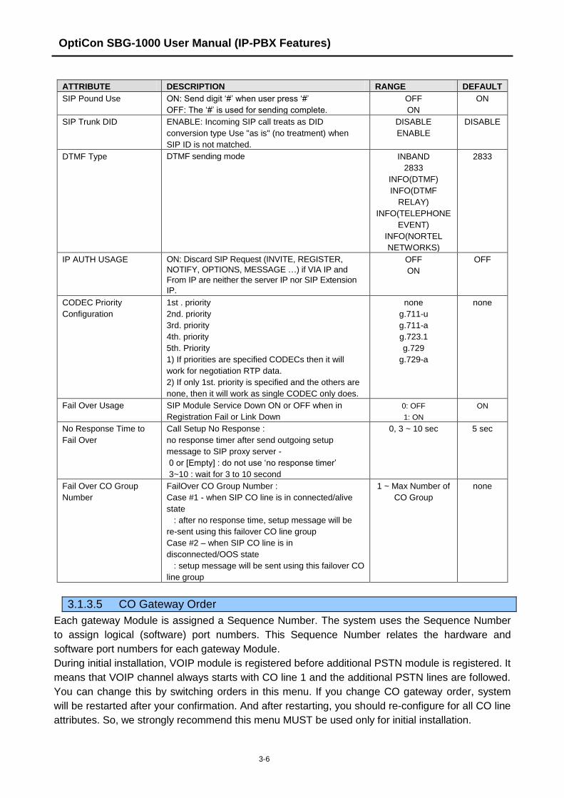
OptiCon SBG-1000 User Manual (IP-PBX Features)
3-6
ATTRIBUTE DESCRIPTION RANGE DEFAULT
SIP Pound Use ON: Send digit „#‟ when user press „#‟
OFF: The „#‟ is used for sending complete.
OFF
ON
ON
SIP Trunk DID ENABLE: Incoming SIP call treats as DID
conversion type Use "as is" (no treatment) when
SIP ID is not matched.
DISABLE
ENABLE
DISABLE
DTMF Type DTMF sending mode INBAND
2833
INFO(DTMF)
INFO(DTMF
RELAY)
INFO(TELEPHONE
EVENT)
INFO(NORTEL
NETWORKS)
2833
IP AUTH USAGE ON: Discard SIP Request (INVITE, REGISTER,
NOTIFY, OPTIONS, MESSAGE …) if VIA IP and
From IP are neither the server IP nor SIP Extension
IP.
OFF
ON
OFF
CODEC Priority
Configuration
1st . priority
2nd. priority
3rd. priority
4th. priority
5th. Priority
1) If priorities are specified CODECs then it will
work for negotiation RTP data.
2) If only 1st. priority is specified and the others are
none, then it will work as single CODEC only does.
none
g.711-u
g.711-a
g.723.1
g.729
g.729-a
none
Fail Over Usage SIP Module Service Down ON or OFF when in
Registration Fail or Link Down
0: OFF
1: ON
ON
No Response Time to
Fail Over
Call Setup No Response :
no response timer after send outgoing setup
message to SIP proxy server -
0 or [Empty] : do not use „no response timer‟
3~10 : wait for 3 to 10 second
0, 3 ~ 10 sec 5 sec
Fail Over CO Group
Number
FailOver CO Group Number :
Case #1 - when SIP CO line is in connected/alive
state
: after no response time, setup message will be
re-sent using this failover CO line group
Case #2 – when SIP CO line is in
disconnected/OOS state
: setup message will be sent using this failover CO
line group
1 ~ Max Number of
CO Group
none
3.1.3.5 CO Gateway Order
Each gateway Module is assigned a Sequence Number. The system uses the Sequence Number
to assign logical (software) port numbers. This Sequence Number relates the hardware and
software port numbers for each gateway Module.
During initial installation, VOIP module is registered before additional PSTN module is registered. It
means that VOIP channel always starts with CO line 1 and the additional PSTN lines are followed.
You can change this by switching orders in this menu. If you change CO gateway order, system
will be restarted after your confirmation. And after restarting, you should re-configure for all CO line
attributes. So, we strongly recommend this menu MUST be used only for initial installation.

OptiCon SBG-1000 User Manual (IP-PBX Features)
3-7
3.1.3.6 Network Basic Attributes
Selecting Network Basic Attributes will display the Network Basic Attributes entry page.
Table 3.5 Network Basic Attributes
ATTRIBUTE DESCRIPTION RANGE DEFAULT
Net Enable Enable Networking function 1:ON
0:OFF
OFF
Net Retry Count Reserved for future usage 00-99
00
Net CNIP Enable The name of calling station is sent to the called system
between OptiCon systems. CNIP is displayed at called
party stations display based on the programming
1:ON
0:OFF
ON
Net CONP Enable Reserved for future usage 1:ON
0:OFF
OFF
Net Signal Method Select the information element type for QSIG
supplementary service message.
1:FAC
0:UUS
FAC
Net Cas Enable It is not used. 1:ON
0:OFF
OFF
Net VPN Enable Reserved for future usage 1:ON
0:OFF
OFF
Net CC Retain Mode It is not used. 1:ON
0:OFF
OFF
3.1.3.7 Network Supplementary Attributes
Selecting Network Supplementary Attributes will display the Network Supplementary Attributes
entry page.
Table 3.6 Network Supplementary Attributes
ATTRIBUTE DESCRIPTION RANGE DEFAULT
Net Transfer Mode Select type for Transfer and Call forward
– Rerouting or Join
1:RERT
0:JOIN
RERT
TCP Port for Blf TCP port for sending BLF message to BLF Manager 0000-9999 9500
UDP Port for Blf UDP port for sending BLF message to BLF Manager 0000-9999 9501
Blf Manager IP IP Address of BLF Server used only when OptiCon is
configured with LDK systems for Voice Networking.
0.0.0.0
Duration of BLF Status Duration of BLF status message sending to BLF
Server
01-99
(100 msec)
10
Multicast IP IP address of Multicast for BLF service 0.0.0.0
Net Trans Rcl timer Network transfer fault recall timer to be used when no
responses from other systems.
001-300
(msec)
10
NET Reroute CO Group The start times for Day, Night and start and end times
for Timed modes are entered for each day of week.
After Timed end time the mode goes to day if time is
less than Night mode.
MFIM &
MFIM100:&
IPECS-
Micro&
IPECS-50
00-20
Other MFIM:
00-72
0

OptiCon SBG-1000 User Manual (IP-PBX Features)
3-8
3.1.3.8 Network CO Line Attributes
Selecting Network CO Line Attributes will display the Network CO Line Group entry page. Enter
the desired data and click Load to display the Network CO Line Group.
Table 3.7 Network CO Line Attributes
ATTRIBUTE DESCRIPTION RANGE DEFAULT
Net CO Group Networking CO group programming for Networking call. 00-24 00
Net CO Line Type Select network CO Line Type 1:NET
0:PSTN
PSTN
3.1.3.9 Network Numbering Plan Table
Selecting Network Numbering Plan Table will display the Network Numbering Plan Table data
entry page.
Table 3.8 Network Numbering Plan Table
ATTRIBUTE DESCRIPTION RANGE DEFAULT
System Usage Select system usage 0:NET
1:PSTN
NET
Numbering Plan Code „*‟ means any digits can be inserted between 0 ~ 9.
The digits followed by „#‟ is a internal station number
16 digits
Numbering Plan CO Group „00‟ means an internal net station number. 00-24
. .
CPN Information Flex 1: ISDN CPN INFORMATION
Flex 2: ( FLEX BTN 1- 4 )
1: 00 CPN INFORMATION 01
2: 00 CPN INFORMATION 02
3: 00 CPN INFORMATION 03
4: 00 CPN INFORMATION 04
16 digits
Alt Speed Bin Alternative Dial Number (System SPD Bin) when the
networking path has a fatal problem.
200-999
or
2000~4999
MFIM (E) IP Address IP Address of destination MFIM/E system only when
OptiCon systems are configured for Voice Networking
0.0.0.0
MFIM(E) Port Port Number of destination system for Networking. 0000-9999 5588
Digit Repeat When the number plan code, see above, is for PSTN
call or transit-call, this number code can be enveloped in
SETUP message or not whether if this field is set or not.
Yes
No
No
Net PSTN Enblock Choose “Transit-out Public Line” as Enblock or Over-lap. Yes
No
No
PSTN CLI Method NET: Send network station number for CLI
PSTN: Send full CLI (eg, 02-450-1000)
NET
PSTN
NET
CO Attendant Code CLI Determine whether if Centralized ATD CLI is sent or not
when slave system makes transit call.
On
Off
Off

OptiCon SBG-1000 User Manual (IP-PBX Features)
3-9
ATTRIBUTE DESCRIPTION RANGE DEFAULT
Firewall Routing Select IP address (Firewall IP address or Non-firewall IP
address).
If the destination system(VOIM) is in same VPN then
Non-firewall IP address should be sent. Otherwise the
firewall IP address should be sent.
ON : Send firewall IP address
OFF : Send Non-firewall(Internal) IP address
On
Off
ON
Transit Out Auth COS When there‟s a transit out call request from slave
system user by seizing CO line, apply COS according to
the authorization code.
Yes
No
No
SMDR Dgt Hide Determine to display dialed digit of transit out call or not
at the slave system ; it can contain authorization code.
Yes
No
No
3.1.3.10 Network Feature Code Table
Selecting Network Feature Code Table returns the data entry page.
Table 3.9 Network Feature Code Table
ATTRIBUTE DESCRIPTION RANGE DEFAULT
Net Feature Code Networking Feature Code programming for Networking
paging call.
16 digits None
Net Feature Destination INT PAGE ZONE : 1-10
ALL CALL PAGE ZONE : INT(1), ALL(3)
3 digits
N/A
3.1.4 Auto Attendant
3.1.4.1 Voice Mail Group Number
A user can program Voice Mail Group Numbers using this page.
3.1.4.2 System Prompt Upload
A user can upload system prompt information using this page; system prompt can be uploaded
with .rom format or .wav format.
1. Prompt Upload menu: upload rom file
??96Wxxxx.rom (?? is nation, i.e., PM, IT, GS, KR, etc.; xxxx indicates the version)
2. Individual Upload menu: upload wave file
1.wav – 999.wav (system prompt should be G.711 u-law wave file format)
3.1.4.3 Announcement Upload & Download
A user can upload and download announcements with .rom format or .wav format.
1. Individual upload/download: upload .wav file
1.wav – 72.wav
2. SysGreeting upload/download: upload .rom file
SGTYPE1.rom

OptiCon SBG-1000 User Manual (IP-PBX Features)
3-10
3.1.5 FAX
FAX Configuration page displays the logical station number of SLT port; a user can change FAX
utilization of each SLT port and also can make T.38 service enabled for FAX.
3.1.6 Numbering Plan
Feature dial codes for the system can be assigned using the System Flexible Number Plan.
Feature codes should be one (1) to four (4) digits in length and must not conflict. For example,
Feature codes 53 and 536 represent a conflict. The system will not update the database until
correct data is entered. The Table provides a brief description for each feature and default codes.
Table 3.10 Flexible Numbering Plan
ATTRIBUTE DESCRIPTION DEFAULT
Attendant Call Dial code to call Main Attendant 0
Alarm Reset Code to reset Alarm contacts 65
Direct Call Pick-Up Dial code to activate Directed Call Pick-up 7
Group Call Pick-Up Group Call Pick-up dial code **
Answering Machine
Emulation
Dial code to assign an Answering Machine Emulation
Flex button
64
Call Forward Code to activate Call Forward. 54
Door Open Dial code to activate Door contact (open door ) #*
Call Coverage Ring Code for Call Coverage button *#
Access Random CO Line Dial code to access the 1st available CO Line in any
accessible group
9
CO Line Group Number Dial code to access a CO Line from a group 801-802
Access Individual CO Line Dial code to access a specific CO Line/IP Channel 8801-8805
Paging Zones Page Zone access dial codes 501-510
All Call Paging All Call Page access dial code 500
Answer Paging (Meet Me) Meet-Me-Page answer dial code 511
Call Park Locations Dial code to place/retrieve a call in system Park Orbit 601-610
Group Pilot Number Station group pilot number 620-631
Do-Not-Disturb (DND) Dial code to activate Do-Not-Disturb 53
DND/FWD Cancel Code to cancel DND/FWD 59
Leave Call-Back Code to activate Message Wait/Call Back 56
Answer Call-Back Code to return Message Wait/Call Back 57
Camp-On Answer Dial code to answer a Camped-On call 66
Last Number Redial (LNR) SLT Last number redial feature access dial code 52
Speed Dial Program SLT Speed Dial programming access code 55
Speed Dial Access SLT Speed Dial access code 58
CO Line System Hold Code to place a CO Line call on System Hold 67
Retrieve Any Of Held CO
Line
Dial code to access last CO Line or IP channel from
Hold
8*
Retrieve Specific Held CO
Line
Dial code to access a specific CO Line/IP channel from
Hold
8#
Company Directory Name Code to check and change recording station subscribe
name of Company Directory feature.
68

OptiCon SBG-1000 User Manual (IP-PBX Features)
3-11
3.2 VOICE CONFIGURATION
In this section, user can see or change database for Station, CO Line, System, Station Group
(shown).
3.2.1 Station Data
3.2.1.1 Common Attributes
The Common Attributes Table defines features and functions available to the station.
Table 3.11 Common Attributes
ATTRIBUTE DESCRIPTION RANGE DEFAULT
CLI Table Index Default outgoing CLI Table Index. 0-5 1
CLIR Service CLIR (Calling Line Identification Restriction), an
ISDN service, removes the calling party ID sent
from the ISDN to the called party with a RESTRICT
instruction in the SETUP message. If enabled, the
system will send the RESTRICT instruction to the
CO when an outgoing ISDN call is placed.
ON
OFF
OFF
COLR Service COLR (Connected Line Id Restriction), an ISDN
service, removes the connected party ID sent from
the ISDN to the calling party with a RESTRICT
instruction in the CONNECT message. If enabled,
the system will send the restrict instruction to the
CO when the station places an ISDN call.
ON
OFF
OFF
CO Group Access Stations can be allowed or denied access to CO
group.
1, 2, 3, 4, 5 1, 2, 3, 4, 5
Station Forward No Answer
Timer
This timer determines the duration the station will
ring prior to Ring-No-Answer Forward. This setting
affects both manual and Preset Call Forward and
overrides the Call Forward No Answer Timer in
System Call Feature Timer
000-600
seconds
000

OptiCon SBG-1000 User Manual (IP-PBX Features)
3-12
ATTRIBUTE DESCRIPTION RANGE DEFAULT
Active in OOS If a station is Out-of-Service and has previously
forwarded calls, the system will forward the calls if
enabled.
ON
OFF
OFF
DID Call Wait When a busy station receives an external call, the
call may queue to the station instead of receiving a
busy tone. With Call Wait, the caller will hear a
Ring-back tone and the CO line LED flashes.
ON
OFF
ON
Voice Over Enables use of Voice Over by station ENABLE
DISABLE
DISABLE
Prime Line Enables Delayed Prime Line (Idle Line) activation,
see Idle Line Selection.
HOT
WARM
WARM
Idle Line Selection When a station goes to an off-hook condition (lifts
handset or presses [speaker] button), the system
normally provides intercom dial tone. In place of
dial tone, the station can be programmed to
activate Flex button as if pressed, access a CO
Line, access CO Group or call a Station
No Selection
Flex Button
(1-24)
CO Line
(1-8)
CO Group
(1-5)
Station
No Selection
CO PGM A station can be permitted to change the CO Line
numbers (ports) associated with a CO Line button.
Disable
Enable
Disable
Automatic Talk Recording
Dest.
When Auto Call recording is defined for a station,
the recording Phontage station number or station
group number is defined here.
Station
Station Grp
Headset Ring Selects device to receive incoming ring signals
(Speaker, Headset or Both).
Speaker
Headset
Both
Speaker
Headset or Speaker Mode Select Speaker or Headset mode for the IP Phone. Headset
Speaker
Speaker
Send SLT CLI Info When allowed, the system sends CLI information to
the SLT
ON
OFF
ON
3.2.1.2 Flex Buttons
Each Flex button on a LIP Phone can be assigned a function (TYPE) as listed:
Empty
Number Plan
User Program code
Station Speed Dial
System Speed Dial
After selecting the Type for a button, enter the appropriate value (Where applicable).
3.2.1.3 Paging Access
Each LIP Phone is assigned to be able to receive announcements from each Page Zone. A station
can be assigned to any, all, or no page zones. The OptiCon SBG-1000 system supports up to 10
Internal Page Zones. By default, all stations are assigned to Zone 1.
NOTE: A station not assigned to any page zone will not receive any page announcements.

OptiCon SBG-1000 User Manual (IP-PBX Features)
3-13
3.2.1.4 Executive / Secretary Table
Stations can be paired as Executive/Secretary pairs so that when the Executive enters DND, the
call to the Executive is automatically routed to the Secretary. Up to 10 Executive/Secretary pairs
can be defined. An Executive may have multiple Secretaries and a Secretary can be assigned to
multiple Executives. A Secretary of one pair may be the Executive of another however,
assignments that form a loop-back are not allowed.
The “CO Call to Sec” option will route all CO calls to the Executive to the defined Secretary„s
station regardless of the Executive„s station status. The “Call Exec if Sec DND” option will route
Executive calls back to the Executive if the Secretary is in DND. The Exec Grade permits higher
grade Executives to override the Executive/Secretary Forward feature to call a lower grade
Executive (Korea only). The highest grade is 1 and the lowest grade is 12. The “ICM Call to Sec”
option will route all internal calls to the Executive(except for calls from higher or same grade
executive) to the defined Secretary„s station regardless of the Executive„s station status. The “Sec
Auto Ans” option will make the Secretary answered forcedly with speaker phone as soon as the
Executive calls to the Secretary.
3.2.1.5 Mobile Extension Table
Selecting Mobile Extension Table will display the Mobile Extension data entry page.
A mobile phone can be used in conjunction with an LIP Phone. The Mobile phone can access
system resources available to the user‟s wired phone and will receive ring for incoming OptiCon
SBG-1000 calls. The user may be allowed to enable the Mobile extension and define the mobile
number. The system can be defined to employ a specific CO Line Group to place calls to the
Mobile phone. In addition, the mobile phone can be assigned to receive hunt group calls to the
primary extension. Also, parameters for notification of new VSF voice mails can be defined.
Table 3.12 Mobile Extension Table
ATTRIBUTE DESCRIPTION RANGE DEFAULT
Internal Access The user may be allowed to access internal call from the mobile
extension.
Disable/Enable Disable
Usage Mobile extension feature can be enabled and Fail Over to Mobile
extension can be included.
Disable
Mobile Ext
Fail Over
Disable
Hunt Enable When the paired station is a member of a hunt group (Circular or
Terminal), group calls can be sent to the active mobile extension.
Disable
Enable
Disable
VSF/VMIM
Notify
Enables outbound notification by the system when the VSF has
unheard messages.
Not Use
Use
Not Use
Notify Retry Defines the number of attempts the system will make to complete
a notification when receiving busy/no-answer.
1 – 9 Times 3 Times
Retry Interval Defines the time between notification attempts. If a notification
fails, the system will retry after the timer expires.
1 – 3 Minute 3 Minute
Notify CLI When the system sends CLI to the mobile extension, the CLI can be
either the original caller‟s CLI or the CLI of station.
Caller
My Ext.
Caller
Call Back If it is set to “ON”, incoming mobile extension call will be released
before answered and system places a call to mobile extension.
After mobile extension answers, the dial tone is provided and
mobile extension can make internal or external call.
OFF
ON
OFF

OptiCon SBG-1000 User Manual (IP-PBX Features)
3-14
ATTRIBUTE DESCRIPTION RANGE DEFAULT
Delay Timer Mobile extension call will be placed after delay time. 0 ~ 255 0
CO Group CO group used to call the mobile extension.
0 ~ 5 01
Telephone
Number
Telephone number or CLI of the Mobile extension. Not assigned
CLI Number When the mobile Telephone number and CLI do not match, the
CLI entered here is used to authorize incoming calls from the
mobile.
Not assigned
3.2.1.1 Station Voice Mail Attributes
Various Station Voice Mail attributes can be configured in this menu including voice mail to e-mail
notification and voice mail backup.
Some of these options can be worked only when Station VM Feature Usage is set to “ON”.
Table 3.13 Station Voice Mail Attributes
ATTRIBUTE DESCRIPTION RANGE DEFAULT
VM Message No Number of Voice Mail that is left to the station.
VM COS A station has Voice Mail COS from 1 to 5. By COS grade, Voice
Mail COS attribute can be assigned. 1-5 1
Administrator
Mailbox
Administrator Voice Mail feature can be activated. Disable
Enable Disable
Announce Only
Mailbox
If this option is set to ON, caller cannot leave a message to the
station, only can hear the station„s user greeting.
Disable
Enable Disable
Announce Only
Option
When Announcement Only Mailbox is ON, after hearing a
station„s user greeting, next step is decided by this option – go to
previous menu or call is disconnected.
Previous Menu
Hang Up
Previous
menu
Company
Directory – First
Name
First Name of Company Directory is assigned.
Max 12 Char N/A
Company
Directory – Last
Name
Last Name of Company Directory is assigned.
Max 12 Char N/A
Cascade
Mailbox
A destination station number of message cascading feature is
assigned. Station No N/A
Cascade Type
Message cascading type is programmed. Disable
Copy Immediate
Copy Urgent
Move Immediate
Move Urgent
Disable
Message
RW/FF Time
Rewind / Fast Forward time of left message is defined . 03 - 99 04
VSF MSG –
SMTP Mail
Server Address
The VSF includes notification of new messages to the user„s voice
mail. This field defines the user„s e-mail mail server for the
notification.
IP v4 address
Or Mail server
name
VSF MSG –
User Mail
Address
The VSF includes notification of new messages to the user„s voice
mail. This field defines the e-mail address to notify when a new
message is received at the VSF or VMIM.
e-mail address
VSF MSG –
SMTP Mail
Server ID
The VSF includes notification of new messages to the user„s voice
mail. This field defines the e-mail address to notify when a new
message is received at the VSF or VMIM.

OptiCon SBG-1000 User Manual (IP-PBX Features)
3-15
ATTRIBUTE DESCRIPTION RANGE DEFAULT
VSF MSG –
SMTP Mail
Server
Password
Unified Mail server password
VSF MSG –
Attached
Message
When e-mail notification of a new VSF message is enabled, the e-
mail may include the voice mail as a wav file attachment.
OFF
ON
ON
VSF MSG –
Date/Time
When ON, play the data/time stamp of VSF message OFF
ON
ON
VSF MSG –
Delete Message
After sending VSF mail, attached VSF message is deleted, when
this option is ON.
OFF
ON
OFF
VSF MSG –
SMTP Security
Choose SMTP Security. No Security
SSL
TLS
No Security
VSF MSG –
SMTP Port
Choose SMTP Port 1 - 65535 25
VSF MSG –
Sender Mail
Address
Program VSF mail Sender mail Address. e-mail address
VSF Backup
Delete Option
A Phontage may monitor voice messages for another station as a
backup. The Phontage will include the message count for the
station in the Voice message count. When enabled here, the
Phontage may delete messages for the station.
OFF
ON
OFF
VSF Backup
Station
A Phontage may monitor voice messages for another station as a
backup. The Phontage will include the message count for the
station in the Voice message count. This field defines the
Phontage station number that will be used as the VSF back up.
station
VSF Backup
Prompt
A Phontage may backup VSF Prompts. OFF
ON
OFF
3.2.1.2 Preset Call Forward
Stations can be programmed so that incoming CO and Intercom calls are forwarded to a preset
station or station group. This allows an external call or internal call to initially ring at a station and
forward to a pre-determined destination. Preset Call Forward can be separately assigned
Unconditional, Internal Busy, Internal No Answer, External Busy or External No Answer preset
forwarding to any station, hunt group or system speed dial bin (off-net). As a default, no Preset Call
Forward is assigned.
For Transfer Mail-Box, enter the Station Group number of the Voice Mail group; this will permit LIP
Phone users to forward calls directly to the desired user‟s Voice Mail-Box.
3.2.1.3 Individual Speed Dial
Each user can store commonly dialed numbers for easy access using Individual Speed Dial bins.
Each station has access to 20 Speed Dial numbers; each Speed Dial number can be up to 23
characters in length and may include special instruction codes.
Special instruction codes available are:
„*‟ as 1st digit Activate Display Security, do not display number.

OptiCon SBG-1000 User Manual (IP-PBX Features)
3-16
LIP Phone users may assign a Flex button for One-Touch access to a specific Speed Dial bin. In
addition, the LIP Phone user may assign a Telephone number directly to a Flex button. In this
case, the telephone number is allocated to the highest numbered available Individual Speed Dial
bin.
Stored speed dial number should not include CO access code.
3.2.1.4 Authorization Code & COS
Authorization codes (up to 12 digits) are used to control access to system resources and facilities.
Voice Mail-box and certain Call Forward types may require the input of a valid Authorization code.
The Station entries are associated with individual stations.
All stations are assigned a Class-of-Service (COS), which determines the user‟s ability to dial
certain types of calls (refer to Station COS Table). Separate COS assignments are made for Day,
Timed and Night Mode operation. As a default, all stations are assigned with a Station COS of 1
for all modes (No restrictions).
Table 3.14 STATION COS
STATION COS RESTRICTIONS
1 No restrictions are placed on dialing from the station.
2 The assignments in Exception Table A are monitored for allow and deny numbers.
3 The assignments in Exception Table B are monitored for allow and deny numbers.
4 The assignments in both Exception Tables A & B are monitored for allow and deny
numbers.
5 The leading digit cannot be a Long Distance code and assignments in Exception Table C
apply.
6 Number of digits cannot exceed LD digit count and assignments in Exception Table C apply.
7 Intercom and Emergency number calls are allowed. Incoming and transferred calls are
allowed.
A station must be allowed Off Net Fwd to forward external incoming calls outside the system or
establish a CO-to-CO connection.
If Station Account is set to “ON”, the station user must enter an authorization code to access CO
lines.
3.2.1.5 Station Hold Music
OptiCon SBG-1000 supports two types of Hold Music for Intercom calls. One type of MOH is Hold
Tone, and the other type is Record Play. A VSF announcement may be recorded and played as
MOH to the connected caller.
3.2.2 CO Line Data
3.2.2.1 Call Routing by Line
This page is enabled only when OptiCon SBG-1000 has FXO ports (CSIU, CIU1, CIU2 or CIU4
option board is installed).

OptiCon SBG-1000 User Manual (IP-PBX Features)
3-17
Each CO line is assigned to signal a station or group for an incoming call (Ring). Separate ring
assignments are made for Day, Night, and Timed Ring modes. When assigned to ring to a VSF
announcement, the call can be dropped automatically after the assigned announcement by
checking the “Auto Drop”.
When CO Lines are programmed to Ring to a VSF Group as an Automated Attendant, the Ring
signal can be on an immediate or delayed basis allowing other stations/groups to be assigned Ring
and answer prior to signaling the AA. The delay is defined in seconds from 00 to 30.
When a call is received, the system may use the ICLID (Incoming Caller ID) to route the call. The
system will delay routing a call for ICLID ring timer while awaiting ICLID. If ICLID ring timer is 0,
ICLID routing is disabled.
3.2.2.2 Call Routing by Called Number
This page is enabled only when OptiCon SBG-1000 has BRI port (BRIU or BRIU2 option board is
installed).
These characteristics are required for proper operation of the system and BRI incoming call
destination selection.
Table 3.15 Call Routing by Called Number
ATTRIBUTE DESCRIPTION RANGE DEFAULT
Name of Called Number Name of Called Number
Route To (Day-Mode Period) Call routing destination in Day-Mode Station
Group 631
Route To (Night-Mode
Period)
Call routing destination in Night-Mode Station
Group 631
Route To (Timed-Mode
Period)
Call routing destination in Timed-Mode Station
Group 631
See Caller Number First Call is routing according to the „Call Routing by
Caller Number‟ if caller number is matched
ON/OFF OFF
3.2.2.3 Call Routing by Caller Number
The system can employ Incoming Calling Line ID (ICLID) to determine the routing of incoming
external calls. The system will compare the received ICLID, and if a match is found, will route the
call to the destination defined in the Ring Assignment Table index.
Table 3.16 Call Routing by Caller Number
ATTRIBUTE DESCRIPTION RANGE DEFAULT
Caller Number ICLID (Incoming Caller ID) to match for the index. If
the Caller ID matches the Table entry, the index is
used to select the route.
23 Digits None
Caller Name ICLID name that is sent by the system to the
destination for the ICLID routed call.
12.
Character
None
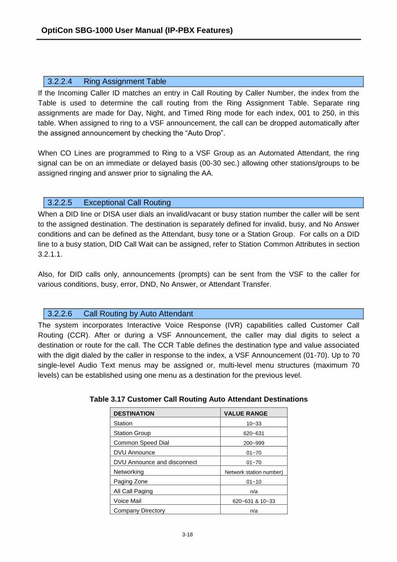
OptiCon SBG-1000 User Manual (IP-PBX Features)
3-18
3.2.2.4 Ring Assignment Table
If the Incoming Caller ID matches an entry in Call Routing by Caller Number, the index from the
Table is used to determine the call routing from the Ring Assignment Table. Separate ring
assignments are made for Day, Night, and Timed Ring mode for each index, 001 to 250, in this
table. When assigned to ring to a VSF announcement, the call can be dropped automatically after
the assigned announcement by checking the “Auto Drop”.
When CO Lines are programmed to Ring to a VSF Group as an Automated Attendant, the ring
signal can be on an immediate or delayed basis (00-30 sec.) allowing other stations/groups to be
assigned ringing and answer prior to signaling the AA.
3.2.2.5 Exceptional Call Routing
When a DID line or DISA user dials an invalid/vacant or busy station number the caller will be sent
to the assigned destination. The destination is separately defined for invalid, busy, and No Answer
conditions and can be defined as the Attendant, busy tone or a Station Group. For calls on a DID
line to a busy station, DID Call Wait can be assigned, refer to Station Common Attributes in section
3.2.1.1.
Also, for DID calls only, announcements (prompts) can be sent from the VSF to the caller for
various conditions, busy, error, DND, No Answer, or Attendant Transfer.
3.2.2.6 Call Routing by Auto Attendant
The system incorporates Interactive Voice Response (IVR) capabilities called Customer Call
Routing (CCR). After or during a VSF Announcement, the caller may dial digits to select a
destination or route for the call. The CCR Table defines the destination type and value associated
with the digit dialed by the caller in response to the index, a VSF Announcement (01-70). Up to 70
single-level Audio Text menus may be assigned or, multi-level menu structures (maximum 70
levels) can be established using one menu as a destination for the previous level.
Table 3.17 Customer Call Routing Auto Attendant Destinations
DESTINATION VALUE RANGE
Station 10~33
Station Group 620~631
Common Speed Dial 200~999
DVU Announce 01~70
DVU Announce and disconnect 01~70
Networking Network station number)
Paging Zone 01~10
All Call Paging n/a
Voice Mail 620~631 & 10~33
Company Directory n/a

OptiCon SBG-1000 User Manual (IP-PBX Features)
3-19
DESTINATION VALUE RANGE
Record VM Greeting n/a
3.2.2.7 Common Speed Dial
Commonly dialed numbers can be stored by the Attendant or the Administrator in Web Admin. for
easy access by stations allowed use of Common Speed Dial bins. Up to 800 Common Speed Dial
numbers are available; each Speed Dial number can be up to 23 characters in length and may
include special instruction codes.
Special instruction codes available are:
„*‟ as 1st digit Activate Display Security.
LIP Phone users may assign a Flex button for One-Touch access to a specific Common Speed
Dial bin.
Stored speed dial number should not include CO access code.
3.2.2.8 CO Hold Music
OptiCon SBG-1000 supports two type of Hold Music for CO Line calls. One type of MOH is Hold
Tone, and the other type is Record Play. A VSF announcement may be recorded and played as
MOH to the connected caller.
3.2.3 System Data
3.2.3.1 System Attributes
The default system codec is defined as G.711. The system codec will be used on all internal
communications as well as for other remote devices.
More system attributes are described in the following.
Table 3.18 System Attributes
ATTRIBUTE DESCRIPTION RANGE DEFAULT
DISA Retry Count A DISA user is allowed to retry erroneous
authentication code entries. This entry sets the
number of retries before the system disconnects.
1~9 3
Old Auth Code Usage System Authorization codes are entered by the user
as “*” when this entry is set to ON or “*”+ the Auth
code index when this entry is set to OFF.
OFF
ON
ON
End code(#) usage in
System Auth Code
If this option is set to ON, End code(#) must be
entered when system Auth code is entered.
OFF
ON
OFF
Station VM Feature Usage If this option is set to ON, Station VM feature can be
used.
OFF
ON
OFF
WAN Fault Alarm Disable The WAN Fault Alarm to Attendant can be
disabled. It will be useful to the site which does not
use WAN port.
OFF
ON
OFF
Emergency Call ATD Notify Provide notification to attendant when user dial
emergency number
DISABLE
ENABLE
ENABLE
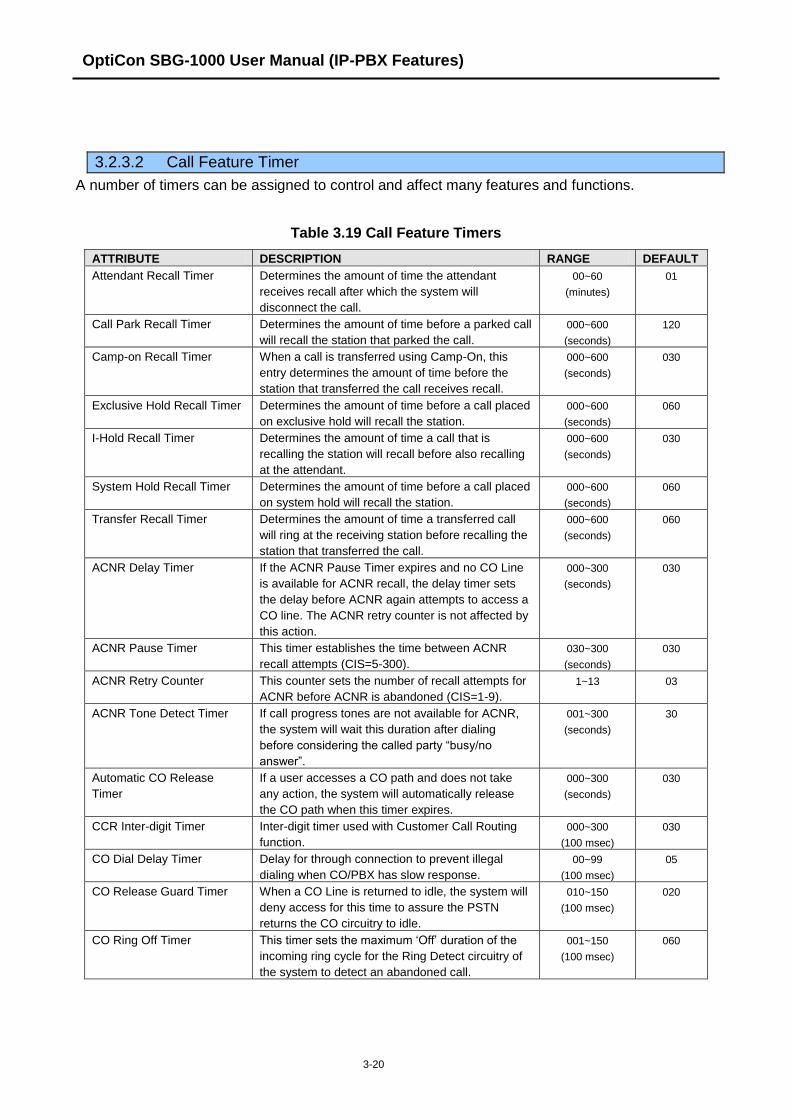
OptiCon SBG-1000 User Manual (IP-PBX Features)
3-20
3.2.3.2 Call Feature Timer
A number of timers can be assigned to control and affect many features and functions.
Table 3.19 Call Feature Timers
ATTRIBUTE DESCRIPTION RANGE DEFAULT
Attendant Recall Timer Determines the amount of time the attendant
receives recall after which the system will
disconnect the call.
00~60
(minutes)
01
Call Park Recall Timer Determines the amount of time before a parked call
will recall the station that parked the call.
000~600
(seconds)
120
Camp-on Recall Timer When a call is transferred using Camp-On, this
entry determines the amount of time before the
station that transferred the call receives recall.
000~600
(seconds)
030
Exclusive Hold Recall Timer Determines the amount of time before a call placed
on exclusive hold will recall the station.
000~600
(seconds)
060
I-Hold Recall Timer Determines the amount of time a call that is
recalling the station will recall before also recalling
at the attendant.
000~600
(seconds)
030
System Hold Recall Timer Determines the amount of time before a call placed
on system hold will recall the station.
000~600
(seconds)
060
Transfer Recall Timer Determines the amount of time a transferred call
will ring at the receiving station before recalling the
station that transferred the call.
000~600
(seconds)
060
ACNR Delay Timer If the ACNR Pause Timer expires and no CO Line
is available for ACNR recall, the delay timer sets
the delay before ACNR again attempts to access a
CO line. The ACNR retry counter is not affected by
this action.
000~300
(seconds)
030
ACNR Pause Timer This timer establishes the time between ACNR
recall attempts (CIS=5-300).
030~300
(seconds)
030
ACNR Retry Counter This counter sets the number of recall attempts for
ACNR before ACNR is abandoned (CIS=1-9).
1~13
03
ACNR Tone Detect Timer If call progress tones are not available for ACNR,
the system will wait this duration after dialing
before considering the called party “busy/no
answer”.
001~300
(seconds)
30
Automatic CO Release
Timer
If a user accesses a CO path and does not take
any action, the system will automatically release
the CO path when this timer expires.
000~300
(seconds)
030
CCR Inter-digit Timer Inter-digit timer used with Customer Call Routing
function.
000~300
(100 msec)
030
CO Dial Delay Timer Delay for through connection to prevent illegal
dialing when CO/PBX has slow response.
00~99
(100 msec)
05
CO Release Guard Timer When a CO Line is returned to idle, the system will
deny access for this time to assure the PSTN
returns the CO circuitry to idle.
010~150
(100 msec)
020
CO Ring Off Timer This timer sets the maximum „Off‟ duration of the
incoming ring cycle for the Ring Detect circuitry of
the system to detect an abandoned call.
001~150
(100 msec)
060
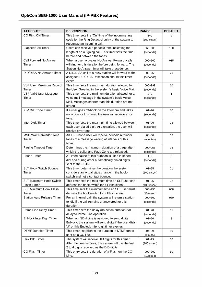
OptiCon SBG-1000 User Manual (IP-PBX Features)
3-21
ATTRIBUTE DESCRIPTION RANGE DEFAULT
CO Ring ON Timer This timer sets the „On‟ time of the incoming ring
cycle for the Ring Detect circuitry of the system to
recognize an incoming call.
1~9
(100 msec.)
2
Elapsed Call Timer Users can receive a periodic tone indicating the
length of an outgoing call. This timer sets the time
before and between the tones.
060~900
(seconds)
180
Call Forward No Answer
Timer
When a user activates No-Answer Forward, calls
will ring for this duration before being forward. The
Station No Answer timer will take precedence.
000~600
(seconds)
015
DID/DISA No Answer Timer A DID/DISA call to a busy station will forward to the
assigned DID/DISA Destination should this timer
expire.
000~255
(seconds)
20
VSF User Maximum Record
Timer
This timer sets the maximum duration allowed for
the User Greeting in the system‟s basic Voice Mail.
000~999
(seconds)
60
VSF Valid User Message
Timer
This timer sets the minimum duration allowed for a
voice mail message in the system‟s basic Voice
Mail. Messages shorter than this duration are not
stored.
0~9
(seconds)
1
ICM Dial Tone Timer If a user goes off-hook on the Intercom and takes
no action for this timer, the user will receive error
tone.
01~20
(seconds)
10
Inter Digit Timer This timer sets the maximum time allowed between
each user-dialed digit. At expiration, the user will
receive error-tone.
01~20
(seconds)
03
MSG Wait Reminder Tone
Timer
An LIP Phone user will receive periodic reminder
tones of a message waiting at intervals of this
timer.
00~60
(minutes)
00
Paging Timeout Timer Determines the maximum duration of a page after
which the caller and Page Zone are released.
000~255
(seconds)
15
Pause Timer A Timed pause of this duration is used in speed
dial and during other automatically dialed digits
sent to the PSTN.
1~9
(seconds)
3
SLT Hook Switch Bounce
Timer
This timer determines the duration the system
considers an actual state change in the hook-
switch and not a contact bounce.
01~25
(100 msec.)
01
SLT Maximum Hook Switch
Flash Timer
This timer sets the maximum time an SLT user can
depress the hook-switch for a Flash signal.
01~25
(100 msec.)
02
SLT Minimum Hook Flash
Timer
This time sets the minimum time an SLT user must
depress the hook-switch for a Flash signal.
000~250
(10 msec.)
008
Station Auto Release Timer For an internal call, the system will return a station
to idle if the call remains unanswered for this
duration.
000~300
(seconds)
060
Prime Line Delay Timer This timer sets the delay (no action duration) for
delayed Prime Line operation.
01~20
(seconds)
05
Enblock Inter Digit Timer When an ISDN Line is assigned to send digits
Enblock, the system will send digits if the user dials
“#” or this Enblock inter-digit timer expires.
01~20
(seconds)
3
DTMF Duration Timer This timer establishes the duration of DTMF tones
sent on a CO line.
04~99
(10 msec.)
10
Flex DID Timer The system will receive DID digits for this timer.
After the timer expires, the system will use the last
2 to 4 digits received as the DID digits.
01~99
(100 msec.)
30
CO Flash Timer This entry sets the duration of a Flash on the CO
Line.
000~300
(10msec)
50

OptiCon SBG-1000 User Manual (IP-PBX Features)
3-22
ATTRIBUTE DESCRIPTION RANGE DEFAULT
SIP Station Registration
Timer
Shorter time will make more traffic. More than 10
minute recommended. 0 means registration timer is
disabled.
0, 30~3600
(seconds)
3600
Record Warning Repeat
Timer
If record warning tone is set and this timer is set
greater than 1, it works periodically when it‟s
recorded.
00~999
(seconds)
0
3.2.3.3 Day/Night/Timed Schedule
The system can be programmed to automatically select the Ring and COS mode based on time of
day and day of week. Three Ring & COS modes are available: Day, Timed and Night. The Ring
assignments are as defined in the Call Routing by Line and Ring Assignments Table. COS
assignments are made according to Authorization Code & COS.
The start times for Day, Night and start and end times for Timed modes are programmed for each
day of the week. After Timed end time the mode goes to Day if time is less than Night mode. The
Attendant can override the Automatic selection and select the desired Mode (Day, Night, or Timed)
manually.
3.2.3.4 Toll Exception Table
There are three Toll Restriction Tables arranged in pairs. Each pair consists of an Allow Table and
a Deny Table. Each Toll Exception Table permits entry of 50 Allow codes and 50 Deny codes.
Each code can contain up to 20 digits including digits 0-9, “#” as a wild card (any digit) and “*” as
the end of entry mark.
Based on Table entries, stations or DISA users are allowed or denied dialing specified numbers.
The following rules apply to establish restrictions based on the Table entries:
If entries are only made in the Allow Table, only those numbers entered can be dialed, all
other dialed numbers will be restricted.
If entries are only made in the Deny Table, only those numbers entered will be restricted
and all other numbers can be dialed.
When there are entries in both the Allow and Deny Table pair, if the number is in the Deny
Table, the number will be restricted otherwise the number can be dialed without restriction.
3.2.3.5 Emergency Dialing
The Emergency Code Table is used to identify emergency numbers, which when dialed, will
override all COS dialing restrictions. An Emergency Code number may be up to fifteen (15) digits
in length.
3.2.3.6 SMDR Attributes
Station Message Detail Recording (SMDR), which is output over TCP channel, contains details on
both incoming and outgoing calls. Various SMDR attributes can be assigned including; output
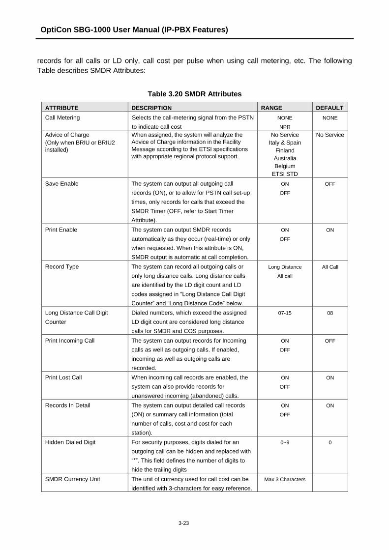
OptiCon SBG-1000 User Manual (IP-PBX Features)
3-23
records for all calls or LD only, call cost per pulse when using call metering, etc. The following
Table describes SMDR Attributes:
Table 3.20 SMDR Attributes
ATTRIBUTE DESCRIPTION RANGE DEFAULT
Call Metering Selects the call-metering signal from the PSTN
to indicate call cost
NONE
NPR
NONE
Advice of Charge
(Only when BRIU or BRIU2
installed)
When assigned, the system will analyze the
Advice of Charge information in the Facility
Message according to the ETSI specifications
with appropriate regional protocol support.
No Service
Italy & Spain
Finland
Australia
Belgium
ETSI STD
No Service
Save Enable The system can output all outgoing call
records (ON), or to allow for PSTN call set-up
times, only records for calls that exceed the
SMDR Timer (OFF, refer to Start Timer
Attribute).
ON
OFF
OFF
Print Enable The system can output SMDR records
automatically as they occur (real-time) or only
when requested. When this attribute is ON,
SMDR output is automatic at call completion.
ON
OFF
ON
Record Type The system can record all outgoing calls or
only long distance calls. Long distance calls
are identified by the LD digit count and LD
codes assigned in “Long Distance Call Digit
Counter” and “Long Distance Code” below.
Long Distance
All call
All Call
Long Distance Call Digit
Counter
Dialed numbers, which exceed the assigned
LD digit count are considered long distance
calls for SMDR and COS purposes.
07-15 08
Print Incoming Call The system can output records for Incoming
calls as well as outgoing calls. If enabled,
incoming as well as outgoing calls are
recorded.
ON
OFF
OFF
Print Lost Call When incoming call records are enabled, the
system can also provide records for
unanswered incoming (abandoned) calls.
ON
OFF
ON
Records In Detail The system can output detailed call records
(ON) or summary call information (total
number of calls, cost and cost for each
station).
ON
OFF
ON
Hidden Dialed Digit For security purposes, digits dialed for an
outgoing call can be hidden and replaced with
“*”. This field defines the number of digits to
hide the trailing digits
0~9 0
SMDR Currency Unit The unit of currency used for call cost can be
identified with 3-characters for easy reference.
Max 3 Characters

OptiCon SBG-1000 User Manual (IP-PBX Features)
3-24
ATTRIBUTE DESCRIPTION RANGE DEFAULT
SMDR Cost Per Metering
Pulse
When call metering is provided by the PSTN,
the cost per metering pulse can be assigned.
6-digits 000000
SMDR Decimal Position This value determines the position of the
decimal in the Cost per Pulse entry above,
starting from the right most digit.
0~5 2
Record Start Guaranteed
Time
To allow for call set-up times through the
PSTN, a “Valid call timer” can be set.
000~250
(msec)
000
Long Distance Code For SMDR and COS purposes, five (5) Long
Distance codes of up to two (2) digits each can
be assigned. If dialed as the 1st digits, the call
is considered an LD call.
5 two digit LD
codes, use * as wild
card (any digit)
SMDR CLI or Ring Service I For incoming calls, the system will send the
defined data item for “Field I”. The data item
may be CLI, CPN or Ring Service Time. Note
the User dialed number is always provided for
an outgoing call.
RING
CLI
CPN
RING
SMDR Ring/CLI/CPN Service
II
For incoming calls, the system will send the
defined data item for “Field II”. The data item
may be CLI, CPN or Ring Service Time.
RING
CLI
CPN
NONE
NONE
Print MSN Print MSN number Information in SMDR
Record
ON
OFF
OFF
Print Order No Print record number as part of SMDR output,
will reset to 1 when SMDR capacity is reached
or SMDR Mail Auto Delete Set above is
enabled.
ON
OFF
OFF
LCD Display Priority Caller ID can be overwritten on Duration or
Cost LCD column or not.
Caller ID
Duration / Cost
Caller ID
SMDR ICM Save When enabled, intercom call data is stored as
part of the SMDR data.
ON
OFF
OFF
SMDR ICM Print When enabled, intercom call data is printed as
part of the On-line SMDR.
ON
OFF
OFF
SMDR Disconnect Cause When enabled, the disconnect cause is stored
in Off-line SMDR data and printed as parted of
the On-line SMDR.
ON
OFF
OFF
SMTP Mail Server Address SMTP Mail server address to send e-mail
SMDR reports.
100 Characters
SMTP Mail Server ID This field defines the user‟s ID for SMTP Mail
server. If user‟s ID and password is assigned,
SMTP Mail server will check the validation of
user ID and password.
Max 40 Characters.
SMTP Mail Server Password This field defines the user‟s password for
SMTP Mail server. If user‟s ID and password is
assigned, SMTP Mail server will check the
validation of user ID and password.
Max 20 Characters.
SMDR Sender Mail Address Sender e-mail address to send the SMDR e-
mail reports.
40 Characters -

OptiCon SBG-1000 User Manual (IP-PBX Features)
3-25
ATTRIBUTE DESCRIPTION RANGE DEFAULT
SMDR Receiver Mail Address Receiver e-mail address to receive the SMDR
e-mail reports.
40 Characters
SMDR Mail Send Weekly Set Sets day of week to send SMDR data weekly
(0 for no weekly data, 1-7 for Monday through
Sunday).
N/A
day
N/A
SMDR Mail Send Daily Set Sets time-of-day for SMDR data sent on a
daily basis (00 for no daily records, 01-23 for
hour of the day).
00~23 00
SMDR Mail Auto Send Set If the SMDR buffer is full, the system will
automatically send a notification e-mail.
ON
OFF
OFF
SMDR Mail Auto Delete Set Delete SMDR records after sending e-mail. ON
OFF
OFF
SMTP Security Choose SMTP Security No Security
SSL
TLS
No Security
SMTP Port Choose SMTP Port 1 ~ 65535 25
3.2.3.7 International Call
International call can be restricted by prefix matching. International call prefix, all international call
restriction and CO-CO international call restriction can be programmed in this admin. The following
Table describes International Call:
Table 3.21 International Call
ATTRIBUTE DESCRIPTION RANGE DEFAULT
International Prefix International prefix is used for classification of
international call.
Max 2 digits 00
All International call All outgoing international call can be restricted
by this attribute.
Enable
Disable
Enable
CO-CO International call Transfer or forward to International call can be
restricted by this attribute.
Enable
Disable
Disable
3.2.3.8 Alarm Attribute
Alarm can be set by this attribute.
Table 3.22 Alarm Attribute
ATTRIBUTE DESCRIPTION RANGE DEFAULT
Alarm Enable Alarm Enable ON/OFF ON
Alarm Contact Type Close/Open Close
Alarm Mode You can choice Alarm or Door Bell. Alarm/Door Bell Alarm
Alarm Signal Mode How many times repeat? Repeat/Once Repeat

OptiCon SBG-1000 User Manual (IP-PBX Features)
3-26
3.2.4 Station Group Data
Stations can be grouped so that incoming calls will search (hunt) for an idle station in the group.
The OptiCon SBG-1000 System supports 7 different hunt processes: Circular, Terminal, Ring,
Pick-Up, VSF-Voice Mail, IPCR, Networking Voice Mail.
The Station Group capacities for the OptiCon SBG-1000 systems are shown in the Table:
Table 3.23 Station Group Data
ITEM CAPACITY
Number of Groups 12
Stations in a Group 24
Certain types of groups can incorporate announcements, which are given to the calling party. The
system‟s VSF can store up to 70 announcements for use with Station Groups.
NOTE: A station can belong to multiple groups if the groups are of the same type. When a Station
Group is assigned to a group type, the group attributes revert to the default values.
3.2.4.1 Station Group Assignment
Under Station Group Assignments the type, members and Pick-Up attributes are assigned.
Table 3.24 Station Group Assignment
ATTRIBUTE DESCRIPTION RANGE DEFAULT
Group Type Defines the type of station group. N/A
Circular
Terminal
Ring
Pick-Up
VSF-VM
IPCR
NET-VM
N/A
Pick-up Attribute Stations can pick-up group calls ringing at other stations in
the group. This does not apply to VSF groups.
OFF
ON
OFF
Member Assign stations as members of a station group. -
3.2.4.2 Station Group Attributes
Each type of group has a different set of available attributes relating to announcements, timers,
overflow, etc. The following Tables provide descriptions for the attributes and data entries required.
Table 3.25 Terminal & Circular Group Attributes
ATTRIBUTE DESCRIPTION RANGE DEFAULT
VSF Announce 1 Timer If all stations in the group are busy when a call is
received, the call may continue to wait (queue) for an
available station. If the queue period exceeds the VSF
Announce 1 timer, the call is sent to a VSF
announcement. If the timer is set to 000, the call will
receive the first announcement, in full, prior to the hunt
process (guaranteed announcement).
000~999
(seconds)
015

OptiCon SBG-1000 User Manual (IP-PBX Features)
3-27
ATTRIBUTE DESCRIPTION RANGE DEFAULT
Guar-Annc(Timer 0) Wait If
Busy
When a call assigned to receive a guaranteed
announcement arrives and all channels are busy, the
call may wait with Ringback until a channel is
available (ON) or bypass the announcement (OFF).
OFF
ON
ON
VSF Announce 2 Timer After the 1st announcement, the 2nd ANNC TMR is
activated. At expiration, if the call remains queued to
the group, the call is sent to the assigned 2nd VSF
announcement.
000~999
(seconds)
000
VSF Announce 1 Location The Station Group can be assigned an
announcement, which is played if the call remains
queued beyond the VSF Announce 1 Timer duration.
The announcement location is the VSF
Announcement number.
00~70 00: none
VSF Announce 1 Auto
Drop
If this attribute is selected, the call will drop after the
1st VSF announcement
Check box
VSF Announce 2 Location The Station Hunt Group can be assigned a 2nd
announcement, which is played if the call remains
queued beyond the VSF Announce 2 Timer duration.
The announcement location is the VSF
Announcement number.
00~70 00: none
VSF Announce 2 Auto
Drop
If this attribute is selected, the call will drop after the
2nd
VSF announcement
Check box
VSF Announce 2 Repeat
Timer
The 2nd announcement can be repeated to callers
that remain in queue at intervals of the announcement
2 repeat timer. Note: VSF Announce 2 Repeat (below)
must be “ON”.
000~999
(seconds)
000
VSF Announce 2 Repeat After the 2nd announcement, if the call remains
queued to the group, the 2nd VSF announcement can
be repeated at the Announce 2 Repeat Timer interval,
defined above.
ON
OFF
OFF
Overflow Destination A call to the group will continue to route through the
group until answered or all group members have been
tried. The call will remain at the last station or routed
to the assigned overflow destination. If VSF
Announcement is selected, Auto Drop can be
checked.
STA or
Hunt Number,
VSF
Announce,
System SPD
Overflow Timer A call to the group will remain at the last station in the
group or can be sent to the assigned Overflow
Destination after expiration of the Overflow Timer.
000~600
(seconds)
180
Warp-Up Timer After terminating any call, a Group member will be
maintained in a busy state for the duration of the
Wrap-Up timer.
000~999
(seconds)
002
No Answer Timer Calls to a station in the group are directed to the
station, if unavailable or unanswered in the No Answer
Timer, the call can be routed based on the assigned
hunt process.
00~99
(seconds)
15
Pilot Hunt A circular/terminal hunt group can be set so that only
calls to the pilot number (station group number) will
hunt.
ON
OFF
ON
REPT No Member If a call is received and no members are on-duty, an
ICM call will return re-order tone, while a CO call will
be routed to the Attendant.
ON
OFF
OFF
Music Source A Music source can be assigned so that calls to the
group will receive audio from the assigned source in
place of ring-back tone.
Ring-Back
Tone
Record Play
Ring-Back
Tone

OptiCon SBG-1000 User Manual (IP-PBX Features)
3-28
ATTRIBUTE DESCRIPTION RANGE DEFAULT
Allow Forward Member A member activating Call forward, may be placed in
an unavailable state for hunt group calls (ON). When
OFF, group calls are sent to the member as normal.
ON
OFF
ON
VSF Wait Station When a call overflows or routes to the VM group, a
station number is used to identify the Mailbox for the
group messages.
Station Number
Mail Box Password The password associated with a group Mailbox is
defined here. The password is used in conjunction
with the group as with a normal station.
Max 12 digits
Forced Forward
Destination
Calls to a hunt group may forward calls directly to a
defined destination.
STA or
Hunt grp.
VSF Annc
SysSpeed
Forced Forward Dest
Usage
Calls to a hunt group may forward calls directly to a
defined destination. Forced Forward must be enabled
for the group.
OFF
ON
OFF
Group Name An group name can be designated 12 character
Max Queued Call Counter When the number of calls queued to the group match
this parameter, new calls will receive error tone and
be disconnected after the VSF Announcement 1, if
assigned, is played.
00-99 99
Table 3.26 Ring Group Attributes
ATTRIBUTE DESCRIPTION RANGE DEFAULT
VSF Announce 1 Timer If all stations in the group are busy when a call is
received, the call may continue to wait (queue) for an
available station. If the queue period exceeds the VSF
Announce 1 Timer, the call is sent to a VSF
announcement. If the timer is set to 000, the call will
receive the first announcement, in full, prior to the hunt
process (guaranteed announcement).
000~999
(seconds)
015
Guar-Annc(Timer 0) Wait If
Busy
When a call assigned to receive a guaranteed
announcement arrives and all channels are busy, the
call may wait with Ringback until a channel is
available (ON) or bypass the announcement (OFF).
OFF
ON
ON
VSF Announce 2 Timer After the 1st announcement, a 2nd announcement
Timer is activated. At expiration, if the call remains
queued to the group, the call is sent to the assigned
2nd VSF announcement.
000~999
(seconds)
000
VSF Announce 1 Location Each Ring Group can be assigned an announcement,
which is played if the call remains queued beyond the
VSF Announce 1 Timer duration. The announcement
location is a VSF Announcement number. An entry of
00 indicates no announcement.
00~20 00: none
VSF Announce 1 Auto
Drop
If this attribute is selected, the call will drop after the
1st VSF announcement
Check box
VSF Announce 2 Location The Ring Group can be assigned a 2nd
announcement, which is played if the call remains
queued beyond the VSF Announce 2 Timer duration.
The announcement location is a VSF Announcement
number. An entry of 00 indicates no announcement.
00~-20 00: none
VSF announce Auto Drop If this attribute is selected, the call will drop after the
2nd
VSF announcement
Check box

OptiCon SBG-1000 User Manual (IP-PBX Features)
3-29
ATTRIBUTE DESCRIPTION RANGE DEFAULT
VSF Announce 2 Repeat
Timer
The 2nd announcement can be repeated to calls that
remain in queue at intervals of the VSF Announce 2
Repeat Timer. Note: VSF Announce 2 Repeat below
must be “ON”.
000~999
(seconds)
000
VSF Announce 2 Repeat After the 2nd announcement, if the call remains
queued to the group, the 2nd VSF announcement can
be repeated at the VSF Announce 2 Repeat Timer
interval, defined above.
ON
OFF
OFF
Overflow Destination A call to the group will continue to route through the
group until answered or all group members have been
tried. The call will remain at the last station or routes
to the assigned Overflow Destination. If VSF
Announce is assigned, Auto Drop is available.
Station or Group
Number, VSF
Announce,
System SPD
Overflow Timer A call to a group will remain at the last station in the
group or route to the assigned Overflow Destination
after expiration of the Overflow Timer.
000~600
(seconds)
180
Warp-Up Timer After terminating any call, a Hunt Group member will
be maintained in a busy state for the duration of the
Wrap-Up Timer.
002~999
(seconds)
002
Music Source A Music source can be assigned so that calls to the
group will receive audio from the assigned source in
place of ring-back tone.
Ring-Back Tone
Record Play
Ring-Back
Tone
Maximum Queued Call
Counter
When the number of calls queued to the group match
this parameter, new calls will receive an error tone
and be disconnected after the VSF AA announcement
is played (if assigned).
00-99 99
Allow Forward Member When a member is forwarded to another station, if this
option set OFF, the member receives a incoming hunt
call.
OFF : no FWD
ON : FWD
ON
Group Name An group name can be designated 12 character
VSF Wait Station When an ring group call overflows or routes to the VM
group, a station number is used to identify the Mailbox
for the ring group messages.
Station
Mail Box Password The password associated with an ring group Mailbox
is defined here. The password is used in conjunction
with the ring group as with a normal station.
12 digits
Forced Forward
Destination
Calls to a hunt group may forward calls directly to a
defined destination.
STA or
Hunt grp.
VSF Annc
SysSpeed
Forced Forward Dest
Usage
Calls to a hunt group may forward calls directly to a
defined destination. Forced Forward must be enabled
for the group.
OFF
ON
OFF
Table 3.27 PICK-UP GROUP ATTRIBUTES
ATTRIBUTE DESCRIPTION RANGE DEFAULT
Auto Pick Up If a group member Station is ringing, another member
of the Group can Pick-Up the ringing call from their
station by simply going Off-hook.
ON
OFF
OFF
All Ring When a call is received to a member of the Pick-Up
Group in the Tone Ring mode, all members will ring.
Note: Auto Pickup must be set to ON.
ON
OFF
OFF
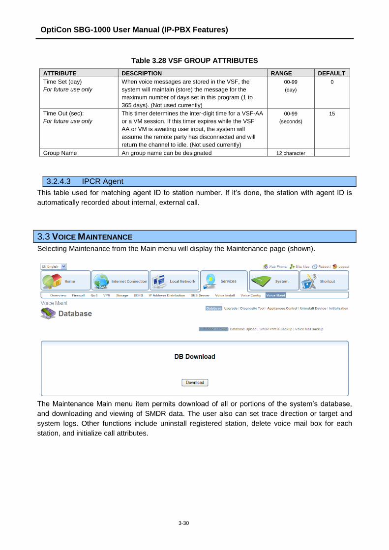
OptiCon SBG-1000 User Manual (IP-PBX Features)
3-30
Table 3.28 VSF GROUP ATTRIBUTES
ATTRIBUTE DESCRIPTION RANGE DEFAULT
Time Set (day)
For future use only
When voice messages are stored in the VSF, the
system will maintain (store) the message for the
maximum number of days set in this program (1 to
365 days). (Not used currently)
00-99
(day)
0
Time Out (sec):
For future use only
This timer determines the inter-digit time for a VSF-AA
or a VM session. If this timer expires while the VSF
AA or VM is awaiting user input, the system will
assume the remote party has disconnected and will
return the channel to idle. (Not used currently)
00-99
(seconds)
15
Group Name An group name can be designated 12 character
3.2.4.3 IPCR Agent
This table used for matching agent ID to station number. If it‟s done, the station with agent ID is
automatically recorded about internal, external call.
3.3 VOICE MAINTENANCE
Selecting Maintenance from the Main menu will display the Maintenance page (shown).
The Maintenance Main menu item permits download of all or portions of the system‟s database,
and downloading and viewing of SMDR data. The user also can set trace direction or target and
system logs. Other functions include uninstall registered station, delete voice mail box for each
station, and initialize call attributes.