ip router system - knxwarehouse.nl · ip router system product name: ip router ... an eib...
TRANSCRIPT
instabus KNX / EIB product documentation
Page: 1 of 21
For internal use only! hardware description
IP router
System
Product name: IP router (R2) Design: REG (rail-mounted device) Article-no.: J: IPR 100 REG ETS search path:
System devices / IP router / IP router
Issue: 05.03.2010 Functional description:
This product documentation describes the device with the release identifier "R2" on the device label. For older device variants (no release code) separate product documentation is available The IP router interconnects KNX / EIB lines via data networks using the Internet Protocol (IP). The IP router implements the EIBnet/IP standard so that it cannot only be used for routing KNX / EIB telegrams between lines via an IP network, but also for access to the bus from a PC or from other DP devices (visualization displays and applications). The IP router can thus also be used as an IP data interface for the ETS 3.0 after version "c". By using a LAN modem, an EIB installation can be remotely accessed even if there is no direct local data network connection between a PC and an IP router.
The use of the existing data network for communication between bus lines makes sense especially in non-residential buildings. The advantages are: - fast communication between KNX / EIB lines, - extending a KNX / EIB system by means of LAN and WAN beyond a building, - direct routing of KNX / EIB data to each network user (not in bus monitor mode) - KNX / EIB remote configuration from each network access point. In its capacity as an area/line coupler, the IP router interconnects two KNX / EIB lines to form a logical functional area ensuring at the same time the electrical separation between these lines. Each bus line of a KNX / EIB installation is thus electrically independent of other bus lines. The exact function of the device is determined by the physical address.
The device offers up to 4 KNXnet/IP tunneling connections, thus allowing, for example, simultaneous visualisation and configuration with ETS3. The connection to KNX is established via a bus connection terminal. The connection to the data network (IP via 10BaseT) is made via a RJ45 jack. The device requires an additional AC/DC 24 V power supply for operation. This power supply can be fed to the interface via the network cable as "Power over Ethernet” in accordance with IEEE 802.3af. Alternatively, the additional power supply can be drawn via the second terminal block (recommendation: white/yellow terminal) from an AC/DC 24 V safety extra-low voltage supply or from a bus voltage supply (unergulated voltage, DC 30 V). When the external power supply is connected to the second terminal block, the device automatically switches over to it.
instabus KNX / EIB product documentation
Page: 2 of 21
For internal use only! hardware description
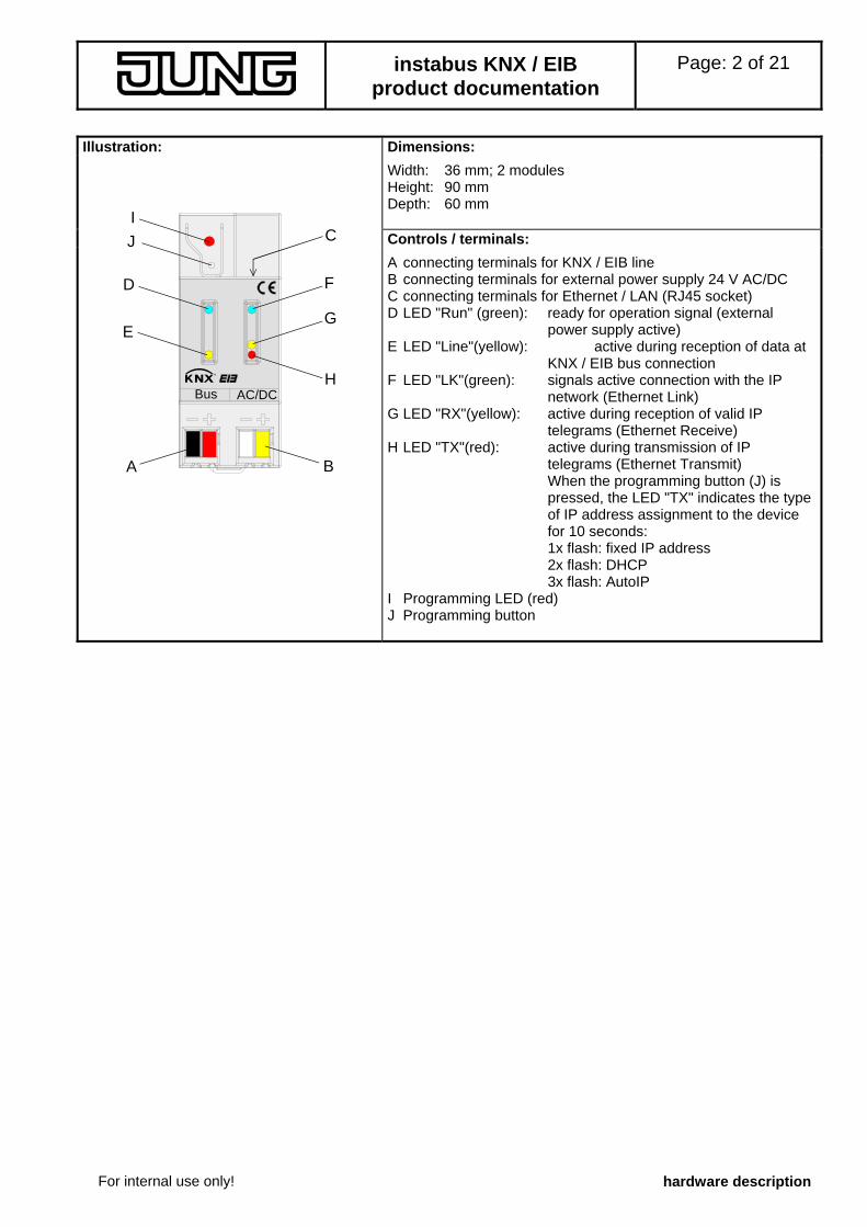
Illustration: Dimensions:
Width: 36 mm; 2 modules Height: 90 mm Depth: 60 mm
Controls / terminals:
A B
D
E
IJ
F
G
HBus AC/DC
C
A connecting terminals for KNX / EIB line B connecting terminals for external power supply 24 V AC/DC C connecting terminals for Ethernet / LAN (RJ45 socket) D LED "Run" (green): ready for operation signal (external
power supply active) E LED "Line"(yellow): active during reception of data at
KNX / EIB bus connection F LED "LK"(green): signals active connection with the IP
network (Ethernet Link) G LED "RX"(yellow): active during reception of valid IP
telegrams (Ethernet Receive) H LED "TX"(red): active during transmission of IP
telegrams (Ethernet Transmit) When the programming button (J) is pressed, the LED "TX" indicates the type of IP address assignment to the device for 10 seconds: 1x flash: fixed IP address 2x flash: DHCP 3x flash: AutoIP
I Programming LED (red) J Programming button
instabus KNX / EIB product documentation
Page: 3 of 21
For internal use only! hardware description
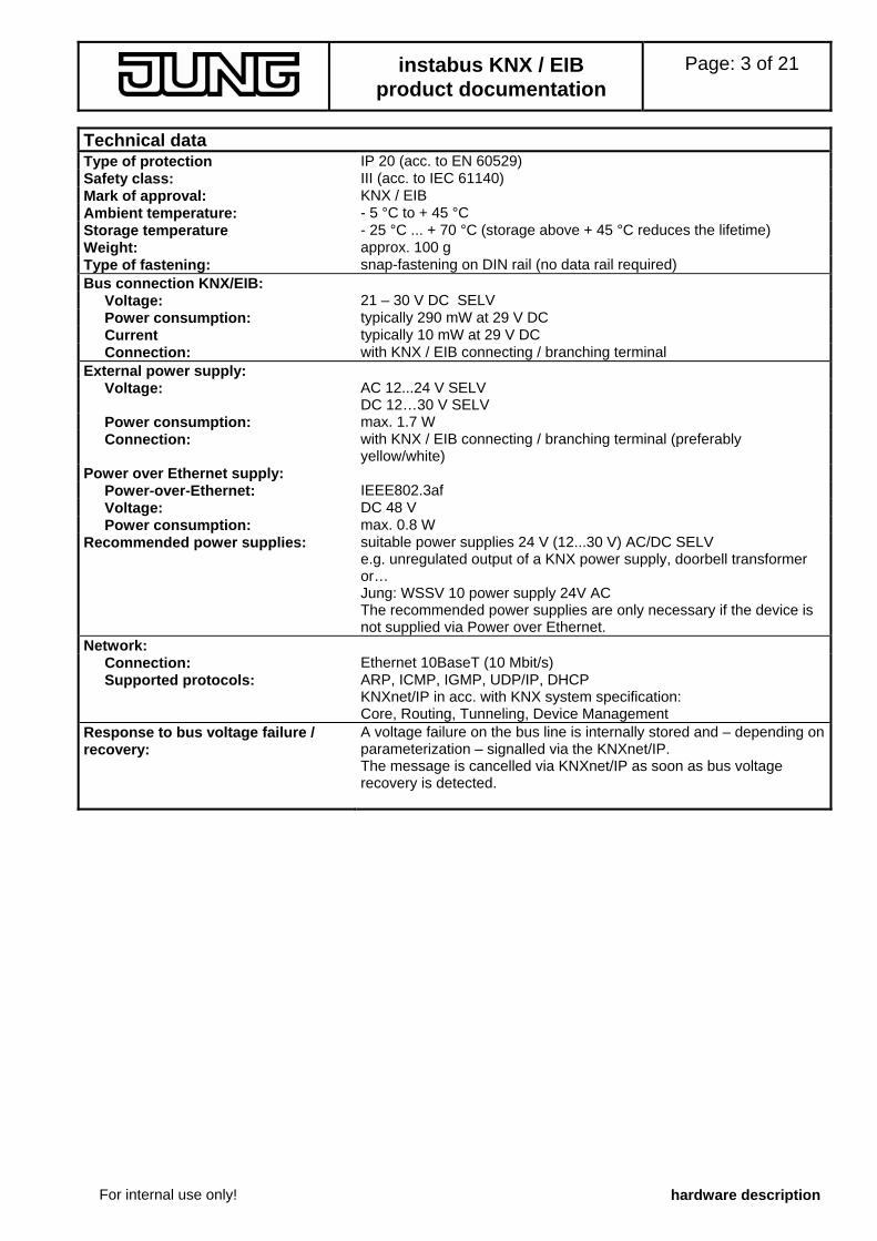
Technical data Type of protection IP 20 (acc. to EN 60529) Safety class: III (acc. to IEC 61140) Mark of approval: KNX / EIB Ambient temperature: - 5 °C to + 45 °C Storage temperature - 25 °C ... + 70 °C (storage above + 45 °C reduces the lifetime) Weight: approx. 100 g Type of fastening: snap-fastening on DIN rail (no data rail required) Bus connection KNX/EIB:
Voltage: 21 – 30 V DC SELV Power consumption: typically 290 mW at 29 V DC Current typically 10 mW at 29 V DC Connection: with KNX / EIB connecting / branching terminal
External power supply: Voltage: AC 12...24 V SELV
DC 12…30 V SELV Power consumption: max. 1.7 W Connection: with KNX / EIB connecting / branching terminal (preferably
yellow/white) Power over Ethernet supply:
Power-over-Ethernet: IEEE802.3af Voltage: DC 48 V Power consumption: max. 0.8 W
Recommended power supplies: suitable power supplies 24 V (12...30 V) AC/DC SELV e.g. unregulated output of a KNX power supply, doorbell transformer or… Jung: WSSV 10 power supply 24V AC The recommended power supplies are only necessary if the device is not supplied via Power over Ethernet.
Network: Connection: Ethernet 10BaseT (10 Mbit/s) Supported protocols: ARP, ICMP, IGMP, UDP/IP, DHCP
KNXnet/IP in acc. with KNX system specification: Core, Routing, Tunneling, Device Management
Response to bus voltage failure / recovery:
A voltage failure on the bus line is internally stored and – depending on parameterization – signalled via the KNXnet/IP. The message is cancelled via KNXnet/IP as soon as bus voltage recovery is detected.
instabus KNX / EIB product documentation
Page: 4 of 21
For internal use only! hardware description
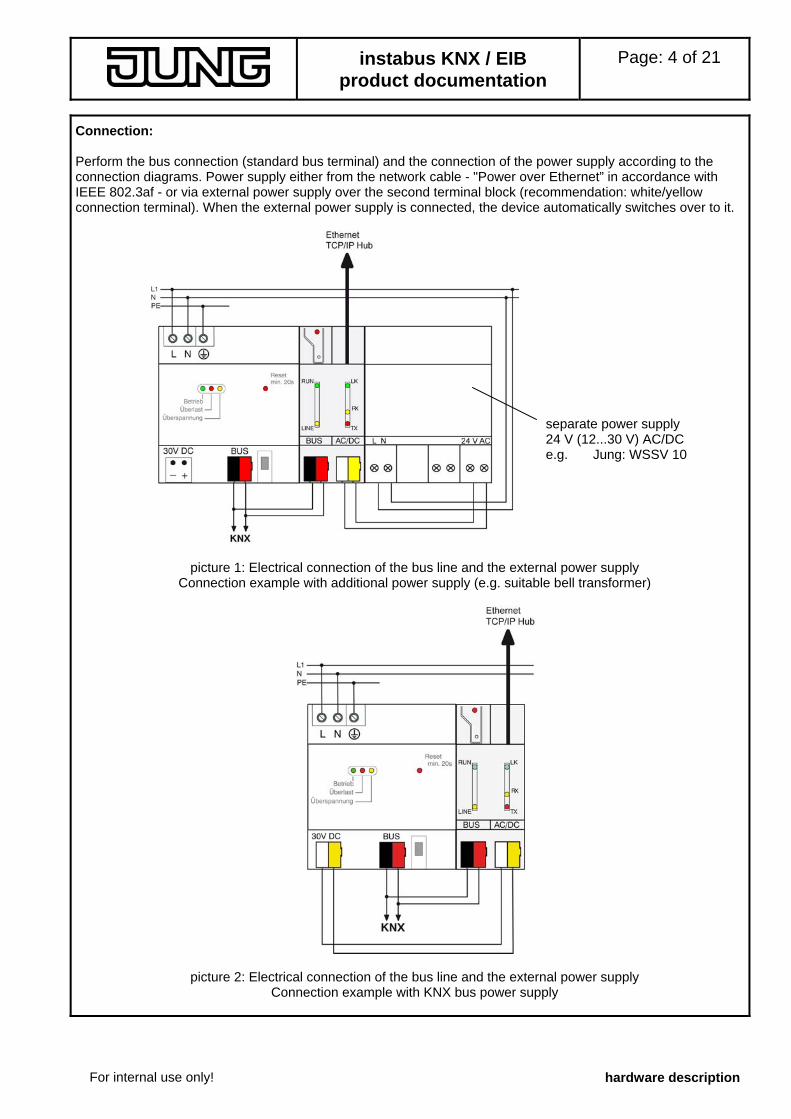
Connection: Perform the bus connection (standard bus terminal) and the connection of the power supply according to the connection diagrams. Power supply either from the network cable - "Power over Ethernet” in accordance with IEEE 802.3af - or via external power supply over the second terminal block (recommendation: white/yellow connection terminal). When the external power supply is connected, the device automatically switches over to it.
picture 1: Electrical connection of the bus line and the external power supply Connection example with additional power supply (e.g. suitable bell transformer)
picture 2: Electrical connection of the bus line and the external power supply Connection example with KNX bus power supply
separate power supply 24 V (12...30 V) AC/DC e.g. Jung: WSSV 10

instabus KNX / EIB product documentation
Page: 5 of 21
For internal use only! hardware description
Hardware information
• The filter tables are stored in a non-volatile memory (flash). This means that the stored addresses are not lost after a system voltage failure. And internal backup battery is not needed.
• Depending on application, access requirements, data security and data volume it may be advisable to install independent network paths for individual services using the IP network.
instabus KNX / EIB product documentation
Page: 6 of 21
For internal use only! hardware description
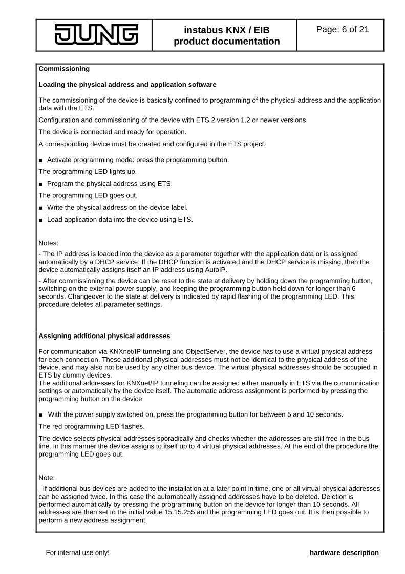
Commissioning Loading the physical address and application software The commissioning of the device is basically confined to programming of the physical address and the application data with the ETS.
Configuration and commissioning of the device with ETS 2 version 1.2 or newer versions.
The device is connected and ready for operation.
A corresponding device must be created and configured in the ETS project. ■ Activate programming mode: press the programming button.
The programming LED lights up.
■ Program the physical address using ETS.
The programming LED goes out.
■ Write the physical address on the device label.
■ Load application data into the device using ETS. Notes:
- The IP address is loaded into the device as a parameter together with the application data or is assigned automatically by a DHCP service. If the DHCP function is activated and the DHCP service is missing, then the device automatically assigns itself an IP address using AutoIP.
- After commissioning the device can be reset to the state at delivery by holding down the programming button, switching on the external power supply, and keeping the programming button held down for longer than 6 seconds. Changeover to the state at delivery is indicated by rapid flashing of the programming LED. This procedure deletes all parameter settings. Assigning additional physical addresses For communication via KNXnet/IP tunneling and ObjectServer, the device has to use a virtual physical address for each connection. These additional physical addresses must not be identical to the physical address of the device, and may also not be used by any other bus device. The virtual physical addresses should be occupied in ETS by dummy devices. The additional addresses for KNXnet/IP tunneling can be assigned either manually in ETS via the communication settings or automatically by the device itself. The automatic address assignment is performed by pressing the programming button on the device. ■ With the power supply switched on, press the programming button for between 5 and 10 seconds.
The red programming LED flashes.
The device selects physical addresses sporadically and checks whether the addresses are still free in the bus line. In this manner the device assigns to itself up to 4 virtual physical addresses. At the end of the procedure the programming LED goes out. Note:
- If additional bus devices are added to the installation at a later point in time, one or all virtual physical addresses can be assigned twice. In this case the automatically assigned addresses have to be deleted. Deletion is performed automatically by pressing the programming button on the device for longer than 10 seconds. All addresses are then set to the initial value 15.15.255 and the programming LED goes out. It is then possible to perform a new address assignment.
instabus KNX / EIB product documentation
Page: 7 of 21
software description
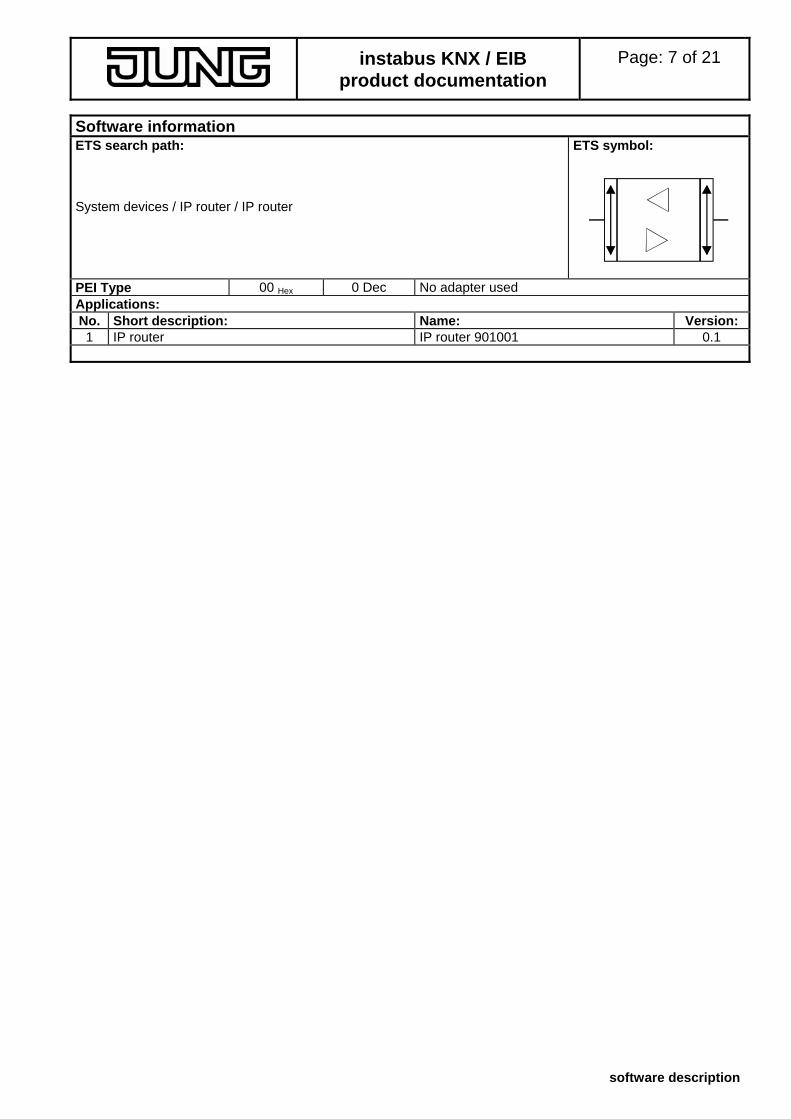
Software information ETS search path: ETS symbol:
System devices / IP router / IP router
00 Hex 0 Dec No adapter used PEI Type
Applications: No. Short description: Name: Version: 1 IP router IP router 901001 0.1
instabus KNX / EIB product documentation
Page: 8 of 21
software description
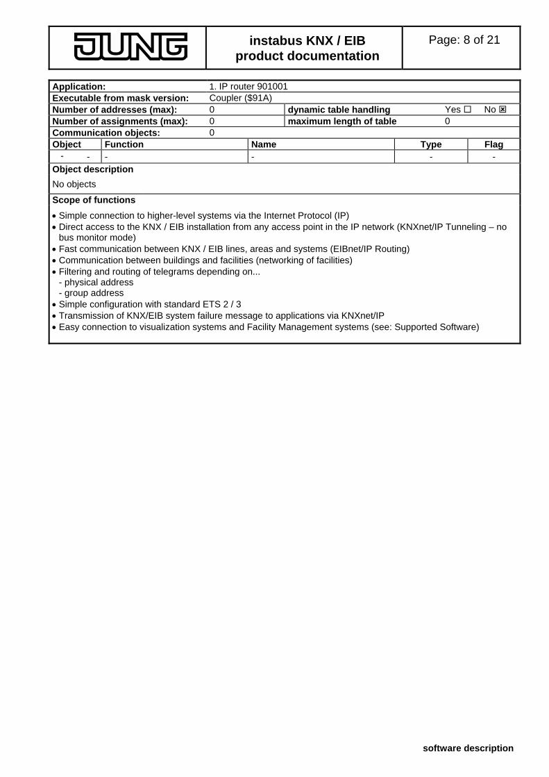
Application: 1. IP router 901001 Executable from mask version: Coupler ($91A) Number of addresses (max): 0 dynamic table handling Yes No Number of assignments (max): 0 maximum length of table 0 Communication objects: 0 Object Function Name Type Flag
- - - - - - Object description
No objects
Scope of functions
• Simple connection to higher-level systems via the Internet Protocol (IP) • Direct access to the KNX / EIB installation from any access point in the IP network (KNXnet/IP Tunneling – no
bus monitor mode) • Fast communication between KNX / EIB lines, areas and systems (EIBnet/IP Routing) • Communication between buildings and facilities (networking of facilities) • Filtering and routing of telegrams depending on...
- physical address - group address
• Simple configuration with standard ETS 2 / 3 • Transmission of KNX/EIB system failure message to applications via KNXnet/IP • Easy connection to visualization systems and Facility Management systems (see: Supported Software)
instabus KNX / EIB product documentation
Page: 9 of 21
software description
Functional description
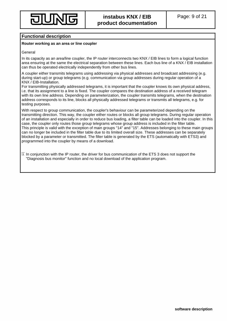
Router working as an area or line coupler General
In its capacity as an area/line coupler, the IP router interconnects two KNX / EIB lines to form a logical function area ensuring at the same the electrical separation between these lines. Each bus line of a KNX / EIB installation can thus be operated electrically independently from other bus lines.
A coupler either transmits telegrams using addressing via physical addresses and broadcast addressing (e.g. during start-up) or group telegrams (e.g. communication via group addresses during regular operation of a KNX / EIB-Installation. For transmitting physically addressed telegrams, it is important that the coupler knows its own physical address, i.e. that its assignment to a line is fixed. The coupler compares the destination address of a received telegram with its own line address. Depending on parameterization, the coupler transmits telegrams, when the destination address corresponds to its line, blocks all physically addressed telegrams or transmits all telegrams, e.g. for testing purposes.
With respect to group communication, the coupler's behaviour can be parameterized depending on the transmitting direction. This way, the coupler either routes or blocks all group telegrams. During regular operation of an installation and especially in order to reduce bus loading, a filter table can be loaded into the coupler. In this case, the coupler only routes those group telegrams whose group address is included in the filter table. This principle is valid with the exception of main groups "14" and "15". Addresses belonging to these main groups can no longer be included in the filter table due to its limited overall size. These addresses can be separately blocked by a parameter or transmitted. The filter table is generated by the ETS (automatically with ETS3) and programmed into the coupler by means of a download.
In conjunction with the IP router, the driver for bus communication of the ETS 3 does not support the "Diagnosis bus monitor" function and no local download of the application program.
instabus KNX / EIB product documentation
Page: 10 of 21
software description
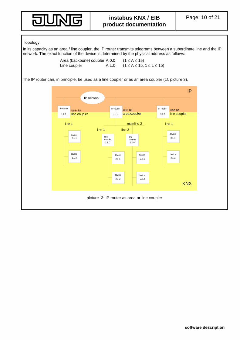
Topology
In its capacity as an area / line coupler, the IP router transmits telegrams between a subordinate line and the IP network. The exact function of the device is determined by the physical address as follows:
Area (backbone) coupler A.0.0 (1 ≤ A ≤ 15) Line coupler A.L.0 (1 ≤ A ≤ 15, 1 ≤ L ≤ 15)
The IP router can, in principle, be used as a line coupler or as an area coupler (cf. picture 3).
line-coupler
2.1.0 line-coupler
2.2.0
device 1.1.1
1.1.2
2.1.1
2.1.2
2.2.1
2.2.2
mainline 2
IP network
IP router
1.1.0
2.0.0
3.1.1
3.1.2
3.1.0
IP router IP router
device device
device
device
device
device
device
KNX
IP
line 1 line 1
line 1 line 2
use asline coupler
use asarea coupler
use asline coupler
picture 3: IP router as area or line coupler
instabus KNX / EIB product documentation
Page: 11 of 21
software description
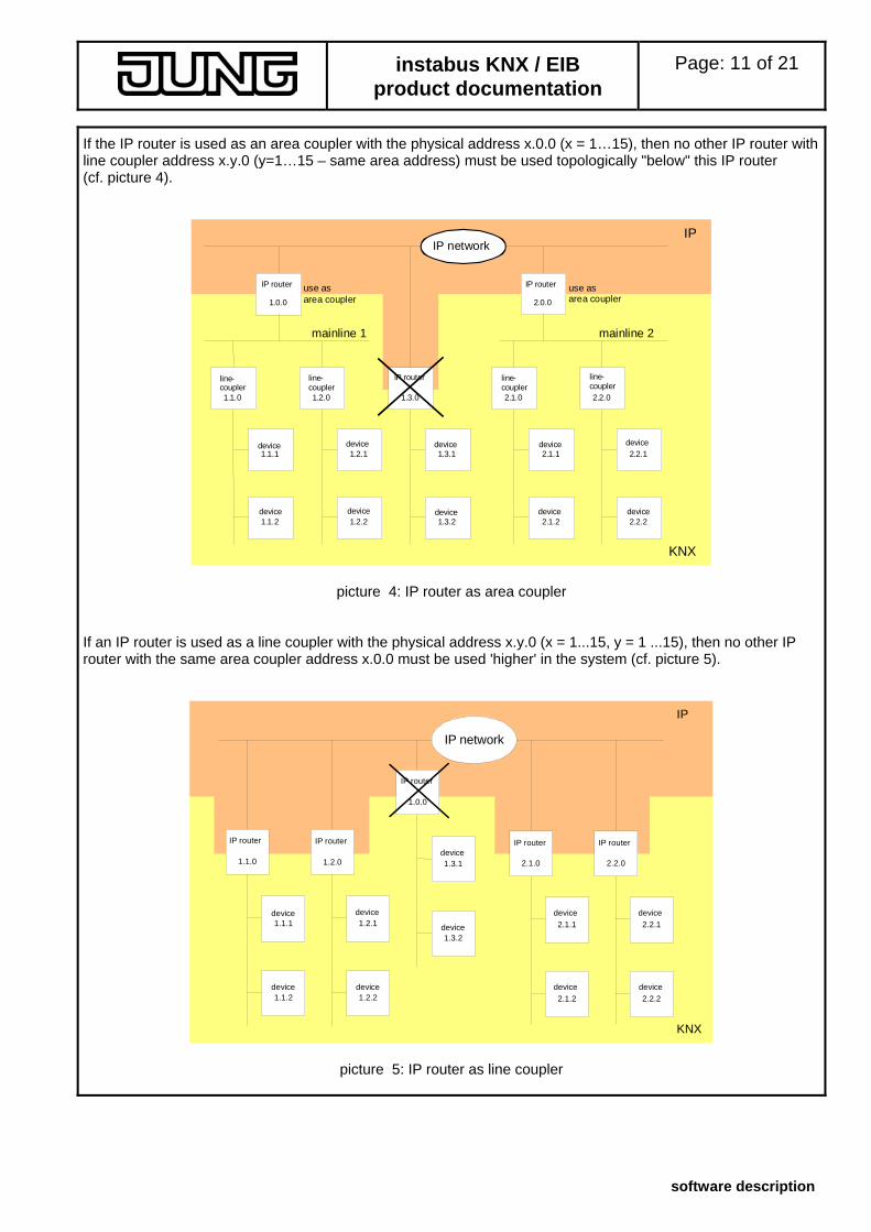
If the IP router is used as an area coupler with the physical address x.0.0 (x = 1…15), then no other IP router with line coupler address x.y.0 (y=1…15 – same area address) must be used topologically "below" this IP router (cf. picture 4).
KNX
IP
2.0.0
mainline 1 mainline 2
line-coupler
1.1.0
1.2.0
2.1.0
2.2.0
device 1.1.1
1.1.2
1.2.1
1.2.2
1.3.1
1.3.2
2.1.1
2.1.2
2.2.1
use asarea coupler
2.2.2
IP network
IP router
line-coupler
line-coupler
line-coupler
device
use asarea coupler
IP router
1.0.0
1.3.0
IP router
device
device device
device
device
device
device
device
picture 4: IP router as area coupler If an IP router is used as a line coupler with the physical address x.y.0 (x = 1...15, y = 1 ...15), then no other IP router with the same area coupler address x.0.0 must be used 'higher' in the system (cf. picture 5).
IP
device 1.1.1
1.1.2
1.2.1
1.2.2
1.3.1
1.3.2
IP network
device
1.0.0 IP router
1.2.0
IP router
IP Router
1.1.0
1.1.0
IP router
KNX
2.1.1
2.1.2
2.2.1
2.2.2
2.2.0
2.1.0
IP router IP router
device
device
device
device
device device
device device
picture 5: IP router as line coupler
instabus KNX / EIB product documentation
Page: 12 of 21
software description
Note:
The perfect functioning of the IP router as an area or a line coupler (KNXnet/IP Routing) depends on network components supporting IP multicasting. Network / LAN routers in particular must permit a setting or be set in such a way that IP multicasting datagrams will be forwarded. For KNXnet/IP Routing, the IP multicast address reserved for this purpose is address 224.0.23.12. Function as IP data interface A direct connection between a networked PC or other DP terminal devices (e.g. visualization displays and applications) in the network and the KNX / EIB can be established via an IP data network and the IP router. In that case, the bus can be accessed from any point in the IP data network.
The ETS3 (from version 3.0c onwards) permits configuring KNX/EIB installations via the existing IP data network and uses the IP router like any other conventional serial RS232 or USB data interface for communication with the bus. This includes also downloading of bus devices or the function of the group bus monitor (no support of bus monitor mode). For communication via KNXnet/IP tunnelling and ObjectServer, the device must use a virtual physical address for each connection.. These additional physical addresses must not be identical to the physical address of the device, and may also not be used by any other bus device. The virtual physical addresses should be occupied in ETS by dummy devices. The additional addresses for KNXnet/IP tunneling can be assigned either manually in ETS via the communication settings or automatically by the device itself. To configure the communication interface in ETS 3, perform the following steps... To configure the communication interface, the following steps are required:
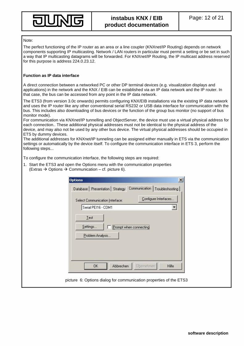
1. Start the ETS3 and open the Options menu with the communication properties (Extras Options Communication – cf. picture 6).
picture 6: Options dialog for communication properties of the ETS3
instabus KNX / EIB product documentation
Page: 13 of 21
software description
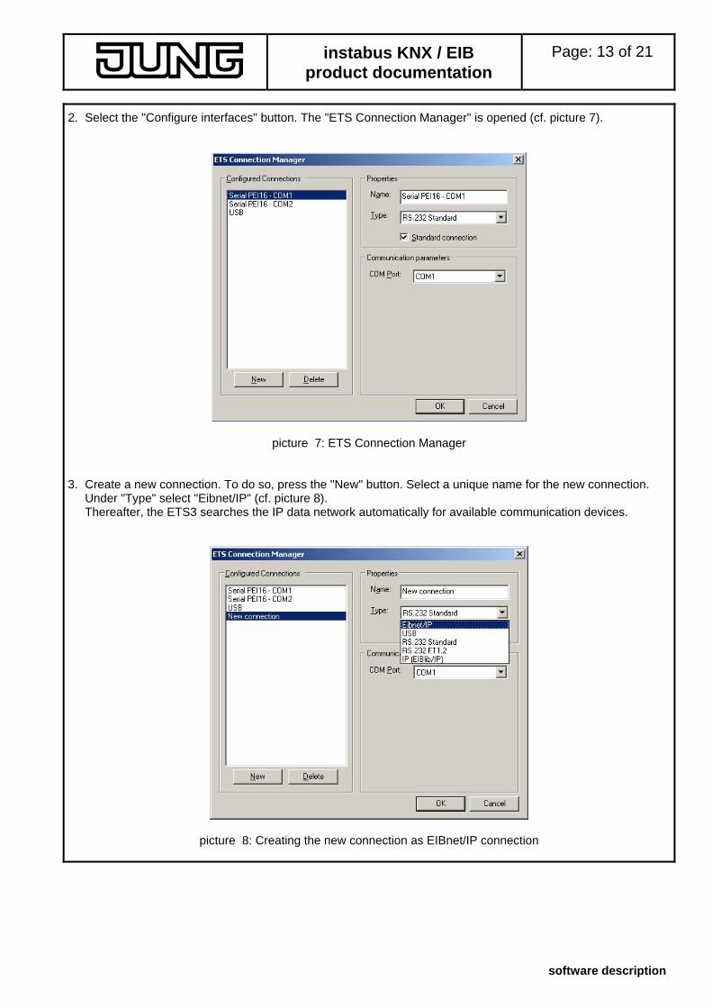
2. Select the "Configure interfaces" button. The "ETS Connection Manager" is opened (cf. picture 7).
picture 7: ETS Connection Manager 3. Create a new connection. To do so, press the "New" button. Select a unique name for the new connection.
Under "Type" select "Eibnet/IP" (cf. picture 8). Thereafter, the ETS3 searches the IP data network automatically for available communication devices.
picture 8: Creating the new connection as EIBnet/IP connection
instabus KNX / EIB product documentation
Page: 14 of 21
software description
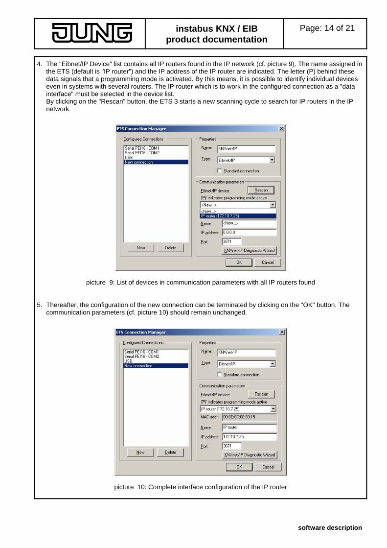
4. The "Eibnet/IP Device" list contains all IP routers found in the IP network (cf. picture 9). The name assigned in the ETS (default is "IP router") and the IP address of the IP router are indicated. The letter (P) behind these data signals that a programming mode is activated. By this means, it is possible to identify individual devices even in systems with several routers. The IP router which is to work in the configured connection as a "data interface" must be selected in the device list. By clicking on the "Rescan" button, the ETS 3 starts a new scanning cycle to search for IP routers in the IP network.
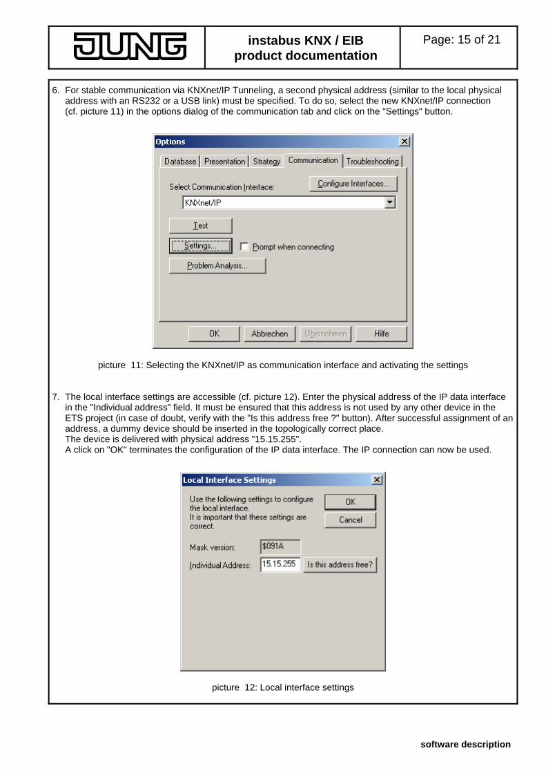
picture 9: List of devices in communication parameters with all IP routers found 5. Thereafter, the configuration of the new connection can be terminated by clicking on the "OK" button. The
communication parameters (cf. picture 10) should remain unchanged.
picture 10: Complete interface configuration of the IP router
instabus KNX / EIB product documentation
Page: 15 of 21
software description
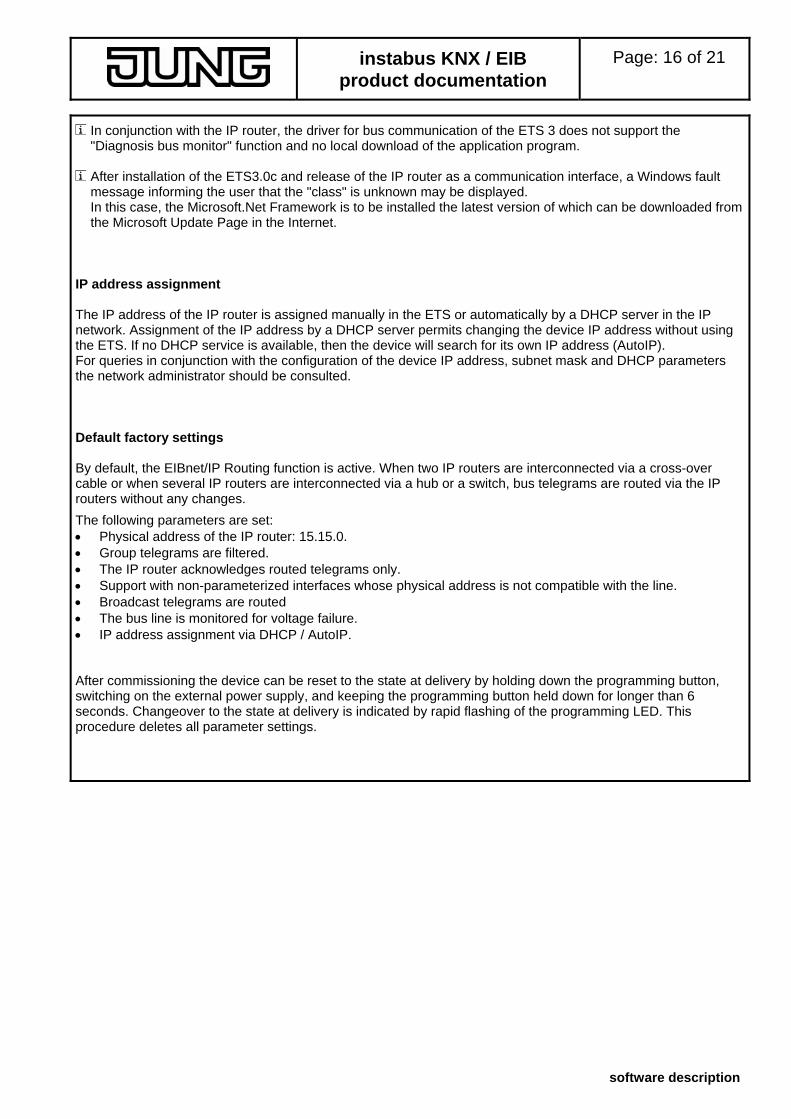
6. For stable communication via KNXnet/IP Tunneling, a second physical address (similar to the local physical address with an RS232 or a USB link) must be specified. To do so, select the new KNXnet/IP connection (cf. picture 11) in the options dialog of the communication tab and click on the "Settings" button.
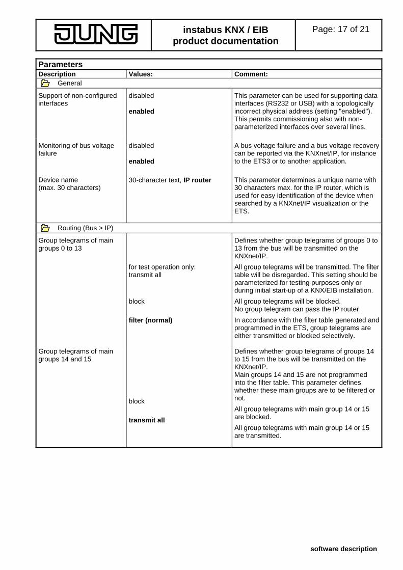
picture 11: Selecting the KNXnet/IP as communication interface and activating the settings 7. The local interface settings are accessible (cf. picture 12). Enter the physical address of the IP data interface
in the "Individual address" field. It must be ensured that this address is not used by any other device in the ETS project (in case of doubt, verify with the "Is this address free ?" button). After successful assignment of an address, a dummy device should be inserted in the topologically correct place. The device is delivered with physical address "15.15.255". A click on "OK" terminates the configuration of the IP data interface. The IP connection can now be used.
picture 12: Local interface settings
instabus KNX / EIB product documentation
Page: 16 of 21
software description
In conjunction with the IP router, the driver for bus communication of the ETS 3 does not support the "Diagnosis bus monitor" function and no local download of the application program.
After installation of the ETS3.0c and release of the IP router as a communication interface, a Windows fault message informing the user that the "class" is unknown may be displayed. In this case, the Microsoft.Net Framework is to be installed the latest version of which can be downloaded from the Microsoft Update Page in the Internet.
IP address assignment The IP address of the IP router is assigned manually in the ETS or automatically by a DHCP server in the IP network. Assignment of the IP address by a DHCP server permits changing the device IP address without using the ETS. If no DHCP service is available, then the device will search for its own IP address (AutoIP). For queries in conjunction with the configuration of the device IP address, subnet mask and DHCP parameters the network administrator should be consulted. Default factory settings By default, the EIBnet/IP Routing function is active. When two IP routers are interconnected via a cross-over cable or when several IP routers are interconnected via a hub or a switch, bus telegrams are routed via the IP routers without any changes.
The following parameters are set: • Physical address of the IP router: 15.15.0. • Group telegrams are filtered. • The IP router acknowledges routed telegrams only. • Support with non-parameterized interfaces whose physical address is not compatible with the line. • Broadcast telegrams are routed • The bus line is monitored for voltage failure. • IP address assignment via DHCP / AutoIP. After commissioning the device can be reset to the state at delivery by holding down the programming button, switching on the external power supply, and keeping the programming button held down for longer than 6 seconds. Changeover to the state at delivery is indicated by rapid flashing of the programming LED. This procedure deletes all parameter settings.
instabus KNX / EIB product documentation
Page: 17 of 21
software description
Parameters Description Values: Comment:
General
Support of non-configured interfaces
disabled This parameter can be used for supporting data interfaces (RS232 or USB) with a topologically incorrect physical address (setting "enabled"). This permits commissioning also with non-parameterized interfaces over several lines.
enabled
Monitoring of bus voltage failure
disabled A bus voltage failure and a bus voltage recovery can be reported via the KNXnet/IP, for instance to the ETS3 or to another application.
enabled
Device name (max. 30 characters)
This parameter determines a unique name with 30 characters max. for the IP router, which is used for easy identification of the device when searched by a KNXnet/IP visualization or the ETS.
30-character text, IP router
Routing (Bus > IP)
Group telegrams of main groups 0 to 13
Defines whether group telegrams of groups 0 to 13 from the bus will be transmitted on the KNXnet/IP.
for test operation only: transmit all
All group telegrams will be transmitted. The filter table will be disregarded. This setting should be parameterized for testing purposes only or during initial start-up of a KNX/EIB installation.
block All group telegrams will be blocked. No group telegram can pass the IP router.
In accordance with the filter table generated and programmed in the ETS, group telegrams are either transmitted or blocked selectively.
filter (normal)
Group telegrams of main groups 14 and 15
Defines whether group telegrams of groups 14 to 15 from the bus will be transmitted on the KNXnet/IP.
Main groups 14 and 15 are not programmed
into the filter table. This parameter defines whether these main groups are to be filtered or not.
block
All group telegrams with main group 14 or 15 are blocked.
transmit all
All group telegrams with main group 14 or 15 are transmitted.
instabus KNX / EIB product documentation
Page: 18 of 21
software description
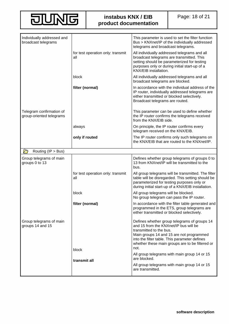
Individually addressed and broadcast telegrams
This parameter is used to set the filter function Bus > KNXnet/IP of the individually addressed telegrams and broadcast telegrams.
for test operation only: transmit all
All individually addressed telegrams and all broadcast telegrams are transmitted. This setting should be parameterized for testing purposes only or during initial start-up of a KNX/EIB installation.
block All individually addressed telegrams and all broadcast telegrams are blocked.
In accordance with the individual address of the IP router, individually addressed telegrams are either transmitted or blocked selectively. Broadcast telegrams are routed.
filter (normal)
Telegram confirmation of group-oriented telegrams
This parameter can be used to define whether the IP router confirms the telegrams received from the KNX/EIB side.
always On principle, the IP router confirms every telegram received on the KNX/EIB.
The IP router confirms only such telegrams on the KNX/EIB that are routed to the KNXnet/IP.
only if routed
Routing (IP > Bus)
Group telegrams of main groups 0 to 13
Defines whether group telegrams of groups 0 to 13 from KNXnet/IP will be transmitted to the bus.
for test operation only: transmit all
All group telegrams will be transmitted. The filter table will be disregarded. This setting should be parameterized for testing purposes only or during initial start-up of a KNX/EIB installation.
block All group telegrams will be blocked. No group telegram can pass the IP router.
In accordance with the filter table generated and programmed in the ETS, group telegrams are either transmitted or blocked selectively.
filter (normal)
Group telegrams of main groups 14 and 15
Defines whether group telegrams of groups 14 and 15 from the KNXnet/IP bus will be transmitted to the bus.
Main groups 14 and 15 are not programmed
into the filter table. This parameter defines whether these main groups are to be filtered or not.
block
All group telegrams with main group 14 or 15 are blocked.
transmit all
All group telegrams with main group 14 or 15 are transmitted.
instabus KNX / EIB product documentation
Page: 19 of 21
software description
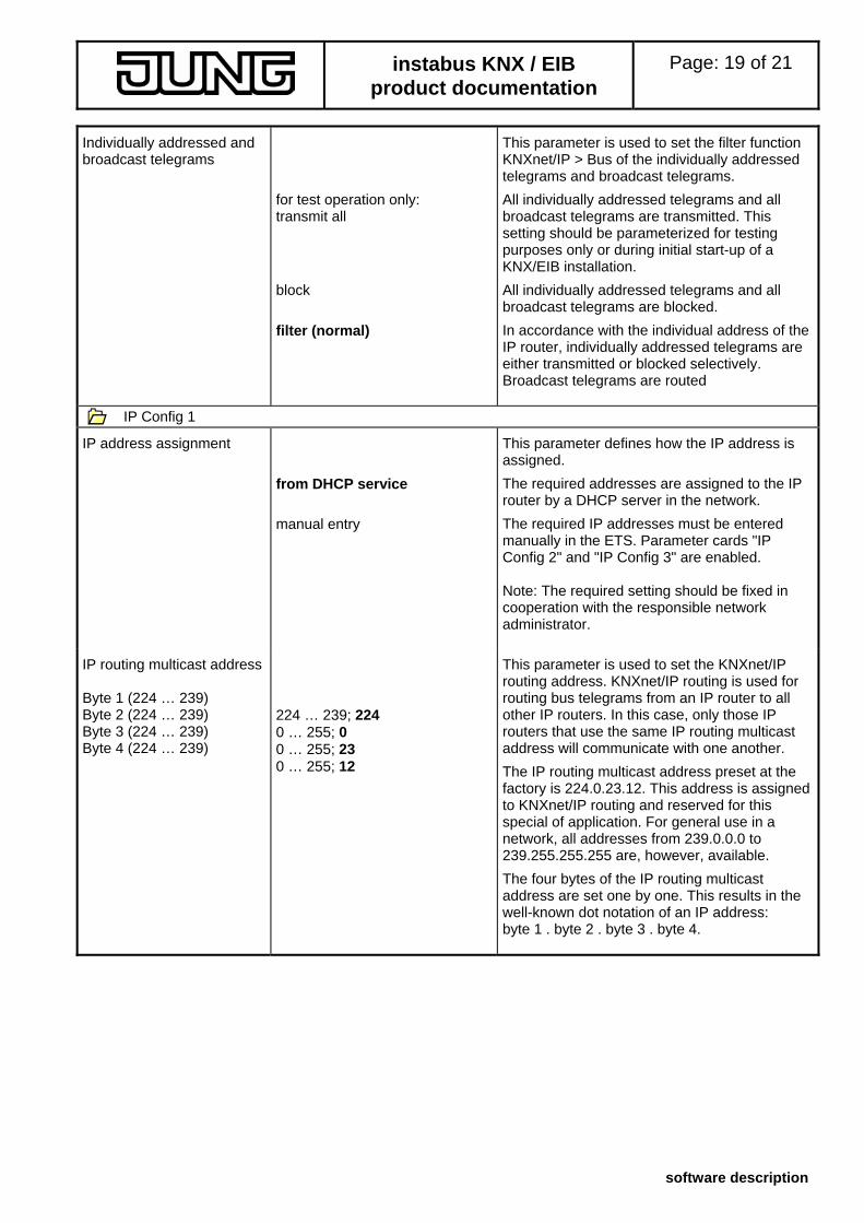
Individually addressed and broadcast telegrams
This parameter is used to set the filter function KNXnet/IP > Bus of the individually addressed telegrams and broadcast telegrams.
for test operation only: transmit all
All individually addressed telegrams and all broadcast telegrams are transmitted. This setting should be parameterized for testing purposes only or during initial start-up of a KNX/EIB installation.
block All individually addressed telegrams and all broadcast telegrams are blocked.
In accordance with the individual address of the IP router, individually addressed telegrams are either transmitted or blocked selectively. Broadcast telegrams are routed
filter (normal)
IP Config 1
IP address assignment This parameter defines how the IP address is assigned.
The required addresses are assigned to the IP router by a DHCP server in the network.
from DHCP service
The required IP addresses must be entered manually in the ETS. Parameter cards "IP Config 2" and "IP Config 3" are enabled.
manual entry
Note: The required setting should be fixed in cooperation with the responsible network administrator.
IP routing multicast address This parameter is used to set the KNXnet/IP routing address. KNXnet/IP routing is used for routing bus telegrams from an IP router to all other IP routers. In this case, only those IP routers that use the same IP routing multicast address will communicate with one another.
Byte 1 (224 … 239) Byte 2 (224 … 239) 224 … 239; 224 Byte 3 (224 … 239) 0 … 255; 0 Byte 4 (224 … 239) 0 … 255; 23
0 … 255; 12 The IP routing multicast address preset at the factory is 224.0.23.12. This address is assigned to KNXnet/IP routing and reserved for this special of application. For general use in a network, all addresses from 239.0.0.0 to 239.255.255.255 are, however, available.
The four bytes of the IP routing multicast address are set one by one. This results in the well-known dot notation of an IP address: byte 1 . byte 2 . byte 3 . byte 4.
instabus KNX / EIB product documentation
Page: 20 of 21
software description
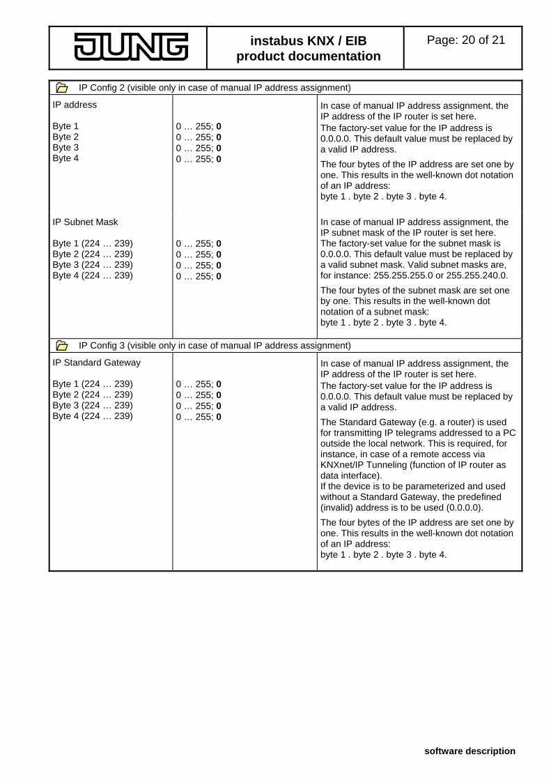
IP Config 2 (visible only in case of manual IP address assignment)
IP address In case of manual IP address assignment, the IP address of the IP router is set here.
Byte 1 0 … 255; 0 The factory-set value for the IP address is 0.0.0.0. This default value must be replaced by a valid IP address.
Byte 2 0 … 255; 0 Byte 3 0 … 255; 0 Byte 4 0 … 255; 0
The four bytes of the IP address are set one by one. This results in the well-known dot notation of an IP address: byte 1 . byte 2 . byte 3 . byte 4.
IP Subnet Mask In case of manual IP address assignment, the IP subnet mask of the IP router is set here.
Byte 1 (224 … 239) The factory-set value for the subnet mask is 0.0.0.0. This default value must be replaced by a valid subnet mask. Valid subnet masks are, for instance: 255.255.255.0 or 255.255.240.0.
0 … 255; 0 Byte 2 (224 … 239) 0 … 255; 0 Byte 3 (224 … 239) 0 … 255; 0 Byte 4 (224 … 239) 0 … 255; 0
The four bytes of the subnet mask are set one by one. This results in the well-known dot notation of a subnet mask: byte 1 . byte 2 . byte 3 . byte 4.
IP Config 3 (visible only in case of manual IP address assignment)
IP Standard Gateway In case of manual IP address assignment, the IP address of the IP router is set here.
Byte 1 (224 … 239) 0 … 255; 0 The factory-set value for the IP address is 0.0.0.0. This default value must be replaced by a valid IP address.
Byte 2 (224 … 239) 0 … 255; 0 Byte 3 (224 … 239) 0 … 255; 0 Byte 4 (224 … 239) 0 … 255; 0
The Standard Gateway (e.g. a router) is used for transmitting IP telegrams addressed to a PC outside the local network. This is required, for instance, in case of a remote access via KNXnet/IP Tunneling (function of IP router as data interface).
If the device is to be parameterized and used without a Standard Gateway, the predefined (invalid) address is to be used (0.0.0.0).
The four bytes of the IP address are set one by one. This results in the well-known dot notation of an IP address: byte 1 . byte 2 . byte 3 . byte 4.
instabus KNX / EIB product documentation
Page: 21 of 21
software description
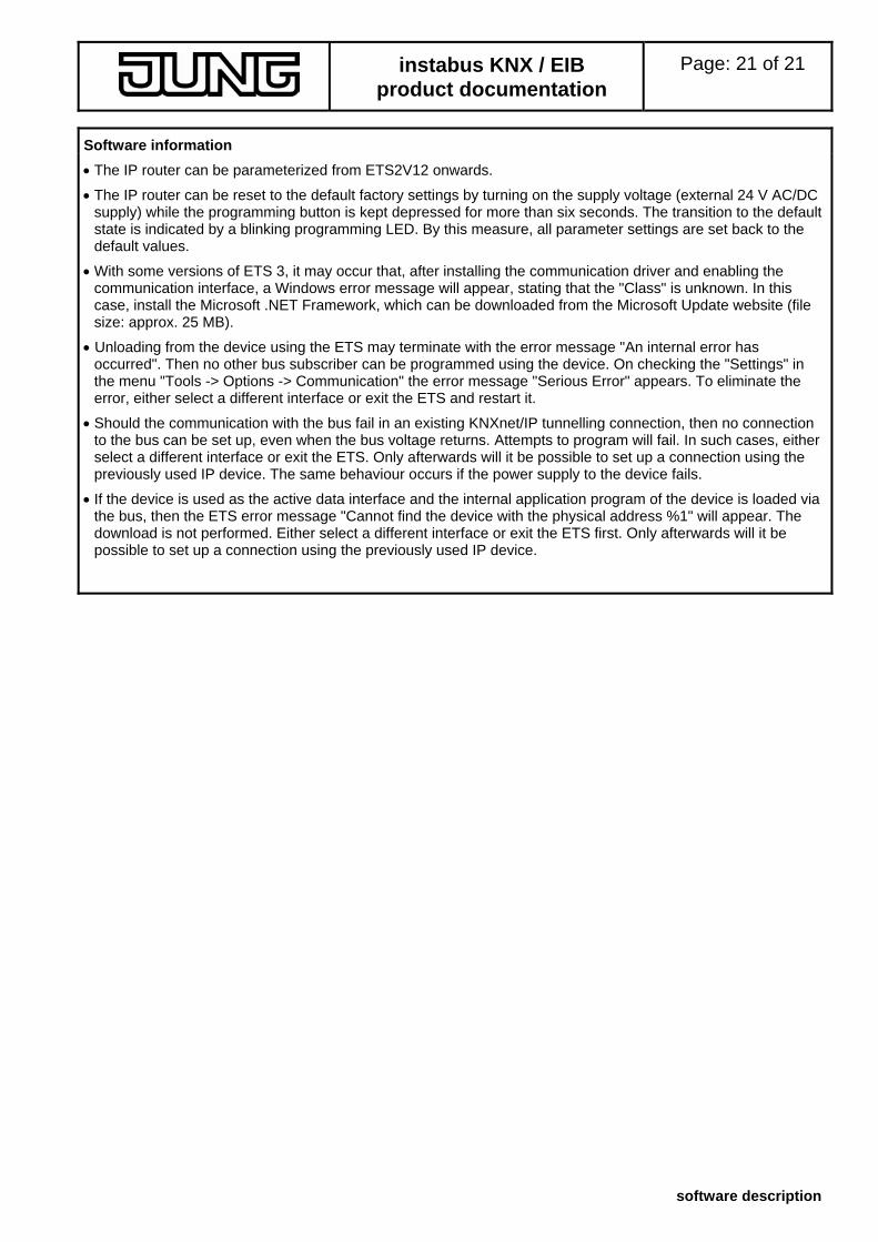
Software information
• The IP router can be parameterized from ETS2V12 onwards.
• The IP router can be reset to the default factory settings by turning on the supply voltage (external 24 V AC/DC supply) while the programming button is kept depressed for more than six seconds. The transition to the default state is indicated by a blinking programming LED. By this measure, all parameter settings are set back to the default values.
• With some versions of ETS 3, it may occur that, after installing the communication driver and enabling the communication interface, a Windows error message will appear, stating that the "Class" is unknown. In this case, install the Microsoft .NET Framework, which can be downloaded from the Microsoft Update website (file size: approx. 25 MB).
• Unloading from the device using the ETS may terminate with the error message "An internal error has occurred". Then no other bus subscriber can be programmed using the device. On checking the "Settings" in the menu "Tools -> Options -> Communication" the error message "Serious Error" appears. To eliminate the error, either select a different interface or exit the ETS and restart it.
• Should the communication with the bus fail in an existing KNXnet/IP tunnelling connection, then no connection to the bus can be set up, even when the bus voltage returns. Attempts to program will fail. In such cases, either select a different interface or exit the ETS. Only afterwards will it be possible to set up a connection using the previously used IP device. The same behaviour occurs if the power supply to the device fails.
• If the device is used as the active data interface and the internal application program of the device is loaded via the bus, then the ETS error message "Cannot find the device with the physical address %1" will appear. The download is not performed. Either select a different interface or exit the ETS first. Only afterwards will it be possible to set up a connection using the previously used IP device.