ip routing: bgp configuration guide, cisco ios release 12
TRANSCRIPT

IP Routing: BGP Configuration Guide,Cisco IOS Release 12.4T
Americas HeadquartersCisco Systems, Inc.170 West Tasman DriveSan Jose, CA 95134-1706USAhttp://www.cisco.comTel: 408 526-4000 800 553-NETS (6387)Fax: 408 527-0883

THE SPECIFICATIONS AND INFORMATION REGARDING THE PRODUCTS IN THIS MANUAL ARE SUBJECT TO CHANGE WITHOUT NOTICE. ALL STATEMENTS,INFORMATION, AND RECOMMENDATIONS IN THIS MANUAL ARE BELIEVED TO BE ACCURATE BUT ARE PRESENTED WITHOUT WARRANTY OF ANY KIND,EXPRESS OR IMPLIED. USERS MUST TAKE FULL RESPONSIBILITY FOR THEIR APPLICATION OF ANY PRODUCTS.
THE SOFTWARE LICENSE AND LIMITED WARRANTY FOR THE ACCOMPANYING PRODUCT ARE SET FORTH IN THE INFORMATION PACKET THAT SHIPPEDWITH THE PRODUCT AND ARE INCORPORATED HEREIN BY THIS REFERENCE. IF YOU ARE UNABLE TO LOCATE THE SOFTWARE LICENSE OR LIMITEDWARRANTY, CONTACT YOUR CISCO REPRESENTATIVE FOR A COPY.
The Cisco implementation of TCP header compression is an adaptation of a program developed by the University of California, Berkeley (UCB) as part of UCB’s public domain versionof the UNIX operating system. All rights reserved. Copyright © 1981, Regents of the University of California.
NOTWITHSTANDING ANY OTHER WARRANTY HEREIN, ALL DOCUMENT FILES AND SOFTWARE OF THESE SUPPLIERS ARE PROVIDED “AS IS” WITH ALLFAULTS. CISCO AND THE ABOVE-NAMED SUPPLIERS DISCLAIM ALL WARRANTIES, EXPRESSED OR IMPLIED, INCLUDING, WITHOUT LIMITATION, THOSE OFMERCHANTABILITY, FITNESS FOR A PARTICULAR PURPOSE AND NONINFRINGEMENT OR ARISING FROM A COURSE OF DEALING, USAGE, OR TRADEPRACTICE.
IN NO EVENT SHALL CISCO OR ITS SUPPLIERS BE LIABLE FOR ANY INDIRECT, SPECIAL, CONSEQUENTIAL, OR INCIDENTAL DAMAGES, INCLUDING,WITHOUT LIMITATION, LOST PROFITS OR LOSS OR DAMAGE TO DATA ARISING OUT OF THE USE OR INABILITY TO USE THIS MANUAL, EVEN IF CISCO ORITS SUPPLIERS HAVE BEEN ADVISED OF THE POSSIBILITY OF SUCH DAMAGES.
Cisco and the Cisco logo are trademarks or registered trademarks of Cisco and/or its affiliates in the U.S. and other countries. To view a list of Cisco trademarks, go to this URL: www.cisco.com/go/trademarks. Third-party trademarks mentioned are the property of their respective owners. The use of the word partner does not imply a partnership relationshipbetween Cisco and any other company. (1110R)
Any Internet Protocol (IP) addresses and phone numbers used in this document are not intended to be actual addresses and phone numbers. Any examples, command display output,network topology diagrams, and other figures included in the document are shown for illustrative purposes only. Any use of actual IP addresses or phone numbers in illustrative contentis unintentional and coincidental.
© 2011 Cisco Systems, Inc. All rights reserved.

C O N T E N T S
Cisco BGP Overview 1
Finding Feature Information 1
Prerequisites for Cisco BGP 1
Restrictions for Cisco BGP 1
Information About Cisco BGP 2
BGP Version 4 Functional Overview 2
BGP Autonomous Systems 3
BGP Autonomous System Number Formats 4
Classless Interdomain Routing 6
Multiprotocol BGP 7
Benefits of Using Multiprotocol BGP Versus BGP 7
Multiprotocol BGP Extensions for IP Multicast 7
NLRI Configuration CLI 9
Cisco BGP Address Family Model 10
IPv4 Address Family 12
IPv6 Address Family 12
CLNS Address Family 12
VPNv4 Address Family 13
L2VPN Address Family 13
BGP CLI Removal Considerations 14
Where to Go Next 15
Additional References 15
Feature Information for Cisco BGP Overview 17
Configuring Multiprotocol BGP (MP-BGP) Support for CLNS 23
Finding Feature Information 23
Restrictions for Configuring MP-BGP Support for CLNS 23
Information About Configuring MP-BGP Support for CLNS 24
Address Family Routing Information 24
Design Features of MP-BGP Support for CLNS 24
IP Routing: BGP Configuration Guide, Cisco IOS Release 12.4T iii

Generic BGP CLNS Network Topology 24
DCN Network Topology 26
Benefits of MP-BGP Support for CLNS 27
How to Configure MP-BGP Support for CLNS 27
Configuring and Activating a BGP Neighbor to Support CLNS 28
Configuring an IS-IS Routing Process 30
Configuring Interfaces That Connect to BGP Neighbors 31
Configuring Interfaces Connected to the Local OSI Routing Domain 33
Advertising Networking Prefixes 34
Redistributing Routes from BGP into IS-IS 37
Redistributing Routes from IS-IS into BGP 38
Configuring BGP Peer Groups and Route Reflectors 40
Filtering Inbound Routes Based on NSAP Prefixes 42
Filtering Outbound BGP Updates Based on NSAP Prefixes 43
Originating Default Routes for a Neighboring Routing Domain 46
Verifying MP-BGP Support for CLNS 48
Troubleshooting MP-BGP Support for CLNS 50
Configuration Examples for MP-BGP Support for CLNS 51
Configuring and Activating a BGP Neighbor to Support CLNS Example 52
Configuring an IS-IS Routing Process Example 52
Configuring Interfaces Example 52
Advertising Networking Prefixes Example 52
Redistributing Routes from BGP into IS-IS Example 53
Redistributing Routes from IS-IS into BGP Example 53
Configuring BGP Peer Groups and Route Reflectors Example 53
Filtering Inbound Routes Based on NSAP Prefixes Example 54
Filtering Outbound BGP Updates Based on NSAP Prefixes Example 54
Originating a Default Route and Outbound Route Filtering Example 54
Implementing MP-BGP Support for CLNS Example 55
Autonomous System AS65101 56
Autonomous System AS65202 56
Autonomous System AS65303 57
Autonomous System AS65404 58
Additional References 60
Feature Information for Configuring MP-BGP Support for CLNS 61
Contents
IP Routing: BGP Configuration Guide, Cisco IOS Release 12.4Tiv

Glossary 63
Configuring a Basic BGP Network 65
Finding Feature Information 65
Prerequisites for Configuring a Basic BGP Network 65
Restrictions for Configuring a Basic BGP Network 65
Information About Configuring a Basic BGP Network 66
BGP Version 4 66
BGP Router ID 67
BGP-Speaker and Peer Relationships 67
BGP Autonomous System Number Formats 67
Cisco Implementation of 4-Byte Autonomous System Numbers 70
BGP Peer Session Establishment 70
Cisco Implementation of BGP Global and Address Family Configuration Commands 71
BGP Session Reset 73
BGP Route Aggregation 73
BGP Aggregation Route AS-SET Information Generation 73
Routing Policy Change Management 74
Conditional BGP Route Injection 75
BGP Peer Groups 76
BGP Backdoor Routes 76
Peer Groups and BGP Update Messages 77
BGP Update Group 77
BGP Dynamic Update Group Configuration 77
BGP Peer Templates 77
Inheritance in Peer Templates 78
Peer Session Templates 79
Peer Policy Templates 80
BGP IPv6 Neighbor Activation Under the IPv4 Address Family 81
How to Configure a Basic BGP Network 81
Configuring a BGP Routing Process 82
Troubleshooting Tips 85
Configuring a BGP Peer 85
Troubleshooting Tips 88
What to Do Next 88
Configuring a BGP Routing Process and Peers Using 4-Byte Autonomous System Numbers 88
Contents
IP Routing: BGP Configuration Guide, Cisco IOS Release 12.4T v

Troubleshooting Tips 92
Modifying the Default Output and Regular Expression Match Format for 4-Byte
Autonomous System Numbers 92
Configuring a BGP Peer for the IPv4 VRF Address Family 96
Troubleshooting Tips 99
Customizing a BGP Peer 99
Removing BGP Configuration Commands Using a Redistribution 105
Monitoring and Maintaining Basic BGP 107
Configuring Inbound Soft-Reconfiguration When Route Refresh Capability Is Missing 107
Resetting and Displaying Basic BGP Information 110
Aggregating Route Prefixes Using BGP 112
Redistributing a Static Aggregate Route into BGP 112
Configuring Conditional Aggregate Routes Using BGP 114
Suppressing and Unsuppressing Advertising Aggregated Routes Using BGP 115
Suppressing Inactive Route Advertisement Using BGP 117
Conditionally Advertising BGP Routes 119
Originating BGP Routes 122
Advertising a Default Route Using BGP 122
Troubleshooting Tips 124
Conditionally Injecting BGP Routes 124
Troubleshooting Tips 128
Originating BGP Routes Using Backdoor Routes 128
Configuring a BGP Peer Group 130
Configuring Peer Session Templates 132
Configuring a Basic Peer Session Template 132
What to Do Next 134
Configuring Peer Session Template Inheritance with the inherit peer-session Command 135
What to Do Next 137
Configuring Peer Session Template Inheritance with the neighbor inherit peer-session
Command 137
What to Do Next 138
Configuring Peer Policy Templates 138
Configuring Basic Peer Policy Templates 139
What to Do Next 140
Configuring Peer Policy Template Inheritance with the inherit peer-policy Command 141
Contents
IP Routing: BGP Configuration Guide, Cisco IOS Release 12.4Tvi
Configuring Peer Policy Template Inheritance with the neighbor inherit peer-policy
Command 143
Monitoring and Maintaining BGP Dynamic Update Groups 145
Troubleshooting Tips 146
Configuration Examples for a Basic BGP Network 147
Example Configuring a BGP Process and Customizing Peers 147
Examples Configuring a BGP Routing Process and Peers Using 4-Byte Autonomous System
Numbers 148
Examples Configuring a VRF and Setting an Extended Community Using a BGP 4-Byte
Autonomous System Number 150
Example NLRI to AFI Configuration 151
Examples Removing BGP Configuration Commands Using a Redistribution Example 153
Examples BGP Soft Reset 154
Example Resetting BGP Peers Using 4-Byte Autonomous System Numbers 154
Example Resetting and Displaying Basic BGP Information 155
Examples Aggregating Prefixes Using BGP 156
Example Configuring a BGP Peer Group 157
Example Configuring Peer Session Templates 158
Example Configuring Peer Policy Templates 158
Examples Monitoring and Maintaining BGP Dynamic Update Peer-Groups 159
Where to Go Next 160
Additional References 160
Feature Information for Configuring a Basic BGP Network 162
Connecting to a Service Provider Using External BGP 169
Finding Feature Information 169
Prerequisites for Connecting to a Service Provider Using External BGP 169
Restrictions for Connecting to a Service Provider Using External BGP 170
Information About Connecting to a Service Provider Using External BGP 170
External BGP Peering 170
BGP Autonomous System Number Formats 172
BGP Attributes 174
Multihoming 175
MED Attribute 176
Transit Versus Nontransit Traffic 176
BGP Policy Configuration 176
BGP Prefix-Based Outbound Route Filtering 177
Contents
IP Routing: BGP Configuration Guide, Cisco IOS Release 12.4T vii

BGP Communities 178
Extended Communities 178
Extended Community Lists 179
Administrative Distance 180
BGP Route Map Policy Lists 180
BGP Route Map with a Continue Clause 180
Route Map Operation Without Continue Clauses 181
Route Map Operation with Continue Clauses 181
Match Operations with Continue Clauses 181
Set Operations with Continue Clauses 181
Restrictions 182
How to Connect to a Service Provider Using External BGP 182
Influencing Inbound Path Selection 182
Influencing Inbound Path Selection by Modifying the AS-path Attribute 182
Influencing Inbound Path Selection by Setting the MED Attribute 187
Influencing Outbound Path Selection 190
Influencing Outbound Path Selection Using the Local_Pref Attribute 191
Filtering Outbound BGP Route Prefixes 194
Configuring BGP Peering with ISPs 197
Configuring Multihoming with Two ISPs 197
Multihoming with a Single ISP 201
Configuring Multihoming to Receive the Full Internet Routing Table 209
Configuring BGP Policies 213
Filtering BGP Prefixes with Prefix Lists 213
Filtering BGP Prefixes with AS-path Filters 217
Filtering BGP Prefixes with AS-path Filters Using 4-Byte Autonomous System
Numbers 220
Filtering Traffic Using Community Lists 224
Filtering Traffic Using Extended Community Lists 229
Filtering Traffic Using a BGP Route Map Policy List 233
Filtering Traffic Using Continue Clauses in a BGP Route Map 237
Configuration Examples for Connecting to a Service Provider Using External BGP 240
Influencing Inbound Path Selection Examples 241
Influencing Inbound Path Selection by Modifying the AS-path Attribute Using 4-Byte AS
Numbers Example 241
Contents
IP Routing: BGP Configuration Guide, Cisco IOS Release 12.4Tviii

Influencing Outbound Path Selection Examples 243
Filtering BGP Prefixes with Prefix Lists Examples 244
Filtering BGP Prefixes Using a Single Prefix List 244
Filtering BGP Prefixes Using a Group of Prefixes 245
Adding or Deleting Prefix List Entries 245
Filtering Traffic Using Community Lists Examples 245
Filtering Traffic Using AS-path Filters Example 246
Filtering Traffic with AS-path Filters Using 4-Byte Autonomous System Numbers Examples 246
Filtering Traffic Using Extended Community Lists with 4-Byte Autonomous System Numbers
Example 247
Filtering Traffic Using a BGP Route Map Example 250
Filtering Traffic Using Continue Clauses in a BGP Route Map Examples 250
Where to Go Next 251
Additional References 252
Feature Information for Connecting to a Service Provider Using External BGP 253
Configuring BGP Neighbor Session Options 259
Finding Feature Information 259
Prerequisites for Configuring BGP Neighbor Session Options 259
Restrictions for Configuring BGP Neighbor Session Options 260
Information About Configuring BGP Neighbor Session Options 260
BGP Neighbor Sessions 260
BGP Support for Fast Peering Session Deactivation 260
BGP Hold Timer 260
BGP Fast Peering Session Deactivation 260
Selective Address Tracking for BGP Fast Session Deactivation 261
BFD Support of BGP IPv6 Neighbors 261
BGP Neighbor Session Restart After the Max-Prefix Limit Is Reached 261
Prefix Limits and BGP Peering Sessions 261
BGP Neighbor Session Restart with the Maximum Prefix Limit 262
BGP Network Autonomous System Migration 262
Autonomous System Migration for BGP Networks 262
Dual Autonomous System Support for BGP Network Autonomous System Migration 262
BGP Network Migration to 4-Byte Autonomous System Numbers 263
TTL Security Check for BGP Neighbor Sessions 263
BGP Support for the TTL Security Check 263
Contents
IP Routing: BGP Configuration Guide, Cisco IOS Release 12.4T ix

TTL Security Check for BGP Neighbor Sessions 264
TTL Security Check Support for Multihop BGP Neighbor Sessions 264
Benefits of the BGP Support for TTL Security Check 264
BGP Support for TCP Path MTU Discovery per Session 265
Path MTU Discovery 265
BGP Neighbor Session TCP PMTUD 265
BGP Dynamic Neighbors 266
How to Configure BGP Neighbor Session Options 266
Configuring Fast Session Deactivation 266
Configuring Fast Session Deactivation for a BGP Neighbor 266
Configuring Selective Address Tracking for Fast Session Deactivation 268
What to Do Next 270
Configuring BFD for BGP IPv6 Neighbors 270
Configuring a Router to Reestablish a Neighbor Session After the Maximum Prefix Limit
Has Been Exceeded 273
Troubleshooting Tips 276
Configuring Dual-AS Peering for Network Migration 277
Configuring the TTL Security Check for BGP Neighbor Sessions 279
Configuring BGP Support for TCP Path MTU Discovery per Session 283
Disabling TCP Path MTU Discovery Globally for All BGP Sessions 283
Disabling TCP Path MTU Discovery for a Single BGP Neighbor 285
Enabling TCP Path MTU Discovery Globally for All BGP Sessions 288
Enabling TCP Path MTU Discovery for a Single BGP Neighbor 290
Implementing BGP Dynamic Neighbors Using Subnet Ranges 292
Configuration Examples for BGP Neighbor Session Options 299
Example Configuring Fast Session Deactivation for a BGP Neighbor 299
Example Configuring Selective Address Tracking for Fast Session Deactivation 300
Example Configuring BFD for a BGP IPv6 Neighbor 300
Example Restart Session After Maximum Number of Prefixes From Neighbor Reached 300
Examples Configuring Dual-AS Peering for Network Migration 300
Example Dual-AS Configuration 301
Example Dual-AS Confederation Configuration 301
Example Replace-AS Configuration 302
Example Configuring the TTL-Security Check 302
Examples Configuring BGP Support for TCP Path MTU Discovery per Session 302
Contents
IP Routing: BGP Configuration Guide, Cisco IOS Release 12.4Tx
Example Disabling TCP Path MTU Discovery Globally for All BGP Sessions 302
Example Disabling TCP Path MTU Discovery for a Single BGP Neighbor 302
Example Enabling TCP Path MTU Discovery Globally for All BGP Sessions 303
Example Enabling TCP Path MTU Discovery for a Single BGP Neighbor 303
Example Implementing BGP Dynamic Neighbors Using Subnet Ranges 303
Where to Go Next 305
Additional References 305
Feature Information for Configuring BGP Neighbor Session Options 307
Configuring Advanced BGP Features 313
Finding Feature Information 313
Prerequisites for Configuring Advanced BGP Features 313
Restrictions for Configuring Advanced BGP Features 313
Information About Configuring Advanced BGP Features 314
BGP Version 4 314
BGP Support for Next-Hop Address Tracking 314
BGP Next-Hop Address Tracking 314
Default BGP Scanner Behavior 315
Selective BGP Next-Hop Route Filtering 315
BGP Next_Hop Attribute 315
BGP Nonstop Forwarding Awareness 315
Cisco NSF Routing and Forwarding Operation 316
Cisco Express Forwarding for NSF 316
BGP Graceful Restart for NSF 317
BGP NSF Awareness 317
BGP Graceful Restart per Neighbor 318
BGP Peer Session Templates 318
BGP Route Dampening 319
BFD for BGP 320
BGP MIB Support 320
BGP Support for MTR 322
BGP Network Scope 322
MTR CLI Hierarchy Under BGP 323
BGP Sessions for Class-Specific Topologies 323
Topology Translation Using BGP 324
Topology Import Using BGP 324
Contents
IP Routing: BGP Configuration Guide, Cisco IOS Release 12.4T xi

How to Configure Advanced BGP Features 324
Configuring BGP Next-Hop Address Tracking 324
Disabling BGP Next-Hop Address Tracking 324
Adjusting the Delay Interval for BGP Next-Hop Address Tracking 326
Configuring BGP Selective Next-Hop Route Filtering 327
Configuring BGP Nonstop Forwarding Awareness Using BGP Graceful Restart 331
Enabling BGP Global NSF Awareness Using BGP Graceful Restart 331
Troubleshooting Tips 332
What to Do Next 333
Configuring BGP NSF Awareness Timers 333
What to Do Next 334
Enabling and Disabling BGP Graceful Restart Using BGP Peer Session Templates 335
Enabling BGP Graceful Restart for an Individual BGP Neighbor 340
Disabling BGP Graceful Restart for a BGP Peer Group 342
Verifying the Configuration of BGP Nonstop Forwarding Awareness 345
Configuring BGP Route Dampening 346
Enabling and Configuring BGP Route Dampening 346
Monitoring and Maintaining BGP Route Dampening 348
Decreasing BGP Convergence Time Using BFD 349
Prerequisites 350
Restrictions 350
Configuring BFD Session Parameters on the Interface 350
Configuring BFD Support for BGP 351
Monitoring and Troubleshooting BFD for Cisco 7600 Series Routers 353
What to Do Next 353
Enabling BGP MIB Support 353
Configuring BGP Support for MTR 354
Activating an MTR Topology Using BGP 355
What to Do Next 359
Importing Routes from an MTR Topology Using BGP 360
Where to Go Next 363
Additional References 363
Feature Information for Configuring Advanced BGP Features 364
Contents
IP Routing: BGP Configuration Guide, Cisco IOS Release 12.4Txii

Cisco BGP Overview
Border Gateway Protocol (BGP) is an interdomain routing protocol designed to provide loop-free routingbetween separate routing domains that contain independent routing policies (autonomous systems). TheCisco IOS software implementation of BGP version 4 includes support for 4-byte autonomous systemnumbers and multiprotocol extensions to allow BGP to carry routing information for IP multicast routesand multiple Layer 3 protocol address families including IP Version 4 (IPv4), IP Version 6 (IPv6), VirtualPrivate Networks version 4 (VPNv4), Connectionless Network Services (CLNS), and Layer 2 VPN(L2VPN). This module contains conceptual material to help you understand how BGP is implemented inCisco IOS software.
• Finding Feature Information, page 1• Prerequisites for Cisco BGP, page 1• Restrictions for Cisco BGP, page 1• Information About Cisco BGP, page 2• Where to Go Next, page 15• Additional References, page 15• Feature Information for Cisco BGP Overview, page 17
Finding Feature InformationYour software release may not support all the features documented in this module. For the latest featureinformation and caveats, see the release notes for your platform and software release. To find informationabout the features documented in this module, and to see a list of the releases in which each feature issupported, see the Feature Information Table at the end of this document.
Use Cisco Feature Navigator to find information about platform support and Cisco software image support.To access Cisco Feature Navigator, go to www.cisco.com/go/cfn. An account on Cisco.com is not required.
Prerequisites for Cisco BGPThis document assumes knowledge of CLNS, IPv4, IPv6, multicast, VPNv4, and Interior GatewayProtocols (IGPs). The amount of knowledge required for each technology is dependent on yourdeployment.
Restrictions for Cisco BGP
IP Routing: BGP Configuration Guide, Cisco IOS Release 12.4T 1

A router that runs Cisco IOS software can be configured to run only one BGP routing process and to be amember of only one BGP autonomous system. However, a BGP routing process and autonomous systemcan support multiple concurrent BGP address family and subaddress family configurations.
Information About Cisco BGP• BGP Version 4 Functional Overview, page 2• BGP Autonomous Systems, page 3• BGP Autonomous System Number Formats, page 4• Classless Interdomain Routing, page 6• Multiprotocol BGP, page 7• Benefits of Using Multiprotocol BGP Versus BGP, page 7• Multiprotocol BGP Extensions for IP Multicast, page 7• NLRI Configuration CLI, page 9• Cisco BGP Address Family Model, page 10• IPv4 Address Family, page 12• IPv6 Address Family, page 12• CLNS Address Family, page 12• VPNv4 Address Family, page 13• L2VPN Address Family, page 13• BGP CLI Removal Considerations, page 14
BGP Version 4 Functional OverviewBGP is an interdomain routing protocol designed to provide loop-free routing links between organizations.BGP is designed to run over a reliable transport protocol; it uses TCP (Port 179) as the transport protocolbecause TCP is a connection-oriented protocol. The destination TCP port is assigned 179, and the local portassigned a random port number. Cisco IOSsoftware supports BGP version 4 and it is this version that hasbeen used by Internet Service Providers to help build the Internet. RFC 1771 introduced and discussed anumber of new BGP features to allow the protocol to scale for Internet use. RFC 2858 introducedmultiprotocol extensions to allow BGP to carry routing information for IP multicast routes and multipleLayer 3 protocol address families including IPv4, IPV6, and CLNS.
BGP is mainly used to connect a local network to an external network to gain access to the Internet or toconnect to other organizations. When connecting to an external organization, external BGP (eBGP) peeringsessions are created. Although BGP is referred to as an exterior gateway protocol (EGP) many networkswithin an organization are becoming so complex that BGP can be used to simplify the internal networkused within the organization. BGP peers within the same organization exchange routing informationthrough internal BGP (iBGP) peering sessions. For more details about configuring BGP peer sessions andother tasks to build a basic BGP network, see the "Configuring a Basic BGP Network" module.
BGP uses a path-vector routing algorithm to exchange network reachability information with other BGPspeaking networking devices. Network reachability information is exchanged between BGP peers inrouting updates. Network reachability information contains the network number, path specific attributes,and the list of autonomous system numbers that a route must transit through to reach a destination network.This list is contained in the AS-path attribute. BGP prevents routing loops by rejecting any routing updatethat contains the local autonomous system number because this indicates that the route has already travelledthrough that autonomous system and a loop would therefore be created. The BGP path-vector routingalgorithm is a combination of the distance-vector routing algorithm and the AS-path loop detection. For
BGP Version 4 Functional Overview Information About Cisco BGP
IP Routing: BGP Configuration Guide, Cisco IOS Release 12.4T2

more details about configuration tasks to configure various options involving BGP neighbor peer sessions,see the "Configuring BGP Neighbor Session Options" module.
BGP selects a single path, by default, as the best path to a destination host or network. The best pathselection algorithm analyzes path attributes to determine which route is installed as the best path in theBGP routing table. Each path carries well-known mandatory, well-know discretionary, and optionaltransitive attributes that are used in BGP best path analysis. Cisco IOS software provides the ability toinfluence BGP path selection by altering some of these attributes using the command-line interface (CLI.)BGP path selection can also be influenced through standard BGP policy configuration. For more detailsabout using BGP to influence path selection and configuring BGP policies to filter traffic, see the"Connecting to a Service Provider Using External BGP" module.
BGP uses the best-path selection algorithm to find a set of equally good routes. These routes are thepotential multipaths. In Cisco IOS Release 12.2(33)SRD and later releases, when there are more equallygood multipaths available than the maximum permitted number, then the oldest paths are selected asmultipaths.
BGP can be used to help manage complex internal networks by interfacing with Interior Gateway Protocols(IGPs). Internal BGP can help with issues such as scaling the existing IGPs to match the traffic demandswhile maintaining network efficiency. For more details about configuring advanced BGP features includingtasks to configure iBGP peering sessions, see the "Configuring Advanced BGP Features" module.
BGP Autonomous SystemsAn autonomous system is a network controlled by a single technical administration entity. BGPautonomous systems are used to divide global external networks into individual routing domains wherelocal routing policies are applied. This organization simplifies routing domain administration and simplifiesconsistent policy configuration. Consistent policy configuration is important to allow BGP to efficientlyprocess routes to destination networks.
Each routing domain can support multiple routing protocols. However, each routing protocol isadministrated separately. Other routing protocols can dynamically exchange routing information with BGPthrough redistribution. Separate BGP autonomous systems dynamically exchange routing informationthrough eBGP peering sessions. BGP peers within the same autonomous system exchange routinginformation through iBGP peering sessions.
The figure below illustrates two routers in separate autonomous systems that can be connected using BGP.Router A and Router B are Internet service provider (ISP) routers in separate routing domains that use
BGP Autonomous SystemsInformation About Cisco BGP
IP Routing: BGP Configuration Guide, Cisco IOS Release 12.4T 3

public autonomous system numbers. These routers carry traffic across the Internet. Router A and Router Bare connected through eBGP peering sessions.
Figure 1 BGP Topology with Two Autonomous Systems
Each public autonomous system that directly connects to the Internet is assigned a unique number thatidentifies both the BGP routing process and the autonomous system.
BGP Autonomous System Number FormatsPrior to January 2009, BGP autonomous system numbers that were allocated to companies were two-octetnumbers in the range from 1 to 65535 as described in RFC 4271, A Border Gateway Protocol 4 (BGP-4).Due to increased demand for autonomous system numbers, the Internet Assigned Number Authority(IANA) will start in January 2009 to allocate four-octet autonomous system numbers in the range from65536 to 4294967295. RFC 5396, Textual Representation of Autonomous System (AS) Numbers,documents three methods of representing autonomous system numbers. Cisco has implemented thefollowing two methods:
• Asplain--Decimal value notation where both 2-byte and 4-byte autonomous system numbers arerepresented by their decimal value. For example, 65526 is a 2-byte autonomous system number and234567 is a 4-byte autonomous system number.
• Asdot--Autonomous system dot notation where 2-byte autonomous system numbers are represented bytheir decimal value and 4-byte autonomous system numbers are represented by a dot notation. Forexample, 65526 is a 2-byte autonomous system number and 1.169031 is a 4-byte autonomous systemnumber (this is dot notation for the 234567 decimal number).
For details about the third method of representing autonomous system numbers, see RFC 5396.
Asdot Only Autonomous System Number Formatting
In Cisco IOS Release 12.0(32)S12, 12.4(24)T, and later releases, the 4-octet (4-byte) autonomous systemnumbers are entered and displayed only in asdot notation, for example, 1.10 or 45000.64000. When usingregular expressions to match 4-byte autonomous system numbers the asdot format includes a period whichis a special character in regular expressions. A backslash must be entered before the period for example, 1\.14, to ensure the regular expression match does not fail. The table below shows the format in which 2-byte
BGP Autonomous System Number Formats Information About Cisco BGP
IP Routing: BGP Configuration Guide, Cisco IOS Release 12.4T4

and 4-byte autonomous system numbers are configured, matched in regular expressions, and displayed inshow command output in Cisco IOS images where only asdot formatting is available.
Table 1 Asdot Only 4-Byte Autonomous System Number Format
Format Configuration Format Show Command Output andRegular Expression MatchFormat
asdot 2-byte: 1 to 65535 4-byte: 1.0 to65535.65535
2-byte: 1 to 65535 4-byte: 1.0 to65535.65535
Asplain as Default Autonomous System Number Formatting
In Cisco IOS Release 12.0(32)SY8, 12.0(33)S3, 12.2(33)SRE, 12.2(33)XNE, 12.2(33)SXI1, and laterreleases, the Cisco implementation of 4-byte autonomous system numbers uses asplain as the defaultdisplay format for autonomous system numbers, but you can configure 4-byte autonomous system numbersin both the asplain and asdot format. In addition, the default format for matching 4-byte autonomoussystem numbers in regular expressions is asplain, so you must ensure that any regular expressions to match4-byte autonomous system numbers are written in the asplain format. If you want to change the defaultshow command output to display 4-byte autonomous system numbers in the asdot format, use the bgpasnotation dot command under router configuration mode. When the asdot format is enabled as thedefault, any regular expressions to match 4-byte autonomous system numbers must be written using theasdot format, or the regular expression match will fail. The tables below show that although you canconfigure 4-byte autonomous system numbers in either asplain or asdot format, only one format is used todisplay show command output and control 4-byte autonomous system number matching for regularexpressions, and the default is asplain format. To display 4-byte autonomous system numbers in showcommand output and to control matching for regular expressions in the asdot format, you must configurethe bgp asnotation dot command. After enabling the bgp asnotation dot command, a hard reset must beinitiated for all BGP sessions by entering the clear ip bgp * command.
Note If you are upgrading to an image that supports 4-byte autonomous system numbers, you can still use 2-byteautonomous system numbers. The show command output and regular expression match are not changedand remain in asplain (decimal value) format for 2-byte autonomous system numbers regardless of theformat configured for 4-byte autonomous system numbers.
Table 2 Default Asplain 4-Byte Autonomous System Number Format
Format Configuration Format Show Command Output andRegular Expression MatchFormat
asplain 2-byte: 1 to 65535 4-byte: 65536to 4294967295
2-byte: 1 to 65535 4-byte: 65536to 4294967295
asdot 2-byte: 1 to 65535 4-byte: 1.0 to65535.65535
2-byte: 1 to 65535 4-byte: 65536to 4294967295
Cisco BGP OverviewInformation About Cisco BGP
IP Routing: BGP Configuration Guide, Cisco IOS Release 12.4T 5

Table 3 Asdot 4-Byte Autonomous System Number Format
Format Configuration Format Show Command Output andRegular Expression MatchFormat
asplain 2-byte: 1 to 65535 4-byte: 65536to 4294967295
2-byte: 1 to 65535 4-byte: 1.0 to65535.65535
asdot 2-byte: 1 to 65535 4-byte: 1.0 to65535.65535
2-byte: 1 to 65535 4-byte: 1.0 to65535.65535
Reserved and Private Autonomous System Numbers
In Cisco IOS Release 12.0(32)S12, 12.0(32)SY8, 12.0(33)S3, 12.2(33)SRE, 12.2(33)XNE, 12.2(33)SXI1,12.4(24)T, and later releases, the Cisco implementation of BGP supports RFC 4893. RFC 4893 wasdeveloped to allow BGP to support a gradual transition from 2-byte autonomous system numbers to 4-byteautonomous system numbers. A new reserved (private) autonomous system number, 23456, was created byRFC 4893 and this number cannot be configured as an autonomous system number in the Cisco IOS CLI.
RFC 5398, Autonomous System (AS) Number Reservation for Documentation Use, describes new reservedautonomous system numbers for documentation purposes. Use of the reserved numbers allow configurationexamples to be accurately documented and avoids conflict with production networks if these configurationsare literally copied. The reserved numbers are documented in the IANA autonomous system numberregistry. Reserved 2-byte autonomous system numbers are in the contiguous block, 64496 to 64511 andreserved 4-byte autonomous system numbers are from 65536 to 65551 inclusive.
Private 2-byte autonomous system numbers are still valid in the range from 64512 to 65534 with 65535being reserved for special use. Private autonomous system numbers can be used for internal routingdomains but must be translated for traffic that is routed out to the Internet. BGP should not be configured toadvertise private autonomous system numbers to external networks. Cisco IOS software does not removeprivate autonomous system numbers from routing updates by default. We recommend that ISPs filterprivate autonomous system numbers.
Note Autonomous system number assignment for public and private networks is governed by the IANA. Forinformation about autonomous-system numbers, including reserved number assignment, or to apply toregister an autonomous system number, see the following URL: http://www.iana.org/.
Classless Interdomain RoutingBGP version 4 supports classless interdomain routing (CIDR). CIDR eliminates classful networkboundaries, providing more efficient usage of the IPv4 address space. CIDR provides a method to reducethe size of routing tables by configuring aggregate routes (or supernets). CIDR processes a prefix as an IPaddress and bit mask (bits are processed from left to right) to define each network. A prefix can represent anetwork, subnetwork, supernet, or single host route. For example, using classful IP addressing, the IPaddress 192.168.2.1 is defined as a single host in the Class C network 192.168.2.0. Using CIDR the IPaddress can be shown as 192.168.2.1/16, which defines a network (or supernet) of 192.168.0.0. CIDR isenabled by default for all routing protocols in Cisco IOS software. Enabling CIDR affects how packets areforwarded but it does not change the operation of BGP.
Classless Interdomain Routing Information About Cisco BGP
IP Routing: BGP Configuration Guide, Cisco IOS Release 12.4T6

Multiprotocol BGPCisco IOS software supports multiprotocol BGP extensions as defined in RFC 2858, MultiprotocolExtensions for BGP-4 . The extensions introduced in this RFC allow BGP to carry routing information formultiple network-layer protocols, including CLNS, IPv4, IPv6, and VPNv4. These extensions arebackward-compatible to enable routers that do not support multiprotocol extensions to communicate withthose routers that do support multiprotocol extensions. Multiprotocol BGP carries routing information formultiple network-layer protocols and IP multicast routes. BGP carries different sets of routes depending onthe protocol. For example, BGP can carry one set of routes for IPv4 unicast routing, one set of routes forIPv4 multicast routing, and one set of routes for MPLS VPNv4 routes.
Note A multiprotocol BGP network is backward-compatible with a BGP network, but BGP peers that do notsupport multiprotocol extensions cannot forward routing information, such as address family identifierinformation, that the multiprotocol extensions carry.
Benefits of Using Multiprotocol BGP Versus BGPIn complex networks with multiple network layer protocols, multiprotocol BGP must be used. In lesscomplex networks we recommend using multiprotocol BGP because it offers the following benefits:
• All of the BGP commands and routing policy capabilities of BGP can be applied to multiprotocolBGP.
• A network can carry routing information for multiple network layer protocol address families (forexample, IP Version 4 or VPN Version 4) as specified in RFC 1700, Assigned Numbers .
• A network can support incongruent unicast and multicast topologies.• A multiprotocol BGP network is backward compatible because the routers that support the
multiprotocol extensions can interoperate with routers that do not support the extensions.
In summary, multiprotocol BGP support for multiple network layer protocol address families provides aflexible and scalable infrastructure that allows you to define independent policy and peering configurationson a per-address family basis.
Multiprotocol BGP Extensions for IP MulticastThe routes associated with multicast routing are used by the Protocol Independent Multicast (PIM) featureto build data distribution trees. Multiprotocol BGP is useful when you want a link dedicated to multicasttraffic, perhaps to limit which resources are used for which traffic. For example, you want all multicasttraffic exchanged at one network access point (NAP). Multiprotocol BGP allows you to have a unicastrouting topology different from a multicast routing topology that allows you more control over yournetwork and resources.
In BGP, the only way to perform interdomain multicast routing is to use the BGP infrastructure that is inplace for unicast routing. If the routers are not multicast-capable, or there are differing policies about wheremulticast traffic should flow, multicast routing cannot be supported without multiprotocol BGP.
A multicast routing protocol, such as PIM, uses both the multicast and unicast BGP database to source theroute, perform Reverse Path Forwarding (RPF) lookups for multicast-capable sources, and build a multicastdistribution tree (MDT). The multicast table is the primary source for the router, but if the route is notfound in the multicast table then the unicast table is searched. Although multicast can be performed withunicast BGP, multicast BGP routes allow an alternative topology to be used for RPF.
Multiprotocol BGPInformation About Cisco BGP
IP Routing: BGP Configuration Guide, Cisco IOS Release 12.4T 7

It is possible to configure BGP peers that exchange both unicast and multicast Network Layer ReachabilityInformation (NLRI) where multiprotocol BGP routes can be redistributed into BGP. Multiprotocolextensions, however, will be ignored by any peers that do not support multiprotocol BGP. When PIMbuilds a multicast distribution tree through a unicast BGP network (because the route through the unicastnetwork is the most attractive), the RPF check may fail, preventing the MDT from being built. If theunicast network runs multiprotocol BGP, peering can be configured using the appropriate multicast addressfamily. The multicast address family configuration enables multiprotocol BGP to carry the multicastinformation and the RPF lookup will succeed.
The figure below illustrates a simple example of unicast and multicast topologies that are incongruent;these topologies cannot exchange information without implementing multiprotocol BGP. Autonomoussystems 100, 200, and 300 are each connected to two NAPs that are FDDI rings. One is used for unicastpeering (and therefore the exchanging of unicast traffic). The Multicast Friendly Interconnect (MFI) ring isused for multicast peering (and therefore the exchanging of multicast traffic). Each router is unicast- andmulticast-capable.
Figure 2 Incongruent Unicast and Multicast Routes
The figure below is a topology of unicast-only routers and multicast-only routers. The two routers on theleft are unicast-only routers (that is, they do not support or are not configured to perform multicast routing).The two routers on the right are multicast-only routers. Routers A and B support both unicast and multicastrouting. The unicast-only and multicast-only routers are connected to a single NAP.
In the figure below, only unicast traffic can travel from Router A to the unicast routers to Router B andback. Multicast traffic could not flow on that path, because multicast routing is not configured on theunicast routers and therefore the BGP routing table does not contain any multicast routes. On the multicastrouters, multicast routes are enabled and BGP builds a separate routing table to hold the multicast routes.Multicast traffic uses the path from Router A to the multicast routers to Router B and back.
Cisco BGP Overview Information About Cisco BGP
IP Routing: BGP Configuration Guide, Cisco IOS Release 12.4T8

The figure below illustrates a multiprotocol BGP environment with a separate unicast route and multicastroute from Router A to Router B. Multiprotocol BGP allows these routes to be noncongruent. Both of theautonomous systems must be configured for internal multiprotocol BGP in the figure.
Figure 3 Multicast BGP Environment
For more information about IP multicast, see the "Configuring IP Multicast" configuration library.
NLRI Configuration CLIBGP was designed to carry only unicast IPv4 routing information. BGP configuration used the NetworkNLRI format CLI in Cisco IOS software. The NLRI format offers only limited support for multicast routinginformation and does not support multiple network layer protocols. We do not recommend using NLRIformat CLI for BGP configuration.
Using the BGP hybrid CLI feature, you can configure commands in the address family VPNv4 format andsave these command configurations without modifying an existing NLRI formatted configuration. If youwant to use other address family configurations such as IPv4 unicast or multicast, then you must upgradethe configuration using the bgp upgrade-cli command.
For more details about using BGP hybrid CLI command, see the "Configuring a Basic BGP Network"module. See the "Multiprotocol BGP" and "Cisco BGP Address Family Model" concepts for moreinformation about address family configuration format and the limitations of the NLRI CLI format.
NLRI Configuration CLIInformation About Cisco BGP
IP Routing: BGP Configuration Guide, Cisco IOS Release 12.4T 9
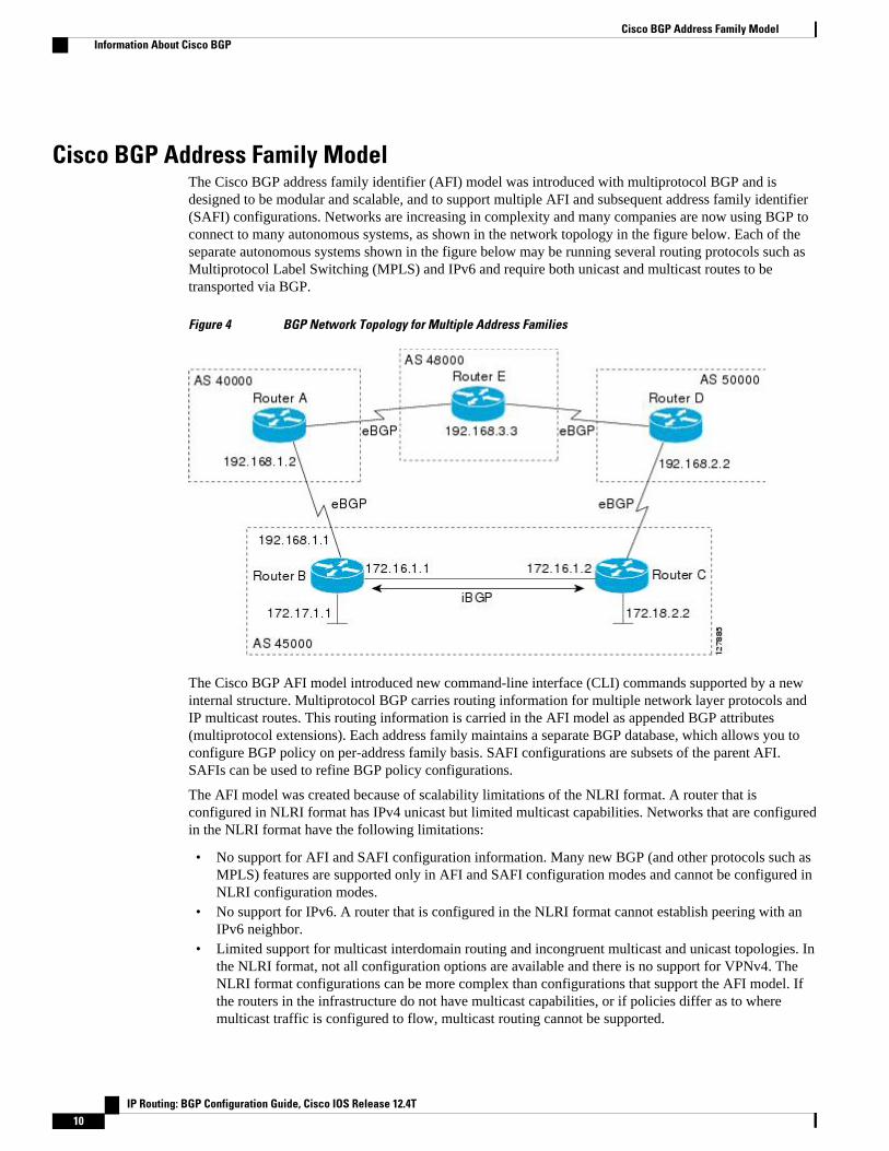
Cisco BGP Address Family ModelThe Cisco BGP address family identifier (AFI) model was introduced with multiprotocol BGP and isdesigned to be modular and scalable, and to support multiple AFI and subsequent address family identifier(SAFI) configurations. Networks are increasing in complexity and many companies are now using BGP toconnect to many autonomous systems, as shown in the network topology in the figure below. Each of theseparate autonomous systems shown in the figure below may be running several routing protocols such asMultiprotocol Label Switching (MPLS) and IPv6 and require both unicast and multicast routes to betransported via BGP.
Figure 4 BGP Network Topology for Multiple Address Families
The Cisco BGP AFI model introduced new command-line interface (CLI) commands supported by a newinternal structure. Multiprotocol BGP carries routing information for multiple network layer protocols andIP multicast routes. This routing information is carried in the AFI model as appended BGP attributes(multiprotocol extensions). Each address family maintains a separate BGP database, which allows you toconfigure BGP policy on per-address family basis. SAFI configurations are subsets of the parent AFI.SAFIs can be used to refine BGP policy configurations.
The AFI model was created because of scalability limitations of the NLRI format. A router that isconfigured in NLRI format has IPv4 unicast but limited multicast capabilities. Networks that are configuredin the NLRI format have the following limitations:
• No support for AFI and SAFI configuration information. Many new BGP (and other protocols such asMPLS) features are supported only in AFI and SAFI configuration modes and cannot be configured inNLRI configuration modes.
• No support for IPv6. A router that is configured in the NLRI format cannot establish peering with anIPv6 neighbor.
• Limited support for multicast interdomain routing and incongruent multicast and unicast topologies. Inthe NLRI format, not all configuration options are available and there is no support for VPNv4. TheNLRI format configurations can be more complex than configurations that support the AFI model. Ifthe routers in the infrastructure do not have multicast capabilities, or if policies differ as to wheremulticast traffic is configured to flow, multicast routing cannot be supported.
Cisco BGP Address Family Model Information About Cisco BGP
IP Routing: BGP Configuration Guide, Cisco IOS Release 12.4T10

The AFI model in multiprotocol BGP supports multiple AFIs and SAFIs, all NLRI-based commands andpolicy configurations, and is backward compatible with routers that support only the NLRI format. A routerthat is configured using the AFI model has the following features:
• AFI and SAFI information and configurations are supported. A router that is configured using the AFImodel can carry routing information for multiple network layer protocol address families (for example,IPv4 and IPv6).
• AFI configuration is similar in all address families, making the CLI syntax easier to use than the NLRIformat syntax.
• All BGP routing policy capabilities and commands are supported.• Congruent unicast and multicast topologies that have different policies (BGP filtering configurations)
are supported, as are incongruent multicast and unicast topologies.• CLNS is supported.• Interoperation between routers that support only the NLRI format (AFI-based networks are backward
compatible) is supported. This includes both IPv4 unicast and multicast NLRI peers.• Virtual Private Networks (VPNs) and VPN routing and forwarding (VRF) instances are supported.
Unicast IPv4 for VRFs can be configured from a specific address family IPv4 VRF; this configurationupdate is integrated into the BGP VPNv4 database.
Within a specific address family configuration mode, the question mark (?) online help function can beused to display supported commands. The BGP commands supported in address family configuration modeconfigure the same functionality as the BGP commands supported in router configuration mode; however,the BGP commands in router configuration mode configure functionality only for the IPv4 unicast addressprefix. To configure BGP commands and functionality for other address family prefixes (for example, theIPv4 multicast or IPv6 unicast address prefixes), you must enter address family configuration mode forthose address prefixes.
The BGP address family model consists of four address families in Cisco IOS software; IPv4, IPv6, CLNS,and VPNv4. In Cisco IOS Release 12.2(33)SRB, and later releases, support for the L2VPN address familywas introduced, and within the L2VPN address family the VPLS SAFI is supported. Within the IPv4 andIPv6 address families SAFIs such as Multicast Distribution Tree (MDT), tunnel, and VRF exist. The tablebelow shows the list of SAFIs supported by Cisco IOS software. To ensure compatibility between networksrunning all types of AFI and SAFI configuration, we recommend configuring BGP on Cisco IOS devicesusing the multiprotocol BGP address family model.
Table 4 SAFIs Supported by Cisco IOS Software
SAFI Field Value Description Reference
1 NLRI used for unicastforwarding.
RFC 2858
2 NLRI used for multicastforwarding.
RFC 2858
3 NLRI used for both unicast andmulticast forwarding.
RFC 2858
4 NLRI with MPLS labels. RFC 3107
64 Tunnel SAFI. draft-nalawade-kapoor-tunnel-safi -01.txt
Cisco BGP OverviewInformation About Cisco BGP
IP Routing: BGP Configuration Guide, Cisco IOS Release 12.4T 11

SAFI Field Value Description Reference
65 Virtual Private LAN Service(VPLS).
--
66 BGP MDT SAFI. draft-nalawade-idr-mdt-safi-00.txt
128 MPLS-labeled VPN address. RFC-ietf-l3vpn-rfc2547bis-03.txt
IPv4 Address FamilyThe IPv4 address family is used to identify routing sessions for protocols such as BGP that use standard IPversion 4 address prefixes. Unicast or multicast address prefixes can be specified within the IPv4 addressfamily. Routing information for address family IPv4 unicast is advertised by default when a BGP peer isconfigured unless the advertisement of unicast IPv4 information is explicitly turned off.
VRF instances can also be associated with IPv4 AFI configuration mode commands.
In Cisco IOS Release 12.0(28)S, the tunnel SAFI was introduced to support multipoint tunneling IPv4routing sessions. The tunnel SAFI is used to advertise the tunnel endpoints and the SAFI specific attributesthat contain the tunnel type and tunnel capabilities. Redistribution of tunnel endpoints into the BGP IPv4tunnel SAFI table occurs automatically when the tunnel address family is configured. However, peers needto be activated under the tunnel address family before the sessions can exchange tunnel information.
In Cisco IOS Release 12.0(29)S, the multicast distribution tree (MDT) SAFI was introduced to supportmulticast VPN architectures. The MDT SAFI is a transitive multicast capable connector attribute that isdefined as an IPv4 address family in BGP. The MDT address family session operates as a SAFI under theIPv4 multicast address family, and is configured on provider edge (PE) routers to establish VPN peeringsessions with customer edge (CE) routers that support inter-AS multicast VPN peering sessions.
IPv6 Address FamilyThe IPv6 address family is used to identify routing sessions for protocols such as BGP that use standardIPv6 address prefixes. Unicast or multicast address prefixes can be specified within the IPv6 addressfamily.
Note Routing information for address family IPv4 unicast is advertised by default when you configure a BGPpeer unless you explicitly turn off the advertisement of unicast IPv4 information.
CLNS Address FamilyThe CLNS address family is used to identify routing sessions for protocols such as BGP that use standardnetwork service access point (NSAP) address prefixes. Unicast address prefixes are the default when NSAPaddress prefixes are configured.
CLNS routes are used in networks where CLNS addresses are configured. This is typically atelecommunications Data Communications Network (DCN). Peering is established using IP addresses, butupdate messages contain CLNS routes.
For more details about configuring BGP support for CLNS, which provides the ability to scale CLNSnetworks, see the "Configuring Multiprotocol BGP (MP-BGP) support for CLNS" module.
IPv4 Address Family Information About Cisco BGP
IP Routing: BGP Configuration Guide, Cisco IOS Release 12.4T12

VPNv4 Address FamilyThe VPNv4 multicast address family is used to identify routing sessions for protocols such as BGP that usestandard VPN Version 4 address prefixes. Unicast address prefixes are the default when VPNv4 addressprefixes are configured. VPNv4 routes are the same as IPv4 routes, but VPNv4 routes have a routedescriptor (RD) prepended that allows replication of prefixes. It is possible to associate every different RDwith a different VPN. Each VPN needs its own set of prefixes.
Companies use an IP VPN as the foundation for deploying or administering value-added services includingapplications and data hosting network commerce, and telephony services to business customers.
In private LANs, IP-based intranets have fundamentally changed the way companies conduct theirbusiness. Companies are moving their business applications to their intranets to extend over a WAN.Companies are also addressing the needs of their customers, suppliers, and partners by using extranets (anintranet that encompasses multiple businesses). With extranets, companies reduce business process costs byfacilitating supply-chain automation, electronic data interchange (EDI), and other forms of networkcommerce. To take advantage of this business opportunity, service providers must have an IP VPNinfrastructure that delivers private network services to businesses over a public infrastructure.
VPNs, when used with MPLS, allow several sites to transparently interconnect through a service provider'snetwork. One service provider network can support several different IP VPNs. Each of these appears to itsusers as a private network, separate from all other networks. Within a VPN, each site can send IP packets toany other site in the same VPN. Each VPN is associated with one or more VPN VRFs. VPNv4 routes are asuperset of routes from all VRFs, and route injection is done per VRF under the specific VRF addressfamily. The router maintains a separate routing and Cisco Express Forwarding (CEF) table for each VRF.This prevents information from being sent outside the VPN and allows the same subnet to be used inseveral VPNs without causing duplicate IP address problems. The router using BGP distributes the VPNrouting information using the BGP extended communities.
The VPN address space is isolated from the global address space by design. BGP distributes reachabilityinformation for VPN-IPv4 prefixes for each VPN using the VPNv4 multiprotocol extensions to ensure thatthe routes for a given VPN are learned only by other members of that VPN, enabling members of the VPNto communicate with each other.
RFC 3107 specifies how to add label information to multiprotocol BGP address families using a SAFI. TheCisco IOS implementation of MPLS uses RFC 3107 to provide support for sending IPv4 routes with alabel. VPNv4 routes implicitly have a label associated with each route.
L2VPN Address FamilyIn Cisco IOS Release 12.2(33)SRB and later releases, support for the L2VPN address family is introduced.L2VPN is defined as a secure network that operates inside an unsecured network by using an encryptiontechnology such as IP security (IPsec) or Generic Routing Encapsulation (GRE). The L2VPN addressfamily is configured under BGP routing configuration mode, and within the L2VPN address family theVPLS subsequent address family identifier (SAFI) is supported.
BGP support for the L2VPN address family introduces a BGP-based autodiscovery mechanism to distributeL2VPN endpoint provisioning information. BGP uses a separate L2VPN routing information base (RIB) tostore endpoint provisioning information, which is updated each time any Layer 2 VFI is configured. Prefixand path information is stored in the L2VPN database, allowing BGP to make best-path decisions. WhenBGP distributes the endpoint provisioning information in an update message to all its BGP neighbors, theendpoint information is used to set up a pseudowire mesh to support L2VPN-based services.
The BGP autodiscovery mechanism facilitates the setting up of L2VPN services, which are an integral partof the Cisco IOS Virtual Private LAN Service (VPLS) feature. VPLS enables flexibility in deploying
VPNv4 Address FamilyInformation About Cisco BGP
IP Routing: BGP Configuration Guide, Cisco IOS Release 12.4T 13

services by connecting geographically dispersed sites as a large LAN over high-speed Ethernet in a robustand scalable IP MPLS network. For more details about VPLS, see the "VPLS Autodiscovery: BGP Based"feature.
Under L2VPN address family the following BGP command-line interface (CLI) commands are supported:
• bgp scan-time• bgp nexthop• neighbor activate• neighbor advertisement-interval• neighbor allowas-in• neighbor capability• neighbor inherit• neighbor peer-group• neighbor maximum-prefix• neighbor next-hop-self• neighbor next-hop-unchanged• neighbor remove-private-as• neighbor route-map• neighbor route-reflector-client• neighbor send-community• neighbor soft-reconfiguration• neighbor soo• neighbor weight
Note For route reflectors using L2VPNs, the neighbor next-hop-self and neighbor next-hop-unchangedcommands are not supported.
For route maps used within BGP, all commands related to prefix processing, tag processing, and automatedtag processing are ignored when used under L2VPN address family configuration. All other route mapcommands are supported.
BGP multipaths and confederations are not supported under the L2VPN address family.
For details on configuring BGP under the L2VPN address family, see the "BGP Support for the L2VPNAddress Family" feature in Cisco IOS Release 12.2(33)SRB.
BGP CLI Removal ConsiderationsBGP CLI configuration can become quite complex even in smaller BGP networks. If you need to removeany CLI configuration, you must consider all the implications of removing the CLI. Analyze the currentrunning configuration to determine the current BGP neighbor relationships, any address familyconsiderations, and even other routing protocols that are configured. Many BGP CLI commands affectother parts of the CLI configuration. For example, in the following configuration, a route map is used tomatch a BGP autonomous system number and then set the matched routes with another autonomous systemnumber for EIGRP:
route-map bgp-to-eigrp permit 10 match tag 50000 set tag 65000
BGP CLI Removal Considerations Information About Cisco BGP
IP Routing: BGP Configuration Guide, Cisco IOS Release 12.4T14
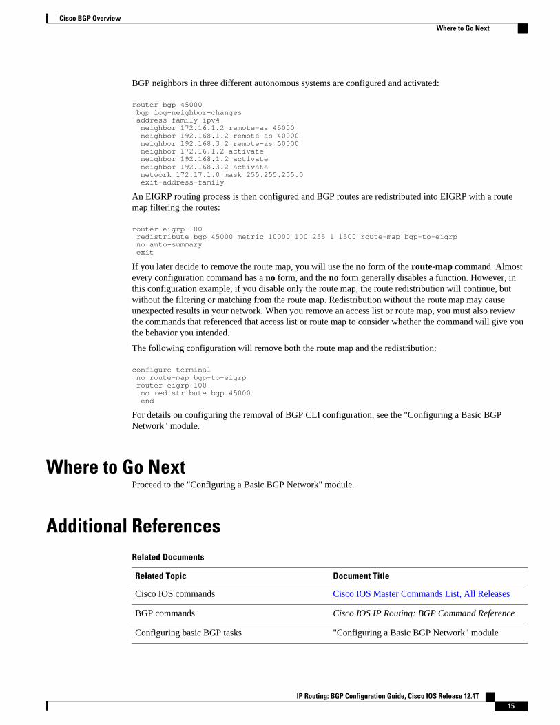
BGP neighbors in three different autonomous systems are configured and activated:
router bgp 45000 bgp log-neighbor-changes address-family ipv4 neighbor 172.16.1.2 remote-as 45000 neighbor 192.168.1.2 remote-as 40000 neighbor 192.168.3.2 remote-as 50000 neighbor 172.16.1.2 activate neighbor 192.168.1.2 activate neighbor 192.168.3.2 activate network 172.17.1.0 mask 255.255.255.0 exit-address-family
An EIGRP routing process is then configured and BGP routes are redistributed into EIGRP with a routemap filtering the routes:
router eigrp 100 redistribute bgp 45000 metric 10000 100 255 1 1500 route-map bgp-to-eigrp no auto-summary exit
If you later decide to remove the route map, you will use the no form of the route-map command. Almostevery configuration command has a no form, and the no form generally disables a function. However, inthis configuration example, if you disable only the route map, the route redistribution will continue, butwithout the filtering or matching from the route map. Redistribution without the route map may causeunexpected results in your network. When you remove an access list or route map, you must also reviewthe commands that referenced that access list or route map to consider whether the command will give youthe behavior you intended.
The following configuration will remove both the route map and the redistribution:
configure terminal no route-map bgp-to-eigrp router eigrp 100 no redistribute bgp 45000 end
For details on configuring the removal of BGP CLI configuration, see the "Configuring a Basic BGPNetwork" module.
Where to Go NextProceed to the "Configuring a Basic BGP Network" module.
Additional ReferencesRelated Documents
Related Topic Document Title
Cisco IOS commands Cisco IOS Master Commands List, All Releases
BGP commands Cisco IOS IP Routing: BGP Command Reference
Configuring basic BGP tasks "Configuring a Basic BGP Network" module
Cisco BGP OverviewWhere to Go Next
IP Routing: BGP Configuration Guide, Cisco IOS Release 12.4T 15
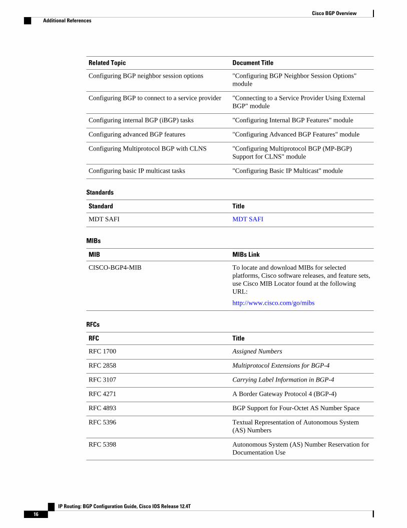
Related Topic Document Title
Configuring BGP neighbor session options "Configuring BGP Neighbor Session Options"module
Configuring BGP to connect to a service provider "Connecting to a Service Provider Using ExternalBGP" module
Configuring internal BGP (iBGP) tasks "Configuring Internal BGP Features" module
Configuring advanced BGP features "Configuring Advanced BGP Features" module
Configuring Multiprotocol BGP with CLNS "Configuring Multiprotocol BGP (MP-BGP)Support for CLNS" module
Configuring basic IP multicast tasks "Configuring Basic IP Multicast" module
Standards
Standard Title
MDT SAFI MDT SAFI
MIBs
MIB MIBs Link
CISCO-BGP4-MIB To locate and download MIBs for selectedplatforms, Cisco software releases, and feature sets,use Cisco MIB Locator found at the followingURL:
http://www.cisco.com/go/mibs
RFCs
RFC Title
RFC 1700 Assigned Numbers
RFC 2858 Multiprotocol Extensions for BGP-4
RFC 3107 Carrying Label Information in BGP-4
RFC 4271 A Border Gateway Protocol 4 (BGP-4)
RFC 4893 BGP Support for Four-Octet AS Number Space
RFC 5396 Textual Representation of Autonomous System(AS) Numbers
RFC 5398 Autonomous System (AS) Number Reservation forDocumentation Use
Cisco BGP Overview Additional References
IP Routing: BGP Configuration Guide, Cisco IOS Release 12.4T16

Technical Assistance
Description Link
The Cisco Support website provides extensiveonline resources, including documentation and toolsfor troubleshooting and resolving technical issueswith Cisco products and technologies.
To receive security and technical information aboutyour products, you can subscribe to variousservices, such as the Product Alert Tool (accessedfrom Field Notices), the Cisco Technical ServicesNewsletter, and Really Simple Syndication (RSS)Feeds.
Access to most tools on the Cisco Support websiterequires a Cisco.com user ID and password.
http://www.cisco.com/cisco/web/support/index.html
Feature Information for Cisco BGP OverviewThe following table provides release information about the feature or features described in this module.This table lists only the software release that introduced support for a given feature in a given softwarerelease train. Unless noted otherwise, subsequent releases of that software release train also support thatfeature.
Use Cisco Feature Navigator to find information about platform support and Cisco software image support.To access Cisco Feature Navigator, go to www.cisco.com/go/cfn. An account on Cisco.com is not required.
Cisco BGP OverviewFeature Information for Cisco BGP Overview
IP Routing: BGP Configuration Guide, Cisco IOS Release 12.4T 17

Table 5 Feature Information for Cisco BGP Overview
Feature Name Releases Feature Information
BGP Support for 4-Byte ASN 12.0(32)S12 12.0(32)SY812.0(33)S3 12.2(33)SRE12.2(33)XNE 12.2(33)SXI112.4(24)T 15.0(1)S Cisco IOSXE 3.1.0SG
The BGP Support for 4-ByteASN feature introduced supportfor 4-byte autonomous systemnumbers. Because of increaseddemand for autonomous systemnumbers, in January 2009 theIANA will start to allocate 4-byteautonomous system numbers inthe range from 65536 to4294967295.
In Cisco IOS Release12.0(32)SY8, 12.0(33)S3,12.2(33)SRE, 12.2(33)XNE, and12.2(33)SXI1, the Ciscoimplementation of 4-byteautonomous system numbers usesasplain as the default regularexpression match and outputdisplay format for autonomoussystem numbers, but you canconfigure 4-byte autonomoussystem numbers in both theasplain format and the asdotformat as described in RFC 5396.To change the default regularexpression match and outputdisplay of 4-byte autonomoussystem numbers to asdot format,use the bgp asnotation dotcommand.
In Cisco IOS Release12.0(32)S12, and 12.4(24)T, theCisco implementation of 4-byteautonomous system numbers usesasdot as the only configurationformat, regular expression match,and output display, with noasplain support.
The following commands wereintroduced or modified by thisfeature: bgp asnotation dot, bgpconfederation identifier, bgpconfederation peers, all clear ipbgpcommands that configure anautonomous system number, ipas-path access-list, ipextcommunity-list, match
Cisco BGP Overview Feature Information for Cisco BGP Overview
IP Routing: BGP Configuration Guide, Cisco IOS Release 12.4T18
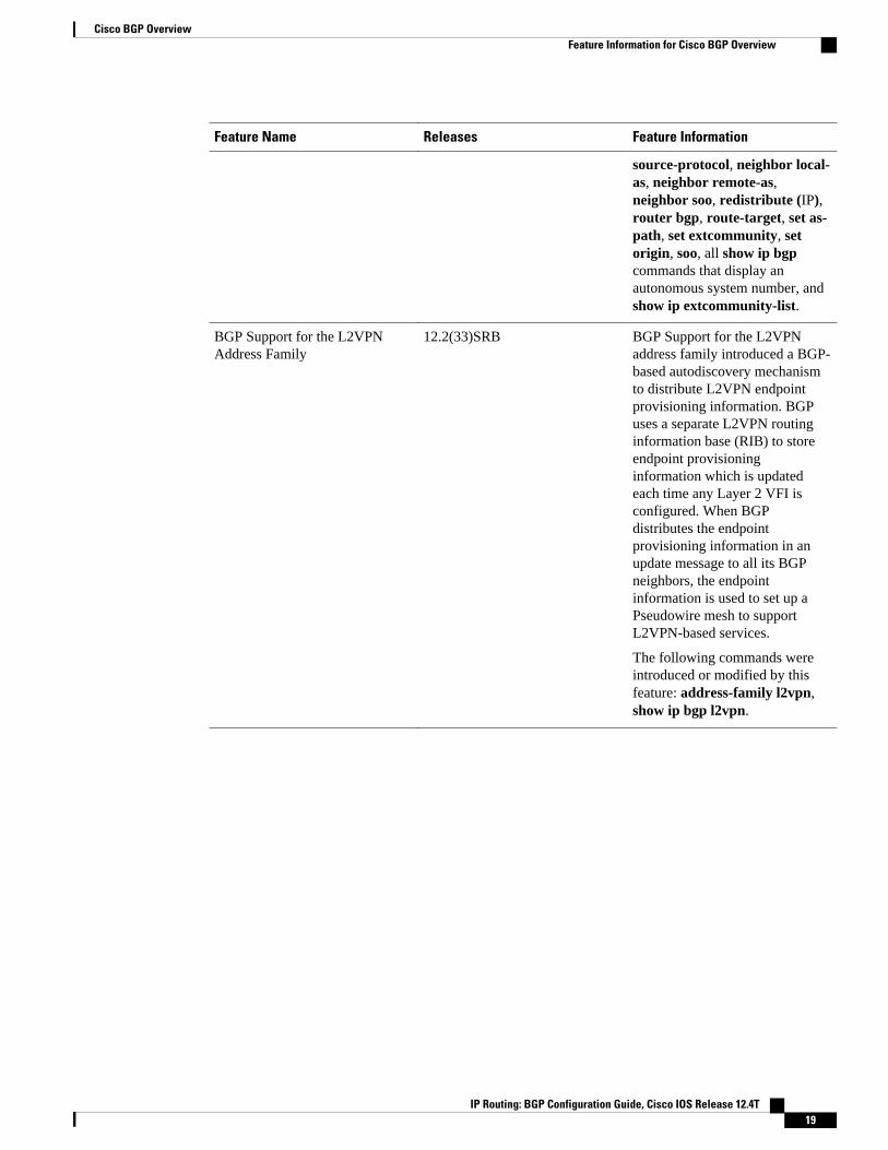
Feature Name Releases Feature Information
source-protocol, neighbor local-as, neighbor remote-as,neighbor soo, redistribute (IP),router bgp, route-target, set as-path, set extcommunity, setorigin, soo, all show ip bgpcommands that display anautonomous system number, andshow ip extcommunity-list.
BGP Support for the L2VPNAddress Family
12.2(33)SRB BGP Support for the L2VPNaddress family introduced a BGP-based autodiscovery mechanismto distribute L2VPN endpointprovisioning information. BGPuses a separate L2VPN routinginformation base (RIB) to storeendpoint provisioninginformation which is updatedeach time any Layer 2 VFI isconfigured. When BGPdistributes the endpointprovisioning information in anupdate message to all its BGPneighbors, the endpointinformation is used to set up aPseudowire mesh to supportL2VPN-based services.
The following commands wereintroduced or modified by thisfeature: address-family l2vpn,show ip bgp l2vpn.
Cisco BGP OverviewFeature Information for Cisco BGP Overview
IP Routing: BGP Configuration Guide, Cisco IOS Release 12.4T 19
Feature Name Releases Feature Information
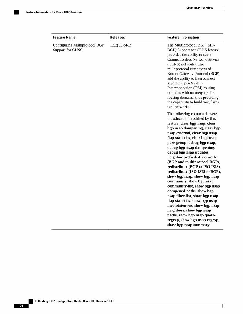
Configuring Multiprotocol BGPSupport for CLNS
12.2(33)SRB The Multiprotocol BGP (MP-BGP) Support for CLNS featureprovides the ability to scaleConnectionless Network Service(CLNS) networks. Themultiprotocol extensions ofBorder Gateway Protocol (BGP)add the ability to interconnectseparate Open SystemInterconnection (OSI) routingdomains without merging therouting domains, thus providingthe capability to build very largeOSI networks.
The following commands wereintroduced or modified by thisfeature: clear bgp nsap, clearbgp nsap dampening, clear bgpnsap external, clear bgp nsapflap-statistics, clear bgp nsappeer-group, debug bgp nsap,debug bgp nsap dampening,debug bgp nsap updates,neighbor prefix-list, network(BGP and multiprotocol BGP),redistribute (BGP to ISO ISIS),redistribute (ISO ISIS to BGP),show bgp nsap, show bgp nsapcommunity, show bgp nsapcommunity-list, show bgp nsapdampened-paths, show bgpnsap filter-list, show bgp nsapflap-statistics, show bgp nsapinconsistent-as, show bgp nsapneighbors, show bgp nsappaths, show bgp nsap quote-regexp, show bgp nsap regexp,show bgp nsap summary.
Cisco BGP Overview Feature Information for Cisco BGP Overview
IP Routing: BGP Configuration Guide, Cisco IOS Release 12.4T20
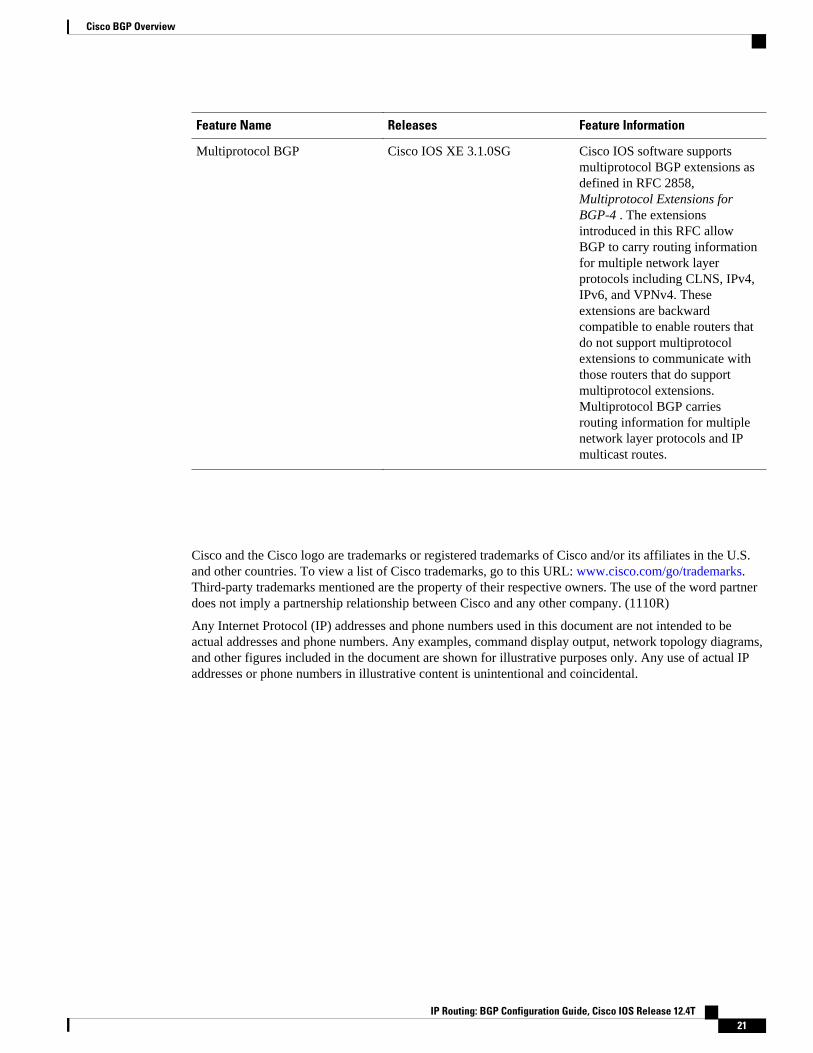
Feature Name Releases Feature Information
Multiprotocol BGP Cisco IOS XE 3.1.0SG Cisco IOS software supportsmultiprotocol BGP extensions asdefined in RFC 2858,Multiprotocol Extensions forBGP-4 . The extensionsintroduced in this RFC allowBGP to carry routing informationfor multiple network layerprotocols including CLNS, IPv4,IPv6, and VPNv4. Theseextensions are backwardcompatible to enable routers thatdo not support multiprotocolextensions to communicate withthose routers that do supportmultiprotocol extensions.Multiprotocol BGP carriesrouting information for multiplenetwork layer protocols and IPmulticast routes.
Cisco and the Cisco logo are trademarks or registered trademarks of Cisco and/or its affiliates in the U.S.and other countries. To view a list of Cisco trademarks, go to this URL: www.cisco.com/go/trademarks.Third-party trademarks mentioned are the property of their respective owners. The use of the word partnerdoes not imply a partnership relationship between Cisco and any other company. (1110R)
Any Internet Protocol (IP) addresses and phone numbers used in this document are not intended to beactual addresses and phone numbers. Any examples, command display output, network topology diagrams,and other figures included in the document are shown for illustrative purposes only. Any use of actual IPaddresses or phone numbers in illustrative content is unintentional and coincidental.
Cisco BGP Overview
IP Routing: BGP Configuration Guide, Cisco IOS Release 12.4T 21

BGP CLI Removal Considerations
IP Routing: BGP Configuration Guide, Cisco IOS Release 12.4T22

Configuring Multiprotocol BGP (MP-BGP)Support for CLNS
This module describes configuration tasks to configure multiprotocol BGP (MP-BGP) support for CLNS,which provides the ability to scale Connectionless Network Service (CLNS) networks. The multiprotocolextensions of Border Gateway Protocol (BGP) add the ability to interconnect separate Open SystemInterconnection (OSI) routing domains without merging the routing domains, thus providing the capabilityto build very large OSI networks.
• Finding Feature Information, page 23• Restrictions for Configuring MP-BGP Support for CLNS, page 23• Information About Configuring MP-BGP Support for CLNS, page 24• How to Configure MP-BGP Support for CLNS, page 27• Configuration Examples for MP-BGP Support for CLNS, page 51• Additional References, page 60• Feature Information for Configuring MP-BGP Support for CLNS, page 61• Glossary, page 63
Finding Feature InformationYour software release may not support all the features documented in this module. For the latest featureinformation and caveats, see the release notes for your platform and software release. To find informationabout the features documented in this module, and to see a list of the releases in which each feature issupported, see the Feature Information Table at the end of this document.
Use Cisco Feature Navigator to find information about platform support and Cisco software image support.To access Cisco Feature Navigator, go to www.cisco.com/go/cfn. An account on Cisco.com is not required.
Restrictions for Configuring MP-BGP Support for CLNSThe configuration of MP-BGP support for CLNS does not support the creation and use of BGPconfederations within the CLNS network. We recommend the use of route reflectors to address the issue ofa large internal BGP mesh.
BGP extended communities are not supported by this feature.
The following BGP commands are not supported by this feature:
• auto-summary• neighbor advertise-map
IP Routing: BGP Configuration Guide, Cisco IOS Release 12.4T 23
• neighbor distribute-list• neighbor soft-reconfiguration• neighbor unsuppress-map
Information About Configuring MP-BGP Support for CLNS• Address Family Routing Information, page 24
• Design Features of MP-BGP Support for CLNS, page 24
• Generic BGP CLNS Network Topology, page 24
• DCN Network Topology, page 26
• Benefits of MP-BGP Support for CLNS, page 27
Address Family Routing InformationBy default, commands entered under the router bgp command apply to the IPv4 address family. This willcontinue to be the case unless you enter the no bgp default ipv4-unicast command as the first commandunder the router bgp command. The no bgp default ipv4-unicast command is configured on the router todisable the default behavior of the BGP routing process exchanging IPv4 addressing information with BGPneighbor routers.
Design Features of MP-BGP Support for CLNSThe configuration of MP-BGP support for CLNS allows BGP to be used as an interdomain routing protocolin networks that use CLNS as the network-layer protocol. This feature was developed to solve a scalingissue with a data communications network (DCN) where large numbers of network elements are managedremotely. For details about the DCN issues and how to implement this feature in a DCN topology, see the DCN Network Topology, page 26."
BGP, as an Exterior Gateway Protocol, was designed to handle the volume of routing informationgenerated by the Internet. Network administrators can control the BGP routing information because BGPneighbor relationships (peering) are manually configured and routing updates use incremental broadcasts.Some interior routing protocols such as Intermediate System-to-Intermediate System (IS-IS), in contrast,use a form of automatic neighbor discovery technique and broadcast updates at regular intervals.
CLNS uses network service access point (NSAP) addresses to identify all its network elements. Using theBGP address-family support, NSAP address prefixes can be transported using BGP. In CLNS, BGPprefixes are inserted into the CLNS Level 2 prefix table. This functionality allows BGP to be used as aninterdomain routing protocol between separate CLNS routing domains.
Implementing BGP in routers at the edge of each internal network means that the existing interior protocolsneed not be changed, minimizing disruption in the network.
Generic BGP CLNS Network TopologyThe figure below shows a generic BGP CLNS network containing nine routers that are grouped into fourdifferent autonomous systems (in BGP terminology) or routing domains (in OSI terminology). To avoid
Address Family Routing Information Information About Configuring MP-BGP Support for CLNS
IP Routing: BGP Configuration Guide, Cisco IOS Release 12.4T24

confusion, we will use the BGP terminology of autonomous systems because each autonomous system isnumbered and therefore more easily identified in the diagram and in the configuration discussion.
Figure 5 Components in a Generic BGP CLNS Network
Within each autonomous system, IS-IS is used as the intradomain routing protocol. Between autonomoussystems, BGP and its multiprotocol extensions are used as the interdomain routing protocol. Each router isrunning either a BGP or Level 2 IS-IS routing process. To facilitate this feature, the BGP routers are alsorunning a Level 2 IS-IS process. Although the links are not shown in the figure, each Level 2 IS-IS router isconnected to multiple Level 1 IS-IS routers that are, in turn, connected to multiple CLNS networks.
Each autonomous system in this example is configured to demonstrate various BGP features and how thesefeatures work with CLNS to provide a scalable interdomain routing solution. In the figure above, theautonomous system AS65101 has a single Level 2 IS-IS router, R1, and is connected to just one otherautonomous system, AS65202. Connectivity to the rest of the network is provided by R2, and a defaultroute is generated for R1 to send to R2 all packets with destination NSAP addresses outside of AS65101.
In AS65202 there are two routers, R2 and R3, both with different external BGP (eBGP) neighbors. RoutersR2 and R3 are configured to run internal BGP (iBGP) over the internal connection between them.
AS65303 shows how the use of BGP peer groups and route reflection can minimize the need for TCPconnections between routers. Fewer connections between routers simplifies the network design and theamount of traffic in the network.
AS65404 shows how to use redistribution to communicate network reachability information to a Level 2IS-IS router that is not running BGP.
The configuration tasks and examples are based on the generic network design shown in the figure above.Configurations for all the routers in the figure above are listed in .
Configuring Multiprotocol BGP (MP-BGP) Support for CLNSInformation About Configuring MP-BGP Support for CLNS
IP Routing: BGP Configuration Guide, Cisco IOS Release 12.4T 25

DCN Network TopologyThe Multiprotocol BGP (MP-BGP) Support for CLNS feature can benefit a DCN managing a large numberof remote SONET rings. SONET is typically used by telecommunications companies to send data overfiber-optic networks.
The figure below shows some components of a DCN network. To be consistent with the BGP terminology,the figure contains labels to indicate three autonomous systems instead of routing domains. The networkelements--designated by NE in Figure 2--of a SONET ring are managed by OSI protocols such as FileTransfer, Access, and Management (FTAM) and Common Management Information Protocol (CMIP).FTAM and CMIP run over the CLNS network-layer protocol, which means that the routers providingconnectivity must run an OSI routing protocol.
Figure 6 Components in a DCN Network
IS-IS is a link-state protocol used in this example to route CLNS. Each routing node (networking device) iscalled an intermediate system (IS). The network is divided into areas defined as a collection of routingnodes. Routing within an area is referred to as Level 1 routing. Routing between areas involves Level 2routing. Routers that link a Level 1 area with a Level 2 area are defined as Level 1-2 routers. A networkelement that connects to the Level 2 routers that provide a path to the DCN core is represented by agateway network element--GNE in Figure 2. The network topology here is a point-to-point link betweeneach network element router. In this example, a Level 1 IS-IS router is called an NE router.
Smaller Cisco routers such as the Cisco 2600 series were selected to run as the Level 1-2 routers becauseshelf space in the central office (CO) of a service provider is very expensive. A Cisco 2600 series router
DCN Network Topology Information About Configuring MP-BGP Support for CLNS
IP Routing: BGP Configuration Guide, Cisco IOS Release 12.4T26

has limited processing power if it is acting as the Level 1 router for four or five different Level 1 areas. Thenumber of Level 1 areas under this configuration is limited to about 200. The entire Level 2 network is alsolimited by the speed of the slowest Level 2 router.
To provide connectivity between NE routers, in-band signaling is used. The in-band signaling is carried inthe SONET/Synchronous Digital Hierarchy (SDH) frame on the data communications channel (DCC). TheDCC is a 192-KB channel, which is a very limited amount of bandwidth for the management traffic. Due tothe limited signaling bandwidth between network elements and the limited amount of processing power andmemory in the NE routers running IS-IS, each area is restricted to a maximum number of 30 to 40 routers.On average, each SONET ring consists of 10 to 15 network elements.
With a maximum of 200 areas containing 10 to 15 network elements per area, the total number of networkelement routers in a single autonomous system must be fewer than 3000. Service providers are looking toimplement over 10,000 network elements as their networks grow, but the potential number of networkelements in an area is limited. The current solution is to break down the DCN into a number of smallerautonomous systems and connect them using static routes or ISO Interior Gateway Routing Protocol(IGRP). ISO IGRP is a proprietary protocol that can limit future equipment implementation options. Staticrouting does not scale because the growth in the network can exceed the ability of a network administratorto maintain the static routes. BGP has been shown to scale to over 100,000 routes.
To implement the Multiprotocol BGP (MP-BGP) Support for CLNS feature in this example, configureBGP to run on each router in the DCN core network--AS64800 in Figure 2--to exchange routinginformation between all the autonomous systems. In the autonomous systems AS64600 and AS64700, onlythe Level 2 routers will run BGP. BGP uses TCP to communicate with BGP-speaking neighbor routers,which means that both an IP-addressed network and an NSAP-addressed network must be configured tocover all the Level 2 IS-IS routers in the autonomous systems AS64600 and AS64700 and all the routers inthe DCN core network.
Assuming that each autonomous system--for example, AS64600 and AS64700 in Figure 2--remains thesame size with up to 3000 nodes, we can demonstrate how large DCN networks can be supported with thisfeature. Each autonomous system advertises one address prefix to the core autonomous system. Eachaddress prefix can have two paths associated with it to provide redundancy because there are two linksbetween each autonomous system and the core autonomous system. BGP has been shown to support100,000 routes, so the core autonomous system can support many other directly linked autonomoussystems because each autonomous system generates only a few routes. We can assume that the coreautonomous system can support about 2000 directly linked autonomous systems. With the hub-and-spokedesign where each autonomous system is directly linked to the core autonomous system, and not acting as atransit autonomous system, the core autonomous system can generate a default route to each linkedautonomous system. Using the default routes, the Level 2 routers in the linked autonomous systems processonly a small amount of additional routing information. Multiplying the 2000 linked autonomous systems bythe 3000 nodes within each autonomous system could allow up to 6 million network elements.
Benefits of MP-BGP Support for CLNSThe Multiprotocol BGP (MP-BGP) Support for CLNS feature adds the ability to interconnect separate OSIrouting domains without merging the routing domains, which provides the capability to build very largeOSI networks. The benefits of using this feature are not confined to DCN networks, and can beimplemented to help scale any network using OSI routing protocols with CLNS.
How to Configure MP-BGP Support for CLNS
Benefits of MP-BGP Support for CLNSHow to Configure MP-BGP Support for CLNS
IP Routing: BGP Configuration Guide, Cisco IOS Release 12.4T 27

This section contains the following procedures. It may not be necessary to go through each procedure foryour particular network. You must perform the steps in the required procedures, but all other proceduresare done as required for your network.
• Configuring and Activating a BGP Neighbor to Support CLNS, page 28
• Configuring an IS-IS Routing Process, page 30
• Configuring Interfaces That Connect to BGP Neighbors, page 31
• Configuring Interfaces Connected to the Local OSI Routing Domain, page 33
• Advertising Networking Prefixes, page 34
• Redistributing Routes from BGP into IS-IS, page 37
• Redistributing Routes from IS-IS into BGP, page 38
• Configuring BGP Peer Groups and Route Reflectors, page 40
• Filtering Inbound Routes Based on NSAP Prefixes, page 42
• Filtering Outbound BGP Updates Based on NSAP Prefixes, page 43
• Originating Default Routes for a Neighboring Routing Domain, page 46
• Verifying MP-BGP Support for CLNS, page 48
• Troubleshooting MP-BGP Support for CLNS, page 50
Configuring and Activating a BGP Neighbor to Support CLNSTo configure and activate a BGP routing process and an associated BGP neighbor (peer) to support CLNS,perform the steps in this procedure.
SUMMARY STEPS
1. enable
2. configure terminal
3. router bgp as-number
4. no bgp default ipv4-unicast
5. neighbor {ip-address | peer-group-name} remote-as as-number
6. address-family nsap [unicast]
7. neighbor ip-address activate
8. end
DETAILED STEPS
Command or Action Purpose
Step 1 enable
Example:
Router> enable
Enables privileged EXEC mode.
• Enter your password if prompted.
Configuring and Activating a BGP Neighbor to Support CLNS How to Configure MP-BGP Support for CLNS
IP Routing: BGP Configuration Guide, Cisco IOS Release 12.4T28

Command or Action Purpose
Step 2 configure terminal
Example:
Router# configure terminal
Enters global configuration mode.
Step 3 router bgp as-number
Example:
Router(config)# router bgp 65101
Configures a BGP routing process and enters router configuration mode.
• The as-number argument identifies the autonomous system in whichthe router resides. Valid values are from 0 to 65535. Privateautonomous system numbers that can be used in internal networksrange from 64512 to 65535.
Step 4 no bgp default ipv4-unicast
Example:
Router(config-router)# no bgp default ipv4-unicast
Disables the default behavior of the BGP routing process exchanging IPv4addressing information with BGP neighbor routers.
Step 5 neighbor {ip-address | peer-group-name}remote-as as-number
Example:
Router(config-router)# neighbor 10.1.2.2 remote-as 64202
Adds an IP address or peer group name of the BGP neighbor in thespecified autonomous system to the BGP neighbor table of the localrouter.
Step 6 address-family nsap [unicast]
Example:
Router(config-router)# address-family nsap
Specifies the NSAP address family and enters address familyconfiguration mode.
• The optional unicast keyword specifies the NSAP unicast addressprefixes. By default, the router is placed in configuration mode forthe unicast NSAP address family if the unicast keyword is notspecified with the address-family nsap command.
Step 7 neighbor ip-address activate
Example:
Router(config-router-af)# neighbor 10.1.2.2 activate
Enables the BGP neighbor to exchange prefixes for the NSAP addressfamily with the local router.
Note If you have configured a peer group as a BGP neighbor, you do notuse this command because peer groups are automatically activatedwhen any peer group parameter is configured.
Configuring Multiprotocol BGP (MP-BGP) Support for CLNSHow to Configure MP-BGP Support for CLNS
IP Routing: BGP Configuration Guide, Cisco IOS Release 12.4T 29

Command or Action Purpose
Step 8 end
Example:
Router(config-router-af)# end
Exits address family configuration mode and returns to privileged EXECmode.
Configuring an IS-IS Routing ProcessWhen an integrated IS-IS routing process is configured, the first instance of the IS-IS routing processconfigured is by default a Level 1-2 (intra-area and interarea) router. All subsequent IS-IS routingprocesses on a network running CLNS are configured as Level 1. All subsequent IS-IS routing processes ona network running IP are configured as Level-1-2. To use the Multiprotocol BGP (MP-BGP) Support forCLNS feature, configure a Level 2 routing process.
To configure an IS-IS routing process and assign it as a Level-2-only process, perform the steps in thisprocedure.
SUMMARY STEPS
1. enable
2. configure terminal
3. router isis area-tag
4. net network-entity-title
5. is-type [level-1 | level-1-2 | level-2-only]
6. end
DETAILED STEPS
Command or Action Purpose
Step 1 enable
Example:
Router> enable
Enables privileged EXEC mode.
• Enter your password if prompted.
Step 2 configure terminal
Example:
Router# configure terminal
Enters global configuration mode.
Configuring an IS-IS Routing Process How to Configure MP-BGP Support for CLNS
IP Routing: BGP Configuration Guide, Cisco IOS Release 12.4T30

Command or Action Purpose
Step 3 router isis area-tag
Example:
Router(config)# router isis osi-as-101
Configures an IS-IS routing process and enters router configurationmode for the specified routing process.
• The area-tag argument is a meaningful name for a routingprocess. It must be unique among all IP and CLNS routingprocesses for a given router.
Step 4 net network-entity-title
Example:
Router(config-router)# net 49.0101.1111.1111.1111.1111.00
Configures a network entity title (NET) for the routing process. Ifyou are configuring multiarea IS-IS, you must specify a NET foreach routing process.
Step 5 is-type [level-1 | level-1-2 | level-2-only]
Example:
Router(config-router)# is-type level-1
Configures the router to act as a Level 1 (intra-area) router, as botha Level 1 router and a Level 2 (interarea) router, or as an interarearouter only.
• In multiarea IS-IS configurations, the first instance of the IS-IS routing process configured is by default a Level 1-2 (intra-area and interarea) router. All subsequent IS-IS routingprocesses on a network running CLNS are configured as Level1. All subsequent IS-IS routing processes on a networkrunning IP are configured as Level-1-2.
Step 6 end
Example:
Router(config-router)# end
Exits router configuration mode and returns to privileged EXECmode.
Configuring Interfaces That Connect to BGP NeighborsWhen a router running IS-IS is directly connected to an eBGP neighbor, the interface between the twoeBGP neighbors is activated using the clns enable command, which allows CLNS packets to be forwardedacross the interface. The clns enable command activates the End System-to-Intermediate System (ES-IS)protocol to search for neighboring OSI systems.
Note Running IS-IS across the same interface that is connected to an eBGP neighbor can lead to undesirableresults if the two OSI routing domains merge into a single domain.
When a neighboring OSI system is found, BGP checks that it is also an eBGP neighbor configured for theNSAP address family. If both the preceding conditions are met, BGP creates a special BGP neighbor routein the CLNS Level 2 prefix routing table. The special BGP neighbor route is automatically redistributed into the Level 2 routing updates so that all other Level 2 IS-IS routers in the local OSI routing domain knowhow to reach this eBGP neighbor.
Configuring Interfaces That Connect to BGP NeighborsHow to Configure MP-BGP Support for CLNS
IP Routing: BGP Configuration Guide, Cisco IOS Release 12.4T 31

To configure interfaces that are being used to connect with eBGP neighbors, perform the steps in thisprocedure. These interfaces will normally be directly connected to their eBGP neighbor.
SUMMARY STEPS
1. enable
2. configure terminal
3. interface type number
4. ip address ip-address mask
5. clns enable
6. no shutdown
7. end
DETAILED STEPS
Command or Action Purpose
Step 1 enable
Example:
Router> enable
Enables privileged EXEC mode.
• Enter your password if prompted.
Step 2 configure terminal
Example:
Router# configure terminal
Enters global configuration mode.
Step 3 interface type number
Example:
Router(config)# interface serial 2/0
Specifies the interface type and number and enters interfaceconfiguration mode.
Step 4 ip address ip-address mask
Example:
Router(config-if)# ip address 10.1.2.2 255.255.255.0
Configures the interface with an IP address.
Step 5 clns enable
Example:
Router(config-if)# clns enable
Specifies that CLNS packets can be forwarded across thisinterface. The ES-IS protocol is activated and starts tosearch for adjacent OSI systems.
Configuring Multiprotocol BGP (MP-BGP) Support for CLNS How to Configure MP-BGP Support for CLNS
IP Routing: BGP Configuration Guide, Cisco IOS Release 12.4T32

Command or Action Purpose
Step 6 no shutdown
Example:
Router(config-if)# no shutdown
Turns on the interface.
Step 7 end
Example:
Router(config-if)# end
Exits interface configuration mode and returns to privilegedEXEC mode.
Configuring Interfaces Connected to the Local OSI Routing DomainTo configure interfaces that are connected to the local OSI routing domain, perform the steps in thisprocedure.
SUMMARY STEPS
1. enable
2. configure terminal
3. interface type number
4. ip address ip-address mask
5. clns router isis area-tag
6. ip router isis area-tag
7. no shutdown
8. end
DETAILED STEPS
Command or Action Purpose
Step 1 enable
Example:
Router> enable
Enables privileged EXEC mode.
• Enter your password if prompted.
Step 2 configure terminal
Example:
Router# configure terminal
Enters global configuration mode.
Configuring Interfaces Connected to the Local OSI Routing DomainHow to Configure MP-BGP Support for CLNS
IP Routing: BGP Configuration Guide, Cisco IOS Release 12.4T 33
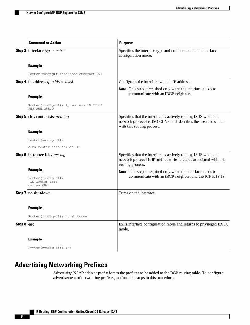
Command or Action Purpose
Step 3 interface type number
Example:
Router(config)# interface ethernet 0/1
Specifies the interface type and number and enters interfaceconfiguration mode.
Step 4 ip address ip-address mask
Example:
Router(config-if)# ip address 10.2.3.1 255.255.255.0
Configures the interface with an IP address.
Note This step is required only when the interface needs tocommunicate with an iBGP neighbor.
Step 5 clns router isis area-tag
Example:
Router(config-if)# clns router isis osi-as-202
Specifies that the interface is actively routing IS-IS when thenetwork protocol is ISO CLNS and identifies the area associatedwith this routing process.
Step 6 ip router isis area-tag
Example:
Router(config-if)# ip router isis osi-as-202
Specifies that the interface is actively routing IS-IS when thenetwork protocol is IP and identifies the area associated with thisrouting process.
Note This step is required only when the interface needs tocommunicate with an iBGP neighbor, and the IGP is IS-IS.
Step 7 no shutdown
Example:
Router(config-if)# no shutdown
Turns on the interface.
Step 8 end
Example:
Router(config-if)# end
Exits interface configuration mode and returns to privileged EXECmode.
Advertising Networking PrefixesAdvertising NSAP address prefix forces the prefixes to be added to the BGP routing table. To configureadvertisement of networking prefixes, perform the steps in this procedure.
Advertising Networking Prefixes How to Configure MP-BGP Support for CLNS
IP Routing: BGP Configuration Guide, Cisco IOS Release 12.4T34

SUMMARY STEPS
1. enable
2. configure terminal
3. router bgp as-number
4. no bgp default ipv4-unicast
5. neighbor {ip-address | peer-group-name} remote-as as-number
6. address-family nsap [unicast]
7. network nsap-prefix [route-map map-tag]
8. neighbor ip-address activate
9. end
DETAILED STEPS
Command or Action Purpose
Step 1 enable
Example:
Router> enable
Enables privileged EXEC mode.
• Enter your password if prompted.
Step 2 configure terminal
Example:
Router# configure terminal
Enters global configuration mode.
Step 3 router bgp as-number
Example:
Router(config)# router bgp 65101
Configures a BGP routing process and enters routerconfiguration mode for the specified routing process.
Step 4 no bgp default ipv4-unicast
Example:
Router(config-router)# no bgp default ipv4-unicast
Disables the default behavior of the BGP routing processexchanging IPv4 addressing information with BGP neighborrouters.
Configuring Multiprotocol BGP (MP-BGP) Support for CLNSHow to Configure MP-BGP Support for CLNS
IP Routing: BGP Configuration Guide, Cisco IOS Release 12.4T 35

Command or Action Purpose
Step 5 neighbor {ip-address | peer-group-name} remote-asas-number
Example:
Router(config-router)# neighbor 10.1.2.2 remote-as 64202
Adds an IP address or peer group name of the BGP neighbor inthe specified autonomous system to the BGP neighbor table ofthe local router.
Step 6 address-family nsap [unicast]
Example:
Router(config-router)# address-family nsap
Specifies the NSAP address family and enters address familyconfiguration mode.
• The optional unicast keyword specifies the NSAP unicastaddress prefixes. By default, the router is placed in unicastNSAP address family configuration mode if the unicastkeyword is not specified with the address-family nsapcommand.
Step 7 network nsap-prefix [route-map map-tag]
Example:
Router(config-router-af)# network 49.0101.1111.1111.1111.1111.00
Advertises a single prefix of the local OSI routing domain andenters it in the BGP routing table.
Note It is possible to advertise a single prefix, in which casethis prefix could be the unique NSAP address prefix ofthe local OSI routing domain. Alternatively, multiplelonger prefixes, each covering a small portion of the OSIrouting domain, can be used to selectively advertisedifferent areas.
• The advertising of NSAP address prefixes can becontrolled by using the optional route-map keyword. If noroute map is specified, all NSAP address prefixes areredistributed.
Step 8 neighbor ip-address activate
Example:
Router(config-router-af) neighbor 10.1.2.2 activate
Specifies that NSAP routing information will be sent to thespecified BGP neighbor.
Note See the description of the neighbor command in thedocuments listed in the "Additional References" for moredetails on the use of this command.
Step 9 end
Example:
Router(config-router-af)# end
Exits address family configuration mode and returns toprivileged EXEC mode.
Configuring Multiprotocol BGP (MP-BGP) Support for CLNS How to Configure MP-BGP Support for CLNS
IP Routing: BGP Configuration Guide, Cisco IOS Release 12.4T36
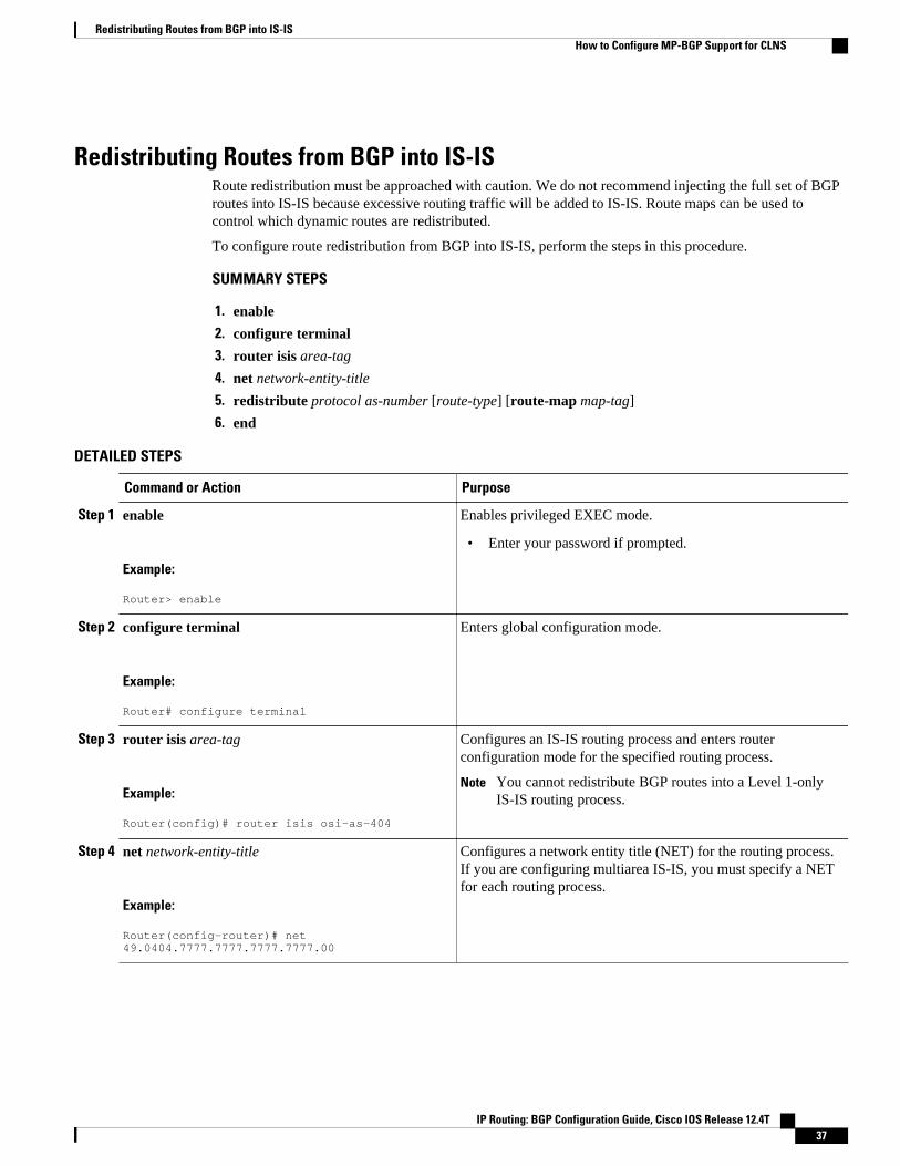
Redistributing Routes from BGP into IS-ISRoute redistribution must be approached with caution. We do not recommend injecting the full set of BGProutes into IS-IS because excessive routing traffic will be added to IS-IS. Route maps can be used tocontrol which dynamic routes are redistributed.
To configure route redistribution from BGP into IS-IS, perform the steps in this procedure.
SUMMARY STEPS
1. enable
2. configure terminal
3. router isis area-tag
4. net network-entity-title
5. redistribute protocol as-number [route-type] [route-map map-tag]
6. end
DETAILED STEPS
Command or Action Purpose
Step 1 enable
Example:
Router> enable
Enables privileged EXEC mode.
• Enter your password if prompted.
Step 2 configure terminal
Example:
Router# configure terminal
Enters global configuration mode.
Step 3 router isis area-tag
Example:
Router(config)# router isis osi-as-404
Configures an IS-IS routing process and enters routerconfiguration mode for the specified routing process.
Note You cannot redistribute BGP routes into a Level 1-onlyIS-IS routing process.
Step 4 net network-entity-title
Example:
Router(config-router)# net 49.0404.7777.7777.7777.7777.00
Configures a network entity title (NET) for the routing process.If you are configuring multiarea IS-IS, you must specify a NETfor each routing process.
Redistributing Routes from BGP into IS-ISHow to Configure MP-BGP Support for CLNS
IP Routing: BGP Configuration Guide, Cisco IOS Release 12.4T 37
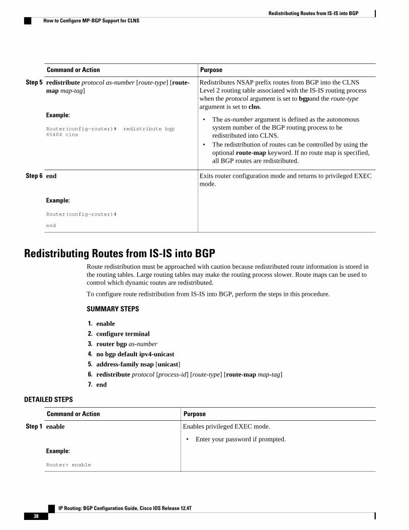
Command or Action Purpose
Step 5 redistribute protocol as-number [route-type] [route-map map-tag]
Example:
Router(config-router)# redistribute bgp 65404 clns
Redistributes NSAP prefix routes from BGP into the CLNSLevel 2 routing table associated with the IS-IS routing processwhen the protocol argument is set to bgpand the route-typeargument is set to clns.
• The as-number argument is defined as the autonomoussystem number of the BGP routing process to beredistributed into CLNS.
• The redistribution of routes can be controlled by using theoptional route-map keyword. If no route map is specified,all BGP routes are redistributed.
Step 6 end
Example:
Router(config-router)# end
Exits router configuration mode and returns to privileged EXECmode.
Redistributing Routes from IS-IS into BGPRoute redistribution must be approached with caution because redistributed route information is stored inthe routing tables. Large routing tables may make the routing process slower. Route maps can be used tocontrol which dynamic routes are redistributed.
To configure route redistribution from IS-IS into BGP, perform the steps in this procedure.
SUMMARY STEPS
1. enable
2. configure terminal
3. router bgp as-number
4. no bgp default ipv4-unicast
5. address-family nsap [unicast]
6. redistribute protocol [process-id] [route-type] [route-map map-tag]
7. end
DETAILED STEPS
Command or Action Purpose
Step 1 enable
Example:
Router> enable
Enables privileged EXEC mode.
• Enter your password if prompted.
Redistributing Routes from IS-IS into BGP How to Configure MP-BGP Support for CLNS
IP Routing: BGP Configuration Guide, Cisco IOS Release 12.4T38

Command or Action Purpose
Step 2 configure terminal
Example:
Router# configure terminal
Enters global configuration mode.
Step 3 router bgp as-number
Example:
Router(config)# router bgp 65202
Configures a BGP routing process and enters router configurationmode for the specified routing process.
Step 4 no bgp default ipv4-unicast
Example:
Router(config-router)# no bgp default ipv4-unicast
Disables the default behavior of the BGP routing process exchangingIPv4 addressing information with BGP neighbor routers.
Step 5 address-family nsap [unicast]
Example:
Router(config-router)# address-family nsap
Specifies the NSAP address family and enters address familyconfiguration mode.
Step 6 redistribute protocol [process-id] [route-type][route-map map-tag]
Example:
Router(config-router-af)# redistribute isis osi-as-202 clns route-map internal-routes-only
Redistributes routes from the CLNS Level 2 routing table associatedwith the IS-IS routing process into BGP as NSAP prefixes when theprotocol argument is set to isisand the route-type argument is set toclns.
• The process-id argument is defined as the area name for therelevant IS-IS routing process to be redistributed.
• The redistribution of routes can be controlled by using theoptional route-map keyword. If no route map is specified, allLevel 2 routes are redistributed.
Step 7 end
Example:
Router(config-router-af)# end
Exits address family configuration mode and returns to privilegedEXEC mode.
Configuring Multiprotocol BGP (MP-BGP) Support for CLNSHow to Configure MP-BGP Support for CLNS
IP Routing: BGP Configuration Guide, Cisco IOS Release 12.4T 39

Configuring BGP Peer Groups and Route ReflectorsBGP peer groups reduce the number of configuration commands by applying a BGP neighbor command tomultiple neighbors. Using a BGP peer group with a local router configured as a BGP route reflector allowsBGP routing information received from one member of the group to be replicated to all other groupmembers. Without a peer group, each route reflector client must be specified by IP address.
To create a BGP peer group and use the group as a BGP route reflector client, perform the steps in thisprocedure. This is an optional task and is used with internal BGP neighbors. In this task, some of the BGPsyntax is shown with the peer-group-name argument only and only one neighbor is configured as amember of the peer group. Repeat Step 9 to configure other BGP neighbors as members of the peer group.
SUMMARY STEPS
1. enable
2. configure terminal
3. router bgp as-number
4. no bgp default ipv4-unicast
5. neighbor peer-group-name peer-group
6. neighbor peer-group-name remote-as as-number
7. address-family nsap [unicast]
8. neighbor peer-group-name route-reflector-client
9. neighbor ip-address peer-group peer-group
10. end
DETAILED STEPS
Command or Action Purpose
Step 1 enable
Example:
Router> enable
Enables privileged EXEC mode.
• Enter your password if prompted.
Step 2 configure terminal
Example:
Router# configure terminal
Enters global configuration mode.
Step 3 router bgp as-number
Example:
Router(config)# router bgp 65303
Configures a BGP routing process and enters routerconfiguration mode for the specified routing process.
Configuring BGP Peer Groups and Route Reflectors How to Configure MP-BGP Support for CLNS
IP Routing: BGP Configuration Guide, Cisco IOS Release 12.4T40

Command or Action Purpose
Step 4 no bgp default ipv4-unicast
Example:
Router(config-router)# no bgp default ipv4-unicast
Disables the default behavior of the BGP routingprocess exchanging IPv4 addressing information withBGP neighbor routers.
Step 5 neighbor peer-group-name peer-group
Example:
Router(config-router)# neighbor ibgp-peers peer-group
Creates a BGP peer group.
Step 6 neighbor peer-group-name remote-as as-number
Example:
Router(config-router)# neighbor ibgp-peers remote-as 65303
Adds the peer group name of the BGP neighbor in thespecified autonomous system to the BGP neighbor tableof the local router.
Step 7 address-family nsap [unicast]
Example:
Router(config-router)# address-family nsap
Specifies the NSAP address family and enters addressfamily configuration mode.
Step 8 neighbor peer-group-name route-reflector-client
Example:
Router(config-router-af)# neighbor ibgp-peers route-reflector-client
Configures the router as a BGP route reflector andconfigures the specified peer group as its client.
Step 9 neighbor ip-address peer-group peer-group
Example:
Router(config-router-af)# neighbor 10.4.5.4 peer-group ibgp-peers
Assigns a BGP neighbor to a BGP peer group.
Configuring Multiprotocol BGP (MP-BGP) Support for CLNSHow to Configure MP-BGP Support for CLNS
IP Routing: BGP Configuration Guide, Cisco IOS Release 12.4T 41

Command or Action Purpose
Step 10 end
Example:
Router(config-router-af)# end
Exits address family configuration mode and returns toprivileged EXEC mode.
Filtering Inbound Routes Based on NSAP PrefixesPerform this task to filter inbound BGP routes based on NSAP prefixes. The neighbor prefix-list incommand is configured in address family configuration mode to filter inbound routes.
You must specify either a CLNS filter set or a CLNS filter expression before configuring the neighborcommand. See descriptions for the clns filter-expr and clns filter-set commands for more information.
SUMMARY STEPS
1. enable
2. configure terminal
3. router bgp as-number
4. no bgp default ipv4-unicast
5. address-family nsap [unicast]
6. neighbor {ip-address| peer-group-name}prefix-list {clns-filter-expr-name| clns-filter-set-name} in
7. end
DETAILED STEPS
Command or Action Purpose
Step 1 enable
Example:
Router> enable
Enables privileged EXEC mode.
• Enter your password if prompted.
Step 2 configure terminal
Example:
Router# configure terminal
Enters global configuration mode.
Filtering Inbound Routes Based on NSAP Prefixes How to Configure MP-BGP Support for CLNS
IP Routing: BGP Configuration Guide, Cisco IOS Release 12.4T42

Command or Action Purpose
Step 3 router bgp as-number
Example:
Router(config)# router bgp 65200
Configures a BGP routing process and enters routerconfiguration mode for the specified routing process.
Step 4 no bgp default ipv4-unicast
Example:
Router(config-router)# no bgp default ipv4-unicast
Disables the default behavior of the BGP routing processexchanging IPv4 addressing information with BGP neighborrouters.
Step 5 address-family nsap [unicast]
Example:
Router(config-router)# address-family nsap
Specifies the address family and enters address familyconfiguration mode.
Step 6 neighbor {ip-address| peer-group-name}prefix-list{clns-filter-expr-name| clns-filter-set-name} in
Example:
Router(config-router-af)# neighbor 10.23.4.1 prefix-list abc in
Specifies a CLNS filter set or CLNS filter expression to be usedto filter inbound BGP routes.
• The clns-filter-expr-name argument is defined with the clnsfilter-expr configuration command.
• The clns-filter-set-name argument is defined with the clnsfilter-set configuration command.
Step 7 end
Example:
Router(config-router-af)# end
Exits address family configuration mode and returns toprivileged EXEC mode.
Filtering Outbound BGP Updates Based on NSAP PrefixesPerform this task to filter outbound BGP updates based on NSAP prefixes, use the neighbor prefix-list outcommand in address family configuration mode. This task is configured at Router 7 in the figure above (inthe "Generic BGP CLNS Network Topology" section). In this task, a CLNS filter is created with twoentries to deny NSAP prefixes starting with 49.0404 and to permit all other NSAP prefixes starting with 49.A BGP peer group is created and the filter is applied to outbound BGP updates for the neighbor that is amember of the peer group.
Filtering Outbound BGP Updates Based on NSAP PrefixesHow to Configure MP-BGP Support for CLNS
IP Routing: BGP Configuration Guide, Cisco IOS Release 12.4T 43
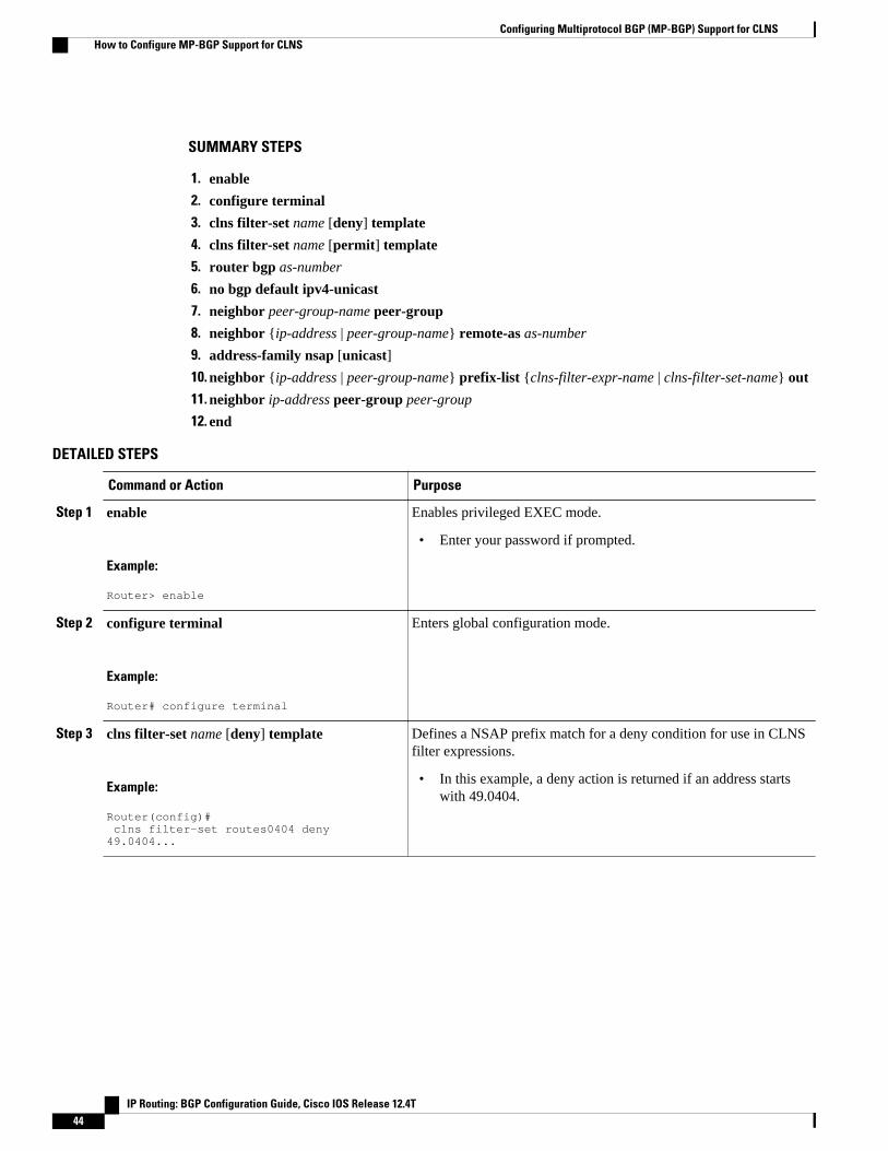
SUMMARY STEPS
1. enable
2. configure terminal
3. clns filter-set name [deny] template
4. clns filter-set name [permit] template
5. router bgp as-number
6. no bgp default ipv4-unicast
7. neighbor peer-group-name peer-group
8. neighbor {ip-address | peer-group-name} remote-as as-number
9. address-family nsap [unicast]
10. neighbor {ip-address | peer-group-name} prefix-list {clns-filter-expr-name | clns-filter-set-name} out
11. neighbor ip-address peer-group peer-group
12. end
DETAILED STEPS
Command or Action Purpose
Step 1 enable
Example:
Router> enable
Enables privileged EXEC mode.
• Enter your password if prompted.
Step 2 configure terminal
Example:
Router# configure terminal
Enters global configuration mode.
Step 3 clns filter-set name [deny] template
Example:
Router(config)# clns filter-set routes0404 deny 49.0404...
Defines a NSAP prefix match for a deny condition for use in CLNSfilter expressions.
• In this example, a deny action is returned if an address startswith 49.0404.
Configuring Multiprotocol BGP (MP-BGP) Support for CLNS How to Configure MP-BGP Support for CLNS
IP Routing: BGP Configuration Guide, Cisco IOS Release 12.4T44

Command or Action Purpose
Step 4 clns filter-set name [permit] template
Example:
Router(config)# clns filter-set routes0404 permit 49...
Defines a NSAP prefix match for a permit condition for use inCLNS filter expressions.
• In this example, a permit action is returned if an address startswith 49.
Note Although the permit example in this step allows all NSAPaddresses starting with 49, the match condition in Step 3 isprocessed first so the NSAP addresses starting with 49.0404are still denied.
Step 5 router bgp as-number
Example:
Router(config)# router bgp 65404
Configures a BGP routing process and enters router configurationmode for the specified routing process.
Step 6 no bgp default ipv4-unicast
Example:
Router(config-router)# no bgp default ipv4-unicast
Disables the default behavior of the BGP routing processexchanging IPv4 addressing information with BGP neighbor routers.
Step 7 neighbor peer-group-name peer-group
Example:
Router(config-router)# neighbor ebgp-peers peer-group
Creates a BGP peer group.
• In this example, the BGP peer group named ebgp-peers iscreated.
Step 8 neighbor {ip-address | peer-group-name}remote-as as-number
Example:
Router(config-router)# neighbor ebgp-peers remote-as 65303
Adds an IP address or peer group name of the BGP neighbor in thespecified autonomous system to the BGP neighbor table of the localrouter.
• In this example, the peer group named ebgp-peers is added tothe BGP neighbor table.
Step 9 address-family nsap [unicast]
Example:
Router(config-router)# address-family nsap
Specifies the NSAP address family and enters address familyconfiguration mode.
Configuring Multiprotocol BGP (MP-BGP) Support for CLNSHow to Configure MP-BGP Support for CLNS
IP Routing: BGP Configuration Guide, Cisco IOS Release 12.4T 45

Command or Action Purpose
Step 10 neighbor {ip-address | peer-group-name} prefix-list {clns-filter-expr-name | clns-filter-set-name}out
Example:
Router(config-router-af)# neighbor ebgp-peers prefix-list routes0404 out
Specifies a CLNS filter set or CLNS filter expression to be used tofilter outbound BGP updates.
• The clns-filter-expr-name argument is defined with the clnsfilter-expr configuration command.
• The clns-filter-set-name argument is defined with the clnsfilter-set configuration command.
• In this example, the filter set named routes0404 was created inStep3 and Step 4.
Step 11 neighbor ip-address peer-group peer-group
Example:
Router(config-router-af)# neighbor 10.6.7.8 peer-group ebgp-peers
Assigns a BGP neighbor to a BGP peer group.
Step 12 end
Example:
Router(config-router-af)# end
Exits address family configuration mode and returns to privilegedEXEC mode.
Originating Default Routes for a Neighboring Routing DomainTo create a default CLNS route that points to the local router on behalf of a neighboring OSI routingdomain, perform the steps in this procedure. This is an optional task and is normally used only withexternal BGP neighbors.
SUMMARY STEPS
1. enable
2. configure terminal
3. router bgp as-number
4. no bgp default ipv4-unicast
5. address-family nsap [unicast]
6. neighbor {ip-address | peer-group-name} default-originate [route-map map-tag]
7. end
Originating Default Routes for a Neighboring Routing Domain How to Configure MP-BGP Support for CLNS
IP Routing: BGP Configuration Guide, Cisco IOS Release 12.4T46
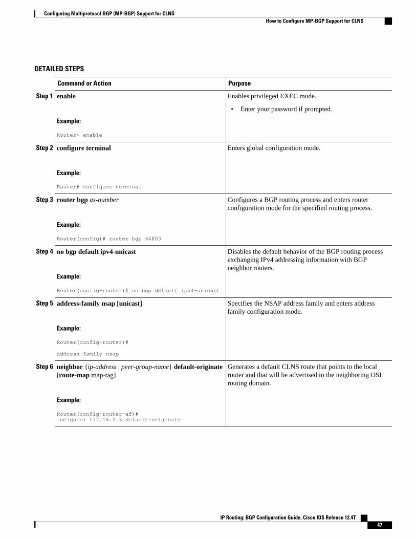
DETAILED STEPS
Command or Action Purpose
Step 1 enable
Example:
Router> enable
Enables privileged EXEC mode.
• Enter your password if prompted.
Step 2 configure terminal
Example:
Router# configure terminal
Enters global configuration mode.
Step 3 router bgp as-number
Example:
Router(config)# router bgp 64803
Configures a BGP routing process and enters routerconfiguration mode for the specified routing process.
Step 4 no bgp default ipv4-unicast
Example:
Router(config-router)# no bgp default ipv4-unicast
Disables the default behavior of the BGP routing processexchanging IPv4 addressing information with BGPneighbor routers.
Step 5 address-family nsap [unicast]
Example:
Router(config-router)# address-family nsap
Specifies the NSAP address family and enters addressfamily configuration mode.
Step 6 neighbor {ip-address | peer-group-name} default-originate[route-map map-tag]
Example:
Router(config-router-af)# neighbor 172.16.2.3 default-originate
Generates a default CLNS route that points to the localrouter and that will be advertised to the neighboring OSIrouting domain.
Configuring Multiprotocol BGP (MP-BGP) Support for CLNSHow to Configure MP-BGP Support for CLNS
IP Routing: BGP Configuration Guide, Cisco IOS Release 12.4T 47

Command or Action Purpose
Step 7 end
Example:
Router(config-router-af)# end
Exits address family configuration mode and returns toprivileged EXEC mode.
Verifying MP-BGP Support for CLNSTo verify the configuration, use the show running-config EXEC command. Sample output is located in the Implementing MP-BGP Support for CLNS Example, page 55. To verify that the Multiprotocol BGP(MP-BGP) Support for CLNS feature is working, perform the following steps.
SUMMARY STEPS
1. show clns neighbors
2. show clns route
3. show bgp nsap unicast summary
4. Enter the show bgp nsap unicast command to display all the NSAP prefix routes that the local routerhas discovered. In the following example of output from router R2, shown in the figure above (in the"Generic BGP CLNS Network Topology" section), a single valid route to prefix 49.0101 is shown. Twovalid routes--marked by a *--are shown for the prefix 49.0404. The second route is marked with a *>isequence, representing the best route to this prefix.
DETAILED STEPS
Step 1 show clns neighborsUse this command to confirm that the local router has formed all the necessary IS-IS adjacencies with other Level 2IS-IS routers in the local OSI routing domain. If the local router has any directly connected external BGP peers, theoutput from this command will show that the external neighbors have been discovered, in the form of ES-ISadjacencies.
In the following example, the output is displayed for router R2, shown in the figure above (in the "Generic BGPCLNS Network Topology" section). R2 has three CLNS neighbors. R1 and R4 are ES-IS neighbors because thesenodes are in different autonomous systems from R2. R3 is an IS-IS neighbor because it is in the same autonomoussystem as R2. Note that the system ID is replaced by CLNS hostnames (r1, r3, and r4) that are defined at the start ofeach configuration file. Specifying the CLNS hostname means that you need not remember which system IDcorresponds to which hostname.
Example:
Router# show clns neighborsTag osi-as-202:System Id Interface SNPA State Holdtime Type Protocolr1 Se2/0 *HDLC* Up 274 IS ES-IS
Verifying MP-BGP Support for CLNS How to Configure MP-BGP Support for CLNS
IP Routing: BGP Configuration Guide, Cisco IOS Release 12.4T48

r3 Et0/1 0002.16de.8481 Up 9 L2 IS-ISr4 Se2/2 *HDLC* Up 275 IS ES-IS
Step 2 show clns routeUse this command to confirm that the local router has calculated routes to other areas in the local OSI routing domain.In the following example of output from router R2, shown in the figure above (in the "Generic BGP CLNS NetworkTopology" section), the routing table entry--i 49.0202.3333 [110/10] via R3--shows that router R2 knows about otherlocal IS-IS areas within the local OSI routing domain.
Example:
Router# show clns routeCodes: C - connected, S - static, d - DecnetIV I - ISO-IGRP, i - IS-IS, e - ES-IS B - BGP, b - eBGP-neighborC 49.0202.2222 [2/0], Local IS-IS AreaC 49.0202.2222.2222.2222.2222.00 [1/0], Local IS-IS NETb 49.0101.1111.1111.1111.1111.00 [15/10] via r1, Serial2/0i 49.0202.3333 [110/10] via r3, Ethernet0/1b 49.0303.4444.4444.4444.4444.00 [15/10] via r4, Serial2/2B 49.0101 [20/1] via r1, Serial2/0B 49.0303 [20/1] via r4, Serial2/2B 49.0404 [200/1] via r9i 49.0404.9999.9999.9999.9999.00 [110/10] via r3, Ethernet0/1
Step 3 show bgp nsap unicast summaryUse this command to verify that the TCP connection to a particular neighbor is active. In the following exampleoutput, search the appropriate row based on the IP address of the neighbor. If the State/PfxRcd column entry is anumber, including zero, the TCP connection for that neighbor is active.
Example:
Router# show bgp nsap unicast summaryBGP router identifier 10.1.57.11, local AS number 65202BGP table version is 6, main routing table version 65 network entries and 8 paths using 1141 bytes of memory6 BGP path attribute entries using 360 bytes of memory4 BGP AS-PATH entries using 96 bytes of memory0 BGP route-map cache entries using 0 bytes of memory0 BGP filter-list cache entries using 0 bytes of memoryBGP activity 5/0 prefixes, 8/0 paths, scan interval 60 secsNeighbor V AS MsgRcvd MsgSent TblVer InQ OutQ Up/Down State/PfxRcd10.1.2.1 4 65101 34 34 6 0 0 00:29:11 110.2.3.3 4 65202 35 36 6 0 0 00:29:16 3
Step 4 Enter the show bgp nsap unicast command to display all the NSAP prefix routes that the local router has discovered.In the following example of output from router R2, shown in the figure above (in the "Generic BGP CLNS NetworkTopology" section), a single valid route to prefix 49.0101 is shown. Two valid routes--marked by a *--are shown forthe prefix 49.0404. The second route is marked with a *>i sequence, representing the best route to this prefix.
Example:
Router# show bgp nsap unicastBGP table version is 3, local router ID is 192.168.3.1Status codes: s suppressed, d damped, h history, * valid, > best, i - internal,
Configuring Multiprotocol BGP (MP-BGP) Support for CLNSHow to Configure MP-BGP Support for CLNS
IP Routing: BGP Configuration Guide, Cisco IOS Release 12.4T 49

r RIB-failure, S StaleOrigin codes: i - IGP, e - EGP, ? - incomplete Network Next Hop Metric LocPrf Weight Path*> 49.0101 49.0101.1111.1111.1111.1111.00 0 65101 i* i49.0202.2222 49.0202.3333.3333.3333.3333.00 100 0 ?*> 49.0202.2222.2222.2222.2222.00 32768 ?* i49.0202.3333 49.0202.3333.3333.3333.3333.00 100 0 ?*> 49.0202.2222.2222.2222.2222.00 32768 ?*> 49.0303 49.0303.4444.4444.4444.4444.00 0 65303 i* 49.0404 49.0303.4444.4444.4444.4444.00 0 65303 65404 i*>i 49.0404.9999.9999.9999.9999.00 100 0 65404 i
Troubleshooting MP-BGP Support for CLNSThe debug bgp nsap unicastcommands enable diagnostic output concerning various events relating to theoperation of the CLNS packets in the BGP routing protocol to be displayed on a console. These commandsare intended only for troubleshooting purposes because the volume of output generated by the softwarewhen they are used can result in severe performance degradation on the router. See the Cisco IOS DebugCommand Reference for more information about using these debug commands.
To troubleshoot problems with the configuration of MP-BGP support for CLNS and to minimize the impactof the debugcommands used in this procedure, perform the following steps.
SUMMARY STEPS
1. Attach a console directly to a router running the Cisco IOS software release that includes theMultiprotocol BGP (MP-BGP) Support for CLNS feature.
2. no logging console
3. Use Telnet to access a router port.
4. enable
5. terminal monitor
6. debug bgp nsap unicast [neighbor-address | dampening | keepalives | updates]
7. no terminal monitor
8. no debug bgp nsap unicast [neighbor-address | dampening | keepalives | updates]
9. logging console
DETAILED STEPS
Step 1 Attach a console directly to a router running the Cisco IOS software release that includes the Multiprotocol BGP (MP-BGP) Support for CLNS feature.
Troubleshooting MP-BGP Support for CLNS How to Configure MP-BGP Support for CLNS
IP Routing: BGP Configuration Guide, Cisco IOS Release 12.4T50

Note This procedure will minimize the load on the router created by the debug bgp nsap unicast commands becausethe console port will no longer be generating character-by-character processor interrupts. If you cannot connectto a console directly, you can run this procedure via a terminal server. If you must break the Telnet connection,however, you may not be able to reconnect because the router may be unable to respond due to the processorload of generating the debug bgp nsap unicast output.
Step 2 no logging consoleThis command disables all logging to the console terminal.
Step 3 Use Telnet to access a router port.
Step 4 enableEnter this command to access privileged EXEC mode.
Step 5 terminal monitorThis command enables logging on the virtual terminal.
Step 6 debug bgp nsap unicast [neighbor-address | dampening | keepalives | updates]Enter only specific debug bgp nsap unicastcommands to isolate the output to a certain subcomponent and minimizethe load on the processor. Use appropriate arguments and keywords to generate more detailed debug information onspecified subcomponents.
Step 7 no terminal monitorThis command disables logging on the virtual terminal.
Step 8 no debug bgp nsap unicast [neighbor-address | dampening | keepalives | updates]Enter the specific no debug bgp nsap unicastcommand when you are finished.
Step 9 logging consoleThis command reenables logging to the console.
Configuration Examples for MP-BGP Support for CLNSThis section provides configuration examples to match the identified configuration tasks in the previoussection. To provide an overview of all the router configurations in the figure above (in the "Generic BGPCLNS Network Topology" section), more detailed configurations for each router are added at the end ofthis section.
• Configuring and Activating a BGP Neighbor to Support CLNS Example, page 52
• Configuring an IS-IS Routing Process Example, page 52
• Configuring Interfaces Example, page 52
• Advertising Networking Prefixes Example, page 52
• Redistributing Routes from BGP into IS-IS Example, page 53
• Redistributing Routes from IS-IS into BGP Example, page 53
• Configuring BGP Peer Groups and Route Reflectors Example, page 53
• Filtering Inbound Routes Based on NSAP Prefixes Example, page 54
• Filtering Outbound BGP Updates Based on NSAP Prefixes Example, page 54
• Originating a Default Route and Outbound Route Filtering Example, page 54
• Implementing MP-BGP Support for CLNS Example, page 55
Configuring Multiprotocol BGP (MP-BGP) Support for CLNSConfiguration Examples for MP-BGP Support for CLNS
IP Routing: BGP Configuration Guide, Cisco IOS Release 12.4T 51

Configuring and Activating a BGP Neighbor to Support CLNS ExampleIn the following example, the router R1, shown in the figure below, in the autonomous system AS65101 isconfigured to run BGP and activated to support CLNS. Router R1 is the only Level 2 IS-IS router inautonomous system AS65101, and it has only one connection to another autonomous system via router R2in AS65202. The no bgp default ipv4-unicast command is configured on the router to disable the defaultbehavior of the BGP routing process exchanging IPv4 addressing information with BGP neighbor routers.After the NSAP address family configuration mode is enabled with the address-family nsap command, therouter is configured to advertise the NSAP prefix of 49.0101 to its BGP neighbors and to send NSAProuting information to the BGP neighbor at 10.1.2.2.
router bgp 65101 no bgp default ipv4-unicast address-family nsap network 49.0101... neighbor 10.1.2.2 activate exit-address-family
Configuring an IS-IS Routing Process ExampleIn the following example, the router R1, shown in he figure below, is configured to run an IS-IS process:
router isis osi-as-101 net 49.0101.1111.1111.1111.1111.00
The default IS-IS routing process level is used.
Configuring Interfaces ExampleIn the following example, two of the interfaces of the router R2, shown in the figure below, in theautonomous system AS65202 are configured to run CLNS. Ethernet interface 0/1 is connected to the localOSI routing domain and is configured to run IS-IS when the network protocol is CLNS using the clnsrouter isis command. The serial interface 2/0 with the local IP address of 10.1.2.2 is connected with aneBGP neighbor and is configured to run CLNS through the clns enable command:
interface serial 2/0 ip address 10.1.2.2 255.255.255.0 clns enable no shutdown!interface ethernet 0/1 ip address 10.2.3.1 255.255.255.0 clns router isis osi-as-202 no shutdown
Advertising Networking Prefixes ExampleIn the following example, the router R1, shown in the figure below, is configured to advertise the NSAPprefix of 49.0101 to other routers. The NSAP prefix unique to autonomous system AS65101 is advertisedto allow the other autonomous systems to discover the existence of autonomous system AS65101 in thenetwork:
router bgp 65101 no bgp default ipv4-unicast neighbor 10.1.2.2 remote-as 64202 address-family nsap
Configuring and Activating a BGP Neighbor to Support CLNS Example Configuration Examples for MP-BGP Support for CLNS
IP Routing: BGP Configuration Guide, Cisco IOS Release 12.4T52

network 49.0101... neighbor 10.1.2.2 activate
Redistributing Routes from BGP into IS-IS ExampleIn the following example, the routers R7 and R9, shown in the figure below, in the autonomous systemAS65404 are configured to redistribute BGP routes into the IS-IS routing process called osi-as-404.Redistributing the BGP routes allows the Level 2 IS-IS router, R8, to advertise routes to destinationsoutside the autonomous system AS65404. Without a route map being specified, all BGP routes areredistributed.
Router R7
router isis osi-as-404 net 49.0404.7777.7777.7777.7777.00 redistribute bgp 65404 clns
Router R9
router isis osi-as-404 net 49.0404.9999.9999.9999.9999.00 redistribute bgp 65404 clns
Redistributing Routes from IS-IS into BGP ExampleIn the following example, the router R2, shown in the figure below, in the autonomous system AS65202 isconfigured to redistribute Level 2 CLNS NSAP routes into BGP. A route map is used to permit only routesfrom within the local autonomous system to be redistributed into BGP. Without a route map beingspecified, every NSAP route from the CLNS level 2 prefix table is redistributed. The no bgp default ipv4-unicast command is configured on the router to disable the default behavior of the BGP routing processexchanging IPv4 addressing information with BGP neighbor routers.
clns filter-set internal-routes permit 49.0202...!route-map internal-routes-only permit 10 match clns address internal-routes!router isis osi-as-202 net 49.0202.2222.2222.2222.2222.00!router bgp 65202 no bgp default ipv4-unicast address-family nsap redistribute isis osi-as-202 clns route-map internal-routes-only
Configuring BGP Peer Groups and Route Reflectors ExampleRouter R5, shown in the figure above (in the "Generic BGP CLNS Network Topology" section), has onlyiBGP neighbors and runs IS-IS on both interfaces. To reduce the number of configuration commands,configure R5 as a member of a BGP peer group called ibgp-peers. The peer group is automaticallyactivated under the address-family nsap command by configuring the peer group as a route reflector clientallowing it to exchange NSAP routing information between group members. The BGP peer group is alsoconfigured as a BGP route reflector client to reduce the need for every iBGP router to be linked to eachother.
Redistributing Routes from BGP into IS-IS ExampleConfiguration Examples for MP-BGP Support for CLNS
IP Routing: BGP Configuration Guide, Cisco IOS Release 12.4T 53

In the following example, the router R5 in the autonomous system AS65303 is configured as a member of aBGP peer group and a BGP route reflector client.
router bgp 65303 no bgp default ipv4-unicast neighbor ibgp-peers peer-group neighbor ibgp-peers remote-as 65303 address-family nsap neighbor ibgp-peers route-reflector-client neighbor 10.4.5.4 peer-group ibgp-peers neighbor 10.5.6.6 peer-group ibgp-peers exit-address-family
Filtering Inbound Routes Based on NSAP Prefixes ExampleIn the following example, the router R1, shown in the figure below, in the autonomous system AS65101 isconfigured to filter inbound routes specified by the default-prefix-only prefix list.
clns filter-set default-prefix-only deny 49...clns filter-set default-prefix-only permit default!router isis osi-as-101 net 49.0101.1111.1111.1111.1111.00!router bgp 65101 no bgp default ipv4-unicast neighbor 10.1.2.2 remote-as 64202 address-family nsap network 49.0101.1111.1111.1111.1111.00 neighbor 10.1.2.2 activate neighbor 10.1.2.2 prefix-list default-prefix-only in
Filtering Outbound BGP Updates Based on NSAP Prefixes ExampleIn the following example, outbound BGP updates are filtered based on NSAP prefixes. This example isconfigured at Router 7 in the figure below. In this task, a CLNS filter is created with two entries to denyNSAP prefixes starting with 49.0404 and to permit all other NSAP prefixes starting with 49. A BGP peergroup is created and the filter is applied to outbound BGP updates for the neighbor that is a member of thepeer group.
clns filter-set routes0404 deny 49.0404...clns filter-set routes0404 permit 49...!router bgp 65404 no bgp default ipv4-unicast neighbor ebgp-peers remote-as 65303 address-family nsap neighbor ebgp-peers prefix-list routes0404 out neighbor 10.6.7.8 peer-group ebgp-peers
Originating a Default Route and Outbound Route Filtering ExampleIn the figure below, autonomous system AS65101 is connected to only one other autonomous system,AS65202. Router R2 in AS65202 provides the connectivity to the rest of the network for autonomoussystem AS65101 by sending a default route to R1. Any packets from Level 1 routers within autonomoussystem AS65101 with destination NSAP addresses outside the local Level 1 network are sent to R1, thenearest Level 2 router. Router R1 forwards the packets to router R2 using the default route.
In the following example, the router R2, shown in the figure below, in the autonomous system AS65202 isconfigured to generate a default route for router R1 in the autonomous system AS65101, and an outbound
Filtering Inbound Routes Based on NSAP Prefixes Example Configuration Examples for MP-BGP Support for CLNS
IP Routing: BGP Configuration Guide, Cisco IOS Release 12.4T54

filter is created to send only the default route NSAP addressing information in the BGP update messages torouter R1.
clns filter-set default-prefix-only deny 49...clns filter-set default-prefix-only permit default!router bgp 65202 no bgp default ipv4-unicast neighbor 10.1.2.1 remote-as 64101 address-family nsap network 49.0202... neighbor 10.1.2.1 activate neighbor 10.1.2.1 default-originate neighbor 10.1.2.1 prefix-list default-prefix-only out
Implementing MP-BGP Support for CLNS ExampleThe figure below shows a generic BGP CLNS network containing nine routers that are grouped into fourdifferent autonomous systems (in BGP terminology) or routing domains (in OSI terminology). This sectioncontains complete configurations for all routers shown in the figure below.
Figure 7 Components in a Generic BGP CLNS Network
If you need more details about commands used in the following examples, see the configuration tasksearlier in this document and the documents listed in the Additional References, page 60.
• Autonomous System AS65101, page 56
• Autonomous System AS65202, page 56
• Autonomous System AS65303, page 57
• Autonomous System AS65404, page 58
Implementing MP-BGP Support for CLNS ExampleConfiguration Examples for MP-BGP Support for CLNS
IP Routing: BGP Configuration Guide, Cisco IOS Release 12.4T 55
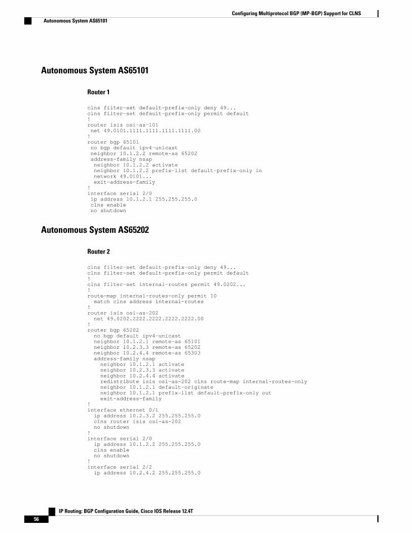
Autonomous System AS65101
Router 1
clns filter-set default-prefix-only deny 49...clns filter-set default-prefix-only permit default!router isis osi-as-101 net 49.0101.1111.1111.1111.1111.00!router bgp 65101 no bgp default ipv4-unicast neighbor 10.1.2.2 remote-as 65202 address-family nsap neighbor 10.1.2.2 activate neighbor 10.1.2.2 prefix-list default-prefix-only in network 49.0101... exit-address-family!interface serial 2/0 ip address 10.1.2.1 255.255.255.0 clns enable no shutdown
Autonomous System AS65202
Router 2
clns filter-set default-prefix-only deny 49...clns filter-set default-prefix-only permit default!clns filter-set internal-routes permit 49.0202...!route-map internal-routes-only permit 10 match clns address internal-routes!router isis osi-as-202 net 49.0202.2222.2222.2222.2222.00!router bgp 65202 no bgp default ipv4-unicast neighbor 10.1.2.1 remote-as 65101 neighbor 10.2.3.3 remote-as 65202 neighbor 10.2.4.4 remote-as 65303 address-family nsap neighbor 10.1.2.1 activate neighbor 10.2.3.3 activate neighbor 10.2.4.4 activate redistribute isis osi-as-202 clns route-map internal-routes-only neighbor 10.1.2.1 default-originate neighbor 10.1.2.1 prefix-list default-prefix-only out exit-address-family!interface ethernet 0/1 ip address 10.2.3.2 255.255.255.0 clns router isis osi-as-202 no shutdown!interface serial 2/0 ip address 10.1.2.2 255.255.255.0 clns enable no shutdown!interface serial 2/2 ip address 10.2.4.2 255.255.255.0
Configuring Multiprotocol BGP (MP-BGP) Support for CLNS Autonomous System AS65101
IP Routing: BGP Configuration Guide, Cisco IOS Release 12.4T56

clns enable no shutdown
Router 3
clns filter-set internal-routes permit 49.0202...!route-map internal-routes-only permit 10 match clns address internal-routes!router isis osi-as-202 net 49.0202.3333.3333.3333.3333.00!router bgp 65202 no bgp default ipv4-unicast neighbor 10.2.3.2 remote-as 65202 neighbor 10.3.9.9 remote-as 65404 address-family nsap neighbor 10.2.3.2 activate neighbor 10.3.9.9 activate redistribute isis osi-as-202 clns route-map internal-routes-only exit-address-family!interface ethernet 0/1 ip address 10.2.3.3 255.255.255.0 clns router isis osi-as-202 no shutdown!interface serial 2/2 ip address 10.3.9.3 255.255.255.0 clns enable no shutdown
Autonomous System AS65303
Router 4
router isis osi-as-303 net 49.0303.4444.4444.4444.4444.00!router bgp 65303 no bgp default ipv4-unicast neighbor 10.2.4.2 remote-as 65202 neighbor 10.4.5.5 remote-as 65303 address-family nsap no synchronization neighbor 10.2.4.2 activate neighbor 10.4.5.5 activate network 49.0303... exit-address-family!interface ethernet 0/2 ip address 10.4.5.4 255.255.255.0 clns router isis osi-as-303 no shutdown!interface serial 2/3 ip address 10.2.4.4 255.255.255.0 clns enable no shutdown
Router 5
router isis osi-as-303 net 49.0303.5555.5555.5555.5555.00!
Configuring Multiprotocol BGP (MP-BGP) Support for CLNSAutonomous System AS65303
IP Routing: BGP Configuration Guide, Cisco IOS Release 12.4T 57
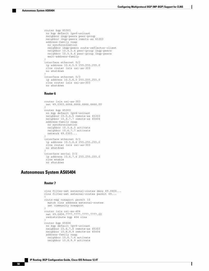
router bgp 65303 no bgp default ipv4-unicast neighbor ibgp-peers peer-group neighbor ibgp-peers remote-as 65303 address-family nsap no synchronization neighbor ibgp-peers route-reflector-client neighbor 10.4.5.4 peer-group ibgp-peers neighbor 10.5.6.6 peer-group ibgp-peers exit-address-family!interface ethernet 0/2 ip address 10.4.5.5 255.255.255.0 clns router isis osi-as-303 no shutdown!interface ethernet 0/3 ip address 10.5.6.5 255.255.255.0 clns router isis osi-as-303 no shutdown
Router 6
router isis osi-as-303 net 49.0303.6666.6666.6666.6666.00!router bgp 65303 no bgp default ipv4-unicast neighbor 10.5.6.5 remote-as 65303 neighbor 10.6.7.7 remote-as 65404 address-family nsap no synchronization neighbor 10.5.6.5 activate neighbor 10.6.7.7 activate network 49.0303...!interface ethernet 0/3 ip address 10.5.6.6 255.255.255.0 clns router isis osi-as-303 no shutdown!interface serial 2/2 ip address 10.6.7.6 255.255.255.0 clns enable no shutdown
Autonomous System AS65404
Router 7
clns filter-set external-routes deny 49.0404...clns filter-set external-routes permit 49...!route-map noexport permit 10 match clns address external-routes set community noexport!router isis osi-as-404 net 49.0404.7777.7777.7777.7777.00 redistribute bgp 404 clns!router bgp 65404 no bgp default ipv4-unicast neighbor 10.6.7.6 remote-as 65303 neighbor 10.8.9.9 remote-as 65404 address-family nsap neighbor 10.6.7.6 activate neighbor 10.8.9.9 activate
Configuring Multiprotocol BGP (MP-BGP) Support for CLNS Autonomous System AS65404
IP Routing: BGP Configuration Guide, Cisco IOS Release 12.4T58
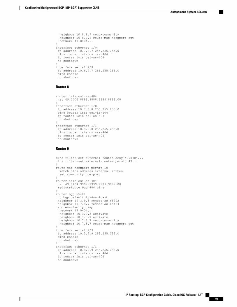
neighbor 10.8.9.9 send-community neighbor 10.8.9.9 route-map noexport out network 49.0404...!interface ethernet 1/0 ip address 10.7.8.7 255.255.255.0 clns router isis osi-as-404 ip router isis osi-as-404 no shutdown!interface serial 2/3 ip address 10.6.7.7 255.255.255.0 clns enable no shutdown
Router 8
router isis osi-as-404 net 49.0404.8888.8888.8888.8888.00!interface ethernet 1/0 ip address 10.7.8.8 255.255.255.0 clns router isis osi-as-404 ip router isis osi-as-404 no shutdown!interface ethernet 1/1 ip address 10.8.9.8 255.255.255.0 clns router isis osi-as-404 ip router isis osi-as-404 no shutdown
Router 9
clns filter-set external-routes deny 49.0404...clns filter-set external-routes permit 49...!route-map noexport permit 10 match clns address external-routes set community noexport!router isis osi-as-404 net 49.0404.9999.9999.9999.9999.00 redistribute bgp 404 clns!router bgp 65404 no bgp default ipv4-unicast neighbor 10.3.9.3 remote-as 65202 neighbor 10.7.8.7 remote-as 65404 address-family nsap network 49.0404... neighbor 10.3.9.3 activate neighbor 10.7.8.7 activate neighbor 10.7.8.7 send-community neighbor 10.7.8.7 route-map noexport out!interface serial 2/3 ip address 10.3.9.9 255.255.255.0 clns enable no shutdown!interface ethernet 1/1 ip address 10.8.9.9 255.255.255.0 clns router isis osi-as-404 ip router isis osi-as-404 no shutdown
Configuring Multiprotocol BGP (MP-BGP) Support for CLNSAutonomous System AS65404
IP Routing: BGP Configuration Guide, Cisco IOS Release 12.4T 59

Additional ReferencesThe following sections provide references related to the Multiprotocol BGP (MP-BGP) Support for CLNSfeature.
Related Documents
Related Topic Document Title
BGP commands Cisco IOS IP Routing: BGP Command Reference
CLNS commands Cisco IOS ISO CLNS Command Reference
Standards
Standard Title
ISO/IEC 8473 ISO CLNP: Connectionless Network Protocol (ISO-IP). Protocol for providing the connectionless-modenetwork service.
ISO/IEC 9542 End System to Intermediate System Protocol(ESIS). End system to Intermediate system routingexchange protocol for use in conjunction with theprotocol for providing the connectionless-modenetwork service (ISO 8473).
ISO/IEC 10589 IS-IS, Intermediate System-to-Intermediate System.Intermediate system to Intermediate systemintradomain routing information exchange protocolfor use in conjunction with the protocol forproviding the connectionless-mode network service(ISO 8473).
MIBs
MIB MIBs Link
None. To locate and download MIBs for selectedplatforms, Cisco IOS releases, and feature sets, useCisco MIB Locator found at the following URL:
http://www.cisco.com/go/mibs
RFCs
RFC Title
RFC 1700 Assigned Numbers
RFC 1771 A Border Gateway Protocol 4 (BGP-4)
Configuring Multiprotocol BGP (MP-BGP) Support for CLNS Additional References
IP Routing: BGP Configuration Guide, Cisco IOS Release 12.4T60

RFC Title
RFC 1997 BGP Communities Attribute
RFC 2042 Registering New BGP Attribute Types
RFC 2439 BGP Route Flap Dampening
RFC 2842 Capabilities Advertisement with BGP-4
RFC 2858 Multiprotocol Extensions for BGP-4
RFC 2918 Route Refresh Capability for BGP-4
Technical Assistance
Description Link
The Cisco Support website provides extensiveonline resources, including documentation and toolsfor troubleshooting and resolving technical issueswith Cisco products and technologies. Access tomost tools on the Cisco Support website requires aCisco.com user ID and password. If you have avalid service contract but do not have a user ID orpassword, you can register on Cisco.com.
http://www.cisco.com/techsupport
Feature Information for Configuring MP-BGP Support forCLNS
The following table provides release information about the feature or features described in this module.This table lists only the software release that introduced support for a given feature in a given softwarerelease train. Unless noted otherwise, subsequent releases of that software release train also support thatfeature.
Use Cisco Feature Navigator to find information about platform support and Cisco software image support.To access Cisco Feature Navigator, go to www.cisco.com/go/cfn. An account on Cisco.com is not required.
Configuring Multiprotocol BGP (MP-BGP) Support for CLNSFeature Information for Configuring MP-BGP Support for CLNS
IP Routing: BGP Configuration Guide, Cisco IOS Release 12.4T 61

Table 6 Feature Information for MP-BGP Support for CLNS
Feature Name Releases Feature Information
Multiprotocol BGP (MP-BGP)Support for CLNS
12.2(8)T 12.2(33)SRB The Multiprotocol BGP (MP-BGP) Support for CLNS featureprovides the ability to scaleConnectionless Network Service(CLNS) networks. Themultiprotocol extensions ofBorder Gateway Protocol (BGP)add the ability to interconnectseparate Open SystemInterconnection (OSI) routingdomains without merging therouting domains, thus providingthe capability to build very largeOSI networks.
In Release 12.2(8)T, this featurewas introduced on the followingplatforms:
• Cisco 2600 series• Cisco 3600 series• Cisco 7100 series• Cisco 7200 series• Cisco 7500 series• Cisco uBR7200 series
In Release 12.2(33)SRB, thisfeature was introduced on theCisco 7600 Series.
The following commands wereintroduced or modified by thisfeature: address-family nsap,clear bgp nsap, clear bgp nsapdampening, clear bgp nsapexternal, clear bgp nsap flap-statistics, clear bgp nsap peer-group, debug bgp nsap, debugbgp nsap dampening, debugbgp nsap updates, neighborprefix-list, network (BGP andmultiprotocol BGP),redistribute (BGP to ISO ISIS),redistribute (ISO ISIS to BGP),show bgp nsap, show bgp nsapcommunity, show bgp nsapcommunity-list, show bgp nsapdampened-paths, show bgpnsap filter-list, show bgp nsap
Configuring Multiprotocol BGP (MP-BGP) Support for CLNS Feature Information for Configuring MP-BGP Support for CLNS
IP Routing: BGP Configuration Guide, Cisco IOS Release 12.4T62
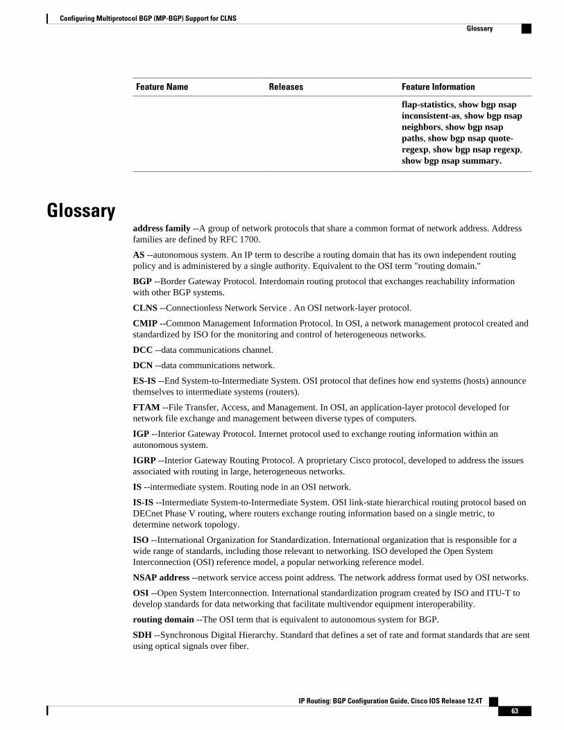
Feature Name Releases Feature Information
flap-statistics, show bgp nsapinconsistent-as, show bgp nsapneighbors, show bgp nsappaths, show bgp nsap quote-regexp, show bgp nsap regexp,show bgp nsap summary.
Glossaryaddress family --A group of network protocols that share a common format of network address. Addressfamilies are defined by RFC 1700.
AS --autonomous system. An IP term to describe a routing domain that has its own independent routingpolicy and is administered by a single authority. Equivalent to the OSI term "routing domain."
BGP --Border Gateway Protocol. Interdomain routing protocol that exchanges reachability informationwith other BGP systems.
CLNS --Connectionless Network Service . An OSI network-layer protocol.
CMIP --Common Management Information Protocol. In OSI, a network management protocol created andstandardized by ISO for the monitoring and control of heterogeneous networks.
DCC --data communications channel.
DCN --data communications network.
ES-IS --End System-to-Intermediate System. OSI protocol that defines how end systems (hosts) announcethemselves to intermediate systems (routers).
FTAM --File Transfer, Access, and Management. In OSI, an application-layer protocol developed fornetwork file exchange and management between diverse types of computers.
IGP --Interior Gateway Protocol. Internet protocol used to exchange routing information within anautonomous system.
IGRP --Interior Gateway Routing Protocol. A proprietary Cisco protocol, developed to address the issuesassociated with routing in large, heterogeneous networks.
IS --intermediate system. Routing node in an OSI network.
IS-IS --Intermediate System-to-Intermediate System. OSI link-state hierarchical routing protocol based onDECnet Phase V routing, where routers exchange routing information based on a single metric, todetermine network topology.
ISO --International Organization for Standardization. International organization that is responsible for awide range of standards, including those relevant to networking. ISO developed the Open SystemInterconnection (OSI) reference model, a popular networking reference model.
NSAP address --network service access point address. The network address format used by OSI networks.
OSI --Open System Interconnection. International standardization program created by ISO and ITU-T todevelop standards for data networking that facilitate multivendor equipment interoperability.
routing domain --The OSI term that is equivalent to autonomous system for BGP.
SDH --Synchronous Digital Hierarchy. Standard that defines a set of rate and format standards that are sentusing optical signals over fiber.
Configuring Multiprotocol BGP (MP-BGP) Support for CLNSGlossary
IP Routing: BGP Configuration Guide, Cisco IOS Release 12.4T 63
SONET --Synchronous Optical Network. High-speed synchronous network specification designed to runon optical fiber.
Cisco and the Cisco logo are trademarks or registered trademarks of Cisco and/or its affiliates in the U.S.and other countries. To view a list of Cisco trademarks, go to this URL: www.cisco.com/go/trademarks.Third-party trademarks mentioned are the property of their respective owners. The use of the word partnerdoes not imply a partnership relationship between Cisco and any other company. (1110R)
Any Internet Protocol (IP) addresses and phone numbers used in this document are not intended to beactual addresses and phone numbers. Any examples, command display output, network topology diagrams,and other figures included in the document are shown for illustrative purposes only. Any use of actual IPaddresses or phone numbers in illustrative content is unintentional and coincidental.
Configuring Multiprotocol BGP (MP-BGP) Support for CLNS
IP Routing: BGP Configuration Guide, Cisco IOS Release 12.4T64

Configuring a Basic BGP Network
This module describes the basic tasks to configure a basic Border Gateway Protocol (BGP) network. BGPis an interdomain routing protocol that is designed to provide loop-free routing between organizations.The Cisco IOS implementation of the neighbor and address family commands is explained. This modulealso contains tasks to configure and customize BGP peers, implement BGP route aggregation, configureBGP route origination, and define BGP backdoor routes. BGP peer group definition is documented, peersession templates are introduced, and update groups are explained,
• Finding Feature Information, page 65• Prerequisites for Configuring a Basic BGP Network, page 65• Restrictions for Configuring a Basic BGP Network, page 65• Information About Configuring a Basic BGP Network, page 66• How to Configure a Basic BGP Network, page 81• Configuration Examples for a Basic BGP Network, page 147• Where to Go Next, page 160• Additional References, page 160• Feature Information for Configuring a Basic BGP Network, page 162
Finding Feature InformationYour software release may not support all the features documented in this module. For the latest featureinformation and caveats, see the release notes for your platform and software release. To find informationabout the features documented in this module, and to see a list of the releases in which each feature issupported, see the Feature Information Table at the end of this document.
Use Cisco Feature Navigator to find information about platform support and Cisco software image support.To access Cisco Feature Navigator, go to www.cisco.com/go/cfn. An account on Cisco.com is not required.
Prerequisites for Configuring a Basic BGP NetworkBefore configuring a basic BGP network, you should be familiar with the "Cisco BGP Overview" module.
Restrictions for Configuring a Basic BGP NetworkA router that runs Cisco IOS software can be configured to run only one BGP routing process and to be amember of only one BGP autonomous system. However, a BGP routing process and autonomous systemcan support multiple address family configurations.
IP Routing: BGP Configuration Guide, Cisco IOS Release 12.4T 65

Information About Configuring a Basic BGP Network• BGP Version 4, page 66
• BGP Router ID, page 67
• BGP-Speaker and Peer Relationships, page 67
• BGP Autonomous System Number Formats, page 67
• Cisco Implementation of 4-Byte Autonomous System Numbers, page 70
• BGP Peer Session Establishment, page 70
• Cisco Implementation of BGP Global and Address Family Configuration Commands, page 71
• BGP Session Reset, page 73
• BGP Route Aggregation, page 73
• BGP Aggregation Route AS-SET Information Generation, page 73
• Routing Policy Change Management, page 74
• Conditional BGP Route Injection, page 75
• BGP Peer Groups, page 76
• BGP Backdoor Routes, page 76
• Peer Groups and BGP Update Messages, page 77
• BGP Update Group, page 77
• BGP Dynamic Update Group Configuration, page 77
• BGP Peer Templates, page 77
• Inheritance in Peer Templates, page 78
• Peer Session Templates, page 79
• Peer Policy Templates, page 80
• BGP IPv6 Neighbor Activation Under the IPv4 Address Family, page 81
BGP Version 4Border Gateway Protocol (BGP) is an interdomain routing protocol designed to provide loop-free routingbetween separate routing domains that contain independent routing policies (autonomous systems). TheCisco IOSsoftware implementation of BGP version 4 includes multiprotocol extensions to allow BGP tocarry routing information for IP multicast routes and multiple Layer 3 protocol address families includingIP Version 4 (IPv4), IP Version 6 (IPv6), and Virtual Private Networks version 4 (VPNv4).
BGP is mainly used to connect a local network to an external network to gain access to the Internet or toconnect to other organizations. When connecting to an external organization, external BGP (eBGP) peeringsessions are created. Although BGP is referred to as an exterior gateway protocol (EGP) many networkswithin an organization are becoming so complex that BGP can be used to simplify the internal networkused within the organization. BGP peers within the same organization exchange routing informationthrough internal BGP (iBGP) peering sessions.
Note BGP requires more configuration than other routing protocols, and the effects of any configuration changesmust be fully understood. Incorrect configuration can create routing loops and negatively impact normalnetwork operation.
BGP Version 4 Information About Configuring a Basic BGP Network
IP Routing: BGP Configuration Guide, Cisco IOS Release 12.4T66
BGP Router IDBGP uses a router ID to identify BGP-speaking peers. The BGP router ID is a 32-bit value that is oftenrepresented by an IPv4 address. By default, the Cisco IOS software sets the router ID to the IPv4 address ofa loopback interface on the router. If no loopback interface is configured on the router, then the softwarechooses the highest IPv4 address configured to a physical interface on the router to represent the BGProuter ID. The BGP router ID must be unique to the BGP peers in a network.
BGP-Speaker and Peer RelationshipsA BGP-speaking router does not discover another BGP-speaking device automatically. A networkadministrator usually manually configures the relationships between BGP-speaking routers. A peer deviceis a BGP-speaking router that has an active TCP connection to another BGP-speaking device. Thisrelationship between BGP devices is often referred to as a neighbor but, as this can imply the idea that theBGP devices are directly connected with no other router in between, the term neighbor will be avoidedwhenever possible in this document. A BGP speaker is the local router and a peer is any other BGP-speaking network device.
When a TCP connection is established between peers, each BGP peer initially exchanges all its routes--thecomplete BGP routing table--with the other peer. After this initial exchange only incremental updates aresent when there has been a topology change in the network, or when a routing policy has been implementedor modified. In the periods of inactivity between these updates, peers exchange special messages calledkeepalives.
A BGP autonomous system is a network controlled by a single technical administration entity. Peer routersare called external peers when they are in different autonomous systems and internal peers when they are inthe same autonomous system. Usually, external peers are adjacent and share a subnet; internal peers may beanywhere in the same autonomous system.
For more details about external BGP peers, see the "Connecting to a Service Provider Using External BGP"module. For more details about internal BGP peers, see the "Configuring Internal BGP Features" module.
BGP Autonomous System Number FormatsPrior to January 2009, BGP autonomous system numbers that were allocated to companies were 2-octetnumbers in the range from 1 to 65535 as described in RFC 4271, A Border Gateway Protocol 4 (BGP-4) .Due to increased demand for autonomous system numbers, the Internet Assigned Number Authority(IANA) will start in January 2009 to allocate four-octet autonomous system numbers in the range from65536 to 4294967295. RFC 5396, Textual Representation of Autonomous System (AS) Numbers ,documents three methods of representing autonomous system numbers. Cisco has implemented thefollowing two methods:
• Asplain--Decimal value notation where both 2-byte and 4-byte autonomous system numbers arerepresented by their decimal value. For example, 65526 is a 2-byte autonomous system number and234567 is a 4-byte autonomous system number.
• Asdot--Autonomous system dot notation where 2-byte autonomous system numbers are represented bytheir decimal value and 4-byte autonomous system numbers are represented by a dot notation. Forexample, 65526 is a 2-byte autonomous system number and 1.169031 is a 4-byte autonomous systemnumber (this is dot notation for the 234567 decimal number).
For details about the third method of representing autonomous system numbers, see RFC 5396.
BGP Router IDInformation About Configuring a Basic BGP Network
IP Routing: BGP Configuration Guide, Cisco IOS Release 12.4T 67
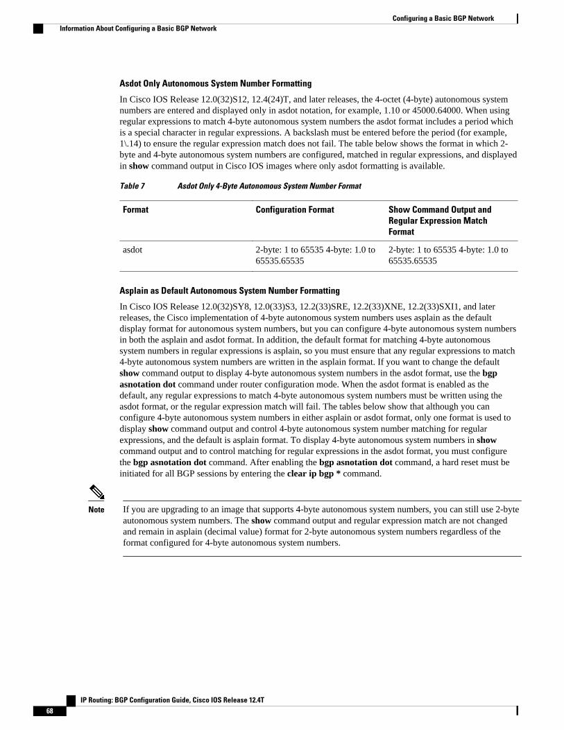
Asdot Only Autonomous System Number Formatting
In Cisco IOS Release 12.0(32)S12, 12.4(24)T, and later releases, the 4-octet (4-byte) autonomous systemnumbers are entered and displayed only in asdot notation, for example, 1.10 or 45000.64000. When usingregular expressions to match 4-byte autonomous system numbers the asdot format includes a period whichis a special character in regular expressions. A backslash must be entered before the period (for example,1\.14) to ensure the regular expression match does not fail. The table below shows the format in which 2-byte and 4-byte autonomous system numbers are configured, matched in regular expressions, and displayedin show command output in Cisco IOS images where only asdot formatting is available.
Table 7 Asdot Only 4-Byte Autonomous System Number Format
Format Configuration Format Show Command Output andRegular Expression MatchFormat
asdot 2-byte: 1 to 65535 4-byte: 1.0 to65535.65535
2-byte: 1 to 65535 4-byte: 1.0 to65535.65535
Asplain as Default Autonomous System Number Formatting
In Cisco IOS Release 12.0(32)SY8, 12.0(33)S3, 12.2(33)SRE, 12.2(33)XNE, 12.2(33)SXI1, and laterreleases, the Cisco implementation of 4-byte autonomous system numbers uses asplain as the defaultdisplay format for autonomous system numbers, but you can configure 4-byte autonomous system numbersin both the asplain and asdot format. In addition, the default format for matching 4-byte autonomoussystem numbers in regular expressions is asplain, so you must ensure that any regular expressions to match4-byte autonomous system numbers are written in the asplain format. If you want to change the defaultshow command output to display 4-byte autonomous system numbers in the asdot format, use the bgpasnotation dot command under router configuration mode. When the asdot format is enabled as thedefault, any regular expressions to match 4-byte autonomous system numbers must be written using theasdot format, or the regular expression match will fail. The tables below show that although you canconfigure 4-byte autonomous system numbers in either asplain or asdot format, only one format is used todisplay show command output and control 4-byte autonomous system number matching for regularexpressions, and the default is asplain format. To display 4-byte autonomous system numbers in showcommand output and to control matching for regular expressions in the asdot format, you must configurethe bgp asnotation dot command. After enabling the bgp asnotation dot command, a hard reset must beinitiated for all BGP sessions by entering the clear ip bgp * command.
Note If you are upgrading to an image that supports 4-byte autonomous system numbers, you can still use 2-byteautonomous system numbers. The show command output and regular expression match are not changedand remain in asplain (decimal value) format for 2-byte autonomous system numbers regardless of theformat configured for 4-byte autonomous system numbers.
Configuring a Basic BGP Network Information About Configuring a Basic BGP Network
IP Routing: BGP Configuration Guide, Cisco IOS Release 12.4T68
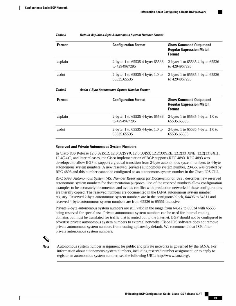
Table 8 Default Asplain 4-Byte Autonomous System Number Format
Format Configuration Format Show Command Output andRegular Expression MatchFormat
asplain 2-byte: 1 to 65535 4-byte: 65536to 4294967295
2-byte: 1 to 65535 4-byte: 65536to 4294967295
asdot 2-byte: 1 to 65535 4-byte: 1.0 to65535.65535
2-byte: 1 to 65535 4-byte: 65536to 4294967295
Table 9 Asdot 4-Byte Autonomous System Number Format
Format Configuration Format Show Command Output andRegular Expression MatchFormat
asplain 2-byte: 1 to 65535 4-byte: 65536to 4294967295
2-byte: 1 to 65535 4-byte: 1.0 to65535.65535
asdot 2-byte: 1 to 65535 4-byte: 1.0 to65535.65535
2-byte: 1 to 65535 4-byte: 1.0 to65535.65535
Reserved and Private Autonomous System Numbers
In Cisco IOS Release 12.0(32)S12, 12.0(32)SY8, 12.0(33)S3, 12.2(33)SRE, 12.2(33)XNE, 12.2(33)SXI1,12.4(24)T, and later releases, the Cisco implementation of BGP supports RFC 4893. RFC 4893 wasdeveloped to allow BGP to support a gradual transition from 2-byte autonomous system numbers to 4-byteautonomous system numbers. A new reserved (private) autonomous system number, 23456, was created byRFC 4893 and this number cannot be configured as an autonomous system number in the Cisco IOS CLI.
RFC 5398, Autonomous System (AS) Number Reservation for Documentation Use , describes new reservedautonomous system numbers for documentation purposes. Use of the reserved numbers allow configurationexamples to be accurately documented and avoids conflict with production networks if these configurationsare literally copied. The reserved numbers are documented in the IANA autonomous system numberregistry. Reserved 2-byte autonomous system numbers are in the contiguous block, 64496 to 64511 andreserved 4-byte autonomous system numbers are from 65536 to 65551 inclusive.
Private 2-byte autonomous system numbers are still valid in the range from 64512 to 65534 with 65535being reserved for special use. Private autonomous system numbers can be used for internal routingdomains but must be translated for traffic that is routed out to the Internet. BGP should not be configured toadvertise private autonomous system numbers to external networks. Cisco IOS software does not removeprivate autonomous system numbers from routing updates by default. We recommend that ISPs filterprivate autonomous system numbers.
Note Autonomous system number assignment for public and private networks is governed by the IANA. Forinformation about autonomous-system numbers, including reserved number assignment, or to apply toregister an autonomous system number, see the following URL: http://www.iana.org/.
Configuring a Basic BGP NetworkInformation About Configuring a Basic BGP Network
IP Routing: BGP Configuration Guide, Cisco IOS Release 12.4T 69

Cisco Implementation of 4-Byte Autonomous System NumbersIn Cisco IOS Release 12.0(32)SY8, 12.0(33)S3, 12.2(33)SRE, 12.2(33)XNE, 12.2(33)SXI1, and laterreleases, the Cisco implementation of 4-byte autonomous system numbers uses asplain--65538 forexample--as the default regular expression match and output display format for autonomous systemnumbers, but you can configure 4-byte autonomous system numbers in both the asplain format and theasdot format as described in RFC 5396. To change the default regular expression match and output displayof 4-byte autonomous system numbers to asdot format, use the bgp asnotation dot command followed bythe clear ip bgp * command to perform a hard reset of all current BGP sessions.
In Cisco IOS Release 12.0(32)S12, and 12.4(24)T, the Cisco implementation of 4-byte autonomous systemnumbers uses asdot--1.2 for example--as the only configuration format, regular expression match, andoutput display, with no asplain support. For an example of BGP peers in two autonomous systems using 4-byte numbers, see the figure below. To view a configuration example of the configuration between threeneighbor peers in separate 4-byte autonomous systems configured using asdot notation, see the ExamplesConfiguring a BGP Routing Process and Peers Using 4-Byte Autonomous System Numbers, page 148.
Cisco also supports RFC 4893, which was developed to allow BGP to support a gradual transition from 2-byte autonomous system numbers to 4-byte autonomous system numbers. To ensure a smooth transition,we recommend that all BGP speakers within an autonomous system that is identified using a 4-byteautonomous system number be upgraded to support 4-byte autonomous system numbers.
Note A new private autonomous system number, 23456, was created by RFC 4893, and this number cannot beconfigured as an autonomous system number in the Cisco IOS CLI.
Figure 8 BGP Peers in Two Autonomous Systems Using 4-Byte Numbers
BGP Peer Session EstablishmentWhen a BGP routing process establishes a peering session with a peer it goes through the following statechanges:
Cisco Implementation of 4-Byte Autonomous System Numbers Information About Configuring a Basic BGP Network
IP Routing: BGP Configuration Guide, Cisco IOS Release 12.4T70

• Idle--Initial state the BGP routing process enters when the routing process is enabled or when therouter is reset. In this state, the router waits for a start event, such as a peering configuration with aremote peer. After the router receives a TCP connection request from a remote peer, the router initiatesanother start event to wait for a timer before starting a TCP connection to a remote peer. If the router isreset then the peer is reset and the BGP routing process returns to the Idle state.
• Connect--The BGP routing process detects that a peer is trying to establish a TCP session with thelocal BGP speaker.
• Active--In this state, the BGP routing process tries to establish a TCP session with a peer router usingthe ConnectRetry timer. Start events are ignored while the BGP routing process is in the Active state.If the BGP routing process is reconfigured or if an error occurs, the BGP routing process will releasesystem resources and return to an Idle state.
• OpenSent--The TCP connection is established and the BGP routing process sends an OPEN messageto the remote peer, and transitions to the OpenSent state. The BGP routing process can receive otherOPEN messages in this state. If the connection fails, the BGP routing process transitions to the Activestate.
• OpenReceive--The BGP routing process receives the OPEN message from the remote peer and waitsfor an initial keepalive message from the remote peer. When a keepalive message is received, the BGProuting process transitions to the Established state. If a notification message is received, the BGProuting process transitions to the Idle state. If an error or configuration change occurs that affects thepeering session, the BGP routing process sends a notification message with the Finite State Machine(FSM) error code and then transitions to the Idle state.
• Established--The initial keepalive is received from the remote peer. Peering is now established withthe remote neighbor and the BGP routing process starts exchanging update message with the remotepeer. The hold timer restarts when an update or keepalive message is received. If the BGP processreceives an error notification, it will transition to the Idle state.
Cisco Implementation of BGP Global and Address Family ConfigurationCommands
The address family model for configuring BGP is based on splitting apart the configuration for eachaddress family. All commands that are independent of the address family are grouped together at thebeginning (highest level) of the configuration, and these are followed by separate submodes for commandsspecific to each address family (with the exception that commands relating to IPv4 unicast can also beentered at the beginning of the configuration). When a network operator configures BGP, the flow of BGPconfiguration categories is represented by the following bullets in order:
• Global configuration--Configuration that is applied to BGP in general, rather than to specificneighbors. For example, the network, redistribute, and bgp bestpath commands.
• Address family-dependent configuration--Configuration that applies to a specific address family suchas policy on an individual neighbor.
The relationship between BGP global and BGP address family-dependent configuration categories isshown in the table below.
Table 10 Relationships Between BGP Configuration Categories
BGP Configuration Category Configuration Sets Within Category
Global address family-independent One set of global address family-independentconfigurations
Cisco Implementation of BGP Global and Address Family Configuration CommandsInformation About Configuring a Basic BGP Network
IP Routing: BGP Configuration Guide, Cisco IOS Release 12.4T 71

BGP Configuration Category Configuration Sets Within Category
Address family-dependent One set of global address family-dependentconfigurations per address family
Note Address family configuration must be entered within the address family submode to which it applies.
The following is an example of BGP configuration statements showing the grouping of global addressfamily-independent and address family-dependent commands.
router bgp <AS> ! AF independent part neighbor <ip-address> <command> ! Session config; AF independent address-family ipv4 unicast ! AF dependant part neighbor <ip-address> <command> ! Policy config; AF dependant exit-address-family address-family ipv4 multicast ! AF dependant part neighbor <ip-address> <command> ! Policy config; AF dependant exit-address-family address-family ipv4 unicast vrf <vrf-name> ! VRF specific AS independent commands ! VRF specific AS dependant commands neighbor <ip-address> <command> ! Session config; AF independent neighbor <ip-address> <command> ! Policy config; AF dependant exit-address-family
The following example shows actual BGP commands that match the BGP configuration statements in theprevious example:
router bgp 45000 router-id 172.17.1.99 bgp log-neighbor-changes neighbor 192.168.1.2 remote-as 40000 neighbor 192.168.3.2 remote-as 50000 address-family ipv4 unicast neighbor 192.168.1.2 activate network 172.17.1.0 mask 255.255.255.0 exit-address-family address-family ipv4 multicast neighbor 192.168.3.2 activate neighbor 192.168.3.2 advertisement-interval 25 network 172.16.1.0 mask 255.255.255.0 exit-address-family address-family ipv4 vrf vpn1 neighbor 192.168.3.2 activate network 172.21.1.0 mask 255.255.255.0 exit-address-family
In Cisco IOS Releases 12.0(22)S, 12.2(15)T, and later releases, the bgp upgrade-cli command simplifiesthe migration of BGP networks and existing configurations from the network layer reachability information(NLRI) format to the address family format. Network operators can configure commands in the addressfamily identifier (AFI) format and save these command configurations to existing NLRI formattedconfigurations. The BGP hybrid command-line interface (CLI) does not add support for complete AFI andNLRI integration because of the limitations of the NLRI format. For complete support of AFI commandsand features, we recommend upgrading existing NLRI configurations with the bgp upgrade-cli command.For a configuration example of migrating BGP configurations from the NLRI format to the address familyformat, see .
Configuring a Basic BGP Network Information About Configuring a Basic BGP Network
IP Routing: BGP Configuration Guide, Cisco IOS Release 12.4T72
BGP Session ResetWhenever there is a change in the routing policy due to a configuration change, BGP peering sessions mustbe reset using the clear ip bgp command. Cisco IOS software support the following three mechanisms toreset BGP peering sessions:
• Hard reset--A hard reset tears down the specified peering sessions including the TCP connection anddeletes routes coming from the specified peer.
• Soft reset--A soft reset uses stored prefix information to reconfigure and activate BGP routing tableswithout tearing down existing peering sessions. Soft reconfiguration uses stored update information, atthe cost of additional memory for storing the updates, to allow you to apply new BGP policy withoutdisrupting the network. Soft reconfiguration can be configured for inbound or outbound sessions.
• Dynamic inbound soft reset--The route refresh capability, as defined in RFC 2918, allows the localrouter to reset inbound routing tables dynamically by exchanging route refresh requests to supportingpeers. The route refresh capability does not store update information locally for non disruptive policychanges. It instead relies on dynamic exchange with supporting peers. Route refresh must first beadvertised through BGP capability negotiation between peers. All BGP routers must support the routerefresh capability. To determine if a BGP router supports this capability, use the show ip bgpneighborscommand. The following message is displayed in the output when the router supports theroute refresh capability:
Received route refresh capability from peer.
The bgp soft-reconfig-backup command was introduced to configure BGP to perform inbound softreconfiguration for peers that do not support the route refresh capability. The configuration of thiscommand allows you to configure BGP to store updates (soft reconfiguration) only as necessary. Peers thatsupport the route refresh capability are unaffected by the configuration of this command.
BGP Route AggregationBGP peers store and exchange routing information and the amount of routing information increases asmore BGP speakers are configured. The use of route aggregation reduces the amount of informationinvolved. Aggregation is the process of combining the attributes of several different routes so that only asingle route is advertised. Aggregate prefixes use the classless interdomain routing (CIDR) principle tocombine contiguous networks into one classless set of IP addresses that can be summarized in routingtables. Fewer routes now need to be advertised.
Two methods are available in BGP to implement route aggregation. You can redistribute an aggregatedroute into BGP or you can use a form of conditional aggregation. Basic route redistribution involvescreating an aggregate route and then redistributing the routes into BGP. Conditional aggregation involvescreating an aggregate route and then advertising or suppressing the advertising of certain routes on the basisof route maps, autonomous system set path (AS-SET) information, or summary information.
The bgp suppress-inactive command configures BGP to not advertise inactive routes to any BGP peer. ABGP routing process can advertise routes that are not installed in the routing information database (RIB) toBGP peers by default. A route that is not installed into the RIB is an inactive route. Inactive routeadvertisement can occur, for example, when routes are advertised through common route aggregation.Inactive route advertisements can be suppressed to provide more consistent data forwarding.
BGP Aggregation Route AS-SET Information GenerationAS-SET information can be generated when BGP routes are aggregated using the aggregate-addresscommand. The path advertised for such a route is an AS-SET consisting of all the elements, including the
BGP Session ResetInformation About Configuring a Basic BGP Network
IP Routing: BGP Configuration Guide, Cisco IOS Release 12.4T 73

communities, contained in all the paths that are being summarized. If the AS-PATHs to be aggregated areidentical, only the AS-PATH is advertised. The ATOMIC-AGGREGATE attribute, set by default for theaggregate-address command, is not added to the AS-SET.
Routing Policy Change ManagementRouting policies for a peer include all the configurations for elements such as route map, distribute list,prefix list, and filter list that may impact inbound or outbound routing table updates. Whenever there is achange in the routing policy, the BGP session must be soft cleared, or soft reset, for the new policy to takeeffect. Performing inbound reset enables the new inbound policy configured on the router to take effect.Performing outbound reset causes the new local outbound policy configured on the router to take effectwithout resetting the BGP session. As a new set of updates is sent during outbound policy reset, a newinbound policy of the neighbor can also take effect. This means that after changing inbound policy youmust do an inbound reset on the local router or an outbound reset on the peer router. Outbound policychanges require an outbound reset on the local router or an inbound reset on the peer router.
There are two types of reset: hard reset and soft reset. The table below lists their advantages anddisadvantages.
Table 11 Advantages and Disadvantages of Hard and Soft Resets
Type of Reset Advantages Disadvantages
Hard reset No memory overhead. The prefixes in the BGP, IP, andForwarding Information Base(FIB) tables provided by theneighbor are lost. Notrecommended.
Outbound soft reset No configuration, no storing ofrouting table updates.
Does not reset inbound routingtable updates.
Dynamic inbound soft reset Does not clear the BGP sessionand cache.
Does not require storing ofrouting table updates, and has nomemory overhead.
Both BGP routers must supportthe route refresh capability (inCisco IOS Release 12.1 and laterreleases).
Note Does not reset outboundrouting table updates.
Routing Policy Change Management Information About Configuring a Basic BGP Network
IP Routing: BGP Configuration Guide, Cisco IOS Release 12.4T74

Type of Reset Advantages Disadvantages
Configured inbound soft reset(uses the neighbor soft-reconfiguration routerconfiguration command)
Can be used when both BGProuters do not support theautomatic route refreshcapability.
In Cisco IOS Release 12.3(14)T,the bgp soft-reconfig-backupcommand was introduced toconfigure inbound softreconfiguration for peers that donot support the route refreshcapability.
Requires preconfiguration.
Stores all received (inbound)routing policy updates withoutmodification; is memory-intensive.
Recommended only whenabsolutely necessary, such aswhen both BGP routers do notsupport the automatic routerefresh capability.
Note Does not reset outboundrouting table updates.
Once you have defined two routers to be BGP neighbors, they will form a BGP connection and exchangerouting information. If you subsequently change a BGP filter, weight, distance, version, or timer, or make asimilar configuration change, you must reset BGP connections for the configuration change to take effect.
A soft reset updates the routing table for inbound and outbound routing updates. Cisco IOS Release 12.1and later releases support soft reset without any prior configuration. This soft reset allows the dynamicexchange of route refresh requests and routing information between BGP routers, and the subsequentreadvertisement of the respective outbound routing table. There are two types of soft reset:
• When soft reset is used to generate inbound updates from a neighbor, it is called dynamic inbound softreset.
• When soft reset is used to send a new set of updates to a neighbor, it is called outbound soft reset.
To use soft reset without preconfiguration, both BGP peers must support the soft route refresh capability,which is advertised in the OPEN message sent when the peers establish a TCP session. Routers runningCisco IOS releases prior to Release 12.1 do not support the route refresh capability and must clear the BGPsession using the neighbor soft-reconfiguration router configuration command. Clearing the BGP sessionin this way will have a negative impact upon network operations and should be used only as a last resort.
Conditional BGP Route InjectionRoutes that are advertised through the BGP are commonly aggregated to minimize the number of routesthat are used and reduce the size of global routing tables. However, common route aggregation can obscuremore specific routing information that is more accurate but not necessary to forward packets to theirdestinations. Routing accuracy is obscured by common route aggregation because a prefix that representsmultiple addresses or hosts over a large topological area cannot be accurately reflected in a single route.Cisco IOS software provides several methods in which you can originate a prefix into BGP. The existingmethods include redistribution and using the network or aggregate-address command. These methodsassume the existence of more specific routing information (matching the route to be originated) in eitherthe routing table or the BGP table.
BGP conditional route injection allows you to originate a prefix into a BGP routing table without thecorresponding match. This feature allows more specific routes to be generated based on administrativepolicy or traffic engineering information in order to provide more specific control over the forwarding ofpackets to these more specific routes, which are injected into the BGP routing table only if the configuredconditions are met. Enabling this feature will allow you to improve the accuracy of common routeaggregation by conditionally injecting or replacing less specific prefixes with more specific prefixes. Only
Conditional BGP Route InjectionInformation About Configuring a Basic BGP Network
IP Routing: BGP Configuration Guide, Cisco IOS Release 12.4T 75

prefixes that are equal to or more specific than the original prefix may be injected. BGP conditional routeinjection is enabled with the bgp inject-map exist-mapcommand and uses two route maps (inject map andexist map) to install one (or more) more specific prefixes into a BGP routing table. The exist map specifiesthe prefixes that the BGP speaker will track. The inject map defines the prefixes that will be created andinstalled into the local BGP table.
BGP Peer GroupsOften, in a BGP network, many neighbors are configured with the same update policies (that is, the sameoutbound route maps, distribute lists, filter lists, update source, and so on). Neighbors with the same updatepolicies can be grouped into BGP peer groups to simplify configuration and, more importantly, to makeconfiguration updates more efficient. When you have many peers, this approach is highly recommended.
BGP Backdoor RoutesIn a BGP network topology with two border routers using eBGP to communicate to a number of differentautonomous systems, using eBGP to communicate between the two border routers may not be the mostefficient routing method. In the figure below, Router B as a BGP speaker will receive a route to Router Dthrough eBGP, but this route will traverse at least two autonomous systems. Router B and Router D arealso connected through an Enhanced Interior Gateway Routing Protocol (EIGRP) network (any IGP can beused here) and this route has a shorter path. EIGRP routes, however, have a default administrative distanceof 90 and eBGP routes have a default administrative distance of 20, so BGP will prefer the eBGP route.Changing the default administrative distances is not recommended because changing the administrativedistance may lead to routing loops. To cause BGP to prefer the EIGRP route, you can use the networkbackdoor command. BGP treats the network specified by the network backdoor command as a locallyassigned network, except that it does not advertise the specified network in BGP updates. In the figurebelow, this means that Router B will communicate to Router D using the shorter EIGRP route instead ofthe longer eBGP route.
Figure 9 BGP Backdoor Route Topology
BGP Peer Groups Information About Configuring a Basic BGP Network
IP Routing: BGP Configuration Guide, Cisco IOS Release 12.4T76

Peer Groups and BGP Update MessagesIn Cisco IOS software releases prior to Release 12.0(24)S, 12.2(18)S, or 12.3(4)T, BGP update messageswere grouped based on peer group configurations. This method of grouping neighbors for BGP updatemessage generation reduced the amount of system processing resources needed to scan the routing table.This method, however, had the following limitations:
• All neighbors that shared peer group configuration also had to share outbound routing policies.• All neighbors had to belong to the same peer group and address family. Neighbors configured in
different address families could not belong to different peer groups.
These limitations existed to balance optimal update generation and replication against peer groupconfiguration. These limitations could cause the network operator to configure smaller peer groups, whichreduced the efficiency of update message generation and limited the scalability of neighbor configuration.
BGP Update GroupThe introduction of the BGP (dynamic) update group in Cisco IOS Releases 12.0(24)S, 12.2(18)S,12.3(4)T, or 12.2(27)SBC, provides a different type of BGP peer grouping from existing BGP peer groups.Existing peer groups are not affected but peers with the same outbound policy configured that are notmembers of a current peer group can be grouped into an update group. The members of this update groupwill use the same update generation engine. When BGP update groups are configured an algorithmdynamically calculates the BGP update group membership based on outbound policies. Optimal BGPupdate message generation occurs automatically and independently. BGP neighbor configuration is nolonger restricted by outbound routing policies, and update groups can belong to different address families.
BGP Dynamic Update Group ConfigurationIn Cisco IOS Release 12.0(24)S, 12.2(18)S, 12.3(4)T, 12.2(27)SBC, and later releases, a new algorithmwas introduced that dynamically calculates and optimizes update groups of neighbors that share the sameoutbound policies and can share the same update messages. No configuration is required to enable the BGPdynamic update group and the algorithm runs automatically. When a change to outbound policy occurs, therouter automatically recalculates update group memberships and applies the changes by triggering anoutbound soft reset after a 1-minute timer expires. This behavior is designed to provide the networkoperator with time to change the configuration if a mistake is made. You can manually enable an outboundsoft reset before the timer expires by entering the clear ip bgp ip-address soft outcommand.
Note In Cisco IOS Release 12.0(22)S, 12.2(14)S, 12.3(2)T, and prior releases, the update group recalculationdelay timer is set to 3 minutes.
For the best optimization of BGP update group generation, we recommend that the network operator keepsoutbound routing policy the same for neighbors that have similar outbound policies.
BGP Peer TemplatesTo address some of the limitations of peer groups such as configuration management, BGP peer templateswere introduced to support the BGP update group configuration.
A peer template is a configuration pattern that can be applied to neighbors that share policies. Peertemplates are reusable and support inheritance, which allows the network operator to group and applydistinct neighbor configurations for BGP neighbors that share policies. Peer templates also allow the
Peer Groups and BGP Update MessagesInformation About Configuring a Basic BGP Network
IP Routing: BGP Configuration Guide, Cisco IOS Release 12.4T 77

network operator to define very complex configuration patterns through the capability of a peer template toinherit a configuration from another peer template.
There are two types of peer templates:
• Peer session templates are used to group and apply the configuration of general session commands thatare common to all address family and NLRI configuration modes.
• Peer policy templates are used to group and apply the configuration of commands that are appliedwithin specific address families and NLRI configuration modes.
Peer templates improve the flexibility and enhance the capability of neighbor configuration. Peer templatesalso provide an alternative to peer group configuration and overcome some limitations of peer groups. BGPpeer routers using peer templates also benefit from automatic update group configuration. With theconfiguration of the BGP peer templates and the support of the BGP dynamic update peer groups, thenetwork operator no longer needs to configure peer groups in BGP and the network can benefit fromimproved configuration flexibility and faster convergence.
Note A BGP neighbor cannot be configured to work with both peer groups and peer templates. A BGP neighborcan be configured to belong only to a peer group or to inherit policies from peer templates.
The following restrictions apply to the peer policy templates:
• A peer policy template can directly or indirectly inherit up to eight peer policy templates.• A BGP neighbor cannot be configured to work with both peer groups and peer templates. A BGP
neighbor can be configured to belong only to a peer group or to inherit policies only from peertemplates.
Inheritance in Peer TemplatesThe inheritance capability is a key component of peer template operation. Inheritance in a peer template issimilar to node and tree structures commonly found in general computing, for example, file and directorytrees. A peer template can directly or indirectly inherit the configuration from another peer template. Thedirectly inherited peer template represents the tree in the structure. The indirectly inherited peer templaterepresents a node in the tree. Because each node also supports inheritance, branches can be created thatapply the configurations of all indirectly inherited peer templates within a chain back to the directlyinherited peer template or the source of the tree. This structure eliminates the need to repeat configurationstatements that are commonly reapplied to groups of neighbors because common configuration statementscan be applied once and then indirectly inherited by peer templates that are applied to neighbor groups withcommon configurations. Configuration statements that are duplicated separately within a node and a treeare filtered out at the source of the tree by the directly inherited template. A directly inherited template willoverwrite any indirectly inherited statements that are duplicated in the directly inherited template.
Inheritance expands the scalability and flexibility of neighbor configuration by allowing you to chaintogether peer templates configurations to create simple configurations that inherit common configurationstatements or complex configurations that apply very specific configuration statements along with commoninherited configurations. Specific details about configuring inheritance in peer session templates and peerpolicy templates are provided in the following sections.
When BGP neighbors use inherited peer templates it can be difficult to determine which policies areassociated with a specific template. In Cisco IOS 12.0(25)S, 12.4(11)T, 12.2(33)SRB, 12.2(33)SB, andlater releases, the detail keyword was added to the show ip bgp template peer-policy command to displaythe detailed configuration of local and inherited policies associated with a specific template.
Inheritance in Peer Templates Information About Configuring a Basic BGP Network
IP Routing: BGP Configuration Guide, Cisco IOS Release 12.4T78
Peer Session TemplatesPeer session templates are used to group and apply the configuration of general session commands togroups of neighbors that share session configuration elements. General session commands that are commonfor neighbors that are configured in different address families can be configured within the same peersession template. Peer session templates are created and configured in peer session configuration mode.Only general session commands can be configured in a peer session template. The following generalsession commands are supported by peer session templates:
• description• disable-connected-check• ebgp-multihop• exit peer-session• inherit peer-session• local-as• password• remote-as• shutdown• timers• translate-update• update-source• version
General session commands can be configured once in a peer session template and then applied to manyneighbors through the direct application of a peer session template or through indirect inheritance from apeer session template. The configuration of peer session templates simplifies the configuration of generalsession commands that are commonly applied to all neighbors within an autonomous system.
Peer session templates support direct and indirect inheritance. A peer can be configured with only one peersession template at a time, and that peer session template can contain only one indirectly inherited peersession template.
Note If you attempt to configure more than one inherit statement with a single peer session template, an errormessage will be displayed.
This behavior allows a BGP neighbor to directly inherit only one session template and indirectly inherit upto seven additional peer session templates. This allows you to apply up to a maximum of eight peer sessionconfigurations to a neighbor: the configuration from the directly inherited peer session template and theconfigurations from up to seven indirectly inherited peer session templates. Inherited peer sessionconfigurations are evaluated first and applied starting with the last node in the branch and ending with thedirectly applied peer session template configuration at the source of the tree. The directly applied peersession template will have priority over inherited peer session template configurations. Any configurationstatements that are duplicated in inherited peer session templates will be overwritten by the directly appliedpeer session template. So, if a general session command is reapplied with a different value, the subsequentvalue will have priority and overwrite the previous value that was configured in the indirectly inheritedtemplate. The following examples illustrate the use of this feature.
In the following example, the general session command remote-as 1 is applied in the peer session templatenamed SESSION-TEMPLATE-ONE:
template peer-session SESSION-TEMPLATE-ONE
Peer Session TemplatesInformation About Configuring a Basic BGP Network
IP Routing: BGP Configuration Guide, Cisco IOS Release 12.4T 79

remote-as 1 exit peer-session
Peer session templates support only general session commands. BGP policy configuration commands thatare configured only for a specific address family or NLRI configuration mode are configured with peerpolicy templates.
Peer Policy TemplatesPeer policy templates are used to group and apply the configuration of commands that are applied withinspecific address families and NLRI configuration mode. Peer policy templates are created and configuredin peer policy configuration mode. BGP policy commands that are configured for specific address familiesare configured in a peer policy template. The following BGP policy commands are supported by peerpolicy templates:
• advertisement-interval• allowas-in• as-override• capability• default-originate• distribute-list• dmzlink-bw• exit-peer-policy• filter-list• inherit peer-policy• maximum-prefix• next-hop-self• next-hop-unchanged• prefix-list• remove-private-as• route-map• route-reflector-client• send-community• send-label• soft-reconfiguration• unsuppress-map• weight
Peer policy templates are used to configure BGP policy commands that are configured for neighbors thatbelong to specific address families. Like peer session templates, peer policy templates are configured onceand then applied to many neighbors through the direct application of a peer policy template or throughinheritance from peer policy templates. The configuration of peer policy templates simplifies theconfiguration of BGP policy commands that are applied to all neighbors within an autonomous system.
Like peer session templates, a peer policy template supports inheritance. However, there are minordifferences. A directly applied peer policy template can directly or indirectly inherit configurations from upto seven peer policy templates. So, a total of eight peer policy templates can be applied to a neighbor orneighbor group. Inherited peer policy templates are configured with sequence numbers like route maps. Aninherited peer policy template, like a route map, is evaluated starting with the inherit statement with thelowest sequence number and ending with the highest sequence number. However, there is a difference; apeer policy template will not collapse like a route map. Every sequence is evaluated, and if a BGP policy
Peer Policy Templates Information About Configuring a Basic BGP Network
IP Routing: BGP Configuration Guide, Cisco IOS Release 12.4T80

command is reapplied with a different value, it will overwrite any previous value from a lower sequencenumber.
The directly applied peer policy template and the inherit statement with the highest sequence number willalways have priority and be applied last. Commands that are reapplied in subsequent peer templates willalways overwrite the previous values. This behavior is designed to allow you to apply common policyconfigurations to large neighbor groups and specific policy configurations only to certain neighbors andneighbor groups without duplicating individual policy configuration commands.
Peer policy templates support only policy configuration commands. BGP policy configuration commandsthat are configured only for specific address families are configured with peer policy templates.
The configuration of peer policy templates simplifies and improves the flexibility of BGP configuration. Aspecific policy can be configured once and referenced many times. Because a peer policy supports up toeight levels of inheritance, very specific and very complex BGP policies can also be created.
BGP IPv6 Neighbor Activation Under the IPv4 Address FamilyPrior to Cisco IOS Release 12.2(33)SRE4, by default, both IPv6 and IPv4 capability is exchanged with aBGP peer that has an IPv6 address. When an IPv6 peer is configured, that neighbor is automaticallyactivated under the IPv4 unicast address family.
Beginning with Cisco IOS Release 12.2(33)SRE4, when a new IPv6 neighbor is being configured, it is nolonger automatically activated under the IPv4 address family. You can manually activate the IPv6 neighborunder the IPv4 address family if, for example, you have a dual stack environment and want to send IPv6and IPv4 prefixes.
If you do not want an existing IPv6 peer to be activated under the IPv4 address family, you can manuallydeactivate the peer with the no neighbor activate command. Until then, existing configurations thatactivate an IPv6 neighbor under the IPv4 unicast address family will continue to try to establish a session.
How to Configure a Basic BGP NetworkConfiguring a basic BGP network consists of a few required tasks and many optional tasks. A BGP routingprocess must be configured and BGP peers must be configured, preferably using the address familyconfiguration model. If the BGP peers are part of a VPN network, the BGP peers must be configured usingthe IPv4 VRF address family task. The other tasks in the following list are optional:
• Configuring a BGP Routing Process, page 82• Configuring a BGP Peer, page 85• Configuring a BGP Routing Process and Peers Using 4-Byte Autonomous System Numbers, page88• Modifying the Default Output and Regular Expression Match Format for 4-Byte Autonomous SystemNumbers, page 92• Configuring a BGP Peer for the IPv4 VRF Address Family, page 96• Customizing a BGP Peer, page 99• Removing BGP Configuration Commands Using a Redistribution, page 105• Monitoring and Maintaining Basic BGP, page 107• Aggregating Route Prefixes Using BGP, page 112• Originating BGP Routes, page 122• Configuring a BGP Peer Group, page 130• Configuring Peer Session Templates, page 132
BGP IPv6 Neighbor Activation Under the IPv4 Address FamilyHow to Configure a Basic BGP Network
IP Routing: BGP Configuration Guide, Cisco IOS Release 12.4T 81

• Configuring Peer Policy Templates, page 138
• Monitoring and Maintaining BGP Dynamic Update Groups, page 145
Configuring a BGP Routing ProcessPerform this task to configure a BGP routing process. You must perform the required steps at least once toenable BGP. The optional steps here allow you to configure additional features in your BGP network.Several of the features, such as logging neighbor resets and immediate reset of a peer when its link goesdown, are enabled by default but are presented here to enhance your understanding of how your BGPnetwork operates.
Note A router that runs Cisco IOS software can be configured to run only one BGP routing process and to be amember of only one BGP autonomous system. However, a BGP routing process and autonomous systemcan support multiple concurrent BGP address family and subaddress family configurations.
The configuration in this task is done at Router A in the figure below and would need to be repeated withappropriate changes to the IP addresses (for example, at Router B) to fully achieve a BGP process betweenthe two routers. No address family is configured here for the BGP routing process so routing informationfor the IPv4 unicast address family is advertised by default.
Figure 10 BGP Topology with Two Autonomous Systems
Configuring a BGP Routing Process How to Configure a Basic BGP Network
IP Routing: BGP Configuration Guide, Cisco IOS Release 12.4T82

SUMMARY STEPS
1. enable
2. configure terminal
3. router bgp autonomous-system-number
4. network network-number [mask network-mask][route-map route-map-name]
5. bgp router-id ip-address
6. timers bgp keepalive holdtime
7. bgp fast-external-fallover
8. bgp log-neighbor-changes
9. end
10. show ip bgp [network] [network-mask]
DETAILED STEPS
Command or Action Purpose
Step 1 enable
Example:
Router> enable
Enables privileged EXEC mode.
• Enter your password if prompted.
Step 2 configure terminal
Example:
Router# configure terminal
Enters global configuration mode.
Step 3 router bgp autonomous-system-number
Example:
Router(config)# router bgp 40000
Configures a BGP routing process, and enters router configuration mode forthe specified routing process.
• Use the autonomous-system-number argument to specify an integer, from0 and 65534, that identifies the router to other BGP speakers.
Step 4 network network-number [mask network-mask][route-map route-map-name]
Example:
Router(config-router)# network 10.1.1.0 mask 255.255.255.0
(Optional) Specifies a network as local to this autonomous system and adds itto the BGP routing table.
• For exterior protocols the network command controls which networksare advertised. Interior protocols use the network command to determinewhere to send updates.
Configuring a Basic BGP NetworkHow to Configure a Basic BGP Network
IP Routing: BGP Configuration Guide, Cisco IOS Release 12.4T 83

Command or Action Purpose
Step 5 bgp router-id ip-address
Example:
Router(config-router)# bgp router-id 10.1.1.99
(Optional) Configures a fixed 32-bit router ID as the identifier of the localrouter running BGP.
• Use the ip-address argument to specify a unique router ID within thenetwork.
Note Configuring a router ID using the bgp router-id command resets allactive BGP peering sessions.
Step 6 timers bgp keepalive holdtime
Example:
Router(config-router)# timers bgp 70 120
(Optional) Sets BGP network timers.
• Use the keepalive argument to specify the frequency, in seconds, withwhich the software sends keepalive messages to its BGP peer. Bydefault, the keepalive timer is set to 60 seconds.
• Use the holdtime argument to specify the interval, in seconds, after notreceiving a keepalive message that the software declares a BGP peerdead. By default, the holdtime timer is set to 180 seconds.
Step 7 bgp fast-external-fallover
Example:
Router(config-router)# bgp fast-external-fallover
(Optional) Enables the automatic resetting of BGP sessions.
• By default, the BGP sessions of any directly adjacent external peers arereset if the link used to reach them goes down.
Step 8 bgp log-neighbor-changes
Example:
Router(config-router)# bgp log-neighbor-changes
(Optional) Enables logging of BGP neighbor status changes (up or down) andneighbor resets.
• Use this command for troubleshooting network connectivity problemsand measuring network stability. Unexpected neighbor resets mightindicate high error rates or high packet loss in the network and should beinvestigated.
Step 9 end
Example:
Router(config-router)# end
Exits router configuration mode and enters privileged EXEC mode.
Step 10 show ip bgp [network] [network-mask]
Example:
Router# show ip bgp
(Optional) Displays the entries in the BGP routing table.
Note Only the syntax applicable to this task is used in this example. Formore details, see the Cisco IOS IP Routing: BGP Command Reference.
Configuring a Basic BGP Network How to Configure a Basic BGP Network
IP Routing: BGP Configuration Guide, Cisco IOS Release 12.4T84
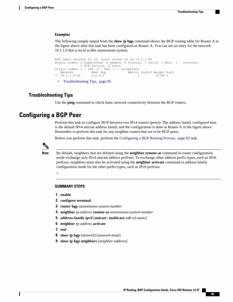
Examples
The following sample output from the show ip bgp command shows the BGP routing table for Router A inthe figure above after this task has been configured on Router A. You can see an entry for the network10.1.1.0 that is local to this autonomous system.
BGP table version is 12, local router ID is 10.1.1.99Status codes: s suppressed, d damped, h history, * valid, > best, i - internal, r RIB-failure, S StaleOrigin codes: i - IGP, e - EGP, ? - incomplete Network Next Hop Metric LocPrf Weight Path*> 10.1.1.0/24 0.0.0.0 0 32768 i
• Troubleshooting Tips, page 85
Troubleshooting TipsUse the ping command to check basic network connectivity between the BGP routers.
Configuring a BGP PeerPerform this task to configure BGP between two IPv4 routers (peers). The address family configured hereis the default IPv4 unicast address family and the configuration is done at Router A in the figure above.Remember to perform this task for any neighbor routers that are to be BGP peers.
Before you perform this task, perform the Configuring a BGP Routing Process, page 82 task.
Note By default, neighbors that are defined using the neighbor remote-as command in router configurationmode exchange only IPv4 unicast address prefixes. To exchange other address prefix types, such as IPv6prefixes, neighbors must also be activated using the neighbor activate command in address familyconfiguration mode for the other prefix types, such as IPv6 prefixes.
>
SUMMARY STEPS
1. enable
2. configure terminal
3. router bgp autonomous-system-number
4. neighbor ip-address remote-as autonomous-system-number
5. address-family ipv4 [unicast | multicast| vrf vrf-name]
6. neighbor ip-address activate
7. end
8. show ip bgp [network] [network-mask]
9. show ip bgp neighbors [neighbor-address]
Configuring a BGP PeerTroubleshooting Tips
IP Routing: BGP Configuration Guide, Cisco IOS Release 12.4T 85

DETAILED STEPS
Command or Action Purpose
Step 1 enable
Example:
Router> enable
Enables privileged EXEC mode.
• Enter your password if prompted.
Step 2 configure terminal
Example:
Router# configure terminal
Enters global configuration mode.
Step 3 router bgp autonomous-system-number
Example:
Router(config)# router bgp 40000
Enters router configuration mode for the specified routing process.
Step 4 neighbor ip-address remote-as autonomous-system-number
Example:
Router(config-router)# neighbor 192.168.1.1 remote-as 45000
Adds the IP address of the neighbor in the specified autonomous systemto the IPv4 multiprotocol BGP neighbor table of the local router.
Step 5 address-family ipv4 [unicast | multicast| vrfvrf-name]
Example:
Router(config-router)# address-family ipv4 unicast
Specifies the IPv4 address family and enters address familyconfiguration mode.
• The unicast keyword specifies the IPv4 unicast address family. Bydefault, the router is placed in configuration mode for the IPv4unicast address family if the unicast keyword is not specified withthe address-family ipv4 command.
• The multicast keyword specifies IPv4 multicast address prefixes.• The vrf keyword and vrf-name argument specify the name of the
virtual routing and forwarding (VRF) instance to associate withsubsequent IPv4 address family configuration mode commands.
Step 6 neighbor ip-address activate
Example:
Router(config-router-af)# neighbor 192.168.1.1 activate
Enables the neighbor to exchange prefixes for the IPv4 unicast addressfamily with the local router.
Configuring a Basic BGP Network Troubleshooting Tips
IP Routing: BGP Configuration Guide, Cisco IOS Release 12.4T86

Command or Action Purpose
Step 7 end
Example:
Router(config-router-af)# end
Exits address family configuration mode and enters privileged EXECmode.
Step 8 show ip bgp [network] [network-mask]
Example:
Router# show ip bgp
(Optional) Displays the entries in the BGP routing table.
Note Only the syntax applicable to this task is used in this example.For more details, see the Cisco IOS IP Routing: BGP CommandReference.
Step 9 show ip bgp neighbors [neighbor-address]
Example:
Router(config-router-af)# show ip bgp neighbors 192.168.2.2
(Optional) Displays information about the TCP and BGP connections toneighbors.
Note Only the syntax applicable to this task is used in this example.For more details, see the Cisco IOS IP Routing: BGP CommandReference.
Examples
The following sample output from the show ip bgp command shows the BGP routing table for Router A inthe figure above after this task has been configured on Router A and Router B. You can now see an entryfor the network 172.17.1.0 in autonomous system 45000.
BGP table version is 13, local router ID is 10.1.1.99Status codes: s suppressed, d damped, h history, * valid, > best, i - internal, r RIB-failure, S StaleOrigin codes: i - IGP, e - EGP, ? - incomplete Network Next Hop Metric LocPrf Weight Path*> 10.1.1.0/24 0.0.0.0 0 32768 i*> 172.17.1.0/24 192.168.1.1 0 0 45000 i
The following sample output from the show ip bgp neighbors command shows information about the TCPand BGP connections to the BGP neighbor 192.168.1.1 of Router A in the figure above after this task hasbeen configured on Router A:
BGP neighbor is 192.168.1.1, remote AS 45000, external link BGP version 4, remote router ID 172.17.1.99 BGP state = Established, up for 00:06:55 Last read 00:00:15, last write 00:00:15, hold time is 120, keepalive intervals Configured hold time is 120,keepalive interval is 70 seconds, Minimum holdtims Neighbor capabilities: Route refresh: advertised and received (old & new) Address family IPv4 Unicast: advertised and received Message statistics: InQ depth is 0 OutQ depth is 0 Sent Rcvd Opens: 1 1 Notifications: 0 0 Updates: 1 2 Keepalives: 13 13 Route Refresh: 0 0 Total: 15 16 Default minimum time between advertisement runs is 30 seconds
Configuring a Basic BGP NetworkTroubleshooting Tips
IP Routing: BGP Configuration Guide, Cisco IOS Release 12.4T 87

For address family: IPv4 Unicast BGP table version 13, neighbor version 13/0 Output queue size : 0 Index 1, Offset 0, Mask 0x2 1 update-group member Sent Rcvd Prefix activity: ---- ---- Prefixes Current: 1 1 (Consumes 52 bytes) Prefixes Total: 1 1 Implicit Withdraw: 0 0 Explicit Withdraw: 0 0 Used as bestpath: n/a 1 Used as multipath: n/a 0 Outbound Inbound Local Policy Denied Prefixes: -------- ------- AS_PATH loop: n/a 1 Bestpath from this peer: 1 n/a Total: 1 1 Number of NLRIs in the update sent: max 0, min 0 Connections established 1; dropped 0 Last reset neverConnection state is ESTAB, I/O status: 1, unread input bytes: 0 Connection is ECN DisabledLocal host: 192.168.1.2, Local port: 179Foreign host: 192.168.1.1, Foreign port: 37725Enqueued packets for retransmit: 0, input: 0 mis-ordered: 0 (0 bytes)Event Timers (current time is 0x12F4F2C):Timer Starts Wakeups NextRetrans 14 0 0x0TimeWait 0 0 0x0AckHold 13 8 0x0SendWnd 0 0 0x0KeepAlive 0 0 0x0GiveUp 0 0 0x0PmtuAger 0 0 0x0DeadWait 0 0 0x0iss: 165379618 snduna: 165379963 sndnxt: 165379963 sndwnd: 16040irs: 3127821601 rcvnxt: 3127821993 rcvwnd: 15993 delrcvwnd: 391SRTT: 254 ms, RTTO: 619 ms, RTV: 365 ms, KRTT: 0 msminRTT: 12 ms, maxRTT: 300 ms, ACK hold: 200 msFlags: passive open, nagle, gen tcbsIP Precedence value : 6Datagrams (max data segment is 1460 bytes):Rcvd: 20 (out of order: 0), with data: 15, total data bytes: 391Sent: 22 (retransmit: 0, fastretransmit: 0, partialack: 0, Second Congestion: 04
• Troubleshooting Tips, page 88• What to Do Next, page 88
Troubleshooting TipsUse the ping command to verify basic network connectivity between the BGP routers.
What to Do NextIf you have BGP peers in a VPN, proceed to theConfiguring a BGP Peer for the IPv4 VRF AddressFamily, page 96. If you do not have BGP peers in a VPN, proceed to the Customizing a BGP Peer, page99.
Configuring a BGP Routing Process and Peers Using 4-Byte AutonomousSystem Numbers
Perform this task to configure a BGP routing process and BGP peers when the BGP peers are located in 4-byte autonomous system numbers. The address family configured here is the default IPv4 unicast address
Configuring a BGP Routing Process and Peers Using 4-Byte Autonomous System Numbers Troubleshooting Tips
IP Routing: BGP Configuration Guide, Cisco IOS Release 12.4T88

family, and the configuration is done at Router B in the figure above (in the "Cisco Implementation of 4-Byte Autonomous System Numbers" section). The 4-byte autonomous system numbers in this task areformatted in the default asplain (decimal value) format; for example, Router B is in autonomous systemnumber 65538 in the figure above. Remember to perform this task for any neighbor routers that are to beBGP peers.
For more details about 4-byte autonomous system number formats, see the BGP Autonomous SystemNumber Formats, page 67 and the Cisco Implementation of 4-Byte Autonomous System Numbers, page70.
This task requires Cisco IOS Release 12.0(32)SY8, 12.2(33)SXI1, or a later release to be running on therouter.
Note By default, neighbors that are defined using the neighbor remote-as command in router configurationmode exchange only IPv4 unicast address prefixes. To exchange other address prefix types, such as IPv6prefixes, neighbors must also be activated using the neighbor activate command in address familyconfiguration mode for the other prefix types.
>
SUMMARY STEPS
1. enable
2. configure terminal
3. router bgp autonomous-system-number
4. neighbor ip-address remote-as autonomous-system-number
5. Repeat Step 4 to define other BGP neighbors, as required.
6. address-family ipv4 [unicast | multicast| vrf vrf-name]
7. neighbor ip-address activate
8. Repeat Step 7 to activate other BGP neighbors, as required.
9. network network-number [mask network-mask][route-map route-map-name]
10. end
11. show ip bgp [network] [network-mask]
12. show ip bgp summary
DETAILED STEPS
Command or Action Purpose
Step 1 enable
Example:
Router> enable
Enables privileged EXEC mode.
• Enter your password if prompted.
Configuring a Basic BGP NetworkWhat to Do Next
IP Routing: BGP Configuration Guide, Cisco IOS Release 12.4T 89
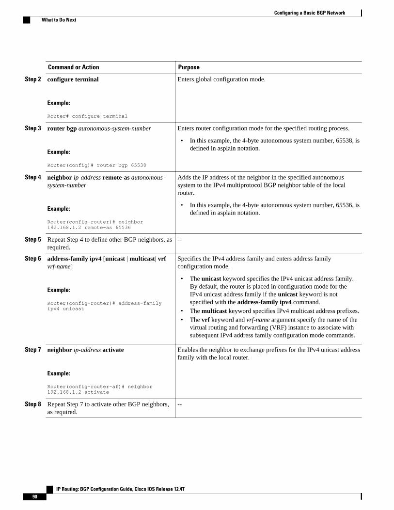
Command or Action Purpose
Step 2 configure terminal
Example:
Router# configure terminal
Enters global configuration mode.
Step 3 router bgp autonomous-system-number
Example:
Router(config)# router bgp 65538
Enters router configuration mode for the specified routing process.
• In this example, the 4-byte autonomous system number, 65538, isdefined in asplain notation.
Step 4 neighbor ip-address remote-as autonomous-system-number
Example:
Router(config-router)# neighbor 192.168.1.2 remote-as 65536
Adds the IP address of the neighbor in the specified autonomoussystem to the IPv4 multiprotocol BGP neighbor table of the localrouter.
• In this example, the 4-byte autonomous system number, 65536, isdefined in asplain notation.
Step 5 Repeat Step 4 to define other BGP neighbors, asrequired.
--
Step 6 address-family ipv4 [unicast | multicast| vrfvrf-name]
Example:
Router(config-router)# address-family ipv4 unicast
Specifies the IPv4 address family and enters address familyconfiguration mode.
• The unicast keyword specifies the IPv4 unicast address family.By default, the router is placed in configuration mode for theIPv4 unicast address family if the unicast keyword is notspecified with the address-family ipv4 command.
• The multicast keyword specifies IPv4 multicast address prefixes.• The vrf keyword and vrf-name argument specify the name of the
virtual routing and forwarding (VRF) instance to associate withsubsequent IPv4 address family configuration mode commands.
Step 7 neighbor ip-address activate
Example:
Router(config-router-af)# neighbor 192.168.1.2 activate
Enables the neighbor to exchange prefixes for the IPv4 unicast addressfamily with the local router.
Step 8 Repeat Step 7 to activate other BGP neighbors,as required.
--
Configuring a Basic BGP Network What to Do Next
IP Routing: BGP Configuration Guide, Cisco IOS Release 12.4T90
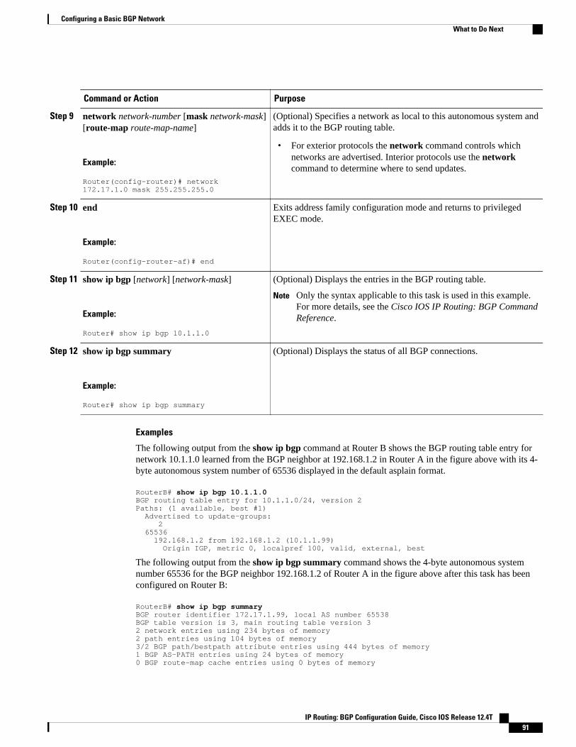
Command or Action Purpose
Step 9 network network-number [mask network-mask][route-map route-map-name]
Example:
Router(config-router)# network 172.17.1.0 mask 255.255.255.0
(Optional) Specifies a network as local to this autonomous system andadds it to the BGP routing table.
• For exterior protocols the network command controls whichnetworks are advertised. Interior protocols use the networkcommand to determine where to send updates.
Step 10 end
Example:
Router(config-router-af)# end
Exits address family configuration mode and returns to privilegedEXEC mode.
Step 11 show ip bgp [network] [network-mask]
Example:
Router# show ip bgp 10.1.1.0
(Optional) Displays the entries in the BGP routing table.
Note Only the syntax applicable to this task is used in this example.For more details, see the Cisco IOS IP Routing: BGP CommandReference.
Step 12 show ip bgp summary
Example:
Router# show ip bgp summary
(Optional) Displays the status of all BGP connections.
Examples
The following output from the show ip bgp command at Router B shows the BGP routing table entry fornetwork 10.1.1.0 learned from the BGP neighbor at 192.168.1.2 in Router A in the figure above with its 4-byte autonomous system number of 65536 displayed in the default asplain format.
RouterB# show ip bgp 10.1.1.0BGP routing table entry for 10.1.1.0/24, version 2Paths: (1 available, best #1) Advertised to update-groups: 2 65536 192.168.1.2 from 192.168.1.2 (10.1.1.99) Origin IGP, metric 0, localpref 100, valid, external, best
The following output from the show ip bgp summary command shows the 4-byte autonomous systemnumber 65536 for the BGP neighbor 192.168.1.2 of Router A in the figure above after this task has beenconfigured on Router B:
RouterB# show ip bgp summaryBGP router identifier 172.17.1.99, local AS number 65538BGP table version is 3, main routing table version 32 network entries using 234 bytes of memory2 path entries using 104 bytes of memory3/2 BGP path/bestpath attribute entries using 444 bytes of memory1 BGP AS-PATH entries using 24 bytes of memory0 BGP route-map cache entries using 0 bytes of memory
Configuring a Basic BGP NetworkWhat to Do Next
IP Routing: BGP Configuration Guide, Cisco IOS Release 12.4T 91

0 BGP filter-list cache entries using 0 bytes of memoryBGP using 806 total bytes of memoryBGP activity 2/0 prefixes, 2/0 paths, scan interval 60 secsNeighbor V AS MsgRcvd MsgSent TblVer InQ OutQ Up/Down Stated192.168.1.2 4 65536 6 6 3 0 0 00:01:33 1
• Troubleshooting Tips, page 92
Troubleshooting TipsUse the ping command to verify basic network connectivity between the BGP routers.
Modifying the Default Output and Regular Expression Match Format for 4-Byte Autonomous System Numbers
Perform this task to modify the default output format for 4-byte autonomous system numbers from asplainformat to asdot notation format. The show ip bgp summary command is used to display the changes inoutput format for the 4-byte autonomous system numbers.
For more details about 4-byte autonomous system number formats, see the BGP Autonomous SystemNumber Formats, page 67.
This example requires Cisco IOS Release 12.0(32)SY8, 12.0(33)S3, 12.2(33)SRE, 12.2(33)XNE,12.2(33)SXI1, or a later release, to be running on the router.
SUMMARY STEPS
1. enable
2. show ip bgp summary
3. configure terminal
4. router bgp autonomous-system-number
5. bgp asnotation dot
6. end
7. clear ip bgp *
8. show ip bgp summary
9. show ip bgp regexp regexp
10. configure terminal
11. router bgp autonomous-system-number
12. no bgp asnotation dot
13. end
14. clear ip bgp *
Modifying the Default Output and Regular Expression Match Format for 4-Byte Autonomous System Numbers Troubleshooting Tips
IP Routing: BGP Configuration Guide, Cisco IOS Release 12.4T92
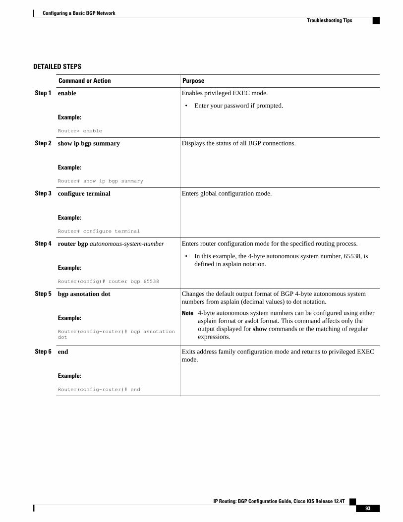
DETAILED STEPS
Command or Action Purpose
Step 1 enable
Example:
Router> enable
Enables privileged EXEC mode.
• Enter your password if prompted.
Step 2 show ip bgp summary
Example:
Router# show ip bgp summary
Displays the status of all BGP connections.
Step 3 configure terminal
Example:
Router# configure terminal
Enters global configuration mode.
Step 4 router bgp autonomous-system-number
Example:
Router(config)# router bgp 65538
Enters router configuration mode for the specified routing process.
• In this example, the 4-byte autonomous system number, 65538, isdefined in asplain notation.
Step 5 bgp asnotation dot
Example:
Router(config-router)# bgp asnotation dot
Changes the default output format of BGP 4-byte autonomous systemnumbers from asplain (decimal values) to dot notation.
Note 4-byte autonomous system numbers can be configured using eitherasplain format or asdot format. This command affects only theoutput displayed for show commands or the matching of regularexpressions.
Step 6 end
Example:
Router(config-router)# end
Exits address family configuration mode and returns to privileged EXECmode.
Configuring a Basic BGP NetworkTroubleshooting Tips
IP Routing: BGP Configuration Guide, Cisco IOS Release 12.4T 93

Command or Action Purpose
Step 7 clear ip bgp *
Example:
Router# clear ip bgp *
Clears and resets all current BGP sessions.
• In this example, a hard reset is performed to ensure that the 4-byteautonomous system number format change is reflected in all BGPsessions.
Note Only the syntax applicable to this task is used in this example. Formore details, see the Cisco IOS IP Routing: BGP CommandReference.
Step 8 show ip bgp summary
Example:
Router# show ip bgp summary
Displays the status of all BGP connections.
Step 9 show ip bgp regexp regexp
Example:
Router# show ip bgp regexp ^1\.0$
Displays routes that match the autonomous system path regularexpression.
• In this example, a regular expression to match a 4-byte autonomoussystem path is configured using asdot format.
Step 10 configure terminal
Example:
Router# configure terminal
Enters global configuration mode.
Step 11 router bgp autonomous-system-number
Example:
Router(config)# router bgp 65538
Enters router configuration mode for the specified routing process.
• In this example, the 4-byte autonomous system number, 65538, isdefined in asplain notation.
Step 12 no bgp asnotation dot
Example:
Router(config-router)# no bgp asnotation dot
Resets the default output format of BGP 4-byte autonomous systemnumbers back to asplain (decimal values).
Note 4-byte autonomous system numbers can be configured using eitherasplain format or asdot format. This command affects only theoutput displayed for show commands or the matching of regularexpressions.
Step 13 end
Example:
Router(config-router)# end
Exits router configuration mode and returns to privileged EXEC mode.
Configuring a Basic BGP Network Troubleshooting Tips
IP Routing: BGP Configuration Guide, Cisco IOS Release 12.4T94
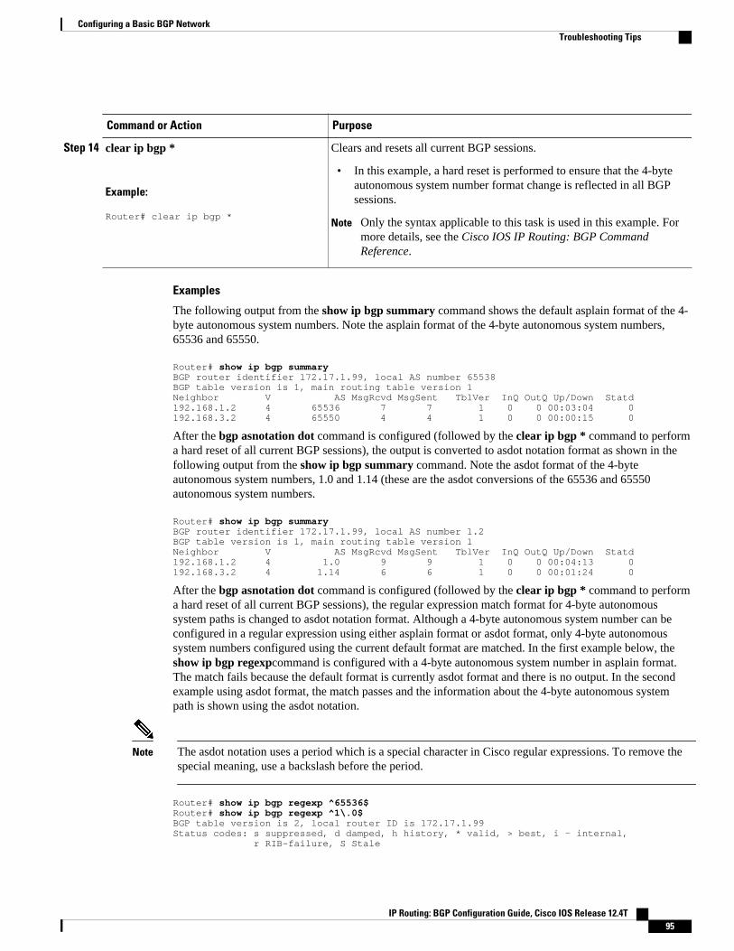
Command or Action Purpose
Step 14 clear ip bgp *
Example:
Router# clear ip bgp *
Clears and resets all current BGP sessions.
• In this example, a hard reset is performed to ensure that the 4-byteautonomous system number format change is reflected in all BGPsessions.
Note Only the syntax applicable to this task is used in this example. Formore details, see the Cisco IOS IP Routing: BGP CommandReference.
Examples
The following output from the show ip bgp summary command shows the default asplain format of the 4-byte autonomous system numbers. Note the asplain format of the 4-byte autonomous system numbers,65536 and 65550.
Router# show ip bgp summaryBGP router identifier 172.17.1.99, local AS number 65538BGP table version is 1, main routing table version 1Neighbor V AS MsgRcvd MsgSent TblVer InQ OutQ Up/Down Statd192.168.1.2 4 65536 7 7 1 0 0 00:03:04 0192.168.3.2 4 65550 4 4 1 0 0 00:00:15 0
After the bgp asnotation dot command is configured (followed by the clear ip bgp * command to performa hard reset of all current BGP sessions), the output is converted to asdot notation format as shown in thefollowing output from the show ip bgp summary command. Note the asdot format of the 4-byteautonomous system numbers, 1.0 and 1.14 (these are the asdot conversions of the 65536 and 65550autonomous system numbers.
Router# show ip bgp summaryBGP router identifier 172.17.1.99, local AS number 1.2BGP table version is 1, main routing table version 1Neighbor V AS MsgRcvd MsgSent TblVer InQ OutQ Up/Down Statd192.168.1.2 4 1.0 9 9 1 0 0 00:04:13 0192.168.3.2 4 1.14 6 6 1 0 0 00:01:24 0
After the bgp asnotation dot command is configured (followed by the clear ip bgp * command to performa hard reset of all current BGP sessions), the regular expression match format for 4-byte autonomoussystem paths is changed to asdot notation format. Although a 4-byte autonomous system number can beconfigured in a regular expression using either asplain format or asdot format, only 4-byte autonomoussystem numbers configured using the current default format are matched. In the first example below, theshow ip bgp regexpcommand is configured with a 4-byte autonomous system number in asplain format.The match fails because the default format is currently asdot format and there is no output. In the secondexample using asdot format, the match passes and the information about the 4-byte autonomous systempath is shown using the asdot notation.
Note The asdot notation uses a period which is a special character in Cisco regular expressions. To remove thespecial meaning, use a backslash before the period.
Router# show ip bgp regexp ^65536$Router# show ip bgp regexp ^1\.0$BGP table version is 2, local router ID is 172.17.1.99Status codes: s suppressed, d damped, h history, * valid, > best, i - internal, r RIB-failure, S Stale
Configuring a Basic BGP NetworkTroubleshooting Tips
IP Routing: BGP Configuration Guide, Cisco IOS Release 12.4T 95

Origin codes: i - IGP, e - EGP, ? - incomplete Network Next Hop Metric LocPrf Weight Path*> 10.1.1.0/24 192.168.1.2 0 0 1.0 i
Configuring a BGP Peer for the IPv4 VRF Address FamilyPerform this optional task to configure BGP between two IPv4 routers (peers) that must exchange IPv4VRF information because they exist in a VPN. The address family configured here is the IPv4 VRF addressfamily and the configuration is done at Router B in the figure below with the neighbor 192.168.3.2 atRouter E in autonomous system 50000. Remember to perform this task for any neighbor routers that are tobe BGP IPv4 VRF address family peers.
This task does not show the complete configuration required for VPN routing. For some complete exampleconfigurations and an example configuration showing how to create a VRF with a route-target that uses a4-byte autonomous system number, see .
Figure 11 BGP Topology for IPv4 VRF Address Family
Before you perform this task, perform the Configuring a BGP Routing Process, page 82 task.
Configuring a BGP Peer for the IPv4 VRF Address Family Troubleshooting Tips
IP Routing: BGP Configuration Guide, Cisco IOS Release 12.4T96

SUMMARY STEPS
1. enable
2. configure terminal
3. ip vrf vrf-name
4. rd route-distinguisher
5. route-target {import | export| both} route-target-ext-community
6. exit
7. router bgp autonomous-system-number
8. address-family ipv4 [unicast | multicast| vrf vrf-name]
9. neighbor ip-address remote-as autonomous-system-number
10. neighbor {ip-address| peer-group-name} maximum-prefix maximum [threshold] [restart restart-interval] [warning-only]
11. neighbor ip-address activate
12. end
DETAILED STEPS
Command or Action Purpose
Step 1 enable
Example:
Router> enable
Enables privileged EXEC mode.
• Enter your password if prompted.
Step 2 configure terminal
Example:
Router# configure terminal
Enters global configuration mode.
Step 3 ip vrf vrf-name
Example:
Router(config)# ip vrf vpn1
Configures a VRF routing table and enters VRF configuration mode.
• Use the vrf-name argument to specify a name to be assigned to the VRF.
Step 4 rd route-distinguisher
Example:
Router(config-vrf)# rd 45000:5
Creates routing and forwarding tables and specifies the default routedistinguisher for a VPN.
• Use the route-distinguisher argument to add an 8-byte value to an IPv4prefix to create a unique VPN IPv4 prefix.
Configuring a Basic BGP NetworkTroubleshooting Tips
IP Routing: BGP Configuration Guide, Cisco IOS Release 12.4T 97

Command or Action Purpose
Step 5 route-target {import | export| both}route-target-ext-community
Example:
Router(config-vrf)# route-target both 45000:100
Creates a route target extended community for a VRF.
• Use the import keyword to import routing information from the targetVPN extended community.
• Use the export keyword to export routing information to the target VPNextended community.
• Use the both keyword to import both import and export routinginformation to the target VPN extended community.
• Use the route-target-ext-community argument to add the route targetextended community attributes to the VRF's list of import, export, orboth (import and export) route target extended communities.
Step 6 exit
Example:
Router(config-vrf)# exit
Exits VRF configuration mode and enters global configuration mode.
Step 7 router bgp autonomous-system-number
Example:
Router(config)# router bgp 45000
Enters router configuration mode for the specified routing process.
Step 8 address-family ipv4 [unicast | multicast|vrf vrf-name]
Example:
Router(config-router)# address-family ipv4 vrf vpn1
Specifies the IPv4 address family and enters address family configurationmode.
• Use the unicast keyword to specify the IPv4 unicast address family. Bydefault, the router is placed in configuration mode for the IPv4 unicastaddress family if the unicast keyword is not specified with the address-family ipv4 command.
• Use the multicast keyword to specify IPv4 multicast address prefixes.• Use the vrf keyword and vrf-name argument to specify the name of the
VRF instance to associate with subsequent IPv4 address familyconfiguration mode commands.
Step 9 neighbor ip-address remote-asautonomous-system-number
Example:
Router(config-router-af)# neighbor 192.168.3.2 remote-as 45000
Adds the IP address of the neighbor in the specified autonomous system tothe IPv4 multiprotocol BGP neighbor table of the local router.
Configuring a Basic BGP Network Troubleshooting Tips
IP Routing: BGP Configuration Guide, Cisco IOS Release 12.4T98

Command or Action Purpose
Step 10 neighbor {ip-address| peer-group-name}maximum-prefix maximum [threshold][restart restart-interval] [warning-only]
Example:
Router(config-router-af)# neighbor 192.168.3.2 maximum-prefix 10000 warning-only
Controls how many prefixes can be received from a neighbor.
• Use the maximum argument to specify the maximum number of prefixesallowed from the specified neighbor. The number of prefixes that can beconfigured is limited only by the available system resources on a router.
• Use the threshold argument to specify an integer representing apercentage of the maximum prefix limit at which the router starts togenerate a warning message.
• Use the warning-only keyword to allow the router to generate a logmessage when the maximum prefix limit is exceeded, instead ofterminating the peering session.
Step 11 neighbor ip-address activate
Example:
Router(config-router-af)# neighbor 192.168.3.2 activate
Enables the neighbor to exchange prefixes for the IPv4 VRF address familywith the local router.
Step 12 end
Example:
Router(config-router-af)# end
Exits address family configuration mode and enters privileged EXEC mode.
• Troubleshooting Tips, page 99
Troubleshooting TipsUse the ping command to verify basic network connectivity between the BGP routers, and use the show ipvrf command to verify that the VRF instance has been created.
Customizing a BGP PeerPerform this task to customize your BGP peers. Although many of the steps in this task are optional, thistask demonstrates how the neighbor and address family configuration command relationships work. Usingthe example of the IPv4 multicast address family, neighbor address family-independent commands areconfigured before the IPv4 multicast address family is configured. Commands that are address family-dependent are then configured and the exit address-family command is shown. An optional step showshow to disable a neighbor.
Customizing a BGP PeerTroubleshooting Tips
IP Routing: BGP Configuration Guide, Cisco IOS Release 12.4T 99
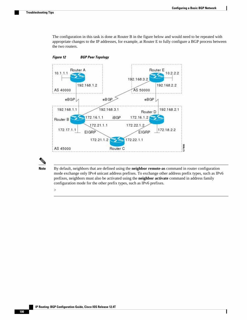
The configuration in this task is done at Router B in the figure below and would need to be repeated withappropriate changes to the IP addresses, for example, at Router E to fully configure a BGP process betweenthe two routers.
Figure 12 BGP Peer Topology
Note By default, neighbors that are defined using the neighbor remote-as command in router configurationmode exchange only IPv4 unicast address prefixes. To exchange other address prefix types, such as IPv6prefixes, neighbors must also be activated using the neighbor activate command in address familyconfiguration mode for the other prefix types, such as IPv6 prefixes.
>
Configuring a Basic BGP Network Troubleshooting Tips
IP Routing: BGP Configuration Guide, Cisco IOS Release 12.4T100

SUMMARY STEPS
1. enable
2. configure terminal
3. router bgp autonomous-system-number
4. no bgp default ipv4-unicast
5. neighbor {ip-address | peer-group-name} remote-as autonomous-system-number
6. neighbor {ip-address | peer-group-name} description text
7. address-family ipv4 [unicast | multicast| vrf vrf-name]
8. network network-number [mask network-mask][route-map route-map-name]
9. neighbor {ip-address | peer-group-name} activate
10. neighbor {ip-address | peer-group-name} advertisement-interval seconds
11. neighbor {ip-address | peer-group-name} default-originate[route-map map-name]
12. exit-address-family
13. neighbor {ip-address | peer-group-name} shutdown
14. end
15. show ip bgp ipv4 multicast [command]
16. show ip bgp neighbors [neighbor-address] [received-routes | routes | advertised-routes | pathsregexp | dampened-routes | received prefix-filter]]
DETAILED STEPS
Command or Action Purpose
Step 1 enable
Example:
Router> enable
Enables privileged EXEC mode.
• Enter your password if prompted.
Step 2 configure terminal
Example:
Router# configure terminal
Enters global configuration mode.
Step 3 router bgp autonomous-system-number
Example:
Router(config)# router bgp 45000
Enters router configuration mode for the specified routing process.
Configuring a Basic BGP NetworkTroubleshooting Tips
IP Routing: BGP Configuration Guide, Cisco IOS Release 12.4T 101

Command or Action Purpose
Step 4 no bgp default ipv4-unicast
Example:
Router(config-router)# no bgp default ipv4-unicast
Disables the IPv4 unicast address family for the BGP routingprocess.
Note Routing information for the IPv4 unicast address family isadvertised by default for each BGP routing sessionconfigured with the neighbor remote-as routerconfiguration command unless you configure the no bgpdefault ipv4-unicastrouter configuration command beforeconfiguring the neighbor remote-as command. Existingneighbor configurations are not affected.
Step 5 neighbor {ip-address | peer-group-name} remote-as autonomous-system-number
Example:
Router(config-router)# neighbor 192.168.3.2 remote-as 50000
Adds the IP address of the neighbor in the specified autonomoussystem to the IPv4 multiprotocol BGP neighbor table of the localrouter.
Step 6 neighbor {ip-address | peer-group-name}description text
Example:
Router(config-router)# neighbor 192.168.3.2 description finance
(Optional) Associates a text description with the specifiedneighbor.
Step 7 address-family ipv4 [unicast | multicast| vrf vrf-name]
Example:
Router(config-router)# address-family ipv4 multicast
Specifies the IPv4 address family and enters address familyconfiguration mode.
• The unicast keyword specifies the IPv4 unicast addressfamily. By default, the router is placed in configuration modefor the IPv4 unicast address family if the unicast keyword isnot specified with the address-family ipv4 command.
• The multicast keyword specifies IPv4 multicast addressprefixes.
• The vrf keyword and vrf-name argument specify the name ofthe VRF instance to associate with subsequent IPv4 addressfamily configuration mode commands.
Step 8 network network-number [mask network-mask][route-map route-map-name]
Example:
Router(config-router-af)# network 172.17.1.0 mask 255.255.255.0
(Optional) Specifies a network as local to this autonomous systemand adds it to the BGP routing table.
• For exterior protocols the network command controls whichnetworks are advertised. Interior protocols use the networkcommand to determine where to send updates.
Configuring a Basic BGP Network Troubleshooting Tips
IP Routing: BGP Configuration Guide, Cisco IOS Release 12.4T102

Command or Action Purpose
Step 9 neighbor {ip-address | peer-group-name} activate
Example:
Router(config-router-af)# neighbor 192.168.3.2 activate
Enables the exchange of information with a BGP neighbor.
Step 10 neighbor {ip-address | peer-group-name}advertisement-interval seconds
Example:
Router(config-router-af)# neighbor 192.168.3.2 advertisement-interval 25
(Optional) Sets the minimum interval between the sending of BGProuting updates.
Step 11 neighbor {ip-address | peer-group-name} default-originate[route-map map-name]
Example:
Router(config-router-af)# neighbor 192.168.3.2 default-originate
(Optional) Permits a BGP speaker--the local router--to send thedefault route 0.0.0.0 to a peer for use as a default route.
Step 12 exit-address-family
Example:
Router(config-router-af)# exit-address-family
Exits address family configuration mode and enters routerconfiguration mode.
Step 13 neighbor {ip-address | peer-group-name}shutdown
Example:
Router(config-router)# neighbor 192.168.3.2 shutdown
(Optional) Disables a BGP peer or peer group.
Note If you perform this step you will not be able to run either ofthe subsequent show command steps because you havedisabled the neighbor.
Step 14 end
Example:
Router(config-router)# end
Exits router configuration mode and enters privileged EXECmode.
Configuring a Basic BGP NetworkTroubleshooting Tips
IP Routing: BGP Configuration Guide, Cisco IOS Release 12.4T 103
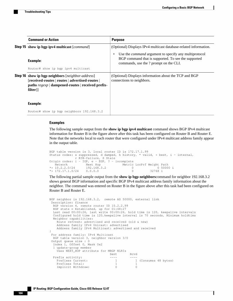
Command or Action Purpose
Step 15 show ip bgp ipv4 multicast [command]
Example:
Router# show ip bgp ipv4 multicast
(Optional) Displays IPv4 multicast database-related information.
• Use the command argument to specify any multiprotocolBGP command that is supported. To see the supportedcommands, use the ? prompt on the CLI.
Step 16 show ip bgp neighbors [neighbor-address][received-routes | routes | advertised-routes |paths regexp | dampened-routes | received prefix-filter]]
Example:
Router# show ip bgp neighbors 192.168.3.2
(Optional) Displays information about the TCP and BGPconnections to neighbors.
Examples
The following sample output from the show ip bgp ipv4 multicast command shows BGP IPv4 multicastinformation for Router B in the figure above after this task has been configured on Router B and Router E.Note that the networks local to each router that were configured under IPv4 multicast address family appearin the output table.
BGP table version is 3, local router ID is 172.17.1.99Status codes: s suppressed, d damped, h history, * valid, > best, i - internal, r RIB-failure, S StaleOrigin codes: i - IGP, e - EGP, ? - incomplete Network Next Hop Metric LocPrf Weight Path*> 10.2.2.0/24 192.168.3.2 0 0 50000 i*> 172.17.1.0/24 0.0.0.0 0 32768 i
The following partial sample output from the show ip bgp neighborscommand for neighbor 192.168.3.2shows general BGP information and specific BGP IPv4 multicast address family information about theneighbor. The command was entered on Router B in the figure above after this task had been configured onRouter B and Router E.
BGP neighbor is 192.168.3.2, remote AS 50000, external link Description: finance BGP version 4, remote router ID 10.2.2.99 BGP state = Established, up for 01:48:27 Last read 00:00:26, last write 00:00:26, hold time is 120, keepalive intervals Configured hold time is 120,keepalive interval is 70 seconds, Minimum holdtims Neighbor capabilities: Route refresh: advertised and received (old & new) Address family IPv4 Unicast: advertised Address family IPv4 Multicast: advertised and received! For address family: IPv4 Multicast BGP table version 3, neighbor version 3/0 Output queue size : 0 Index 1, Offset 0, Mask 0x2 1 update-group member Uses NEXT_HOP attribute for MBGP NLRIs Sent Rcvd Prefix activity: ---- ---- Prefixes Current: 1 1 (Consumes 48 bytes) Prefixes Total: 1 1 Implicit Withdraw: 0 0
Configuring a Basic BGP Network Troubleshooting Tips
IP Routing: BGP Configuration Guide, Cisco IOS Release 12.4T104

Explicit Withdraw: 0 0 Used as bestpath: n/a 1 Used as multipath: n/a 0 Outbound Inbound Local Policy Denied Prefixes: -------- ------- Bestpath from this peer: 1 n/a Total: 1 0 Number of NLRIs in the update sent: max 0, min 0 Minimum time between advertisement runs is 25 seconds Connections established 8; dropped 7 Last reset 01:48:54, due to User resetConnection state is ESTAB, I/O status: 1, unread input bytes: 0 Connection is ECN DisabledLocal host: 192.168.3.1, Local port: 13172Foreign host: 192.168.3.2, Foreign port: 179!
Removing BGP Configuration Commands Using a RedistributionBGP CLI configuration can become quite complex even in smaller BGP networks. If you need to removeany CLI configuration, you must consider all the implications of removing the CLI. Analyze the currentrunning configuration to determine the current BGP neighbor relationships, any address familyconsiderations, and even other routing protocols that are configured. Many BGP CLI commands affectother parts of the CLI configuration.
Perform this task to remove all the BGP configuration commands used in a redistribution of BGP routesinto EIGRP. A route map can be used to match and set parameters or to filter the redistributed routes toensure that routing loops are not created when these routes are subsequently advertised by EIGRP. Whenremoving BGP configuration commands you must remember to remove or disable all the relatedcommands. In this example, if the route-map command is omitted, then the redistribution will still occurand possibly with unexpected results as the route map filtering has been removed. Omitting just theredistribute command would mean that the route map is not applied, but it would leave unused commandsin the running configuration.
For more details on BGP CLI removal, see the "BGP CLI Removal Considerations" concept in the "CiscoBGP Overview" module.
To view the redistribution configuration before and after the CLI removal, see the Examples RemovingBGP Configuration Commands Using a Redistribution Example, page 153.
SUMMARY STEPS
1. enable
2. configure terminal
3. no route-map map-name
4. router eigrp autonomous-system-number
5. no redistribute protocol [as-number]
6. end
7. show running-config
Removing BGP Configuration Commands Using a RedistributionTroubleshooting Tips
IP Routing: BGP Configuration Guide, Cisco IOS Release 12.4T 105
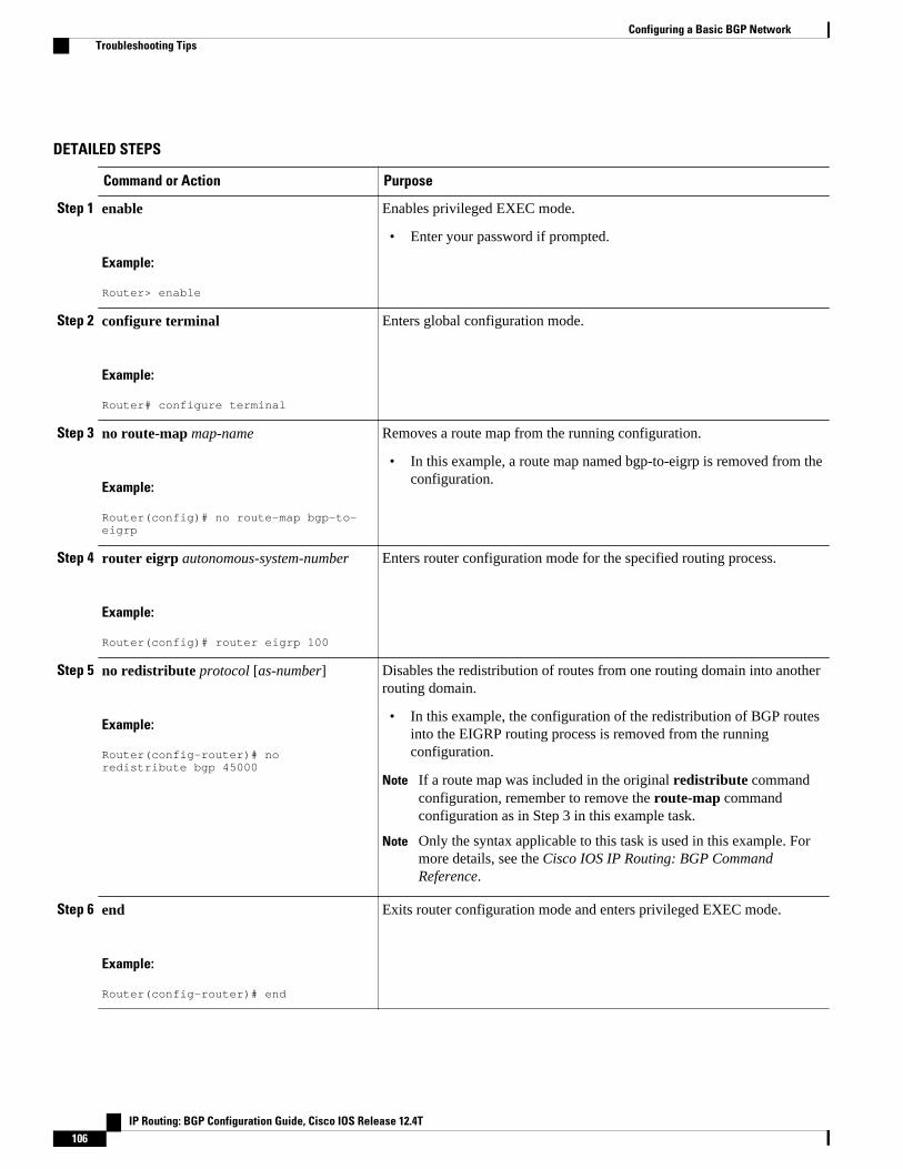
DETAILED STEPS
Command or Action Purpose
Step 1 enable
Example:
Router> enable
Enables privileged EXEC mode.
• Enter your password if prompted.
Step 2 configure terminal
Example:
Router# configure terminal
Enters global configuration mode.
Step 3 no route-map map-name
Example:
Router(config)# no route-map bgp-to-eigrp
Removes a route map from the running configuration.
• In this example, a route map named bgp-to-eigrp is removed from theconfiguration.
Step 4 router eigrp autonomous-system-number
Example:
Router(config)# router eigrp 100
Enters router configuration mode for the specified routing process.
Step 5 no redistribute protocol [as-number]
Example:
Router(config-router)# no redistribute bgp 45000
Disables the redistribution of routes from one routing domain into anotherrouting domain.
• In this example, the configuration of the redistribution of BGP routesinto the EIGRP routing process is removed from the runningconfiguration.
Note If a route map was included in the original redistribute commandconfiguration, remember to remove the route-map commandconfiguration as in Step 3 in this example task.
Note Only the syntax applicable to this task is used in this example. Formore details, see the Cisco IOS IP Routing: BGP CommandReference.
Step 6 end
Example:
Router(config-router)# end
Exits router configuration mode and enters privileged EXEC mode.
Configuring a Basic BGP Network Troubleshooting Tips
IP Routing: BGP Configuration Guide, Cisco IOS Release 12.4T106

Command or Action Purpose
Step 7 show running-config
Example:
Router# show running-config
(Optional) Displays the current running configuration on the router.
• Use this command to verify that the redistribute and route-mapcommands are removed from the router configuration.
Monitoring and Maintaining Basic BGPThe tasks in this section are concerned with the resetting and display of information about basic BGPprocesses and peer relationships. Once you have defined two routers to be BGP neighbors, they will form aBGP connection and exchange routing information. If you subsequently change a BGP filter, weight,distance, version, or timer, or make a similar configuration change, you may have to reset BGP connectionsfor the configuration change to take effect.
• Configuring Inbound Soft-Reconfiguration When Route Refresh Capability Is Missing, page 107
• Resetting and Displaying Basic BGP Information, page 110
Configuring Inbound Soft-Reconfiguration When Route Refresh Capability Is MissingPerform this task to configure inbound soft reconfiguration using the bgp soft-reconfig-backup commandfor BGP peers that do not support the route refresh capability. BGP Peers that support the route refreshcapability are unaffected by the configuration of this command.
SUMMARY STEPS
1. enable
2. configure terminal
3. router bgp autonomous-system-number
4. bgp log-neighbor-changes
5. bgp soft-reconfig-backup
6. neighbor {ip-address | peer-group-name} remote-as autonomous-system-number
7. neighbor {ip-address | peer-group-name} soft-reconfiguration[inbound]
8. neighbor {ip-address | peer-group-name} route-map map-name{in | out}
9. Repeat Steps 6 through 8 for every peer that is to be configured with soft-reconfiguration inbound.
10. exit
11. route-map map-name [permit| deny][sequence-number]
12. set local-preference number-value
13. end
14. show ip bgp neighbors [neighbor-address]
15. show ip bgp [network] [network-mask]
Monitoring and Maintaining Basic BGPConfiguring Inbound Soft-Reconfiguration When Route Refresh Capability Is Missing
IP Routing: BGP Configuration Guide, Cisco IOS Release 12.4T 107

DETAILED STEPS
Command or Action Purpose
Step 1 enable
Example:
Router> enable
Enables privileged EXEC mode.
• Enter your password if prompted.
Step 2 configure terminal
Example:
Router# configure terminal
Enters global configuration mode.
Step 3 router bgp autonomous-system-number
Example:
Router(config)# router bgp 45000
Enters router configuration mode for the specified routingprocess.
Step 4 bgp log-neighbor-changes
Example:
Router(config-router)# bgp log-neighbor-changes
Enables logging of BGP neighbor resets.
Step 5 bgp soft-reconfig-backup
Example:
Router(config-router)# bgp soft-reconfig-backup
Configures a BGP speaker to perform inbound softreconfiguration for peers that do not support the route refreshcapability.
• This command is used to configure BGP to performinbound soft reconfiguration for peers that do not supportthe route refresh capability. The configuration of thiscommand allows you to configure BGP to store updates(soft reconfiguration) only as necessary. Peers that supportthe route refresh capability are unaffected by theconfiguration of this command.
Step 6 neighbor {ip-address | peer-group-name} remote-asautonomous-system-number
Example:
Router(config-router)# neighbor 192.168.1.2 remote-as 40000
Adds the IP address of the neighbor in the specifiedautonomous system to the IPv4 multiprotocol BGP neighbortable of the local router.
Configuring a Basic BGP Network Configuring Inbound Soft-Reconfiguration When Route Refresh Capability Is Missing
IP Routing: BGP Configuration Guide, Cisco IOS Release 12.4T108

Command or Action Purpose
Step 7 neighbor {ip-address | peer-group-name} soft-reconfiguration[inbound]
Example:
Router(config-router)# neighbor 192.168.1.2 soft-reconfiguration inbound
Configures the Cisco IOS software to start storing updates.
• All the updates received from this neighbor will be storedunmodified, regardless of the inbound policy. Wheninbound soft reconfiguration is done later, the storedinformation will be used to generate a new set of inboundupdates.
Step 8 neighbor {ip-address | peer-group-name} route-mapmap-name{in | out}
Example:
Router(config-router)# neighbor 192.168.1.2 route-map LOCAL in
Applies a route map to incoming or outgoing routes.
• In this example, the route map named LOCAL will beapplied to incoming routes.
Step 9 Repeat Steps 6 through 8 for every peer that is to beconfigured with soft-reconfiguration inbound.
--
Step 10 exit
Example:
Router(config-router)# exit
Exits router configuration mode and enters global configurationmode.
Step 11 route-map map-name [permit| deny][sequence-number]
Example:
Router(config)# route-map LOCAL permit 10
Configures a route map and enters route map configurationmode.
• In this example, a route map named LOCAL is created.
Step 12 set local-preference number-value
Example:
Router(config-route-map)# set local-preference 200
Specifies a preference value for the autonomous system path.
• In this example, the local preference value is set to 200.
Step 13 end
Example:
Router(config-route-map)# end
Exits route map configuration mode and enters privilegedEXEC mode.
Configuring a Basic BGP NetworkConfiguring Inbound Soft-Reconfiguration When Route Refresh Capability Is Missing
IP Routing: BGP Configuration Guide, Cisco IOS Release 12.4T 109

Command or Action Purpose
Step 14 show ip bgp neighbors [neighbor-address]
Example:
Router(config-router-af)# show ip bgp neighbors 192.168.1.2
(Optional) Displays information about the TCP and BGPconnections to neighbors.
Note Only the syntax applicable to this task is used in thisexample. For more details, see the Cisco IOS IP Routing:BGP Command Reference.
Step 15 show ip bgp [network] [network-mask]
Example:
Router# show ip bgp
(Optional) Displays the entries in the BGP routing table.
Note Only the syntax applicable to this task is used in thisexample. For more details, see the Cisco IOS IP Routing:BGP Command Reference.
Examples
The following partial output from the show ip bgp neighbors command shows information about the TCPand BGP connections to the BGP neighbor 192.168.2.1. This peer supports route refresh.
BGP neighbor is 192.168.1.2, remote AS 40000, external link Neighbor capabilities: Route refresh: advertised and received(new)
The following partial output from the show ip bgp neighbors command shows information about the TCPand BGP connections to the BGP neighbor 192.168.3.2. This peer does not support route refresh so thesoft-reconfig inbound paths for BGP peer 192.168.3.2 will be stored because there is no other way toupdate any inbound policy updates.
BGP neighbor is 192.168.3.2, remote AS 50000, external link Neighbor capabilities: Route refresh: advertised
The following sample output from the show ip bgp command shows the entry for the network 172.17.1.0.Both BGP peers are advertising 172.17.1.0/24 but only the received-only path is stored for 192.168.3.2.
BGP routing table entry for 172.17.1.0/24, version 11Paths: (3 available, best #3, table Default-IP-Routing-Table, RIB-failure(4))Flag: 0x820 Advertised to update-groups: 1 50000 192.168.3.2 from 192.168.3.2 (172.17.1.0) Origin incomplete, metric 0, localpref 200, valid, external 50000, (received-only) 192.168.3.2 from 192.168.3.2 (172.17.1.0) Origin incomplete, metric 0, localpref 100, valid, external 40000 192.168.1.2 from 192.168.1.2 (172.16.1.0) Origin incomplete, metric 0, localpref 200, valid, external, best
Resetting and Displaying Basic BGP InformationPerform this task to reset and display information about basic BGP processes and peer relationships.
Configuring a Basic BGP Network Resetting and Displaying Basic BGP Information
IP Routing: BGP Configuration Guide, Cisco IOS Release 12.4T110

SUMMARY STEPS
1. enable
2. clear ip bgp {* | autonomous-system-number | neighbor-address}} [soft [in | out]
3. show ip bgp [network-address][network-mask] [longer-prefixes] [prefix-list prefix-list-name | route-map route-map-name] [shorter prefixes mask-length]
4. show ip bgp neighbors [neighbor-address] [received-routes | routes | advertised-routes | pathsregexp | dampened-routes | received prefix-filter]]
5. show ip bgp paths
6. show ip bgp summary
DETAILED STEPS
Command or Action Purpose
Step 1 enable
Example:
Router> enable
Enables privileged EXEC mode.
• Enter your password if prompted.
Step 2 clear ip bgp {* | autonomous-system-number | neighbor-address}} [soft [in | out]
Example:
Router# clear ip bgp *
Clears and resets BGP neighbor sessions:
• In the example provided, all BGP neighbor sessionsare cleared and reset.
Step 3 show ip bgp [network-address][network-mask] [longer-prefixes] [prefix-list prefix-list-name | route-map route-map-name] [shorter prefixes mask-length]
Example:
Router# show ip bgp 10.1.1.0 255.255.255.0
Displays all the entries in the BGP routing table:
• In the example provided, the BGP routing tableinformation for the 10.1.1.0 network is displayed.
Step 4 show ip bgp neighbors [neighbor-address] [received-routes |routes | advertised-routes | paths regexp | dampened-routes |received prefix-filter]]
Example:
Router# show ip bgp neighbors 192.168.3.2 advertised-routes
Displays information about the TCP and BGPconnections to neighbors.
• In the example provided, the routes advertised fromthe router to BGP neighbor 192.168.3.2 on anotherrouter are displayed.
Configuring a Basic BGP NetworkResetting and Displaying Basic BGP Information
IP Routing: BGP Configuration Guide, Cisco IOS Release 12.4T 111
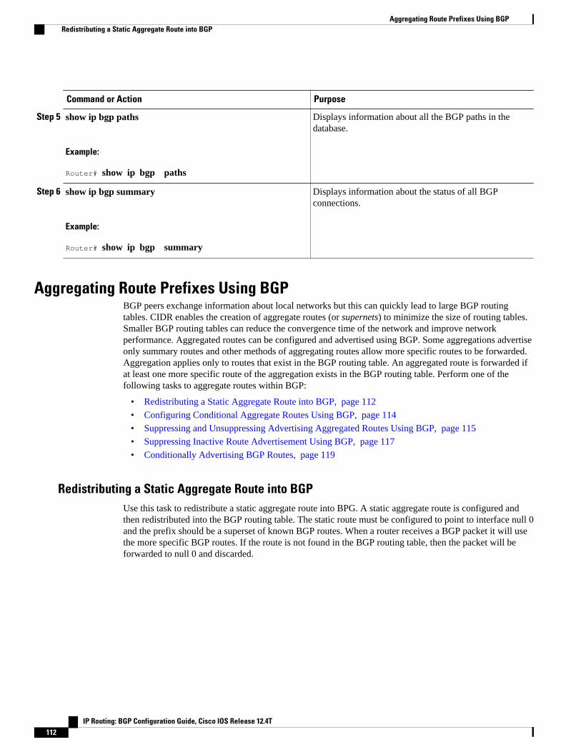
Command or Action Purpose
Step 5 show ip bgp paths
Example:
Router# show ip bgp paths
Displays information about all the BGP paths in thedatabase.
Step 6 show ip bgp summary
Example:
Router# show ip bgp summary
Displays information about the status of all BGPconnections.
Aggregating Route Prefixes Using BGPBGP peers exchange information about local networks but this can quickly lead to large BGP routingtables. CIDR enables the creation of aggregate routes (or supernets) to minimize the size of routing tables.Smaller BGP routing tables can reduce the convergence time of the network and improve networkperformance. Aggregated routes can be configured and advertised using BGP. Some aggregations advertiseonly summary routes and other methods of aggregating routes allow more specific routes to be forwarded.Aggregation applies only to routes that exist in the BGP routing table. An aggregated route is forwarded ifat least one more specific route of the aggregation exists in the BGP routing table. Perform one of thefollowing tasks to aggregate routes within BGP:
• Redistributing a Static Aggregate Route into BGP, page 112
• Configuring Conditional Aggregate Routes Using BGP, page 114
• Suppressing and Unsuppressing Advertising Aggregated Routes Using BGP, page 115
• Suppressing Inactive Route Advertisement Using BGP, page 117
• Conditionally Advertising BGP Routes, page 119
Redistributing a Static Aggregate Route into BGPUse this task to redistribute a static aggregate route into BPG. A static aggregate route is configured andthen redistributed into the BGP routing table. The static route must be configured to point to interface null 0and the prefix should be a superset of known BGP routes. When a router receives a BGP packet it will usethe more specific BGP routes. If the route is not found in the BGP routing table, then the packet will beforwarded to null 0 and discarded.
Aggregating Route Prefixes Using BGP Redistributing a Static Aggregate Route into BGP
IP Routing: BGP Configuration Guide, Cisco IOS Release 12.4T112

SUMMARY STEPS
1. enable
2. configure terminal
3. ip route prefix mask {ip-address | interface-type interface-number [ip-address]} [distance] [name][permanent | track number] [tag tag]
4. router bgp autonomous-system-number
5. redistribute static
6. end
DETAILED STEPS
Command or Action Purpose
Step 1 enable
Example:
Router> enable
Enables privileged EXEC mode.
• Enter your password if prompted.
Step 2 configure terminal
Example:
Router# configure terminal
Enters global configuration mode.
Step 3 ip route prefix mask {ip-address | interface-type interface-number [ip-address]} [distance] [name] [permanent | track number] [tag tag]
Example:
Router(config)# ip route 172.0.0.0 255.0.0.0 null 0
Creates a static route.
Step 4 router bgp autonomous-system-number
Example:
Router(config)# router bgp 45000
Enters router configuration mode for thespecified routing process.
Step 5 redistribute static
Example:
Router(config-router)# redistribute static
Redistributes routes into the BGP routing table.
Configuring a Basic BGP NetworkRedistributing a Static Aggregate Route into BGP
IP Routing: BGP Configuration Guide, Cisco IOS Release 12.4T 113

Command or Action Purpose
Step 6 end
Example:
Router(config-router)# end
Exits router configuration mode and returns toprivileged EXEC mode.
Configuring Conditional Aggregate Routes Using BGPUse this task to create an aggregate route entry in the BGP routing table when at least one specific routefalls into the specified range. The aggregate route is advertised as originating from your autonomoussystem. For more information, see the BGP Aggregation Route AS-SET Information Generation, page 73.
SUMMARY STEPS
1. enable
2. configure terminal
3. router bgp autonomous-system-number
4. aggregate-address address mask [as-set]
5. end
DETAILED STEPS
Command or Action Purpose
Step 1 enable
Example:
Router> enable
Enables privileged EXEC mode.
• Enter your password if prompted.
Step 2 configure terminal
Example:
Router# configure terminal
Enters global configuration mode.
Step 3 router bgp autonomous-system-number
Example:
Router(config)# router bgp 45000
Enters router configuration mode for the specified routing process.
Configuring a Basic BGP Network Configuring Conditional Aggregate Routes Using BGP
IP Routing: BGP Configuration Guide, Cisco IOS Release 12.4T114

Command or Action Purpose
Step 4 aggregate-address address mask [as-set]
Example:
Router(config-router)# aggregate-address 172.0.0.0 255.0.0.0 as-set
Creates an aggregate entry in a BGP routing table.
• A specified route must exist in the BGP table.• Use the aggregate-address command with no keywords to create an
aggregate entry if any more-specific BGP routes are available that fall inthe specified range.
• Use the as-set keyword to specify that the path advertised for this route isan AS-SET. Do not use the as-set keyword when aggregating manypaths because this route is withdrawn and updated every time thereachability information for the aggregated route changes.
Note Only partial syntax is used in this example. For more details, see theCisco IOS IP Routing: BGP Command Reference.
Step 5 end
Example:
Router(config-router)# end
Exits router configuration mode and enters privileged EXEC mode.
Suppressing and Unsuppressing Advertising Aggregated Routes Using BGPUse this task to create an aggregate route, suppress the advertisement of routes using BGP, andsubsequently unsuppress the advertisement of routes. Routes that are suppressed are not advertised to anyneighbors, but it is possible to unsuppress routes that were previously suppressed to specific neighbors.
SUMMARY STEPS
1. enable
2. configure terminal
3. router bgp autonomous-system-number
4. neighbor ip-address remote-as autonomous-system-number
5. Do one of the following:
• aggregate-address address mask [summary-only]•• aggregate-address address mask [suppress-map map-name]
6. neighbor {ip-address | peer-group-name} unsuppress-map map-name
7. end
Configuring a Basic BGP NetworkSuppressing and Unsuppressing Advertising Aggregated Routes Using BGP
IP Routing: BGP Configuration Guide, Cisco IOS Release 12.4T 115

DETAILED STEPS
Command or Action Purpose
Step 1 enable
Example:
Router> enable
Enables privileged EXEC mode.
• Enter your password if prompted.
Step 2 configure terminal
Example:
Router# configure terminal
Enters global configuration mode.
Step 3 router bgp autonomous-system-number
Example:
Router(config)# router bgp 45000
Enters router configuration mode for the specified routing process.
Step 4 neighbor ip-address remote-as autonomous-system-number
Example:
Router(config-router)# neighbor 192.168.1.2 remote-as 40000
Adds the IP address of the neighbor in the specified autonomoussystem to the IPv4 multiprotocol BGP neighbor table of the localrouter.
Step 5 Do one of the following:
• aggregate-address address mask[summary-only]
•• aggregate-address address mask [suppress-
map map-name]
Example:
Router(config-router)# aggregate-address 172.0.0.0 255.0.0.0 summary-only
Example:
Router(config-router)# aggregate-address 172.0.0.0 255.0.0.0 suppress-map map1
Creates an aggregate route.
• Use the optional summary-only keyword to create the aggregateroute (for example, 10.*.*.*) and also suppresses advertisementsof more-specific routes to all neighbors.
• Use the optional suppress-mapkeyword to create the aggregateroute but suppress advertisement of specified routes. Routes thatare suppressed are not advertised to any neighbors. You can usethe match clauses of route maps to selectively suppress somemore-specific routes of the aggregate and leave othersunsuppressed. IP access lists and autonomous system path accesslists match clauses are supported.
Note Only partial syntax is used in this example. For more details,see the Cisco IOS IP Routing: BGP Command Reference.
Configuring a Basic BGP Network Suppressing and Unsuppressing Advertising Aggregated Routes Using BGP
IP Routing: BGP Configuration Guide, Cisco IOS Release 12.4T116

Command or Action Purpose
Step 6 neighbor {ip-address | peer-group-name}unsuppress-map map-name
Example:
Router(config-router)# neighbor 192.168.1.2 unsuppress map1
(Optional) Selectively advertises routes previously suppressed by theaggregate-address command.
• In this example, the routes previously suppressed in Step 5 areadvertised to neighbor 192.168.1.2.
Step 7 end
Example:
Router(config-router)# end
Exits router configuration mode and enters privileged EXEC mode.
Suppressing Inactive Route Advertisement Using BGPPerform this task to suppress the advertisement of inactive routes by BGP. In Cisco IOS Release 12.2(25)S,12.2(33)SXH, and 15.0(1)M, the bgp suppress-inactive command was introduced to configure BGP to notadvertise inactive routes to any BGP peer. A BGP routing process can advertise routes that are not installedin the RIB to BGP peers by default. A route that is not installed into the RIB is an inactive route. Inactiveroute advertisement can occur, for example, when routes are advertised through common route aggregation.
Inactive route advertisements can be suppressed to provide more consistent data forwarding. This featurecan be configured on a per IPv4 address family basis. For example, when specifying the maximum numberof routes that can be configured in a VRF with the maximum routes global configuration command, youalso suppress inactive route advertisement to prevent inactive routes from being accepted into the VRFafter route limit has been exceeded.
This task assumes that BGP is enabled and that peering has been established.
Note Inactive route suppression can be configured only under the IPv4 address family or under a default IPv4general session.
>
SUMMARY STEPS
1. enable
2. configure terminal
3. router bgp as-number
4. address-family {ipv4 [mdt | multicast | unicast [vrf vrf-name] | vrf vrf-name] | vpnv4 [unicast]}
5. bgp suppress-inactive
6. end
7. show ip bgp rib-failure
Configuring a Basic BGP NetworkSuppressing Inactive Route Advertisement Using BGP
IP Routing: BGP Configuration Guide, Cisco IOS Release 12.4T 117

DETAILED STEPS
Command or Action Purpose
Step 1 enable
Example:
Router> enable
Enables privileged EXEC mode.
• Enter your password if prompted.
Step 2 configure terminal
Example:
Router# configure terminal
Enters global configuration mode.
Step 3 router bgp as-number
Example:
Router(config)# router bgp 45000
Enters router configuration mode and creates a BGP routingprocess.
Step 4 address-family {ipv4 [mdt | multicast | unicast [vrf vrf-name] | vrf vrf-name] | vpnv4 [unicast]}
Example:
Router(config-router)# address-family ipv4 unicast
Enter address family configuration mode to configure BGPpeers to accept address family specific configurations.
• The example creates an IPv4 unicast address familysession.
Step 5 bgp suppress-inactive
Example:
Router(config-router-af)# bgp suppress-inactive
Suppresses BGP advertising of inactive routes.
• BGP advertises inactive routes by default.• Entering the no form of this command reenables the
advertisement of inactive routes.
Step 6 end
Example:
Router(config-router-af)# end
Exits address family configuration mode and enters privilegedEXEC mode.
Step 7 show ip bgp rib-failure
Example:
Router# show ip bgp rib-failure
(Optional) Displays BGP routes that are not installed in theRIB.
Configuring a Basic BGP Network Suppressing Inactive Route Advertisement Using BGP
IP Routing: BGP Configuration Guide, Cisco IOS Release 12.4T118

Examples
The following example shows output from the show ip bgp rib-failure command displaying routes that arenot installed in the RIB. The output shows that the displayed routes were not installed because a route orroutes with a better administrative distance already exist in the RIB.
Router# show ip bgp rib-failure Network Next Hop RIB-failure RIB-NH Matches10.1.15.0/24 10.1.35.5 Higher admin distance n/a10.1.16.0/24 10.1.15.1 Higher admin distance n/a
Conditionally Advertising BGP RoutesPerform this task to conditionally advertise selected BGP routes. The routes or prefixes that will beconditionally advertised are defined in two route maps: an advertise map and either an exist map ornonexist map. The route map associated with the exist map or nonexist map specifies the prefix that theBGP speaker will track. The route map associated with the advertise map specifies the prefix that will beadvertised to the specified neighbor when the condition is met.
• If a prefix is found to be present in the exist map by the BGP speaker, then the prefix specified by theadvertise map is advertised.
• If a prefix is found not to be present in the nonexist map by the BGP speaker, then the prefix specifiedby the advertise map is advertised.
If the condition is not met, the route is withdrawn and conditional advertisement does not occur. All routesthat may be dynamically advertised or not advertised need to exist in the BGP routing table for conditionaladvertisement to occur. These routes are referenced from an access list or an IP prefix list.
SUMMARY STEPS
1. enable
2. configure terminal
3. router bgp autonomous-system-number
4. neighbor {ip-address | peer-group-name} remote-as autonomous-system-number
5. neighbor ip-address advertise-map map-name {exist-map map-name | non-exist-map map-name}
6. exit
7. route-map map-tag [permit| deny][sequence-number]
8. match ip address {access-list-number [access-list-number... | access-list-name...] | access-list-name[access-list-number...| access-list-name] | prefix-list prefix-list-name [prefix-list-name...]}
9. route-map map-tag [permit| deny][sequence-number]
10. match ip address {access-list-number [access-list-number... | access-list-name...] | access-list-name[access-list-number...| access-list-name] | prefix-list prefix-list-name [prefix-list-name...]}
11. exit
12. access-list access-list-number {deny | permit} source [source-wildcard] [log]
13. access-list access-list-number {deny | permit} source [source-wildcard] [log]
14. exit
Configuring a Basic BGP NetworkConditionally Advertising BGP Routes
IP Routing: BGP Configuration Guide, Cisco IOS Release 12.4T 119
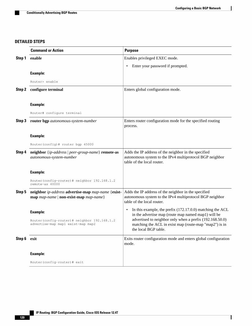
DETAILED STEPS
Command or Action Purpose
Step 1 enable
Example:
Router> enable
Enables privileged EXEC mode.
• Enter your password if prompted.
Step 2 configure terminal
Example:
Router# configure terminal
Enters global configuration mode.
Step 3 router bgp autonomous-system-number
Example:
Router(config)# router bgp 45000
Enters router configuration mode for the specified routingprocess.
Step 4 neighbor {ip-address | peer-group-name} remote-asautonomous-system-number
Example:
Router(config-router)# neighbor 192.168.1.2 remote-as 40000
Adds the IP address of the neighbor in the specifiedautonomous system to the IPv4 multiprotocol BGP neighbortable of the local router.
Step 5 neighbor ip-address advertise-map map-name {exist-map map-name | non-exist-map map-name}
Example:
Router(config-router)# neighbor 192.168.1.2 advertise-map map1 exist-map map2
Adds the IP address of the neighbor in the specifiedautonomous system to the IPv4 multiprotocol BGP neighbortable of the local router.
• In this example, the prefix (172.17.0.0) matching the ACLin the advertise map (route map named map1) will beadvertised to neighbor only when a prefix (192.168.50.0)matching the ACL in exist map (route-map "map2") is inthe local BGP table.
Step 6 exit
Example:
Router(config-router)# exit
Exits router configuration mode and enters global configurationmode.
Configuring a Basic BGP Network Conditionally Advertising BGP Routes
IP Routing: BGP Configuration Guide, Cisco IOS Release 12.4T120

Command or Action Purpose
Step 7 route-map map-tag [permit| deny][sequence-number]
Example:
Router(config)# route-map map1 permit 10
Configures a route map and enters route map configurationmode.
• In this example, a route map named map1 is created.
Step 8 match ip address {access-list-number [access-list-number... | access-list-name...] | access-list-name[access-list-number...| access-list-name] | prefix-listprefix-list-name [prefix-list-name...]}
Example:
Router(config-route-map)# match ip address 1
Configures the route map to match a prefix that is permitted bya standard access list, an extended access list, or a prefix list.
• In this example, the route map is configured to match aprefix permitted by access list 1.
Step 9 route-map map-tag [permit| deny][sequence-number]
Example:
Router(config)# route-map map2 permit 10
Configures a route map and enters route map configurationmode.
• In this example, a route map named map2 is created.
Step 10 match ip address {access-list-number [access-list-number... | access-list-name...] | access-list-name[access-list-number...| access-list-name] | prefix-listprefix-list-name [prefix-list-name...]}
Example:
Router(config-route-map)# match ip address 2
Configures the route map to match a prefix that is permitted bya standard access list, an extended access list, or a prefix list.
• In this example, the route map is configured to match aprefix permitted by access list 2.
Step 11 exit
Example:
Router(config-route-map)# exit
Exits route map configuration mode and enters globalconfiguration mode.
Step 12 access-list access-list-number {deny | permit} source[source-wildcard] [log]
Example:
Router(config)# access-list 1 permit 172.17.0.0
Configures a standard access list.
• In this example, access list 1 permits advertising of the172.17.0.0 prefix, depending on other conditions set by theneighbor advertise-map command.
Configuring a Basic BGP NetworkConditionally Advertising BGP Routes
IP Routing: BGP Configuration Guide, Cisco IOS Release 12.4T 121
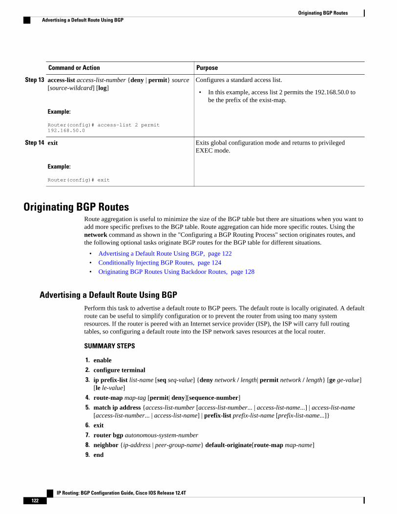
Command or Action Purpose
Step 13 access-list access-list-number {deny | permit} source[source-wildcard] [log]
Example:
Router(config)# access-list 2 permit 192.168.50.0
Configures a standard access list.
• In this example, access list 2 permits the 192.168.50.0 tobe the prefix of the exist-map.
Step 14 exit
Example:
Router(config)# exit
Exits global configuration mode and returns to privilegedEXEC mode.
Originating BGP RoutesRoute aggregation is useful to minimize the size of the BGP table but there are situations when you want toadd more specific prefixes to the BGP table. Route aggregation can hide more specific routes. Using thenetwork command as shown in the "Configuring a BGP Routing Process" section originates routes, andthe following optional tasks originate BGP routes for the BGP table for different situations.
• Advertising a Default Route Using BGP, page 122
• Conditionally Injecting BGP Routes, page 124
• Originating BGP Routes Using Backdoor Routes, page 128
Advertising a Default Route Using BGPPerform this task to advertise a default route to BGP peers. The default route is locally originated. A defaultroute can be useful to simplify configuration or to prevent the router from using too many systemresources. If the router is peered with an Internet service provider (ISP), the ISP will carry full routingtables, so configuring a default route into the ISP network saves resources at the local router.
SUMMARY STEPS
1. enable
2. configure terminal
3. ip prefix-list list-name [seq seq-value] {deny network / length| permit network / length} [ge ge-value][le le-value]
4. route-map map-tag [permit| deny][sequence-number]
5. match ip address {access-list-number [access-list-number... | access-list-name...] | access-list-name[access-list-number... | access-list-name] | prefix-list prefix-list-name [prefix-list-name...]}
6. exit
7. router bgp autonomous-system-number
8. neighbor {ip-address | peer-group-name} default-originate[route-map map-name]
9. end
Originating BGP Routes Advertising a Default Route Using BGP
IP Routing: BGP Configuration Guide, Cisco IOS Release 12.4T122

DETAILED STEPS
Command or Action Purpose
Step 1 enable
Example:
Router> enable
Enables privileged EXEC mode.
• Enter your password if prompted.
Step 2 configure terminal
Example:
Router# configure terminal
Enters global configuration mode.
Step 3 ip prefix-list list-name [seq seq-value] {deny network /length| permit network / length} [ge ge-value] [le le-value]
Example:
Router(config)# ip prefix-list DEFAULT permit 10.1.1.0/24
Configures an IP prefix list.
• In this example, prefix list DEFAULT permitsadvertising of the 10.1.1.0/24. prefix depending on amatch set by the match ip address command.
Step 4 route-map map-tag [permit| deny][sequence-number]
Example:
Router(config)# route-map ROUTE
Configures a route map and enters route map configurationmode.
• In this example, a route map named ROUTE iscreated.
Step 5 match ip address {access-list-number [access-list-number...| access-list-name...] | access-list-name [access-list-number...| access-list-name] | prefix-list prefix-list-name [prefix-list-name...]}
Example:
Router(config-route-map)# match ip address prefix-list DEFAULT
Configures the route map to match a prefix that ispermitted by a standard access list, an extended access list,or a prefix list.
• In this example, the route map is configured to matcha prefix permitted by prefix list DEFAULT.
Step 6 exit
Example:
Router(config-route-map)# exit
Exits route map configuration mode and enters globalconfiguration mode.
Configuring a Basic BGP NetworkAdvertising a Default Route Using BGP
IP Routing: BGP Configuration Guide, Cisco IOS Release 12.4T 123

Command or Action Purpose
Step 7 router bgp autonomous-system-number
Example:
Router(config)# router bgp 40000
Enters router configuration mode for the specified routingprocess.
Step 8 neighbor {ip-address | peer-group-name} default-originate[route-map map-name]
Example:
Router(config-router)# neighbor 192.168.3.2 default-originate
(Optional) Permits a BGP speaker--the local router--to sendthe default route 0.0.0.0 to a peer for use as a default route.
Step 9 end
Example:
Router(config-router)# end
Exits router configuration mode and enters privilegedEXEC mode.
• Troubleshooting Tips, page 124
Troubleshooting Tips
Use the show ip route command on the receiving BGP peer (not on the local router) to verify that thedefault route has been set. In the output, verify that a line similar to the following showing the default route0.0.0.0 is present:
B* 0.0.0.0/0 [20/0] via 192.168.1.2, 00:03:10
Conditionally Injecting BGP RoutesUse this task to inject more specific prefixes into a BGP routing table over less specific prefixes that wereselected through normal route aggregation. These more specific prefixes can be used to provide a finergranularity of traffic engineering or administrative control than is possible with aggregated routes. Formore information, see the "Conditional BGP Route Injection" section.
This task assumes that the IGP is already configured for the BGP peers.
Configuring a Basic BGP Network Troubleshooting Tips
IP Routing: BGP Configuration Guide, Cisco IOS Release 12.4T124

SUMMARY STEPS
1. enable
2. configure terminal
3. router bgp autonomous-system-number
4. bgp inject-map inject-map-name exist-map exist-map-name [copy-attributes]
5. exit
6. route-map map-tag [permit| deny][sequence-number]
7. match ip address {access-list-number [access-list-number... | access-list-name...] | access-list-name[access-list-number... | access-list-name] | prefix-list prefix-list-name [prefix-list-name...]}
8. match ip route-source {access-list-number | access-list-name} [access-list-number...| access-list-name...]
9. exit
10. route-map map-tag [permit| deny][sequence-number]
11. set ip address {access-list-number [access-list-number... | access-list-name...] | access-list-name[access-list-number... | access-list-name] | prefix-list prefix-list-name [prefix-list-name...]}
12. set community {community-number [additive] [well-known-community] | none}
13. exit
14. ip prefix-list list-name [seq seq-value] {deny network / length | permit network / length} [ge ge-value][le le-value]
15. Repeat Step 14 for every prefix list to be created.
16. exit
17. show ip bgp injected-paths
DETAILED STEPS
Command or Action Purpose
Step 1 enable
Example:
Router> enable
Enables privileged EXEC mode.
• Enter your password if prompted.
Step 2 configure terminal
Example:
Router# configure terminal
Enters global configuration mode.
Step 3 router bgp autonomous-system-number
Example:
Router(config)# router bgp 40000
Enters router configuration mode for the specified routingprocess.
Configuring a Basic BGP NetworkConditionally Injecting BGP Routes
IP Routing: BGP Configuration Guide, Cisco IOS Release 12.4T 125

Command or Action Purpose
Step 4 bgp inject-map inject-map-name exist-map exist-map-name [copy-attributes]
Example:
Router(config-router)# bgp inject-map ORIGINATE exist-map LEARNED_PATH
Specifies the inject map and the exist map for conditionalroute injection.
• Use the copy-attributes keyword to specify that theinjected route inherit the attributes of the aggregateroute.
Step 5 exit
Example:
Router(config-router)# exit
Exits router configuration mode and enters globalconfiguration mode.
Step 6 route-map map-tag [permit| deny][sequence-number]
Example:
Router(config)# route-map LEARNED_PATH permit 10
Configures a route map and enters route mapconfiguration mode.
Step 7 match ip address {access-list-number [access-list-number... | access-list-name...] | access-list-name [access-list-number... | access-list-name] | prefix-list prefix-list-name [prefix-list-name...]}
Example:
Router(config-route-map)# match ip address prefix-list SOURCE
Specifies the aggregate route to which a more specificroute will be injected.
• In this example, the prefix list named SOURCE isused to redistribute the source of the route.
Step 8 match ip route-source {access-list-number | access-list-name} [access-list-number...| access-list-name...]
Example:
Router(config-route-map)# match ip route-source prefix-list ROUTE_SOURCE
Specifies the match conditions for redistributing thesource of the route.
• In this example, the prefix list namedROUTE_SOURCE is used to redistribute the sourceof the route.
Note The route source is the neighbor address that isconfigured with the neighbor remote-as command.The tracked prefix must come from this neighbor inorder for conditional route injection to occur.
Step 9 exit
Example:
Router(config-route-map)# exit
Exits route map configuration mode and enters globalconfiguration mode.
Configuring a Basic BGP Network Conditionally Injecting BGP Routes
IP Routing: BGP Configuration Guide, Cisco IOS Release 12.4T126

Command or Action Purpose
Step 10 route-map map-tag [permit| deny][sequence-number]
Example:
Router(config)# route-map ORIGINATE permit 10
Configures a route map and enters route mapconfiguration mode.
Step 11 set ip address {access-list-number [access-list-number... |access-list-name...] | access-list-name [access-list-number... |access-list-name] | prefix-list prefix-list-name [prefix-list-name...]}
Example:
Router(config-route-map)# set ip address prefix-list ORIGINATED_ROUTES
Specifies the routes to be injected.
• In this example, the prefix list namedoriginated_routes is used to redistribute the source ofthe route.
Step 12 set community {community-number [additive] [well-known-community] | none}
Example:
Router(config-route-map)# set community 14616:555 additive
Sets the BGP community attribute of the injected route.
Step 13 exit
Example:
Router(config-route-map)# exit
Exits route map configuration mode and enters globalconfiguration mode.
Step 14 ip prefix-list list-name [seq seq-value] {deny network /length | permit network / length} [ge ge-value] [le le-value]
Example:
Router(config)# ip prefix-list SOURCE permit 10.1.1.0/24
Configures a prefix list.
• In this example, the prefix list named SOURCE isconfigured to permit routes from network 10.1.1.0/24.
Step 15 Repeat Step 14 for every prefix list to be created. --
Step 16 exit
Example:
Router(config)# exit
Exits global configuration mode and returns to privilegedEXEC mode.
Configuring a Basic BGP NetworkConditionally Injecting BGP Routes
IP Routing: BGP Configuration Guide, Cisco IOS Release 12.4T 127

Command or Action Purpose
Step 17 show ip bgp injected-paths
Example:
Router# show ip bgp injected-paths
(Optional) Displays information about injected paths.
Examples
The following sample output is similar to the output that will be displayed when the show ip bgp injected-pathscommand is entered:
Router# show ip bgp injected-pathsBGP table version is 11, local router ID is 10.0.0.1Status codes:s suppressed, d damped, h history, * valid, > best, i -internalOrigin codes:i - IGP, e - EGP, ? - incomplete Network Next Hop Metric LocPrf Weight Path*> 172.16.0.0 10.0.0.2 0 ?*> 172.17.0.0/16 10.0.0.2 0 ?
• Troubleshooting Tips, page 128
Troubleshooting Tips
BGP conditional route injection is based on the injection of a more specific prefix into the BGP routingtable when a less specific prefix is present. If conditional route injection is not working properly, verify thefollowing:
• If conditional route injection is configured but does not occur, verify the existence of the aggregateprefix in the BGP routing table. The existence (or not) of the tracked prefix in the BGP routing tablecan be verified with the show ip bgpcommand.
• If the aggregate prefix exists but conditional route injection does not occur, verify that the aggregateprefix is being received from the correct neighbor and the prefix list identifying that neighbor is a /32match.
• Verify the injection (or not) of the more specific prefix using the show ip bgp injected-pathscommand.
• Verify that the prefix that is being injected is not outside of the scope of the aggregate prefix.• Ensure that the inject route map is configured with the set ip address command and not the match ip
address command.
Originating BGP Routes Using Backdoor RoutesUse this task to indicate to border routers which networks are reachable using a backdoor route. Abackdoor network is treated the same as a local network except that it is not advertised. For moreinformation see the BGP Backdoor Routes, page 76.
This task assumes that the IGP--EIGRP in this example--is already configured for the BGP peers. Theconfiguration is done at Router B in the figure above (in the "BGP Backdoor Routes" section) and the BGPpeer is Router D.
Configuring a Basic BGP Network Troubleshooting Tips
IP Routing: BGP Configuration Guide, Cisco IOS Release 12.4T128

SUMMARY STEPS
1. enable
2. configure terminal
3. router bgp autonomous-system-number
4. neighbor ip-address remote-as autonomous-system-number
5. network ip-address backdoor
6. end
DETAILED STEPS
Command or Action Purpose
Step 1 enable
Example:
Router> enable
Enables privileged EXEC mode.
• Enter your password if prompted.
Step 2 configure terminal
Example:
Router# configure terminal
Enters global configuration mode.
Step 3 router bgp autonomous-system-number
Example:
Router(config)# router bgp 45000
Enters router configuration mode for the specified routing process.
Step 4 neighbor ip-address remote-as autonomous-system-number
Example:
Router(config-router)# neighbor 172.22.1.2 remote-as 45000
Adds the IP address of the neighbor in the specified autonomoussystem to the multiprotocol BGP neighbor table of the localrouter.
• In this example, the peer is an internal peer as theautonomous system number specified for the peer is the samenumber specified in Step 3.
Step 5 network ip-address backdoor
Example:
Router(config-router)# network 172.21.1.0 backdoor
Indicates a network that is reachable through a backdoor route.
Configuring a Basic BGP NetworkOriginating BGP Routes Using Backdoor Routes
IP Routing: BGP Configuration Guide, Cisco IOS Release 12.4T 129
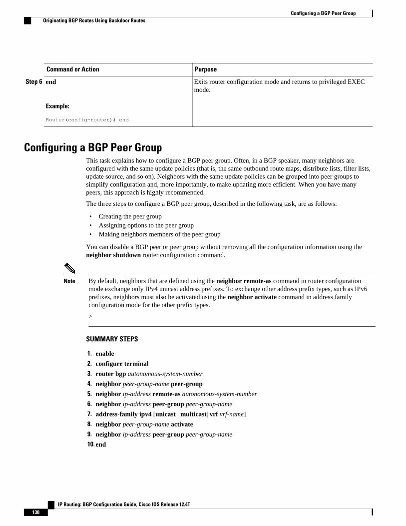
Command or Action Purpose
Step 6 end
Example:
Router(config-router)# end
Exits router configuration mode and returns to privileged EXECmode.
Configuring a BGP Peer GroupThis task explains how to configure a BGP peer group. Often, in a BGP speaker, many neighbors areconfigured with the same update policies (that is, the same outbound route maps, distribute lists, filter lists,update source, and so on). Neighbors with the same update policies can be grouped into peer groups tosimplify configuration and, more importantly, to make updating more efficient. When you have manypeers, this approach is highly recommended.
The three steps to configure a BGP peer group, described in the following task, are as follows:
• Creating the peer group• Assigning options to the peer group• Making neighbors members of the peer group
You can disable a BGP peer or peer group without removing all the configuration information using theneighbor shutdown router configuration command.
Note By default, neighbors that are defined using the neighbor remote-as command in router configurationmode exchange only IPv4 unicast address prefixes. To exchange other address prefix types, such as IPv6prefixes, neighbors must also be activated using the neighbor activate command in address familyconfiguration mode for the other prefix types.
>
SUMMARY STEPS
1. enable
2. configure terminal
3. router bgp autonomous-system-number
4. neighbor peer-group-name peer-group
5. neighbor ip-address remote-as autonomous-system-number
6. neighbor ip-address peer-group peer-group-name
7. address-family ipv4 [unicast | multicast| vrf vrf-name]
8. neighbor peer-group-name activate
9. neighbor ip-address peer-group peer-group-name
10. end
Configuring a BGP Peer Group Originating BGP Routes Using Backdoor Routes
IP Routing: BGP Configuration Guide, Cisco IOS Release 12.4T130
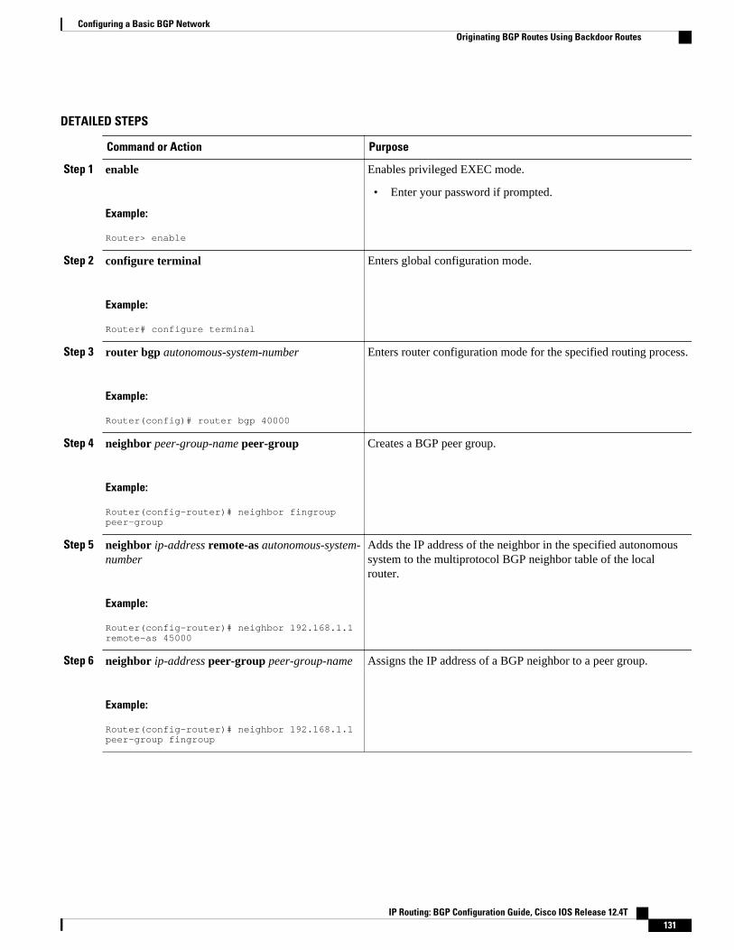
DETAILED STEPS
Command or Action Purpose
Step 1 enable
Example:
Router> enable
Enables privileged EXEC mode.
• Enter your password if prompted.
Step 2 configure terminal
Example:
Router# configure terminal
Enters global configuration mode.
Step 3 router bgp autonomous-system-number
Example:
Router(config)# router bgp 40000
Enters router configuration mode for the specified routing process.
Step 4 neighbor peer-group-name peer-group
Example:
Router(config-router)# neighbor fingroup peer-group
Creates a BGP peer group.
Step 5 neighbor ip-address remote-as autonomous-system-number
Example:
Router(config-router)# neighbor 192.168.1.1 remote-as 45000
Adds the IP address of the neighbor in the specified autonomoussystem to the multiprotocol BGP neighbor table of the localrouter.
Step 6 neighbor ip-address peer-group peer-group-name
Example:
Router(config-router)# neighbor 192.168.1.1 peer-group fingroup
Assigns the IP address of a BGP neighbor to a peer group.
Configuring a Basic BGP NetworkOriginating BGP Routes Using Backdoor Routes
IP Routing: BGP Configuration Guide, Cisco IOS Release 12.4T 131

Command or Action Purpose
Step 7 address-family ipv4 [unicast | multicast| vrf vrf-name]
Example:
Router(config-router)# address-family ipv4 multicast
Specifies the IPv4 address family and enters address familyconfiguration mode.
• The unicast keyword specifies the IPv4 unicast addressfamily. This is the default.
• The multicast keyword specifies that IPv4 multicast addressprefixes will be exchanged.
• The vrfkeyword and vrf-name argument specify that IPv4VRF instance information will be exchanged.
Step 8 neighbor peer-group-name activate
Example:
Router(config-router-af)# neighbor fingroup activate
Enables the neighbor to exchange prefixes for the IPv4 addressfamily with the local router.
Note By default, neighbors that are defined using the neighborremote-as command in router configuration modeexchange only unicast address prefixes. To allow BGP toexchange other address prefix types, such as multicast thatis configured in this example, neighbors must also beactivated using the neighbor activate command.
Step 9 neighbor ip-address peer-group peer-group-name
Example:
Router(config-router-af)# neighbor 192.168.1.1 peer-group fingroup
Assigns the IP address of a BGP neighbor to a peer group.
Step 10 end
Example:
Router(config-router-af)# end
Exits address family configuration mode and returns to privilegedEXEC mode.
Configuring Peer Session TemplatesThe following tasks create and configure a peer session template:
• Configuring a Basic Peer Session Template, page 132
• Configuring Peer Session Template Inheritance with the inherit peer-session Command, page 135
• Configuring Peer Session Template Inheritance with the neighbor inherit peer-session Command, page 137
Configuring a Basic Peer Session TemplatePerform this task to create a basic peer session template with general BGP routing session commands thatcan be applied to many neighbors using one of the next two tasks.
Configuring Peer Session Templates Configuring a Basic Peer Session Template
IP Routing: BGP Configuration Guide, Cisco IOS Release 12.4T132

Note The commands in Step 5 and 6 are optional and could be replaced with any supported general sessioncommands.
Note The following restrictions apply to the peer session templates:
• A peer session template can directly inherit only one session template, and each inherited sessiontemplate can also contain one indirectly inherited session template. So, a neighbor or neighbor groupcan be configured with only one directly applied peer session template and seven additional indirectlyinherited peer session templates.
• A BGP neighbor cannot be configured to work with both peer groups and peer templates. A BGPneighbor can be configured to belong only to a peer group or to inherit policies only from peertemplates.
>
SUMMARY STEPS
1. enable
2. configure terminal
3. router bgp autonomous-system-number
4. template peer-session session-template-name
5. remote-as autonomous-system-number
6. timers keepalive-interval hold-time
7. end
8. show ip bgp template peer-session [session-template-name]
DETAILED STEPS
Command or Action Purpose
Step 1 enable
Example:
Router> enable
Enables privileged EXEC mode.
• Enter your password if prompted.
Step 2 configure terminal
Example:
Router# configure terminal
Enters global configuration mode.
Configuring a Basic BGP NetworkConfiguring a Basic Peer Session Template
IP Routing: BGP Configuration Guide, Cisco IOS Release 12.4T 133

Command or Action Purpose
Step 3 router bgp autonomous-system-number
Example:
Router(config)# router bgp 101
Enters router configuration mode and creates a BGP routingprocess.
Step 4 template peer-session session-template-name
Example:
Router(config-router)# template peer-session INTERNAL-BGP
Enters session-template configuration mode and creates a peersession template.
Step 5 remote-as autonomous-system-number
Example:
Router(config-router-stmp)# remote-as 202
(Optional) Configures peering with a remote neighbor in thespecified autonomous system.
Note Any supported general session command can be used here.For a list of the supported commands, see the "Restrictions"section.
Step 6 timers keepalive-interval hold-time
Example:
Router(config-router-stmp)# timers 30 300
(Optional) Configures BGP keepalive and hold timers.
• The hold time must be at least twice the keepalive time.
Note Any supported general session command can be used here.For a list of the supported commands, see the "Restrictions"section.
Step 7 end
Example:
Router(config-router)# end
Exits session-template configuration mode and returns to privilegedEXEC mode.
Step 8 show ip bgp template peer-session [session-template-name]
Example:
Router# show ip bgp template peer-session
Displays locally configured peer session templates.
• The output can be filtered to display a single peer policytemplate with the session-template-name argument. Thiscommand also supports all standard output modifiers.
• What to Do Next, page 134
What to Do Next
After the peer session template is created, the configuration of the peer session template can be inherited orapplied by another peer session template with the inherit peer-session or neighbor inherit peer-sessioncommand.
Configuring a Basic BGP Network What to Do Next
IP Routing: BGP Configuration Guide, Cisco IOS Release 12.4T134

Configuring Peer Session Template Inheritance with the inherit peer-session CommandThis task configures peer session template inheritance with the inherit peer-session command. It createsand configures a peer session template and allows it to inherit a configuration from another peer sessiontemplate.
Note The commands in Steps 5 and 6 are optional and could be replaced with any supported general sessioncommands.
SUMMARY STEPS
1. enable
2. configure terminal
3. router bgp autonomous-system-number
4. template peer-session session-template-name
5. description text-string
6. update-source interface-type interface-number
7. inherit peer-session session-template-name
8. end
9. show ip bgp template peer-session [session-template-name]
DETAILED STEPS
Command or Action Purpose
Step 1 enable
Example:
Router> enable
Enables privileged EXEC mode.
• Enter your password if prompted.
Step 2 configure terminal
Example:
Router# configure terminal
Enters global configuration mode.
Step 3 router bgp autonomous-system-number
Example:
Router(config)# router bgp 101
Enters router configuration mode and creates a BGP routing process.
Configuring a Basic BGP NetworkConfiguring Peer Session Template Inheritance with the inherit peer-session Command
IP Routing: BGP Configuration Guide, Cisco IOS Release 12.4T 135

Command or Action Purpose
Step 4 template peer-session session-template-name
Example:
Router(config-router)# template peer-session CORE1
Enter session-template configuration mode and creates a peer sessiontemplate.
Step 5 description text-string
Example:
Router(config-router-stmp)# description CORE-123
(Optional) Configures a description.
• The text string can be up to 80 characters.
Note Any supported general session command can be used here. For a listof the supported commands, see the "Restrictions" section.
Step 6 update-source interface-type interface-number
Example:
Router(config-router-stmp)# update-source loopback 1
(Optional) Configures a router to select a specific source or interface toreceive routing table updates.
• The example uses a loopback interface. The advantage to thisconfiguration is that the loopback interface is not as susceptible to theeffects of a flapping interface.
Note Any supported general session command can be used here. For a listof the supported commands, see the "Restrictions" section.
Step 7 inherit peer-session session-template-name
Example:
Router(config-router-stmp)# inherit peer-session INTERNAL-BGP
Configures this peer session template to inherit the configuration ofanother peer session template.
• The example configures this peer session template to inherit theconfiguration from INTERNAL-BGP. This template can be applied toa neighbor, and the configuration INTERNAL-BGP will be appliedindirectly. No additional peer session templates can be directlyapplied. However, the directly inherited template can contain up toseven indirectly inherited peer session templates.
Step 8 end
Example:
Router(config-router)# end
Exits session-template configuration mode and enters privileged EXECmode.
Step 9 show ip bgp template peer-session [session-template-name]
Example:
Router# show ip bgp template peer-session
Displays locally configured peer session templates.
• The output can be filtered to display a single peer policy templatewith the optional session-template-name argument. This commandalso supports all standard output modifiers.
• What to Do Next, page 137
Configuring a Basic BGP Network Configuring Peer Session Template Inheritance with the inherit peer-session Command
IP Routing: BGP Configuration Guide, Cisco IOS Release 12.4T136

What to Do Next
After the peer session template is created, the configuration of the peer session template can be inherited orapplied by another peer session template with the inherit peer-session or neighbor inherit peer-sessioncommand.
Configuring Peer Session Template Inheritance with the neighbor inherit peer-sessionCommand
This task configures a router to send a peer session template to a neighbor to inherit the configuration fromthe specified peer session template with the neighbor inherit peer-session command. Use the followingsteps to send a peer session template configuration to a neighbor to inherit:
SUMMARY STEPS
1. enable
2. configure terminal
3. router bgp autonomous-system-number
4. neighbor ip-address remote-as autonomous-system-number
5. neighbor ip-address inherit peer-session session-template-name
6. end
7. show ip bgp template peer-session [session-template-name]
DETAILED STEPS
Command or Action Purpose
Step 1 enable
Example:
Router> enable
Enables privileged EXEC mode.
• Enter your password if prompted.
Step 2 configure terminal
Example:
Router# configure terminal
Enters global configuration mode.
Step 3 router bgp autonomous-system-number
Example:
Router(config)# router bgp 101
Enters router configuration mode and creates a BGP routing process.
Configuring a Basic BGP NetworkWhat to Do Next
IP Routing: BGP Configuration Guide, Cisco IOS Release 12.4T 137
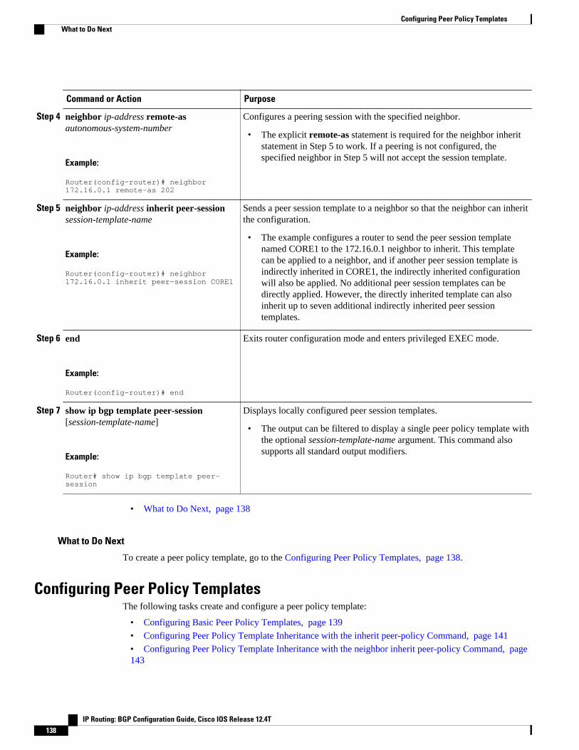
Command or Action Purpose
Step 4 neighbor ip-address remote-asautonomous-system-number
Example:
Router(config-router)# neighbor 172.16.0.1 remote-as 202
Configures a peering session with the specified neighbor.
• The explicit remote-as statement is required for the neighbor inheritstatement in Step 5 to work. If a peering is not configured, thespecified neighbor in Step 5 will not accept the session template.
Step 5 neighbor ip-address inherit peer-sessionsession-template-name
Example:
Router(config-router)# neighbor 172.16.0.1 inherit peer-session CORE1
Sends a peer session template to a neighbor so that the neighbor can inheritthe configuration.
• The example configures a router to send the peer session templatenamed CORE1 to the 172.16.0.1 neighbor to inherit. This templatecan be applied to a neighbor, and if another peer session template isindirectly inherited in CORE1, the indirectly inherited configurationwill also be applied. No additional peer session templates can bedirectly applied. However, the directly inherited template can alsoinherit up to seven additional indirectly inherited peer sessiontemplates.
Step 6 end
Example:
Router(config-router)# end
Exits router configuration mode and enters privileged EXEC mode.
Step 7 show ip bgp template peer-session[session-template-name]
Example:
Router# show ip bgp template peer-session
Displays locally configured peer session templates.
• The output can be filtered to display a single peer policy template withthe optional session-template-name argument. This command alsosupports all standard output modifiers.
• What to Do Next, page 138
What to Do Next
To create a peer policy template, go to the Configuring Peer Policy Templates, page 138.
Configuring Peer Policy TemplatesThe following tasks create and configure a peer policy template:
• Configuring Basic Peer Policy Templates, page 139
• Configuring Peer Policy Template Inheritance with the inherit peer-policy Command, page 141
• Configuring Peer Policy Template Inheritance with the neighbor inherit peer-policy Command, page143
Configuring Peer Policy Templates What to Do Next
IP Routing: BGP Configuration Guide, Cisco IOS Release 12.4T138
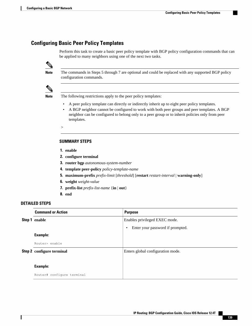
Configuring Basic Peer Policy TemplatesPerform this task to create a basic peer policy template with BGP policy configuration commands that canbe applied to many neighbors using one of the next two tasks.
Note The commands in Steps 5 through 7 are optional and could be replaced with any supported BGP policyconfiguration commands.
Note The following restrictions apply to the peer policy templates:
• A peer policy template can directly or indirectly inherit up to eight peer policy templates.• A BGP neighbor cannot be configured to work with both peer groups and peer templates. A BGP
neighbor can be configured to belong only to a peer group or to inherit policies only from peertemplates.
>
SUMMARY STEPS
1. enable
2. configure terminal
3. router bgp autonomous-system-number
4. template peer-policy policy-template-name
5. maximum-prefix prefix-limit [threshold] [restart restart-interval | warning-only]
6. weight weight-value
7. prefix-list prefix-list-name {in | out}
8. end
DETAILED STEPS
Command or Action Purpose
Step 1 enable
Example:
Router> enable
Enables privileged EXEC mode.
• Enter your password if prompted.
Step 2 configure terminal
Example:
Router# configure terminal
Enters global configuration mode.
Configuring a Basic BGP NetworkConfiguring Basic Peer Policy Templates
IP Routing: BGP Configuration Guide, Cisco IOS Release 12.4T 139

Command or Action Purpose
Step 3 router bgp autonomous-system-number
Example:
Router(config)# router bgp 45000
Enters router configuration mode and creates a BGP routingprocess.
Step 4 template peer-policy policy-template-name
Example:
Router(config-router)# template peer-policy GLOBAL
Enters policy-template configuration mode and creates a peerpolicy template.
Step 5 maximum-prefix prefix-limit [threshold] [restartrestart-interval | warning-only]
Example:
Router(config-router-ptmp)# maximum-prefix 10000
(Optional) Configures the maximum number of prefixes that aneighbor will accept from this peer.
Note Any supported BGP policy configuration command can beused here. For a list of the supported commands, see the PeerPolicy Templates, page 80.
Step 6 weight weight-value
Example:
Router(config-router-ptmp)# weight 300
(Optional) Sets the default weight for routes that are sent from thisneighbor.
Note Any supported BGP policy configuration command can beused here. For a list of the supported commands, see the PeerPolicy Templates, page 80.
Step 7 prefix-list prefix-list-name {in | out}
Example:
Router(config-router-ptmp)# prefix-list NO-MARKETING in
(Optional) Filters prefixes that are received by the router or sentfrom the router.
• The prefix list in the example filters inbound internaladdresses.
Note Any supported BGP policy configuration command can beused here. For a list of the supported commands, see the PeerPolicy Templates, page 80.
Step 8 end
Example:
Router(config-router-ptmp)# end
Exits policy-template configuration mode and returns to privilegedEXEC mode.
• What to Do Next, page 140
What to Do NextAfter the peer policy template is created, the configuration of the peer policy template can be inherited orapplied by another peer policy template. For more details about peer policy inheritance see the
Configuring a Basic BGP Network What to Do Next
IP Routing: BGP Configuration Guide, Cisco IOS Release 12.4T140

"Configuring Peer Policy Template Inheritance with the inherit peer-policy Command" section or the"Configuring Peer Policy Template Inheritance with the neighbor inherit peer-policy Command" section.
Configuring Peer Policy Template Inheritance with the inherit peer-policy CommandThis task configures peer policy template inheritance using the inherit peer-policycommand. It creates andconfigure a peer policy template and allows it to inherit a configuration from another peer policy template.
When BGP neighbors use inherited peer templates, it can be difficult to determine which policies areassociated with a specific template. In Cisco IOS Release 12.0(25)S, 12.4(11)T, 12.2(33)SRB, 12.2(33)SB,and later releases, the detail keyword was added to the show ip bgp template peer-policy command todisplay the detailed configuration of local and inherited policies associated with a specific template.
Note The commands in Steps 5 and 6 are optional and could be replaced with any supported BGP policyconfiguration commands.
SUMMARY STEPS
1. enable
2. configure terminal
3. router bgp autonomous-system-number
4. template peer-policy policy-template-name
5. route-map map-name {in| out}
6. inherit peer-policy policy-template-name sequence-number
7. end
8. show ip bgp template peer-policy [policy-template-name[detail]]
DETAILED STEPS
Command or Action Purpose
Step 1 enable
Example:
Router> enable
Enables privileged EXEC mode.
• Enter your password if prompted.
Step 2 configure terminal
Example:
Router# configure terminal
Enters global configuration mode.
Configuring a Basic BGP NetworkConfiguring Peer Policy Template Inheritance with the inherit peer-policy Command
IP Routing: BGP Configuration Guide, Cisco IOS Release 12.4T 141

Command or Action Purpose
Step 3 router bgp autonomous-system-number
Example:
Router(config)# router bgp 45000
Enters router configuration mode and creates a BGP routing process.
Step 4 template peer-policy policy-template-name
Example:
Router(config-router)# template peer-policy NETWORK1
Enter policy-template configuration mode and creates a peer policytemplate.
Step 5 route-map map-name {in| out}
Example:
Router(config-router-ptmp)# route-map ROUTE in
(Optional) Applies the specified route map to inbound or outbound routes.
Note Any supported BGP policy configuration command can be used here.For a list of the supported commands, see the Peer PolicyTemplates, page 80.
Step 6 inherit peer-policy policy-template-namesequence-number
Example:
Router(config-router-ptmp)# inherit peer-policy GLOBAL 10
Configures the peer policy template to inherit the configuration of anotherpeer policy template.
• The sequence-number argument sets the order in which the peer policytemplate is evaluated. Like a route map sequence number, the lowestsequence number is evaluated first.
• The example configures this peer policy template to inherit theconfiguration from GLOBAL. If the template created in these steps isapplied to a neighbor, the configuration GLOBAL will also beinherited and applied indirectly. Up to six additional peer policytemplates can be indirectly inherited from GLOBAL for a total of eightdirectly applied and indirectly inherited peer policy templates.
• This template in the example will be evaluated first if no othertemplates are configured with a lower sequence number.
Step 7 end
Example:
Router(config-router-ptmp)# end
Exits policy-template configuration mode and returns to privileged EXECmode.
Configuring a Basic BGP Network Configuring Peer Policy Template Inheritance with the inherit peer-policy Command
IP Routing: BGP Configuration Guide, Cisco IOS Release 12.4T142
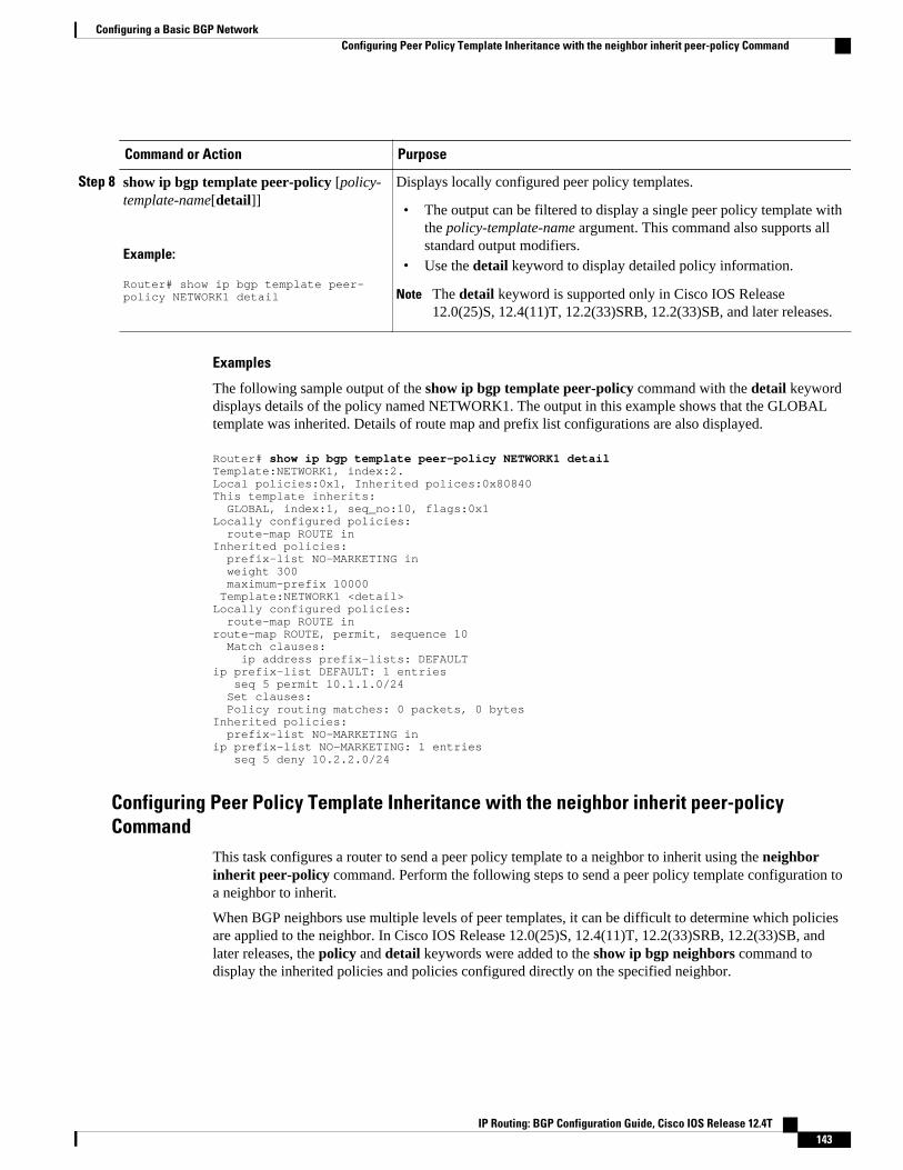
Command or Action Purpose
Step 8 show ip bgp template peer-policy [policy-template-name[detail]]
Example:
Router# show ip bgp template peer-policy NETWORK1 detail
Displays locally configured peer policy templates.
• The output can be filtered to display a single peer policy template withthe policy-template-name argument. This command also supports allstandard output modifiers.
• Use the detail keyword to display detailed policy information.
Note The detail keyword is supported only in Cisco IOS Release12.0(25)S, 12.4(11)T, 12.2(33)SRB, 12.2(33)SB, and later releases.
Examples
The following sample output of the show ip bgp template peer-policy command with the detail keyworddisplays details of the policy named NETWORK1. The output in this example shows that the GLOBALtemplate was inherited. Details of route map and prefix list configurations are also displayed.
Router# show ip bgp template peer-policy NETWORK1 detailTemplate:NETWORK1, index:2.Local policies:0x1, Inherited polices:0x80840This template inherits: GLOBAL, index:1, seq_no:10, flags:0x1Locally configured policies: route-map ROUTE inInherited policies: prefix-list NO-MARKETING in weight 300 maximum-prefix 10000 Template:NETWORK1 <detail>Locally configured policies: route-map ROUTE inroute-map ROUTE, permit, sequence 10 Match clauses: ip address prefix-lists: DEFAULT ip prefix-list DEFAULT: 1 entries seq 5 permit 10.1.1.0/24 Set clauses: Policy routing matches: 0 packets, 0 bytesInherited policies: prefix-list NO-MARKETING inip prefix-list NO-MARKETING: 1 entries seq 5 deny 10.2.2.0/24
Configuring Peer Policy Template Inheritance with the neighbor inherit peer-policyCommand
This task configures a router to send a peer policy template to a neighbor to inherit using the neighborinherit peer-policy command. Perform the following steps to send a peer policy template configuration toa neighbor to inherit.
When BGP neighbors use multiple levels of peer templates, it can be difficult to determine which policiesare applied to the neighbor. In Cisco IOS Release 12.0(25)S, 12.4(11)T, 12.2(33)SRB, 12.2(33)SB, andlater releases, the policy and detail keywords were added to the show ip bgp neighbors command todisplay the inherited policies and policies configured directly on the specified neighbor.
Configuring a Basic BGP NetworkConfiguring Peer Policy Template Inheritance with the neighbor inherit peer-policy Command
IP Routing: BGP Configuration Guide, Cisco IOS Release 12.4T 143

SUMMARY STEPS
1. enable
2. configure terminal
3. router bgp autonomous-system-number
4. neighbor ip-address remote-as autonomous-system-number
5. address-family ipv4 [multicast | unicast | vrf vrf-name]
6. neighbor ip-address inherit peer-policy policy-template-name
7. end
8. show ip bgp neighbors [ip-address[policy [detail]]]
DETAILED STEPS
Command or Action Purpose
Step 1 enable
Example:
Router> enable
Enables privileged EXEC mode.
• Enter your password if prompted.
Step 2 configure terminal
Example:
Router# configure terminal
Enters global configuration mode.
Step 3 router bgp autonomous-system-number
Example:
Router(config)# router bgp 45000
Enters router configuration mode and creates a BGP routing process.
Step 4 neighbor ip-address remote-asautonomous-system-number
Example:
Router(config-router)# neighbor 192.168.1.2 remote-as 40000
Configures a peering session with the specified neighbor.
• The explicit remote-as statement is required for the neighbor inheritstatement in Step 6 to work. If a peering is not configured, the specifiedneighbor in Step 6 will not accept the session template.
Step 5 address-family ipv4 [multicast | unicast |vrf vrf-name]
Example:
Router(config-router)# address-family ipv4 unicast
Enters address family configuration mode to configure a neighbor to acceptaddress family-specific command configurations.
Configuring a Basic BGP Network Configuring Peer Policy Template Inheritance with the neighbor inherit peer-policy Command
IP Routing: BGP Configuration Guide, Cisco IOS Release 12.4T144

Command or Action Purpose
Step 6 neighbor ip-address inherit peer-policypolicy-template-name
Example:
Router(config-router-af)# neighbor 192.168.1.2 inherit peer-policy GLOBAL
Sends a peer policy template to a neighbor so that the neighbor can inheritthe configuration.
• The example configures a router to send the peer policy template namedGLOBAL to the 192.168.1.2 neighbor to inherit. This template can beapplied to a neighbor, and if another peer policy template is indirectlyinherited from GLOBAL, the indirectly inherited configuration will alsobe applied. Up to seven additional peer policy templates can beindirectly inherited from GLOBAL.
Step 7 end
Example:
Router(config-router-af)# end
Exits address family configuration mode and returns to privileged EXECmode.
Step 8 show ip bgp neighbors [ip-address[policy[detail]]]
Example:
Router# show ip bgp neighbors 192.168.1.2 policy
Displays locally configured peer policy templates.
• The output can be filtered to display a single peer policy template withthe policy-template-name argument. This command also supports allstandard output modifiers.
• Use the policy keyword to display the policies applied to this neighborper address family.
• Use the detail keyword to display detailed policy information.• The policy and detail keywords are supported only in Cisco IOS
Release 12.0(25)S, 12.4(11)T, 12.2(33)SRB, 12.2(33)SB, and laterreleases.
Note Only the syntax required for this task is shown. For more details, seethe Cisco IOS IP Routing: BGP Command Reference.
Examples
The following sample output shows the policies applied to the neighbor at 192.168.1.2. The output displaysboth inherited policies and policies configured on the neighbor device. Inherited polices are policies thatthe neighbor inherits from a peer-group or a peer-policy template.
Router# show ip bgp neighbors 192.168.1.2 policyNeighbor: 192.168.1.2, Address-Family: IPv4 UnicastLocally configured policies: route-map ROUTE inInherited polices: prefix-list NO-MARKETING in route-map ROUTE in weight 300 maximum-prefix 10000
Monitoring and Maintaining BGP Dynamic Update GroupsUse this task to clear and display information about the processing of dynamic BGP update groups. Theperformance of BGP update message generation is improved with the use of BGP update groups. With theconfiguration of the BGP peer templates and the support of the dynamic BGP update groups, the network
Monitoring and Maintaining BGP Dynamic Update GroupsConfiguring Peer Policy Template Inheritance with the neighbor inherit peer-policy Command
IP Routing: BGP Configuration Guide, Cisco IOS Release 12.4T 145
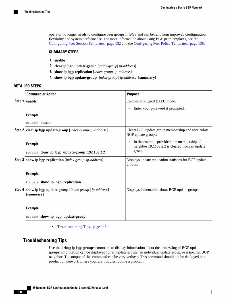
operator no longer needs to configure peer groups in BGP and can benefit from improved configurationflexibility and system performance. For more information about using BGP peer templates, see the Configuring Peer Session Templates, page 132 and the Configuring Peer Policy Templates, page 138.
SUMMARY STEPS
1. enable
2. clear ip bgp update-group [index-group| ip-address]
3. show ip bgp replication [index-group| ip-address]
4. show ip bgp update-group [index-group | ip-address] [summary]
DETAILED STEPS
Command or Action Purpose
Step 1 enable
Example:
Router> enable
Enables privileged EXEC mode.
• Enter your password if prompted.
Step 2 clear ip bgp update-group [index-group| ip-address]
Example:
Router# clear ip bgp update-group 192.168.2.2
Clears BGP update group membership and recalculateBGP update groups:
• In the example provided, the membership ofneighbor 192.168.2.2 is cleared from an updategroup.
Step 3 show ip bgp replication [index-group| ip-address]
Example:
Router# show ip bgp replication
Displays update replication statistics for BGP updategroups.
Step 4 show ip bgp update-group [index-group | ip-address][summary]
Example:
Router# show ip bgp update-group
Displays information about BGP update groups.
• Troubleshooting Tips, page 146
Troubleshooting TipsUse the debug ip bgp groups command to display information about the processing of BGP updategroups. Information can be displayed for all update groups, an individual update group, or a specific BGPneighbor. The output of this command can be very verbose. This command should not be deployed in aproduction network unless your are troubleshooting a problem.
Configuring a Basic BGP Network Troubleshooting Tips
IP Routing: BGP Configuration Guide, Cisco IOS Release 12.4T146

Configuration Examples for a Basic BGP Network• Example Configuring a BGP Process and Customizing Peers, page 147
• Examples Configuring a BGP Routing Process and Peers Using 4-Byte Autonomous SystemNumbers, page 148
• Examples Configuring a VRF and Setting an Extended Community Using a BGP 4-Byte AutonomousSystem Number, page 150
• Example NLRI to AFI Configuration, page 151
• Examples Removing BGP Configuration Commands Using a Redistribution Example, page 153
• Examples BGP Soft Reset, page 154
• Example Resetting BGP Peers Using 4-Byte Autonomous System Numbers, page 154
• Example Resetting and Displaying Basic BGP Information, page 155
• Examples Aggregating Prefixes Using BGP, page 156
• Example Configuring a BGP Peer Group, page 157
• Example Configuring Peer Session Templates, page 158
• Example Configuring Peer Policy Templates, page 158
• Examples Monitoring and Maintaining BGP Dynamic Update Peer-Groups, page 159
Example Configuring a BGP Process and Customizing PeersThe following example shows the configuration for Router B in the figure above (in the "Customizing aBGP Peer" section) with a BGP process configured with two neighbor peers (at Router A and at Router E)in separate autonomous systems. IPv4 unicast routes are exchanged with both peers and IPv4 multicastroutes are exchanged with the BGP peer at Router E.
Router B
router bgp 45000 bgp router-id 172.17.1.99 no bgp default ipv4-unicast bgp log-neighbor-changes timers bgp 70 120 neighbor 192.168.1.2 remote-as 40000 neighbor 192.168.3.2 remote-as 50000 neighbor 192.168.3.2 description finance ! address-family ipv4 neighbor 192.168.1.2 activate neighbor 192.168.3.2 activate no auto-summary no synchronization network 172.17.1.0 mask 255.255.255.0 exit-address-family ! address-family ipv4 multicast neighbor 192.168.3.2 activate neighbor 192.168.3.2 advertisement-interval 25 no auto-summary no synchronization network 172.17.1.0 mask 255.255.255.0 exit-address-family
Example Configuring a BGP Process and Customizing PeersConfiguration Examples for a Basic BGP Network
IP Routing: BGP Configuration Guide, Cisco IOS Release 12.4T 147

Examples Configuring a BGP Routing Process and Peers Using 4-ByteAutonomous System Numbers
Asplain Default Format in Cisco IOS Release 12.0(32)SY8, 12.0(33)S3, 12.2(33)SRE, 12.2(33)SXI1, and LaterReleases
The following example is available in Cisco IOS Release 12.0(32)SY8, 12.0(33)S3, 12.2(33)SRE,12.2(33)XNE, 12.2(33)SXI1, and later releases and shows the configuration for Router A, Router B, andRouter E in the figure below with a BGP process configured between three neighbor peers (at Router A, atRouter B, and at Router E) in separate 4-byte autonomous systems configured using asplain notation. IPv4unicast routes are exchanged with all peers.
Figure 13 BGP Peers Using 4-Byte Autonomous System Numbers in Asplain Format
Router A
router bgp 65536 bgp router-id 10.1.1.99 no bgp default ipv4-unicast bgp fast-external-fallover bgp log-neighbor-changes timers bgp 70 120 neighbor 192.168.1.1 remote-as 65538 ! address-family ipv4 neighbor 192.168.1.1 activate no auto-summary no synchronization network 10.1.1.0 mask 255.255.255.0 exit-address-family
Router B
router bgp 65538 bgp router-id 172.17.1.99 no bgp default ipv4-unicast
Examples Configuring a BGP Routing Process and Peers Using 4-Byte Autonomous System Numbers Configuration Examples for a Basic BGP Network
IP Routing: BGP Configuration Guide, Cisco IOS Release 12.4T148

bgp fast-external-fallover bgp log-neighbor-changes timers bgp 70 120 neighbor 192.168.1.2 remote-as 65536 neighbor 192.168.3.2 remote-as 65550 neighbor 192.168.3.2 description finance ! address-family ipv4 neighbor 192.168.1.2 activate neighbor 192.168.3.2 activate no auto-summary no synchronization network 172.17.1.0 mask 255.255.255.0 exit-address-family
Router E
router bgp 65550 bgp router-id 10.2.2.99 no bgp default ipv4-unicast bgp fast-external-fallover bgp log-neighbor-changes timers bgp 70 120 neighbor 192.168.3.1 remote-as 65538 ! address-family ipv4 neighbor 192.168.3.1 activate no auto-summary no synchronization network 10.2.2.0 mask 255.255.255.0 exit-address-family
Asdot Default Format in Cisco IOS Release 12.0(32)S12, and 12.4(24)T
The following example is available in Cisco IOS Release 12.0(32)S12, and 12.4(24)T and shows how tocreate the configuration for Router A, Router B, and Router E in the figure below with a BGP processconfigured between three neighbor peers (at Router A, at Router B, and at Router E) in separate 4-byteautonomous systems configured using the default asdot format. IPv4 unicast routes are exchanged with allpeers.
Figure 14 BGP Peers Using 4-Byte Autonomous System Numbers in Asdot Format
Configuring a Basic BGP NetworkConfiguration Examples for a Basic BGP Network
IP Routing: BGP Configuration Guide, Cisco IOS Release 12.4T 149

Router A
router bgp 1.0 bgp router-id 10.1.1.99 no bgp default ipv4-unicast bgp fast-external-fallover bgp log-neighbor-changes timers bgp 70 120 neighbor 192.168.1.1 remote-as 1.2 ! address-family ipv4 neighbor 192.168.1.1 activate no auto-summary no synchronization network 10.1.1.0 mask 255.255.255.0 exit-address-family
Router B
router bgp 1.2 bgp router-id 172.17.1.99 no bgp default ipv4-unicast bgp fast-external-fallover bgp log-neighbor-changes timers bgp 70 120 neighbor 192.168.1.2 remote-as 1.0 neighbor 192.168.3.2 remote-as 1.14 neighbor 192.168.3.2 description finance ! address-family ipv4 neighbor 192.168.1.2 activate neighbor 192.168.3.2 activate no auto-summary no synchronization network 172.17.1.0 mask 255.255.255.0 exit-address-family
Router E
router bgp 1.14 bgp router-id 10.2.2.99 no bgp default ipv4-unicast bgp fast-external-fallover bgp log-neighbor-changes timers bgp 70 120 neighbor 192.168.3.1 remote-as 1.2 ! address-family ipv4 neighbor 192.168.3.1 activate no auto-summary no synchronization network 10.2.2.0 mask 255.255.255.0 exit-address-family
Examples Configuring a VRF and Setting an Extended Community Using aBGP 4-Byte Autonomous System Number
Asplain Default Format in Cisco IOS Release 12.0(32)SY8, 12.0(33)S3, 12.2(33)SRE, 12.2(33)SXI1, and LaterReleases
The following example is available in Cisco IOS Release 12.0(32)SY8, 12.0(33)S3, 12.2(33)SRE,12.2(33)XNE, 12.2(33)SXI1, and later releases and shows how to create a VRF with a route-target that
Examples Configuring a VRF and Setting an Extended Community Using a BGP 4-Byte Autonomous System Number Configuration Examples for a Basic BGP Network
IP Routing: BGP Configuration Guide, Cisco IOS Release 12.4T150

uses a 4-byte autonomous system number, 65537, and how to set the route target to extended communityvalue 65537:100 for routes that are permitted by the route map.
ip vrf vpn_red rd 64500:100 route-target both 65537:100 exitroute-map red_map permit 10 set extcommunity rt 65537:100 end
After the configuration is completed, use the show route-map command to verify that the extendedcommunity is set to the route target that contains the 4-byte autonomous system number of 65537.
RouterB# show route-map red_maproute-map red_map, permit, sequence 10 Match clauses: Set clauses: extended community RT:65537:100 Policy routing matches: 0 packets, 0 bytes
Asdot Default Format in Cisco IOS Release 12.0(32)S12, and 12.4(24)T
The following example is available in Cisco IOS Release 12.0(32)S12, and 12.4(24)T and shows how tocreate a VRF with a route-target that uses a 4-byte autonomous system number, 1.1, and how to set theroute target to extended community value 1.1:100 for routes that are permitted by the route map.
Note In Cisco IOS Release 12.0(32)SY8, 12.0(33)S3, 12.2(33)SXI1, and later releases, this example works ifyou have configured asdot as the default display format using the bgp asnotation dot command.
ip vrf vpn_red rd 64500:100 route-target both 1.1:100 exitroute-map red_map permit 10 set extcommunity rt 1.1:100 end
After the configuration is completed, use the show route-map command to verify that the extendedcommunity is set to the route target that contains the 4-byte autonomous system number of 1.1.
RouterB# show route-map red_maproute-map red_map, permit, sequence 10 Match clauses: Set clauses: extended community RT:1.1:100 Policy routing matches: 0 packets, 0 bytes
Example NLRI to AFI ConfigurationThe following example upgrades an existing router configuration file in the NLRI format to the AFI formatand set the router CLI to use only commands in the AFI format:
router bgp 60000 bgp upgrade-cli
The show running-config command can be used in privileged EXEC mode to verify that an existing routerconfiguration file has been upgraded from the NLRI format to the AFI format. The following sectionsprovide sample output from a router configuration file in the NLRI format, and the same router
Example NLRI to AFI ConfigurationConfiguration Examples for a Basic BGP Network
IP Routing: BGP Configuration Guide, Cisco IOS Release 12.4T 151
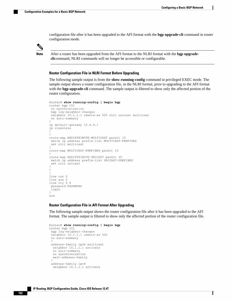
configuration file after it has been upgraded to the AFI format with the bgp upgrade-cli command in routerconfiguration mode.
Note After a router has been upgraded from the AFI format to the NLRI format with the bgp upgrade-clicommand, NLRI commands will no longer be accessible or configurable.
Router Configuration File in NLRI Format Before Upgrading
The following sample output is from the show running-config command in privileged EXEC mode. Thesample output shows a router configuration file, in the NLRI format, prior to upgrading to the AFI formatwith the bgp upgrade-cli command. The sample output is filtered to show only the affected portion of therouter configuration.
Router# show running-config | begin bgprouter bgp 101 no synchronization bgp log-neighbor-changes neighbor 10.1.1.1 remote-as 505 nlri unicast multicast no auto-summary!ip default-gateway 10.4.9.1ip classless!!route-map REDISTRIBUTE-MULTICAST permit 10 match ip address prefix-list MULTICAST-PREFIXES set nlri multicast!route-map MULTICAST-PREFIXES permit 10!route-map REDISTRIBUTE-UNICAST permit 20 match ip address prefix-list UNICAST-PREFIXES set nlri unicast !!!line con 0line aux 0line vty 0 4 password PASSWORD login!end
Router Configuration File in AFI Format After Upgrading
The following sample output shows the router configuration file after it has been upgraded to the AFIformat. The sample output is filtered to show only the affected portion of the router configuration file.
Router# show running-config | begin bgprouter bgp 101 bgp log-neighbor-changes neighbor 10.1.1.1 remote-as 505 no auto-summary ! address-family ipv4 multicast neighbor 10.1.1.1 activate no auto-summary no synchronization exit-address-family ! address-family ipv4 neighbor 10.1.1.1 activate
Configuring a Basic BGP Network Configuration Examples for a Basic BGP Network
IP Routing: BGP Configuration Guide, Cisco IOS Release 12.4T152

no auto-summary no synchronization exit-address-family!ip default-gateway 10.4.9.1ip classless!!route-map REDISTRIBUTE-MULTICAST_mcast permit 10 match ip address prefix-list MULTICAST-PREFIXES!route-map REDISTRIBUTE-MULTICAST permit 10 match ip address prefix-list MULTICAST-PREFIXES!route-map MULTICAST-PREFIXES permit 10!route-map REDISTRIBUTE-UNICAST permit 20 match ip address prefix-list UNICAST-PREFIXES!!!line con 0line aux 0line vty 0 4 password PASSWORD login!end
Examples Removing BGP Configuration Commands Using a RedistributionExample
The following examples show both the CLI configuration to enable the redistribution of BGP routes intoEIGRP using a route map, and the CLI configuration to remove the redistribution and route map. SomeBGP configuration commands can affect other CLI commands and this example demonstrates how theremoval of one command affects another command.
In the first configuration example, a route map is configured to match and set autonomous system numbers.BGP neighbors in three different autonomous systems are configured and activated. An EIGRP routingprocess is started, and the redistribution of BGP routes into EIGRP using the route map is configured.
CLI to Enable BGP Route Redistribution Into EIGRP
route-map bgp-to-eigrp permit 10 match tag 50000 set tag 65000 exitrouter bgp 45000 bgp log-neighbor-changes address-family ipv4 neighbor 172.16.1.2 remote-as 45000 neighbor 172.21.1.2 remote-as 45000 neighbor 192.168.1.2 remote-as 40000 neighbor 192.168.3.2 remote-as 50000 neighbor 172.16.1.2 activate neighbor 172.21.1.2 activate neighbor 192.168.1.2 activate neighbor 192.168.3.2 activate network 172.17.1.0 mask 255.255.255.0 exit-address-family exitrouter eigrp 100 redistribute bgp 45000 metric 10000 100 255 1 1500 route-map bgp-to-eigrp no auto-summary exit
In the second configuration example, both the route-map command and the redistribute command aredisabled. If only the route-map command is removed, it does not automatically disable the redistribution.
Examples Removing BGP Configuration Commands Using a Redistribution ExampleConfiguration Examples for a Basic BGP Network
IP Routing: BGP Configuration Guide, Cisco IOS Release 12.4T 153
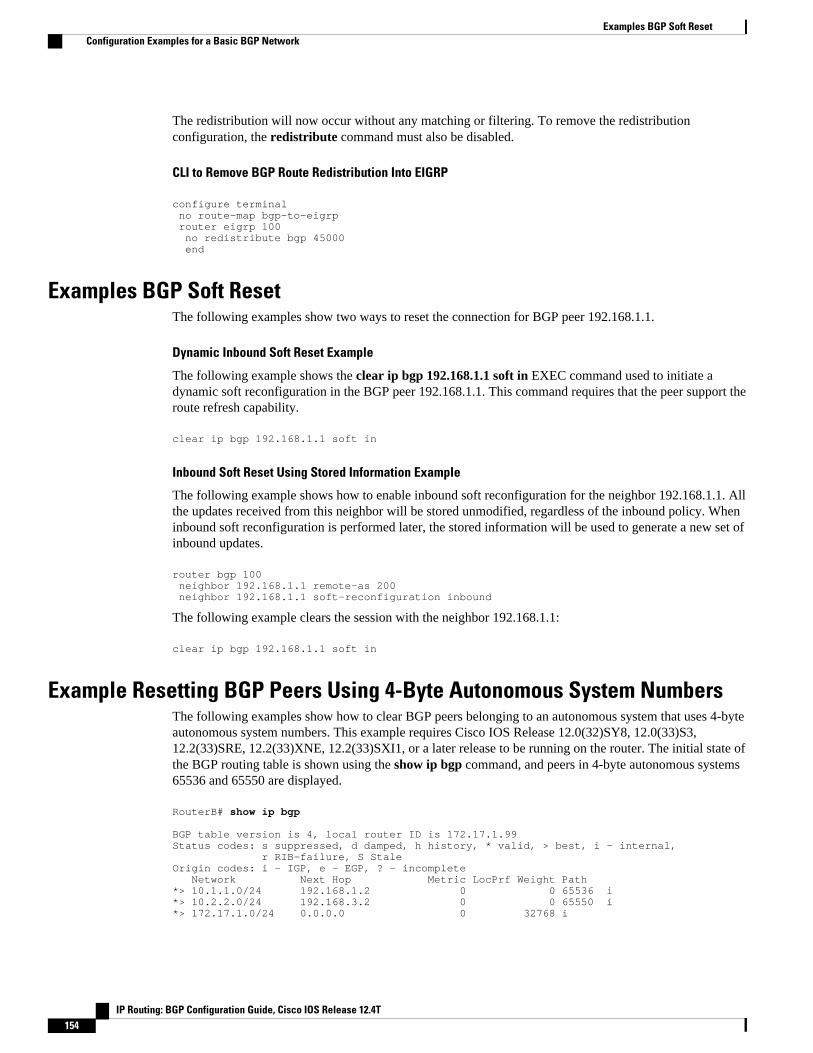
The redistribution will now occur without any matching or filtering. To remove the redistributionconfiguration, the redistribute command must also be disabled.
CLI to Remove BGP Route Redistribution Into EIGRP
configure terminal no route-map bgp-to-eigrp router eigrp 100 no redistribute bgp 45000 end
Examples BGP Soft ResetThe following examples show two ways to reset the connection for BGP peer 192.168.1.1.
Dynamic Inbound Soft Reset Example
The following example shows the clear ip bgp 192.168.1.1 soft in EXEC command used to initiate adynamic soft reconfiguration in the BGP peer 192.168.1.1. This command requires that the peer support theroute refresh capability.
clear ip bgp 192.168.1.1 soft in
Inbound Soft Reset Using Stored Information Example
The following example shows how to enable inbound soft reconfiguration for the neighbor 192.168.1.1. Allthe updates received from this neighbor will be stored unmodified, regardless of the inbound policy. Wheninbound soft reconfiguration is performed later, the stored information will be used to generate a new set ofinbound updates.
router bgp 100 neighbor 192.168.1.1 remote-as 200 neighbor 192.168.1.1 soft-reconfiguration inbound
The following example clears the session with the neighbor 192.168.1.1:
clear ip bgp 192.168.1.1 soft in
Example Resetting BGP Peers Using 4-Byte Autonomous System NumbersThe following examples show how to clear BGP peers belonging to an autonomous system that uses 4-byteautonomous system numbers. This example requires Cisco IOS Release 12.0(32)SY8, 12.0(33)S3,12.2(33)SRE, 12.2(33)XNE, 12.2(33)SXI1, or a later release to be running on the router. The initial state ofthe BGP routing table is shown using the show ip bgp command, and peers in 4-byte autonomous systems65536 and 65550 are displayed.
RouterB# show ip bgp BGP table version is 4, local router ID is 172.17.1.99Status codes: s suppressed, d damped, h history, * valid, > best, i - internal, r RIB-failure, S StaleOrigin codes: i - IGP, e - EGP, ? - incomplete Network Next Hop Metric LocPrf Weight Path*> 10.1.1.0/24 192.168.1.2 0 0 65536 i*> 10.2.2.0/24 192.168.3.2 0 0 65550 i*> 172.17.1.0/24 0.0.0.0 0 32768 i
Examples BGP Soft Reset Configuration Examples for a Basic BGP Network
IP Routing: BGP Configuration Guide, Cisco IOS Release 12.4T154
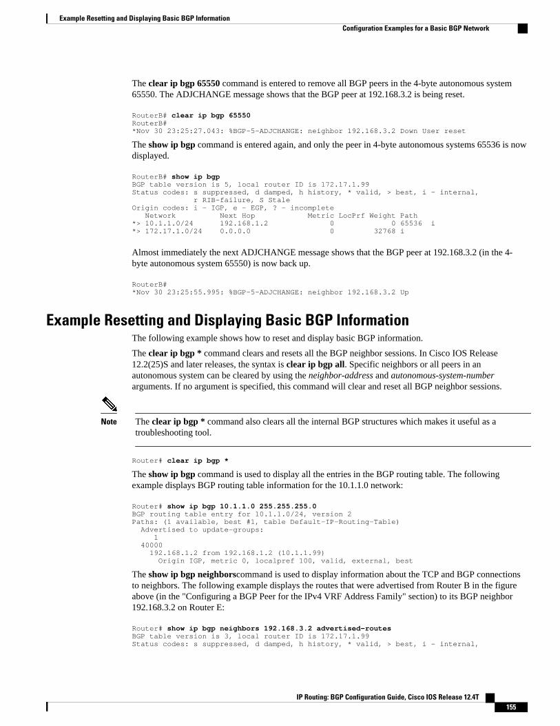
The clear ip bgp 65550 command is entered to remove all BGP peers in the 4-byte autonomous system65550. The ADJCHANGE message shows that the BGP peer at 192.168.3.2 is being reset.
RouterB# clear ip bgp 65550RouterB#*Nov 30 23:25:27.043: %BGP-5-ADJCHANGE: neighbor 192.168.3.2 Down User reset
The show ip bgp command is entered again, and only the peer in 4-byte autonomous systems 65536 is nowdisplayed.
RouterB# show ip bgpBGP table version is 5, local router ID is 172.17.1.99Status codes: s suppressed, d damped, h history, * valid, > best, i - internal, r RIB-failure, S StaleOrigin codes: i - IGP, e - EGP, ? - incomplete Network Next Hop Metric LocPrf Weight Path*> 10.1.1.0/24 192.168.1.2 0 0 65536 i*> 172.17.1.0/24 0.0.0.0 0 32768 i
Almost immediately the next ADJCHANGE message shows that the BGP peer at 192.168.3.2 (in the 4-byte autonomous system 65550) is now back up.
RouterB#*Nov 30 23:25:55.995: %BGP-5-ADJCHANGE: neighbor 192.168.3.2 Up
Example Resetting and Displaying Basic BGP InformationThe following example shows how to reset and display basic BGP information.
The clear ip bgp * command clears and resets all the BGP neighbor sessions. In Cisco IOS Release12.2(25)S and later releases, the syntax is clear ip bgp all. Specific neighbors or all peers in anautonomous system can be cleared by using the neighbor-address and autonomous-system-numberarguments. If no argument is specified, this command will clear and reset all BGP neighbor sessions.
Note The clear ip bgp * command also clears all the internal BGP structures which makes it useful as atroubleshooting tool.
Router# clear ip bgp *
The show ip bgp command is used to display all the entries in the BGP routing table. The followingexample displays BGP routing table information for the 10.1.1.0 network:
Router# show ip bgp 10.1.1.0 255.255.255.0BGP routing table entry for 10.1.1.0/24, version 2Paths: (1 available, best #1, table Default-IP-Routing-Table) Advertised to update-groups: 1 40000 192.168.1.2 from 192.168.1.2 (10.1.1.99) Origin IGP, metric 0, localpref 100, valid, external, best
The show ip bgp neighborscommand is used to display information about the TCP and BGP connectionsto neighbors. The following example displays the routes that were advertised from Router B in the figureabove (in the "Configuring a BGP Peer for the IPv4 VRF Address Family" section) to its BGP neighbor192.168.3.2 on Router E:
Router# show ip bgp neighbors 192.168.3.2 advertised-routesBGP table version is 3, local router ID is 172.17.1.99Status codes: s suppressed, d damped, h history, * valid, > best, i - internal,
Example Resetting and Displaying Basic BGP InformationConfiguration Examples for a Basic BGP Network
IP Routing: BGP Configuration Guide, Cisco IOS Release 12.4T 155

r RIB-failure, S StaleOrigin codes: i - IGP, e - EGP, ? - incomplete Network Next Hop Metric LocPrf Weight Path*> 10.1.1.0/24 192.168.1.2 0 0 40000 i*> 172.17.1.0/24 0.0.0.0 0 32768 iTotal number of prefixes 2
The show ip bgp pathscommand is used to display all the BGP paths in the database. The followingexample displays BGP path information for Router B in the figure above (in the "Customizing a BGP Peer"section):
Router# show ip bgp pathsAddress Hash Refcount Metric Path0x2FB5DB0 0 5 0 i0x2FB5C90 1 4 0 i0x2FB5C00 1361 2 0 50000 i0x2FB5D20 2625 2 0 40000 i
The show ip bgp summarycommand is used to display the status of all BGP connections. The followingexample displays BGP routing table information for Router B in the figure above (in the "Customizing aBGP Peer" section:
Router# show ip bgp summaryBGP router identifier 172.17.1.99, local AS number 45000BGP table version is 3, main routing table version 32 network entries using 234 bytes of memory2 path entries using 104 bytes of memory4/2 BGP path/bestpath attribute entries using 496 bytes of memory2 BGP AS-PATH entries using 48 bytes of memory0 BGP route-map cache entries using 0 bytes of memory0 BGP filter-list cache entries using 0 bytes of memoryBGP using 882 total bytes of memoryBGP activity 14/10 prefixes, 16/12 paths, scan interval 60 secsNeighbor V AS MsgRcvd MsgSent TblVer InQ OutQ Up/Down State/PfxRcd192.168.1.2 4 40000 667 672 3 0 0 00:03:49 1192.168.3.2 4 50000 468 467 0 0 0 00:03:49 (NoNeg)
Examples Aggregating Prefixes Using BGPThe following examples show how you can use aggregate routes in BGP either by redistributing anaggregate route into BGP or by using the BGP conditional aggregation routing feature.
In the following example, the redistribute staticrouter configuration command is used to redistributeaggregate route 10.0.0.0:
ip route 10.0.0.0 255.0.0.0 null 0!router bgp 100 redistribute static
The following configuration shows how to create an aggregate entry in the BGP routing table when at leastone specific route falls into the specified range. The aggregate route will be advertised as coming from yourautonomous system and has the atomic aggregate attribute set to show that information might be missing.(By default, atomic aggregate is set unless you use the as-set keyword in the aggregate-addressrouterconfiguration command.)
router bgp 100 aggregate-address 10.0.0.0 255.0.0.0
Examples Aggregating Prefixes Using BGP Configuration Examples for a Basic BGP Network
IP Routing: BGP Configuration Guide, Cisco IOS Release 12.4T156

The following example shows how to create an aggregate entry using the same rules as in the previousexample, but the path advertised for this route will be an AS-SET consisting of all elements contained in allpaths that are being summarized:
router bgp 100 aggregate-address 10.0.0.0 255.0.0.0 as-set
The following example shows how to create the aggregate route for 10.0.0.0 and also suppressadvertisements of more specific routes to all neighbors:
router bgp 100 aggregate-address 10.0.0.0 255.0.0.0 summary-only
The following example, starting in global configuration mode, configures BGP to not advertise inactiveroutes:
Router(config)# router bgp 50000Router(config-router)# address-family ipv4 unicastRouter(config-router-af)# bgp suppress-inactive Router(config-router-af)# end
The following example configures a maximum route limit in the VRF named red and configures BGP tonot advertise inactive routes through the VRF named RED:
Router(config)# ip vrf RED Router(config-vrf)# rd 50000:10Router(config-vrf)# maximum routes 1000 10 Router(config-vrf)# exitRouter(config)# router bgp 50000Router(config-router)# address-family ipv4 vrf REDRouter(config-router-af)# bgp suppress-inactive Router(config-router-af)# end
Example Configuring a BGP Peer GroupThe following example shows how to use an address family to configure a peer group so that all membersof the peer group are both unicast- and multicast-capable:
router bgp 45000neighbor 192.168.1.2 remote-as 40000neighbor 192.168.3.2 remote-as 50000address-family ipv4 unicast neighbor mygroup peer-group neighbor 192.168.1.2 peer-group mygroup neighbor 192.168.3.2 peer-group mygrouprouter bgp 45000neighbor 192.168.1.2 remote-as 40000neighbor 192.168.3.2 remote-as 50000address-family ipv4 multicast neighbor mygroup peer-group neighbor 192.168.1.2 peer-group mygroup neighbor 192.168.3.2 peer-group mygroup neighbor 192.168.1.2 activate neighbor 192.168.3.2 activate
Example Configuring a BGP Peer GroupConfiguration Examples for a Basic BGP Network
IP Routing: BGP Configuration Guide, Cisco IOS Release 12.4T 157

Example Configuring Peer Session TemplatesThe following example creates a peer session template named INTERNAL-BGP in session-templateconfiguration mode:
router bgp 45000 template peer-session INTERNAL-BGP remote-as 50000 timers 30 300 exit-peer-session
The following example creates a peer session template named CORE1. This example inherits theconfiguration of the peer session template named INTERNAL-BGP.
router bgp 45000 template peer-session CORE1 description CORE-123 update-source loopback 1 inherit peer-session INTERNAL-BGP exit-peer-session
The following example configures the 192.168.3.2 neighbor to inherit the CORE1 peer session template.The 192.168.3.2 neighbor will also indirectly inherit the configuration from the peer session templatenamed INTERNAL-BGP. The explicit remote-as statement is required for the neighbor inherit statementto work. If a peering is not configured, the specified neighbor will not accept the session template.
router bgp 45000 neighbor 192.168.3.2 remote-as 50000 neighbor 192.168.3.2 inherit peer-session CORE1
Example Configuring Peer Policy TemplatesThe following example creates a peer policy template named GLOBAL in policy-template configurationmode:
router bgp 45000 template peer-policy GLOBAL weight 1000 maximum-prefix 5000 prefix-list NO_SALES in exit-peer-policy
The following example creates a peer policy template named PRIMARY-IN in policy-templateconfiguration mode:
template peer-policy PRIMARY-IN prefix-list ALLOW-PRIMARY-A in route-map SET-LOCAL in weight 2345 default-originate exit-peer-policy
The following example creates a peer policy template named CUSTOMER-A. This peer policy template isconfigured to inherit the configuration from the peer policy templates named PRIMARY-IN and GLOBAL.
template peer-policy CUSTOMER-A route-map SET-COMMUNITY in filter-list 20 in inherit peer-policy PRIMARY-IN 20 inherit peer-policy GLOBAL 10 exit-peer-policy
Example Configuring Peer Session Templates Configuration Examples for a Basic BGP Network
IP Routing: BGP Configuration Guide, Cisco IOS Release 12.4T158
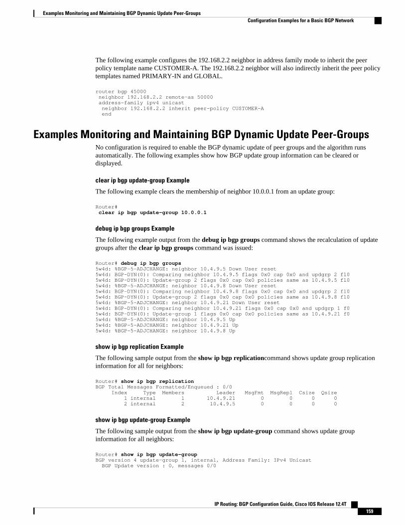
The following example configures the 192.168.2.2 neighbor in address family mode to inherit the peerpolicy template name CUSTOMER-A. The 192.168.2.2 neighbor will also indirectly inherit the peer policytemplates named PRIMARY-IN and GLOBAL.
router bgp 45000 neighbor 192.168.2.2 remote-as 50000 address-family ipv4 unicast neighbor 192.168.2.2 inherit peer-policy CUSTOMER-A end
Examples Monitoring and Maintaining BGP Dynamic Update Peer-GroupsNo configuration is required to enable the BGP dynamic update of peer groups and the algorithm runsautomatically. The following examples show how BGP update group information can be cleared ordisplayed.
clear ip bgp update-group Example
The following example clears the membership of neighbor 10.0.0.1 from an update group:
Router# clear ip bgp update-group 10.0.0.1
debug ip bgp groups Example
The following example output from the debug ip bgp groups command shows the recalculation of updategroups after the clear ip bgp groups command was issued:
Router# debug ip bgp groups 5w4d: %BGP-5-ADJCHANGE: neighbor 10.4.9.5 Down User reset5w4d: BGP-DYN(0): Comparing neighbor 10.4.9.5 flags 0x0 cap 0x0 and updgrp 2 fl05w4d: BGP-DYN(0): Update-group 2 flags 0x0 cap 0x0 policies same as 10.4.9.5 fl05w4d: %BGP-5-ADJCHANGE: neighbor 10.4.9.8 Down User reset5w4d: BGP-DYN(0): Comparing neighbor 10.4.9.8 flags 0x0 cap 0x0 and updgrp 2 fl05w4d: BGP-DYN(0): Update-group 2 flags 0x0 cap 0x0 policies same as 10.4.9.8 fl05w4d: %BGP-5-ADJCHANGE: neighbor 10.4.9.21 Down User reset5w4d: BGP-DYN(0): Comparing neighbor 10.4.9.21 flags 0x0 cap 0x0 and updgrp 1 f05w4d: BGP-DYN(0): Update-group 1 flags 0x0 cap 0x0 policies same as 10.4.9.21 f05w4d: %BGP-5-ADJCHANGE: neighbor 10.4.9.5 Up 5w4d: %BGP-5-ADJCHANGE: neighbor 10.4.9.21 Up 5w4d: %BGP-5-ADJCHANGE: neighbor 10.4.9.8 Up
show ip bgp replication Example
The following sample output from the show ip bgp replicationcommand shows update group replicationinformation for all for neighbors:
Router# show ip bgp replication BGP Total Messages Formatted/Enqueued : 0/0 Index Type Members Leader MsgFmt MsgRepl Csize Qsize 1 internal 1 10.4.9.21 0 0 0 0 2 internal 2 10.4.9.5 0 0 0 0
show ip bgp update-group Example
The following sample output from the show ip bgp update-group command shows update groupinformation for all neighbors:
Router# show ip bgp update-groupBGP version 4 update-group 1, internal, Address Family: IPv4 Unicast BGP Update version : 0, messages 0/0
Examples Monitoring and Maintaining BGP Dynamic Update Peer-GroupsConfiguration Examples for a Basic BGP Network
IP Routing: BGP Configuration Guide, Cisco IOS Release 12.4T 159
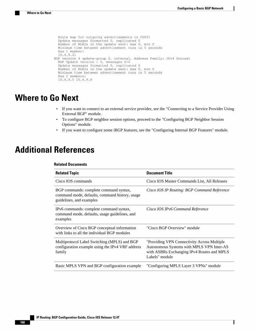
Route map for outgoing advertisements is COST1 Update messages formatted 0, replicated 0 Number of NLRIs in the update sent: max 0, min 0 Minimum time between advertisement runs is 5 seconds Has 1 member: 10.4.9.21 BGP version 4 update-group 2, internal, Address Family: IPv4 Unicast BGP Update version : 0, messages 0/0 Update messages formatted 0, replicated 0 Number of NLRIs in the update sent: max 0, min 0 Minimum time between advertisement runs is 5 seconds Has 2 members: 10.4.9.5 10.4.9.8
Where to Go Next• If you want to connect to an external service provider, see the "Connecting to a Service Provider Using
External BGP" module.• To configure BGP neighbor session options, proceed to the "Configuring BGP Neighbor Session
Options" module.• If you want to configure some iBGP features, see the "Configuring Internal BGP Features" module.
Additional ReferencesRelated Documents
Related Topic Document Title
Cisco IOS commands Cisco IOS Master Commands List, All Releases
BGP commands: complete command syntax,command mode, defaults, command history, usageguidelines, and examples
Cisco IOS IP Routing: BGP Command Reference
IPv6 commands: complete command syntax,command mode, defaults, usage guidelines, andexamples
Cisco IOS IPv6 Command Reference
Overview of Cisco BGP conceptual informationwith links to all the individual BGP modules
"Cisco BGP Overview" module
Multiprotocol Label Switching (MPLS) and BGPconfiguration example using the IPv4 VRF addressfamily
"Providing VPN Connectivity Across MultipleAutonomous Systems with MPLS VPN Inter-ASwith ASBRs Exchanging IPv4 Routes and MPLSLabels" module
Basic MPLS VPN and BGP configuration example "Configuring MPLS Layer 3 VPNs" module
Configuring a Basic BGP Network Where to Go Next
IP Routing: BGP Configuration Guide, Cisco IOS Release 12.4T160

Standards
Standard Title
MDT SAFI MDT SAFI
MIBs
MIB MIBs Link
CISCO-BGP4-MIB To locate and download MIBs for selectedplatforms, Cisco IOS releases, and feature sets, useCisco MIB Locator found at the following URL:
http://www.cisco.com/go/mibs
RFCs
RFC Title
RFC 1772 Application of the Border Gateway Protocol in theInternet
RFC 1773 Experience with the BGP Protocol
RFC 1774 BGP-4 Protocol Analysis
RFC 1930 Guidelines for Creation, Selection, andRegistration of an Autonomous System (AS)
RFC 2519 A Framework for Inter-Domain Route Aggregation
RFC 2858 Multiprotocol Extensions for BGP-4
RFC 2918 Route Refresh Capability for BGP-4
RFC 3392 Capabilities Advertisement with BGP-4
RFC 4271 A Border Gateway Protocol 4 (BGP-4)
RFC 4893 BGP Support for Four-octet AS Number Space
RFC 5396 Textual Representation of Autonomous system(AS) Numbers
RFC 5398 Autonomous System (AS) Number Reservation forDocumentation Use
Configuring a Basic BGP NetworkAdditional References
IP Routing: BGP Configuration Guide, Cisco IOS Release 12.4T 161
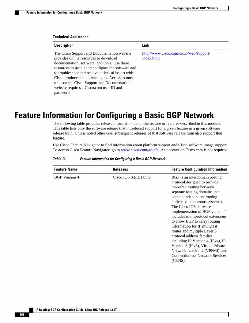
Technical Assistance
Description Link
The Cisco Support and Documentation websiteprovides online resources to downloaddocumentation, software, and tools. Use theseresources to install and configure the software andto troubleshoot and resolve technical issues withCisco products and technologies. Access to mosttools on the Cisco Support and Documentationwebsite requires a Cisco.com user ID andpassword.
http://www.cisco.com/cisco/web/support/index.html
Feature Information for Configuring a Basic BGP NetworkThe following table provides release information about the feature or features described in this module.This table lists only the software release that introduced support for a given feature in a given softwarerelease train. Unless noted otherwise, subsequent releases of that software release train also support thatfeature.
Use Cisco Feature Navigator to find information about platform support and Cisco software image support.To access Cisco Feature Navigator, go to www.cisco.com/go/cfn. An account on Cisco.com is not required.
Table 12 Feature Information for Configuring a Basic BGP Network
Feature Name Releases Feature Configuration Information
BGP Version 4 Cisco IOS XE 3.1.0SG BGP is an interdomain routingprotocol designed to provideloop-free routing betweenseparate routing domains thatcontain independent routingpolicies (autonomous systems).The Cisco IOS softwareimplementation of BGP version 4includes multiprotocol extensionsto allow BGP to carry routinginformation for IP multicastroutes and multiple Layer 3protocol address familiesincluding IP Version 4 (IPv4), IPVersion 6 (IPv6), Virtual PrivateNetworks version 4 (VPNv4), andConnectionless Network Services(CLNS).
Configuring a Basic BGP Network Feature Information for Configuring a Basic BGP Network
IP Routing: BGP Configuration Guide, Cisco IOS Release 12.4T162

Feature Name Releases Feature Configuration Information
BGP Conditional Route Injection 12.0(22)S
12.2(4)T
12.2(14)S
15.0(1)S
Cisco IOS XE 3.1.0SG
The BGP Conditional RouteInjection feature allows you toinject more specific prefixes intoa BGP routing table over lessspecific prefixes that wereselected through normal routeaggregation. These more specificprefixes can be used to provide afiner granularity of trafficengineering or administrativecontrol than is possible withaggregated routes.
BGP Configuration Using PeerTemplates
12.0(24)S
12.2(18)S
12.2(27)SBC
12.3(4)T
15.0(1)S
The BGP Configuration UsingPeer Templates feature introducesa new mechanism that groupsdistinct neighbor configurationsfor BGP neighbors that sharepolicies. This type of policyconfiguration has beentraditionally configured with BGPpeer groups. However, peergroups have certain limitationsbecause peer group configurationis bound to update grouping andspecific session characteristics.Configuration templates providean alternative to peer groupconfiguration and overcome someof the limitations of peer groups.
Configuring a Basic BGP NetworkFeature Information for Configuring a Basic BGP Network
IP Routing: BGP Configuration Guide, Cisco IOS Release 12.4T 163

Feature Name Releases Feature Configuration Information
BGP Dynamic Update PeerGroups
12.0(24)S
12.2(18)S
12.2(27)SBC
12.3(4)T
15.0(1)S
Cisco IOS XE 3.1.0SG
The BGP Dynamic Update PeerGroups feature introduces a newalgorithm that dynamicallycalculates and optimizes updategroups of neighbors that share thesame outbound policies and canshare the same update messages.In previous versions of Cisco IOSsoftware, BGP update messageswere grouped based on peer-group configurations. Thismethod of grouping updateslimited outbound policies andspecific-session configurations.The BGP Dynamic Update PeerGroup feature separates updategroup replication from peer groupconfiguration, which improvesconvergence time and flexibilityof neighbor configuration.
BGP Hybrid CLI 12.0(22)S
12.2(15)T
15.0(1)S
The BGP Hybrid CLI featuresimplifies the migration of BGPnetworks and existingconfigurations from the NLRIformat to the AFI format. Thisnew functionality allows thenetwork operator to configurecommands in the AFI format andsave these commandconfigurations to existing NLRIformatted configurations. Thefeature provides the networkoperator with the capability totake advantage of new featuresand provides support formigration from the NLRI formatto the AFI format.
Configuring a Basic BGP Network Feature Information for Configuring a Basic BGP Network
IP Routing: BGP Configuration Guide, Cisco IOS Release 12.4T164

Feature Name Releases Feature Configuration Information
BGP Neighbor Policy 12.2(33)SB
12.2(33)SRB
12.4(11)T
Cisco IOS XE 3.1.0SG
15.0(1)SY
The BGP Neighbor Policy featureintroduces new keywords to twoexisting commands to displayinformation about local andinherited policies. When BGPneighbors use multiple levels ofpeer templates, it can be difficultto determine which policies areapplied to the neighbor. Inheritedpolicies are policies that theneighbor inherits from a peer-group or a peer-policy template.
The following commands weremodified by this feature: show ipbgp neighbors, show ip bgptemplate peer-policy.
Configuring a Basic BGP NetworkFeature Information for Configuring a Basic BGP Network
IP Routing: BGP Configuration Guide, Cisco IOS Release 12.4T 165
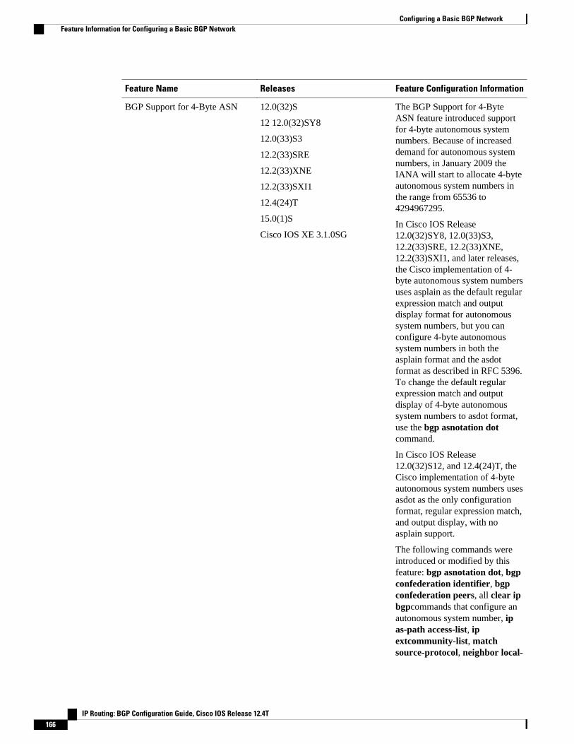
Feature Name Releases Feature Configuration Information
BGP Support for 4-Byte ASN 12.0(32)S
12 12.0(32)SY8
12.0(33)S3
12.2(33)SRE
12.2(33)XNE
12.2(33)SXI1
12.4(24)T
15.0(1)S
Cisco IOS XE 3.1.0SG
The BGP Support for 4-ByteASN feature introduced supportfor 4-byte autonomous systemnumbers. Because of increaseddemand for autonomous systemnumbers, in January 2009 theIANA will start to allocate 4-byteautonomous system numbers inthe range from 65536 to4294967295.
In Cisco IOS Release12.0(32)SY8, 12.0(33)S3,12.2(33)SRE, 12.2(33)XNE,12.2(33)SXI1, and later releases,the Cisco implementation of 4-byte autonomous system numbersuses asplain as the default regularexpression match and outputdisplay format for autonomoussystem numbers, but you canconfigure 4-byte autonomoussystem numbers in both theasplain format and the asdotformat as described in RFC 5396.To change the default regularexpression match and outputdisplay of 4-byte autonomoussystem numbers to asdot format,use the bgp asnotation dotcommand.
In Cisco IOS Release12.0(32)S12, and 12.4(24)T, theCisco implementation of 4-byteautonomous system numbers usesasdot as the only configurationformat, regular expression match,and output display, with noasplain support.
The following commands wereintroduced or modified by thisfeature: bgp asnotation dot, bgpconfederation identifier, bgpconfederation peers, all clear ipbgpcommands that configure anautonomous system number, ipas-path access-list, ipextcommunity-list, matchsource-protocol, neighbor local-
Configuring a Basic BGP Network Feature Information for Configuring a Basic BGP Network
IP Routing: BGP Configuration Guide, Cisco IOS Release 12.4T166

Feature Name Releases Feature Configuration Information
as, neighbor remote-as,neighbor soo, redistribute (IP),router bgp, route-target, set as-path, set extcommunity, setorigin, soo, all show ip bgpcommands that display anautonomous system number, andshow ip extcommunity-list.
Suppress BGP Advertisement forInactive Routes
12.2(25)S
12.2(33)SXH
15.0(1)M
15.0(1)S
The Suppress BGPAdvertisements for InactiveRoutes feature allows you toconfigure the suppression ofadvertisements for routes that arenot installed in the RoutingInformation Base (RIB).Configuring this feature allowsBorder Gateway Protocol (BGP)updates to be more consistentwith data used for trafficforwarding.
Cisco and the Cisco logo are trademarks or registered trademarks of Cisco and/or its affiliates in the U.S.and other countries. To view a list of Cisco trademarks, go to this URL: www.cisco.com/go/trademarks.Third-party trademarks mentioned are the property of their respective owners. The use of the word partnerdoes not imply a partnership relationship between Cisco and any other company. (1110R)
Any Internet Protocol (IP) addresses and phone numbers used in this document are not intended to beactual addresses and phone numbers. Any examples, command display output, network topology diagrams,and other figures included in the document are shown for illustrative purposes only. Any use of actual IPaddresses or phone numbers in illustrative content is unintentional and coincidental.
Configuring a Basic BGP Network
IP Routing: BGP Configuration Guide, Cisco IOS Release 12.4T 167

Examples Monitoring and Maintaining BGP Dynamic Update Peer-Groups
IP Routing: BGP Configuration Guide, Cisco IOS Release 12.4T168

Connecting to a Service Provider UsingExternal BGP
This module describes configuration tasks that will enable your Border Gateway Protocol (BGP) networkto access peer devices in external networks such as those from Internet service providers (ISPs). BGP isan interdomain routing protocol that is designed to provide loop-free routing between organizations.External BGP (eBGP) peering sessions are configured to allow peers from different autonomous systemsto exchange routing updates. Tasks to help manage the traffic that is flowing inbound and outbound aredescribed, as are tasks to configure BGP policies to filter the traffic. Multihoming techniques that provideredundancy for connections to a service provider are also described.
• Finding Feature Information, page 169• Prerequisites for Connecting to a Service Provider Using External BGP, page 169• Restrictions for Connecting to a Service Provider Using External BGP, page 170• Information About Connecting to a Service Provider Using External BGP, page 170• How to Connect to a Service Provider Using External BGP, page 182• Configuration Examples for Connecting to a Service Provider Using External BGP, page 240• Where to Go Next, page 251• Additional References, page 252• Feature Information for Connecting to a Service Provider Using External BGP, page 253
Finding Feature InformationYour software release may not support all the features documented in this module. For the latest featureinformation and caveats, see the release notes for your platform and software release. To find informationabout the features documented in this module, and to see a list of the releases in which each feature issupported, see the Feature Information Table at the end of this document.
Use Cisco Feature Navigator to find information about platform support and Cisco software image support.To access Cisco Feature Navigator, go to www.cisco.com/go/cfn. An account on Cisco.com is not required.
Prerequisites for Connecting to a Service Provider UsingExternal BGP
• Before connecting to a service provider you need to understand how to configure the basic BGPprocess and peers. See the "Cisco BGP Overview" and "Configuring a Basic BGP Network" modulesfor more details.
IP Routing: BGP Configuration Guide, Cisco IOS Release 12.4T 169

• The tasks and concepts in this chapter will help you configure BGP features that would be useful ifyou are connecting your network to a service provider. For each connection to the Internet, you musthave an assigned autonomous system number from the Internet Assigned Numbers Authority (IANA).
Restrictions for Connecting to a Service Provider UsingExternal BGP
• A router that runs Cisco IOS software can be configured to run only one BGP routing process and tobe a member of only one BGP autonomous system. However, a BGP routing process and autonomoussystem can support multiple address family configurations.
• Policy lists are not supported in versions of Cisco IOS software prior to Cisco IOS Release 12.0(22)Sand 12.2(15)T. Reloading a router that is running an older version of Cisco IOS software may causesome routing policy configurations to be lost.
Information About Connecting to a Service Provider UsingExternal BGP
• External BGP Peering, page 170• BGP Autonomous System Number Formats, page 172• BGP Attributes, page 174• Multihoming, page 175• MED Attribute, page 176• Transit Versus Nontransit Traffic, page 176• BGP Policy Configuration, page 176• BGP Prefix-Based Outbound Route Filtering, page 177• BGP Communities, page 178• Extended Communities, page 178• Extended Community Lists, page 179• Administrative Distance, page 180• BGP Route Map Policy Lists, page 180• BGP Route Map with a Continue Clause, page 180
External BGP PeeringBGP is an interdomain routing protocol designed to provide loop-free routing links between organizations.BGP is designed to run over a reliable transport protocol and it uses TCP (port 179) as the transportprotocol. The destination TCP port is assigned 179, and the local port is assigned a random port number.Cisco IOS software supports BGP version 4, which has been used by ISPs to help build the Internet. RFC1771 introduced and discussed a number of new BGP features to allow the protocol to scale for Internetuse.
External BGP peering sessions are configured to allow BGP peers from different autonomous systems toexchange routing updates. By design, a BGP routing process expects eBGP peers to be directly connected,for example, over a WAN connection. However, there are many real-world scenarios where this rule would
External BGP Peering Restrictions for Connecting to a Service Provider Using External BGP
IP Routing: BGP Configuration Guide, Cisco IOS Release 12.4T170

prevent routing from occurring. Peering sessions for multihop neighbors are configured with the neighborebgp-multihop command. The figure below shows simple eBGP peering between three routers. Router Bpeers with Router A and Router E. In the figure below, the neighbor ebgp-multihop command could beused to establish peering between Router A and Router E although this is a very simple network design.BGP forwards information about the next hop in the network using the NEXT_HOP attribute, which is setto the IP address of the interface that advertises a route in an eBGP peering session by default. The sourceinterface can be a physical interface or a loopback interface.
Figure 15 BGP Peers in Different Autonomous Systems
Loopback interfaces are preferred for establishing eBGP peering sessions because loopback interfaces areless susceptible to interface flapping. Interfaces on networking devices can fail, and they can also be takenout of service for maintenance. When an interface is administratively brought up or down, due to failure ormaintenance, it is referred to as a flap. Loopback interfaces provide a stable source interface to ensure thatthe IP address assigned to the interface is always reachable as long as the IP routing protocols continue toadvertise the subnet assigned to the loopback interface. Loopback interfaces allow you to conserve addressspace by configuring a single address with /32 bit mask. Before a loopback interface is configured for aneBGP peering session, you must configure the neighbor update-source command and specify theloopback interface. With this configuration, the loopback interface becomes the source interface and its IPaddress is advertised as the next hop for routes that are advertised through this loopback. If loopbackinterfaces are used to connect single-hop eBGP peers, you must configure the neighbor disable-connected-check command before you can establish the eBGP peering session.
Connecting to external networks enables traffic from your network to be forwarded to other networks andacross the Internet. Traffic will also be flowing into, and possibly through, your network. BGP containsvarious techniques to influence how the traffic flows into and out of your network, and to create BGPpolicies that filter the traffic, inbound and outbound. To influence the traffic flow, BGP uses certain BGPattributes that can be included in update messages or used by the BGP routing algorithm. BGP policies tofilter traffic also use some of the BGP attributes with route maps, access lists including AS-path accesslists, filter lists, policy lists, and distribute lists. Managing your external connections may involvemultihoming techniques where there is more than one connection to an ISP or connections to more than oneISP for backup or performance purposes. Tagging BGP routes with different community attributes acrossautonomous system or physical boundaries can prevent the need to configure long lists of individual permitor deny statements.
Connecting to a Service Provider Using External BGPInformation About Connecting to a Service Provider Using External BGP
IP Routing: BGP Configuration Guide, Cisco IOS Release 12.4T 171

BGP Autonomous System Number FormatsPrior to January 2009, BGP autonomous system numbers that were allocated to companies were 2-octetnumbers in the range from 1 to 65535 as described in RFC 4271, A Border Gateway Protocol 4 (BGP-4).Due to increased demand for autonomous system numbers, the Internet Assigned Number Authority(IANA) will start in January 2009 to allocate four-octet autonomous system numbers in the range from65536 to 4294967295. RFC 5396, Textual Representation of Autonomous System (AS) Numbers ,documents three methods of representing autonomous system numbers. Cisco has implemented thefollowing two methods:
• Asplain--Decimal value notation where both 2-byte and 4-byte autonomous system numbers arerepresented by their decimal value. For example, 65526 is a 2-byte autonomous system number and234567 is a 4-byte autonomous system number.
• Asdot--Autonomous system dot notation where 2-byte autonomous system numbers are represented bytheir decimal value and 4-byte autonomous system numbers are represented by a dot notation. Forexample, 65526 is a 2-byte autonomous system number and 1.169031 is a 4-byte autonomous systemnumber (this is dot notation for the 234567 decimal number).
For details about the third method of representing autonomous system numbers, see RFC 5396.
Asdot Only Autonomous System Number Formatting
In Cisco IOS Release 12.0(32)S12, 12.4(24)T, and later releases, the 4-octet (4-byte) autonomous systemnumbers are entered and displayed only in asdot notation, for example, 1.10 or 45000.64000. When usingregular expressions to match 4-byte autonomous system numbers the asdot format includes a period whichis a special character in regular expressions. A backslash must be entered before the period for example, 1\.14, to ensure the regular expression match does not fail. The table below shows the format in which 2-byteand 4-byte autonomous system numbers are configured, matched in regular expressions, and displayed inshow command output in Cisco IOS images where only asdot formatting is available.
Table 13 Asdot Only 4-Byte Autonomous System Number Format
Format Configuration Format Show Command Output andRegular Expression MatchFormat
asdot 2-byte: 1 to 65535 4-byte: 1.0 to65535.65535
2-byte: 1 to 65535 4-byte: 1.0 to65535.65535
Asplain as Default Autonomous System Number Formatting
In Cisco IOS Release 12.0(32)SY8, 12.0(33)S3, 12.2(33)SRE, 12.2(33)XNE, 12.2(33)SXI1, and laterreleases, the Cisco implementation of 4-byte autonomous system numbers uses asplain as the defaultdisplay format for autonomous system numbers, but you can configure 4-byte autonomous system numbersin both the asplain and asdot format. In addition, the default format for matching 4-byte autonomoussystem numbers in regular expressions is asplain, so you must ensure that any regular expressions to match4-byte autonomous system numbers are written in the asplain format. If you want to change the defaultshow command output to display 4-byte autonomous system numbers in the asdot format, use the bgpasnotation dot command under router configuration mode. When the asdot format is enabled as thedefault, any regular expressions to match 4-byte autonomous system numbers must be written using theasdot format, or the regular expression match will fail. The tables below show that although you canconfigure 4-byte autonomous system numbers in either asplain or asdot format, only one format is used todisplay show command output and control 4-byte autonomous system number matching for regular
BGP Autonomous System Number Formats Information About Connecting to a Service Provider Using External BGP
IP Routing: BGP Configuration Guide, Cisco IOS Release 12.4T172

expressions, and the default is asplain format. To display 4-byte autonomous system numbers in showcommand output and to control matching for regular expressions in the asdot format, you must configurethe bgp asnotation dot command. After enabling the bgp asnotation dot command, a hard reset must beinitiated for all BGP sessions by entering the clear ip bgp * command.
Note If you are upgrading to an image that supports 4-byte autonomous system numbers, you can still use 2-byteautonomous system numbers. The show command output and regular expression match are not changedand remain in asplain (decimal value) format for 2-byte autonomous system numbers regardless of theformat configured for 4-byte autonomous system numbers.
Table 14 Default Asplain 4-Byte Autonomous System Number Format
Format Configuration Format Show Command Output andRegular Expression MatchFormat
asplain 2-byte: 1 to 65535 4-byte: 65536to 4294967295
2-byte: 1 to 65535 4-byte: 65536to 4294967295
asdot 2-byte: 1 to 65535 4-byte: 1.0 to65535.65535
2-byte: 1 to 65535 4-byte: 65536to 4294967295
Table 15 Asdot 4-Byte Autonomous System Number Format
Format Configuration Format Show Command Output andRegular Expression MatchFormat
asplain 2-byte: 1 to 65535 4-byte: 65536to 4294967295
2-byte: 1 to 65535 4-byte: 1.0 to65535.65535
asdot 2-byte: 1 to 65535 4-byte: 1.0 to65535.65535
2-byte: 1 to 65535 4-byte: 1.0 to65535.65535
Reserved and Private Autonomous System Numbers
In Cisco IOS Release 12.0(32)S12, 12.0(32)SY8, 12.0(33)S3, 12.2(33)SRE, 12.2(33)XNE, 12.2(33)SXI1,12.4(24)T, and later releases, the Cisco implementation of BGP supports RFC 4893. RFC 4893 wasdeveloped to allow BGP to support a gradual transition from 2-byte autonomous system numbers to 4-byteautonomous system numbers. A new reserved (private) autonomous system number, 23456, was created byRFC 4893 and this number cannot be configured as an autonomous system number in the Cisco IOS CLI.
RFC 5398, Autonomous System (AS) Number Reservation for Documentation Use, describes new reservedautonomous system numbers for documentation purposes. Use of the reserved numbers allow configurationexamples to be accurately documented and avoids conflict with production networks if these configurationsare literally copied. The reserved numbers are documented in the IANA autonomous system numberregistry. Reserved 2-byte autonomous system numbers are in the contiguous block, 64496 to 64511 andreserved 4-byte autonomous system numbers are from 65536 to 65551 inclusive.
Private 2-byte autonomous system numbers are still valid in the range from 64512 to 65534 with 65535being reserved for special use. Private autonomous system numbers can be used for internal routingdomains but must be translated for traffic that is routed out to the Internet. BGP should not be configured to
Connecting to a Service Provider Using External BGPInformation About Connecting to a Service Provider Using External BGP
IP Routing: BGP Configuration Guide, Cisco IOS Release 12.4T 173
advertise private autonomous system numbers to external networks. Cisco IOS software does not removeprivate autonomous system numbers from routing updates by default. We recommend that ISPs filterprivate autonomous system numbers.
Note Autonomous system number assignment for public and private networks is governed by the IANA. Forinformation about autonomous-system numbers, including reserved number assignment, or to apply toregister an autonomous system number, see the following URL: http://www.iana.org/.
BGP AttributesBGP selects a single path, by default, as the best path to a destination host or network. The best-pathselection algorithm analyzes path attributes to determine which route is installed as the best path in theBGP routing table. Each path carries various attributes that are used in BGP best-path analysis. Cisco IOSsoftware provides the ability to influence BGP path selection by altering these attributes via the command-line interface (CLI). BGP path selection can also be influenced through standard BGP policy configuration.
BGP uses the best-path selection algorithm to find a set of equally good routes. These routes are thepotential multipaths. In Cisco IOS Release 12.2(33)SRD and later releases, when there are more equallygood multipaths available than the maximum permitted number, then the oldest paths are selected asmultipaths.
BGP can include path attribute information in update messages. BGP attributes describe the characteristicof the route, and the software uses these attributes to help make decisions about which routes to advertise.Some of this attribute information can be configured at a BGP-speaking networking device. There are somemandatory attributes that are always included in the update message and some discretionary attributes. Thefollowing BGP attributes can be configured:
• AS-path• Community• Local_Pref• Multi_Exit_Discriminator (MED)• Next_Hop• Origin
AS-path
This attribute contains a list or set of the autonomous system numbers through which routing informationhas passed. The BGP speaker adds its own autonomous system number to the list when it forwards theupdate message to external peers.
Community
BGP communities are used to group networking devices that share common properties, regardless ofnetwork, autonomous system, or any physical boundaries. In large networks applying a common routingpolicy through prefix lists or access lists requires individual peer statements on each networking device.Using the BGP community attribute BGP neighbors, with common routing policies, can implementinbound or outbound route filters based on the community tag rather than consult large lists of individualpermit or deny statements.
Local_Pref
Within an autonomous system, the Local_Pref attribute is included in all update messages between BGPpeers. If there are several paths to the same destination, the local preference attribute with the highest value
BGP Attributes Information About Connecting to a Service Provider Using External BGP
IP Routing: BGP Configuration Guide, Cisco IOS Release 12.4T174
indicates the preferred outbound path from the local autonomous system. The highest ranking route isadvertised to internal peers. The Local_Pref value is not forwarded to external peers.
Multi_Exit_Discriminator
The MED attribute indicates (to an external peer) a preferred path into an autonomous system. If there aremultiple entry points into an autonomous system, the MED can be used to influence another autonomoussystem to choose one particular entry point. A metric is assigned where a lower MED metric is preferred bythe software over a higher MED metric. The MED metric is exchanged between autonomous systems, butafter a MED is forwarded into an autonomous system, the MED metric is reset to the default value of 0.When an update is sent to an internal BGP (iBGP) peer, the MED is passed along without any change,allowing all the peers in the same autonomous system to make a consistent path selection.
By default, a router will compare the MED attribute for paths only from BGP peers that reside in the sameautonomous system. The bgp always-compare-med command can be configured to allow the router tocompare metrics from peers in different autonomous systems.
Note The Internet Engineering Task Force (IETF) decision regarding BGP MED assigns a value of infinity to themissing MED, making the route that lacks the MED variable the least preferred. The default behavior ofBGP routers that run Cisco IOS software is to treat routes without the MED attribute as having a MED of 0,making the route that lacks the MED variable the most preferred. To configure the router to conform to theIETF standard, use the bgp bestpath med missing-as-worstrouter configuration command.
Next_Hop
The Next_Hop attribute identifies the next-hop IP address to be used as the BGP next hop to thedestination. The router makes a recursive lookup to find the BGP next hop in the routing table. In externalBGP (eBGP), the next hop is the IP address of the peer that sent the update. Internal BGP (iBGP) sets thenext-hop address to the IP address of the peer that advertised the prefix for routes that originate internally.When any routes to iBGP that are learned from eBGP are advertised, the Next_Hop attribute is unchanged.
A BGP next-hop IP address must be reachable in order for the router to use a BGP route. Reachabilityinformation is usually provided by the IGP, and changes in the IGP can influence the forwarding of thenext-hop address over a network backbone.
Origin
This attribute indicates how the route was included in a BGP routing table. In Cisco IOS software, a routedefined using the BGP network command is given an origin code of Interior Gateway Protocol (IGP).Routes distributed from an Exterior Gateway Protocol (EGP) are coded with an origin of EGP, and routesredistributed from other protocols are defined as Incomplete. BGP decision policy for origin prefers IGPover EGP, and then EGP over Incomplete.
MultihomingMultihoming is defined as connecting an autonomous system with more than one service provider. If youhave any reliability issues with one service provider, then you have a backup connection. Performanceissues can also be addressed by multihoming because better paths to the destination network can beutilized.
Unless you are a service provider, you must plan your routing configuration carefully to avoid Internettraffic traveling through your autonomous system and consuming all your bandwidth. The figure belowshows that autonomous system 45000 is multihomed to autonomous system 40000 and autonomous system
MultihomingInformation About Connecting to a Service Provider Using External BGP
IP Routing: BGP Configuration Guide, Cisco IOS Release 12.4T 175

50000. Assuming autonomous system 45000 is not a service provider, then several techniques such as loadbalancing or some form of routing policy must be configured to allow traffic from autonomous system45000 to reach either autonomous system 40000 or autonomous system 50000 but not allow much, if any,transit traffic.
Figure 16 Multihoming Topology
MED AttributeConfiguring the MED attribute is another method that BGP can use to influence the choice of paths intoanother autonomous system. The MED attribute indicates (to an external peer) a preferred path into anautonomous system. If there are multiple entry points into an autonomous system, the MED can be used toinfluence another autonomous system to choose one particular entry point. A metric is assigned using routemaps where a lower MED metric is preferred by the software over a higher MED metric.
Transit Versus Nontransit TrafficMost of the traffic within an autonomous system contains a source or destination IP address residing withinthe autonomous system, and this traffic is referred to as nontransit (or local) traffic. Other traffic is definedas transit traffic. As traffic across the Internet increases, controlling transit traffic becomes more important.
A service provider is considered to be a transit autonomous system and must provide connectivity to allother transit providers. In reality, few service providers actually have enough bandwidth to allow all transittraffic, and most service providers have to purchase such connectivity from Tier 1 service providers.
An autonomous system that does not usually allow transit traffic is called a stub autonomous system andwill link to the Internet through one service provider.
BGP Policy ConfigurationBGP policy configuration is used to control prefix processing by the BGP routing process and to filterroutes from inbound and outbound advertisements. Prefix processing can be controlled by adjusting BGPtimers, altering how BGP handles path attributes, limiting the number of prefixes that the routing processwill accept, and configuring BGP prefix dampening. Prefixes in inbound and outbound advertisements are
MED Attribute Information About Connecting to a Service Provider Using External BGP
IP Routing: BGP Configuration Guide, Cisco IOS Release 12.4T176
filtered using route maps, filter lists, IP prefix lists, autonomous-system-path access lists, IP policy lists,and distribute lists. The table below shows the processing order of BGP policy filters.
Table 16 BGP Policy Processing Order
Inbound Outbound
Route map Distribute list
Filter list, AS-path access list, or IP policy IP prefix list
IP prefix list Filter list, AS-path access list, or IP policy
Distribute list Route map
Note In Cisco IOS Releases 12.0(22)S, 12.2(15)T, 12.2(18)S, and later releases, the maximum number ofautonomous system access lists that can be configured with the ip as-path access-list command isincreased from 199 to 500.
Whenever there is a change in the routing policy due to a configuration change, BGP peering sessions mustbe reset using the clear ip bgp command. Cisco IOS software supports the following three mechanisms toreset BGP peering sessions:
• Hard reset--A hard reset tears down the specified peering sessions, including the TCP connection, anddeletes routes coming from the specified peer.
• Soft reset--A soft reset uses stored prefix information to reconfigure and activate BGP routing tableswithout tearing down existing peering sessions. Soft reset uses stored update information, at the cost ofadditional memory for storing the updates, to allow you to apply a new BGP policy without disruptingthe network. Soft reset can be configured for inbound or outbound sessions.
• Dynamic inbound soft reset--The route refresh capability, as defined in RFC 2918, allows the localrouter to reset inbound routing tables dynamically by exchanging route refresh requests to supportingpeers. The route refresh capability does not store update information locally for nondisruptive policychanges. It instead relies on dynamic exchange with supporting peers. Route refresh must first beadvertised through BGP capability negotiation between peers. All BGP routers must support the routerefresh capability.
To determine if a BGP router supports this capability, use the show ip bgp neighborscommand. Thefollowing message is displayed in the output when the router supports the route refresh capability:
Received route refresh capability from peer.
BGP Prefix-Based Outbound Route FilteringBGP prefix-based outbound route filtering uses the BGP ORF send and receive capabilities to minimize thenumber of BGP updates that are sent between BGP peers. Configuring BGP ORF can help reduce theamount of system resources required for generating and processing routing updates by filtering outunwanted routing updates at the source. For example, BGP ORF can be used to reduce the amount ofprocessing required on a router that is not accepting full routes from a service provider network.
The BGP prefix-based outbound route filtering is enabled through the advertisement of ORF capabilities topeer routers. The advertisement of the ORF capability indicates that a BGP peer will accept a prefix listfrom a neighbor and apply the prefix list to locally configured ORFs (if any exist). When this capability is
BGP Prefix-Based Outbound Route FilteringInformation About Connecting to a Service Provider Using External BGP
IP Routing: BGP Configuration Guide, Cisco IOS Release 12.4T 177

enabled, the BGP speaker can install the inbound prefix list filter to the remote peer as an outbound filter,which reduces unwanted routing updates.
The BGP prefix-based outbound route filtering can be configured with send or receive ORF capabilities.The local peer advertises the ORF capability in send mode. The remote peer receives the ORF capability inreceive mode and applies the filter as an outbound policy. The local and remote peers exchange updates tomaintain the ORF on each router. Updates are exchanged between peer routers by address familydepending on the ORF prefix list capability that is advertised. The remote peer starts sending updates to thelocal peer after a route refresh has been requested with the clear ip bgp in prefix-filtercommand or afteran ORF prefix list with immediate status is processed. The BGP peer will continue to apply the inboundprefix list to received updates after the local peer pushes the inbound prefix list to the remote peer.
BGP CommunitiesBGP communities are used to group routes (also referred to as color routes) that share common properties,regardless of network, autonomous system, or any physical boundaries. In large networks applying acommon routing policy through prefix-lists or access-lists requires individual peer statements on eachnetworking device. Using the BGP community attribute BGP speakers, with common routing policies, canimplement inbound or outbound route filters based on the community tag rather than consult large lists ofindividual permit or deny statements.
Standard community lists are used to configure well-known communities and specific community numbers.Expanded community lists are used to filter communities using a regular expression. Regular expressionsare used to configure patterns to match community attributes.
The community attribute is optional, which means that it will not be passed on by networking devices thatdo not understand communities. Networking devices that understand communities must be configured tohandle the communities or they will be discarded.
There are four predefined communities:
• no-export--Do not advertise to external BGP peers.• no-advertise--Do not advertise this route to any peer.• internet--Advertise this route to the Internet community; all BGP-speaking networking devices belong
to it.• local-as--Do not send outside the local autonomous system.
In Cisco IOS Release 12.2(8)T, BGP named community lists were introduced. BGP named community listsallow meaningful names to be assigned to community lists with no limit on the number of community liststhat can be configured. A named community list can be configured with regular expressions and withnumbered community lists. All the rules of numbered communities apply to named community lists exceptthat there is no limitation on the number of named community lists that can be configured.
Note Both standard and expanded community lists have a limitation of 100 community groups that can beconfigured within each type of list. A named community list does not have this limitation.
Extended CommunitiesExtended community attributes are used to configure, filter, and identify routes for virtual routing andforwarding (VRF) instances and Multiprotocol Label Switching (MPLS) Virtual Private Networks (VPNs).All of the standard rules of access lists apply to the configuration of extended community lists. Regularexpressions are supported by the expanded range of extended community list numbers. All regular
BGP Communities Information About Connecting to a Service Provider Using External BGP
IP Routing: BGP Configuration Guide, Cisco IOS Release 12.4T178
expression configuration options are supported. The route target (RT) and site of origin (SoO) extendedcommunity attributes are supported by the standard range of extended community lists.
Route Target Extended Community Attribute
The RT extended community attribute is configured with the rt keyword of the ip extcommunity-listcommand. This attribute is used to identify a set of sites and VRFs that may receive routes that aretagged with the configured route target. Configuring the route target extended community attribute with aroute allows that route to be placed in the per-site forwarding tables that are used for routing traffic that isreceived from corresponding sites.
Site of Origin Extended Community Attribute
The SoO extended community attribute is configured with the soo keyword of the ip extcommunity-listcommand. This attribute uniquely identifies the site from which the provider edge (PE) router learnedthe route. All routes learned from a particular site must be assigned the same SoO extended communityattribute, regardless if a site is connected to a single PE router or multiple PE routers. Configuring thisattribute prevents routing loops from occurring when a site is multihomed. The SoO extended communityattribute is configured on the interface and is propagated into BGP through redistribution. The SoOextended community attribute can be applied to routes that are learned from VRFs. The SoO extendedcommunity attribute should not be configured for stub sites or sites that are not multihomed.
IP Extended Community-List Configuration Mode
Named and numbered extended community lists can be configured in IP extended community-listconfiguration mode. The IP extended community-list configuration mode supports all of the functions thatare available in global configuration mode. In addition, the following operations can be performed:
• Configure sequence numbers for extended community list entries.• Resequence existing sequence numbers for extended community list entries.• Configure an extended community list to use default values.
Default Sequence Numbering
Extended community list entries start with the number 10 and increment by 10 for each subsequent entrywhen no sequence number is specified, when default behavior is configured, and when an extendedcommunity list is resequenced without specifying the first entry number or the increment range forsubsequent entries.
Resequencing Extended Community Lists
Extended community-list entries are sequenced and resequenced on a per-extended community list basis.The resequence command can be used without any arguments to set all entries in a list to default sequencenumbering. The resequence command also allows the sequence number of the first entry and incrementrange to be set for each subsequent entry. The range of configurable sequence numbers is from 1 to2147483647.
Extended Community ListsExtended community attributes are used to configure, filter, and identify routes for VRF instances andMPLS VPNs. The ip extcommunity-listcommand is used to configure named or numbered extendedcommunity lists. All of the standard rules of access lists apply to the configuration of extended communitylists. Regular expressions are supported by the expanded range of extended community list numbers.
Extended Community ListsInformation About Connecting to a Service Provider Using External BGP
IP Routing: BGP Configuration Guide, Cisco IOS Release 12.4T 179

Administrative DistanceAdministrative distance is a measure of the preference of different routing protocols. BGP has a distancebgp command that allows you to set different administrative distances for three route types: external,internal, and local. BGP, like other protocols, prefers the route with the lowest administrative distance.
BGP Route Map Policy ListsBGP route map policy lists allow a network operator to group route map match clauses into named listscalled policy lists. A policy list functions like a macro. When a policy list is referenced in a route map, allof the match clauses are evaluated and processed as if they had been configured directly in the route map.This enhancement simplifies the configuration of BGP routing policy in medium-size and large networksbecause a network operator can preconfigure policy lists with groups of match clauses and then referencethese policy lists within different route maps. The network operator no longer needs to manuallyreconfigure each recurring group of match clauses that occur in multiple route map entries.
A policy lists functions like a macro when it is configured in a route map and has the following capabilitiesand characteristics:
• When a policy list is referenced within a route map, all the match statements within the policy list areevaluated and processed.
• Two or more policy lists can be configured with a route map. Policy lists can be configured within aroute map to be evaluated with AND or OR semantics.
• Policy lists can coexist with any other preexisting match and set statements that are configured withinthe same route map but outside of the policy lists.
• When multiple policy lists perform matching within a route map entry, all policy lists match on theincoming attribute only.
Policy lists support only match clauses and do not support set clauses. Policy lists can be configured for allapplications of route maps, including redistribution, and can also coexist, within the same route map entry,with match and set clauses that are configured separately from the policy lists.
Note Policy lists are supported only by BGP and are not supported by other IP routing protocols.
BGP Route Map with a Continue ClauseIn Cisco IOS Release 12.3(2)T, 12.0(24)S, 12.2(33)SRB, and later releases, the continue clause wasintroduced into BGP route map configuration. The continue clause allows for more programmable policyconfiguration and route filtering and introduced the capability to execute additional entries in a route mapafter an entry is executed with successful match and set clauses. Continue clauses allow the networkoperator to configure and organize more modular policy definitions so that specific policy configurationsneed not be repeated within the same route map. Before the continue clause was introduced, route mapconfiguration was linear and did not allow any control over the flow of a route map.
In Cisco IOS Release 12.0(31)S, 12.2(33)SB, 12.2(33)SRB, 12.2(33)SXI, 12.4(4)T, and later releases,support for continue clauses for outbound route maps was introduced.
• Route Map Operation Without Continue Clauses, page 181
• Route Map Operation with Continue Clauses, page 181
• Match Operations with Continue Clauses, page 181
Administrative Distance Information About Connecting to a Service Provider Using External BGP
IP Routing: BGP Configuration Guide, Cisco IOS Release 12.4T180

• Set Operations with Continue Clauses, page 181
Route Map Operation Without Continue ClausesA route map evaluates match clauses until a successful match occurs. After the match occurs, the route mapstops evaluating match clauses and starts executing set clauses, in the order in which they were configured.If a successful match does not occur, the route map "falls through" and evaluates the next sequence numberof the route map until all configured route map entries have been evaluated or a successful match occurs.Each route map sequence is tagged with a sequence number to identify the entry. Route map entries areevaluated in order starting with the lowest sequence number and ending with the highest sequence number.If the route map contains only set clauses, the set clauses will be executed automatically, and the route mapwill not evaluate any other route map entries.
Route Map Operation with Continue ClausesWhen a continue clause is configured, the route map will continue to evaluate and execute match clauses inthe specified route map entry after a successful match occurs. The continue clause can be configured to goto (or jump to) a specific route map entry by specifying the sequence number, or if a sequence number isnot specified, the continue clause will go to the next sequence number. This behavior is called an "impliedcontinue." If a match clause exists, the continue clause is executed only if a match occurs. If no successfulmatches occur, the continue clause is ignored.
Match Operations with Continue ClausesIf a match clause does not exist in the route map entry but a continue clause does, the continue clause willbe automatically executed and go to the specified route map entry. If a match clause exists in a route mapentry, the continue clause is executed only when a successful match occurs. When a successful matchoccurs and a continue clause exists, the route map executes the set clauses and then goes to the specifiedroute map entry. If the next route map entry contains a continue clause, the route map will execute thecontinue clause if a successful match occurs. If a continue clause does not exist in the next route map entry,the route map will be evaluated normally. If a continue clause exists in the next route map entry but amatch does not occur, the route map will not continue and will "fall through" to the next sequence numberif one exists.
Set Operations with Continue ClausesSet clauses are saved during the match clause evaluation process and executed after the route-mapevaluation is completed. The set clauses are evaluated and executed in the order in which they wereconfigured. Set clauses are executed only after a successful match occurs, unless the route map does notcontain a match clause. The continue statement proceeds to the specified route map entry only afterconfigured set actions are performed. If a set action occurs in the first route map and then the same setaction occurs again, with a different value, in a subsequent route map entry, the last set action may overrideany previous set actions that were configured with the same set command unless the set command permitsmore than one value. For example, the set as-path prepend command permits more than one autonomoussystem number to be configured.
Note A continue clause can be executed, without a successful match, if a route map entry does not contain amatch clause.
Connecting to a Service Provider Using External BGPRoute Map Operation Without Continue Clauses
IP Routing: BGP Configuration Guide, Cisco IOS Release 12.4T 181

Note Route maps have a linear behavior and not a nested behavior. Once a route is matched in a route mappermit entry with a continue command clause, it will not be processed by the implicit deny at the end of theroute-map. For an example, see "Filtering Traffic Using Continue Clauses in a BGP Route Map Examples".
• Restrictions, page 182
Restrictions
• Continue clauses for outbound route maps are supported only in Cisco IOS Release 12.0(31)S,12.2(33)SB, 12.2(33)SRB, 12.2(33)SXI, 12.4(4)T, and later releases.
• Continue clauses can go only to a higher route map entry (a route map entry with a higher sequencenumber) and cannot go to a lower route map entry.
How to Connect to a Service Provider Using External BGP• Influencing Inbound Path Selection, page 182• Influencing Outbound Path Selection, page 190• Configuring BGP Peering with ISPs, page 197• Configuring BGP Policies, page 213
Influencing Inbound Path SelectionBGP can be used to influence the choice of paths in another autonomous system. There may be severalreasons for wanting BGP to choose a path that is not the obvious best route, for example, to avoid sometypes of transit traffic passing through an autonomous system or perhaps to avoid a very slow or congestedlink. BGP can influence inbound path selection using one of the following BGP attributes:
• AS-path• MED
Perform one of the following tasks to influence inbound path selection:
• Influencing Inbound Path Selection by Modifying the AS-path Attribute, page 182• Influencing Inbound Path Selection by Setting the MED Attribute, page 187
Influencing Inbound Path Selection by Modifying the AS-path AttributePerform this task to influence the inbound path selection for traffic destined for the 172.17.1.0 network bymodifying the AS-path attribute. The configuration is performed at Router A in the figure below. For aconfiguration example of this task using 4-byte autonomous system numbers in asplain format, see Influencing Inbound Path Selection by Modifying the AS-path Attribute Using 4-Byte AS NumbersExample, page 241.
One of the methods that BGP can use to influence the choice of paths in another autonomous system is tomodify the AS-path attribute. For example, in the figure below, Router A advertises its own network,172.17.1.0, to its BGP peers in autonomous system 45000 and autonomous system 60000. When therouting information is propagated to autonomous system 50000, the routers in autonomous system 50000
Influencing Inbound Path Selection Restrictions
IP Routing: BGP Configuration Guide, Cisco IOS Release 12.4T182

have network reachability information about network 172.17.1.0 from two different routes. The first routeis from autonomous system 45000 with an AS-path consisting of 45000, 40000, the second route is throughautonomous system 55000 with an AS-path of 55000, 60000, 40000. If all other BGP attribute values arethe same, Router C in autonomous system 50000 would choose the route through autonomous system45000 for traffic destined for network 172.17.1.0 because it is the shortest route in terms of autonomoussystems traversed.
Autonomous system 40000 now receives all traffic from autonomous system 50000 for the 172.17.1.0network through autonomous system 45000. If, however, the link between autonomous system 45000 andautonomous system 40000 is a really slow and congested link, the set as-path prependcommand can beused at Router A to influence inbound path selection for the 172.17.1.0 network by making the routethrough autonomous system 45000 appear to be longer than the path through autonomous system 60000.The configuration is done at Router A in the figure below by applying a route map to the outbound BGPupdates to Router B. Using the set as-path prependcommand, all the outbound BGP updates from RouterA to Router B will have their AS-path attribute modified to add the local autonomous system number40000 twice. After the configuration, autonomous system 50000 receives updates about the 172.17.1.0network through autonomous system 45000. The new AS-path is 45000, 40000, 40000, and 40000, whichis now longer than the AS-path from autonomous system 55000 (unchanged at a value of 55000, 60000,40000). Networking devices in autonomous system 50000 will now prefer the route through autonomoussystem 55000 to forward packets with a destination address in the 172.17.1.0 network.
Figure 17 Network Topology for Modifying the AS-path Attribute
Connecting to a Service Provider Using External BGPInfluencing Inbound Path Selection by Modifying the AS-path Attribute
IP Routing: BGP Configuration Guide, Cisco IOS Release 12.4T 183

SUMMARY STEPS
1. enable
2. configure terminal
3. router bgp autonomous-system-number
4. neighbor {ip-address | peer-group-name} remote-as autonomous-system-number
5. address-family ipv4 [unicast | multicast| vrf vrf-name]
6. network network-number [mask network-mask][route-map route-map-name]
7. neighbor {ip-address | peer-group-name} route-map map-name{in | out}
8. neighbor {ip-address| peer-group-name} activate
9. exit-address-family
10. exit
11. route-map map-name [permit| deny][sequence-number]
12. set as-path {tag | prepend as-path-string}
13. end
14. show running-config
DETAILED STEPS
Command or Action Purpose
Step 1 enable
Example:
Router> enable
Enables privileged EXEC mode.
• Enter your password if prompted.
Step 2 configure terminal
Example:
Router# configure terminal
Enters global configuration mode.
Step 3 router bgp autonomous-system-number
Example:
Router(config)# router bgp 40000
Enters router configuration mode for the specified routing process.
Step 4 neighbor {ip-address | peer-group-name}remote-as autonomous-system-number
Example:
Router(config-router)# neighbor 192.168.1.2 remote-as 45000
Adds the IP address or peer group name of the neighbor in thespecified autonomous system to the IPv4 multiprotocol BGP neighbortable of the local router.
• In this example, the BGP peer on Router B at 192.168.1.2 isadded to the IPv4 multiprotocol BGP neighbor table and willreceive BGP updates.
Connecting to a Service Provider Using External BGP Influencing Inbound Path Selection by Modifying the AS-path Attribute
IP Routing: BGP Configuration Guide, Cisco IOS Release 12.4T184
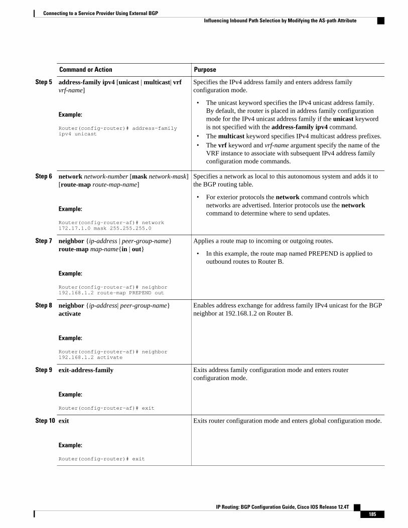
Command or Action Purpose
Step 5 address-family ipv4 [unicast | multicast| vrfvrf-name]
Example:
Router(config-router)# address-family ipv4 unicast
Specifies the IPv4 address family and enters address familyconfiguration mode.
• The unicast keyword specifies the IPv4 unicast address family.By default, the router is placed in address family configurationmode for the IPv4 unicast address family if the unicast keywordis not specified with the address-family ipv4 command.
• The multicast keyword specifies IPv4 multicast address prefixes.• The vrf keyword and vrf-name argument specify the name of the
VRF instance to associate with subsequent IPv4 address familyconfiguration mode commands.
Step 6 network network-number [mask network-mask][route-map route-map-name]
Example:
Router(config-router-af)# network 172.17.1.0 mask 255.255.255.0
Specifies a network as local to this autonomous system and adds it tothe BGP routing table.
• For exterior protocols the network command controls whichnetworks are advertised. Interior protocols use the networkcommand to determine where to send updates.
Step 7 neighbor {ip-address | peer-group-name}route-map map-name{in | out}
Example:
Router(config-router-af)# neighbor 192.168.1.2 route-map PREPEND out
Applies a route map to incoming or outgoing routes.
• In this example, the route map named PREPEND is applied tooutbound routes to Router B.
Step 8 neighbor {ip-address| peer-group-name}activate
Example:
Router(config-router-af)# neighbor 192.168.1.2 activate
Enables address exchange for address family IPv4 unicast for the BGPneighbor at 192.168.1.2 on Router B.
Step 9 exit-address-family
Example:
Router(config-router-af)# exit
Exits address family configuration mode and enters routerconfiguration mode.
Step 10 exit
Example:
Router(config-router)# exit
Exits router configuration mode and enters global configuration mode.
Connecting to a Service Provider Using External BGPInfluencing Inbound Path Selection by Modifying the AS-path Attribute
IP Routing: BGP Configuration Guide, Cisco IOS Release 12.4T 185
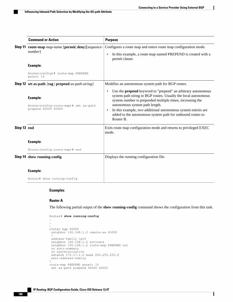
Command or Action Purpose
Step 11 route-map map-name [permit| deny][sequence-number]
Example:
Router(config)# route-map PREPEND permit 10
Configures a route map and enters route map configuration mode.
• In this example, a route map named PREPEND is created with apermit clause.
Step 12 set as-path {tag | prepend as-path-string}
Example:
Router(config-route-map)# set as-path prepend 40000 40000
Modifies an autonomous system path for BGP routes.
• Use the prepend keyword to "prepend" an arbitrary autonomoussystem path string to BGP routes. Usually the local autonomoussystem number is prepended multiple times, increasing theautonomous system path length.
• In this example, two additional autonomous system entries areadded to the autonomous system path for outbound routes toRouter B.
Step 13 end
Example:
Router(config-route-map)# end
Exits route map configuration mode and returns to privileged EXECmode.
Step 14 show running-config
Example:
Router# show running-config
Displays the running configuration file.
Examples
Router A
The following partial output of the show running-config command shows the configuration from this task.
Router# show running-config...router bgp 40000 neighbor 192.168.1.2 remote-as 45000 ! address-family ipv4 neighbor 192.168.1.2 activate neighbor 192.168.1.2 route-map PREPEND out no auto-summary no synchronization network 172.17.1.0 mask 255.255.255.0 exit-address-family!route-map PREPEND permit 10 set as-path prepend 40000 40000
Connecting to a Service Provider Using External BGP Influencing Inbound Path Selection by Modifying the AS-path Attribute
IP Routing: BGP Configuration Guide, Cisco IOS Release 12.4T186
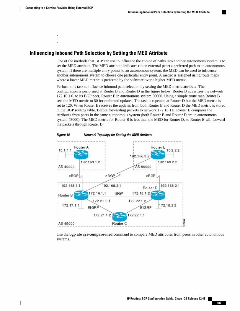
.
.
.
Influencing Inbound Path Selection by Setting the MED AttributeOne of the methods that BGP can use to influence the choice of paths into another autonomous system is toset the MED attribute. The MED attribute indicates (to an external peer) a preferred path to an autonomoussystem. If there are multiple entry points to an autonomous system, the MED can be used to influenceanother autonomous system to choose one particular entry point. A metric is assigned using route mapswhere a lower MED metric is preferred by the software over a higher MED metric.
Perform this task to influence inbound path selection by setting the MED metric attribute. Theconfiguration is performed at Router B and Router D in the figure below. Router B advertises the network172.16.1.0. to its BGP peer, Router E in autonomous system 50000. Using a simple route map Router Bsets the MED metric to 50 for outbound updates. The task is repeated at Router D but the MED metric isset to 120. When Router E receives the updates from both Router B and Router D the MED metric is storedin the BGP routing table. Before forwarding packets to network 172.16.1.0, Router E compares theattributes from peers in the same autonomous system (both Router B and Router D are in autonomoussystem 45000). The MED metric for Router B is less than the MED for Router D, so Router E will forwardthe packets through Router B.
Figure 18 Network Topology for Setting the MED Attribute
Use the bgp always-compare-med command to compare MED attributes from peers in other autonomoussystems.
Connecting to a Service Provider Using External BGPInfluencing Inbound Path Selection by Setting the MED Attribute
IP Routing: BGP Configuration Guide, Cisco IOS Release 12.4T 187

SUMMARY STEPS
1. enable
2. configure terminal
3. router bgp autonomous-system-number
4. neighbor {ip-address | peer-group-name} remote-as autonomous-system-number
5. address-family ipv4 [unicast | multicast| vrf vrf-name]
6. network network-number [mask network-mask][route-map route-map-name]
7. neighbor {ip-address | peer-group-name} route-map map-name{in | out}
8. exit
9. exit
10. route-map map-name [permit| deny][sequence-number]
11. set metric value
12. end
13. Repeat Step 1 through Step 12 at Router D.
14. show ip bgp [network] [network-mask]
DETAILED STEPS
Command or Action Purpose
Step 1 enable
Example:
Router> enable
Enables privileged EXEC mode.
• Enter your password if prompted.
Step 2 configure terminal
Example:
Router# configure terminal
Enters global configuration mode.
Step 3 router bgp autonomous-system-number
Example:
Router(config)# router bgp 45000
Enters router configuration mode for the specified routing process.
Step 4 neighbor {ip-address | peer-group-name}remote-as autonomous-system-number
Example:
Router(config-router)# neighbor 192.168.3.2 remote-as 50000
Adds the IP address or peer group name of the neighbor in thespecified autonomous system to the IPv4 multiprotocol BGPneighbor table of the local router.
Connecting to a Service Provider Using External BGP Influencing Inbound Path Selection by Setting the MED Attribute
IP Routing: BGP Configuration Guide, Cisco IOS Release 12.4T188
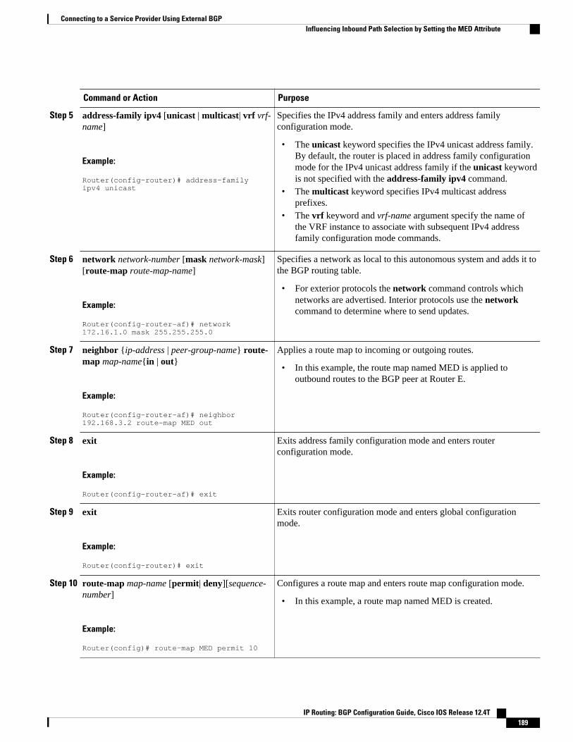
Command or Action Purpose
Step 5 address-family ipv4 [unicast | multicast| vrf vrf-name]
Example:
Router(config-router)# address-family ipv4 unicast
Specifies the IPv4 address family and enters address familyconfiguration mode.
• The unicast keyword specifies the IPv4 unicast address family.By default, the router is placed in address family configurationmode for the IPv4 unicast address family if the unicast keywordis not specified with the address-family ipv4 command.
• The multicast keyword specifies IPv4 multicast addressprefixes.
• The vrf keyword and vrf-name argument specify the name ofthe VRF instance to associate with subsequent IPv4 addressfamily configuration mode commands.
Step 6 network network-number [mask network-mask][route-map route-map-name]
Example:
Router(config-router-af)# network 172.16.1.0 mask 255.255.255.0
Specifies a network as local to this autonomous system and adds it tothe BGP routing table.
• For exterior protocols the network command controls whichnetworks are advertised. Interior protocols use the networkcommand to determine where to send updates.
Step 7 neighbor {ip-address | peer-group-name} route-map map-name{in | out}
Example:
Router(config-router-af)# neighbor 192.168.3.2 route-map MED out
Applies a route map to incoming or outgoing routes.
• In this example, the route map named MED is applied tooutbound routes to the BGP peer at Router E.
Step 8 exit
Example:
Router(config-router-af)# exit
Exits address family configuration mode and enters routerconfiguration mode.
Step 9 exit
Example:
Router(config-router)# exit
Exits router configuration mode and enters global configurationmode.
Step 10 route-map map-name [permit| deny][sequence-number]
Example:
Router(config)# route-map MED permit 10
Configures a route map and enters route map configuration mode.
• In this example, a route map named MED is created.
Connecting to a Service Provider Using External BGPInfluencing Inbound Path Selection by Setting the MED Attribute
IP Routing: BGP Configuration Guide, Cisco IOS Release 12.4T 189
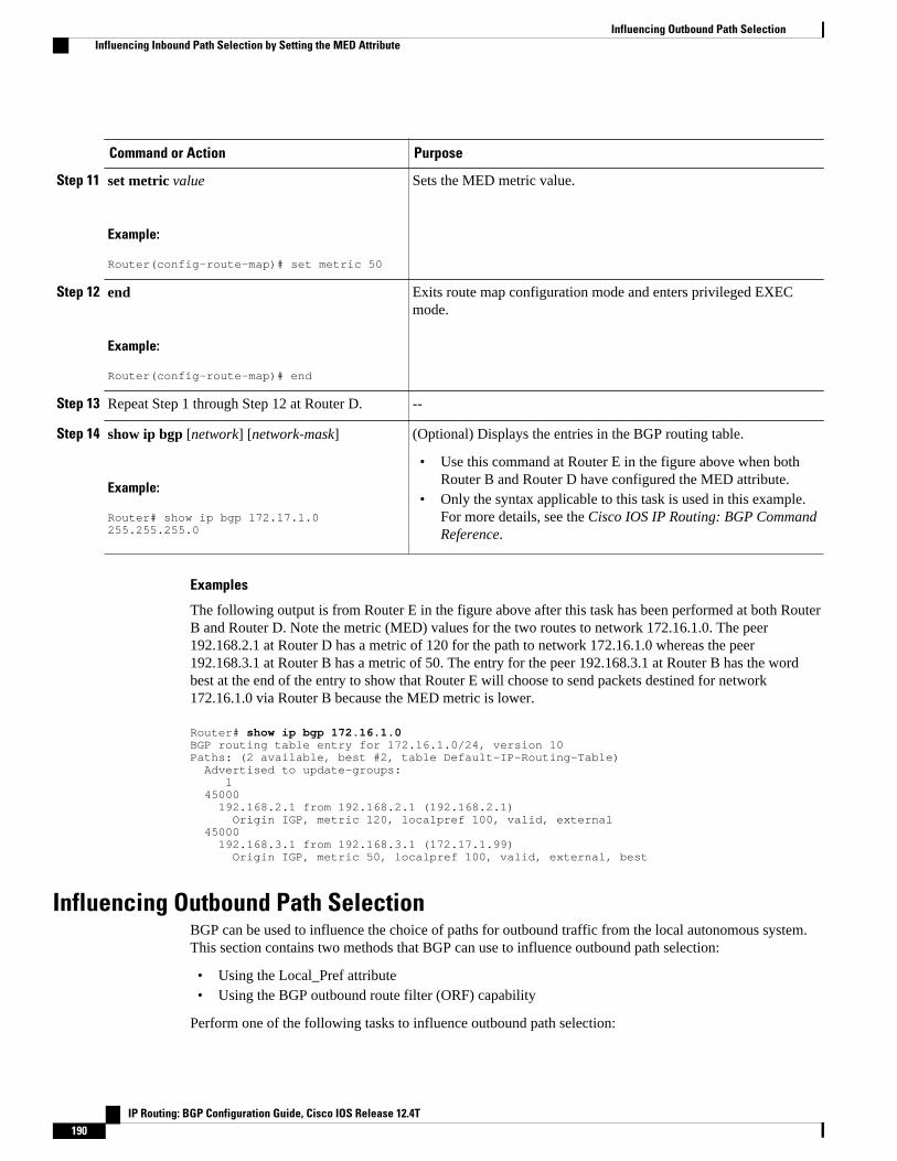
Command or Action Purpose
Step 11 set metric value
Example:
Router(config-route-map)# set metric 50
Sets the MED metric value.
Step 12 end
Example:
Router(config-route-map)# end
Exits route map configuration mode and enters privileged EXECmode.
Step 13 Repeat Step 1 through Step 12 at Router D. --
Step 14 show ip bgp [network] [network-mask]
Example:
Router# show ip bgp 172.17.1.0 255.255.255.0
(Optional) Displays the entries in the BGP routing table.
• Use this command at Router E in the figure above when bothRouter B and Router D have configured the MED attribute.
• Only the syntax applicable to this task is used in this example.For more details, see the Cisco IOS IP Routing: BGP CommandReference.
Examples
The following output is from Router E in the figure above after this task has been performed at both RouterB and Router D. Note the metric (MED) values for the two routes to network 172.16.1.0. The peer192.168.2.1 at Router D has a metric of 120 for the path to network 172.16.1.0 whereas the peer192.168.3.1 at Router B has a metric of 50. The entry for the peer 192.168.3.1 at Router B has the wordbest at the end of the entry to show that Router E will choose to send packets destined for network172.16.1.0 via Router B because the MED metric is lower.
Router# show ip bgp 172.16.1.0BGP routing table entry for 172.16.1.0/24, version 10Paths: (2 available, best #2, table Default-IP-Routing-Table) Advertised to update-groups: 1 45000 192.168.2.1 from 192.168.2.1 (192.168.2.1) Origin IGP, metric 120, localpref 100, valid, external 45000 192.168.3.1 from 192.168.3.1 (172.17.1.99) Origin IGP, metric 50, localpref 100, valid, external, best
Influencing Outbound Path SelectionBGP can be used to influence the choice of paths for outbound traffic from the local autonomous system.This section contains two methods that BGP can use to influence outbound path selection:
• Using the Local_Pref attribute• Using the BGP outbound route filter (ORF) capability
Perform one of the following tasks to influence outbound path selection:
Influencing Outbound Path Selection Influencing Inbound Path Selection by Setting the MED Attribute
IP Routing: BGP Configuration Guide, Cisco IOS Release 12.4T190

• Influencing Outbound Path Selection Using the Local_Pref Attribute, page 191
• Filtering Outbound BGP Route Prefixes, page 194
Influencing Outbound Path Selection Using the Local_Pref AttributeOne of the methods to influence outbound path selection is to use the BGP Local-Pref attribute. Performthis task using the local preference attribute to influence outbound path selection. If there are several pathsto the same destination the local preference attribute with the highest value indicates the preferred path.
Refer to the figure below for the network topology used in this task. Both Router B and Router C areconfigured. autonomous system 45000 receives updates for network 192.168.3.0 via autonomous system40000 and autonomous system 50000. Router B is configured to set the local preference value to 150 for allupdates to autonomous system 40000. Router C is configured to set the local preference value for allupdates to autonomous system 50000 to 200. After the configuration, local preference information isexchanged within autonomous system 45000. Router B and Router C now see that updates for network192.168.3.0 have a higher preference value from autonomous system 50000 so all traffic in autonomoussystem 45000 with a destination network of 192.168.3.0 is sent out via Router C.
Figure 19 Network Topology for Outbound Path Selection
Connecting to a Service Provider Using External BGPInfluencing Outbound Path Selection Using the Local_Pref Attribute
IP Routing: BGP Configuration Guide, Cisco IOS Release 12.4T 191
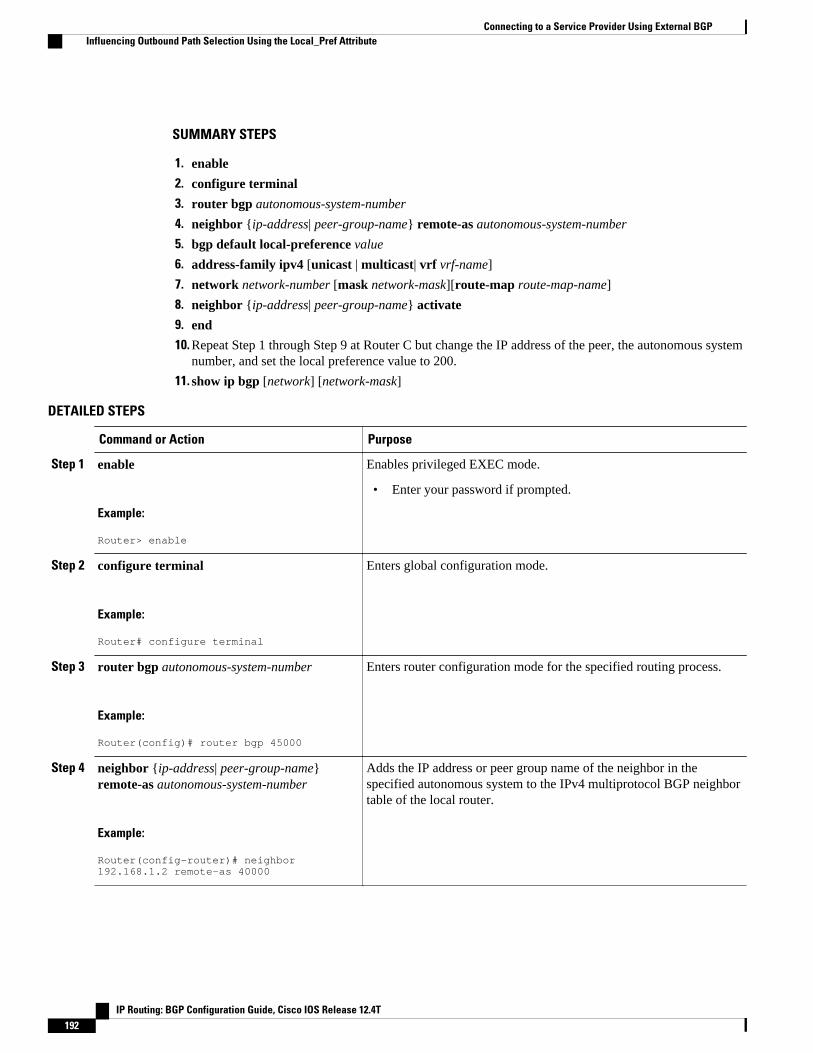
SUMMARY STEPS
1. enable
2. configure terminal
3. router bgp autonomous-system-number
4. neighbor {ip-address| peer-group-name} remote-as autonomous-system-number
5. bgp default local-preference value
6. address-family ipv4 [unicast | multicast| vrf vrf-name]
7. network network-number [mask network-mask][route-map route-map-name]
8. neighbor {ip-address| peer-group-name} activate
9. end
10. Repeat Step 1 through Step 9 at Router C but change the IP address of the peer, the autonomous systemnumber, and set the local preference value to 200.
11. show ip bgp [network] [network-mask]
DETAILED STEPS
Command or Action Purpose
Step 1 enable
Example:
Router> enable
Enables privileged EXEC mode.
• Enter your password if prompted.
Step 2 configure terminal
Example:
Router# configure terminal
Enters global configuration mode.
Step 3 router bgp autonomous-system-number
Example:
Router(config)# router bgp 45000
Enters router configuration mode for the specified routing process.
Step 4 neighbor {ip-address| peer-group-name}remote-as autonomous-system-number
Example:
Router(config-router)# neighbor 192.168.1.2 remote-as 40000
Adds the IP address or peer group name of the neighbor in thespecified autonomous system to the IPv4 multiprotocol BGP neighbortable of the local router.
Connecting to a Service Provider Using External BGP Influencing Outbound Path Selection Using the Local_Pref Attribute
IP Routing: BGP Configuration Guide, Cisco IOS Release 12.4T192
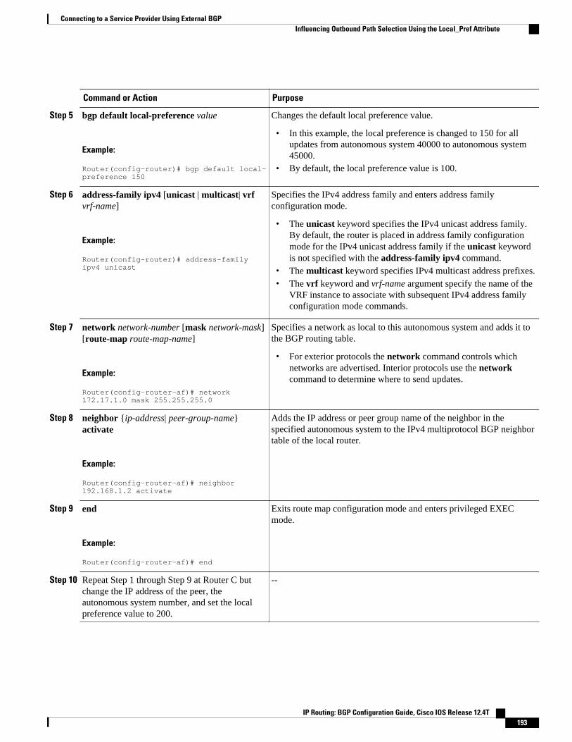
Command or Action Purpose
Step 5 bgp default local-preference value
Example:
Router(config-router)# bgp default local-preference 150
Changes the default local preference value.
• In this example, the local preference is changed to 150 for allupdates from autonomous system 40000 to autonomous system45000.
• By default, the local preference value is 100.
Step 6 address-family ipv4 [unicast | multicast| vrfvrf-name]
Example:
Router(config-router)# address-family ipv4 unicast
Specifies the IPv4 address family and enters address familyconfiguration mode.
• The unicast keyword specifies the IPv4 unicast address family.By default, the router is placed in address family configurationmode for the IPv4 unicast address family if the unicast keywordis not specified with the address-family ipv4 command.
• The multicast keyword specifies IPv4 multicast address prefixes.• The vrf keyword and vrf-name argument specify the name of the
VRF instance to associate with subsequent IPv4 address familyconfiguration mode commands.
Step 7 network network-number [mask network-mask][route-map route-map-name]
Example:
Router(config-router-af)# network 172.17.1.0 mask 255.255.255.0
Specifies a network as local to this autonomous system and adds it tothe BGP routing table.
• For exterior protocols the network command controls whichnetworks are advertised. Interior protocols use the networkcommand to determine where to send updates.
Step 8 neighbor {ip-address| peer-group-name}activate
Example:
Router(config-router-af)# neighbor 192.168.1.2 activate
Adds the IP address or peer group name of the neighbor in thespecified autonomous system to the IPv4 multiprotocol BGP neighbortable of the local router.
Step 9 end
Example:
Router(config-router-af)# end
Exits route map configuration mode and enters privileged EXECmode.
Step 10 Repeat Step 1 through Step 9 at Router C butchange the IP address of the peer, theautonomous system number, and set the localpreference value to 200.
--
Connecting to a Service Provider Using External BGPInfluencing Outbound Path Selection Using the Local_Pref Attribute
IP Routing: BGP Configuration Guide, Cisco IOS Release 12.4T 193

Command or Action Purpose
Step 11 show ip bgp [network] [network-mask]
Example:
Router# show ip bgp 192.168.3.0 255.255.255.0
Displays the entries in the BGP routing table.
• Enter this command at both Router B and Router C and note theLocal_Pref value. The route with the highest preference valuewill be the preferred route to network 192.168.3.0.
Note Only the syntax applicable to this task is used in this example.For more details, see the Cisco IOS IP Routing: BGP CommandReference.
Filtering Outbound BGP Route PrefixesPerform this task to use BGP prefix-based outbound route filtering to influence outbound path selection.
BGP peering sessions must be established, and BGP ORF capabilities must be enabled on eachparticipating router before prefix-based ORF announcements can be received.
Note• BGP prefix-based outbound route filtering does not support multicast.• IP addresses that are used for outbound route filtering must be defined in an IP prefix list. BGP
distribute lists and IP access lists are not supported.• Outbound route filtering is configured on only a per-address family basis and cannot be configured
under the general session or BGP routing process.• Outbound route filtering is configured for external peering sessions only.
>
SUMMARY STEPS
1. enable
2. configure terminal
3. ip prefix-list list-name [seq seq-value] {deny network / length | permit network / length}[ge ge-value][le le-value]
4. router bgp autonomous-system-number
5. neighbor {ip-address| peer-group-name} remote-as autonomous-system-number
6. neighbor ip-address ebgp-multihop [hop-count]
7. address-family ipv4 [unicast | multicast| vrf vrf-name]
8. neighbor ip-address capability orf prefix-list [send | receive | both]
9. neighbor {ip-address| peer-group-name} prefix-list prefix-list-name{in | out}
10. end
11. clear ip bgp {ip-address | *} in prefix-filter
Connecting to a Service Provider Using External BGP Filtering Outbound BGP Route Prefixes
IP Routing: BGP Configuration Guide, Cisco IOS Release 12.4T194

DETAILED STEPS
Command or Action Purpose
Step 1 enable
Example:
Router> enable
Enables privileged EXEC mode.
• Enter your password if prompted.
Step 2 configure terminal
Example:
Router# configure terminal
Enters global configuration mode.
Step 3 ip prefix-list list-name [seq seq-value]{deny network / length | permit network /length}[ge ge-value] [le le-value]
Example:
Router(config)# ip prefix-list FILTER seq 10 permit 192.168.1.0/24
Creates a prefix list for prefix-based outbound route filtering.
• Outbound route filtering supports prefix length matching, wildcard-based prefix matching, and exact address prefix matching on a peraddress-family basis.
• The prefix list is created to define the outbound route filter. The filtermust be created when the outbound route filtering capability isconfigured to be advertised in send mode or both mode. It is notrequired when a peer is configured to advertise receive mode only.
• The example creates a prefix list named FILTER that defines the192.168.1.0/24 subnet for outbound route filtering.
Step 4 router bgp autonomous-system-number
Example:
Router(config)# router bgp 100
Enters router configuration mode, and creates a BGP routing process.
Step 5 neighbor {ip-address| peer-group-name}remote-as autonomous-system-number
Example:
Router(config-router)# neighbor 10.1.1.1 remote-as 200
Establishes peering with the specified neighbor or peer group. BGPpeering must be established before ORF capabilities can be exchanged.
• The example establishes peering with the 10.1.1.1 neighbor.
Step 6 neighbor ip-address ebgp-multihop [hop-count]
Example:
Router(config-router)# neighbor 10.1.1.1 ebgp-multihop
Accepts or initiates BGP connections to external peers residing onnetworks that are not directly connected.
Connecting to a Service Provider Using External BGPFiltering Outbound BGP Route Prefixes
IP Routing: BGP Configuration Guide, Cisco IOS Release 12.4T 195

Command or Action Purpose
Step 7 address-family ipv4 [unicast | multicast|vrf vrf-name]
Example:
Router(config-router)# address-family ipv4 unicast
Specifies the IPv4 address family and enters address family configurationmode.
• The unicast keyword specifies the IPv4 unicast address family. Bydefault, the router is placed in address family configuration mode forthe IPv4 unicast address family if the unicast keyword is notspecified with the address-family ipv4 command.
• The multicast keyword specifies IPv4 multicast address prefixes.• The vrf keyword and vrf-name argument specify the name of the
VRF instance to associate with subsequent IPv4 address familyconfiguration mode commands.
Note Outbound route filtering is configured on a per-address familybasis.
Step 8 neighbor ip-address capability orf prefix-list [send | receive | both]
Example:
Router(config-router-af)# neighbor 10.1.1.1 capability orf prefix-list both
Enables the ORF capability on the local router, and enables ORFcapability advertisement to the BGP peer specified with the ip-addressargument.
• The send keyword configures a router to advertise ORF sendcapabilities.
• The receive keyword configures a router to advertise ORF receivecapabilities.
• The both keyword configures a router to advertise send and receivecapabilities.
• The remote peer must be configured to either send or receive ORFcapabilities before outbound route filtering is enabled.
• The example configures the router to advertise send and receivecapabilities to the 10.1.1.1 neighbor.
Step 9 neighbor {ip-address| peer-group-name}prefix-list prefix-list-name{in | out}
Example:
Router(config-router-af)# neighbor 10.1.1.1 prefix-list FILTER in
Applies an inbound prefix-list filter to prevent distribution of BGPneighbor information.
• In this example, the prefix list named FILTER is applied to incomingadvertisements from the 10.1.1.1 neighbor, which preventsdistribution of the 192.168.1.0/24 subnet.
Step 10 end
Example:
Router(config-router-af)# end
Exits address family configuration mode, and enters privileged EXECmode.
Connecting to a Service Provider Using External BGP Filtering Outbound BGP Route Prefixes
IP Routing: BGP Configuration Guide, Cisco IOS Release 12.4T196
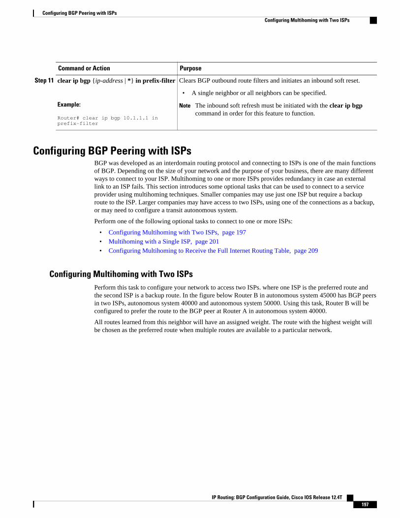
Command or Action Purpose
Step 11 clear ip bgp {ip-address | *} in prefix-filter
Example:
Router# clear ip bgp 10.1.1.1 in prefix-filter
Clears BGP outbound route filters and initiates an inbound soft reset.
• A single neighbor or all neighbors can be specified.
Note The inbound soft refresh must be initiated with the clear ip bgpcommand in order for this feature to function.
Configuring BGP Peering with ISPsBGP was developed as an interdomain routing protocol and connecting to ISPs is one of the main functionsof BGP. Depending on the size of your network and the purpose of your business, there are many differentways to connect to your ISP. Multihoming to one or more ISPs provides redundancy in case an externallink to an ISP fails. This section introduces some optional tasks that can be used to connect to a serviceprovider using multihoming techniques. Smaller companies may use just one ISP but require a backuproute to the ISP. Larger companies may have access to two ISPs, using one of the connections as a backup,or may need to configure a transit autonomous system.
Perform one of the following optional tasks to connect to one or more ISPs:
• Configuring Multihoming with Two ISPs, page 197
• Multihoming with a Single ISP, page 201
• Configuring Multihoming to Receive the Full Internet Routing Table, page 209
Configuring Multihoming with Two ISPsPerform this task to configure your network to access two ISPs. where one ISP is the preferred route andthe second ISP is a backup route. In the figure below Router B in autonomous system 45000 has BGP peersin two ISPs, autonomous system 40000 and autonomous system 50000. Using this task, Router B will beconfigured to prefer the route to the BGP peer at Router A in autonomous system 40000.
All routes learned from this neighbor will have an assigned weight. The route with the highest weight willbe chosen as the preferred route when multiple routes are available to a particular network.
Configuring BGP Peering with ISPsConfiguring Multihoming with Two ISPs
IP Routing: BGP Configuration Guide, Cisco IOS Release 12.4T 197
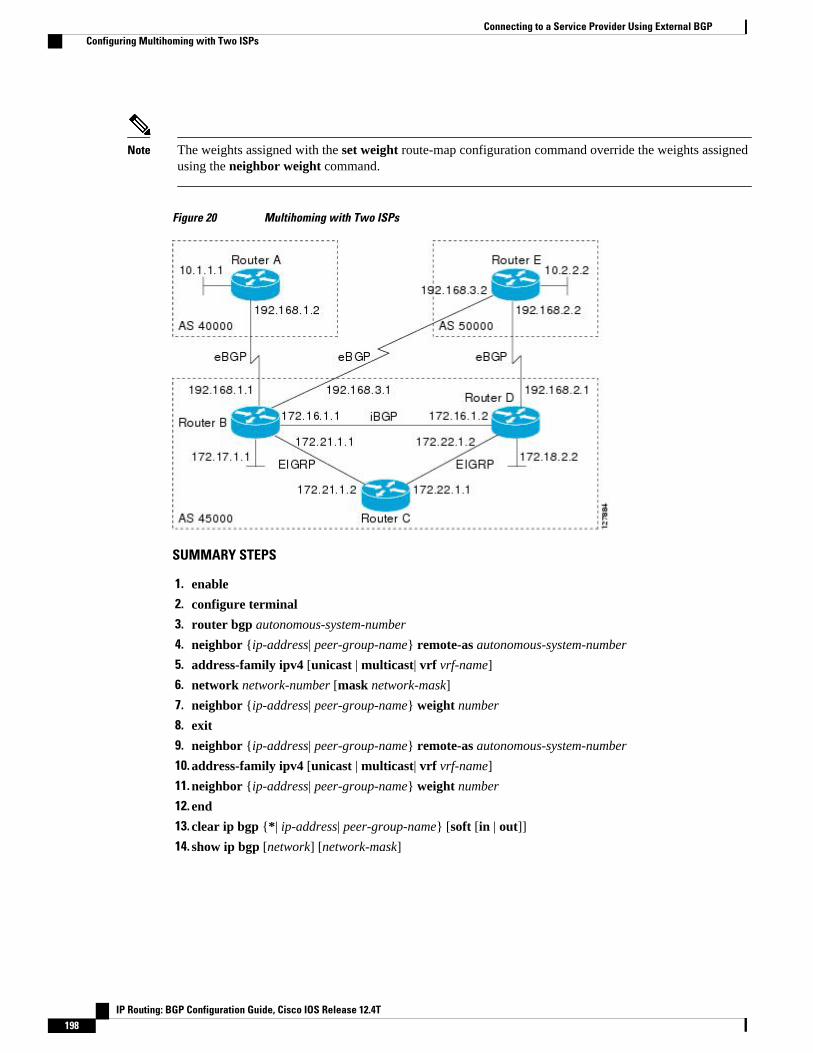
Note The weights assigned with the set weight route-map configuration command override the weights assignedusing the neighbor weight command.
Figure 20 Multihoming with Two ISPs
SUMMARY STEPS
1. enable
2. configure terminal
3. router bgp autonomous-system-number
4. neighbor {ip-address| peer-group-name} remote-as autonomous-system-number
5. address-family ipv4 [unicast | multicast| vrf vrf-name]
6. network network-number [mask network-mask]
7. neighbor {ip-address| peer-group-name} weight number
8. exit
9. neighbor {ip-address| peer-group-name} remote-as autonomous-system-number
10. address-family ipv4 [unicast | multicast| vrf vrf-name]
11. neighbor {ip-address| peer-group-name} weight number
12. end
13. clear ip bgp {*| ip-address| peer-group-name} [soft [in | out]]
14. show ip bgp [network] [network-mask]
Connecting to a Service Provider Using External BGP Configuring Multihoming with Two ISPs
IP Routing: BGP Configuration Guide, Cisco IOS Release 12.4T198

DETAILED STEPS
Command or Action Purpose
Step 1 enable
Example:
Router> enable
Enables privileged EXEC mode.
• Enter your password if prompted.
Step 2 configure terminal
Example:
Router# configure terminal
Enters global configuration mode.
Step 3 router bgp autonomous-system-number
Example:
Router(config)# router bgp 45000
Enters router configuration mode, and creates a BGP routing process.
Step 4 neighbor {ip-address| peer-group-name}remote-as autonomous-system-number
Example:
Router(config-router)# neighbor 192.168.1.2 remote-as 40000
Adds the IP address or peer group name of the neighbor in the specifiedautonomous system to the IPv4 multiprotocol BGP neighbor table of thelocal router.
Step 5 address-family ipv4 [unicast | multicast| vrfvrf-name]
Example:
Router(config-router)# address-family ipv4 unicast
Specifies the IPv4 address family and enters address familyconfiguration mode.
• The unicast keyword specifies the IPv4 unicast address family. Bydefault, the router is placed in configuration mode for the IPv4unicast address family if the unicast keyword is not specified withthe address-family ipv4 command.
• The multicast keyword specifies IPv4 multicast address prefixes.• The vrf keyword and vrf-name argument specify the name of the
VRF instance to associate with subsequent IPv4 address familyconfiguration mode commands.
Step 6 network network-number [mask network-mask]
Example:
Router(config-router-af)# network 172.17.1.0 mask 255.255.255.0
Specifies a network as local to this autonomous system and adds it to theBGP routing table.
• For exterior protocols the network command controls whichnetworks are advertised. Interior protocols use the networkcommand to determine where to send updates.
Connecting to a Service Provider Using External BGPConfiguring Multihoming with Two ISPs
IP Routing: BGP Configuration Guide, Cisco IOS Release 12.4T 199

Command or Action Purpose
Step 7 neighbor {ip-address| peer-group-name}weight number
Example:
Router(config-router-af)# neighbor 192.168.1.2 weight 150
Assigns a weight to a BGP peer connection.
• In this example, the weight attribute for routes received from theBGP peer 192.168.1.2 is set to 150.
Step 8 exit
Example:
Router(config-router-af)# exit
Exits address family configuration mode and enters router configurationmode.
Step 9 neighbor {ip-address| peer-group-name}remote-as autonomous-system-number
Example:
Router(config-router)# neighbor 192.168.3.2 remote-as 50000
Adds the IP address or peer group name of the neighbor in the specifiedautonomous system to the IPv4 multiprotocol BGP neighbor table of thelocal router.
Step 10 address-family ipv4 [unicast | multicast| vrfvrf-name]
Example:
Router(config-router)# address-family ipv4 unicast
Specifies the IPv4 address family and enters address familyconfiguration mode.
• The unicast keyword specifies the IPv4 unicast address family. Bydefault, the router is placed in configuration mode for the IPv4unicast address family if the unicast keyword is not specified withthe address-family ipv4 command.
• The multicast keyword specifies IPv4 multicast address prefixes.
The vrf keyword and vrf-name argument specify the name of the VRFinstance to associate with subsequent IPv4 address family configurationmode commands.
Step 11 neighbor {ip-address| peer-group-name}weight number
Example:
Router(config-router-af)# neighbor 192.168.3.2 weight 100
Assigns a weight to a BGP peer connection.
• In this example, the weight attribute for routes received from theBGP peer 192.168.3.2 is set to 100.
Step 12 end
Example:
Router(config-router-af)# end
Exits address family configuration mode and enters privileged EXECmode.
Connecting to a Service Provider Using External BGP Configuring Multihoming with Two ISPs
IP Routing: BGP Configuration Guide, Cisco IOS Release 12.4T200
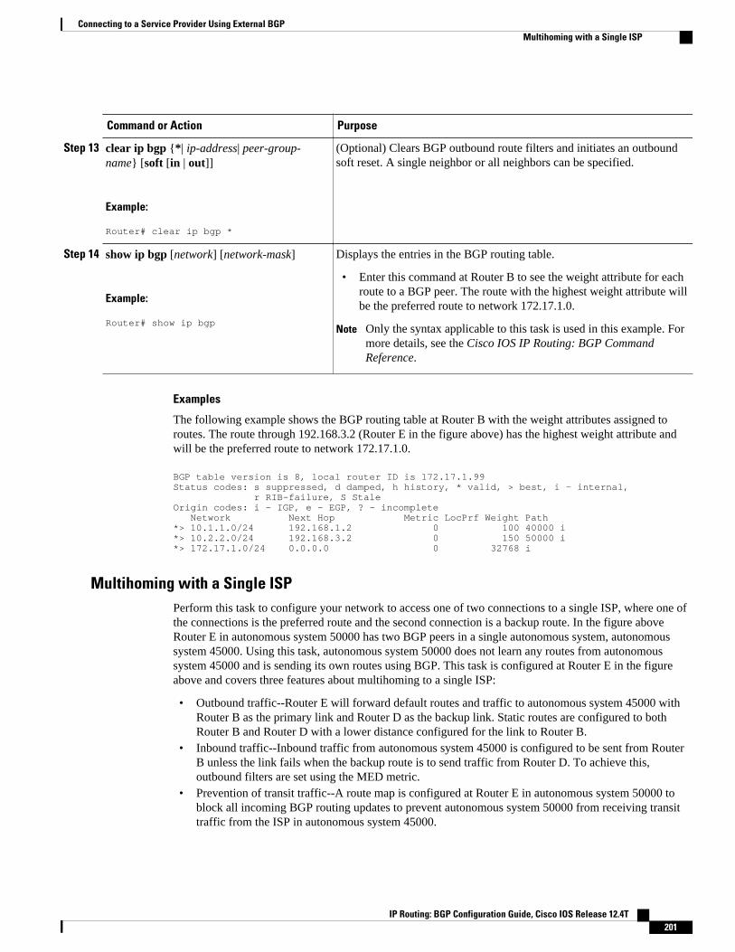
Command or Action Purpose
Step 13 clear ip bgp {*| ip-address| peer-group-name} [soft [in | out]]
Example:
Router# clear ip bgp *
(Optional) Clears BGP outbound route filters and initiates an outboundsoft reset. A single neighbor or all neighbors can be specified.
Step 14 show ip bgp [network] [network-mask]
Example:
Router# show ip bgp
Displays the entries in the BGP routing table.
• Enter this command at Router B to see the weight attribute for eachroute to a BGP peer. The route with the highest weight attribute willbe the preferred route to network 172.17.1.0.
Note Only the syntax applicable to this task is used in this example. Formore details, see the Cisco IOS IP Routing: BGP CommandReference.
Examples
The following example shows the BGP routing table at Router B with the weight attributes assigned toroutes. The route through 192.168.3.2 (Router E in the figure above) has the highest weight attribute andwill be the preferred route to network 172.17.1.0.
BGP table version is 8, local router ID is 172.17.1.99Status codes: s suppressed, d damped, h history, * valid, > best, i - internal, r RIB-failure, S StaleOrigin codes: i - IGP, e - EGP, ? - incomplete Network Next Hop Metric LocPrf Weight Path*> 10.1.1.0/24 192.168.1.2 0 100 40000 i*> 10.2.2.0/24 192.168.3.2 0 150 50000 i*> 172.17.1.0/24 0.0.0.0 0 32768 i
Multihoming with a Single ISPPerform this task to configure your network to access one of two connections to a single ISP, where one ofthe connections is the preferred route and the second connection is a backup route. In the figure aboveRouter E in autonomous system 50000 has two BGP peers in a single autonomous system, autonomoussystem 45000. Using this task, autonomous system 50000 does not learn any routes from autonomoussystem 45000 and is sending its own routes using BGP. This task is configured at Router E in the figureabove and covers three features about multihoming to a single ISP:
• Outbound traffic--Router E will forward default routes and traffic to autonomous system 45000 withRouter B as the primary link and Router D as the backup link. Static routes are configured to bothRouter B and Router D with a lower distance configured for the link to Router B.
• Inbound traffic--Inbound traffic from autonomous system 45000 is configured to be sent from RouterB unless the link fails when the backup route is to send traffic from Router D. To achieve this,outbound filters are set using the MED metric.
• Prevention of transit traffic--A route map is configured at Router E in autonomous system 50000 toblock all incoming BGP routing updates to prevent autonomous system 50000 from receiving transittraffic from the ISP in autonomous system 45000.
Connecting to a Service Provider Using External BGPMultihoming with a Single ISP
IP Routing: BGP Configuration Guide, Cisco IOS Release 12.4T 201
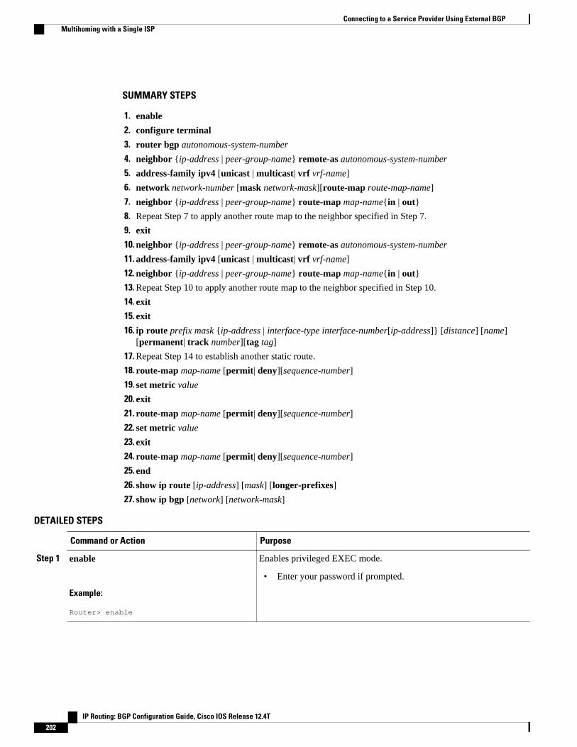
SUMMARY STEPS
1. enable
2. configure terminal
3. router bgp autonomous-system-number
4. neighbor {ip-address | peer-group-name} remote-as autonomous-system-number
5. address-family ipv4 [unicast | multicast| vrf vrf-name]
6. network network-number [mask network-mask][route-map route-map-name]
7. neighbor {ip-address | peer-group-name} route-map map-name{in | out}
8. Repeat Step 7 to apply another route map to the neighbor specified in Step 7.
9. exit
10. neighbor {ip-address | peer-group-name} remote-as autonomous-system-number
11. address-family ipv4 [unicast | multicast| vrf vrf-name]
12. neighbor {ip-address | peer-group-name} route-map map-name{in | out}
13. Repeat Step 10 to apply another route map to the neighbor specified in Step 10.
14. exit
15. exit
16. ip route prefix mask {ip-address | interface-type interface-number[ip-address]} [distance] [name][permanent| track number][tag tag]
17. Repeat Step 14 to establish another static route.
18. route-map map-name [permit| deny][sequence-number]
19. set metric value
20. exit
21. route-map map-name [permit| deny][sequence-number]
22. set metric value
23. exit
24. route-map map-name [permit| deny][sequence-number]
25. end
26. show ip route [ip-address] [mask] [longer-prefixes]
27. show ip bgp [network] [network-mask]
DETAILED STEPS
Command or Action Purpose
Step 1 enable
Example:
Router> enable
Enables privileged EXEC mode.
• Enter your password if prompted.
Connecting to a Service Provider Using External BGP Multihoming with a Single ISP
IP Routing: BGP Configuration Guide, Cisco IOS Release 12.4T202
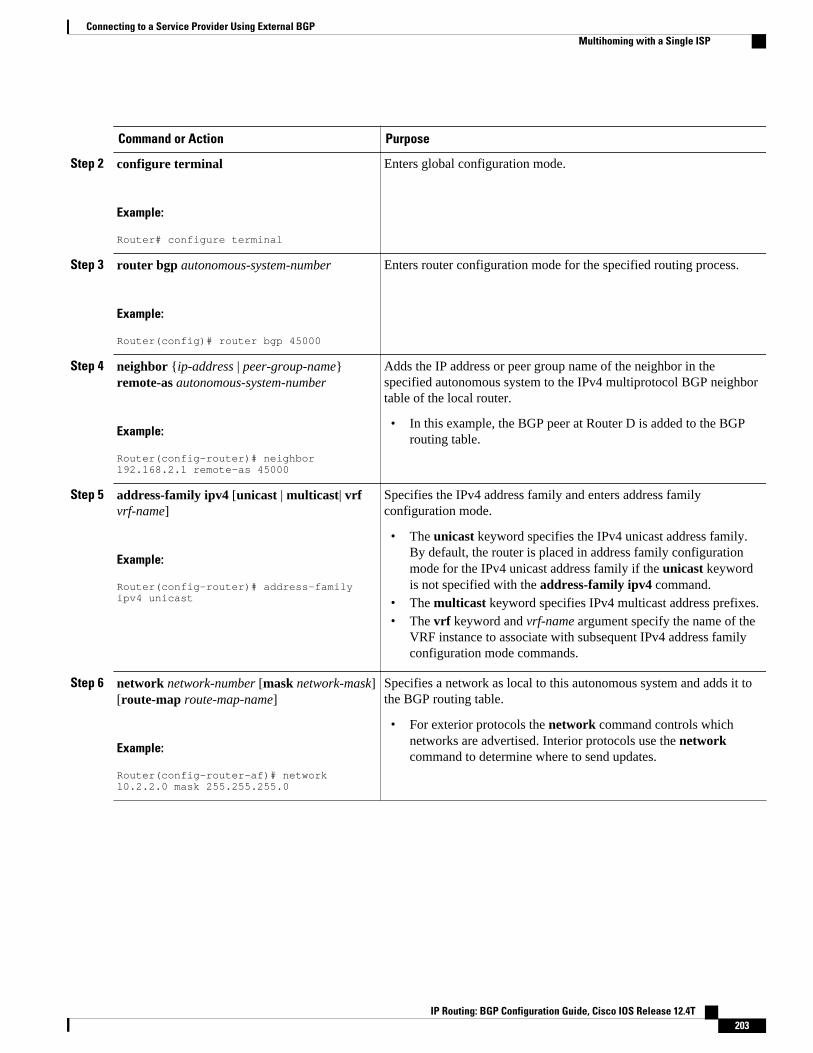
Command or Action Purpose
Step 2 configure terminal
Example:
Router# configure terminal
Enters global configuration mode.
Step 3 router bgp autonomous-system-number
Example:
Router(config)# router bgp 45000
Enters router configuration mode for the specified routing process.
Step 4 neighbor {ip-address | peer-group-name}remote-as autonomous-system-number
Example:
Router(config-router)# neighbor 192.168.2.1 remote-as 45000
Adds the IP address or peer group name of the neighbor in thespecified autonomous system to the IPv4 multiprotocol BGP neighbortable of the local router.
• In this example, the BGP peer at Router D is added to the BGProuting table.
Step 5 address-family ipv4 [unicast | multicast| vrfvrf-name]
Example:
Router(config-router)# address-family ipv4 unicast
Specifies the IPv4 address family and enters address familyconfiguration mode.
• The unicast keyword specifies the IPv4 unicast address family.By default, the router is placed in address family configurationmode for the IPv4 unicast address family if the unicast keywordis not specified with the address-family ipv4 command.
• The multicast keyword specifies IPv4 multicast address prefixes.• The vrf keyword and vrf-name argument specify the name of the
VRF instance to associate with subsequent IPv4 address familyconfiguration mode commands.
Step 6 network network-number [mask network-mask][route-map route-map-name]
Example:
Router(config-router-af)# network 10.2.2.0 mask 255.255.255.0
Specifies a network as local to this autonomous system and adds it tothe BGP routing table.
• For exterior protocols the network command controls whichnetworks are advertised. Interior protocols use the networkcommand to determine where to send updates.
Connecting to a Service Provider Using External BGPMultihoming with a Single ISP
IP Routing: BGP Configuration Guide, Cisco IOS Release 12.4T 203

Command or Action Purpose
Step 7 neighbor {ip-address | peer-group-name}route-map map-name{in | out}
Example:
Router(config-router-af)# neighbor 192.168.2.1 route-map BLOCK in
Example:
Router(config-router-af)# neighbor 192.168.2.1 route-map SETMETRIC1 out
Applies a route map to incoming or outgoing routes.
• In the first example, the route map named BLOCK is applied toinbound routes at Router E.
• In the second example, the route map named SETMETRIC1 isapplied to outbound routes to Router D.
Note Two examples are shown here because the task examplerequires both these statements to be configured.
Step 8 Repeat Step 7 to apply another route map to theneighbor specified in Step 7.
--
Step 9 exit
Example:
Router(config-router-af)# exit
Exits address family configuration mode and enters routerconfiguration mode.
Step 10 neighbor {ip-address | peer-group-name}remote-as autonomous-system-number
Example:
Router(config-router)# neighbor 192.168.3.1 remote-as 45000
Adds the IP address or peer group name of the neighbor in thespecified autonomous system to the IPv4 multiprotocol BGP neighbortable of the local router.
• In this example, the BGP peer at Router D is added to the BGProuting table.
Step 11 address-family ipv4 [unicast | multicast| vrfvrf-name]
Example:
Router(config-router)# address-family ipv4 unicast
Specifies the IPv4 address family and enters address familyconfiguration mode.
• The unicast keyword specifies the IPv4 unicast address family.By default, the router is placed in address family configurationmode for the IPv4 unicast address family if the unicast keywordis not specified with the address-family ipv4 command.
• The multicast keyword specifies IPv4 multicast address prefixes.
The vrf keyword and vrf-name argument specify the name of the VRFinstance to associate with subsequent IPv4 address familyconfiguration mode commands.
Connecting to a Service Provider Using External BGP Multihoming with a Single ISP
IP Routing: BGP Configuration Guide, Cisco IOS Release 12.4T204

Command or Action Purpose
Step 12 neighbor {ip-address | peer-group-name}route-map map-name{in | out}
Example:
Router(config-router-af)# neighbor 192.168.3.1 route-map BLOCK in
Example:
Router(config-router-af)# neighbor 192.168.3.1 route-map SETMETRIC2 out
Applies a route map to incoming or outgoing routes.
• In the first example, the route map named BLOCK is applied toinbound routes at Router E.
• In the second example, the route map named SETMETRIC2 isapplied to outbound routes to Router D.
Note Two examples are shown here because the task examplerequires both these statements to be configured.
Step 13 Repeat Step 10 to apply another route map tothe neighbor specified in Step 10.
--
Step 14 exit
Example:
Router(config-router-af)# exit
Exits address family configuration mode and enters routerconfiguration mode.
Step 15 exit
Example:
Router(config-router)# exit
Exits router configuration mode and enters global configuration mode.
Connecting to a Service Provider Using External BGPMultihoming with a Single ISP
IP Routing: BGP Configuration Guide, Cisco IOS Release 12.4T 205
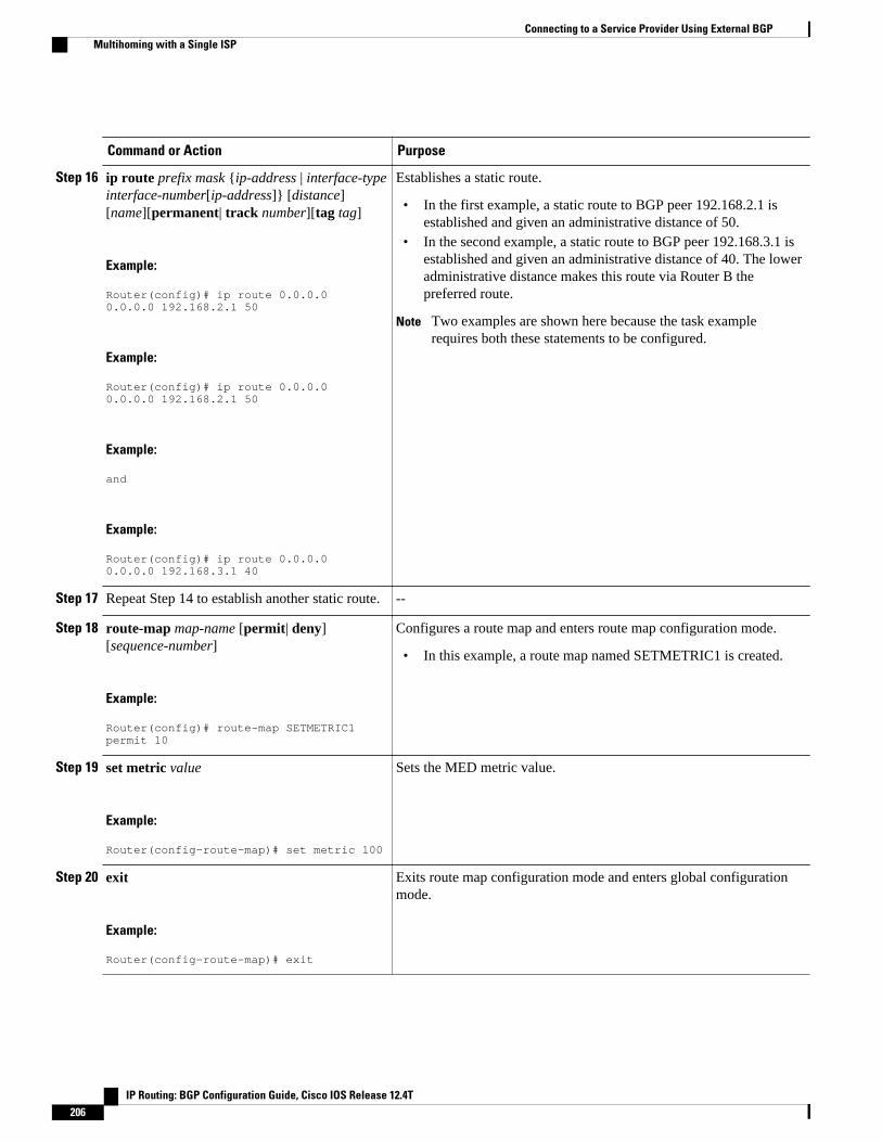
Command or Action Purpose
Step 16 ip route prefix mask {ip-address | interface-typeinterface-number[ip-address]} [distance][name][permanent| track number][tag tag]
Example:
Router(config)# ip route 0.0.0.0 0.0.0.0 192.168.2.1 50
Example:
Router(config)# ip route 0.0.0.0 0.0.0.0 192.168.2.1 50
Example:
and
Example:
Router(config)# ip route 0.0.0.0 0.0.0.0 192.168.3.1 40
Establishes a static route.
• In the first example, a static route to BGP peer 192.168.2.1 isestablished and given an administrative distance of 50.
• In the second example, a static route to BGP peer 192.168.3.1 isestablished and given an administrative distance of 40. The loweradministrative distance makes this route via Router B thepreferred route.
Note Two examples are shown here because the task examplerequires both these statements to be configured.
Step 17 Repeat Step 14 to establish another static route. --
Step 18 route-map map-name [permit| deny][sequence-number]
Example:
Router(config)# route-map SETMETRIC1 permit 10
Configures a route map and enters route map configuration mode.
• In this example, a route map named SETMETRIC1 is created.
Step 19 set metric value
Example:
Router(config-route-map)# set metric 100
Sets the MED metric value.
Step 20 exit
Example:
Router(config-route-map)# exit
Exits route map configuration mode and enters global configurationmode.
Connecting to a Service Provider Using External BGP Multihoming with a Single ISP
IP Routing: BGP Configuration Guide, Cisco IOS Release 12.4T206
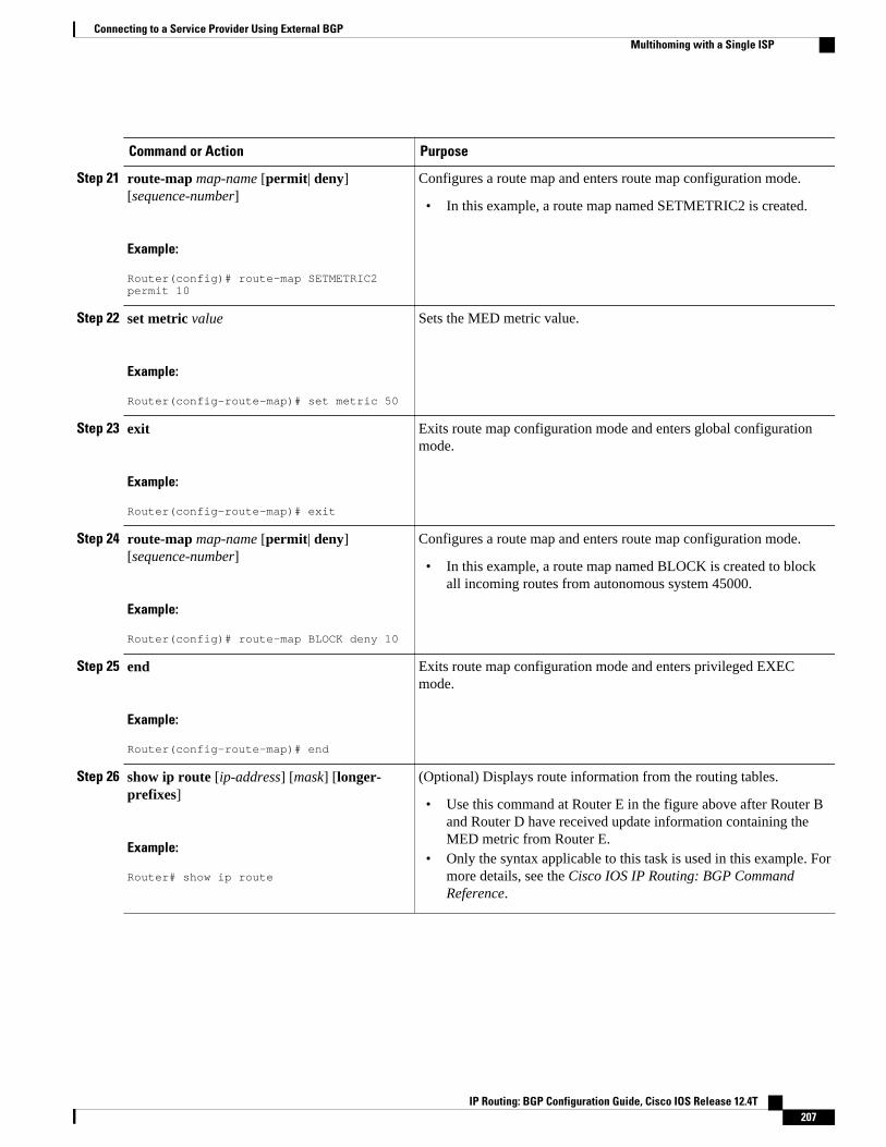
Command or Action Purpose
Step 21 route-map map-name [permit| deny][sequence-number]
Example:
Router(config)# route-map SETMETRIC2 permit 10
Configures a route map and enters route map configuration mode.
• In this example, a route map named SETMETRIC2 is created.
Step 22 set metric value
Example:
Router(config-route-map)# set metric 50
Sets the MED metric value.
Step 23 exit
Example:
Router(config-route-map)# exit
Exits route map configuration mode and enters global configurationmode.
Step 24 route-map map-name [permit| deny][sequence-number]
Example:
Router(config)# route-map BLOCK deny 10
Configures a route map and enters route map configuration mode.
• In this example, a route map named BLOCK is created to blockall incoming routes from autonomous system 45000.
Step 25 end
Example:
Router(config-route-map)# end
Exits route map configuration mode and enters privileged EXECmode.
Step 26 show ip route [ip-address] [mask] [longer-prefixes]
Example:
Router# show ip route
(Optional) Displays route information from the routing tables.
• Use this command at Router E in the figure above after Router Band Router D have received update information containing theMED metric from Router E.
• Only the syntax applicable to this task is used in this example. Formore details, see the Cisco IOS IP Routing: BGP CommandReference.
Connecting to a Service Provider Using External BGPMultihoming with a Single ISP
IP Routing: BGP Configuration Guide, Cisco IOS Release 12.4T 207

Command or Action Purpose
Step 27 show ip bgp [network] [network-mask]
Example:
Router# show ip bgp 172.17.1.0 255.255.255.0
(Optional) Displays the entries in the BGP routing table.
• Use this command at Router E in the figure above after Router Band Router D have received update information containing theMED metric from Router E.
• Only the syntax applicable to this task is used in this example. Formore details, see the Cisco IOS IP Routing: BGP CommandReference.
Examples
The following example shows output from the show ip route command entered at Router E after this taskhas been configured and Router B and Router D have received update information containing the MEDmetric. Note that the gateway of last resort is set as 192.168.3.1, which is the route to Router B.
Router# show ip routeCodes: C - connected, S - static, R - RIP, M - mobile, B - BGP D - EIGRP, EX - EIGRP external, O - OSPF, IA - OSPF inter area N1 - OSPF NSSA external type 1, N2 - OSPF NSSA external type 2 E1 - OSPF external type 1, E2 - OSPF external type 2 i - IS-IS, su - IS-IS summary, L1 - IS-IS level-1, L2 - IS-IS level-2 ia - IS-IS inter area, * - candidate default, U - per-user static route o - ODR, P - periodic downloaded static routeGateway of last resort is 192.168.3.1 to network 0.0.0.0 10.0.0.0/24 is subnetted, 1 subnetsC 10.2.2.0 is directly connected, Ethernet0/0C 192.168.2.0/24 is directly connected, Serial3/0C 192.168.3.0/24 is directly connected, Serial2/0S* 0.0.0.0/0 [40/0] via 192.168.3.1
The following example shows output from the show ip bgp command entered at Router E after this taskhas been configured and Router B and Router D have received routing updates. The route map BLOCK hasdenied all routes coming in from autonomous system 45000 so the only network shown is the localnetwork.
Router# show ip bgpBGP table version is 2, local router ID is 10.2.2.99Status codes: s suppressed, d damped, h history, * valid, > best, i - internal, r RIB-failure, S StaleOrigin codes: i - IGP, e - EGP, ? - incomplete Network Next Hop Metric LocPrf Weight Path*> 10.2.2.0/24 0.0.0.0 0 32768 i
The following example shows output from the show ip bgp command entered at Router B after this taskhas been configured at Router E and Router B has received routing updates. Note the metric of 50 fornetwork 10.2.2.0.
Router# show ip bgpBGP table version is 7, local router ID is 172.17.1.99Status codes: s suppressed, d damped, h history, * valid, > best, i - internal, r RIB-failure, S StaleOrigin codes: i - IGP, e - EGP, ? - incomplete Network Next Hop Metric LocPrf Weight Path*> 10.1.1.0/24 192.168.1.2 0 0 40000 i*> 10.2.2.0/24 192.168.3.2 50 0 50000 i*> 172.16.1.0/24 0.0.0.0 0 32768 i*> 172.17.1.0/24 0.0.0.0 0 32768 i
Connecting to a Service Provider Using External BGP Multihoming with a Single ISP
IP Routing: BGP Configuration Guide, Cisco IOS Release 12.4T208
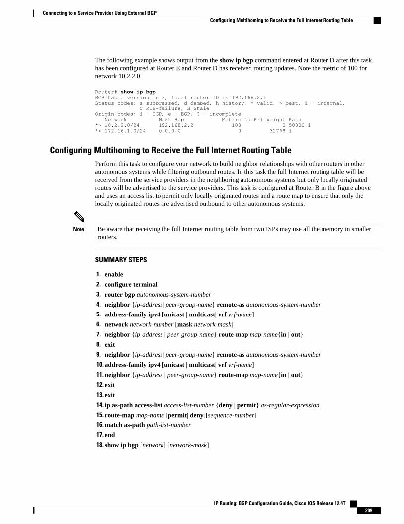
The following example shows output from the show ip bgp command entered at Router D after this taskhas been configured at Router E and Router D has received routing updates. Note the metric of 100 fornetwork 10.2.2.0.
Router# show ip bgpBGP table version is 3, local router ID is 192.168.2.1Status codes: s suppressed, d damped, h history, * valid, > best, i - internal, r RIB-failure, S StaleOrigin codes: i - IGP, e - EGP, ? - incomplete Network Next Hop Metric LocPrf Weight Path*> 10.2.2.0/24 192.168.2.2 100 0 50000 i*> 172.16.1.0/24 0.0.0.0 0 32768 i
Configuring Multihoming to Receive the Full Internet Routing TablePerform this task to configure your network to build neighbor relationships with other routers in otherautonomous systems while filtering outbound routes. In this task the full Internet routing table will bereceived from the service providers in the neighboring autonomous systems but only locally originatedroutes will be advertised to the service providers. This task is configured at Router B in the figure aboveand uses an access list to permit only locally originated routes and a route map to ensure that only thelocally originated routes are advertised outbound to other autonomous systems.
Note Be aware that receiving the full Internet routing table from two ISPs may use all the memory in smallerrouters.
SUMMARY STEPS
1. enable
2. configure terminal
3. router bgp autonomous-system-number
4. neighbor {ip-address| peer-group-name} remote-as autonomous-system-number
5. address-family ipv4 [unicast | multicast| vrf vrf-name]
6. network network-number [mask network-mask]
7. neighbor {ip-address | peer-group-name} route-map map-name{in | out}
8. exit
9. neighbor {ip-address| peer-group-name} remote-as autonomous-system-number
10. address-family ipv4 [unicast | multicast| vrf vrf-name]
11. neighbor {ip-address | peer-group-name} route-map map-name{in | out}
12. exit
13. exit
14. ip as-path access-list access-list-number {deny | permit} as-regular-expression
15. route-map map-name [permit| deny][sequence-number]
16. match as-path path-list-number
17. end
18. show ip bgp [network] [network-mask]
Connecting to a Service Provider Using External BGPConfiguring Multihoming to Receive the Full Internet Routing Table
IP Routing: BGP Configuration Guide, Cisco IOS Release 12.4T 209
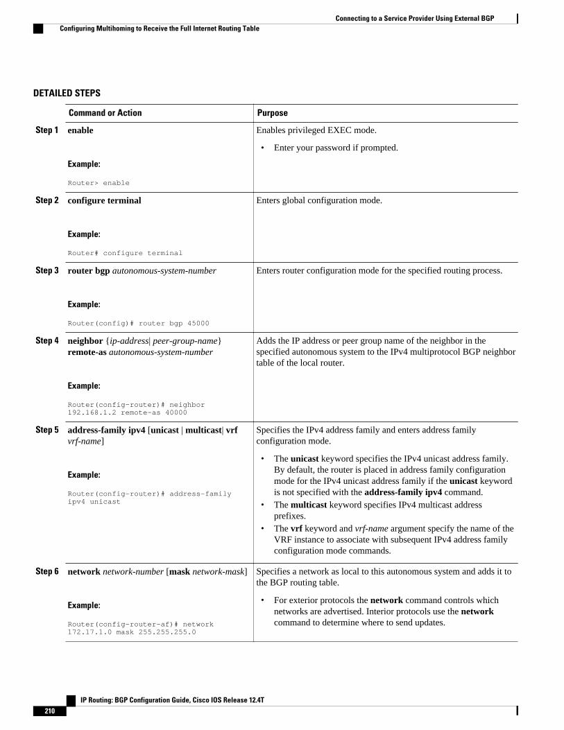
DETAILED STEPS
Command or Action Purpose
Step 1 enable
Example:
Router> enable
Enables privileged EXEC mode.
• Enter your password if prompted.
Step 2 configure terminal
Example:
Router# configure terminal
Enters global configuration mode.
Step 3 router bgp autonomous-system-number
Example:
Router(config)# router bgp 45000
Enters router configuration mode for the specified routing process.
Step 4 neighbor {ip-address| peer-group-name}remote-as autonomous-system-number
Example:
Router(config-router)# neighbor 192.168.1.2 remote-as 40000
Adds the IP address or peer group name of the neighbor in thespecified autonomous system to the IPv4 multiprotocol BGP neighbortable of the local router.
Step 5 address-family ipv4 [unicast | multicast| vrfvrf-name]
Example:
Router(config-router)# address-family ipv4 unicast
Specifies the IPv4 address family and enters address familyconfiguration mode.
• The unicast keyword specifies the IPv4 unicast address family.By default, the router is placed in address family configurationmode for the IPv4 unicast address family if the unicast keywordis not specified with the address-family ipv4 command.
• The multicast keyword specifies IPv4 multicast addressprefixes.
• The vrf keyword and vrf-name argument specify the name of theVRF instance to associate with subsequent IPv4 address familyconfiguration mode commands.
Step 6 network network-number [mask network-mask]
Example:
Router(config-router-af)# network 172.17.1.0 mask 255.255.255.0
Specifies a network as local to this autonomous system and adds it tothe BGP routing table.
• For exterior protocols the network command controls whichnetworks are advertised. Interior protocols use the networkcommand to determine where to send updates.
Connecting to a Service Provider Using External BGP Configuring Multihoming to Receive the Full Internet Routing Table
IP Routing: BGP Configuration Guide, Cisco IOS Release 12.4T210

Command or Action Purpose
Step 7 neighbor {ip-address | peer-group-name} route-map map-name{in | out}
Example:
Router(config-router-af)# neighbor 192.168.1.2 route-map localonly out
Applies a route map to incoming or outgoing routes.
• In this example, the route map named localonly is applied tooutbound routes to Router A.
Step 8 exit
Example:
Router(config-router-af)# exit
Exits address family configuration mode and enters routerconfiguration mode.
Step 9 neighbor {ip-address| peer-group-name}remote-as autonomous-system-number
Example:
Router(config-router)# neighbor 192.168.3.2 remote-as 50000
Adds the IP address or peer group name of the neighbor in thespecified autonomous system to the IPv4 multiprotocol BGP neighbortable of the local router.
Step 10 address-family ipv4 [unicast | multicast| vrfvrf-name]
Example:
Router(config-router)# address-family ipv4 unicast
Specifies the IPv4 address family and enters address familyconfiguration mode.
• The unicast keyword specifies the IPv4 unicast address family.By default, the router is placed in address family configurationmode for the IPv4 unicast address family if the unicast keywordis not specified with the address-family ipv4 command.
• The multicast keyword specifies IPv4 multicast addressprefixes.
The vrf keyword and vrf-name argument specify the name of theVRF instance to associate with subsequent IPv4 address familyconfiguration mode commands.
Step 11 neighbor {ip-address | peer-group-name} route-map map-name{in | out}
Example:
Router(config-router-af)# neighbor 192.168.3.2 route-map localonly out
Applies a route map to incoming or outgoing routes.
• In this example, the route map named localonly is applied tooutbound routes to Router E.
Connecting to a Service Provider Using External BGPConfiguring Multihoming to Receive the Full Internet Routing Table
IP Routing: BGP Configuration Guide, Cisco IOS Release 12.4T 211

Command or Action Purpose
Step 12 exit
Example:
Router(config-router-af)# exit
Exits address family configuration mode and enters routerconfiguration mode.
Step 13 exit
Example:
Router(config-router)# exit
Exits router configuration mode and enters global configurationmode.
Step 14 ip as-path access-list access-list-number {deny |permit} as-regular-expression
Example:
Router(config)# ip as-path access-list 10 permit ^$
Defines a BGP-related access list.
• In this example, the access list number 10 is defined to permitonly locally originated BGP routes.
Step 15 route-map map-name [permit| deny][sequence-number]
Example:
Router(config)# route-map localonly permit 10
Configures a route map and enters route map configuration mode.
• In this example, a route map named localonly is created.
Step 16 match as-path path-list-number
Example:
Router(config-route-map)# match as-path 10
Matches a BGP autonomous system path access list.
• In this example, the BGP autonomous system path access listcreated in Step 12 is used for the match clause.
Step 17 end
Example:
Router(config-route-map)# end
Exits route map configuration mode and enters privileged EXECmode.
Step 18 show ip bgp [network] [network-mask]
Example:
Router# show ip bgp
Displays the entries in the BGP routing table.
Note Only the syntax applicable to this task is used in this example.For more details, see the Cisco IOS IP Routing: BGPCommand Reference.
Connecting to a Service Provider Using External BGP Configuring Multihoming to Receive the Full Internet Routing Table
IP Routing: BGP Configuration Guide, Cisco IOS Release 12.4T212

ExamplesThe following example shows the BGP routing table for Router B in the figure above after this task hasbeen configured. Note that the routing table contains the information about the networks in the autonomoussystems 40000 and 50000.
BGP table version is 5, local router ID is 172.17.1.99Status codes: s suppressed, d damped, h history, * valid, > best, i - internal, r RIB-failure, S StaleOrigin codes: i - IGP, e - EGP, ? - incomplete Network Next Hop Metric LocPrf Weight Path*> 10.1.1.0/24 192.168.1.2 0 0 40000 i*> 10.2.2.0/24 192.168.3.2 0 0 50000 i*> 172.17.1.0/24 0.0.0.0 0 32768 i
Configuring BGP PoliciesThe tasks in this section help you configure BGP policies that filter the traffic in your BGP network. Thefollowing optional tasks demonstrate some of the various methods by which traffic can be filtered in yourBGP network:
• Filtering BGP Prefixes with Prefix Lists, page 213• Filtering BGP Prefixes with AS-path Filters, page 217• Filtering BGP Prefixes with AS-path Filters Using 4-Byte Autonomous System Numbers, page 220• Filtering Traffic Using Community Lists, page 224• Filtering Traffic Using Extended Community Lists, page 229• Filtering Traffic Using a BGP Route Map Policy List, page 233• Filtering Traffic Using Continue Clauses in a BGP Route Map, page 237
Filtering BGP Prefixes with Prefix ListsPerform this task to use prefix lists to filter BGP route information. The task is configured at Router B inthe figure below where both Router A and Router E are set up as BGP peers. A prefix list is configured topermit only routes from the network 10.2.2.0/24 to be outbound. In effect, this will restrict the informationthat is received from Router E to be forwarded to Router A. Optional steps are included to display theprefix list information and to reset the hit count.
Figure 21 BGP Topology for Configuring BGP Policies Tasks
Configuring BGP PoliciesFiltering BGP Prefixes with Prefix Lists
IP Routing: BGP Configuration Guide, Cisco IOS Release 12.4T 213

Note The neighbor prefix-list and the neighbor distribute-list commands are mutually exclusive for a BGPpeer.
>
SUMMARY STEPS
1. enable
2. configure terminal
3. router bgp autonomous-system-number
4. neighbor ip-address remote-as autonomous-system-number
5. Repeat Step 5 for all BGP peers.
6. address-family ipv4 [unicast | multicast| vrf vrf-name]
7. network network-number [mask network-mask]
8. aggregate-address address mask [as-set]
9. neighbor ip-address prefix-list list-name {in | out}
10. exit
11. exit
12. ip prefix-list list-name [seq seq-number] {deny network / length| permit network / length}[ge ge-value] [le le-value] [eq eq-value]
13. end
14. show ip prefix-list [detail | summary] [prefix-list-name [seq seq-number | network / length [longer |first-match]]]
15. clear ip prefix-list {*| ip-address| peer-group-name} out
DETAILED STEPS
Command or Action Purpose
Step 1 enable
Example:
Router> enable
Enables privileged EXEC mode.
• Enter your password if prompted.
Step 2 configure terminal
Example:
Router# configure terminal
Enters global configuration mode.
Connecting to a Service Provider Using External BGP Filtering BGP Prefixes with Prefix Lists
IP Routing: BGP Configuration Guide, Cisco IOS Release 12.4T214

Command or Action Purpose
Step 3 router bgp autonomous-system-number
Example:
Router(config)# router bgp 45000
Enters router configuration mode for the specified routing process.
Step 4 neighbor ip-address remote-as autonomous-system-number
Example:
Router(config-router)# neighbor 192.168.1.2 remote-as 40000
Adds the IP address of the neighbor in the specified autonomoussystem to the BGP neighbor table of the local router.
Step 5 Repeat Step 5 for all BGP peers. --
Step 6 address-family ipv4 [unicast | multicast| vrfvrf-name]
Example:
Router(config-router)# address-family ipv4 unicast
Specifies the IPv4 address family and enters address familyconfiguration mode.
• The unicast keyword specifies the IPv4 unicast address family.By default, the router is placed in address family configurationmode for the IPv4 unicast address family if the unicast keywordis not specified with the address-family ipv4 command.
• The multicast keyword specifies IPv4 multicast addressprefixes.
• The vrf keyword and vrf-name argument specify the name of theVRF instance to associate with subsequent IPv4 address familyconfiguration mode commands.
Step 7 network network-number [mask network-mask]
Example:
Router(config-router-af)# network 172.17.1.0 mask 255.255.255.0
(Optional) Specifies a network as local to this autonomous system andadds it to the BGP routing table.
• For exterior protocols the network command controls whichnetworks are advertised. Interior protocols use the networkcommand to determine where to send updates.
Step 8 aggregate-address address mask [as-set]
Example:
Router(config-router-af)# aggregate-address 172.0.0.0 255.0.0.0
Creates an aggregate entry in a BGP routing table.
• A specified route must exist in the BGP table.• Use the aggregate-address command with no keywords to
create an aggregate entry if any more-specific BGP routes areavailable that fall in the specified range.
Note Only partial syntax is used in this example. For more details,see the Cisco IOS IP Routing: BGP Command Reference.
Connecting to a Service Provider Using External BGPFiltering BGP Prefixes with Prefix Lists
IP Routing: BGP Configuration Guide, Cisco IOS Release 12.4T 215

Command or Action Purpose
Step 9 neighbor ip-address prefix-list list-name {in |out}
Example:
Router(config-router-af)# neighbor 192.168.1.2 prefix-list super172 out
Distributes BGP neighbor information as specified in a prefix list.
• In this example, a prefix list called super172 is set for outgoingroutes to Router A.
Step 10 exit
Example:
Router(config-router-af)# exit
Exits address family configuration mode and enters routerconfiguration mode.
Step 11 exit
Example:
Router(config-router) exit
Exits router configuration mode and enters global configurationmode.
Step 12 ip prefix-list list-name [seq seq-number] {denynetwork / length| permit network / length}[ge ge-value] [le le-value] [eq eq-value]
Example:
Router(config)# ip prefix-list super172 permit 172.0.0.0/8
Defines a BGP-related prefix list and enters access list configurationmode.
• In this example, the prefix list called super172 is defined topermit only route 172.0.0.0/8 to be forwarded.
• All other routes will be denied because there is an implicit denyat the end of all prefix lists.
Step 13 end
Example:
Router(config-access-list)# end
Exits access list configuration mode and enters privileged EXECmode.
Step 14 show ip prefix-list [detail | summary] [prefix-list-name [seq seq-number | network / length[longer | first-match]]]
Example:
Router# show ip prefix-list detail super172
Displays information about prefix lists.
• In this example, details of the prefix list named super172 will bedisplayed, including the hit count. Hit count is the number oftimes the entry has matched a route.
Connecting to a Service Provider Using External BGP Filtering BGP Prefixes with Prefix Lists
IP Routing: BGP Configuration Guide, Cisco IOS Release 12.4T216

Command or Action Purpose
Step 15 clear ip prefix-list {*| ip-address| peer-group-name} out
Example:
Router# clear ip prefix-list super172 out
Resets the hit count of the prefix list entries.
• In this example, the hit count for the prefix list called super172will be reset.
Examples
The following output from the show ip prefix-list command shows details of the prefix list namedsuper172, including the hit count. The clear ip prefix-listcommand is entered to reset the hit count and theshow ip prefix-list command is entered again to show the hit count reset to 0.
Router# show ip prefix-list detail super172ip prefix-list super172: count: 1, range entries: 0, sequences: 5 - 5, refcount: 4 seq 5 permit 172.0.0.0/8 (hit count: 1, refcount: 1)Router# clear ip prefix-list super172Router# show ip prefix-list detail super172ip prefix-list super172: count: 1, range entries: 0, sequences: 5 - 5, refcount: 4 seq 5 permit 172.0.0.0/8 (hit count: 0, refcount: 1)
Filtering BGP Prefixes with AS-path FiltersPerform this task to filter BGP prefixes using AS-path filters with an access list based on the value of theAS-path attribute to filter route information. An AS-path access list is configured at Router B in the figureabove. The first line of the access list denies all matches to the AS-path 50000 and the second line allowsall other paths. The router uses the neighbor filter-list command to specify the AS-path access list as anoutbound filter. After the filtering is enabled, traffic can be received from both Router A and Router C butupdates originating from autonomous system 50000 (Router C) are not forwarded by Router B to Router A.If any updates from Router C originated from another autonomous system, they would be forwardedbecause they would contain both autonomous system 50000 plus another autonomous system number, andthat would not match the AS-path access list.
Note In Cisco IOS Releases 12.0(22)S, 12.2(15)T, 12.2(18)S, and later releases, the maximum number ofautonomous system access lists that can be configured with the ip as-path access-list command isincreased from 199 to 500.
Connecting to a Service Provider Using External BGPFiltering BGP Prefixes with AS-path Filters
IP Routing: BGP Configuration Guide, Cisco IOS Release 12.4T 217
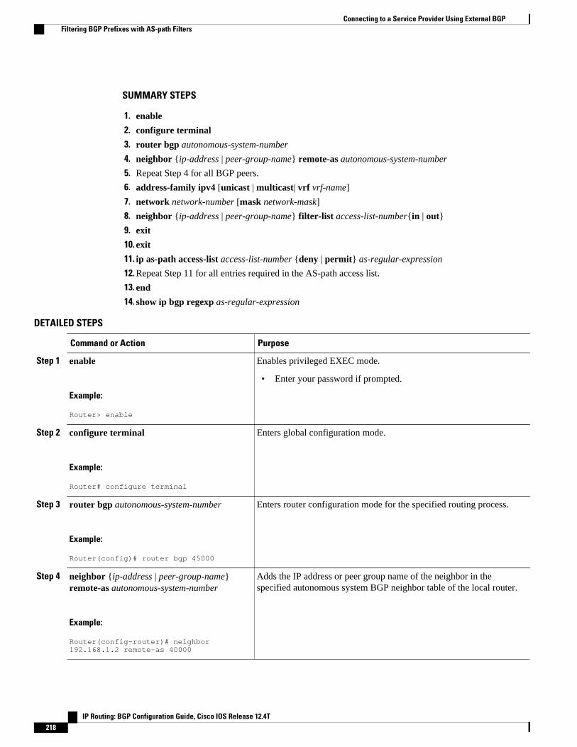
SUMMARY STEPS
1. enable
2. configure terminal
3. router bgp autonomous-system-number
4. neighbor {ip-address | peer-group-name} remote-as autonomous-system-number
5. Repeat Step 4 for all BGP peers.
6. address-family ipv4 [unicast | multicast| vrf vrf-name]
7. network network-number [mask network-mask]
8. neighbor {ip-address | peer-group-name} filter-list access-list-number{in | out}
9. exit
10. exit
11. ip as-path access-list access-list-number {deny | permit} as-regular-expression
12. Repeat Step 11 for all entries required in the AS-path access list.
13. end
14. show ip bgp regexp as-regular-expression
DETAILED STEPS
Command or Action Purpose
Step 1 enable
Example:
Router> enable
Enables privileged EXEC mode.
• Enter your password if prompted.
Step 2 configure terminal
Example:
Router# configure terminal
Enters global configuration mode.
Step 3 router bgp autonomous-system-number
Example:
Router(config)# router bgp 45000
Enters router configuration mode for the specified routing process.
Step 4 neighbor {ip-address | peer-group-name}remote-as autonomous-system-number
Example:
Router(config-router)# neighbor 192.168.1.2 remote-as 40000
Adds the IP address or peer group name of the neighbor in thespecified autonomous system BGP neighbor table of the local router.
Connecting to a Service Provider Using External BGP Filtering BGP Prefixes with AS-path Filters
IP Routing: BGP Configuration Guide, Cisco IOS Release 12.4T218
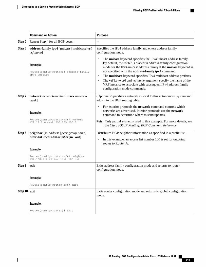
Command or Action Purpose
Step 5 Repeat Step 4 for all BGP peers. --
Step 6 address-family ipv4 [unicast | multicast| vrfvrf-name]
Example:
Router(config-router)# address-family ipv4 unicast
Specifies the IPv4 address family and enters address familyconfiguration mode.
• The unicast keyword specifies the IPv4 unicast address family.By default, the router is placed in address family configurationmode for the IPv4 unicast address family if the unicast keyword isnot specified with the address-family ipv4 command.
• The multicast keyword specifies IPv4 multicast address prefixes.• The vrf keyword and vrf-name argument specify the name of the
VRF instance to associate with subsequent IPv4 address familyconfiguration mode commands.
Step 7 network network-number [mask network-mask]
Example:
Router(config-router-af)# network 172.17.1.0 mask 255.255.255.0
(Optional) Specifies a network as local to this autonomous system andadds it to the BGP routing table.
• For exterior protocols the network command controls whichnetworks are advertised. Interior protocols use the networkcommand to determine where to send updates.
Note Only partial syntax is used in this example. For more details, seethe Cisco IOS IP Routing: BGP Command Reference.
Step 8 neighbor {ip-address | peer-group-name}filter-list access-list-number{in | out}
Example:
Router(config-router-af)# neighbor 192.168.1.2 filter-list 100 out
Distributes BGP neighbor information as specified in a prefix list.
• In this example, an access list number 100 is set for outgoingroutes to Router A.
Step 9 exit
Example:
Router(config-router-af)# exit
Exits address family configuration mode and returns to routerconfiguration mode.
Step 10 exit
Example:
Router(config-router)# exit
Exits router configuration mode and returns to global configurationmode.
Connecting to a Service Provider Using External BGPFiltering BGP Prefixes with AS-path Filters
IP Routing: BGP Configuration Guide, Cisco IOS Release 12.4T 219
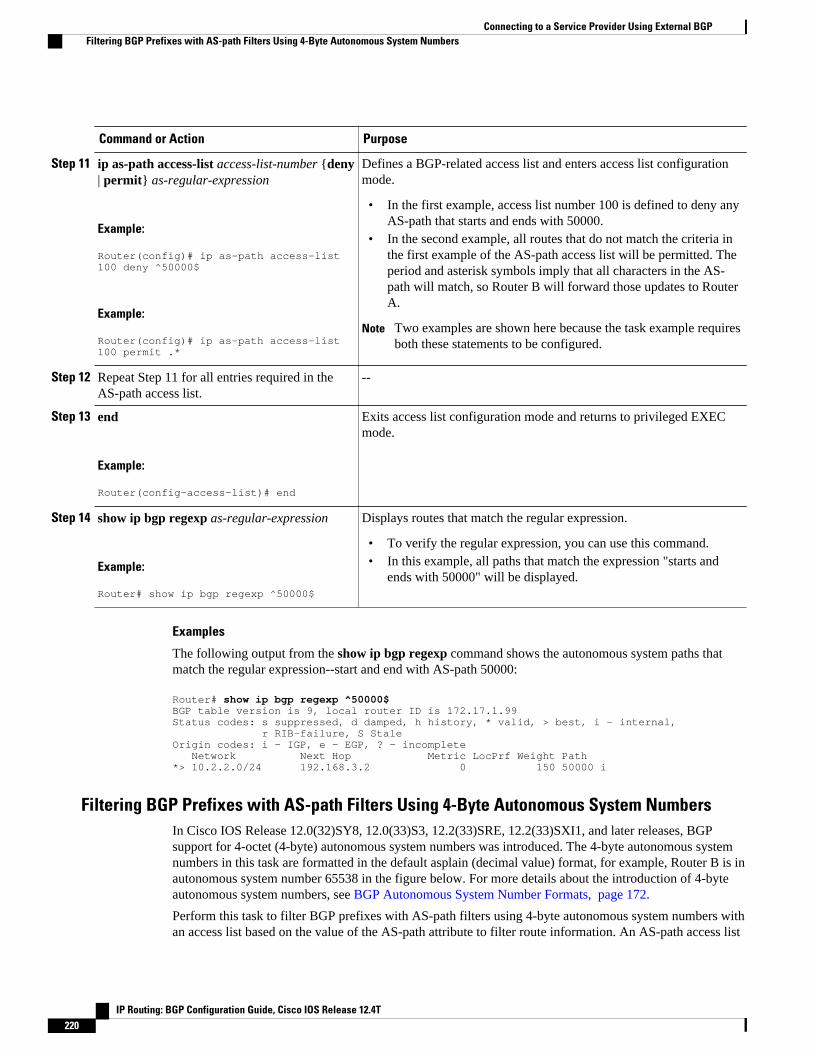
Command or Action Purpose
Step 11 ip as-path access-list access-list-number {deny| permit} as-regular-expression
Example:
Router(config)# ip as-path access-list 100 deny ^50000$
Example:
Router(config)# ip as-path access-list 100 permit .*
Defines a BGP-related access list and enters access list configurationmode.
• In the first example, access list number 100 is defined to deny anyAS-path that starts and ends with 50000.
• In the second example, all routes that do not match the criteria inthe first example of the AS-path access list will be permitted. Theperiod and asterisk symbols imply that all characters in the AS-path will match, so Router B will forward those updates to RouterA.
Note Two examples are shown here because the task example requiresboth these statements to be configured.
Step 12 Repeat Step 11 for all entries required in theAS-path access list.
--
Step 13 end
Example:
Router(config-access-list)# end
Exits access list configuration mode and returns to privileged EXECmode.
Step 14 show ip bgp regexp as-regular-expression
Example:
Router# show ip bgp regexp ^50000$
Displays routes that match the regular expression.
• To verify the regular expression, you can use this command.• In this example, all paths that match the expression "starts and
ends with 50000" will be displayed.
Examples
The following output from the show ip bgp regexp command shows the autonomous system paths thatmatch the regular expression--start and end with AS-path 50000:
Router# show ip bgp regexp ^50000$BGP table version is 9, local router ID is 172.17.1.99Status codes: s suppressed, d damped, h history, * valid, > best, i - internal, r RIB-failure, S StaleOrigin codes: i - IGP, e - EGP, ? - incomplete Network Next Hop Metric LocPrf Weight Path*> 10.2.2.0/24 192.168.3.2 0 150 50000 i
Filtering BGP Prefixes with AS-path Filters Using 4-Byte Autonomous System NumbersIn Cisco IOS Release 12.0(32)SY8, 12.0(33)S3, 12.2(33)SRE, 12.2(33)SXI1, and later releases, BGPsupport for 4-octet (4-byte) autonomous system numbers was introduced. The 4-byte autonomous systemnumbers in this task are formatted in the default asplain (decimal value) format, for example, Router B is inautonomous system number 65538 in the figure below. For more details about the introduction of 4-byteautonomous system numbers, see BGP Autonomous System Number Formats, page 172.
Perform this task to filter BGP prefixes with AS-path filters using 4-byte autonomous system numbers withan access list based on the value of the AS-path attribute to filter route information. An AS-path access list
Connecting to a Service Provider Using External BGP Filtering BGP Prefixes with AS-path Filters Using 4-Byte Autonomous System Numbers
IP Routing: BGP Configuration Guide, Cisco IOS Release 12.4T220

is configured at Router B in the figure below. The first line of the access list denies all matches to the AS-path 65550 and the second line allows all other paths. The router uses the neighbor filter-list command tospecify the AS-path access list as an outbound filter. After the filtering is enabled, traffic can be receivedfrom both Router A and Router E but updates originating from autonomous system 65550 (Router E) arenot forwarded by Router B to Router A. If any updates from Router E originated from another autonomoussystem, they would be forwarded because they would contain both autonomous system 65550 plus anotherautonomous system number, and that would not match the AS-path access list.
Note In Cisco IOS Releases 12.0(22)S, 12.2(15)T, 12.2(18)S, and later releases, the maximum number ofautonomous system access lists that can be configured with the ip as-path access-list command isincreased from 199 to 500.
Figure 22 BGP Topology for Filtering BGP Prefixes with AS-path Filters Using 4-Byte Autonomous SystemNumbers
Connecting to a Service Provider Using External BGPFiltering BGP Prefixes with AS-path Filters Using 4-Byte Autonomous System Numbers
IP Routing: BGP Configuration Guide, Cisco IOS Release 12.4T 221

SUMMARY STEPS
1. enable
2. configure terminal
3. router bgp autonomous-system-number
4. neighbor {ip-address | peer-group-name} remote-as autonomous-system-number
5. Repeat Step 4 for all BGP peers.
6. address-family ipv4 [unicast | multicast| vrf vrf-name]
7. network network-number [mask network-mask]
8. neighbor {ip-address | peer-group-name} filter-list access-list-number{in | out}
9. exit
10. exit
11. ip as-path access-list access-list-number {deny | permit} as-regular-expression
12. Repeat Step 11 for all entries required in the AS-path access list.
13. end
14. show ip bgp regexp as-regular-expression
DETAILED STEPS
Command or Action Purpose
Step 1 enable
Example:
Router> enable
Enables privileged EXEC mode.
• Enter your password if prompted.
Step 2 configure terminal
Example:
Router# configure terminal
Enters global configuration mode.
Step 3 router bgp autonomous-system-number
Example:
Router(config)# router bgp 65538
Enters router configuration mode for the specified routing process.
Step 4 neighbor {ip-address | peer-group-name}remote-as autonomous-system-number
Example:
Router(config-router-af)# neighbor 192.168.1.2 remote-as 65536
Adds the IP address or peer group name of the neighbor in the specifiedautonomous system BGP neighbor table of the local router.
• In this example, the IP address for the neighbor at Router A isadded.
Connecting to a Service Provider Using External BGP Filtering BGP Prefixes with AS-path Filters Using 4-Byte Autonomous System Numbers
IP Routing: BGP Configuration Guide, Cisco IOS Release 12.4T222

Command or Action Purpose
Step 5 Repeat Step 4 for all BGP peers. --
Step 6 address-family ipv4 [unicast | multicast| vrfvrf-name]
Example:
Router(config-router)# address-family ipv4 unicast
Specifies the IPv4 address family and enters address familyconfiguration mode.
• The unicast keyword specifies the IPv4 unicast address family. Bydefault, the router is placed in address family configuration modefor the IPv4 unicast address family if the unicast keyword is notspecified with the address-family ipv4 command.
• The multicast keyword specifies IPv4 multicast address prefixes.• The vrf keyword and vrf-name argument specify the name of the
VRF instance to associate with subsequent IPv4 address familyconfiguration mode commands.
Step 7 network network-number [mask network-mask]
Example:
Router(config-router-af)# network 172.17.1.0 mask 255.255.255.0
(Optional) Specifies a network as local to this autonomous system andadds it to the BGP routing table.
• For exterior protocols the network command controls whichnetworks are advertised. Interior protocols use the networkcommand to determine where to send updates.
Note Only partial syntax is used in this example. For more details, seethe Cisco IOS IP Routing: BGP Command Reference.
Step 8 neighbor {ip-address | peer-group-name}filter-list access-list-number{in | out}
Example:
Router(config-router-af)# neighbor 192.168.1.2 filter-list 99 out
Distributes BGP neighbor information as specified in a prefix list.
• In this example, an access list number 99 is set for outgoing routesto Router A.
Step 9 exit
Example:
Router(config-router-af)# exit
Exits address family configuration mode and returns to routerconfiguration mode.
Step 10 exit
Example:
Router(config-router)# exit
Exits router configuration mode and returns to global configurationmode.
Connecting to a Service Provider Using External BGPFiltering BGP Prefixes with AS-path Filters Using 4-Byte Autonomous System Numbers
IP Routing: BGP Configuration Guide, Cisco IOS Release 12.4T 223

Command or Action Purpose
Step 11 ip as-path access-list access-list-number{deny | permit} as-regular-expression
Example:
Router(config)# ip as-path access-list 99 deny ^65550$
Example:
and
Example:
Router(config)# ip as-path access-list 99 permit .*
Defines a BGP-related access list and enters access list configurationmode.
• In the first example, access list number 99 is defined to deny anyAS-path that starts and ends with 65550.
• In the second example, all routes that do not match the criteria inthe first example of the AS-path access list will be permitted. Theperiod and asterisk symbols imply that all characters in the AS-path will match, so Router B will forward those updates to RouterA.
Note Two examples are shown here because the task example requiresboth these statements to be configured.
Step 12 Repeat Step 11 for all entries required in theAS-path access list.
--
Step 13 end
Example:
Router(config-access-list)# end
Exits access list configuration mode and returns to privileged EXECmode.
Step 14 show ip bgp regexp as-regular-expression
Example:
Router# show ip bgp regexp ^65550$
Displays routes that match the regular expression.
• To verify the regular expression, you can use this command.• In this example, all paths that match the expression "starts and
ends with 65550" will be displayed.
Examples
The following output from the show ip bgp regexp command shows the autonomous system paths thatmatch the regular expression--start and end with AS-path 65550:
RouterB# show ip bgp regexp ^65550$BGP table version is 4, local router ID is 172.17.1.99Status codes: s suppressed, d damped, h history, * valid, > best, i - internal, r RIB-failure, S StaleOrigin codes: i - IGP, e - EGP, ? - incomplete Network Next Hop Metric LocPrf Weight Path*> 10.2.2.0/24 192.168.3.2 0 0 65550 i
Filtering Traffic Using Community ListsPerform this task to filter traffic by creating BGP community lists and then reference them within a routemap to control incoming routes. BGP communities provide a method of filtering inbound or outboundroutes for large, complex networks. Instead of compiling long access or prefix lists of individual peers,
Connecting to a Service Provider Using External BGP Filtering Traffic Using Community Lists
IP Routing: BGP Configuration Guide, Cisco IOS Release 12.4T224

BGP allows grouping of peers with identical routing policies even though they reside in differentautonomous systems or networks.
In this task, Router B in the figure above is configured with several route maps and community lists tocontrol incoming routes.
SUMMARY STEPS
1. enable
2. configure terminal
3. router bgp autonomous-system-number
4. neighbor {ip-address | peer-group-name} remote-as autonomous-system-number
5. address-family ipv4 [unicast | multicast| vrf vrf-name]
6. neighbor {ip-address | peer-group-name} route-map route-map-name{in | out}
7. exit
8. exit
9. route-map map-name [permit | deny] [sequence-number]
10. match community {standard-list-number | expanded-list-number | community-list-name [exact]}
11. set weight weight
12. exit
13. route-map map-name [permit | deny] [sequence-number]
14. match community {standard-list-number | expanded-list-number | community-list-name [exact]}
15. set community community-number
16. exit
17. ip community-list {standard-list-number| standard list-name {deny | permit} [community-number][AA:NN] [internet] [local-AS] [no-advertise] [no-export]} | {expanded-list-number | expanded list-name {deny | permit} regular-expression}
18. Repeat Step 15 to create all the required community lists.
19. exit
20. show ip community-list [standard-list-number | expanded-list-number | community-list-name][exact-match]
DETAILED STEPS
Command or Action Purpose
Step 1 enable
Example:
Router> enable
Enables privileged EXEC mode.
• Enter your password if prompted.
Step 2 configure terminal
Example:
Router# configure terminal
Enters global configuration mode.
Connecting to a Service Provider Using External BGPFiltering Traffic Using Community Lists
IP Routing: BGP Configuration Guide, Cisco IOS Release 12.4T 225
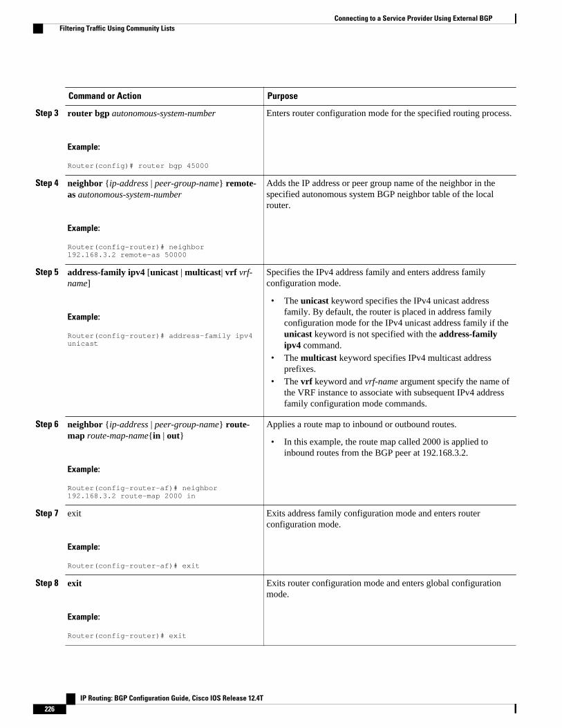
Command or Action Purpose
Step 3 router bgp autonomous-system-number
Example:
Router(config)# router bgp 45000
Enters router configuration mode for the specified routing process.
Step 4 neighbor {ip-address | peer-group-name} remote-as autonomous-system-number
Example:
Router(config-router)# neighbor 192.168.3.2 remote-as 50000
Adds the IP address or peer group name of the neighbor in thespecified autonomous system BGP neighbor table of the localrouter.
Step 5 address-family ipv4 [unicast | multicast| vrf vrf-name]
Example:
Router(config-router)# address-family ipv4 unicast
Specifies the IPv4 address family and enters address familyconfiguration mode.
• The unicast keyword specifies the IPv4 unicast addressfamily. By default, the router is placed in address familyconfiguration mode for the IPv4 unicast address family if theunicast keyword is not specified with the address-familyipv4 command.
• The multicast keyword specifies IPv4 multicast addressprefixes.
• The vrf keyword and vrf-name argument specify the name ofthe VRF instance to associate with subsequent IPv4 addressfamily configuration mode commands.
Step 6 neighbor {ip-address | peer-group-name} route-map route-map-name{in | out}
Example:
Router(config-router-af)# neighbor 192.168.3.2 route-map 2000 in
Applies a route map to inbound or outbound routes.
• In this example, the route map called 2000 is applied toinbound routes from the BGP peer at 192.168.3.2.
Step 7 exit
Example:
Router(config-router-af)# exit
Exits address family configuration mode and enters routerconfiguration mode.
Step 8 exit
Example:
Router(config-router)# exit
Exits router configuration mode and enters global configurationmode.
Connecting to a Service Provider Using External BGP Filtering Traffic Using Community Lists
IP Routing: BGP Configuration Guide, Cisco IOS Release 12.4T226

Command or Action Purpose
Step 9 route-map map-name [permit | deny] [sequence-number]
Example:
Router(config)# route-map 2000 permit 10
Creates a route map and enters route map configuration mode.
• In this example, the route map called 2000 is defined.
Step 10 match community {standard-list-number |expanded-list-number | community-list-name[exact]}
Example:
Router(config-route-map)# match community 1
Matches a BGP community list.
• In this example, the community attribute is matched tocommunity list 1.
Step 11 set weight weight
Example:
Router(config-route-map)# set weight 30
Specifies the BGP weight for the routing table.
• In this example, any route that matches community list 1 willhave the BGP weight set to 30.
Step 12 exit
Example:
Router(config-route-map)# exit
Exits route map configuration mode and enters globalconfiguration mode.
Step 13 route-map map-name [permit | deny] [sequence-number]
Example:
Router(config)# route-map 3000 permit 10
Creates a route map and enters route map configuration mode.
• In this example, the route map called 3000 is defined.
Step 14 match community {standard-list-number |expanded-list-number | community-list-name[exact]}
Example:
Router(config-route-map)# match community 2
Matches a BGP community list.
• In this example, the community attribute is matched tocommunity list 2.
Connecting to a Service Provider Using External BGPFiltering Traffic Using Community Lists
IP Routing: BGP Configuration Guide, Cisco IOS Release 12.4T 227

Command or Action Purpose
Step 15 set community community-number
Example:
Router(config-route-map)# set community 99
Sets the BGP communities attribute.
• In this example, any route that matches community list 2 willhave the BGP community attribute set to 99.
Step 16 exit
Example:
Router(config-route-map)# exit
Exits route map configuration mode and enters globalconfiguration mode.
Step 17 ip community-list {standard-list-number| standardlist-name {deny | permit} [community-number][AA:NN] [internet] [local-AS] [no-advertise] [no-export]} | {expanded-list-number | expanded list-name {deny | permit} regular-expression}
Example:
Router(config)# ip community-list 1 permit 100
Example:
and
Example:
Router(config)# ip community-list 2 permit internet
Creates a community list for BGP and controls access to it.
• In the first example, community list 1 permits routes with acommunity attribute of 100. Router C routes all havecommunity attribute of 100 so their weight will be set to 30.
• In the second example, community list 2 effectively permitsall routes by using the internetkeyword. Any routes that didnot match community list 1 are checked against communitylist 2. All routes are permitted but no changes are made to theroute attributes.
Note Two examples are shown here because the task examplerequires both these statements to be configured.
Step 18 Repeat Step 15 to create all the required communitylists.
--
Step 19 exit
Example:
Router(config)# exit
Exits global configuration mode and enters privileged EXECmode.
Connecting to a Service Provider Using External BGP Filtering Traffic Using Community Lists
IP Routing: BGP Configuration Guide, Cisco IOS Release 12.4T228
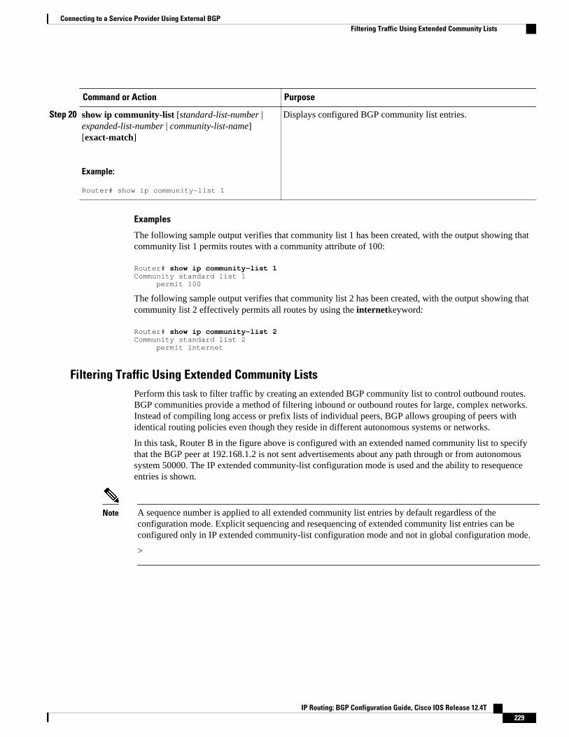
Command or Action Purpose
Step 20 show ip community-list [standard-list-number |expanded-list-number | community-list-name][exact-match]
Example:
Router# show ip community-list 1
Displays configured BGP community list entries.
Examples
The following sample output verifies that community list 1 has been created, with the output showing thatcommunity list 1 permits routes with a community attribute of 100:
Router# show ip community-list 1Community standard list 1 permit 100
The following sample output verifies that community list 2 has been created, with the output showing thatcommunity list 2 effectively permits all routes by using the internetkeyword:
Router# show ip community-list 2Community standard list 2 permit internet
Filtering Traffic Using Extended Community ListsPerform this task to filter traffic by creating an extended BGP community list to control outbound routes.BGP communities provide a method of filtering inbound or outbound routes for large, complex networks.Instead of compiling long access or prefix lists of individual peers, BGP allows grouping of peers withidentical routing policies even though they reside in different autonomous systems or networks.
In this task, Router B in the figure above is configured with an extended named community list to specifythat the BGP peer at 192.168.1.2 is not sent advertisements about any path through or from autonomoussystem 50000. The IP extended community-list configuration mode is used and the ability to resequenceentries is shown.
Note A sequence number is applied to all extended community list entries by default regardless of theconfiguration mode. Explicit sequencing and resequencing of extended community list entries can beconfigured only in IP extended community-list configuration mode and not in global configuration mode.
>
Connecting to a Service Provider Using External BGPFiltering Traffic Using Extended Community Lists
IP Routing: BGP Configuration Guide, Cisco IOS Release 12.4T 229
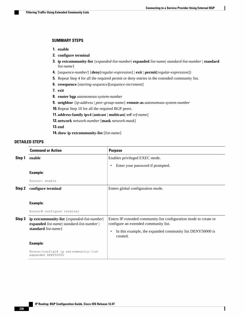
SUMMARY STEPS
1. enable
2. configure terminal
3. ip extcommunity-list {expanded-list-number| expanded list-name| standard-list-number | standardlist-name}
4. [sequence-number] {deny[regular-expression] | exit | permit[regular-expression]}
5. Repeat Step 4 for all the required permit or deny entries in the extended community list.
6. resequence [starting-sequence][sequence-increment]
7. exit
8. router bgp autonomous-system-number
9. neighbor {ip-address | peer-group-name} remote-as autonomous-system-number
10. Repeat Step 10 for all the required BGP peers.
11. address-family ipv4 [unicast | multicast| vrf vrf-name]
12. network network-number [mask network-mask]
13. end
14. show ip extcommunity-list [list-name]
DETAILED STEPS
Command or Action Purpose
Step 1 enable
Example:
Router> enable
Enables privileged EXEC mode.
• Enter your password if prompted.
Step 2 configure terminal
Example:
Router# configure terminal
Enters global configuration mode.
Step 3 ip extcommunity-list {expanded-list-number|expanded list-name| standard-list-number |standard list-name}
Example:
Router(config)# ip extcommunity-list expanded DENY50000
Enters IP extended community-list configuration mode to create orconfigure an extended community list.
• In this example, the expanded community list DENY50000 iscreated.
Connecting to a Service Provider Using External BGP Filtering Traffic Using Extended Community Lists
IP Routing: BGP Configuration Guide, Cisco IOS Release 12.4T230

Command or Action Purpose
Step 4 [sequence-number] {deny[regular-expression]| exit | permit[regular-expression]}
Example:
Router(config-extcomm-list)# 10 deny _50000_
Example:
and
Example:
Router(config-extcomm-list)# 20 deny ^50000 .*
Configures an expanded community list entry.
• In the first example, an expanded community list entry with thesequence number 10 is configured to deny advertisements aboutpaths from autonomous system 50000.
• In the second example, an expanded community list entry with thesequence number 20 is configured to deny advertisements aboutpaths through autonomous system 50000.
Note Two examples are shown here because the task example requiresboth these statements to be configured.
Note Only the syntax applicable to this task is used in this example.For more details, see the Cisco IOS IP Routing: BGP CommandReference.
Step 5 Repeat Step 4 for all the required permit ordeny entries in the extended community list.
--
Step 6 resequence [starting-sequence][sequence-increment]
Example:
Router(config-extcomm-list)# resequence 50 100
Resequences expanded community list entries.
• In this example, the sequence number of the first expandedcommunity list entry is set to 50 and subsequent entries are set toincrement by 100. The second expanded community list entry istherefore set to 150.
Note Only the syntax applicable to this task is used in this example.For more details, see the Cisco IOS IP Routing: BGP CommandReference.
Step 7 exit
Example:
Router(config-extcomm-list)# exit
Exits expanded community-list configuration mode and enters globalconfiguration mode.
Step 8 router bgp autonomous-system-number
Example:
Router(config)# router bgp 45000
Enters router configuration mode for the specified routing process.
Connecting to a Service Provider Using External BGPFiltering Traffic Using Extended Community Lists
IP Routing: BGP Configuration Guide, Cisco IOS Release 12.4T 231
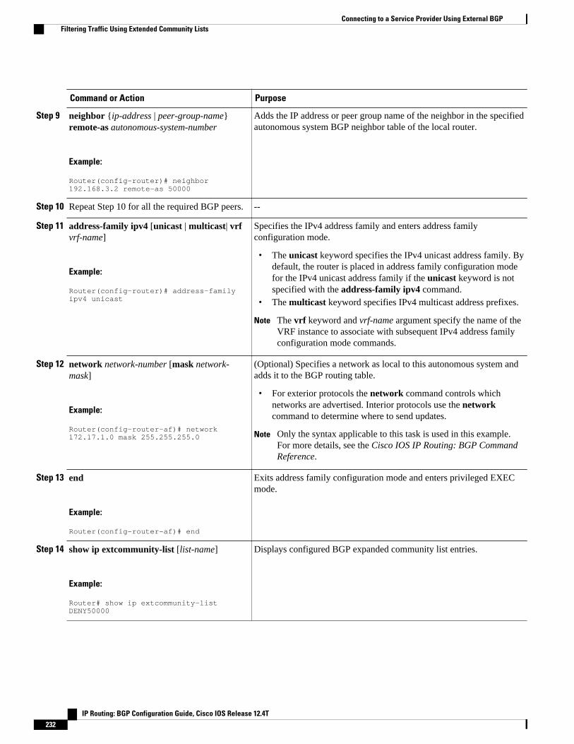
Command or Action Purpose
Step 9 neighbor {ip-address | peer-group-name}remote-as autonomous-system-number
Example:
Router(config-router)# neighbor 192.168.3.2 remote-as 50000
Adds the IP address or peer group name of the neighbor in the specifiedautonomous system BGP neighbor table of the local router.
Step 10 Repeat Step 10 for all the required BGP peers. --
Step 11 address-family ipv4 [unicast | multicast| vrfvrf-name]
Example:
Router(config-router)# address-family ipv4 unicast
Specifies the IPv4 address family and enters address familyconfiguration mode.
• The unicast keyword specifies the IPv4 unicast address family. Bydefault, the router is placed in address family configuration modefor the IPv4 unicast address family if the unicast keyword is notspecified with the address-family ipv4 command.
• The multicast keyword specifies IPv4 multicast address prefixes.
Note The vrf keyword and vrf-name argument specify the name of theVRF instance to associate with subsequent IPv4 address familyconfiguration mode commands.
Step 12 network network-number [mask network-mask]
Example:
Router(config-router-af)# network 172.17.1.0 mask 255.255.255.0
(Optional) Specifies a network as local to this autonomous system andadds it to the BGP routing table.
• For exterior protocols the network command controls whichnetworks are advertised. Interior protocols use the networkcommand to determine where to send updates.
Note Only the syntax applicable to this task is used in this example.For more details, see the Cisco IOS IP Routing: BGP CommandReference.
Step 13 end
Example:
Router(config-router-af)# end
Exits address family configuration mode and enters privileged EXECmode.
Step 14 show ip extcommunity-list [list-name]
Example:
Router# show ip extcommunity-list DENY50000
Displays configured BGP expanded community list entries.
Connecting to a Service Provider Using External BGP Filtering Traffic Using Extended Community Lists
IP Routing: BGP Configuration Guide, Cisco IOS Release 12.4T232

Examples
The following sample output verifies that the BGP expanded community list DENY50000 has beencreated, with the output showing that the entries to deny advertisements about autonomous system 50000have been resequenced from 10 and 20 to 50 and 150:
Router# show ip extcommunity-list DENY50000Expanded extended community-list DENY50000 50 deny _50000_ 150 deny ^50000 .*
Filtering Traffic Using a BGP Route Map Policy ListPerform this task to create a BGP policy list and then reference it within a route map.
A policy list is like a route map that contains only match clauses. With policy lists there are no changes tomatch clause semantics and route map functions. The match clauses are configured in policy lists withpermit and deny statements and the route map evaluates and processes each match clause to permit or denyroutes based on the configuration. AND and OR semantics in the route map function the same way forpolicy lists as they do for match clauses.
Policy lists simplify the configuration of BGP routing policy in medium-size and large networks. Thenetwork operator can reference preconfigured policy lists with groups of match clauses in route maps andeasily apply general changes to BGP routing policy. The network operator no longer needs to manuallyreconfigure each recurring group of match clauses that occur in multiple route map entries.
Perform this task to create a BGP policy list to filter traffic that matches the autonomous system path andMED of a router and then create a route map to reference the policy list.
BGP routing must be configured in your network and BGP neighbors must be established.
Note• BGP route map policy lists do not support the configuration of IP version 6 (IPv6) match clauses in
policy lists.• Policy lists are not supported in versions of Cisco IOS software prior to Cisco IOS Releases 12.0(22)S
and 12.2(15)T. Reloading a router that is running an older version of Cisco IOS software may causesome routing policy configurations to be lost.
• Policy lists support only match clauses and do not support set clauses. However, policy lists cancoexist, within the same route map entry, with match and set clauses that are configured separatelyfrom the policy lists.
• Policy lists are supported only by BGP. They are not supported by other IP routing protocols. Thislimitation does not interfere with normal operations of a route map, including redistribution, becausepolicy list functions operate transparently within BGP and are not visible to other IP routing protocols.
• Policy lists support only match clauses and do not support set clauses. However, policy lists cancoexist, within the same route map entry, with match and set clauses that are configured separatelyfrom the policy lists. The first route map example configures AND semantics, and the second routemap configuration example configures semantics. Both examples in this section show sample routemap configurations that reference policy lists and separate match and set clauses in the sameconfiguration.
Connecting to a Service Provider Using External BGPFiltering Traffic Using a BGP Route Map Policy List
IP Routing: BGP Configuration Guide, Cisco IOS Release 12.4T 233
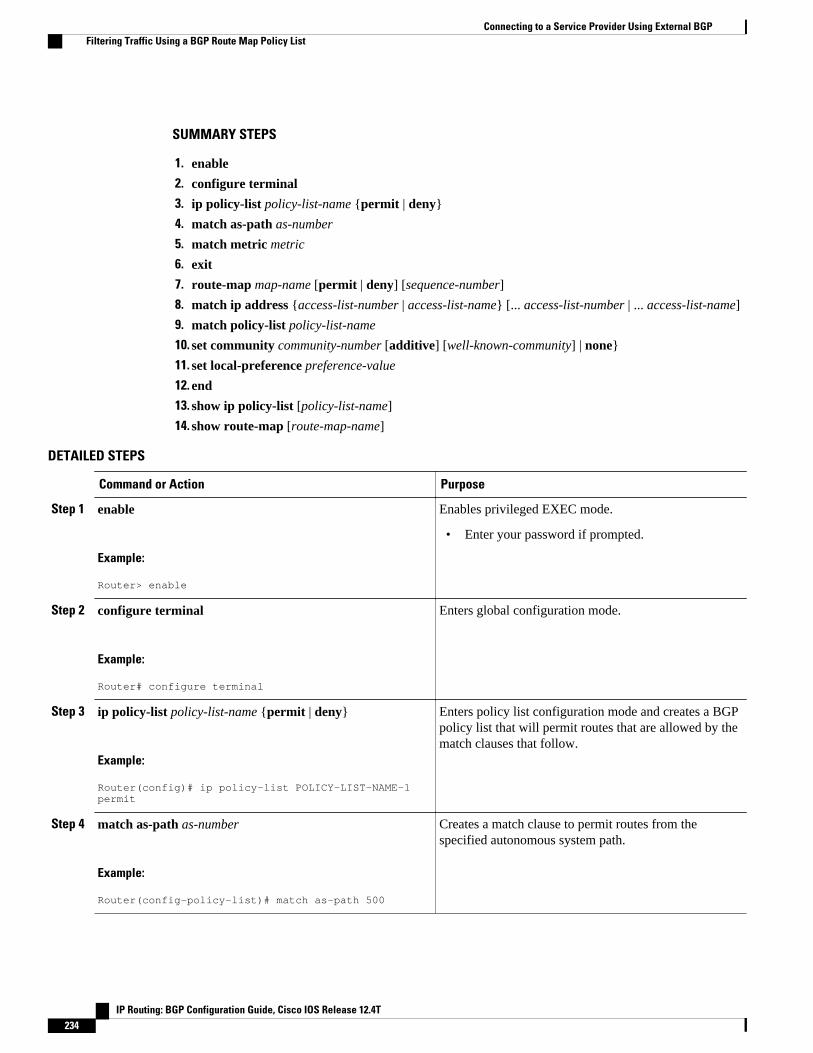
SUMMARY STEPS
1. enable
2. configure terminal
3. ip policy-list policy-list-name {permit | deny}
4. match as-path as-number
5. match metric metric
6. exit
7. route-map map-name [permit | deny] [sequence-number]
8. match ip address {access-list-number | access-list-name} [... access-list-number | ... access-list-name]
9. match policy-list policy-list-name
10. set community community-number [additive] [well-known-community] | none}
11. set local-preference preference-value
12. end
13. show ip policy-list [policy-list-name]
14. show route-map [route-map-name]
DETAILED STEPS
Command or Action Purpose
Step 1 enable
Example:
Router> enable
Enables privileged EXEC mode.
• Enter your password if prompted.
Step 2 configure terminal
Example:
Router# configure terminal
Enters global configuration mode.
Step 3 ip policy-list policy-list-name {permit | deny}
Example:
Router(config)# ip policy-list POLICY-LIST-NAME-1 permit
Enters policy list configuration mode and creates a BGPpolicy list that will permit routes that are allowed by thematch clauses that follow.
Step 4 match as-path as-number
Example:
Router(config-policy-list)# match as-path 500
Creates a match clause to permit routes from thespecified autonomous system path.
Connecting to a Service Provider Using External BGP Filtering Traffic Using a BGP Route Map Policy List
IP Routing: BGP Configuration Guide, Cisco IOS Release 12.4T234
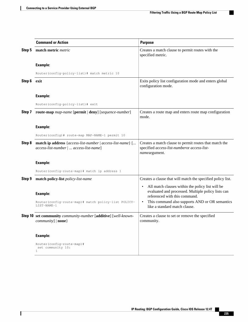
Command or Action Purpose
Step 5 match metric metric
Example:
Router(config-policy-list)# match metric 10
Creates a match clause to permit routes with thespecified metric.
Step 6 exit
Example:
Router(config-policy-list)# exit
Exits policy list configuration mode and enters globalconfiguration mode.
Step 7 route-map map-name [permit | deny] [sequence-number]
Example:
Router(config)# route-map MAP-NAME-1 permit 10
Creates a route map and enters route map configurationmode.
Step 8 match ip address {access-list-number | access-list-name} [...access-list-number | ... access-list-name]
Example:
Router(config-route-map)# match ip address 1
Creates a match clause to permit routes that match thespecified access-list-numberor access-list-nameargument.
Step 9 match policy-list policy-list-name
Example:
Router(config-route-map)# match policy-list POLICY-LIST-NAME-1
Creates a clause that will match the specified policy list.
• All match clauses within the policy list will beevaluated and processed. Multiple policy lists canreferenced with this command.
• This command also supports AND or OR semanticslike a standard match clause.
Step 10 set community community-number [additive] [well-known-community] | none}
Example:
Router(config-route-map)# set community 10:1
Creates a clause to set or remove the specifiedcommunity.
Connecting to a Service Provider Using External BGPFiltering Traffic Using a BGP Route Map Policy List
IP Routing: BGP Configuration Guide, Cisco IOS Release 12.4T 235
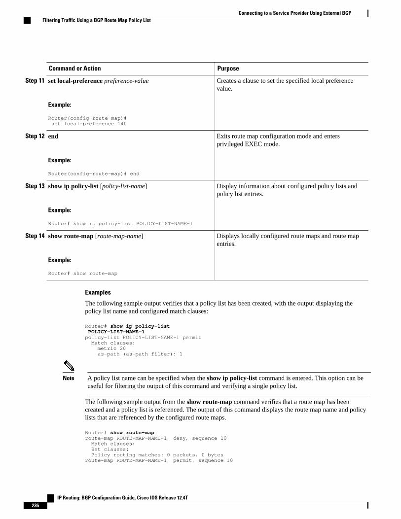
Command or Action Purpose
Step 11 set local-preference preference-value
Example:
Router(config-route-map)# set local-preference 140
Creates a clause to set the specified local preferencevalue.
Step 12 end
Example:
Router(config-route-map)# end
Exits route map configuration mode and entersprivileged EXEC mode.
Step 13 show ip policy-list [policy-list-name]
Example:
Router# show ip policy-list POLICY-LIST-NAME-1
Display information about configured policy lists andpolicy list entries.
Step 14 show route-map [route-map-name]
Example:
Router# show route-map
Displays locally configured route maps and route mapentries.
Examples
The following sample output verifies that a policy list has been created, with the output displaying thepolicy list name and configured match clauses:
Router# show ip policy-list POLICY-LIST-NAME-1policy-list POLICY-LIST-NAME-1 permit Match clauses: metric 20 as-path (as-path filter): 1
Note A policy list name can be specified when the show ip policy-list command is entered. This option can beuseful for filtering the output of this command and verifying a single policy list.
The following sample output from the show route-map command verifies that a route map has beencreated and a policy list is referenced. The output of this command displays the route map name and policylists that are referenced by the configured route maps.
Router# show route-maproute-map ROUTE-MAP-NAME-1, deny, sequence 10 Match clauses: Set clauses: Policy routing matches: 0 packets, 0 bytesroute-map ROUTE-MAP-NAME-1, permit, sequence 10
Connecting to a Service Provider Using External BGP Filtering Traffic Using a BGP Route Map Policy List
IP Routing: BGP Configuration Guide, Cisco IOS Release 12.4T236

Match clauses: IP Policy lists: POLICY-LIST-NAME-1 Set clauses: Policy routing matches: 0 packets, 0 bytes
Filtering Traffic Using Continue Clauses in a BGP Route MapPerform this task to filter traffic using continue clauses in a BGP route map.
SUMMARY STEPS
1. enable
2. configure terminal
3. router bgp autonomous-system-number
4. neighbor {ip-address| peer-group-name} remote-as autonomous-system-number
5. address-family ipv4 [unicast | multicast| vrf vrf-name]
6. neighbor {ip-address| peer-group-name} route-map map-name{in | out}
7. exit
8. exit
9. route-map map-name {permit | deny} [sequence-number]
10. match ip address {access-list-number | access-list-name} [... access-list-number | ... access-list-name]
11. set community community-number [additive] [well-known-community] | none}
12. continue [sequence-number]
13. end
14. show route-map [map-name]
DETAILED STEPS
Command or Action Purpose
Step 1 enable
Example:
Router> enable
Enables higher privilege levels, such as privileged EXEC mode.
• Enter your password if prompted.
Step 2 configure terminal
Example:
Router# configure terminal
Enters global configuration mode.
Step 3 router bgp autonomous-system-number
Example:
Router(config)# router bgp 50000
Enters router configuration mode, and creates a BGP routing process.
Connecting to a Service Provider Using External BGPFiltering Traffic Using Continue Clauses in a BGP Route Map
IP Routing: BGP Configuration Guide, Cisco IOS Release 12.4T 237

Command or Action Purpose
Step 4 neighbor {ip-address| peer-group-name}remote-as autonomous-system-number
Example:
Router(config-router)# neighbor 10.0.0.1 remote-as 50000
Adds the IP address or peer group name of the neighbor in the specifiedautonomous system to the IPv4 multiprotocol BGP neighbor table of thelocal router.
Step 5 address-family ipv4 [unicast | multicast|vrf vrf-name]
Example:
Router(config-router)# address-family ipv4 unicast
Specifies the IPv4 address family and enters address family configurationmode.
• The unicast keyword specifies the IPv4 unicast address family. Bydefault, the router is placed in address family configuration mode forthe IPv4 unicast address family if the unicast keyword is notspecified with the address-family ipv4 command.
• The multicast keyword specifies IPv4 multicast address prefixes.
The vrf keyword and vrf-name argument specify the name of the VRFinstance to associate with subsequent IPv4 address family configurationmode commands.
Step 6 neighbor {ip-address| peer-group-name}route-map map-name{in | out}
Example:
Router(config-router-af)# neighbor 10.0.0.1 route-map ROUTE-MAP-NAME in
Applies the inbound route map to routes received from the specifiedneighbor, or applies an outbound route map to routes advertised to thespecified neighbor.
Step 7 exit
Example:
Router(config-router-af)# exit
Exits address family configuration mode and enters router configurationmode.
Step 8 exit
Example:
Router(config-router)# exit
Exits router configuration mode and enters global configuration mode.
Step 9 route-map map-name {permit | deny}[sequence-number]
Example:
Router(config)# route-map ROUTE-MAP-NAME permit 10
Enters route-map configuration mode to create or configure a route map.
Connecting to a Service Provider Using External BGP Filtering Traffic Using Continue Clauses in a BGP Route Map
IP Routing: BGP Configuration Guide, Cisco IOS Release 12.4T238

Command or Action Purpose
Step 10 match ip address {access-list-number |access-list-name} [... access-list-number | ...access-list-name]
Example:
Router(config-route-map)# match ip address 1
Configures a match command that specifies the conditions under whichpolicy routing and route filtering occur.
• Multiple match commands can be configured. If a match commandis configured, a match must occur in order for the continue statementto be executed. If a match command is not configured, set andcontinue clauses will be executed.
Note The match and set commands used in this task are examples thatare used to help describe the operation of the continue command.For a list of specific match and set commands, see the continuecommand in the Cisco IOS IP Routing: BGP Command Reference.
Step 11 set community community-number[additive] [well-known-community] | none}
Example:
Router(config-route-map)# set community 10:1
Configures a set command that specifies the routing action to perform ifthe criteria enforced by the match commands are met.
• Multiple set commands can be configured.• In this example, a clause is created to set the specified community.
Step 12 continue [sequence-number]
Example:
Router(config-route-map)# continue
Configures a route map to continue to evaluate and execute matchstatements after a successful match occurs.
• If a sequence number is configured, the continue clause will go to theroute map with the specified sequence number.
• If no sequence number is specified, the continue clause will go to theroute map with the next sequence number. This behavior is called an"implied continue."
Note Continue clauses in outbound route maps are supported only inCisco IOS Release 12.0(31)S, 12.2(33)SB, 12.2(33)SRB,12.2(33)SXI, 12.4(4)T, and later releases.
Step 13 end
Example:
Router(config-route-map)# end
Exits route-map configuration mode and enters privileged EXEC mode.
Step 14 show route-map [map-name]
Example:
Router# show route-map
(Optional) Displays locally configured route maps. The name of the routemap can be specified in the syntax of this command to filter the output.
Connecting to a Service Provider Using External BGPFiltering Traffic Using Continue Clauses in a BGP Route Map
IP Routing: BGP Configuration Guide, Cisco IOS Release 12.4T 239

Examples
The following sample output shows how to verify the configuration of continue clauses using the showroute-map command. The output displays configured route maps including the match, set, and continueclauses.
Router# show route-maproute-map MARKETING, permit, sequence 10 Match clauses: ip address (access-lists): 1 metric 10 Continue: sequence 40 Set clauses: as-path prepend 10 Policy routing matches: 0 packets, 0 bytesroute-map MARKETING, permit, sequence 20 Match clauses: ip address (access-lists): 2 metric 20 Set clauses: as-path prepend 10 10 Policy routing matches: 0 packets, 0 bytesroute-map MARKETING, permit, sequence 30 Match clauses: Continue: to next entry 40 Set clauses: as-path prepend 10 10 10 Policy routing matches: 0 packets, 0 bytesroute-map MARKETING, permit, sequence 40 Match clauses: community (community-list filter): 10:1 Set clauses: local-preference 104 Policy routing matches: 0 packets, 0 bytesroute-map MKTG-POLICY-MAP, permit, sequence 10 Match clauses: Set clauses: community 655370 Policy routing matches: 0 packets, 0 bytes
Configuration Examples for Connecting to a Service ProviderUsing External BGP
• Influencing Inbound Path Selection Examples, page 241
• Influencing Inbound Path Selection by Modifying the AS-path Attribute Using 4-Byte AS NumbersExample, page 241
• Influencing Outbound Path Selection Examples, page 243
• Filtering BGP Prefixes with Prefix Lists Examples, page 244
• Filtering Traffic Using Community Lists Examples, page 245
• Filtering Traffic Using AS-path Filters Example, page 246
• Filtering Traffic with AS-path Filters Using 4-Byte Autonomous System Numbers Examples, page246
• Filtering Traffic Using Extended Community Lists with 4-Byte Autonomous System NumbersExample, page 247
• Filtering Traffic Using a BGP Route Map Example, page 250
• Filtering Traffic Using Continue Clauses in a BGP Route Map Examples, page 250
Connecting to a Service Provider Using External BGP Configuration Examples for Connecting to a Service Provider Using External BGP
IP Routing: BGP Configuration Guide, Cisco IOS Release 12.4T240

Influencing Inbound Path Selection ExamplesThe following example shows how you can use route maps to modify incoming data from a neighbor. Anyroute received from 10.222.1.1 that matches the filter parameters set in autonomous system access list 200will have its weight set to 200 and its local preference set to 250, and it will be accepted.
router bgp 100! neighbor 10.222.1.1 route-map FIX-WEIGHT in neighbor 10.222.1.1 remote-as 1!ip as-path access-list 200 permit ^690$ip as-path access-list 200 permit ^1800!route-map FIX-WEIGHT permit 10 match as-path 200 set local-preference 250 set weight 200
In the following example, the route map named finance marks all paths originating from autonomoussystem 690 with an MED metric attribute of 127. The second permit clause is required so that routes notmatching autonomous system path list 1 will still be sent to neighbor 10.1.1.1.
router bgp 65000 neighbor 10.1.1.1 route-map finance out!ip as-path access-list 1 permit ^690_ip as-path access-list 2 permit .*!route-map finance permit 10 match as-path 1 set metric 127!route-map finance permit 20 match as-path 2
Inbound route maps could perform prefix-based matching and set various parameters of the update.Inbound prefix matching is available in addition to autonomous system path and community list matching.The following example shows how the set local-preference route map configuration command sets thelocal preference of the inbound prefix 172.20.0.0/16 to 120:
!router bgp 65100 network 10.108.0.0 neighbor 10.108.1.1 remote-as 65200 neighbor 10.108.1.1 route-map set-local-pref in !route-map set-local-pref permit 10 match ip address 2 set local preference 120!route-map set-local-pref permit 20!access-list 2 permit 172.20.0.0 0.0.255.255access-list 2 deny any
Influencing Inbound Path Selection by Modifying the AS-path AttributeUsing 4-Byte AS Numbers Example
This example shows how to configure BGP to influence the inbound path selection for traffic destined forthe 172.17.1.0 network by modifying the AS-path attribute. In Cisco IOS Release 12.0(32)SY8,12.0(33)S3, 12.2(33)SXI1, and later releases, BGP support for 4-octet (4-byte) autonomous system
Influencing Inbound Path Selection ExamplesConfiguration Examples for Connecting to a Service Provider Using External BGP
IP Routing: BGP Configuration Guide, Cisco IOS Release 12.4T 241
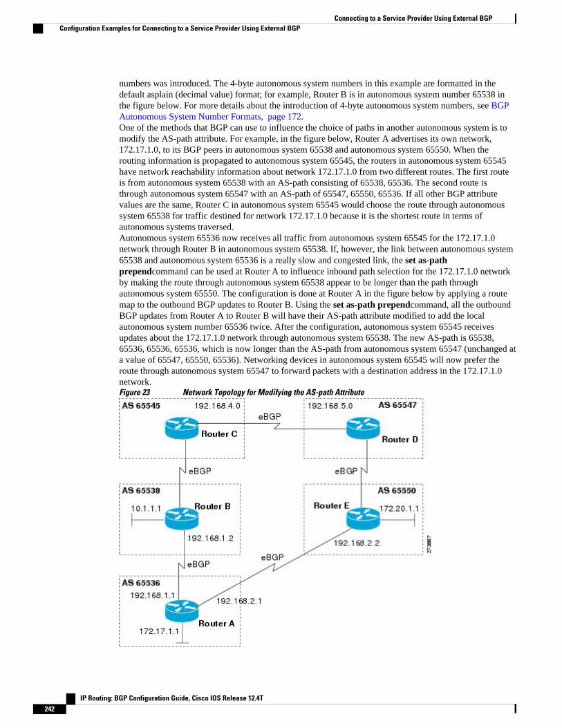
numbers was introduced. The 4-byte autonomous system numbers in this example are formatted in thedefault asplain (decimal value) format; for example, Router B is in autonomous system number 65538 inthe figure below. For more details about the introduction of 4-byte autonomous system numbers, see BGPAutonomous System Number Formats, page 172.One of the methods that BGP can use to influence the choice of paths in another autonomous system is tomodify the AS-path attribute. For example, in the figure below, Router A advertises its own network,172.17.1.0, to its BGP peers in autonomous system 65538 and autonomous system 65550. When therouting information is propagated to autonomous system 65545, the routers in autonomous system 65545have network reachability information about network 172.17.1.0 from two different routes. The first routeis from autonomous system 65538 with an AS-path consisting of 65538, 65536. The second route isthrough autonomous system 65547 with an AS-path of 65547, 65550, 65536. If all other BGP attributevalues are the same, Router C in autonomous system 65545 would choose the route through autonomoussystem 65538 for traffic destined for network 172.17.1.0 because it is the shortest route in terms ofautonomous systems traversed.Autonomous system 65536 now receives all traffic from autonomous system 65545 for the 172.17.1.0network through Router B in autonomous system 65538. If, however, the link between autonomous system65538 and autonomous system 65536 is a really slow and congested link, the set as-pathprependcommand can be used at Router A to influence inbound path selection for the 172.17.1.0 networkby making the route through autonomous system 65538 appear to be longer than the path throughautonomous system 65550. The configuration is done at Router A in the figure below by applying a routemap to the outbound BGP updates to Router B. Using the set as-path prependcommand, all the outboundBGP updates from Router A to Router B will have their AS-path attribute modified to add the localautonomous system number 65536 twice. After the configuration, autonomous system 65545 receivesupdates about the 172.17.1.0 network through autonomous system 65538. The new AS-path is 65538,65536, 65536, 65536, which is now longer than the AS-path from autonomous system 65547 (unchanged ata value of 65547, 65550, 65536). Networking devices in autonomous system 65545 will now prefer theroute through autonomous system 65547 to forward packets with a destination address in the 172.17.1.0network.Figure 23 Network Topology for Modifying the AS-path Attribute
Connecting to a Service Provider Using External BGP Configuration Examples for Connecting to a Service Provider Using External BGP
IP Routing: BGP Configuration Guide, Cisco IOS Release 12.4T242
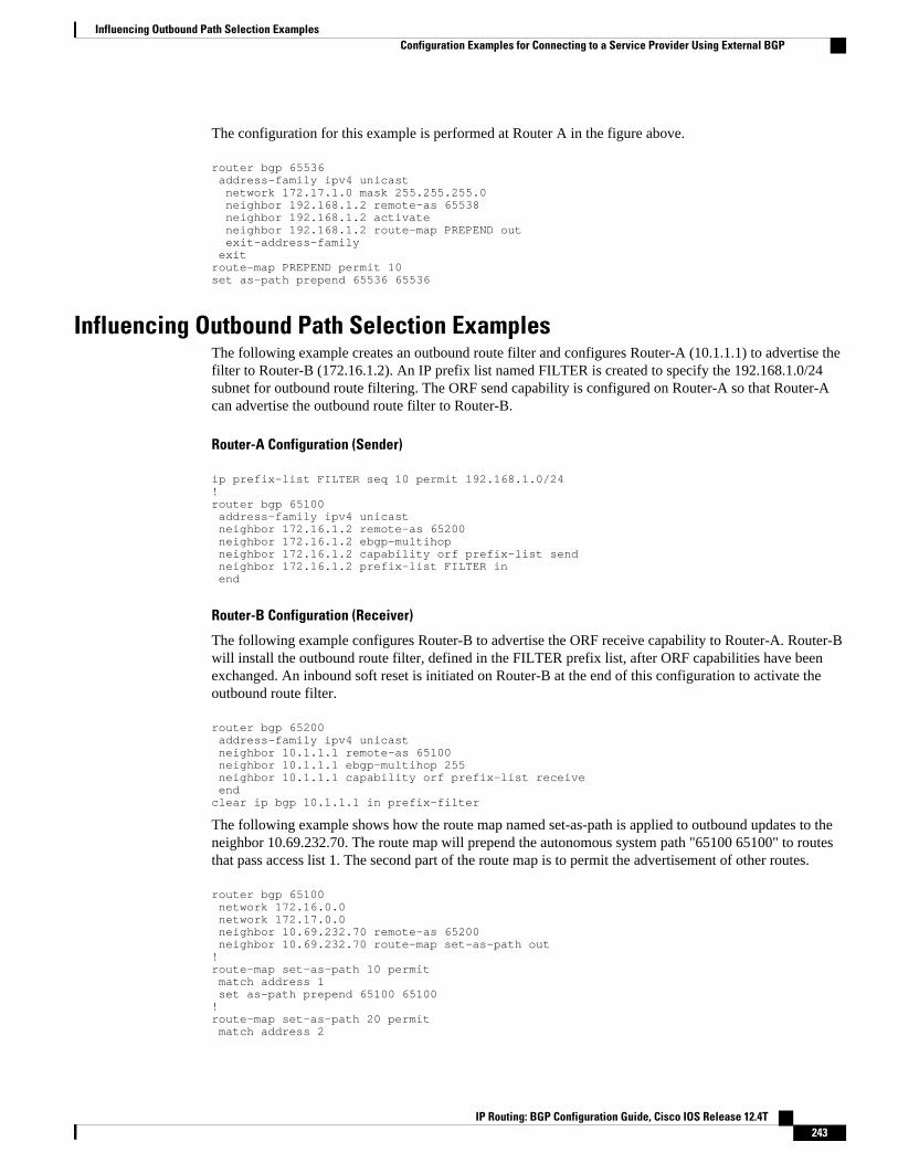
The configuration for this example is performed at Router A in the figure above.
router bgp 65536 address-family ipv4 unicast network 172.17.1.0 mask 255.255.255.0 neighbor 192.168.1.2 remote-as 65538 neighbor 192.168.1.2 activate neighbor 192.168.1.2 route-map PREPEND out exit-address-family exitroute-map PREPEND permit 10set as-path prepend 65536 65536
Influencing Outbound Path Selection ExamplesThe following example creates an outbound route filter and configures Router-A (10.1.1.1) to advertise thefilter to Router-B (172.16.1.2). An IP prefix list named FILTER is created to specify the 192.168.1.0/24subnet for outbound route filtering. The ORF send capability is configured on Router-A so that Router-Acan advertise the outbound route filter to Router-B.
Router-A Configuration (Sender)
ip prefix-list FILTER seq 10 permit 192.168.1.0/24 !router bgp 65100 address-family ipv4 unicast neighbor 172.16.1.2 remote-as 65200 neighbor 172.16.1.2 ebgp-multihop neighbor 172.16.1.2 capability orf prefix-list send neighbor 172.16.1.2 prefix-list FILTER in end
Router-B Configuration (Receiver)
The following example configures Router-B to advertise the ORF receive capability to Router-A. Router-Bwill install the outbound route filter, defined in the FILTER prefix list, after ORF capabilities have beenexchanged. An inbound soft reset is initiated on Router-B at the end of this configuration to activate theoutbound route filter.
router bgp 65200 address-family ipv4 unicast neighbor 10.1.1.1 remote-as 65100 neighbor 10.1.1.1 ebgp-multihop 255 neighbor 10.1.1.1 capability orf prefix-list receive end clear ip bgp 10.1.1.1 in prefix-filter
The following example shows how the route map named set-as-path is applied to outbound updates to theneighbor 10.69.232.70. The route map will prepend the autonomous system path "65100 65100" to routesthat pass access list 1. The second part of the route map is to permit the advertisement of other routes.
router bgp 65100 network 172.16.0.0 network 172.17.0.0 neighbor 10.69.232.70 remote-as 65200 neighbor 10.69.232.70 route-map set-as-path out!route-map set-as-path 10 permit match address 1 set as-path prepend 65100 65100!route-map set-as-path 20 permit match address 2
Influencing Outbound Path Selection ExamplesConfiguration Examples for Connecting to a Service Provider Using External BGP
IP Routing: BGP Configuration Guide, Cisco IOS Release 12.4T 243
!access-list 1 permit 172.16.0.0 0.0.255.255access-list 1 permit 172.17.0.0 0.0.255.255!access-list 2 permit 0.0.0.0 255.255.255.255
Filtering BGP Prefixes with Prefix Lists ExamplesThis section contains the following examples:
• Filtering BGP Prefixes Using a Single Prefix List, page 244
• Filtering BGP Prefixes Using a Group of Prefixes, page 245
• Adding or Deleting Prefix List Entries, page 245
Filtering BGP Prefixes Using a Single Prefix ListThe following example shows how a prefix list denies the default route 0.0.0.0/0:
ip prefix-list abc deny 0.0.0.0/0
The following example shows how a prefix list permits a route that matches the prefix 10.0.0.0/8:
ip prefix-list abc permit 10.0.0.0/8
The following example shows how to configure the BGP process so that it accepts only prefixes with aprefix length of /8 to /24:
router bgp 40000 network 10.20.20.0 distribute-list prefix max24 in!ip prefix-list max24 seq 5 permit 0.0.0.0/0 ge 8 le 24
The following example configuration shows how to conditionally originate a default route (0.0.0.0/0) inRIP when a prefix 10.1.1.0/24 exists in the routing table:
ip prefix-list cond permit 10.1.1.0/24!route-map default-condition permit 10 match ip address prefix-list cond!router rip default-information originate route-map default-condition
The following example shows how to configure BGP to accept routing updates from 192.168.1.1 only,besides filtering on the prefix length:
router bgp 40000 distribute-list prefix max24 gateway allowlist in !ip prefix-list allowlist seq 5 permit 192.168.1.1/32 !
The following example shows how to direct the BGP process to filter incoming updates to the prefix usingname1, and match the gateway (next hop) of the prefix being updated to the prefix list name2, onGigabitEthernet interface 0/0/0:
router bgp 103 distribute-list prefix name1 gateway name2 in gigabitethernet 0/0/0
Filtering BGP Prefixes with Prefix Lists Examples Filtering BGP Prefixes Using a Single Prefix List
IP Routing: BGP Configuration Guide, Cisco IOS Release 12.4T244

Filtering BGP Prefixes Using a Group of PrefixesThe following example shows how to configure BGP to permit routes with a prefix length up to 24 innetwork 192/8:
ip prefix-list abc permit 192.0.0.0/8 le 24
The following example shows how to configure BGP to deny routes with a prefix length greater than 25 in192/8:
ip prefix-list abc deny 192.0.0.0/8 ge 25
The following example shows how to configure BGP to permit routes with a prefix length greater than 8and less than 24 in all address space:
ip prefix-list abc permit 0.0.0.0/0 ge 8 le 24
The following example shows how to configure BGP to deny routes with a prefix length greater than 25 inall address space:
ip prefix-list abc deny 0.0.0.0/0 ge 25
The following example shows how to configure BGP to deny all routes in network 10/8, because any routein the Class A network 10.0.0.0/8 is denied if its mask is less than or equal to 32 bits:
ip prefix-list abc deny 10.0.0.0/8 le 32
The following example shows how to configure BGP to deny routes with a mask greater than 25 in192.168.1.0/24:
ip prefix-list abc deny 192.168.1.0/24 ge 25
The following example shows how to configure BGP to permit all routes:
ip prefix-list abc permit 0.0.0.0/0 le 32
Adding or Deleting Prefix List EntriesYou can add or delete individual entries in a prefix list if a prefix list has the following initial configuration:
ip prefix-list abc deny 0.0.0.0/0 le 7ip prefix-list abc deny 0.0.0.0/0 ge 25ip prefix-list abc permit 192.168.0.0/15
The following example shows how to delete an entry from the prefix list so that 192.168.0.0 is notpermitted, and add a new entry that permits 10.0.0.0/8:
no ip prefix-list abc permit 192.168.0.0/15 ip prefix-list abc permit 10.0.0.0/8
The new configuration is as follows:
ip prefix-list abc deny 0.0.0.0/0 le 7ip prefix-list abc deny 0.0.0.0/0 ge 25ip prefix-list abc permit 10.0.0.0/8
Filtering Traffic Using Community Lists ExamplesThis section contains two examples of the use of BGP communities with route maps.
Filtering Traffic Using Community Lists ExamplesFiltering BGP Prefixes Using a Group of Prefixes
IP Routing: BGP Configuration Guide, Cisco IOS Release 12.4T 245

The first example shows how the route map named set-community is applied to the outbound updates to theneighbor 172.16.232.50. The routes that pass access list 1 have the special community attribute value no-export. The remaining routes are advertised normally. This special community value automatically preventsthe advertisement of those routes by the BGP speakers in autonomous system 200.
router bgp 100 neighbor 172.16.232.50 remote-as 200 neighbor 172.16.232.50 send-community neighbor 172.16.232.50 route-map set-community out!route-map set-community permit 10 match address 1 set community no-export!route-map set-community permit 20 match address 2
The second example shows how the route map named set-community is applied to the outbound updates toneighbor 172.16.232.90. All the routes that originate from autonomous system 70 have the communityvalues 200 200 added to their already existing values. All other routes are advertised as normal.
route-map bgp 200 neighbor 172.16.232.90 remote-as 100 neighbor 172.16.232.90 send-community neighbor 172.16.232.90 route-map set-community out!route-map set-community permit 10 match as-path 1 set community 200 200 additive!route-map set-community permit 20!ip as-path access-list 1 permit 70$ip as-path access-list 2 permit .*
Filtering Traffic Using AS-path Filters ExampleThe following example shows BGP path filtering by neighbor. Only the routes that pass autonomoussystem path access list 2 will be sent to 192.168.12.10. Similarly, only routes passing access list 3 will beaccepted from 192.168.12.10.
router bgp 200 neighbor 192.168.12.10 remote-as 100 neighbor 192.168.12.10 filter-list 1 out neighbor 192.168.12.10 filter-list 2 in exitip as-path access-list 1 permit _109_ip as-path access-list 2 permit _200$ip as-path access-list 2 permit ^100$ip as-path access-list 3 deny _690$ip as-path access-list 3 permit .*
Filtering Traffic with AS-path Filters Using 4-Byte Autonomous SystemNumbers Examples
Asplain Default Format in Cisco IOS Release 12.0(32)SY8, 12.0(33)S3, 12.2(33)SRE, 12.2(33)SXI1, and LaterReleases
The following example is available in Cisco IOS Release 12.0(32)SY8, 12.0(33)S3, 12.2(33)SRE,12.2(33)XNE, 12.2(33)SXI1, and later releases and shows BGP path filtering by neighbor using 4-byte
Filtering Traffic Using AS-path Filters Example Adding or Deleting Prefix List Entries
IP Routing: BGP Configuration Guide, Cisco IOS Release 12.4T246
autonomous system numbers in asplain format. Only the routes that pass autonomous system path accesslist 2 will be sent to 192.168.3.2.
ip as-path access-list 2 permit ^65536$router bgp 65538 address-family ipv4 unicast neighbor 192.168.3.2 remote-as 65550 neighbor 192.168.3.2 activate neighbor 192.168.3.2 filter-list 2 in end
Asdot Default Format in Cisco IOS Release 12.0(32)S12, and 12.4(24)T
The following example available in Cisco IOS Release 12.0(32)S12, 12.4(24)T, and later releases showsBGP path filtering by neighbor using 4-byte autonomous system numbers in asdot format. Only the routesthat pass autonomous system path access list 2 will be sent to 192.168.3.2.
Note In Cisco IOS Release 12.0(32)SY8, 12.0(33)S3, 12.2(33)SRE, 12.2(33)XNE, 12.2(33)SXI1, and laterreleases, this example works if you have configured asdot as the default display format using the bgpasnotation dot command.
ip as-path access-list 2 permit ^1\.0$router bgp 1.2 address-family ipv4 unicast neighbor 192.168.3.2 remote-as 1.14 neighbor 192.168.3.2 filter-list 2 in end
Filtering Traffic Using Extended Community Lists with 4-Byte AutonomousSystem Numbers Example
Asplain Default Format in Cisco IOS Release 12.0(32)SY8, 12.0(33)S3, 12.2(33)SRE, 12.2(33)SXI1, and LaterReleases
The following example shows how to filter traffic by creating an extended BGP community list to controloutbound routes. In Cisco IOS Release 12.0(32)SY8, 12.0(33)S3, 12.2(33)SRE, 12.2(33)XNE,12.2(33)SXI1, and later releases, extended BGP communities support 4-byte autonomous system numbersin the regular expressions in asplain by default. Extended community attributes are used to configure, filter,and identify routes for VRF instances and MPLS VPNs. The ip extcommunity-listcommand is used toconfigure named or numbered extended community lists. All of the standard rules of access lists apply to
Filtering Traffic Using Extended Community Lists with 4-Byte Autonomous System Numbers ExampleAdding or Deleting Prefix List Entries
IP Routing: BGP Configuration Guide, Cisco IOS Release 12.4T 247
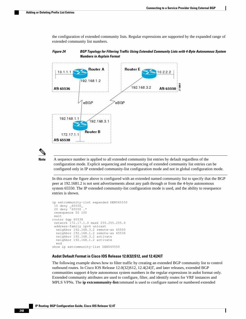
the configuration of extended community lists. Regular expressions are supported by the expanded range ofextended community list numbers.
Figure 24 BGP Topology for Filtering Traffic Using Extended Community Lists with 4-Byte Autonomous SystemNumbers in Asplain Format
Note A sequence number is applied to all extended community list entries by default regardless of theconfiguration mode. Explicit sequencing and resequencing of extended community list entries can beconfigured only in IP extended community-list configuration mode and not in global configuration mode.
In this exam the figure above is configured with an extended named community list to specify that the BGPpeer at 192.1681.2 is not sent advertisements about any path through or from the 4-byte autonomoussystem 65550. The IP extended community-list configuration mode is used, and the ability to resequenceentries is shown.
ip extcommunity-list expanded DENY65550 10 deny _65550_ 20 deny ^65550 .* resequence 50 100 exitrouter bgp 65538 network 172.17.1.0 mask 255.255.255.0 address-family ipv4 unicast neighbor 192.168.3.2 remote-as 65550 neighbor 192.168.1.2 remote-as 65536 neighbor 192.168.3.2 activate neighbor 192.168.1.2 activate endshow ip extcommunity-list DENY65550
Asdot Default Format in Cisco IOS Release 12.0(32)S12, and 12.4(24)T
The following example shows how to filter traffic by creating an extended BGP community list to controloutbound routes. In Cisco IOS Release 12.0(32)S12, 12.4(24)T, and later releases, extended BGPcommunities support 4-byte autonomous system numbers in the regular expressions in asdot format only.Extended community attributes are used to configure, filter, and identify routes for VRF instances andMPLS VPNs. The ip extcommunity-listcommand is used to configure named or numbered extended
Connecting to a Service Provider Using External BGP Adding or Deleting Prefix List Entries
IP Routing: BGP Configuration Guide, Cisco IOS Release 12.4T248

community lists. All of the standard rules of access lists apply to the configuration of extended communitylists. Regular expressions are supported by the expanded range of extended community list numbers.
Note In Cisco IOS Release 12.0(32)SY8, 12.0(33)S3, 12.2(33)SXI1, and later releases, this example works ifyou have configured asdot as the default display format using the bgp asnotation dot command.
Figure 25 BGP Topology for Filtering Traffic Using Extended Community Lists with 4-Byte Autonomous SystemNumbers in Asdot Format
Note A sequence number is applied to all extended community list entries by default regardless of theconfiguration mode. Explicit sequencing and resequencing of extended community list entries can beconfigured only in IP extended community-list configuration mode and not in global configuration mode.
In this exam the figure above is configured with an extended named community list to specify that the BGPpeer at 192.1681.2 is not sent advertisements about any path through or from the 4-byte autonomoussystem 65550. The IP extended community-list configuration mode is used, and the ability to resequenceentries is shown.
ip extcommunity-list expanded DENY114 10 deny _1\.14_ 20 deny ^1\.14 .* resequence 50 100 exitrouter bgp 1.2 network 172.17.1.0 mask 255.255.255.0 address-family ipv4 unicast neighbor 192.168.3.2 remote-as 1.14 neighbor 192.168.1.2 remote-as 1.0 neighbor 192.168.3.2 activate neighbor 192.168.1.2 activate endshow ip extcommunity-list DENY114
Connecting to a Service Provider Using External BGPAdding or Deleting Prefix List Entries
IP Routing: BGP Configuration Guide, Cisco IOS Release 12.4T 249

Filtering Traffic Using a BGP Route Map ExampleThe following example shows how to use an address family to configure BGP so that any unicast andmulticast routes from neighbor 10.1.1.1 are accepted if they match access list 1:
route-map filter-some-multicast match ip address 1 exitrouter bgp 65538 neighbor 10.1.1.1 remote-as 65537 address-family ipv4 unicast neighbor 10.1.1.1 activate neighbor 10.1.1.1 route-map filter-some-multicast in exit exitrouter bgp 65538 neighbor 10.1.1.1 remote-as 65537 address-family ipv4 multicast neighbor 10.1.1.1 activate neighbor 10.1.1.1 route-map filter-some-multicast in end
Filtering Traffic Using Continue Clauses in a BGP Route Map ExamplesThe following example shows continue clause configuration in a route map sequence.
Note Continue clauses in outbound route maps are supported only in Cisco IOS Release 12.0(31)S, 12.2(33)SB,12.2(33)SRB, 12.2(33)SXI, 12.4(4)T, and later releases.
The first continue clause in route map entry 10 indicates that the route map will go to route map entry 30 ifa successful matches occurs. If a match does not occur, the route map will "fall through" to route map entry20. If a successful match occurs in route map entry 20, the set action will be executed and the route mapwill not evaluate any additional route map entries. Only the first successful match ip address clause issupported.
If a successful match does not occur in route map entry 20, the route map will "fall through" to route mapentry 30. This sequence does not contain a match clause, so the set clause will be automatically executedand the continue clause will go to the next route map entry because a sequence number is not specified.
If there are no successful matches, the route map will "fall through" to route map entry 30 and execute theset clause. A sequence number is not specified for the continue clause so route map entry 40 will beevaluated.
There are two behaviors that can occur when the same set command is repeated in subsequent continueclause entries. For set commands that configure an additive or accumulative value (for example, setcommunity additive, set extended community additive, and set as-path prepend), subsequent values areadded by subsequent entries. The following example illustrates this behavior. After each set of matchclauses, a set as-path prepend command is configured to add an autonomous system number to the as-path. After a match occurs, the route map stops evaluating match clauses and starts executing the setclauses, in the order in which they were configured. Depending on how many successful match clausesoccur, the as-path is prepended by one, two, or three autonomous system numbers.
route-map ROUTE-MAP-NAME permit 10 match ip address 1 match metric 10 set as-path prepend 10 continue 30 !
Filtering Traffic Using a BGP Route Map Example Adding or Deleting Prefix List Entries
IP Routing: BGP Configuration Guide, Cisco IOS Release 12.4T250

route-map ROUTE-MAP-NAME permit 20 match ip address 2 match metric 20 set as-path prepend 10 10 !route-map ROUTE-MAP-NAME permit 30 set as-path prepend 10 10 10 continue !route-map ROUTE-MAP-NAME permit 40 match community 10:1 set local-preference 104
In this example, the same set command is repeated in subsequent continue clause entries but the behavior isdifferent from the first example. For setcommands that configure an absolute value, the value from the lastinstance will overwrite the previous value(s). The following example illustrates this behavior. The setclause value in sequence 20 overwrites the set clause value from sequence 10. The next hop for prefixesfrom the 172.16/16 network is set to 10.2.2.2 and not 10.1.1.1.
ip prefix-list 1 permit 172.16.0.0/16 ip prefix-list 2 permit 192.168.1.0/24 route-map RED permit 10 match ip address prefix-list 1 set ip next hop 10.1.1.1 continue 20 exit route-map RED permit 20 match ip address prefix-list 2 set ip next hop 10.2.2.2 end
Note Route maps have a linear behavior and not a nested behavior. Once a route is matched in a route mappermit entry with a continue command clause, it will not be processed by the implicit deny at the end of theroute-map. The following example illustrates this case.
In the following example, when routes match an as-path of 10, 20, or 30, the routes are permitted and thecontinue clause jumps over the explicit deny clause to process the match ip address prefix list. If a matchoccurs here, the route metric is set to 100. Only routes that do not match an as-path of 10, 20, or 30 and domatch a community number of 30 are denied. To deny other routes, you must configure an explicit denystatement.
route-map test permit 10 match as-path 10 20 30 continue 30 exitroute-map test deny 20 match community 30 exitroute-map test permit 30 match ip address prefix-list 1 set metric 100 exit
Where to Go Next• To configure advanced BGP feature tasks, proceed to the "Configuring Advanced BGP Features"
module.• To configure BGP neighbor session options, proceed to the "Configuring BGP Neighbor Session
Options" module.
Connecting to a Service Provider Using External BGPWhere to Go Next
IP Routing: BGP Configuration Guide, Cisco IOS Release 12.4T 251

• To configure internal BGP tasks, proceed to the "Configuring Internal BGP Features" module.
Additional ReferencesThe following sections provide references related to connecting to a service provider using external BGP.
Related Documents
Related Topic Document Title
Cisco IOS commands Cisco IOS Master Commands List, All Releases
BGP commands: complete command syntax,command mode, defaults, command history, usageguidelines, and examples
Cisco IOS IP Routing: BGP Command Reference
BGP overview "Cisco BGP Overview" module
Configuring basic BGP tasks "Configuring a Basic BGP Network" module
BGP fundamentals and description Large-Scale IP Network Solutions , Khalid Razaand Mark Turner, Cisco Press, 2000
Implementing and controlling BGP in scalablenetworks
Building Scalable Cisco Networks , CatherinePaquet and Diane Teare, Cisco Press, 2001
Interdomain routing basics Internet Routing Architectures , Bassam Halabi,Cisco Press, 1997
Standards
Standard Title
MDT SAFI MDT SAFI
MIBs
MIB MIBs Link
CISCO-BGP4-MIB To locate and download MIBs for selectedplatforms, Cisco IOS releases, and feature sets, useCisco MIB Locator found at the following URL:
http://www.cisco.com/go/mibs
RFCs
RFC Title
RFC 1772 Application of the Border Gateway Protocol in theInternet
Connecting to a Service Provider Using External BGP Additional References
IP Routing: BGP Configuration Guide, Cisco IOS Release 12.4T252

RFC Title
RFC 1773 Experience with the BGP Protocol
RFC 1774 BGP-4 Protocol Analysis
RFC 1930 Guidelines for Creation, Selection, andRegistration of an Autonomous System (AS)
RFC 2519 A Framework for Inter-Domain Route Aggregation
RFC 2858 Multiprotocol Extensions for BGP-4
RFC 2918 Route Refresh Capability for BGP-4
RFC 3392 Capabilities Advertisement with BGP-4
RFC 4271 A Border Gateway Protocol 4 (BGP-4)
RFC 4893 BGP Support for Four-Octet AS Number Space
RFC 5396 Textual Representation of Autonomous system(AS) Numbers
RFC 5398 Autonomous System (AS) Number Reservation forDocumentation Use
Technical Assistance.
Description Link
The Cisco Support website provides extensiveonline resources, including documentation and toolsfor troubleshooting and resolving technical issueswith Cisco products and technologies.
To receive security and technical information aboutyour products, you can subscribe to variousservices, such as the Product Alert Tool (accessedfrom Field Notices), the Cisco Technical ServicesNewsletter, and Really Simple Syndication (RSS)Feeds.
Access to most tools on the Cisco Support websiterequires a Cisco.com user ID and password.
http://www.cisco.com/cisco/web/support/index.html
Feature Information for Connecting to a Service ProviderUsing External BGP
The following table provides release information about the feature or features described in this module.This table lists only the software release that introduced support for a given feature in a given software
Connecting to a Service Provider Using External BGPFeature Information for Connecting to a Service Provider Using External BGP
IP Routing: BGP Configuration Guide, Cisco IOS Release 12.4T 253
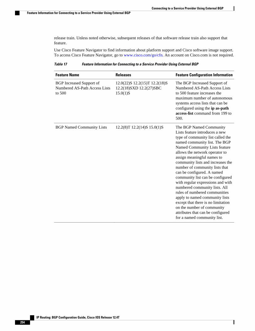
release train. Unless noted otherwise, subsequent releases of that software release train also support thatfeature.
Use Cisco Feature Navigator to find information about platform support and Cisco software image support.To access Cisco Feature Navigator, go to www.cisco.com/go/cfn. An account on Cisco.com is not required.
Table 17 Feature Information for Connecting to a Service Provider Using External BGP
Feature Name Releases Feature Configuration Information
BGP Increased Support ofNumbered AS-Path Access Liststo 500
12.0(22)S 12.2(15)T 12.2(18)S12.2(18)SXD 12.2(27)SBC15.0(1)S
The BGP Increased Support ofNumbered AS-Path Access Liststo 500 feature increases themaximum number of autonomoussystems access lists that can beconfigured using the ip as-pathaccess-list command from 199 to500.
BGP Named Community Lists 12.2(8)T 12.2(14)S 15.0(1)S The BGP Named CommunityLists feature introduces a newtype of community list called thenamed community list. The BGPNamed Community Lists featureallows the network operator toassign meaningful names tocommunity lists and increases thenumber of community lists thatcan be configured. A namedcommunity list can be configuredwith regular expressions and withnumbered community lists. Allrules of numbered communitiesapply to named community listsexcept that there is no limitationon the number of communityattributes that can be configuredfor a named community list.
Connecting to a Service Provider Using External BGP Feature Information for Connecting to a Service Provider Using External BGP
IP Routing: BGP Configuration Guide, Cisco IOS Release 12.4T254
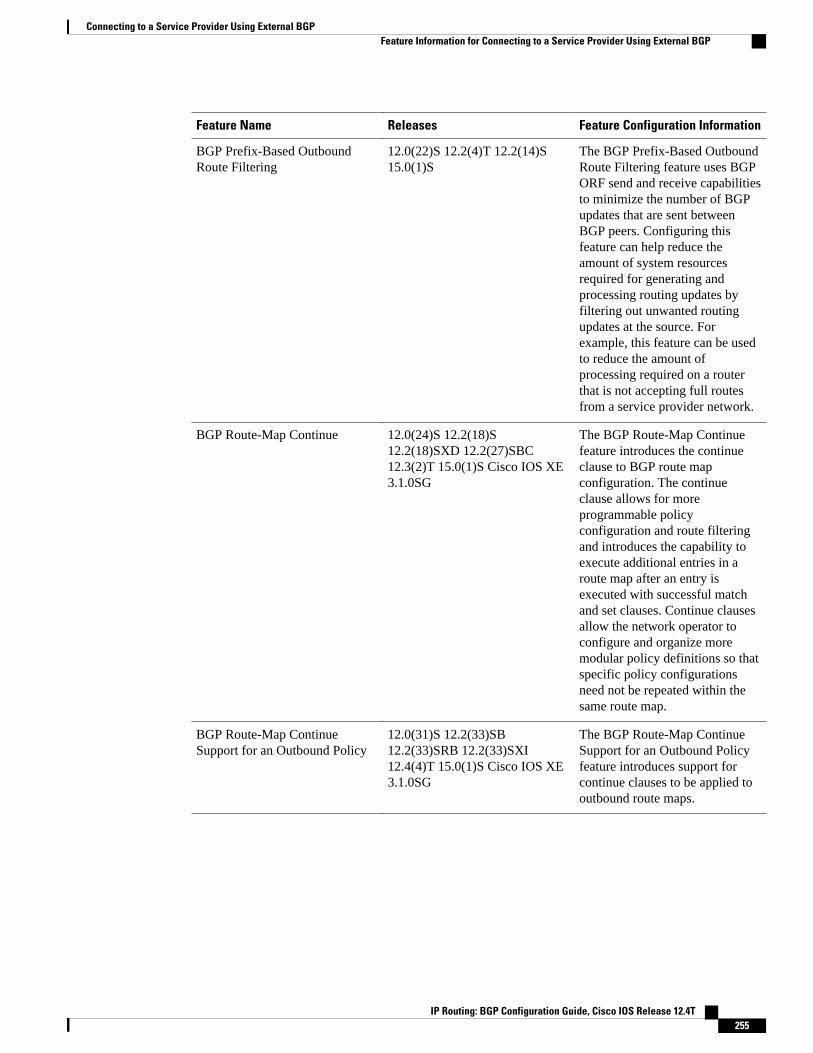
Feature Name Releases Feature Configuration Information
BGP Prefix-Based OutboundRoute Filtering
12.0(22)S 12.2(4)T 12.2(14)S15.0(1)S
The BGP Prefix-Based OutboundRoute Filtering feature uses BGPORF send and receive capabilitiesto minimize the number of BGPupdates that are sent betweenBGP peers. Configuring thisfeature can help reduce theamount of system resourcesrequired for generating andprocessing routing updates byfiltering out unwanted routingupdates at the source. Forexample, this feature can be usedto reduce the amount ofprocessing required on a routerthat is not accepting full routesfrom a service provider network.
BGP Route-Map Continue 12.0(24)S 12.2(18)S12.2(18)SXD 12.2(27)SBC12.3(2)T 15.0(1)S Cisco IOS XE3.1.0SG
The BGP Route-Map Continuefeature introduces the continueclause to BGP route mapconfiguration. The continueclause allows for moreprogrammable policyconfiguration and route filteringand introduces the capability toexecute additional entries in aroute map after an entry isexecuted with successful matchand set clauses. Continue clausesallow the network operator toconfigure and organize moremodular policy definitions so thatspecific policy configurationsneed not be repeated within thesame route map.
BGP Route-Map ContinueSupport for an Outbound Policy
12.0(31)S 12.2(33)SB12.2(33)SRB 12.2(33)SXI12.4(4)T 15.0(1)S Cisco IOS XE3.1.0SG
The BGP Route-Map ContinueSupport for an Outbound Policyfeature introduces support forcontinue clauses to be applied tooutbound route maps.
Connecting to a Service Provider Using External BGPFeature Information for Connecting to a Service Provider Using External BGP
IP Routing: BGP Configuration Guide, Cisco IOS Release 12.4T 255

Feature Name Releases Feature Configuration Information
BGP Route-Map Policy ListSupport
12.0(22)S 12.2(15)T 12.2(18)S12.2(18)SXD 12.2(27)SBC15.0(1)S
The BGP Route-Map Policy ListSupport feature introduces newfunctionality to BGP route maps.This feature adds the capabilityfor a network operator to grouproute map match clauses intonamed lists called policy lists. Apolicy list functions like a macro.When a policy list is referencedin a route map, all of the matchclauses are evaluated andprocessed as if they had beenconfigured directly in the routemap. This enhancementsimplifies the configuration ofBGP routing policy in medium-size and large networks because anetwork operator canpreconfigure policy lists withgroups of match clauses and thenreference these policy lists withindifferent route maps. The networkoperator no longer needs tomanually reconfigure eachrecurring group of match clausesthat occur in multiple route mapentries.
Connecting to a Service Provider Using External BGP Feature Information for Connecting to a Service Provider Using External BGP
IP Routing: BGP Configuration Guide, Cisco IOS Release 12.4T256
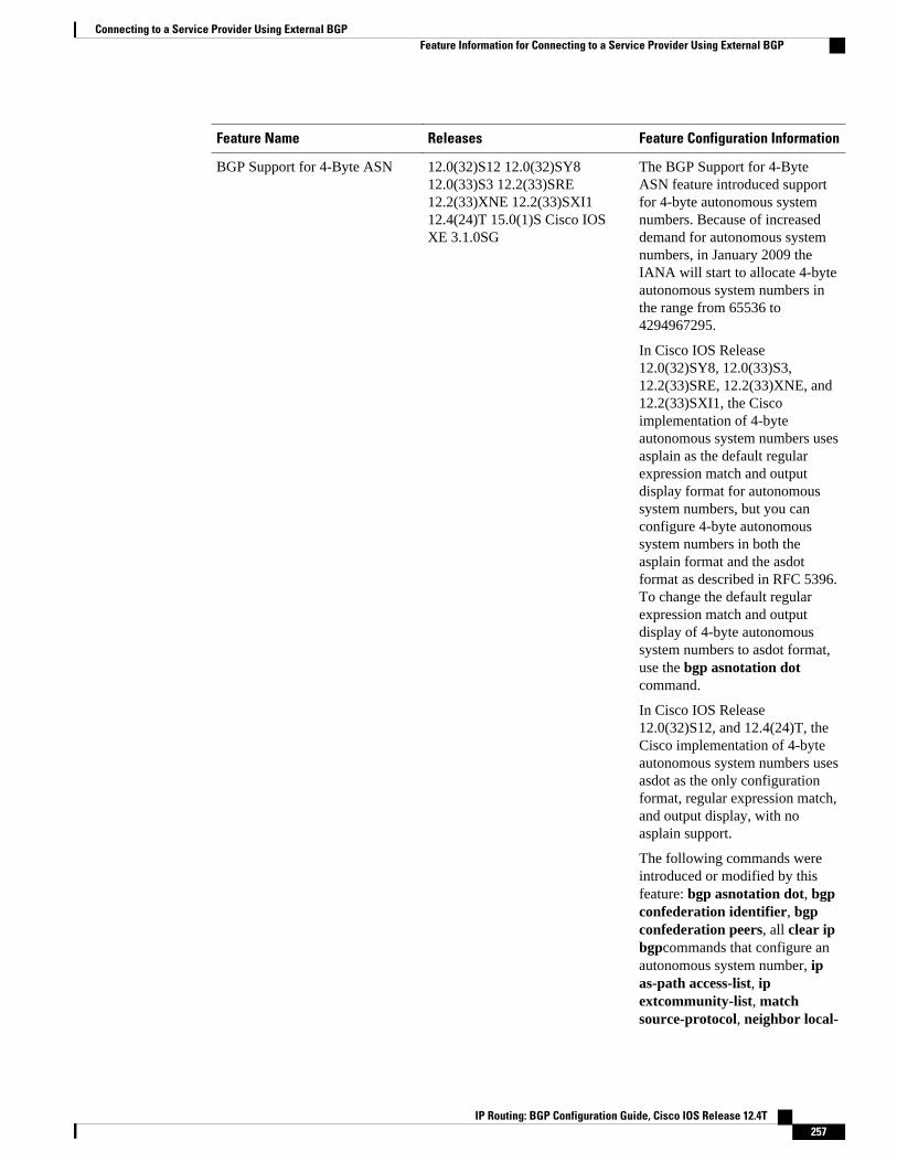
Feature Name Releases Feature Configuration Information
BGP Support for 4-Byte ASN 12.0(32)S12 12.0(32)SY812.0(33)S3 12.2(33)SRE12.2(33)XNE 12.2(33)SXI112.4(24)T 15.0(1)S Cisco IOSXE 3.1.0SG
The BGP Support for 4-ByteASN feature introduced supportfor 4-byte autonomous systemnumbers. Because of increaseddemand for autonomous systemnumbers, in January 2009 theIANA will start to allocate 4-byteautonomous system numbers inthe range from 65536 to4294967295.
In Cisco IOS Release12.0(32)SY8, 12.0(33)S3,12.2(33)SRE, 12.2(33)XNE, and12.2(33)SXI1, the Ciscoimplementation of 4-byteautonomous system numbers usesasplain as the default regularexpression match and outputdisplay format for autonomoussystem numbers, but you canconfigure 4-byte autonomoussystem numbers in both theasplain format and the asdotformat as described in RFC 5396.To change the default regularexpression match and outputdisplay of 4-byte autonomoussystem numbers to asdot format,use the bgp asnotation dotcommand.
In Cisco IOS Release12.0(32)S12, and 12.4(24)T, theCisco implementation of 4-byteautonomous system numbers usesasdot as the only configurationformat, regular expression match,and output display, with noasplain support.
The following commands wereintroduced or modified by thisfeature: bgp asnotation dot, bgpconfederation identifier, bgpconfederation peers, all clear ipbgpcommands that configure anautonomous system number, ipas-path access-list, ipextcommunity-list, matchsource-protocol, neighbor local-
Connecting to a Service Provider Using External BGPFeature Information for Connecting to a Service Provider Using External BGP
IP Routing: BGP Configuration Guide, Cisco IOS Release 12.4T 257

Feature Name Releases Feature Configuration Information
as, neighbor remote-as,neighbor soo, redistribute (IP),router bgp, route-target, set as-path, set extcommunity, setorigin, soo, all show ip bgpcommands that display anautonomous system number, andshow ip extcommunity-list.
BGP Support for NamedExtended Community Lists
12.2(25)S 12.2(27)SBC12.2(33)SRA 12.2(33)SXH12.3(11)T 15.0(1)S
The BGP Support for NamedExtended Community Listsfeature introduces the ability toconfigure extended communitylists using names in addition tothe existing numbered format.
BGP Support for SequencedEntries in Extended CommunityLists
12.2(25)S 12.2(27)SBC12.2(33)SRA 12.2(33)SXH12.3(11)T 15.0(1)S
The BGP Support for SequencedEntries in Extended CommunityLists feature introduces automaticsequencing of individual entriesin BGP extended communitylists. This feature also introducesthe ability to remove orresequence extended communitylist entries without deleting theentire existing extendedcommunity list.
BGP 4 Prefix Filter and InboundRoute Maps
Cisco IOS XE 3.1.0SG
Cisco and the Cisco logo are trademarks or registered trademarks of Cisco and/or its affiliates in the U.S.and other countries. To view a list of Cisco trademarks, go to this URL: www.cisco.com/go/trademarks.Third-party trademarks mentioned are the property of their respective owners. The use of the word partnerdoes not imply a partnership relationship between Cisco and any other company. (1110R)
Any Internet Protocol (IP) addresses and phone numbers used in this document are not intended to beactual addresses and phone numbers. Any examples, command display output, network topology diagrams,and other figures included in the document are shown for illustrative purposes only. Any use of actual IPaddresses or phone numbers in illustrative content is unintentional and coincidental.
Connecting to a Service Provider Using External BGP
IP Routing: BGP Configuration Guide, Cisco IOS Release 12.4T258
Configuring BGP Neighbor Session Options
This module describes configuration tasks to configure various options involving Border GatewayProtocol (BGP) neighbor peer sessions. BGP is an interdomain routing protocol designed to provide loop-free routing between organizations. This module contains tasks that use BGP neighbor session commandsto configure:
• Fast session deactivation• Bidirectional Forwarding Detection (BFD) for BGP IPv6 neighbors• A router to automatically reestablish a BGP neighbor peering session when the peering session has
been disabled or brought down• Options to help an autonomous system migration• TTL Security Check, a lightweight security mechanism to protect External BGP (eBGP) peering
sessions from CPU-utilization-based attacks
• Finding Feature Information, page 259• Prerequisites for Configuring BGP Neighbor Session Options, page 259• Restrictions for Configuring BGP Neighbor Session Options, page 260• Information About Configuring BGP Neighbor Session Options, page 260• How to Configure BGP Neighbor Session Options, page 266• Configuration Examples for BGP Neighbor Session Options, page 299• Where to Go Next, page 305• Additional References, page 305• Feature Information for Configuring BGP Neighbor Session Options, page 307
Finding Feature InformationYour software release may not support all the features documented in this module. For the latest featureinformation and caveats, see the release notes for your platform and software release. To find informationabout the features documented in this module, and to see a list of the releases in which each feature issupported, see the Feature Information Table at the end of this document.
Use Cisco Feature Navigator to find information about platform support and Cisco software image support.To access Cisco Feature Navigator, go to www.cisco.com/go/cfn. An account on Cisco.com is not required.
Prerequisites for Configuring BGP Neighbor Session OptionsBefore configuring advanced BGP features you should be familiar with the "Cisco BGP Overview" moduleand the "Configuring a Basic BGP Network" module.
IP Routing: BGP Configuration Guide, Cisco IOS Release 12.4T 259

Restrictions for Configuring BGP Neighbor Session OptionsA router that runs Cisco IOS software can be configured to run only one BGP routing process and to be amember of only one BGP autonomous system. However, a BGP routing process and autonomous systemcan support multiple address family configurations.
Information About Configuring BGP Neighbor Session Options• BGP Neighbor Sessions, page 260
• BGP Support for Fast Peering Session Deactivation, page 260
• BFD Support of BGP IPv6 Neighbors, page 261
• BGP Neighbor Session Restart After the Max-Prefix Limit Is Reached, page 261
• BGP Network Autonomous System Migration, page 262
• TTL Security Check for BGP Neighbor Sessions, page 263
• BGP Support for TCP Path MTU Discovery per Session, page 265
• BGP Dynamic Neighbors, page 266
BGP Neighbor SessionsBGP is mainly used to connect a local network to an external network to gain access to the Internet or toconnect to other organizations. A BGP-speaking router does not discover another BGP-speaking deviceautomatically. A network administrator usually manually configures the relationships between BGP-speaking routers.
A BGP neighbor device is a BGP-speaking router that has an active TCP connection to another BGP-speaking device. This relationship between BGP devices is often referred to as a peer instead of neighborbecause a neighbor may imply the idea that the BGP devices are directly connected with no other router inbetween. Configuring BGP neighbor or peer sessions uses BGP neighbor session commands so this modulewill prefer the use of the term "neighbor" over "peer."
BGP Support for Fast Peering Session Deactivation• BGP Hold Timer, page 260
• BGP Fast Peering Session Deactivation, page 260
• Selective Address Tracking for BGP Fast Session Deactivation, page 261
BGP Hold TimerBy default, the BGP hold timer is set to run every 180 seconds in Cisco IOS software. This timer value isset as the default to protect the BGP routing process from instability that can be caused by peering sessionswith other routing protocols. BGP routers typically carry large routing tables, so frequent session resets arenot desirable.
BGP Fast Peering Session Deactivation
BGP Neighbor Sessions Restrictions for Configuring BGP Neighbor Session Options
IP Routing: BGP Configuration Guide, Cisco IOS Release 12.4T260

BGP fast peering session deactivation improves BGP convergence and response time to adjacency changeswith BGP neighbors. This feature is event driven and configured on a per-neighbor basis. When this featureis enabled, BGP will monitor the peering session with the specified neighbor. Adjacency changes aredetected and terminated peering sessions are deactivated in between the default or configured BGPscanning interval.
Selective Address Tracking for BGP Fast Session DeactivationIn Cisco IOS Release 12.4(4)T, 12.2(31)SB, 12.2(33)SRB, and later releases, the BGP Selective AddressTracking feature introduced the use of a route map with BGP fast session deactivation. The route-mapkeyword and map-name argument are used with the neighbor fall-over BGP neighbor session command todetermine if a peering session with a BGP neighbor should be reset when a route to the BGP peer changes.The route map is evaluated against the new route, and if a deny statement is returned, the peer session isreset. The route map is not used for session establishment.
Note The neighbor fall-over command is not supported in Cisco IOS Release 15.0(1)SY. The route-map andmap-name keyword-argument pair in the bgp nexthop command are not supported in Cisco IOS Release15.0(1)SY.
Note Only match ip address and match source-protocol commands are supported in the route map. No setcommands or other match commands are supported.
BFD Support of BGP IPv6 NeighborsIn Cisco IOS Release 15.1(2)S and later releases, Bidirectional Forwarding Detection (BFD) can be used totrack fast forwarding path failure of BGP neighbors that have an IPv6 address. BFD is a detection protocolthat is designed to provide fast forwarding path failure detection times for all media types, encapsulations,topologies, and routing protocols. BFD provides faster reconvergence time for BGP after a forwarding pathfailure.
BGP Neighbor Session Restart After the Max-Prefix Limit Is Reached• Prefix Limits and BGP Peering Sessions, page 261
• BGP Neighbor Session Restart with the Maximum Prefix Limit, page 262
Prefix Limits and BGP Peering SessionsThere is a configurable limit on the maximum number of prefixes that a router that is running BGP canreceive from a peer router. This limit is configured with the neighbor maximum-prefix command. Whenthe router receives too many prefixes from a peer router and the maximum-prefix limit is exceeded, thepeering session is disabled or brought down. The session stays down until the network operator manuallybrings the session back up by entering the clear ip bgp command. Entering the clear ip bgp commandclears stored prefixes.
BFD Support of BGP IPv6 NeighborsSelective Address Tracking for BGP Fast Session Deactivation
IP Routing: BGP Configuration Guide, Cisco IOS Release 12.4T 261
BGP Neighbor Session Restart with the Maximum Prefix LimitIn Cisco IOS Release 12.0(22)S, 12.2(15)T, 12.2(18)S, and later releases, the restart keyword was addedto enhance the capabilities of the neighbor maximum-prefix command. This enhancement allows thenetwork operator to configure a router to automatically reestablish a BGP neighbor peering session whenthe peering session has been disabled or brought down. There is configurable time interval at which peeringcan be reestablished automatically. The configurable timer argument for the restart keyword is specified inminutes. The time range is from 1 to 65,535 minutes.
BGP Network Autonomous System Migration• Autonomous System Migration for BGP Networks, page 262
• Dual Autonomous System Support for BGP Network Autonomous System Migration, page 262
• BGP Network Migration to 4-Byte Autonomous System Numbers, page 263
Autonomous System Migration for BGP NetworksAutonomous-system migration can be necessary when a telecommunications or Internet service providerpurchases another network. It is desirable for the provider to be able to integrate the second autonomoussystem without disrupting existing customer peering arrangements. The amount of configuration requiredin the customer networks can make this a cumbersome task that is difficult to complete without disruptingservice.
Dual Autonomous System Support for BGP Network Autonomous System MigrationIn Cisco IOS Release 12.0(29)S, 12.3(14)T, 12.2(33)SXH, and later releases, support was added for dualBGP autonomous system configuration to allow a secondary autonomous system to merge under a primaryautonomous system, without disrupting customer peering sessions. The configuration of this feature istransparent to customer networks. Dual BGP autonomous system configuration allows a router to appear, toexternal peers, as a member of secondary autonomous system during the autonomous system migration.This feature allows the network operator to merge the autonomous systems and then later migratecustomers to new configurations during normal service windows without disrupting existing peeringarrangements.
The neighbor local-as command is used to customize the AS_PATH attribute by adding and removingautonomous system numbers for routes received from eBGP neighbors. This feature allows a router toappear to external peers as a member of another autonomous system for the purpose of autonomous systemnumber migration. This feature simplifies this process of changing the autonomous system number in aBGP network by allowing the network operator to merge a secondary autonomous system into a primaryautonomous system and then later update the customer configurations during normal service windowswithout disrupting existing peering arrangements.
BGP Autonomous System Migration Support for Confederations, Individual Peering Sessions, and PeerGroupings
This feature supports confederations, individual peering sessions, and configurations applied through peergroups and peer templates. If this feature is applied to a group peers, the individual peers cannot becustomized.
BGP Network Autonomous System Migration BGP Neighbor Session Restart with the Maximum Prefix Limit
IP Routing: BGP Configuration Guide, Cisco IOS Release 12.4T262
Ingress Filtering During BGP Autonomous System Migration
Autonomous system path customization increases the possibility that routing loops can be created if suchcustomization is misconfigured. The larger the number of customer peerings, the greater the risk. You canminimize this possibility by applying policies on the ingress interfaces to block the autonomous systemnumber that is in transition or routes that have no local-as configuration.
Caution BGP prepends the autonomous system number from each BGP network that a route traverses to maintainnetwork reachability information and to prevent routing loops. This feature should be configured only forautonomous system migration and should be deconfigured after the transition has been completed. Thisprocedure should be attempted only by an experienced network operator, as routing loops can be createdwith improper configuration.
BGP Network Migration to 4-Byte Autonomous System NumbersThe BGP Support for 4-Byte ASN feature introduced support for 4-byte autonomous system numbers.Because of increased demand for autonomous system numbers, in January 2009 the IANA will start toallocate 4-byte autonomous system numbers in the range from 65536 to 4294967295.
The Cisco implementation of 4-byte autonomous system numbers supports RFC 4893. RFC 4893 wasdeveloped to allow BGP to support a gradual transition from 2-byte autonomous system numbers to 4-byteautonomous system numbers. A new reserved (private) autonomous system number, 23456, was created byRFC 4893 and this number cannot be configured as an autonomous system number in the Cisco IOS CLI.
Migrating your BGP network to 4-byte autonomous system numbers requires some planning. If you areupgrading to an image that supports 4-byte autonomous system numbers, you can still use 2-byteautonomous system numbers. The show command output and regular expression match are not changedand remain in asplain (decimal value) format for 2-byte autonomous system numbers regardless of theformat configured for 4-byte autonomous system numbers.
To ensure a smooth transition, we recommend that all BGP speakers within an autonomous system that isidentified using a 4-byte autonomous system number be upgraded to support 4-byte autonomous systemnumbers.
For details about steps to perform to upgrade a BGP network to full 4-byte autonomous system support, seethe Migration Guide for Explaining 4-Byte Autonomous System white paper.
TTL Security Check for BGP Neighbor Sessions• BGP Support for the TTL Security Check, page 263
• TTL Security Check for BGP Neighbor Sessions, page 264
• TTL Security Check Support for Multihop BGP Neighbor Sessions, page 264
• Benefits of the BGP Support for TTL Security Check, page 264
BGP Support for the TTL Security CheckWhen implemented for BGP, the TTL Security Check feature introduces a lightweight security mechanismto protect eBGP neighbor sessions from CPU utilization-based attacks. These types of attacks are typicallybrute force Denial of Service (DoS) attacks that attempt to disable the network by flooding the networkwith IP packets that contain forged source and destination IP addresses.
TTL Security Check for BGP Neighbor SessionsBGP Network Migration to 4-Byte Autonomous System Numbers
IP Routing: BGP Configuration Guide, Cisco IOS Release 12.4T 263
The TTL Security Check feature protects the eBGP neighbor session by comparing the value in the TTLfield of received IP packets against a hop count that is configured locally for each eBGP neighbor session.If the value in the TTL field of the incoming IP packet is greater than or equal to the locally configuredvalue, the IP packet is accepted and processed normally. If the TTL value in the IP packet is less than thelocally configured value, the packet is silently discarded and no Internet Control Message Protocol (ICMP)message is generated. This is designed behavior; a response to a forged packet is unnecessary.
Although it is possible to forge the TTL field in an IP packet header, accurately forging the TTL count tomatch the TTL count from a trusted peer is impossible unless the network to which the trusted peer belongshas been compromised.
The TTL Security Check feature supports both directly connected neighbor sessions and multihop eBGPneighbor sessions. The BGP neighbor session is not affected by incoming packets that contain invalid TTLvalues. The BGP neighbor session will remain open, and the router will silently discard the invalid packet.The BGP session, however, can still expire if keepalive packets are not received before the session timerexpires.
TTL Security Check for BGP Neighbor SessionsThe BGP Support for TTL Security Check feature is configured with the neighbor ttl-security commandin router configuration mode or address family configuration mode. When this feature is enabled, BGP willestablish or maintain a session only if the TTL value in the IP packet header is equal to or greater than theTTL value configured for the peering session. Enabling this feature secures the eBGP session in theincoming direction only and has no effect on outgoing IP packets or the remote router. The hop-countargument is used to configure the maximum number of hops that separate the two peers. The TTL value isdetermined by the router from the configured hop count. The value for this argument is a number from 1 to254.
TTL Security Check Support for Multihop BGP Neighbor SessionsThe BGP Support for TTL Security Check feature supports both directly connected neighbor sessions andmultihop neighbor sessions. When this feature is configured for a multihop neighbor session, the neighborebgp-multihop router configuration command cannot be configured and is not needed to establish theneighbor session. These commands are mutually exclusive, and only one command is required to establisha multihop neighbor session. If you attempt to configure both commands for the same peering session, anerror message will be displayed in the console.
To configure this feature for an existing multihop session, you must first disable the existing neighborsession with the no neighbor ebgp-multihop command. The multihop neighbor session will be restoredwhen you enable this feature with the neighbor ttl-security command.
This feature should be configured on each participating router. To maximize the effectiveness of thisfeature, the hop-count argument should be strictly configured to match the number of hops between thelocal and external network. However, you should also consider path variation when configuring this featurefor a multihop neighbor session.
Benefits of the BGP Support for TTL Security CheckThe BGP Support for TTL Security Check feature provides an effective and easy-to-deploy solution toprotect eBGP neighbor sessions from CPU utilization-based attacks. When this feature is enabled, a hostcannot attack a BGP session if the host is not a member of the local or remote BGP network or if the host isnot directly connected to a network segment between the local and remote BGP networks. This solutiongreatly reduces the effectiveness of DoS attacks against a BGP autonomous system.
Configuring BGP Neighbor Session Options TTL Security Check for BGP Neighbor Sessions
IP Routing: BGP Configuration Guide, Cisco IOS Release 12.4T264
BGP Support for TCP Path MTU Discovery per Session• Path MTU Discovery, page 265
• BGP Neighbor Session TCP PMTUD, page 265
Path MTU DiscoveryThe IP protocol family was designed to use a wide variety of transmission links. The maximum IP packetlength is 65000 bytes. Most transmission links enforce a smaller maximum packet length limit, called themaximum transmission unit (MTU), which varies with the type of the transmission link. The design of IPaccommodates link packet length limits by allowing intermediate routers to fragment IP packets asnecessary for their outgoing links. The final destination of an IP packet is responsible for reassembling itsfragments as necessary.
All TCP sessions are bounded by a limit on the number of bytes that can be transported in a single packet,and this limit is known as the maximum segment size (MSS). TCP breaks up packets into chunks in atransmit queue before passing packets down to the IP layer. A smaller MSS may not be fragmented at an IPdevice along the path to the destination device, but smaller packets increase the amount of bandwidthneeded to transport the packets. The maximum TCP packet length is determined by both the MTU of theoutbound interface on the source device and the MSS announced by the destination device during the TCPsetup process.
Path MTU discovery (PMTUD) was developed as a solution to the problem of finding the optimal TCPpacket length. PMTUD is an optimization (detailed in RFC 1191) wherein a TCP connection attempts tosend the longest packets that will not be fragmented along the path from source to destination. It does thisby using a flag, don’t fragment (DF), in the IP packet. This flag is supposed to alter the behavior of anintermediate router that cannot send the packet across a link because it is too long. Normally the flag is off,and the router should fragment the packet and send the fragments. If a router tries to forward an IPdatagram, with the DF bit set, to a link that has a lower MTU than the size of the packet, the router willdrop the packet and return an ICMP Destination Unreachable message to the source of this IP datagram,with the code indicating "fragmentation needed and DF set." When the source device receives the ICMPmessage, it will lower the send MSS, and when TCP retransmits the segment, it will use the smallersegment size.
BGP Neighbor Session TCP PMTUDTCP path MTU discovery is enabled by default for all BGP neighbor sessions, but there are situations whenyou may want to disable TCP path MTU discovery for one or all BGP neighbor sessions. AlthoughPMTUD works well for larger transmission links (for example, Packet over Sonet links), a badlyconfigured TCP implementation or a firewall may slow or stop the TCP connections from forwarding anypackets. In this type of situation, you may need to disable TCP path MTU discovery. In Cisco IOS Release12.2(33)SRA, 12.2(31)SB, 12.2(33)SXH, 12.4(20)T, and later releases, configuration options wereintroduced to permit TCP path MTU discovery to be disabled, or subsequently reenabled, either for a singleBGP neighbor session or for all BGP sessions. To disable the TCP path MTU discovery globally for allBGP neighbors, use the no bgp transport path-mtu-discovery command in router configuration mode. Todisable the TCP path MTU discovery for a single neighbor, use the no neighbor transport path-mtu-discovery command in router or address family configuration modes. For more details, see the DisablingTCP Path MTU Discovery Globally for All BGP Sessions, page 283 or the Disabling TCP Path MTUDiscovery for a Single BGP Neighbor, page 285.
BGP Support for TCP Path MTU Discovery per SessionPath MTU Discovery
IP Routing: BGP Configuration Guide, Cisco IOS Release 12.4T 265
BGP Dynamic NeighborsSupport for the BGP Dynamic Neighbors feature was introduced in Cisco IOS Release 12.2(33)SXH on theCisco Catalyst 6500 series switches. BGP dynamic neighbor support allows BGP peering to a group ofremote neighbors that are defined by a range of IP addresses. Each range can be configured as a subnet IPaddress. BGP dynamic neighbors are configured using a range of IP addresses and BGP peer groups.
After a subnet range is configured for a BGP peer group and a TCP session is initiated by another router foran IP address in the subnet range, a new BGP neighbor is dynamically created as a member of that group.After the initial configuration of subnet ranges and activation of the peer group (referred to as a listen rangegroup ), dynamic BGP neighbor creation does not require any further CLI configuration on the initialrouter. Other routers can establish a BGP session with the initial router, but the initial router need notestablish a BGP session to other routers if the IP address of the remote peer used for the BGP session is notwithin the configured range.
To support the BGP Dynamic Neighbors feature, the output for the show ip bgp neighbors, show ip bgppeer-group, and show ip bgp summary commands was updated to display information about dynamicneighbors.
A dynamic BGP neighbor will inherit any configuration for the peer group. In larger BGP networks,implementing BGP dynamic neighbors can reduce the amount and complexity of CLI configuration andsave CPU and memory usage. Only IPv4 peering is supported.
How to Configure BGP Neighbor Session Options• Configuring Fast Session Deactivation, page 266
• Configuring BFD for BGP IPv6 Neighbors, page 270
• Configuring a Router to Reestablish a Neighbor Session After the Maximum Prefix Limit Has BeenExceeded, page 273
• Configuring Dual-AS Peering for Network Migration, page 277
• Configuring the TTL Security Check for BGP Neighbor Sessions, page 279
• Configuring BGP Support for TCP Path MTU Discovery per Session, page 283
• Implementing BGP Dynamic Neighbors Using Subnet Ranges, page 292
Configuring Fast Session DeactivationThe tasks in this section show how to configure BGP next-hop address tracking. BGP next-hop addresstracking significantly improves the response time of BGP to next-hop changes in the RIB. However,unstable Interior Gateway Protocol (IGP) peers can introduce instability to BGP neighbor sessions. Werecommend that you aggressively dampen unstable IGP peering sessions to reduce the possible impact toBGP. For more details about route dampening, see the "Configuring Internal BGP Features" module.
• Configuring Fast Session Deactivation for a BGP Neighbor, page 266
• Configuring Selective Address Tracking for Fast Session Deactivation, page 268
Configuring Fast Session Deactivation for a BGP NeighborPerform this task to establish a peering session with a BGP neighbor and then configure the peering sessionfor fast session deactivation to improve the network convergence time if the peering session is deactivated.
BGP Dynamic Neighbors How to Configure BGP Neighbor Session Options
IP Routing: BGP Configuration Guide, Cisco IOS Release 12.4T266
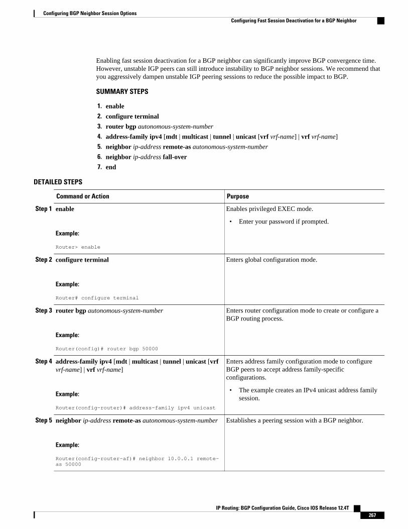
Enabling fast session deactivation for a BGP neighbor can significantly improve BGP convergence time.However, unstable IGP peers can still introduce instability to BGP neighbor sessions. We recommend thatyou aggressively dampen unstable IGP peering sessions to reduce the possible impact to BGP.
SUMMARY STEPS
1. enable
2. configure terminal
3. router bgp autonomous-system-number
4. address-family ipv4 [mdt | multicast | tunnel | unicast [vrf vrf-name] | vrf vrf-name]
5. neighbor ip-address remote-as autonomous-system-number
6. neighbor ip-address fall-over
7. end
DETAILED STEPS
Command or Action Purpose
Step 1 enable
Example:
Router> enable
Enables privileged EXEC mode.
• Enter your password if prompted.
Step 2 configure terminal
Example:
Router# configure terminal
Enters global configuration mode.
Step 3 router bgp autonomous-system-number
Example:
Router(config)# router bgp 50000
Enters router configuration mode to create or configure aBGP routing process.
Step 4 address-family ipv4 [mdt | multicast | tunnel | unicast [vrfvrf-name] | vrf vrf-name]
Example:
Router(config-router)# address-family ipv4 unicast
Enters address family configuration mode to configureBGP peers to accept address family-specificconfigurations.
• The example creates an IPv4 unicast address familysession.
Step 5 neighbor ip-address remote-as autonomous-system-number
Example:
Router(config-router-af)# neighbor 10.0.0.1 remote-as 50000
Establishes a peering session with a BGP neighbor.
Configuring BGP Neighbor Session OptionsConfiguring Fast Session Deactivation for a BGP Neighbor
IP Routing: BGP Configuration Guide, Cisco IOS Release 12.4T 267

Command or Action Purpose
Step 6 neighbor ip-address fall-over
Example:
Router(config-router-af)# neighbor 10.0.0.1 fall-over
Configures the BGP peering to use fast sessiondeactivation.
• BGP will remove all routes learned through this peerif the session is deactivated.
Step 7 end
Example:
Router(config-router-af)# end
Exits configuration mode and enters privileged EXECmode.
Configuring Selective Address Tracking for Fast Session DeactivationPerform this task to configure selective address tracking for fast session deactivation. The optional route-map keyword and map-name argument of the neighbor fall-over command are used to determine if apeering session with a BGP neighbor should be deactivated (reset) when a route to the BGP peer changes.The route map is evaluated against the new route, and if a deny statement is returned, the peer session isreset.
Note Only match ip address and match source-protocol commands are supported in the route map. No setcommands or other match commands are supported.
SUMMARY STEPS
1. enable
2. configure terminal
3. router bgp autonomous-system-number
4. neighbor {ip-address| peer-group-name} remote-as autonomous-system-number
5. neighbor ip-address fall-over [route-map map-name]
6. exit
7. ip prefix-list list-name [seq seq-value ]{deny network / length | permit network / length}[ge ge-value][le le-value]
8. route-map map-name [permit | deny][sequence-number]
9. match ip address prefix-list prefix-list-name [prefix-list-name...]
10. end
Configuring BGP Neighbor Session Options Configuring Selective Address Tracking for Fast Session Deactivation
IP Routing: BGP Configuration Guide, Cisco IOS Release 12.4T268

DETAILED STEPS
Command or Action Purpose
Step 1 enable
Example:
Router> enable
Enables privileged EXEC mode.
• Enter your password if prompted.
Step 2 configure terminal
Example:
Router# configure terminal
Enters global configuration mode.
Step 3 router bgp autonomous-system-number
Example:
Router(config)# router bgp 45000
Enters router configuration mode for the specified routing process.
Step 4 neighbor {ip-address| peer-group-name} remote-asautonomous-system-number
Example:
Router(config-router)# neighbor 192.168.1.2 remote-as 40000
Adds the IP address or peer group name of the neighbor in thespecified autonomous system to the IPv4 multiprotocol BGPneighbor table of the local router.
Step 5 neighbor ip-address fall-over [route-map map-name]
Example:
Router(config-router)# neighbor 192.168.1.2 fall-over route-map CHECK-NBR
Applies a route map when a route to the BGP changes.
• In this example, the route map named CHECK-NBR isapplied when the route to neighbor 192.168.1.2 changes.
Step 6 exit
Example:
Router(config-router)# exit
Exits router configuration mode and enters global configurationmode.
Configuring BGP Neighbor Session OptionsConfiguring Selective Address Tracking for Fast Session Deactivation
IP Routing: BGP Configuration Guide, Cisco IOS Release 12.4T 269

Command or Action Purpose
Step 7 ip prefix-list list-name [seq seq-value ]{deny network / length | permit network / length}[ge ge-value] [le le-value]
Example:
Router(config)# ip prefix-list FILTER28 seq 5 permit 0.0.0.0/0 ge 28
Creates a prefix list for BGP next-hop route filtering.
• Selective next-hop route filtering supports prefix- lengthmatching or source-protocol matching on a per-addressfamily basis.
• The example creates a prefix list named FILTER28 thatpermits routes only if the mask length is greater than or equalto 28.
Step 8 route-map map-name [permit | deny][sequence-number]
Example:
Router(config)# route-map CHECK-NBR permit 10
Configures a route map and enters route-map configuration mode.
• In this example, a route map named CHECK-NBR is created.If there is an IP address match in the following matchcommand, the IP address will be permitted.
Step 9 match ip address prefix-list prefix-list-name[prefix-list-name...]
Example:
Router(config-route-map)# match ip address prefix-list FILTER28
Matches the IP addresses in the specified prefix list.
• Use the prefix-list-name argument to specify the name of aprefix list. The ellipsis means that more than one prefix listcan be specified.
Note Only the syntax applicable to this task is used in thisexample. For more details, see the Cisco IOS IP Routing:BGP Command Reference.
Step 10 end
Example:
Router(config-route-map)# end
Exits route-map configuration mode and enters privileged EXECmode.
• What to Do Next, page 270
What to Do Next
The BGP Support for Next-Hop Address Tracking feature improves the response time of BGP to next-hopchanges for routes installed in the RIB, which can also improve overall BGP convergence. For informationabout BGP next-hop address tracking, see the "Configuring Advanced BGP Features" module.
Configuring BFD for BGP IPv6 NeighborsIn Cisco IOS Release 15.1(2)S and later releases, Bidirectional Forwarding Detection (BFD) can be usedfor BGP neighbors that have an IPv6 address.
Once it has been verified that BFD neighbors are up, the show bgp ipv6 unicast neighborscommand willindicate that BFD is being used to detect fast fallover on the specified neighbor.
Configuring BFD for BGP IPv6 Neighbors What to Do Next
IP Routing: BGP Configuration Guide, Cisco IOS Release 12.4T270
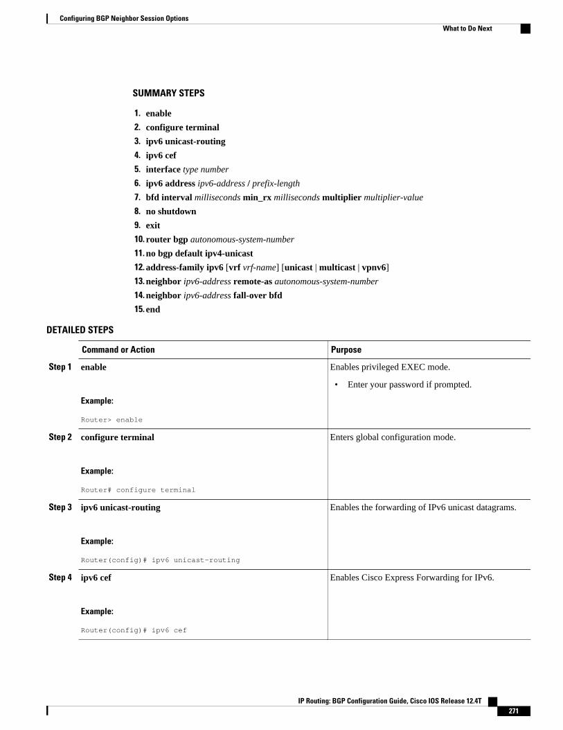
SUMMARY STEPS
1. enable
2. configure terminal
3. ipv6 unicast-routing
4. ipv6 cef
5. interface type number
6. ipv6 address ipv6-address / prefix-length
7. bfd interval milliseconds min_rx milliseconds multiplier multiplier-value
8. no shutdown
9. exit
10. router bgp autonomous-system-number
11. no bgp default ipv4-unicast
12. address-family ipv6 [vrf vrf-name] [unicast | multicast | vpnv6]
13. neighbor ipv6-address remote-as autonomous-system-number
14. neighbor ipv6-address fall-over bfd
15. end
DETAILED STEPS
Command or Action Purpose
Step 1 enable
Example:
Router> enable
Enables privileged EXEC mode.
• Enter your password if prompted.
Step 2 configure terminal
Example:
Router# configure terminal
Enters global configuration mode.
Step 3 ipv6 unicast-routing
Example:
Router(config)# ipv6 unicast-routing
Enables the forwarding of IPv6 unicast datagrams.
Step 4 ipv6 cef
Example:
Router(config)# ipv6 cef
Enables Cisco Express Forwarding for IPv6.
Configuring BGP Neighbor Session OptionsWhat to Do Next
IP Routing: BGP Configuration Guide, Cisco IOS Release 12.4T 271
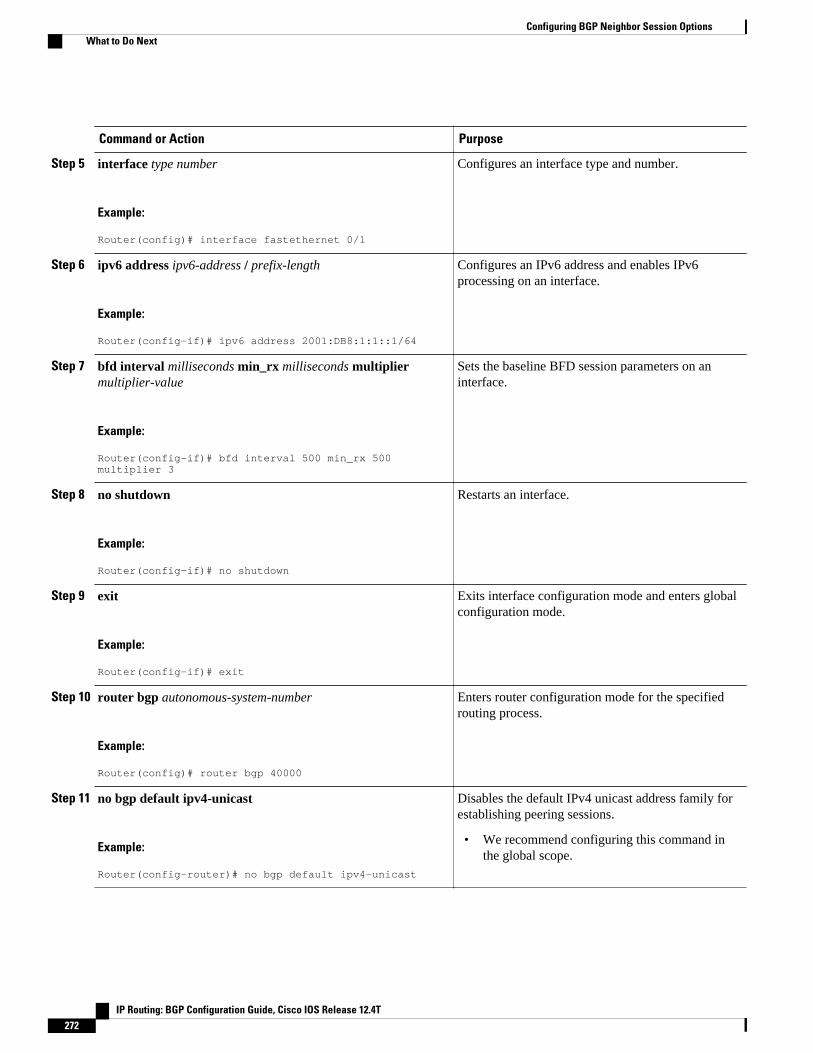
Command or Action Purpose
Step 5 interface type number
Example:
Router(config)# interface fastethernet 0/1
Configures an interface type and number.
Step 6 ipv6 address ipv6-address / prefix-length
Example:
Router(config-if)# ipv6 address 2001:DB8:1:1::1/64
Configures an IPv6 address and enables IPv6processing on an interface.
Step 7 bfd interval milliseconds min_rx milliseconds multipliermultiplier-value
Example:
Router(config-if)# bfd interval 500 min_rx 500 multiplier 3
Sets the baseline BFD session parameters on aninterface.
Step 8 no shutdown
Example:
Router(config-if)# no shutdown
Restarts an interface.
Step 9 exit
Example:
Router(config-if)# exit
Exits interface configuration mode and enters globalconfiguration mode.
Step 10 router bgp autonomous-system-number
Example:
Router(config)# router bgp 40000
Enters router configuration mode for the specifiedrouting process.
Step 11 no bgp default ipv4-unicast
Example:
Router(config-router)# no bgp default ipv4-unicast
Disables the default IPv4 unicast address family forestablishing peering sessions.
• We recommend configuring this command inthe global scope.
Configuring BGP Neighbor Session Options What to Do Next
IP Routing: BGP Configuration Guide, Cisco IOS Release 12.4T272

Command or Action Purpose
Step 12 address-family ipv6 [vrf vrf-name] [unicast | multicast | vpnv6]
Example:
Router(config-router)# address-family ipv6
Enters address family configuration mode andenables IPv6 addressing.
Step 13 neighbor ipv6-address remote-as autonomous-system-number
Example:
Router(config-router-af)# neighbor 2001:DB8:2:1::4 remote-as 45000
Adds the IP address of the neighbor in the specifiedautonomous system to the IPv6 BGP neighbor tableof the local router.
Step 14 neighbor ipv6-address fall-over bfd
Example:
Router(config-router)# neighbor 2001:DB8:2:1::4 fall-over bfd
Enables BGP to monitor the peering session of anIPv6 neighbor using BFD.
Step 15 end
Example:
Router(config-router)# end
Exits configuration mode and enters privilegedEXEC mode.
Configuring a Router to Reestablish a Neighbor Session After the MaximumPrefix Limit Has Been Exceeded
Perform this task to configure the time interval at which a BGP neighbor session is reestablished by arouter when the number of prefixes that have been received from a BGP peer has exceeded the maximumprefix limit.
The network operator can configure a router that is running BGP to automatically reestablish a neighborsession that has been brought down because the configured maximum-prefix limit has been exceeded. Nointervention from the network operator is required when this feature is enabled.
Configuring a Router to Reestablish a Neighbor Session After the Maximum Prefix Limit Has Been ExceededWhat to Do Next
IP Routing: BGP Configuration Guide, Cisco IOS Release 12.4T 273

Note This task attempts to reestablish a disabled BGP neighbor session at the configured time interval that isspecified by the network operator. However, the configuration of the restart timer alone cannot change orcorrect a peer that is sending an excessive number of prefixes. The network operator will need toreconfigure the maximum-prefix limit or reduce the number of prefixes that are sent from the peer. A peerthat is configured to send too many prefixes can cause instability in the network, where an excessivenumber of prefixes are rapidly advertised and withdrawn. In this case, the warning-only keyword of theneighbor maximum-prefix command can be configured to disable the restart capability, while the networkoperator corrects the underlying problem.
SUMMARY STEPS
1. enable
2. configure terminal
3. router bgp autonomous-system-number
4. neighbor {ip-address | peer-group-name} maximum-prefix maximum [threshold] [restart minutes][warning-only]
5. end
6. show ip bgp neighbors ip-address
DETAILED STEPS
Command or Action Purpose
Step 1 enable
Example:
Router> enable
Enables privileged EXEC mode.
• Enter your password if prompted.
Step 2 configure terminal
Example:
Router# configure terminal
Enters global configuration mode.
Step 3 router bgp autonomous-system-number
Example:
Router(config)# router bgp 101
Enters router configuration mode and creates a BGP routing process.
Configuring BGP Neighbor Session Options What to Do Next
IP Routing: BGP Configuration Guide, Cisco IOS Release 12.4T274

Command or Action Purpose
Step 4 neighbor {ip-address | peer-group-name}maximum-prefix maximum [threshold][restart minutes] [warning-only]
Example:
Router(config-router)# neighbor 10.4.9.5 maximum-prefix 1000 90 restart 60
Configures the maximum-prefix limit on a router that is running BGP.
• Use the restart keyword and minutes argument to configure the router toautomatically reestablish a neighbor session that has been disabledbecause the maximum-prefix limit has been exceeded. The configurablerange of minutesis from 1 to 65535 minutes.
• Use the warning-only keyword to configure the router to disable therestart capability to allow you to fix a peer that is sending too manyprefixes.
Note If the minutesargument is not configured, the disabled session will staydown after the maximum-prefix limit is exceeded. This is the defaultbehavior.
Step 5 end
Example:
Router(config-router)# end
Exits configuration mode and enters privilaged EXEC mode.
Step 6 show ip bgp neighbors ip-address
Example:
Router# show ip bgp neighbors 10.4.9.5
(Optional) Displays information about the TCP and BGP connections toneighbors.
• In this example, the output from this command will display themaximum prefix limit for the specified neighbor and the configuredrestart timer value.
Note Only the syntax applicable to this task is used in this example. Formore details, see the Cisco IOS IP Routing: BGP Command Reference.
Examples
The following example output from the show ip bgp neighbors command verifies that a router has beenconfigured to automatically reestablish disabled neighbor sessions. The output shows that the maximumprefix limit for neighbor 10.4.9.5 is set to 1000 prefixes, the restart threshold is set to 90 percent, and therestart interval is set at 60 minutes.
Router# show ip bgp neighbors 10.4.9.5 BGP neighbor is 10.4.9.5, remote AS 101, internal link BGP version 4, remote router ID 10.4.9.5 BGP state = Established, up for 2w2d Last read 00:00:14, hold time is 180, keepalive interval is 60 seconds Neighbor capabilities: Route refresh: advertised and received(new) Address family IPv4 Unicast: advertised and received Message statistics: InQ depth is 0 OutQ depth is 0 Sent Rcvd Opens: 1 1 Notifications: 0 0 Updates: 0 0 Keepalives: 23095 23095 Route Refresh: 0 0 Total: 23096 23096
Configuring BGP Neighbor Session OptionsWhat to Do Next
IP Routing: BGP Configuration Guide, Cisco IOS Release 12.4T 275
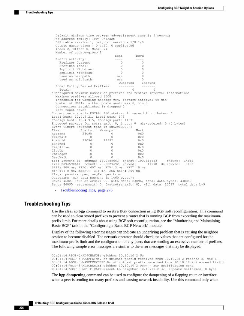
Default minimum time between advertisement runs is 5 seconds For address family: IPv4 Unicast BGP table version 1, neighbor versions 1/0 1/0 Output queue sizes : 0 self, 0 replicated Index 2, Offset 0, Mask 0x4 Member of update-group 2 Sent Rcvd Prefix activity: ---- ---- Prefixes Current: 0 0 Prefixes Total: 0 0 Implicit Withdraw: 0 0 Explicit Withdraw: 0 0 Used as bestpath: n/a 0 Used as multipath: n/a 0 Outbound Inbound Local Policy Denied Prefixes: -------- ------- Total: 0 0!Configured maximum number of prefixes and restart interval information! Maximum prefixes allowed 1000 Threshold for warning message 90%, restart interval 60 min Number of NLRIs in the update sent: max 0, min 0 Connections established 1; dropped 0 Last reset neverConnection state is ESTAB, I/O status: 1, unread input bytes: 0Local host: 10.4.9.21, Local port: 179Foreign host: 10.4.9.5, Foreign port: 11871Enqueued packets for retransmit: 0, input: 0 mis-ordered: 0 (0 bytes)Event Timers (current time is 0x5296BD2C):Timer Starts Wakeups NextRetrans 23098 0 0x0TimeWait 0 0 0x0AckHold 23096 22692 0x0SendWnd 0 0 0x0KeepAlive 0 0 0x0GiveUp 0 0 0x0PmtuAger 0 0 0x0DeadWait 0 0 0x0iss: 1900546793 snduna: 1900985663 sndnxt: 1900985663 sndwnd: 14959irs: 2894590641 rcvnxt: 2895029492 rcvwnd: 14978 delrcvwnd: 1406SRTT: 300 ms, RTTO: 607 ms, RTV: 3 ms, KRTT: 0 msminRTT: 0 ms, maxRTT: 316 ms, ACK hold: 200 msFlags: passive open, nagle, gen tcbsDatagrams (max data segment is 1460 bytes):Rcvd: 46021 (out of order: 0), with data: 23096, total data bytes: 438850Sent: 46095 (retransmit: 0, fastretransmit: 0), with data: 23097, total data by9
• Troubleshooting Tips, page 276
Troubleshooting TipsUse the clear ip bgp command to resets a BGP connection using BGP soft reconfiguration. This commandcan be used to clear stored prefixes to prevent a router that is running BGP from exceeding the maximum-prefix limit. For more details about using BGP soft reconfiguration, see the "Monitoring and MaintainingBasic BGP" task in the "Configuring a Basic BGP Network" module.
Display of the following error messages can indicate an underlying problem that is causing the neighborsession to become disabled. The network operator should check the values that are configured for themaximum-prefix limit and the configuration of any peers that are sending an excessive number of prefixes.The following sample error messages are similar to the error messages that may be displayed:
00:01:14:%BGP-5-ADJCHANGE:neighbor 10.10.10.2 Up00:01:14:%BGP-4-MAXPFX:No. of unicast prefix received from 10.10.10.2 reaches 5, max 600:01:14:%BGP-3-MAXPFXEXCEED:No.of unicast prefix received from 10.10.10.2:7 exceed limit600:01:14:%BGP-5-ADJCHANGE:neighbor 10.10.10.2 Down - BGP Notification sent00:01:14:%BGP-3-NOTIFICATION:sent to neighbor 10.10.10.2 3/1 (update malformed) 0 byte
The bgp dampening command can be used to configure the dampening of a flapping route or interfacewhen a peer is sending too many prefixes and causing network instability. Use this command only when
Configuring BGP Neighbor Session Options Troubleshooting Tips
IP Routing: BGP Configuration Guide, Cisco IOS Release 12.4T276
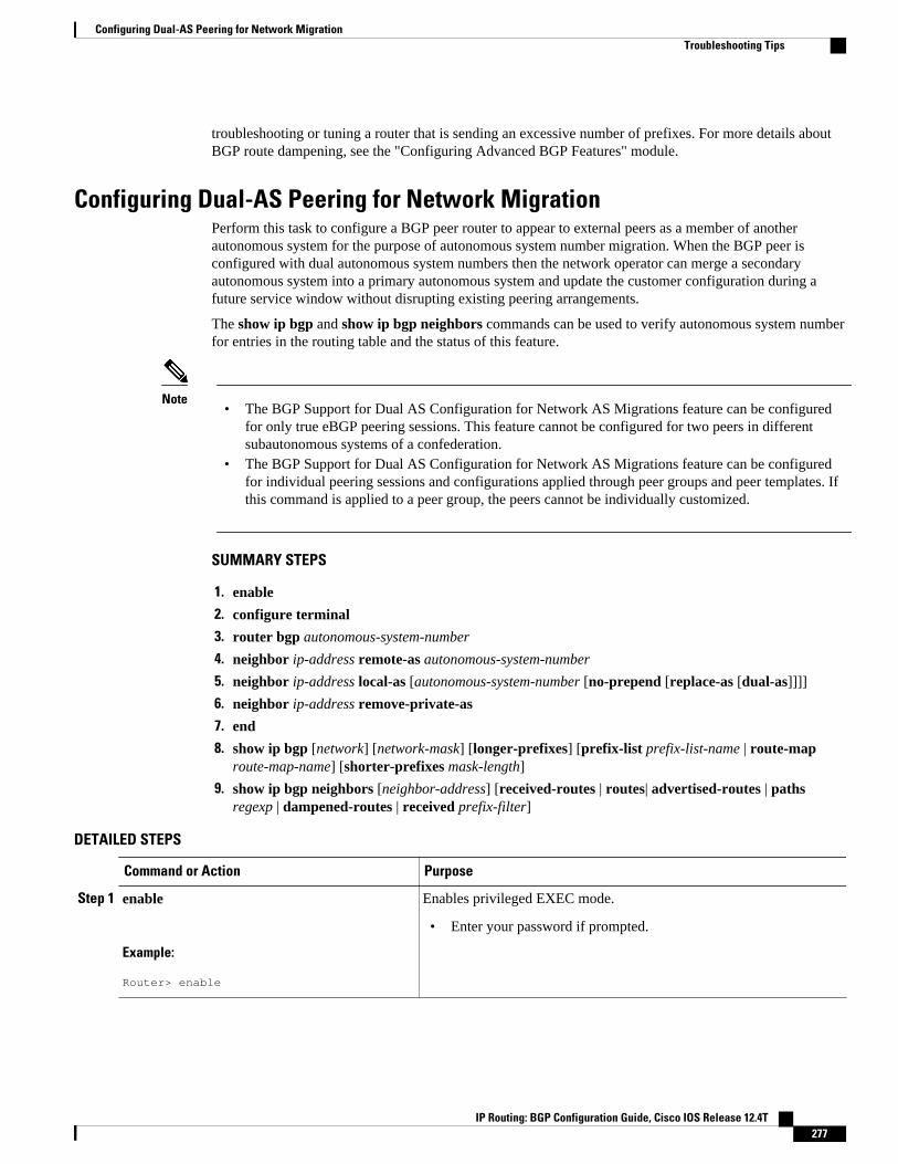
troubleshooting or tuning a router that is sending an excessive number of prefixes. For more details aboutBGP route dampening, see the "Configuring Advanced BGP Features" module.
Configuring Dual-AS Peering for Network MigrationPerform this task to configure a BGP peer router to appear to external peers as a member of anotherautonomous system for the purpose of autonomous system number migration. When the BGP peer isconfigured with dual autonomous system numbers then the network operator can merge a secondaryautonomous system into a primary autonomous system and update the customer configuration during afuture service window without disrupting existing peering arrangements.
The show ip bgp and show ip bgp neighbors commands can be used to verify autonomous system numberfor entries in the routing table and the status of this feature.
Note• The BGP Support for Dual AS Configuration for Network AS Migrations feature can be configured
for only true eBGP peering sessions. This feature cannot be configured for two peers in differentsubautonomous systems of a confederation.
• The BGP Support for Dual AS Configuration for Network AS Migrations feature can be configuredfor individual peering sessions and configurations applied through peer groups and peer templates. Ifthis command is applied to a peer group, the peers cannot be individually customized.
SUMMARY STEPS
1. enable
2. configure terminal
3. router bgp autonomous-system-number
4. neighbor ip-address remote-as autonomous-system-number
5. neighbor ip-address local-as [autonomous-system-number [no-prepend [replace-as [dual-as]]]]
6. neighbor ip-address remove-private-as
7. end
8. show ip bgp [network] [network-mask] [longer-prefixes] [prefix-list prefix-list-name | route-maproute-map-name] [shorter-prefixes mask-length]
9. show ip bgp neighbors [neighbor-address] [received-routes | routes| advertised-routes | pathsregexp | dampened-routes | received prefix-filter]
DETAILED STEPS
Command or Action Purpose
Step 1 enable
Example:
Router> enable
Enables privileged EXEC mode.
• Enter your password if prompted.
Configuring Dual-AS Peering for Network MigrationTroubleshooting Tips
IP Routing: BGP Configuration Guide, Cisco IOS Release 12.4T 277

Command or Action Purpose
Step 2 configure terminal
Example:
Router# configure terminal
Enters global configuration mode.
Step 3 router bgp autonomous-system-number
Example:
Router(config)# router bgp 40000
Enters router configuration mode, and creates a BGP routing process.
Step 4 neighbor ip-address remote-as autonomous-system-number
Example:
Router(config-router)# neighbor 10.0.0.1 remote-as 45000
Establishes a peering session with a BGP neighbor.
Step 5 neighbor ip-address local-as [autonomous-system-number [no-prepend [replace-as [dual-as]]]]
Example:
Router(config-router)# neighbor 10.0.0.1 local-as 50000 no-prepend replace-as dual-as
Customizes the AS_PATH attribute for routes received from an eBGPneighbor.
• The replace-as keyword is used to prepend only the localautonomous system number (as configured with the ip-addressargument) to the AS_PATH attribute. The autonomous systemnumber from the local BGP routing process is not prepended.
• The dual-as keyword is used to configure the eBGP neighbor toestablish a peering session using the real autonomous-systemnumber (from the local BGP routing process) or by using theautonomous system number configured with the ip-addressargument (local-as).
• The example configures the peering session with the 10.0.0.1neighbor to accept the real autonomous system number and thelocal-as number.
Step 6 neighbor ip-address remove-private-as
Example:
Router(config-router)# neighbor 10.0.0.1 remove-private-as
(Optional) Removes private autonomous system numbers fromoutbound routing updates.
• This command can be used with the replace-as functionality toremove the private autonomous system number and replace it withan external autonomous system number.
• Private autonomous system numbers (64512 to 65535) areautomatically removed from the AS_PATH attribute when thiscommand is configured.
Configuring BGP Neighbor Session Options Troubleshooting Tips
IP Routing: BGP Configuration Guide, Cisco IOS Release 12.4T278
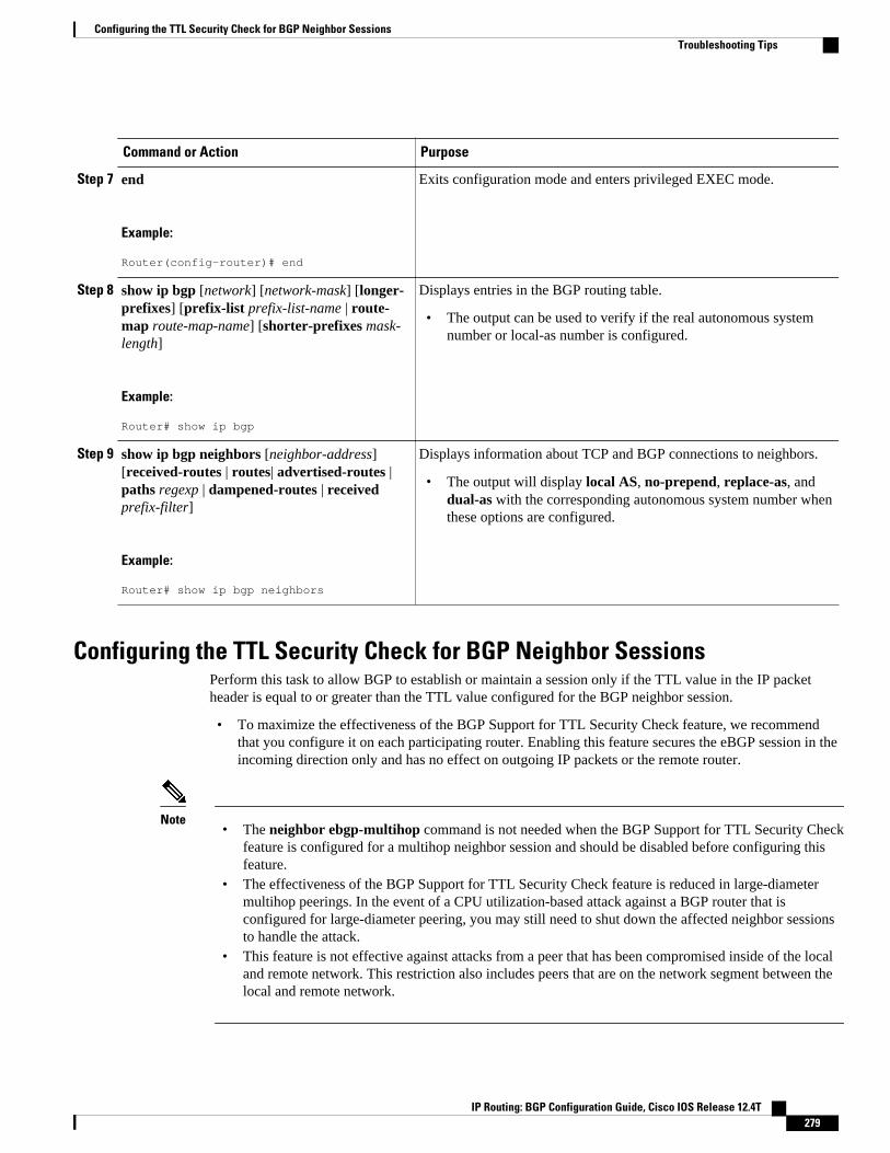
Command or Action Purpose
Step 7 end
Example:
Router(config-router)# end
Exits configuration mode and enters privileged EXEC mode.
Step 8 show ip bgp [network] [network-mask] [longer-prefixes] [prefix-list prefix-list-name | route-map route-map-name] [shorter-prefixes mask-length]
Example:
Router# show ip bgp
Displays entries in the BGP routing table.
• The output can be used to verify if the real autonomous systemnumber or local-as number is configured.
Step 9 show ip bgp neighbors [neighbor-address][received-routes | routes| advertised-routes |paths regexp | dampened-routes | receivedprefix-filter]
Example:
Router# show ip bgp neighbors
Displays information about TCP and BGP connections to neighbors.
• The output will display local AS, no-prepend, replace-as, anddual-as with the corresponding autonomous system number whenthese options are configured.
Configuring the TTL Security Check for BGP Neighbor SessionsPerform this task to allow BGP to establish or maintain a session only if the TTL value in the IP packetheader is equal to or greater than the TTL value configured for the BGP neighbor session.
• To maximize the effectiveness of the BGP Support for TTL Security Check feature, we recommendthat you configure it on each participating router. Enabling this feature secures the eBGP session in theincoming direction only and has no effect on outgoing IP packets or the remote router.
Note• The neighbor ebgp-multihop command is not needed when the BGP Support for TTL Security Check
feature is configured for a multihop neighbor session and should be disabled before configuring thisfeature.
• The effectiveness of the BGP Support for TTL Security Check feature is reduced in large-diametermultihop peerings. In the event of a CPU utilization-based attack against a BGP router that isconfigured for large-diameter peering, you may still need to shut down the affected neighbor sessionsto handle the attack.
• This feature is not effective against attacks from a peer that has been compromised inside of the localand remote network. This restriction also includes peers that are on the network segment between thelocal and remote network.
Configuring the TTL Security Check for BGP Neighbor SessionsTroubleshooting Tips
IP Routing: BGP Configuration Guide, Cisco IOS Release 12.4T 279

SUMMARY STEPS
1. enable
2. trace [protocol] destination
3. configure terminal
4. router bgp autonomous-system-number
5. neighbor ip-address ttl-security hops hop-count
6. end
7. show running-config
8. show ip bgp neighbors [ip-address]
DETAILED STEPS
Command or Action Purpose
Step 1 enable
Example:
Router> enable
Enables privileged EXEC mode.
• Enter your password if prompted.
Step 2 trace [protocol] destination
Example:
Router# trace ip 10.1.1.1
Discovers the routes of the specified protocol that packets will actually take whentraveling to their destination.
• Enter the trace command to determine the number of hops to the specifiedpeer.
Step 3 configure terminal
Example:
Router# configure terminal
Enters global configuration mode.
Step 4 router bgp autonomous-system-number
Example:
Router(config)# router bgp 65000
Enters router configuration mode, and creates a BGP routing process.
Configuring BGP Neighbor Session Options Troubleshooting Tips
IP Routing: BGP Configuration Guide, Cisco IOS Release 12.4T280

Command or Action Purpose
Step 5 neighbor ip-address ttl-security hopshop-count
Example:
Router(config-router)# neighbor 10.1.1.1 ttl-security hops 2
Configures the maximum number of hops that separate two peers.
• The hop-count argument is set to the number of hops that separate the localand remote peer. If the expected TTL value in the IP packet header is 254,then the number 1 should be configured for the hop-count argument. Therange of values is a number from 1 to 254.
• When the BGP Support for TTL Security Check feature is enabled, BGP willaccept incoming IP packets with a TTL value that is equal to or greater thanthe expected TTL value. Packets that are not accepted are discarded.
• The example configuration sets the expected incoming TTL value to at least253, which is 255 minus the TTL value of 2, and this is the minimum TTLvalue expected from the BGP peer. The local router will accept the peeringsession from the 10.1.1.1 neighbor only if it is one or two hops away.
Step 6 end
Example:
Router(config-router)# end
Exits configuration mode and enters privileged EXEC mode.
Step 7 show running-config
Example:
Router# show running-config | begin bgp
(Optional) Displays the contents of the currently running configuration file.
• The output of this command displays the configuration of the neighbor ttl-security command for each peer under the BGP configuration section ofoutput. That section includes the neighbor address and the configured hopcount.
Note Only the syntax applicable to this task is used in this example. For moredetails, see the Cisco IOS IP Routing: BGP Command Reference.
Step 8 show ip bgp neighbors [ip-address]
Example:
Router# show ip bgp neighbors 10.4.9.5
(Optional) Displays information about the TCP and BGP connections toneighbors.
• This command displays "External BGP neighbor may be up to number hopsaway" when the BGP Support for TTL Security Check feature is enabled.The number value represents the hop count. It is a number from 1 to 254.
Note Only the syntax applicable to this task is used in this example. For moredetails, see the Cisco IOS IP Routing: BGP Command Reference.
Examples
The configuration of the BGP Support for TTL Security Check feature can be verified with the showrunning-config and show ip bgp neighborscommands. This feature is configured locally on each peer, sothere is no remote configuration to verify.
The following is sample output from the show running-config command. The output shows that neighbor10.1.1.1 is configured to establish or maintain the neighbor session only if the expected TTL count in theincoming IP packet is 253 or 254.
Router# show running-config | begin bgp
Configuring BGP Neighbor Session OptionsTroubleshooting Tips
IP Routing: BGP Configuration Guide, Cisco IOS Release 12.4T 281
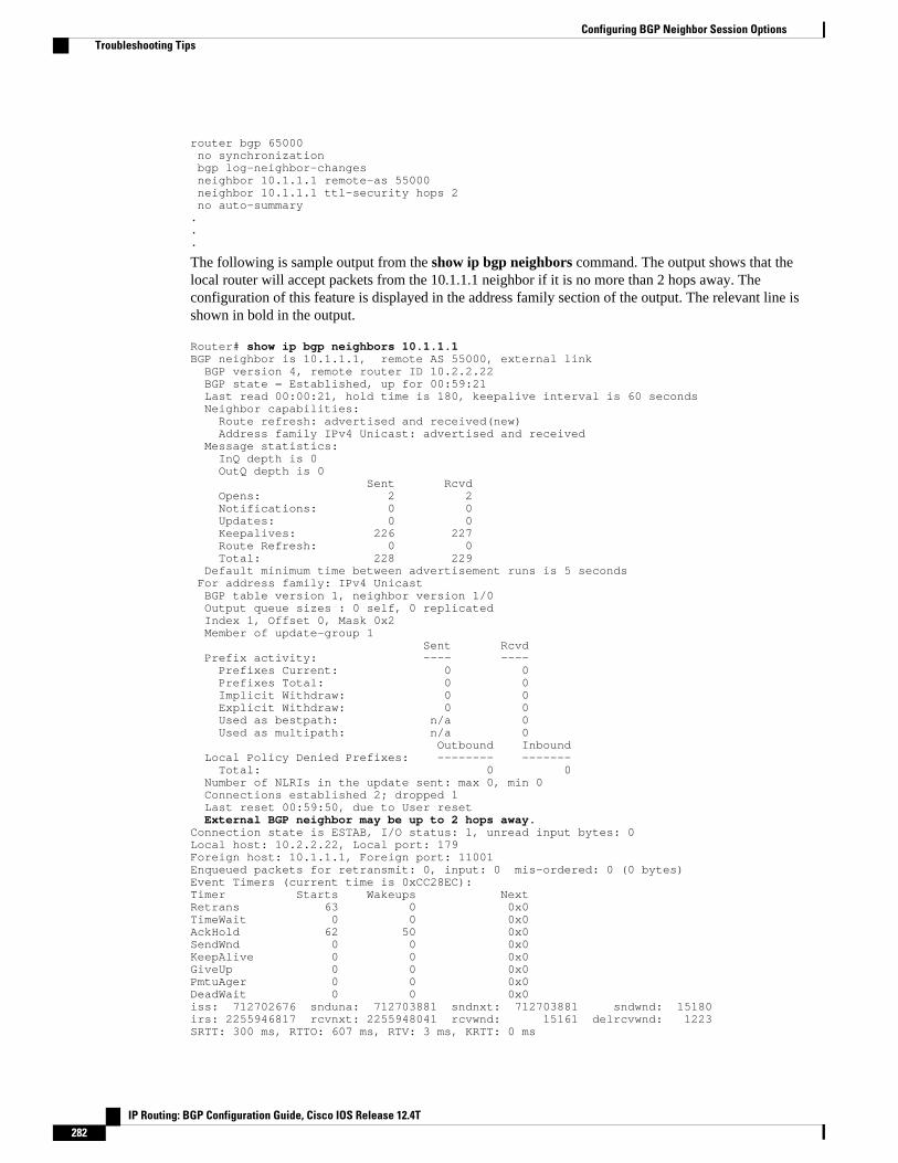
router bgp 65000 no synchronization bgp log-neighbor-changes neighbor 10.1.1.1 remote-as 55000 neighbor 10.1.1.1 ttl-security hops 2 no auto-summary...
The following is sample output from the show ip bgp neighbors command. The output shows that thelocal router will accept packets from the 10.1.1.1 neighbor if it is no more than 2 hops away. Theconfiguration of this feature is displayed in the address family section of the output. The relevant line isshown in bold in the output.
Router# show ip bgp neighbors 10.1.1.1BGP neighbor is 10.1.1.1, remote AS 55000, external link BGP version 4, remote router ID 10.2.2.22 BGP state = Established, up for 00:59:21 Last read 00:00:21, hold time is 180, keepalive interval is 60 seconds Neighbor capabilities: Route refresh: advertised and received(new) Address family IPv4 Unicast: advertised and received Message statistics: InQ depth is 0 OutQ depth is 0 Sent Rcvd Opens: 2 2 Notifications: 0 0 Updates: 0 0 Keepalives: 226 227 Route Refresh: 0 0 Total: 228 229 Default minimum time between advertisement runs is 5 seconds For address family: IPv4 Unicast BGP table version 1, neighbor version 1/0 Output queue sizes : 0 self, 0 replicated Index 1, Offset 0, Mask 0x2 Member of update-group 1 Sent Rcvd Prefix activity: ---- ---- Prefixes Current: 0 0 Prefixes Total: 0 0 Implicit Withdraw: 0 0 Explicit Withdraw: 0 0 Used as bestpath: n/a 0 Used as multipath: n/a 0 Outbound Inbound Local Policy Denied Prefixes: -------- ------- Total: 0 0 Number of NLRIs in the update sent: max 0, min 0 Connections established 2; dropped 1 Last reset 00:59:50, due to User reset External BGP neighbor may be up to 2 hops away.Connection state is ESTAB, I/O status: 1, unread input bytes: 0Local host: 10.2.2.22, Local port: 179Foreign host: 10.1.1.1, Foreign port: 11001Enqueued packets for retransmit: 0, input: 0 mis-ordered: 0 (0 bytes)Event Timers (current time is 0xCC28EC):Timer Starts Wakeups NextRetrans 63 0 0x0TimeWait 0 0 0x0AckHold 62 50 0x0SendWnd 0 0 0x0KeepAlive 0 0 0x0GiveUp 0 0 0x0PmtuAger 0 0 0x0DeadWait 0 0 0x0iss: 712702676 snduna: 712703881 sndnxt: 712703881 sndwnd: 15180irs: 2255946817 rcvnxt: 2255948041 rcvwnd: 15161 delrcvwnd: 1223SRTT: 300 ms, RTTO: 607 ms, RTV: 3 ms, KRTT: 0 ms
Configuring BGP Neighbor Session Options Troubleshooting Tips
IP Routing: BGP Configuration Guide, Cisco IOS Release 12.4T282

minRTT: 0 ms, maxRTT: 300 ms, ACK hold: 200 msFlags: passive open, nagle, gen tcbs Datagrams (max data segment is 1460 bytes):Rcvd: 76 (out of order: 0), with data: 63, total data bytes: 1223Sent: 113 (retransmit: 0, fastretransmit: 0), with data: 62, total data bytes: 4
Configuring BGP Support for TCP Path MTU Discovery per SessionThis section contains the following tasks:
• Disabling TCP Path MTU Discovery Globally for All BGP Sessions, page 283
• Disabling TCP Path MTU Discovery for a Single BGP Neighbor, page 285
• Enabling TCP Path MTU Discovery Globally for All BGP Sessions, page 288
• Enabling TCP Path MTU Discovery for a Single BGP Neighbor, page 290
Disabling TCP Path MTU Discovery Globally for All BGP SessionsPerform this task to disable TCP path MTU discovery for all BGP sessions. TCP path MTU discovery isenabled by default when you configure BGP sessions, but we recommend that you enter the show ip bgpneighbors command to ensure that TCP path MTU discovery is enabled.
This task assumes that you have previously configured BGP neighbors with active TCP connections.
SUMMARY STEPS
1. enable
2. show ip bgp neighbors [ip-address]
3. configure terminal
4. router bgp autonomous-system-number
5. no bgp transport path-mtu-discovery
6. end
7. show ip bgp neighbors [ip-address]
DETAILED STEPS
Command or Action Purpose
Step 1 enable
Example:
Router> enable
Enables privileged EXEC mode.
• Enter your password if prompted.
Configuring BGP Support for TCP Path MTU Discovery per SessionDisabling TCP Path MTU Discovery Globally for All BGP Sessions
IP Routing: BGP Configuration Guide, Cisco IOS Release 12.4T 283

Command or Action Purpose
Step 2 show ip bgp neighbors [ip-address]
Example:
Router# show ip bgp neighbors
(Optional) Displays information about the TCP and BGP connectionsto neighbors.
• Use this command to determine whether BGP neighbors haveTCP path MTU discovery enabled.
Note Only the syntax applicable to this task is used in this example.For more details, see the Cisco IOS IP Routing: BGPCommand Reference.
Step 3 configure terminal
Example:
Router# configure terminal
Enters global configuration mode.
Step 4 router bgp autonomous-system-number
Example:
Router(config)# router bgp 50000
Enters router configuration mode to create or configure a BGP routingprocess.
Step 5 no bgp transport path-mtu-discovery
Example:
Router(config-router)# no bgp transport path-mtu-discovery
Disables TCP path MTU discovery for all BGP sessions.
Step 6 end
Example:
Router(config-router)# end
Exits router configuration mode and returns to privileged EXECmode.
Step 7 show ip bgp neighbors [ip-address]
Example:
Router# show ip bgp neighbors
(Optional) Displays information about the TCP and BGP connectionsto neighbors.
• In this example, the output from this command will not displaythat any neighbors have TCP path MTU enabled.
Note Only the syntax applicable to this task is used in this example.For more details, see the Cisco IOS IP Routing: BGPCommand Reference.
Configuring BGP Neighbor Session Options Disabling TCP Path MTU Discovery Globally for All BGP Sessions
IP Routing: BGP Configuration Guide, Cisco IOS Release 12.4T284

Examples
The following sample output from the show ip bgp neighbors command shows that TCP path MTUdiscovery is enabled for BGP neighbors. Two entries in the output--Transport(tcp) path-mtu-discovery isenabled and path mtu capable--show that TCP path MTU discovery is enabled.
Router# show ip bgp neighborsBGP neighbor is 172.16.1.2, remote AS 45000, internal link BGP version 4, remote router ID 172.16.1.99... For address family: IPv4 Unicast BGP table version 5, neighbor version 5/0... Address tracking is enabled, the RIB does have a route to 172.16.1.2 Address tracking requires at least a /24 route to the peer Connections established 3; dropped 2 Last reset 00:00:35, due to Router ID changed Transport(tcp) path-mtu-discovery is enabled...SRTT: 146 ms, RTTO: 1283 ms, RTV: 1137 ms, KRTT: 0 msminRTT: 8 ms, maxRTT: 300 ms, ACK hold: 200 msFlags: higher precedence, retransmission timeout, nagle, path mtu capable
The following is sample output from the show ip bgp neighbors command after the no bgp transportpath-mtu-discovery command has been entered. Note that the path mtu entries are missing.
Router# show ip bgp neighborsBGP neighbor is 172.16.1.2, remote AS 45000, internal link BGP version 4, remote router ID 172.16.1.99... For address family: IPv4 Unicast BGP table version 5, neighbor version 5/0... Address tracking is enabled, the RIB does have a route to 172.16.1.2 Address tracking requires at least a /24 route to the peer Connections established 3; dropped 2 Last reset 00:00:35, due to Router ID changed...SRTT: 146 ms, RTTO: 1283 ms, RTV: 1137 ms, KRTT: 0 msminRTT: 8 ms, maxRTT: 300 ms, ACK hold: 200 msFlags: higher precedence, retransmission timeout, nagle
Disabling TCP Path MTU Discovery for a Single BGP NeighborPerform this task to establish a peering session with an internal BGP (iBGP) neighbor and then disable TCPpath MTU discovery for the BGP neighbor session. The neighbor transport command can be used inrouter configuration or address family configuration mode.
This task assumes that you know that TCP path MTU discovery is enabled by default for all your BGPneighbors.
Configuring BGP Neighbor Session OptionsDisabling TCP Path MTU Discovery for a Single BGP Neighbor
IP Routing: BGP Configuration Guide, Cisco IOS Release 12.4T 285

SUMMARY STEPS
1. enable
2. configure terminal
3. router bgp autonomous-system-number
4. address-family {ipv4 [mdt | multicast | unicast [vrf vrf-name] | vrf vrf-name] | vpnv4 [unicast]}
5. neighbor {ip-address| peer-group-name} remote-as autonomous-system-number
6. neighbor {ip-address| peer-group-name} activate
7. no neighbor {ip-address| peer-group-name} transport{connection-mode | path-mtu-discovery}
8. end
9. show ip bgp neighbors
DETAILED STEPS
Command or Action Purpose
Step 1 enable
Example:
Router> enable
Enables privileged EXEC mode.
• Enter your password if prompted.
Step 2 configure terminal
Example:
Router# configure terminal
Enters global configuration mode.
Step 3 router bgp autonomous-system-number
Example:
Router(config)# router bgp 45000
Enters router configuration mode for the specified routingprocess.
Step 4 address-family {ipv4 [mdt | multicast | unicast [vrf vrf-name] | vrf vrf-name] | vpnv4 [unicast]}
Example:
Router(config-router)# address-family ipv4 unicast
Enters address family configuration mode to configure BGPpeers to accept address-family-specific configurations.
• The example creates an IPv4 unicast address familysession.
Configuring BGP Neighbor Session Options Disabling TCP Path MTU Discovery for a Single BGP Neighbor
IP Routing: BGP Configuration Guide, Cisco IOS Release 12.4T286

Command or Action Purpose
Step 5 neighbor {ip-address| peer-group-name} remote-asautonomous-system-number
Example:
Router(config-router-af)# neighbor 192.168.1.1 remote-as 45000
Adds the IP address or peer group name of the neighbor inthe specified autonomous system to the IPv4 multiprotocolBGP neighbor table of the local router.
Step 6 neighbor {ip-address| peer-group-name} activate
Example:
Router(config-router-af)# neighbor 172.16.1.1 activate
Activates the neighbor under the IPv4 address family.
Step 7 no neighbor {ip-address| peer-group-name}transport{connection-mode | path-mtu-discovery}
Example:
Router(config-router-af)# no neighbor 172.16.1.1 transport path-mtu-discovery
Disables TCP path MTU discovery for a single BGPneighbor.
• In this example, TCP path MTU discovery is disabledfor the neighbor at 172.16.1.1.
Step 8 end
Example:
Router(config-router-af)# end
Exits address family configuration mode and returns toprivileged EXEC mode.
Step 9 show ip bgp neighbors
Example:
Router# show ip bgp neighbors
(Optional) Displays information about the TCP and BGPconnections to neighbors.
• In this example, the output from this command will notdisplay that the neighbor has TCP path MTU discoveryenabled.
Note Only the syntax applicable to this task is used in thisexample. For more details, see the Cisco IOS IPRouting: BGP Command Reference.
Examples
The following sample output shows that TCP path MTU discovery has been disabled for BGP neighbor172.16.1.1 but that it is still enabled for BGP neighbor 192.168.2.2. Two entries in the output--Transport(tcp) path-mtu-discovery is enabled and path mtu capable--show that TCP path MTU discovery isenabled.
Router# show ip bgp neighborsBGP neighbor is 172.16.1.1, remote AS 45000, internal link BGP version 4, remote router ID 172.17.1.99
Configuring BGP Neighbor Session OptionsDisabling TCP Path MTU Discovery for a Single BGP Neighbor
IP Routing: BGP Configuration Guide, Cisco IOS Release 12.4T 287

.
.
. Address tracking is enabled, the RIB does have a route to 172.16.1.1 Address tracking requires at least a /24 route to the peer Connections established 1; dropped 0 Last reset never...SRTT: 165 ms, RTTO: 1172 ms, RTV: 1007 ms, KRTT: 0 msminRTT: 20 ms, maxRTT: 300 ms, ACK hold: 200 msFlags: higher precedence, retransmission timeout, nagle...BGP neighbor is 192.168.2.2, remote AS 50000, external link BGP version 4, remote router ID 10.2.2.99... For address family: IPv4 Unicast BGP table version 4, neighbor version 4/0... Address tracking is enabled, the RIB does have a route to 192.168.2.2 Address tracking requires at least a /24 route to the peer Connections established 2; dropped 1 Last reset 00:05:11, due to User reset Transport(tcp) path-mtu-discovery is enabled...SRTT: 210 ms, RTTO: 904 ms, RTV: 694 ms, KRTT: 0 msminRTT: 20 ms, maxRTT: 300 ms, ACK hold: 200 msFlags: higher precedence, retransmission timeout, nagle, path mtu capable
Enabling TCP Path MTU Discovery Globally for All BGP SessionsPerform this task to enable TCP path MTU discovery for all BGP sessions. TCP path MTU discovery isenabled by default when you configure BGP sessions, but if the BGP Support for TCP Path MTUDiscovery per Session feature has been disabled, you can use this task to reenable it. To verify that TCPpath MTU discovery is enabled, use the show ip bgp neighbors command.
This task assumes that you have previously configured BGP neighbors with active TCP connections.
SUMMARY STEPS
1. enable
2. configure terminal
3. router bgp autonomous-system-number
4. bgp transport path-mtu-discovery
5. end
6. show ip bgp neighbors
Configuring BGP Neighbor Session Options Enabling TCP Path MTU Discovery Globally for All BGP Sessions
IP Routing: BGP Configuration Guide, Cisco IOS Release 12.4T288

DETAILED STEPS
Command or Action Purpose
Step 1 enable
Example:
Router> enable
Enables privileged EXEC mode.
• Enter your password if prompted.
Step 2 configure terminal
Example:
Router# configure terminal
Enters global configuration mode.
Step 3 router bgp autonomous-system-number
Example:
Router(config)# router bgp 45000
Enters router configuration mode to create or configure a BGProuting process.
Step 4 bgp transport path-mtu-discovery
Example:
Router(config-router)# bgp transport path-mtu-discovery
Enables TCP path MTU discovery for all BGP sessions.
Step 5 end
Example:
Router(config-router)# end
Exits router configuration mode and returns to privileged EXECmode.
Step 6 show ip bgp neighbors
Example:
Router# show ip bgp neighbors
(Optional) Displays information about the TCP and BGPconnections to neighbors.
• In this example, the output from this command will show thatall neighbors have TCP path MTU discovery enabled.
Note Only the syntax applicable to this task is used in thisexample. For more details, see the Cisco IOS IP Routing:BGP Command Reference.
ExamplesThe following sample output from the show ip bgp neighbors command shows that TCP path MTUdiscovery is enabled for BGP neighbors. Two entries in the output--Transport(tcp) path-mtu-discovery isenabled and path mtu capable--show that TCP path MTU discovery is enabled.
Router# show ip bgp neighbors
Configuring BGP Neighbor Session OptionsEnabling TCP Path MTU Discovery Globally for All BGP Sessions
IP Routing: BGP Configuration Guide, Cisco IOS Release 12.4T 289
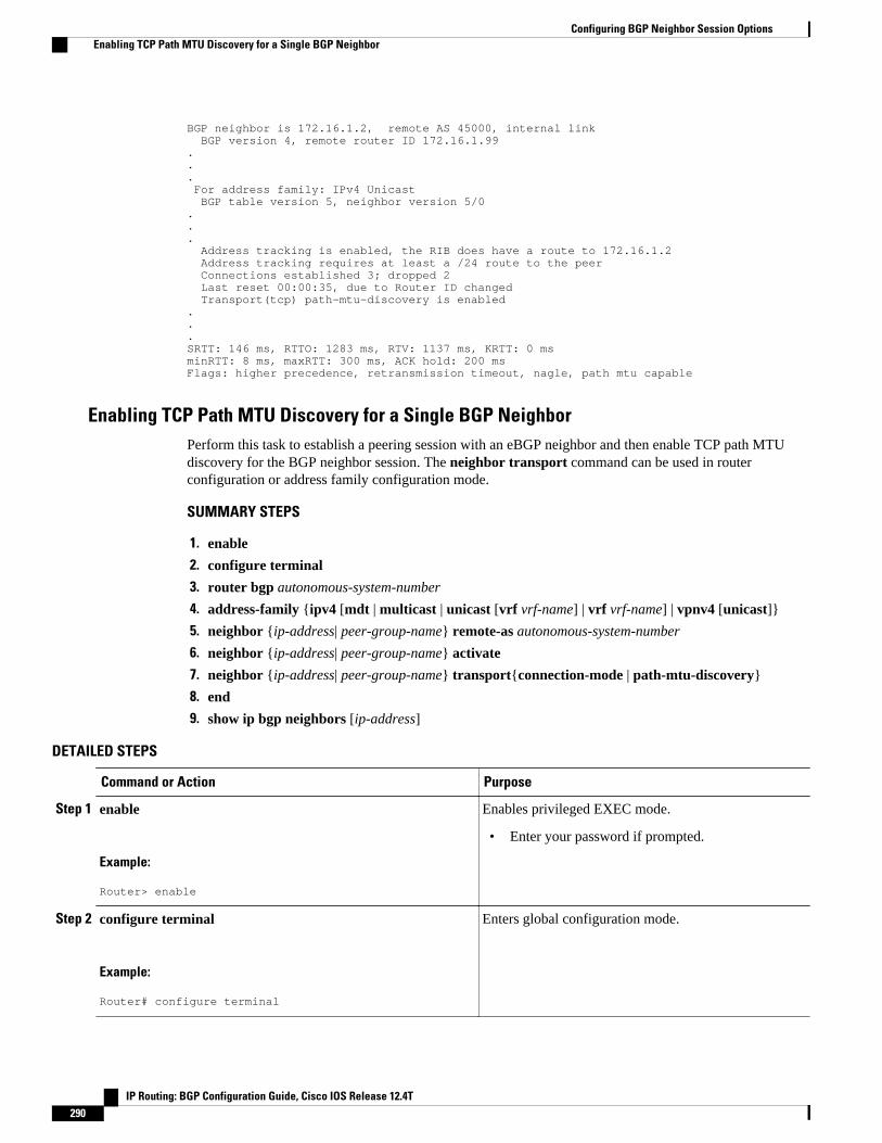
BGP neighbor is 172.16.1.2, remote AS 45000, internal link BGP version 4, remote router ID 172.16.1.99... For address family: IPv4 Unicast BGP table version 5, neighbor version 5/0... Address tracking is enabled, the RIB does have a route to 172.16.1.2 Address tracking requires at least a /24 route to the peer Connections established 3; dropped 2 Last reset 00:00:35, due to Router ID changed Transport(tcp) path-mtu-discovery is enabled...SRTT: 146 ms, RTTO: 1283 ms, RTV: 1137 ms, KRTT: 0 msminRTT: 8 ms, maxRTT: 300 ms, ACK hold: 200 msFlags: higher precedence, retransmission timeout, nagle, path mtu capable
Enabling TCP Path MTU Discovery for a Single BGP NeighborPerform this task to establish a peering session with an eBGP neighbor and then enable TCP path MTUdiscovery for the BGP neighbor session. The neighbor transport command can be used in routerconfiguration or address family configuration mode.
SUMMARY STEPS
1. enable
2. configure terminal
3. router bgp autonomous-system-number
4. address-family {ipv4 [mdt | multicast | unicast [vrf vrf-name] | vrf vrf-name] | vpnv4 [unicast]}
5. neighbor {ip-address| peer-group-name} remote-as autonomous-system-number
6. neighbor {ip-address| peer-group-name} activate
7. neighbor {ip-address| peer-group-name} transport{connection-mode | path-mtu-discovery}
8. end
9. show ip bgp neighbors [ip-address]
DETAILED STEPS
Command or Action Purpose
Step 1 enable
Example:
Router> enable
Enables privileged EXEC mode.
• Enter your password if prompted.
Step 2 configure terminal
Example:
Router# configure terminal
Enters global configuration mode.
Configuring BGP Neighbor Session Options Enabling TCP Path MTU Discovery for a Single BGP Neighbor
IP Routing: BGP Configuration Guide, Cisco IOS Release 12.4T290

Command or Action Purpose
Step 3 router bgp autonomous-system-number
Example:
Router(config)# router bgp 45000
Enters router configuration mode for the specifiedrouting process.
Step 4 address-family {ipv4 [mdt | multicast | unicast [vrf vrf-name]| vrf vrf-name] | vpnv4 [unicast]}
Example:
Router(config-router)# address-family ipv4 unicast
Enters address family configuration mode to configureBGP peers to accept address-family-specificconfigurations.
• The example creates an IPv4 unicast addressfamily session.
Step 5 neighbor {ip-address| peer-group-name} remote-asautonomous-system-number
Example:
Router(config-router-af)# neighbor 192.168.2.2 remote-as 50000
Adds the IP address or peer group name of the neighborin the specified autonomous system to the IPv4multiprotocol BGP neighbor table of the local router.
Step 6 neighbor {ip-address| peer-group-name} activate
Example:
Router(config-router-af)# neighbor 192.168.2.2 activate
Activates the neighbor under the IPv4 address family.
Step 7 neighbor {ip-address| peer-group-name}transport{connection-mode | path-mtu-discovery}
Example:
Router(config-router-af)# neighbor 192.168.2.2 transport path-mtu-discovery
Enables TCP path MTU discovery for a single BGPneighbor.
Step 8 end
Example:
Router(config-router-af)# end
Exits address family configuration mode and returns toprivileged EXEC mode.
Configuring BGP Neighbor Session OptionsEnabling TCP Path MTU Discovery for a Single BGP Neighbor
IP Routing: BGP Configuration Guide, Cisco IOS Release 12.4T 291
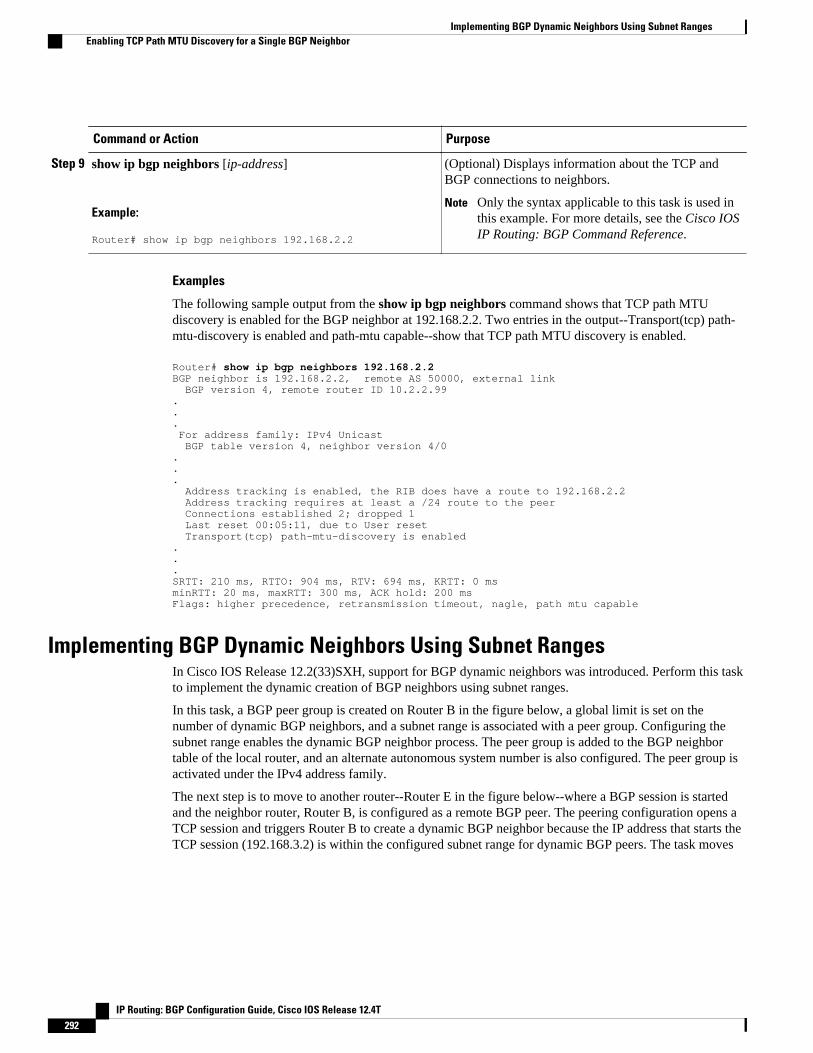
Command or Action Purpose
Step 9 show ip bgp neighbors [ip-address]
Example:
Router# show ip bgp neighbors 192.168.2.2
(Optional) Displays information about the TCP andBGP connections to neighbors.
Note Only the syntax applicable to this task is used inthis example. For more details, see the Cisco IOSIP Routing: BGP Command Reference.
Examples
The following sample output from the show ip bgp neighbors command shows that TCP path MTUdiscovery is enabled for the BGP neighbor at 192.168.2.2. Two entries in the output--Transport(tcp) path-mtu-discovery is enabled and path-mtu capable--show that TCP path MTU discovery is enabled.
Router# show ip bgp neighbors 192.168.2.2BGP neighbor is 192.168.2.2, remote AS 50000, external link BGP version 4, remote router ID 10.2.2.99... For address family: IPv4 Unicast BGP table version 4, neighbor version 4/0... Address tracking is enabled, the RIB does have a route to 192.168.2.2 Address tracking requires at least a /24 route to the peer Connections established 2; dropped 1 Last reset 00:05:11, due to User reset Transport(tcp) path-mtu-discovery is enabled...SRTT: 210 ms, RTTO: 904 ms, RTV: 694 ms, KRTT: 0 msminRTT: 20 ms, maxRTT: 300 ms, ACK hold: 200 msFlags: higher precedence, retransmission timeout, nagle, path mtu capable
Implementing BGP Dynamic Neighbors Using Subnet RangesIn Cisco IOS Release 12.2(33)SXH, support for BGP dynamic neighbors was introduced. Perform this taskto implement the dynamic creation of BGP neighbors using subnet ranges.
In this task, a BGP peer group is created on Router B in the figure below, a global limit is set on thenumber of dynamic BGP neighbors, and a subnet range is associated with a peer group. Configuring thesubnet range enables the dynamic BGP neighbor process. The peer group is added to the BGP neighbortable of the local router, and an alternate autonomous system number is also configured. The peer group isactivated under the IPv4 address family.
The next step is to move to another router--Router E in the figure below--where a BGP session is startedand the neighbor router, Router B, is configured as a remote BGP peer. The peering configuration opens aTCP session and triggers Router B to create a dynamic BGP neighbor because the IP address that starts theTCP session (192.168.3.2) is within the configured subnet range for dynamic BGP peers. The task moves
Implementing BGP Dynamic Neighbors Using Subnet Ranges Enabling TCP Path MTU Discovery for a Single BGP Neighbor
IP Routing: BGP Configuration Guide, Cisco IOS Release 12.4T292
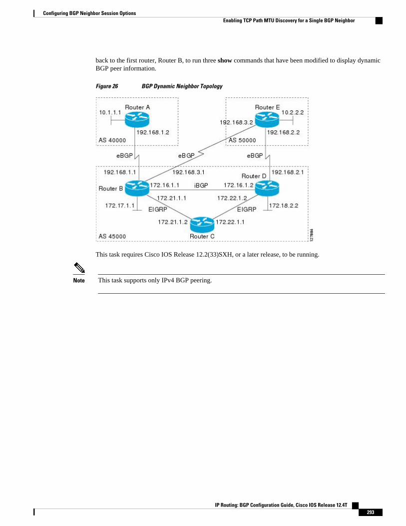
back to the first router, Router B, to run three show commands that have been modified to display dynamicBGP peer information.
Figure 26 BGP Dynamic Neighbor Topology
This task requires Cisco IOS Release 12.2(33)SXH, or a later release, to be running.
Note This task supports only IPv4 BGP peering.
Configuring BGP Neighbor Session OptionsEnabling TCP Path MTU Discovery for a Single BGP Neighbor
IP Routing: BGP Configuration Guide, Cisco IOS Release 12.4T 293

SUMMARY STEPS
1. enable
2. configure terminal
3. router bgp autonomous-system-number
4. bgp log-neighbor-changes
5. neighbor peer-group-name peer-group
6. bgp listen [limit max-number]
7. bgp listen [limit max-number | range network / length peer-group peer-group-name]
8. neighbor {ip-address | ipv6-address | peer-group-name} ebgp-multihop [ ttl]
9. neighbor peer-group-name remote-as autonomous-system-number [alternate-as autonomous-system-number...]
10. address-family ipv4 [mdt | multicast | unicast [vrf vrf-name]]
11. neighbor {ip-address| peer-group-name} activate
12. end
13. Move to another router that has an interface within the subnet range for the BGP peer group configuredin this task.
14. enable
15. configure terminal
16. router bgp autonomous-system-number
17. neighbor {ip-address| peer-group-name} remote-as autonomous-system-number[alternate-as autonomous-system-number...]
18. Return to the first router.
19. show ip bgp summary
20. show ip bgp peer-group [peer-group-name] [summary]
21. show ip bgp neighbors [ip-address]
DETAILED STEPS
Command or Action Purpose
Step 1 enable
Example:
RouterB> enable
Enables privileged EXEC mode.
• Enter your password if prompted.• The configuration is entered on router B.
Step 2 configure terminal
Example:
RouterB# configure terminal
Enters global configuration mode.
Configuring BGP Neighbor Session Options Enabling TCP Path MTU Discovery for a Single BGP Neighbor
IP Routing: BGP Configuration Guide, Cisco IOS Release 12.4T294

Command or Action Purpose
Step 3 router bgp autonomous-system-number
Example:
RouterB(config)# router bgp 45000
Enters router configuration mode for the specified routing process.
Step 4 bgp log-neighbor-changes
Example:
RouterB(config-router)# bgp log-neighbor-changes
(Optional) Enables logging of BGP neighbor status changes (up ordown) and neighbor resets.
• Use this command for troubleshooting network connectivityproblems and measuring network stability. Unexpected neighborresets might indicate high error rates or high packet loss in thenetwork and should be investigated.
Step 5 neighbor peer-group-name peer-group
Example:
RouterB(config-router)# neighbor group192 peer-group
Creates a BGP peer group.
• In this example, a peer group named group192 is created. Thisgroup will be used as a listen range group.
Step 6 bgp listen [limit max-number]
Example:
RouterB(config-router)# bgp listen limit 200
Sets a global limit of BGP dynamic subnet range neighbors.
• Use the optional limit keyword and max-number argument todefine the maximum number of BGP dynamic subnet rangeneighbors that can be created.
Note Only the syntax applicable to this task is used in this example.For the complete syntax, see Step 7.
Step 7 bgp listen [limit max-number | rangenetwork / length peer-group peer-group-name]
Example:
RouterB(config-router)# bgp listen range 192.168.0.0/16 peer-group group192
Associates a subnet range with a BGP peer group and activates the BGPdynamic neighbors feature.
• Use the optional limit keyword and max-number argument todefine the maximum number of BGP dynamic neighbors that canbe created.
• Use the optional range keyword and network / length argument todefine a prefix range to be associated with the specified peergroup.
• In this example, the prefix range 192.168.0.0/16 is associated withthe listen range group named group192.
Step 8 neighbor {ip-address | ipv6-address | peer-group-name} ebgp-multihop [ ttl]
Example:
RouterB(config-router)# neighbor group192 ebgp-multihop 255
Accepts and attempts BGP connections to external peers residing onnetworks that are not directly connected.
Configuring BGP Neighbor Session OptionsEnabling TCP Path MTU Discovery for a Single BGP Neighbor
IP Routing: BGP Configuration Guide, Cisco IOS Release 12.4T 295

Command or Action Purpose
Step 9 neighbor peer-group-name remote-asautonomous-system-number [alternate-as autonomous-system-number...]
Example:
RouterB(config-router)# neighbor group192 remote-as 40000 alternate-as 50000
Adds the IP address or peer group name of the neighbor in the specifiedautonomous system to the IPv4 multiprotocol BGP neighbor table ofthe local router.
• Use the optional alternate-as keyword and autonomous-system-number argument to identify up to five alternate autonomoussystem numbers for listen range neighbors.
• In this example, the peer group named group192 is configured withtwo possible autonomous system numbers.
Note The alternate-as keyword is used only with the listen range peergroups, not with individual BGP neighbors.
Step 10 address-family ipv4 [mdt | multicast |unicast [vrf vrf-name]]
Example:
RouterB(config-router)# address-family ipv4 unicast
Enters address family configuration mode to configure BGP peers toaccept address-family-specific configurations.
Step 11 neighbor {ip-address| peer-group-name}activate
Example:
RouterB(config-router-af)# neighbor group192 activate
Activates the neighbor or listen range peer group for the configuredaddress family.
• In this example, the neighbor 172.16.1.1 is activated for the IPv4address family.
Note Usually BGP peer groups cannot be activated using thiscommand, but the listen range peer groups are a special case.
Step 12 end
Example:
RouterB(config-router-af)# end
Exits address family configuration mode and returns to privilegedEXEC mode.
Step 13 Move to another router that has an interfacewithin the subnet range for the BGP peer groupconfigured in this task.
--
Step 14 enable
Example:
RouterE> enable
Enables privileged EXEC mode.
• Enter your password if prompted.• The configuration is entered on Router E.
Configuring BGP Neighbor Session Options Enabling TCP Path MTU Discovery for a Single BGP Neighbor
IP Routing: BGP Configuration Guide, Cisco IOS Release 12.4T296

Command or Action Purpose
Step 15 configure terminal
Example:
RouterE# configure terminal
Enters global configuration mode.
Step 16 router bgp autonomous-system-number
Example:
RouterE(config)# router bgp 50000
Enters router configuration mode for the specified routing process.
Step 17 neighbor {ip-address| peer-group-name}remote-as autonomous-system-number[alternate-as autonomous-system-number...]
Example:
RouterE(config-router)# neighbor 192.168.3.1 remote-as 45000
Adds the IP address or peer group name of the neighbor in the specifiedautonomous system to the IPv4 multiprotocol BGP neighbor table ofthe local router.
• In this example, the interface (192.168.3.2 in the figure above) atRouter E is with the subnet range set for the BGP listen rangegroup, group192. When TCP opens a session to peer to Router B,Router B creates this peer dynamically.
Step 18 Return to the first router. --
Step 19 show ip bgp summary
Example:
RouterB# show ip bgp summary
(Optional) Displays the BGP path, prefix, and attribute information forall connections to BGP neighbors.
• In this step, the configuration has returned to Router B.
Step 20 show ip bgp peer-group [peer-group-name][summary]
Example:
RouterB# show ip bgp peer-group group192
(Optional) Displays information about BGP peer groups.
Configuring BGP Neighbor Session OptionsEnabling TCP Path MTU Discovery for a Single BGP Neighbor
IP Routing: BGP Configuration Guide, Cisco IOS Release 12.4T 297
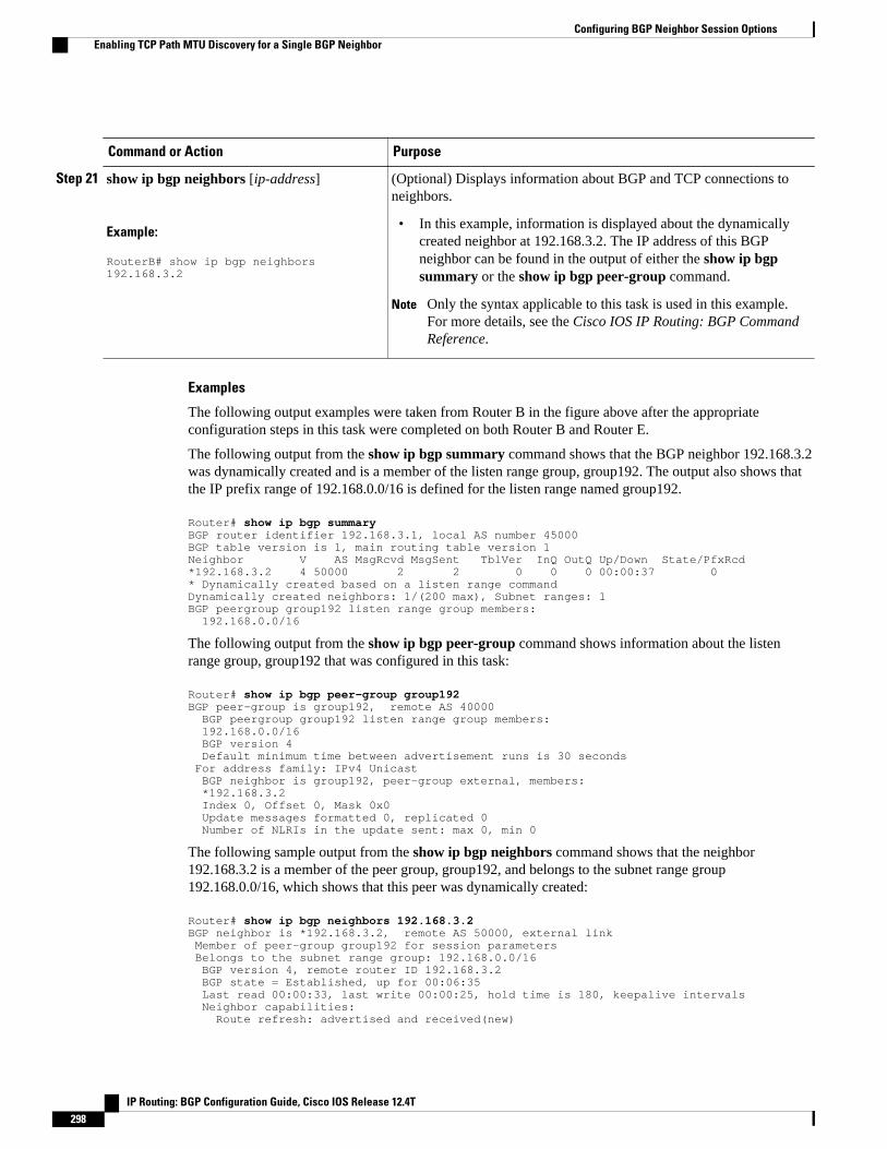
Command or Action Purpose
Step 21 show ip bgp neighbors [ip-address]
Example:
RouterB# show ip bgp neighbors 192.168.3.2
(Optional) Displays information about BGP and TCP connections toneighbors.
• In this example, information is displayed about the dynamicallycreated neighbor at 192.168.3.2. The IP address of this BGPneighbor can be found in the output of either the show ip bgpsummary or the show ip bgp peer-group command.
Note Only the syntax applicable to this task is used in this example.For more details, see the Cisco IOS IP Routing: BGP CommandReference.
Examples
The following output examples were taken from Router B in the figure above after the appropriateconfiguration steps in this task were completed on both Router B and Router E.
The following output from the show ip bgp summary command shows that the BGP neighbor 192.168.3.2was dynamically created and is a member of the listen range group, group192. The output also shows thatthe IP prefix range of 192.168.0.0/16 is defined for the listen range named group192.
Router# show ip bgp summaryBGP router identifier 192.168.3.1, local AS number 45000BGP table version is 1, main routing table version 1Neighbor V AS MsgRcvd MsgSent TblVer InQ OutQ Up/Down State/PfxRcd*192.168.3.2 4 50000 2 2 0 0 0 00:00:37 0* Dynamically created based on a listen range commandDynamically created neighbors: 1/(200 max), Subnet ranges: 1BGP peergroup group192 listen range group members: 192.168.0.0/16
The following output from the show ip bgp peer-group command shows information about the listenrange group, group192 that was configured in this task:
Router# show ip bgp peer-group group192BGP peer-group is group192, remote AS 40000 BGP peergroup group192 listen range group members: 192.168.0.0/16 BGP version 4 Default minimum time between advertisement runs is 30 seconds For address family: IPv4 Unicast BGP neighbor is group192, peer-group external, members: *192.168.3.2 Index 0, Offset 0, Mask 0x0 Update messages formatted 0, replicated 0 Number of NLRIs in the update sent: max 0, min 0
The following sample output from the show ip bgp neighbors command shows that the neighbor192.168.3.2 is a member of the peer group, group192, and belongs to the subnet range group192.168.0.0/16, which shows that this peer was dynamically created:
Router# show ip bgp neighbors 192.168.3.2BGP neighbor is *192.168.3.2, remote AS 50000, external link Member of peer-group group192 for session parameters Belongs to the subnet range group: 192.168.0.0/16 BGP version 4, remote router ID 192.168.3.2 BGP state = Established, up for 00:06:35 Last read 00:00:33, last write 00:00:25, hold time is 180, keepalive intervals Neighbor capabilities: Route refresh: advertised and received(new)
Configuring BGP Neighbor Session Options Enabling TCP Path MTU Discovery for a Single BGP Neighbor
IP Routing: BGP Configuration Guide, Cisco IOS Release 12.4T298

Address family IPv4 Unicast: advertised and received Message statistics: InQ depth is 0 OutQ depth is 0 Sent Rcvd Opens: 1 1 Notifications: 0 0 Updates: 0 0 Keepalives: 7 7 Route Refresh: 0 0 Total: 8 8 Default minimum time between advertisement runs is 30 seconds For address family: IPv4 Unicast BGP table version 1, neighbor version 1/0 Output queue size : 0 Index 1, Offset 0, Mask 0x2 1 update-group member group192 peer-group member...
Configuration Examples for BGP Neighbor Session Options• Example Configuring Fast Session Deactivation for a BGP Neighbor, page 299
• Example Configuring Selective Address Tracking for Fast Session Deactivation, page 300
• Example Configuring BFD for a BGP IPv6 Neighbor, page 300
• Example Restart Session After Maximum Number of Prefixes From Neighbor Reached, page 300
• Examples Configuring Dual-AS Peering for Network Migration, page 300
• Example Configuring the TTL-Security Check, page 302
• Examples Configuring BGP Support for TCP Path MTU Discovery per Session, page 302
• Example Implementing BGP Dynamic Neighbors Using Subnet Ranges, page 303
Example Configuring Fast Session Deactivation for a BGP NeighborIn the following example, the BGP routing process is configured on Router A and Router B to monitor anduse fast peering session deactivation for the neighbor session between the two routers. Although fastpeering session deactivation is not required at both routers in the neighbor session, it will help the BGPnetworks in both autonomous systems to converge faster if the neighbor session is deactivated.
Router A
router bgp 40000 neighbor 192.168.1.1 remote-as 45000 neighbor 192.168.1.1 fall-over end
Router B
router bgp 45000 neighbor 192.168.1.2 remote-as 40000 neighbor 192.168.1.2 fall-over end
Example Configuring Fast Session Deactivation for a BGP NeighborConfiguration Examples for BGP Neighbor Session Options
IP Routing: BGP Configuration Guide, Cisco IOS Release 12.4T 299

Example Configuring Selective Address Tracking for Fast SessionDeactivation
The following example shows how to configure the BGP peering session to be reset if a route with a prefixof /28 or a more specific route to a peer destination is no longer available:
router bgp 45000 neighbor 192.168.1.2 remote-as 40000 neighbor 192.168.1.2 fall-over route-map CHECK-NBR exitip prefix-list FILTER28 seq 5 permit 0.0.0.0/0 ge 28route-map CHECK-NBR permit 10 match ip address prefix-list FILTER28 end
Example Configuring BFD for a BGP IPv6 NeighborThe following example configures FastEthernet interface 0/1 with the IPv6 address 2001:DB8:4:1::1.Bidirectional Forwarding Detection (BFD) is configured for the BGP neighbor at 2001:DB8:5:1::2. BFDwill track forwarding path failure of the BGP neighbor and provide faster reconvergence time for BGP aftera forwarding path failure.
ipv6 unicast-routingipv6 cefinterface fastethernet 0/1 ipv6 address 2001:DB8:4:1::1/64 bfd interval 500 min_rx 500 multiplier 3 no shutdown exitrouter bgp 65000 no bgp default ipv4-unicast address-family ipv6 unicast neighbor 2001:DB8:5:1::2 remote-as 65001 neighbor 2001:DB8:5:1::2 fall-over bfd end
Example Restart Session After Maximum Number of Prefixes From NeighborReached
The following example sets the maximum number of prefixes allowed from the neighbor at 192.168.6.6 to2000 and configures the router to reestablish a peering session after 30 minutes if one has been disabled:
router bgp 101 network 172.16.0.0 neighbor 192.168.6.6 maximum-prefix 2000 restart 30
Examples Configuring Dual-AS Peering for Network MigrationThe following examples show how to configure and verify this feature:
• Example Dual-AS Configuration, page 301
• Example Dual-AS Confederation Configuration, page 301
• Example Replace-AS Configuration, page 302
Example Configuring Selective Address Tracking for Fast Session Deactivation Configuration Examples for BGP Neighbor Session Options
IP Routing: BGP Configuration Guide, Cisco IOS Release 12.4T300

Example Dual-AS ConfigurationThe following examples shows how this feature is used to merge two autonomous systems withoutinterrupting peering arrangements with the customer network. The neighbor local-as command isconfigured to allow Router 1 to maintain peering sessions through autonomous system 40000 andautonomous system 45000. Router 2 is a customer router that runs a BGP routing process in autonomoussystem 50000 and is configured to peer with autonomous-system 45000.
Router 1 in Autonomous System 40000 (Provider Network)
interface Serial3/0 ip address 10.3.3.11 255.255.255.0 ! router bgp 40000 no synchronization bgp router-id 10.0.0.11 neighbor 10.3.3.33 remote-as 50000 neighbor 10.3.3.33 local-as 45000 no-prepend replace-as dual-as
Router 1 in Autonomous System 45000 (Provider Network)
interface Serial3/0 ip address 10.3.3.11 255.255.255.0 ! router bgp 45000 bgp router-id 10.0.0.11 neighbor 10.3.3.33 remote-as 50000
Router 2 in Autonomous System 50000 (Customer Network)
interface Serial3/0 ip address 10.3.3.33 255.255.255.0 ! router bgp 50000 bgp router-id 10.0.0.3 neighbor 10.3.3.11 remote-as 45000
After the transition is complete, the configuration on router 50000 can be updated to peer with autonomoussystem 40000 during a normal maintenance window or during other scheduled downtime:
neighbor 10.3.3.11 remote-as 100
Example Dual-AS Confederation ConfigurationThe following example can be used in place of the Router 1 configuration in the "Example: Dual-ASConfiguration" example . The only difference between these configurations is that Router 1 is configured tobe part of a confederation.
interface Serial3/0/0 ip address 10.3.3.11 255.255.255.0 ! router bgp 65534 no synchronization bgp confederation identifier 100 bgp router-id 10.0.0.11 neighbor 10.3.3.33 remote-as 50000 neighbor 10.3.3.33 local-as 45000 no-prepend replace-as dual-as
Configuring BGP Neighbor Session OptionsExample Dual-AS Configuration
IP Routing: BGP Configuration Guide, Cisco IOS Release 12.4T 301

Example Replace-AS ConfigurationThe following example strips private autonomous system 64512 from outbound routing updates for the10.3.3.33 neighbor and replaces it with autonomous system 50000:
router bgp 64512 neighbor 10.3.3.33 local-as 50000 no-prepend replace-as
Example Configuring the TTL-Security CheckThe example configurations in this section show how to configure the BGP Support for TTL SecurityCheck feature.
The following example uses the trace command to determine the hop count to an eBGP peer. The hopcount number is displayed in the output for each networking device that IP packets traverse to reach thespecified neighbor. In the following example, the hop count for the 10.1.1.1 neighbor is 1.
Router# trace ip 10.1.1.1Type escape sequence to abort.Tracing the route to 10.1.1.1 1 10.1.1.1 0 msec * 0 msec
The following example sets the hop count to 2 for the 10.1.1.1 neighbor. Because the hop-count argumentis set to 2, BGP will accept only IP packets with a TTL count in the header that is equal to or greater than253.
Router(config-router)# neighbor 10.1.1.1 ttl-security hops 2
Examples Configuring BGP Support for TCP Path MTU Discovery perSession
This section contains the following configuration examples:
• Example Disabling TCP Path MTU Discovery Globally for All BGP Sessions, page 302
• Example Disabling TCP Path MTU Discovery for a Single BGP Neighbor, page 302
• Example Enabling TCP Path MTU Discovery Globally for All BGP Sessions, page 303
• Example Enabling TCP Path MTU Discovery for a Single BGP Neighbor, page 303
Example Disabling TCP Path MTU Discovery Globally for All BGP SessionsThe following example shows how to disable TCP path MTU discovery for all BGP neighbor sessions. Usethe show ip bgp neighbors command to verify that TCP path MTU discovery has been disabled.
enableconfigure terminal router bgp 45000 no bgp transport path-mtu-discovery endshow ip bgp neighbors
Example Disabling TCP Path MTU Discovery for a Single BGP Neighbor
Example Configuring the TTL-Security Check Example Replace-AS Configuration
IP Routing: BGP Configuration Guide, Cisco IOS Release 12.4T302
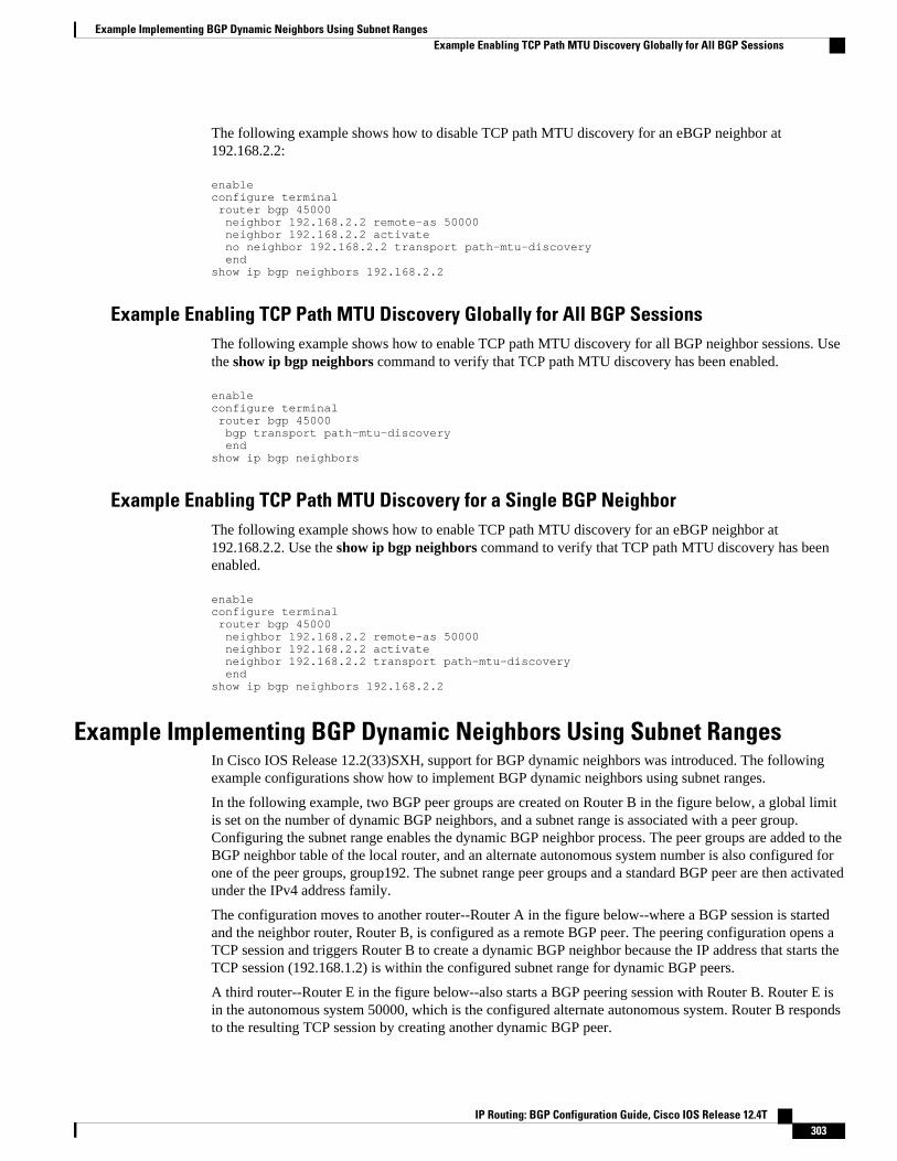
The following example shows how to disable TCP path MTU discovery for an eBGP neighbor at192.168.2.2:
enableconfigure terminal router bgp 45000 neighbor 192.168.2.2 remote-as 50000 neighbor 192.168.2.2 activate no neighbor 192.168.2.2 transport path-mtu-discovery endshow ip bgp neighbors 192.168.2.2
Example Enabling TCP Path MTU Discovery Globally for All BGP SessionsThe following example shows how to enable TCP path MTU discovery for all BGP neighbor sessions. Usethe show ip bgp neighbors command to verify that TCP path MTU discovery has been enabled.
enableconfigure terminal router bgp 45000 bgp transport path-mtu-discovery endshow ip bgp neighbors
Example Enabling TCP Path MTU Discovery for a Single BGP NeighborThe following example shows how to enable TCP path MTU discovery for an eBGP neighbor at192.168.2.2. Use the show ip bgp neighbors command to verify that TCP path MTU discovery has beenenabled.
enableconfigure terminal router bgp 45000 neighbor 192.168.2.2 remote-as 50000 neighbor 192.168.2.2 activate neighbor 192.168.2.2 transport path-mtu-discovery endshow ip bgp neighbors 192.168.2.2
Example Implementing BGP Dynamic Neighbors Using Subnet RangesIn Cisco IOS Release 12.2(33)SXH, support for BGP dynamic neighbors was introduced. The followingexample configurations show how to implement BGP dynamic neighbors using subnet ranges.
In the following example, two BGP peer groups are created on Router B in the figure below, a global limitis set on the number of dynamic BGP neighbors, and a subnet range is associated with a peer group.Configuring the subnet range enables the dynamic BGP neighbor process. The peer groups are added to theBGP neighbor table of the local router, and an alternate autonomous system number is also configured forone of the peer groups, group192. The subnet range peer groups and a standard BGP peer are then activatedunder the IPv4 address family.
The configuration moves to another router--Router A in the figure below--where a BGP session is startedand the neighbor router, Router B, is configured as a remote BGP peer. The peering configuration opens aTCP session and triggers Router B to create a dynamic BGP neighbor because the IP address that starts theTCP session (192.168.1.2) is within the configured subnet range for dynamic BGP peers.
A third router--Router E in the figure below--also starts a BGP peering session with Router B. Router E isin the autonomous system 50000, which is the configured alternate autonomous system. Router B respondsto the resulting TCP session by creating another dynamic BGP peer.
Example Implementing BGP Dynamic Neighbors Using Subnet RangesExample Enabling TCP Path MTU Discovery Globally for All BGP Sessions
IP Routing: BGP Configuration Guide, Cisco IOS Release 12.4T 303

This example concludes with the output of the show ip bgp summary command entered on Router B.
Figure 27 BGP Dynamic Neighbor Topology
Router B
enableconfigure terminalrouter bgp 45000 bgp log-neighbor-changes bgp listen limit 200 bgp listen range 172.21.0.0/16 peer-group group172 bgp listen range 192.168.0.0/16 peer-group group192 neighbor group172 peer-group neighbor group172 remote-as 45000 neighbor group192 peer-group neighbor group192 remote-as 40000 alternate-as 50000 neighbor 172.16.1.2 remote-as 45000 address-family ipv4 unicast neighbor group172 activate neighbor group192 activate neighbor 172.16.1.2 activate end
Router A
enableconfigure terminalrouter bgp 40000 neighbor 192.168.1.1 remote-as 45000 exit
Router E
enableconfigure terminalrouter bgp 50000 neighbor 192.168.3.1 remote-as 45000 exit
Configuring BGP Neighbor Session Options Example Enabling TCP Path MTU Discovery for a Single BGP Neighbor
IP Routing: BGP Configuration Guide, Cisco IOS Release 12.4T304
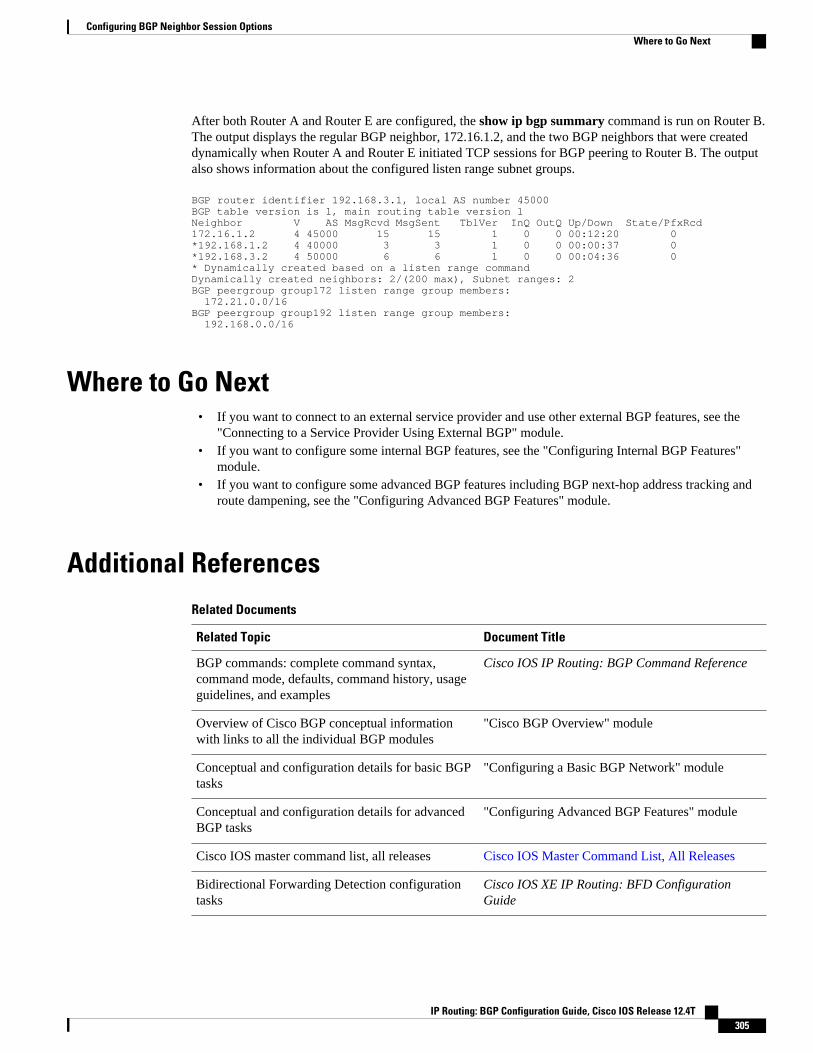
After both Router A and Router E are configured, the show ip bgp summary command is run on Router B.The output displays the regular BGP neighbor, 172.16.1.2, and the two BGP neighbors that were createddynamically when Router A and Router E initiated TCP sessions for BGP peering to Router B. The outputalso shows information about the configured listen range subnet groups.
BGP router identifier 192.168.3.1, local AS number 45000BGP table version is 1, main routing table version 1Neighbor V AS MsgRcvd MsgSent TblVer InQ OutQ Up/Down State/PfxRcd172.16.1.2 4 45000 15 15 1 0 0 00:12:20 0*192.168.1.2 4 40000 3 3 1 0 0 00:00:37 0*192.168.3.2 4 50000 6 6 1 0 0 00:04:36 0* Dynamically created based on a listen range commandDynamically created neighbors: 2/(200 max), Subnet ranges: 2BGP peergroup group172 listen range group members: 172.21.0.0/16 BGP peergroup group192 listen range group members: 192.168.0.0/16
Where to Go Next• If you want to connect to an external service provider and use other external BGP features, see the
"Connecting to a Service Provider Using External BGP" module.• If you want to configure some internal BGP features, see the "Configuring Internal BGP Features"
module.• If you want to configure some advanced BGP features including BGP next-hop address tracking and
route dampening, see the "Configuring Advanced BGP Features" module.
Additional ReferencesRelated Documents
Related Topic Document Title
BGP commands: complete command syntax,command mode, defaults, command history, usageguidelines, and examples
Cisco IOS IP Routing: BGP Command Reference
Overview of Cisco BGP conceptual informationwith links to all the individual BGP modules
"Cisco BGP Overview" module
Conceptual and configuration details for basic BGPtasks
"Configuring a Basic BGP Network" module
Conceptual and configuration details for advancedBGP tasks
"Configuring Advanced BGP Features" module
Cisco IOS master command list, all releases Cisco IOS Master Command List, All Releases
Bidirectional Forwarding Detection configurationtasks
Cisco IOS XE IP Routing: BFD ConfigurationGuide
Configuring BGP Neighbor Session OptionsWhere to Go Next
IP Routing: BGP Configuration Guide, Cisco IOS Release 12.4T 305

Standards
Standard Title
MDT SAFI MDT SAFI
MIBs
MIB MIBs Link
CISCO-BGP4-MIB To locate and download MIBs for selectedplatforms, Cisco IOS XE software releases, andfeature sets, use Cisco MIB Locator found at thefollowing URL:
http://www.cisco.com/go/mibs
RFCs
RFC Title
RFC 1191 Path MTU Discovery
RFC 1771 A Border Gateway Protocol 4 (BGP-4)
RFC 1772 Application of the Border Gateway Protocol in theInternet
RFC 1773 Experience with the BGP Protocol
RFC 1774 BGP-4 Protocol Analysis
RFC 1930 Guidelines for Creation, Selection, andRegistration of an Autonomous System (AS)
RFC 2858 Multiprotocol Extensions for BGP-4
RFC 2918 Route Refresh Capability for BGP-4
Technical Assistance
Description Link
The Cisco Support and Documentation websiteprovides online resources to downloaddocumentation, software, and tools. Use theseresources to install and configure the software andto troubleshoot and resolve technical issues withCisco products and technologies. Access to mosttools on the Cisco Support and Documentationwebsite requires a Cisco.com user ID andpassword.
http://www.cisco.com/cisco/web/support/index.html
Configuring BGP Neighbor Session Options Additional References
IP Routing: BGP Configuration Guide, Cisco IOS Release 12.4T306
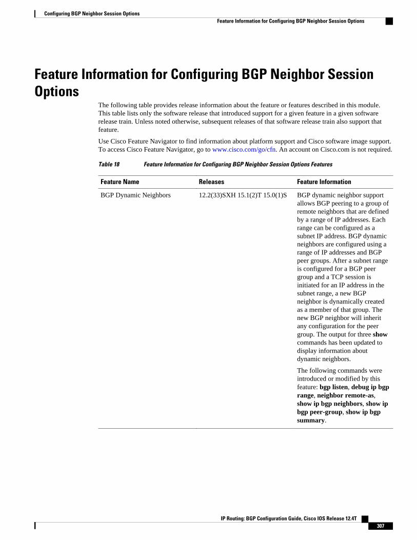
Feature Information for Configuring BGP Neighbor SessionOptions
The following table provides release information about the feature or features described in this module.This table lists only the software release that introduced support for a given feature in a given softwarerelease train. Unless noted otherwise, subsequent releases of that software release train also support thatfeature.
Use Cisco Feature Navigator to find information about platform support and Cisco software image support.To access Cisco Feature Navigator, go to www.cisco.com/go/cfn. An account on Cisco.com is not required.
Table 18 Feature Information for Configuring BGP Neighbor Session Options Features
Feature Name Releases Feature Information
BGP Dynamic Neighbors 12.2(33)SXH 15.1(2)T 15.0(1)S BGP dynamic neighbor supportallows BGP peering to a group ofremote neighbors that are definedby a range of IP addresses. Eachrange can be configured as asubnet IP address. BGP dynamicneighbors are configured using arange of IP addresses and BGPpeer groups. After a subnet rangeis configured for a BGP peergroup and a TCP session isinitiated for an IP address in thesubnet range, a new BGPneighbor is dynamically createdas a member of that group. Thenew BGP neighbor will inheritany configuration for the peergroup. The output for three showcommands has been updated todisplay information aboutdynamic neighbors.
The following commands wereintroduced or modified by thisfeature: bgp listen, debug ip bgprange, neighbor remote-as,show ip bgp neighbors, show ipbgp peer-group, show ip bgpsummary.
Configuring BGP Neighbor Session OptionsFeature Information for Configuring BGP Neighbor Session Options
IP Routing: BGP Configuration Guide, Cisco IOS Release 12.4T 307

Feature Name Releases Feature Information
BGP Restart Session After Max-Prefix Limit
12.0(22)S 12.2(15)T 12.2(18)S15.0(1)S
The BGP Restart Session AfterMax-Prefix Limit featureenhanced the capabilities of theneighbor maximum-prefixcommand with the introduction ofthe restart keyword. Thisenhancement allows the networkoperator to configure the timeinterval at which a peeringsession is reestablished by arouter when the number ofprefixes that have been receivedfrom a peer has exceeded themaximum prefix limit.
The following commands weremodified by this release:neighbor maximum-prefix,show ip bgp neighbors.
BGP Selective Address Tracking 12.4(4)T 12.2(31)SB12.2(33)SRB
The BGP Selective AddressTracking feature introduced theuse of a route map for next-hoproute filtering and fast sessiondeactivation. Selective next-hopfiltering uses a route map toselectively define routes to helpresolve the BGP next hop, or aroute map can be used todetermine if a peering sessionwith a BGP neighbor should bereset when a route to the BGPpeer changes.
The following commands weremodified by this feature: bgpnexthop, neighbor fall-over.
Configuring BGP Neighbor Session Options Feature Information for Configuring BGP Neighbor Session Options
IP Routing: BGP Configuration Guide, Cisco IOS Release 12.4T308
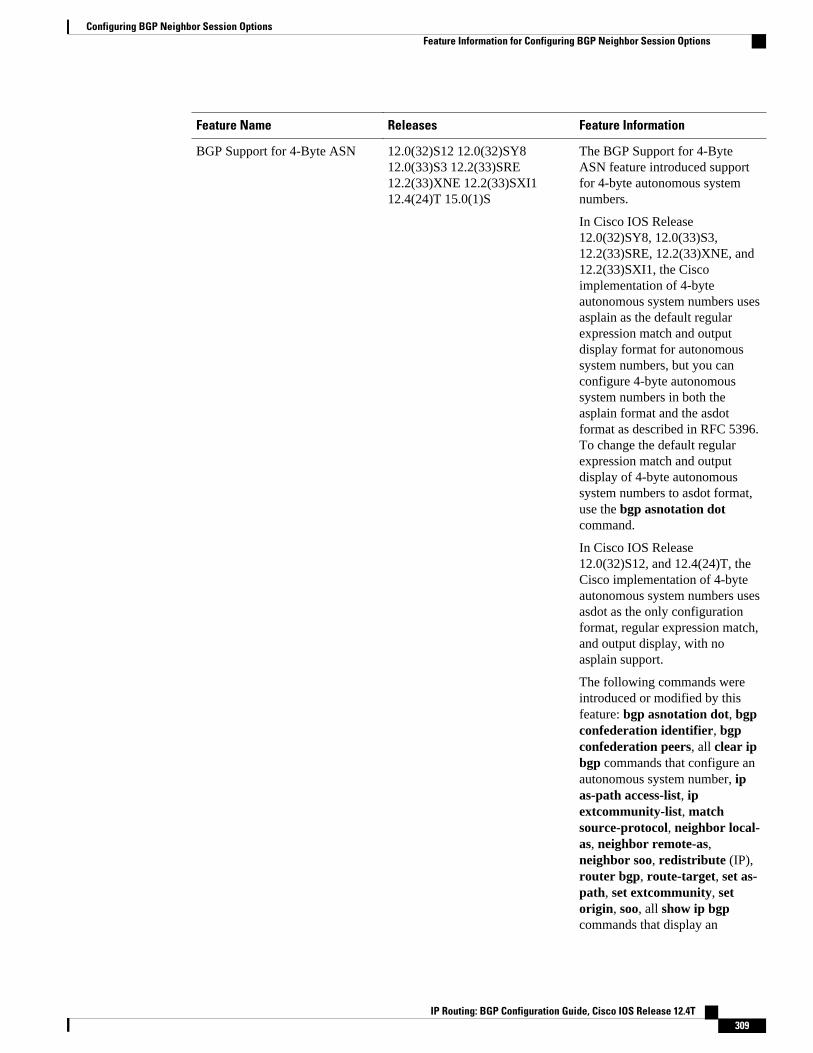
Feature Name Releases Feature Information
BGP Support for 4-Byte ASN 12.0(32)S12 12.0(32)SY812.0(33)S3 12.2(33)SRE12.2(33)XNE 12.2(33)SXI112.4(24)T 15.0(1)S
The BGP Support for 4-ByteASN feature introduced supportfor 4-byte autonomous systemnumbers.
In Cisco IOS Release12.0(32)SY8, 12.0(33)S3,12.2(33)SRE, 12.2(33)XNE, and12.2(33)SXI1, the Ciscoimplementation of 4-byteautonomous system numbers usesasplain as the default regularexpression match and outputdisplay format for autonomoussystem numbers, but you canconfigure 4-byte autonomoussystem numbers in both theasplain format and the asdotformat as described in RFC 5396.To change the default regularexpression match and outputdisplay of 4-byte autonomoussystem numbers to asdot format,use the bgp asnotation dotcommand.
In Cisco IOS Release12.0(32)S12, and 12.4(24)T, theCisco implementation of 4-byteautonomous system numbers usesasdot as the only configurationformat, regular expression match,and output display, with noasplain support.
The following commands wereintroduced or modified by thisfeature: bgp asnotation dot, bgpconfederation identifier, bgpconfederation peers, all clear ipbgp commands that configure anautonomous system number, ipas-path access-list, ipextcommunity-list, matchsource-protocol, neighbor local-as, neighbor remote-as,neighbor soo, redistribute (IP),router bgp, route-target, set as-path, set extcommunity, setorigin, soo, all show ip bgpcommands that display an
Configuring BGP Neighbor Session OptionsFeature Information for Configuring BGP Neighbor Session Options
IP Routing: BGP Configuration Guide, Cisco IOS Release 12.4T 309

Feature Name Releases Feature Information
autonomous system number, andshow ip extcommunity-list.
BGP Support for Dual ASConfiguration for Network ASMigrations
12.0(27)S 12.2(25)S 12.3(11)T12.2(33)SRA 12.2(33)SXH15.0(1)S
The BGP Support for Dual ASConfiguration for Network ASMigrations feature extended thefunctionality of the BGP Local-AS feature by providingadditional autonomous systempath customization configurationoptions. The configuration of thisfeature is transparent to customerpeering sessions, allowing theprovider to merge twoautonomous systems withoutinterrupting customer peeringarrangements. Customer peeringsessions can later be updatedduring a maintenance window orduring other scheduled downtime.
The following command wasmodified by this feature:neighbor local-as.
BGP Support for Fast PeeringSession Deactivation
12.0(29)S 12.3(14)T12.2(33)SRA 12.2(31)SB12.2(33)SXH 15.0(1)S
The BGP Support for FastPeering Session Deactivationfeature introduced an event-driven notification system thatallows a Border GatewayProtocol (BGP) process tomonitor BGP peering sessions ona per-neighbor basis. This featureimproves the response time ofBGP to adjacency changes byallowing BGP to detect anadjacency change and deactivatethe terminated session in betweenstandard BGP scanning intervals.Enabling this feature improvesoverall BGP convergence.
The following command wasmodified by this feature:neighbor fall-over.
Configuring BGP Neighbor Session Options Feature Information for Configuring BGP Neighbor Session Options
IP Routing: BGP Configuration Guide, Cisco IOS Release 12.4T310

Feature Name Releases Feature Information
BGP Support for TCP Path MTUDiscovery per Session
12.2(33)SRA 12.2(31)SB12.2(33)SXH 12.4(20)T 15.0(1)S
BGP support for TCP pathmaximum transmission unit(MTU) discovery introduced theability for BGP to automaticallydiscover the best TCP path MTUfor each BGP session. The TCPpath MTU is enabled by defaultfor all BGP neighbor sessions,but you can disable, andsubsequently enable, the TCPpath MTU globally for all BGPsessions or for an individual BGPneighbor session.
The following commands wereintroduced or modified by thisfeature: bgp transport, neighbortransport, show ip bgpneighbors.
BGP Support for TTL SecurityCheck
12.0(27)S 12.3(7)T 12.2(25)S12.2(18)SXE 15.0(1)S
The BGP Support for TTLSecurity Check feature introduceda lightweight security mechanismto protect external BorderGateway Protocol (eBGP)peering sessions from CPUutilization-based attacks usingforged IP packets. Enabling thisfeature prevents attempts tohijack the eBGP peering sessionby a host on a network segmentthat is not part of either BGPnetwork or by a host on a networksegment that is not between theeBGP peers.
The following commands wereintroduced or modified by thisfeature: neighbor ttl-security,show ip bgp neighbors.
BGP IPv6 Client for Single-HopBFD
15.1(2)S Bidirectional ForwardingDetection (BFD) can be used totrack fast forwarding path failureof BGP neighbors that use anIPv6 address.
The following command wasmodified by this feature:neighbor fall-over.
Configuring BGP Neighbor Session OptionsFeature Information for Configuring BGP Neighbor Session Options
IP Routing: BGP Configuration Guide, Cisco IOS Release 12.4T 311

Cisco and the Cisco logo are trademarks or registered trademarks of Cisco and/or its affiliates in the U.S.and other countries. To view a list of Cisco trademarks, go to this URL: www.cisco.com/go/trademarks.Third-party trademarks mentioned are the property of their respective owners. The use of the word partnerdoes not imply a partnership relationship between Cisco and any other company. (1110R)
Any Internet Protocol (IP) addresses and phone numbers used in this document are not intended to beactual addresses and phone numbers. Any examples, command display output, network topology diagrams,and other figures included in the document are shown for illustrative purposes only. Any use of actual IPaddresses or phone numbers in illustrative content is unintentional and coincidental.
Configuring BGP Neighbor Session Options
IP Routing: BGP Configuration Guide, Cisco IOS Release 12.4T312
Configuring Advanced BGP Features
This module describes configuration tasks for various advanced Border Gateway Protocol (BGP) features.BGP is an interdomain routing protocol designed to provide loop-free routing between organizations. Thismodule contains tasks to configure BGP next-hop address tracking, BGP Nonstop Forwarding (NSF)awareness using the BGP graceful restart capability, route dampening, Bidirectional Forwarding Detection(BFD) support for BGP, BGP MIB support and BGP support for Multi-Topology Routing (MTR).
• Finding Feature Information, page 313• Prerequisites for Configuring Advanced BGP Features, page 313• Restrictions for Configuring Advanced BGP Features, page 313• Information About Configuring Advanced BGP Features, page 314• How to Configure Advanced BGP Features, page 324• Where to Go Next, page 363• Additional References, page 363• Feature Information for Configuring Advanced BGP Features, page 364
Finding Feature InformationYour software release may not support all the features documented in this module. For the latest featureinformation and caveats, see the release notes for your platform and software release. To find informationabout the features documented in this module, and to see a list of the releases in which each feature issupported, see the Feature Information Table at the end of this document.
Use Cisco Feature Navigator to find information about platform support and Cisco software image support.To access Cisco Feature Navigator, go to www.cisco.com/go/cfn. An account on Cisco.com is not required.
Prerequisites for Configuring Advanced BGP FeaturesBefore configuring advanced BGP features you should be familiar with the "Cisco BGP Overview" moduleand the "Configuring a Basic BGP Network" module.
Restrictions for Configuring Advanced BGP Features• A router that runs Cisco IOS software can be configured to run only one BGP routing process and to
be a member of only one BGP autonomous system. However, a BGP routing process and autonomoussystem can support multiple address family configurations.
• Multicast BGP peer support is not available in Cisco IOS software after Release 12.2(33)SRA.
IP Routing: BGP Configuration Guide, Cisco IOS Release 12.4T 313

Information About Configuring Advanced BGP Features• BGP Version 4, page 314
• BGP Support for Next-Hop Address Tracking, page 314
• BGP Nonstop Forwarding Awareness, page 315
• BGP Route Dampening, page 319
• BFD for BGP, page 320
• BGP MIB Support, page 320
• BGP Support for MTR, page 322
BGP Version 4Border Gateway Protocol (BGP) is an interdomain routing protocol designed to provide loop-free routingbetween separate routing domains that contain independent routing policies (autonomous systems). TheCisco IOS software implementation of BGP version 4 includes multiprotocol extensions to allow BGP tocarry routing information for IP multicast routes and multiple Layer 3 protocol address families includingIP Version 4 (IPv4), IP Version 6 (IPv6), Virtual Private Networks version 4 (VPNv4), and ConnectionlessNetwork Services (CLNS). For more details about configuring a basic BGP network, see the "Configuringa Basic BGP Network" module.
BGP is mainly used to connect a local network to an external network to gain access to the Internet or toconnect to other organizations. When connecting to an external organization, external BGP (eBGP) peeringsessions are created. For more details about connecting to external BGP peers, see the "Connecting to aService Provider Using External BGP" module.
Although BGP is referred to as an exterior gateway protocol (EGP) many networks within an organizationare becoming so complex that BGP can be used to simplify the internal network used within theorganization. BGP peers within the same organization exchange routing information through internal BGP(iBGP) peering sessions. For more details about internal BGP peers, see the "Configuring Internal BGPFeatures" chapter of the Cisco IOS IP Routing Configuration Guide.
Note BGP requires more configuration than other routing protocols and the effects of any configuration changesmust be fully understood. Incorrect configuration can create routing loops and negatively impact normalnetwork operation.
BGP Support for Next-Hop Address TrackingTo configure BGP next-hop address tracking you should understand the following concepts:
• BGP Next-Hop Address Tracking, page 314
• Default BGP Scanner Behavior, page 315
• Selective BGP Next-Hop Route Filtering, page 315
• BGP Next_Hop Attribute, page 315
BGP Next-Hop Address Tracking
BGP Version 4 Information About Configuring Advanced BGP Features
IP Routing: BGP Configuration Guide, Cisco IOS Release 12.4T314

The BGP next-hop address tracking feature is enabled by default when a supporting Cisco software imageis installed. BGP next-hop address tracking is event driven. BGP prefixes are automatically tracked aspeering sessions are established. Next-hop changes are rapidly reported to the BGP routing process as theyare updated in the RIB. This optimization improves overall BGP convergence by reducing the responsetime to next-hop changes for routes installed in the RIB. When a best-path calculation is run in betweenBGP scanner cycles, only next-hop changes are tracked and processed.
Default BGP Scanner BehaviorBGP monitors the next hop of installed routes to verify next-hop reachability and to select, install, andvalidate the BGP best path. By default, the BGP scanner is used to poll the RIB for this information every60 seconds. During the 60 second time period between scan cycles, Interior Gateway Protocol (IGP)instability or other network failures can cause black holes and routing loops to temporarily form.
Selective BGP Next-Hop Route FilteringIn Cisco IOS Release 12.4(4)T, 12.2(33)SRB, and later releases, BGP selective next-hop route filtering wasimplemented as part of the BGP Selective Address Tracking feature to support BGP next-hop addresstracking. Selective next-hop route filtering uses a route map to selectively define routes to help resolve theBGP next hop.
The ability to use a route map with the bgp nexthopcommand allows the configuration of the length of aprefix that applies to the BGP Next_Hop attribute. The route map is used during the BGP bestpathcalculation and is applied to the route in the routing table that covers the next-hop attribute for BGPprefixes. If the next-hop route fails the route map evaluation, the next-hop route is marked as unreachable.This command is per address family, so different route maps can be applied for next-hop routes in differentaddress families.
Note The route-map and map-name keyword-argument pair in the bgp nexthop command are not supported inCisco IOS Release 15.0(1)SY.
Note Only match ip address and match source-protocol commands are supported in the route map. No setcommands or other match commands are supported.
BGP Next_Hop AttributeThe Next_Hop attribute identifies the next-hop IP address to be used as the BGP next hop to thedestination. The router makes a recursive lookup to find the BGP next hop in the routing table. In externalBGP (eBGP), the next hop is the IP address of the peer that sent the update. Internal BGP (iBGP) sets thenext-hop address to the IP address of the peer that advertised the prefix for routes that originate internally.When any routes to iBGP that are learned from eBGP are advertised, the Next_Hop attribute is unchanged.
A BGP next-hop IP address must be reachable in order for the router to use a BGP route. Reachabilityinformation is usually provided by the IGP, and changes in the IGP can influence the forwarding of thenext-hop address over a network backbone.
BGP Nonstop Forwarding AwarenessTo configure BGP Nonstop Forwarding (NSF) awareness you should understand the following concepts:
BGP Nonstop Forwarding AwarenessDefault BGP Scanner Behavior
IP Routing: BGP Configuration Guide, Cisco IOS Release 12.4T 315

• Cisco NSF Routing and Forwarding Operation, page 316
• Cisco Express Forwarding for NSF, page 316
• BGP Graceful Restart for NSF, page 317
• BGP NSF Awareness, page 317
• BGP Graceful Restart per Neighbor, page 318
• BGP Peer Session Templates, page 318
Cisco NSF Routing and Forwarding OperationCisco NSF is supported by the BGP, EIGRP, OSPF, and IS-IS protocols for routing and by Cisco ExpressForwarding (CEF) for forwarding. Of the routing protocols, BGP, EIGRP, OSPF, and IS-IS have beenenhanced with NSF-capability and awareness, which means that routers running these protocols can detecta switchover and take the necessary actions to continue forwarding network traffic and to recover routeinformation from the peer devices.
In this document, a networking device is said to be NSF-aware if it is running NSF-compatible software. Adevice is said to be NSF-capable if it has been configured to support NSF; therefore, it would rebuildrouting information from NSF-aware or NSF-capable neighbors.
Each protocol depends on CEF to continue forwarding packets during switchover while the routingprotocols rebuild the Routing Information Base (RIB) tables. Once the routing protocols have converged,CEF updates the FIB table and removes stale route entries. CEF then updates the line cards with the newFIB information.
Note Currently, EIGRP supports only NSF awareness.
Cisco Express Forwarding for NSFA key element of NSF is packet forwarding. In a Cisco networking device, packet forwarding is providedby CEF. CEF maintains the FIB and uses the FIB information that was current at the time of the switchoverto continue forwarding packets during a switchover. This feature reduces traffic interruption during theswitchover.
During normal NSF operation, CEF on the active RP synchronizes its current FIB and adjacency databaseswith the FIB and adjacency databases on the standby RP. Upon switchover of the active RP, the standbyRP initially has FIB and adjacency databases that are mirror images of those that were current on the activeRP. For platforms with intelligent line cards, the line cards will maintain the current forwardinginformation over a switchover; for platforms with forwarding engines, CEF will keep the forwardingengine on the standby RP current with changes that are sent to it by CEF on the active RP. In this way, theline cards or forwarding engines will be able to continue forwarding after a switchover as soon as theinterfaces and a data path are available.
As the routing protocols start to repopulate the RIB on a prefix-by-prefix basis, the updates in turn causeprefix-by-prefix updates for CEF, which it uses to update the FIB and adjacency databases. Existing andnew entries will receive the new version ("epoch") number, indicating that they have been refreshed. Theforwarding information is updated on the line cards or forwarding engine during convergence. The RPsignals when the RIB has converged. The software removes all FIB and adjacency entries that have anepoch older than the current switchover epoch. The FIB now represents the newest routing protocolforwarding information
Configuring Advanced BGP Features Cisco NSF Routing and Forwarding Operation
IP Routing: BGP Configuration Guide, Cisco IOS Release 12.4T316
The routing protocols run only on the active RP, and they receive routing updates from their neighborrouters. Routing protocols do not run on the standby RP. Following a switchover, the routing protocolsrequest that the NSF-aware neighbor devices send state information to help rebuild the routing tables.
Note For NSF operation, the routing protocols depend on CEF to continue forwarding packets while the routingprotocols rebuild the routing information.
BGP Graceful Restart for NSFWhen an NSF-capable router begins a BGP session with a BGP peer, it sends an OPEN message to thepeer. Included in the message is a declaration that the NSF-capable or NSF-aware router has "gracefulrestart capability." Graceful restart is the mechanism by which BGP routing peers avoid a routing flapfollowing a switchover. If the BGP peer has received this capability, it is aware that the device sending themessage is NSF-capable. Both the NSF-capable router and its BGP peer(s) (NSF-aware peers) need toexchange the graceful restart capability in their OPEN messages, at the time of session establishment. Ifboth the peers do not exchange the graceful restart capability, the session will not be graceful restartcapable.
If the BGP session is lost during the RP switchover, the NSF-aware BGP peer marks all the routesassociated with the NSF-capable router as stale; however, it continues to use these routes to makeforwarding decisions for a set period of time. This functionality means that no packets are lost while thenewly active RP is waiting for convergence of the routing information with the BGP peers.
After an RP switchover occurs, the NSF-capable router reestablishes the session with the BGP peer. Inestablishing the new session, it sends a new graceful restart message that identifies the NSF-capable routeras having restarted.
At this point, the routing information is exchanged between the two BGP peers. Once this exchange iscomplete, the NSF-capable device uses the routing information to update the RIB and the FIB with the newforwarding information. The NSF-aware device uses the network information to remove stale routes fromits BGP table. Following that, the BGP protocol is fully converged.
If a BGP peer does not support the graceful restart capability, it will ignore the graceful restart capability inan OPEN message but will establish a BGP session with the NSF-capable device. This functionality willallow interoperability with non-NSF-aware BGP peers (and without NSF functionality), but the BGPsession with non-NSF-aware BGP peers will not be graceful restart capable.
BGP NSF AwarenessBGP support for NSF requires that neighbor routers are NSF-aware or NSF-capable. NSF awareness inBGP is also enabled by the graceful restart mechanism. A router that is NSF-aware functions like a routerthat is NSF-capable with one exception: an NSF-aware router is incapable of performing an SSO operation.However, a router that is NSF-aware is capable of maintaining a peering relationship with a NSF-capableneighbor during a NSF SSO operation, as well as holding routes for this neighbor during the SSOoperation.
The BGP Nonstop Forwarding Awareness feature provides an NSF-aware router with the capability todetect a neighbor that is undergoing an SSO operation, maintain the peering session with this neighbor,retain known routes, and continue to forward packets for these routes. The deployment of BGP NSFawareness can minimize the affects of route-processor (RP) failure conditions and improve the overallnetwork stability by reducing the amount of resources that are normally required for reestablishing peeringwith a failed router.
Configuring Advanced BGP FeaturesBGP Graceful Restart for NSF
IP Routing: BGP Configuration Guide, Cisco IOS Release 12.4T 317

NSF awareness for BGP is not enabled by default. The bgp graceful-restart command is used to globallyenable NSF awareness on a router that is running BGP. NSF-aware operations are also transparent to thenetwork operator and BGP peers that do not support NSF capabilities.
Note NSF awareness is enabled automatically in supported software images for Interior Gateway Protocols, suchas EIGRP, IS-IS, and OSPF. In BGP, global NSF awareness is not enabled automatically and must bestarted by issuing the bgp graceful-restart command in router configuration mode.
BGP Graceful Restart per NeighborIn Cisco IOS Releases 12.2(33)SRC, 12.2(33)SB (on platforms including the Cisco 10000 series routers),15.0(1)M, and later releases, the ability to enable or disable BGP graceful restart for every individual BGPneighbor was introduced. Three new methods of configuring BGP graceful restart for BGP peers, inaddition to the existing global BGP graceful restart configuration, are now available. Graceful restart can beenabled or disabled for a BGP peer or a BGP peer group using the neighbor ha-mode graceful-restartcommand, or a BGP peer can inherit a graceful restart configuration from a BGP peer-session templateusing the ha-mode graceful-restartcommand.
Although BGP graceful restart is disabled by default, the existing global command enables graceful restartfor all BGP neighbors regardless of their capabilities. The ability to enable or disable BGP graceful restartfor individual BGP neighbors provides a greater level of control for a network administrator.
When the BGP graceful restart capability is configured for an individual neighbor, each method ofconfiguring graceful restart has the same priority, and the last configuration instance is applied to theneighbor. For example, if global graceful restart is enabled for all BGP neighbors but an individualneighbor is subsequently configured as a member of a peer group for which the graceful restart is disabled,graceful restart is disabled for that neighbor.
The configuration of the restart and stale-path timers is available only with the global bgp graceful-restartcommand, but the default values are set when the neighbor ha-mode graceful-restartor ha-modegraceful-restart commands are configured. The default values are optimal for most network deployments,and these values should be adjusted only by an experienced network operator.
BGP Peer Session TemplatesPeer session templates are used to group and apply the configuration of general BGP session commands togroups of neighbors that share session configuration elements. General session commands that are commonfor neighbors that are configured in different address families can be configured within the same peersession template. Peer session templates are created and configured in peer session configuration mode.Only general session commands can be configured in a peer session template.
General session commands can be configured once in a peer session template and then applied to manyneighbors through the direct application of a peer session template or through indirect inheritance from apeer session template. The configuration of peer session templates simplifies the configuration of generalsession commands that are commonly applied to all neighbors within an autonomous system.
Peer session templates support direct and indirect inheritance. A BGP neighbor can be configured with onlyone peer session template at a time, and that peer session template can contain only one indirectly inheritedpeer session template. A BGP neighbor can directly inherit only one session template and can indirectlyinherit up to seven additional peer session templates.
Configuring Advanced BGP Features BGP Graceful Restart per Neighbor
IP Routing: BGP Configuration Guide, Cisco IOS Release 12.4T318

Peer session templates support inheritance. A directly applied peer session template can directly orindirectly inherit configurations from up to seven peer session templates. So, a total of eight peer sessiontemplates can be applied to a neighbor or neighbor group.
Peer session templates support only general session commands. BGP policy configuration commands thatare configured only for a specific address family or NLRI configuration mode are configured with peerpolicy templates.
For more details about BGP peer session templates, see the "Configuring a Basic BGP Network" module.
To use a BGP peer session template to enable or disable BGP graceful restart, see the section "Enablingand Disabling BGP Graceful Restart Using BGP Peer Session Templates".
BGP Route DampeningRoute dampening is a BGP feature designed to minimize the propagation of flapping routes across aninternetwork. A route is considered to be flapping when its availability alternates repeatedly.
For example, consider a network with three BGP autonomous systems: autonomous system 1, autonomoussystem 2, and autonomous system 3. Suppose the route to network A in autonomous system 1 flaps (itbecomes unavailable). Under circumstances without route dampening, the eBGP neighbor of autonomoussystem 1 to autonomous system 2 sends a withdraw message to autonomous system 2. The border router inautonomous system 2, in turn, propagates the withdraw message to autonomous system 3. When the routeto network A reappears, autonomous system 1 sends an advertisement message to autonomous system 2,which sends it to autonomous system 3. If the route to network A repeatedly becomes unavailable, thenavailable, many withdrawal and advertisement messages are sent. This is a problem in an internetworkconnected to the Internet because a route flap in the Internet backbone usually involves many routes.
Note No penalty is applied to a BGP peer reset when route dampening is enabled. Although the reset withdrawsthe route, no penalty is applied in this instance, even if route flap dampening is enabled.
Minimizing Flapping
The route dampening feature minimizes the flapping problem as follows. Suppose again that the route tonetwork A flaps. The router in autonomous system 2 (where route dampening is enabled) assigns networkA a penalty of 1000 and moves it to history state. The router in autonomous system 2 continues to advertisethe status of the route to neighbors. The penalties are cumulative. When the route flaps so often that thepenalty exceeds a configurable suppress limit, the router stops advertising the route to network A,regardless of how many times it flaps. Thus, the route is dampened.
The penalty placed on network A is decayed until the reuse limit is reached, upon which the route is onceagain advertised. At half of the reuse limit, the dampening information for the route to network A isremoved.
Understanding Route Dampening Terms
The following terms are used when describing route dampening:
• Flap--A route whose availability alternates repeatedly.• History state--After a route flaps once, it is assigned a penalty and put into history state, meaning the
router does not have the best path, based on historical information.• Penalty--Each time a route flaps, the router configured for route dampening in another autonomous
system assigns the route a penalty of 1000. Penalties are cumulative. The penalty for the route is stored
BGP Route DampeningBGP Peer Session Templates
IP Routing: BGP Configuration Guide, Cisco IOS Release 12.4T 319
in the BGP routing table until the penalty exceeds the suppress limit. At that point, the route statechanges from history to damp.
• Damp state--In this state, the route has flapped so often that the router will not advertise this route toBGP neighbors.
• Suppress limit--A route is suppressed when its penalty exceeds this limit. The default value is 2000.• Half-life--Once the route has been assigned a penalty, the penalty is decreased by half after the half-
life period (which is 15 minutes by default). The process of reducing the penalty happens every 5seconds.
• Reuse limit--As the penalty for a flapping route decreases and falls below this reuse limit, the route isunsuppressed. That is, the route is added back to the BGP table and once again used for forwarding.The default reuse limit is 750. The process of unsuppressing routes occurs at 10-second increments.Every 10 seconds, the router finds out which routes are now unsuppressed and advertises them to theworld.
• Maximum suppress limit--This value is the maximum amount of time a route can be suppressed. Thedefault value is four times the half-life.
The routes external to an autonomous system learned via iBGP are not dampened. This policy prevent theiBGP peers from having a higher penalty for routes external to the autonomous system.
BFD for BGPBidirectional Forwarding Detection (BFD) support for BGP was introduced in Cisco IOS Releases12.0(31)S, 12.4(4)T, 12.0(32)S, 12.2(33)SRA,12.2(33)SXH, 12.2(33)SB, and later releases. BFD is adetection protocol designed to provide fast forwarding path failure detection times for all media types,encapsulations, topologies, and routing protocols. In addition to fast forwarding path failure detection, BFDprovides a consistent failure detection method for network administrators. Because the networkadministrator can use BFD to detect forwarding path failures at a uniform rate, rather than the variable ratesfor different routing protocol hello mechanisms, network profiling and planning will be easier, andreconvergence time will be consistent and predictable. The main benefit of implementing BFD for BGP is amarked decrease in reconvergence time.
One caveat exists for BFD; BFD and BGP graceful restart capability cannot both be configured on a routerrunning BGP. If an interface goes down, BFD detects the failure and indicates that the interface cannot beused for traffic forwarding and the BGP session goes down, but graceful restart still allows trafficforwarding on platforms that support NSF even though the BGP session is down, allowing trafficforwarding using the interface that is down. Configuring both BFD and BGP graceful restart for NSF on arouter running BGP may result in suboptimal routing.
For more details about BFD, see the "Bidirectional Forwarding Detection" module of the Cisco IOS IPRouting: BFD Configuration Guide.
BGP MIB SupportThe Management Information Base (MIB) to support BGP is the CISCO-BGP4-MIB. In Cisco IOS Release12.0(26)S, 12.3(7)T, 12.2(25)S, 12.2(33)SRA, 12.2(33)SXH, and later releases, the BGP MIB SupportEnhancements feature introduced support in the CISCO-BGP4-MIB for new SNMP notifications. Thefollowing sections describe the objects and notifications (traps) that are supported:
BGP FSM Transition Change Support
The cbgpRouteTable supports BGP Finite State Machine (FSM) transition state changes.
The cbgpFsmStateChange object allows you to configure SNMP notifications (traps) for all FSM transitionstate changes. This notification contains the following MIB objects:
BFD for BGP BGP Peer Session Templates
IP Routing: BGP Configuration Guide, Cisco IOS Release 12.4T320
• bgpPeerLastError• bgpPeerState• cbgpPeerLastErrorTxt• cbgpPeerPrevState
The cbgpBackwardTransition object supports all BGP FSM transition state changes. This object is senteach time the FSM moves to either a higher or lower numbered state. This notification contains thefollowing MIB objects:
• bgpPeerLastError• bgpPeerState• cbgpPeerLastErrorTxt• cbgpPeerPrevState
The snmp-server enable bgp traps command allows you to enable the traps individually or together withthe existing FSM backward transition and established state traps as defined in RFC 1657.
BGP Route Received Route Support
The cbgpRouteTable object supports the total number of routes received by a BGP neighbor. The followingMIB object is used to query the CISCO-BGP4-MIB for routes that are learned from individual BGP peers:
• cbgpPeerAddrFamilyPrefixTable
Routes are indexed by the address-family identifier (AFI) or subaddress-family identifier (SAFI). Theprefix information displayed in this table can also viewed in the output of the show ip bgp command.
BGP Prefix Threshold Notification Support
The cbgpPrefixMaxThresholdExceed and cbgpPrfefixMaxThresholdClear objects were introduced to allowyou to poll for the total number of routes received by a BGP peer.
The cbgpPrefixMaxThresholdExceed object allows you to configure SNMP notifications to be sent whenthe prefix count for a BGP session has exceeded the configured value. This notification is configured on aper address family basis. The prefix threshold is configured with the neighbor maximum-prefixcommand. This notification contains the following MIB objects:
• cbgpPeerPrefixAdminLimit• cbgpPeerPrefixThreshold
The cbgpPrfefixMaxThresholdClear object allows you to configure SNMP notifications to be sent when theprefix count drops below the clear trap limit. This notification is configured on a per address family basis.This notification contains the following objects:
• cbgpPeerPrefixAdminLimit• cbgpPeerPrefixClearThreshold
Notifications are sent when the prefix count drops below the clear trap limit for an address family under aBGP session after the cbgpPrefixMaxThresholdExceed notification is generated. The clear trap limit iscalculated by subtracting 5 percent from the maximum prefix limit value configured with the neighbormaximum-prefix command. This notification will not be generated if the session goes down for any otherreason after the cbgpPrefixMaxThresholdExceed is generated.
VPNv4 Unicast Address Family Route Support
The cbgpRouteTable object allows you to configure SNMP GET operations for VPNv4 unicast address-family routes.
Configuring Advanced BGP FeaturesBGP Peer Session Templates
IP Routing: BGP Configuration Guide, Cisco IOS Release 12.4T 321
The following MIB object allows you to query for multiple BGP capabilities (for example, route refresh,multiprotocol BGP extensions, and graceful restart):
• cbgpPeerCapsTable
The following MIB object allows you to query for IPv4 and VPNv4 address family routes:
• cbgpPeerAddrFamilyTable
Each route is indexed by peer address, prefix, and prefix length. This object indexes BGP routes by the AFIand then by the SAFI. The AFI table is the primary index, and the SAFI table is the secondary index. EachBGP speaker maintains a local Routing Information Base (RIB) for each supported AFI and SAFIcombination.
cbgpPeerTable Support
The cbgpPeerTable has been modified to support the enhancements described in this document. Thefollowing new table objects are supported in the CISCO-BGP-MIB.my:
• cbgpPeerLastErrorTxt• cbgpPeerPrevState
The following table objects are not supported. The status of theses objects is listed as deprecated, and theseobjects are not operational:
• cbgpPeerPrefixAccepted• cbgpPeerPrefixDenied• cbgpPeerPrefixLimit• cbgpPeerPrefixAdvertised• cbgpPeerPrefixSuppressed• cbgpPeerPrefixWithdrawn
BGP Support for MTRBGP support for MTR was introduced in Cisco IOS Release 12.2(33)SRB. For more details, see the"Multi-Topology Routing" documentation. Before using BGP to support MTR, you should be familiar withthe following concepts:
• BGP Network Scope, page 322
• MTR CLI Hierarchy Under BGP, page 323
• BGP Sessions for Class-Specific Topologies, page 323
• Topology Translation Using BGP, page 324
• Topology Import Using BGP, page 324
BGP Network ScopeA new configuration hierarchy, named scope, has been introduced into the BGP protocol. To implementMTR for BGP, the scope hierarchy is required, but the scope hierarchy is not limited to MTR use. Thescope hierarchy introduces some new configuration modes such as router scope configuration mode. Routerscope configuration mode is entered by configuring the scope command in router configuration mode, anda collection of routing tables is created when this command is entered. BGP commands configured underthe scope hierarchy are configured for a single network (globally), or on a per-VRF basis, and are referredto as scoped commands. The scope hierarchy can contain one or more address families.
BGP Support for MTR BGP Network Scope
IP Routing: BGP Configuration Guide, Cisco IOS Release 12.4T322
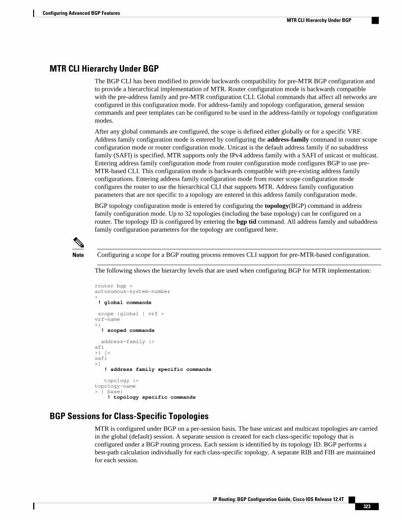
MTR CLI Hierarchy Under BGPThe BGP CLI has been modified to provide backwards compatibility for pre-MTR BGP configuration andto provide a hierarchical implementation of MTR. Router configuration mode is backwards compatiblewith the pre-address family and pre-MTR configuration CLI. Global commands that affect all networks areconfigured in this configuration mode. For address-family and topology configuration, general sessioncommands and peer templates can be configured to be used in the address-family or topology configurationmodes.
After any global commands are configured, the scope is defined either globally or for a specific VRF.Address family configuration mode is entered by configuring the address-family command in router scopeconfiguration mode or router configuration mode. Unicast is the default address family if no subaddressfamily (SAFI) is specified. MTR supports only the IPv4 address family with a SAFI of unicast or multicast.Entering address family configuration mode from router configuration mode configures BGP to use pre-MTR-based CLI. This configuration mode is backwards compatible with pre-existing address familyconfigurations. Entering address family configuration mode from router scope configuration modeconfigures the router to use the hierarchical CLI that supports MTR. Address family configurationparameters that are not specific to a topology are entered in this address family configuration mode.
BGP topology configuration mode is entered by configuring the topology(BGP) command in addressfamily configuration mode. Up to 32 topologies (including the base topology) can be configured on arouter. The topology ID is configured by entering the bgp tid command. All address family and subaddressfamily configuration parameters for the topology are configured here.
Note Configuring a scope for a BGP routing process removes CLI support for pre-MTR-based configuration.
The following shows the hierarchy levels that are used when configuring BGP for MTR implementation:
router bgp <autonomous-system-number> ! global commands
scope {global | vrf <vrf-name>} ! scoped commands
address-family {<afi>} [<safi>] ! address family specific commands
topology {<topology-name> | base} ! topology specific commands
BGP Sessions for Class-Specific TopologiesMTR is configured under BGP on a per-session basis. The base unicast and multicast topologies are carriedin the global (default) session. A separate session is created for each class-specific topology that isconfigured under a BGP routing process. Each session is identified by its topology ID. BGP performs abest-path calculation individually for each class-specific topology. A separate RIB and FIB are maintainedfor each session.
Configuring Advanced BGP FeaturesMTR CLI Hierarchy Under BGP
IP Routing: BGP Configuration Guide, Cisco IOS Release 12.4T 323

Topology Translation Using BGPDepending on the design and policy requirements for your network, you may need to install routes from aclass-specific topology on one router in a class-specific topology on a neighboring router. Topologytranslation functionality using BGP provides support for this operation. Topology translation is BGPneighbor-session based. The neighbor translate-topology command is configured using the IP address andtopology ID from the neighbor.
The topology ID identifies the class-specific topology of the neighbor. The routes in the class-specifictopology of the neighbor are installed in the local class-specific RIB. BGP performs a best-path calculationon all installed routes and installs these routes into the local class-specific RIB. If a duplicate route istranslated, BGP will select and install only one instance of the route per standard BGP best-path calculationbehavior.
Topology Import Using BGPTopology import functionality using BGP is similar to topology translation. The difference is that routesare moved between class-specific topologies on the same router using BGP. This function is configured byentering the import topology command. The name of the class-specific topology or base topology isspecified when entering this command. Best-path calculations are run on the imported routes before theyare installed into the topology RIB. This command also includes a route-map keyword to allow you tofilter routes that are moved between class-specific topologies.
How to Configure Advanced BGP Features• Configuring BGP Next-Hop Address Tracking, page 324• Configuring BGP Nonstop Forwarding Awareness Using BGP Graceful Restart, page 331• Configuring BGP Route Dampening, page 346• Decreasing BGP Convergence Time Using BFD, page 349• Enabling BGP MIB Support, page 353• Configuring BGP Support for MTR, page 354
Configuring BGP Next-Hop Address TrackingThe tasks in this section show how configure BGP next-hop address tracking. BGP next-hop addresstracking significantly improves the response time of BGP to next-hop changes in the RIB. However,unstable Interior Gateway Protocol (IGP) peers can introduce instability to BGP neighbor sessions. Werecommend that you aggressively dampen unstable IGP peering sessions to reduce the possible impact toBGP. For more details about configuring route dampening, see the Configuring BGP Route Dampening, page 346.
• Disabling BGP Next-Hop Address Tracking, page 324• Adjusting the Delay Interval for BGP Next-Hop Address Tracking, page 326• Configuring BGP Selective Next-Hop Route Filtering, page 327
Disabling BGP Next-Hop Address TrackingPerform this task to disable BGP next-hop address tracking. BGP next-hop address tracking is enabled bydefault under the IPv4 and VPNv4 address families. Beginning with Cisco IOS Release 12.2(33)SB6, BGP
Configuring BGP Next-Hop Address Tracking Topology Translation Using BGP
IP Routing: BGP Configuration Guide, Cisco IOS Release 12.4T324
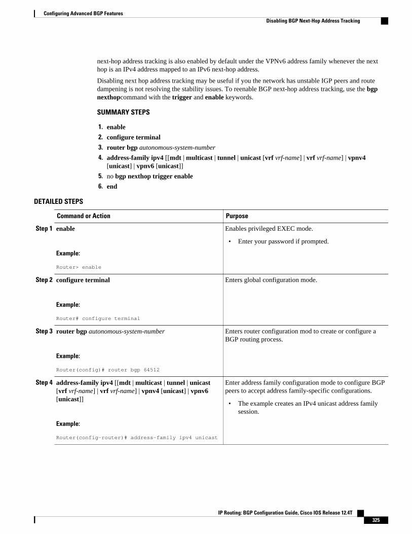
next-hop address tracking is also enabled by default under the VPNv6 address family whenever the nexthop is an IPv4 address mapped to an IPv6 next-hop address.
Disabling next hop address tracking may be useful if you the network has unstable IGP peers and routedampening is not resolving the stability issues. To reenable BGP next-hop address tracking, use the bgpnexthopcommand with the trigger and enable keywords.
SUMMARY STEPS
1. enable
2. configure terminal
3. router bgp autonomous-system-number
4. address-family ipv4 [[mdt | multicast | tunnel | unicast [vrf vrf-name] | vrf vrf-name] | vpnv4[unicast] | vpnv6 [unicast]]
5. no bgp nexthop trigger enable
6. end
DETAILED STEPS
Command or Action Purpose
Step 1 enable
Example:
Router> enable
Enables privileged EXEC mode.
• Enter your password if prompted.
Step 2 configure terminal
Example:
Router# configure terminal
Enters global configuration mode.
Step 3 router bgp autonomous-system-number
Example:
Router(config)# router bgp 64512
Enters router configuration mod to create or configure aBGP routing process.
Step 4 address-family ipv4 [[mdt | multicast | tunnel | unicast[vrf vrf-name] | vrf vrf-name] | vpnv4 [unicast] | vpnv6[unicast]]
Example:
Router(config-router)# address-family ipv4 unicast
Enter address family configuration mode to configure BGPpeers to accept address family-specific configurations.
• The example creates an IPv4 unicast address familysession.
Configuring Advanced BGP FeaturesDisabling BGP Next-Hop Address Tracking
IP Routing: BGP Configuration Guide, Cisco IOS Release 12.4T 325

Command or Action Purpose
Step 5 no bgp nexthop trigger enable
Example:
Router(config-router-af)# no bgp nexthop trigger enable
Disables BGP next-hop address tracking.
• Next-hop address tracking is enabled by default forIPv4 and VPNv4 address family sessions.
• The example disables next-hop address tracking.
Step 6 end
Example:
Router(config-router-af)# end
Exits address-family configuration mode, and entersPrivileged EXEC mode.
Adjusting the Delay Interval for BGP Next-Hop Address TrackingPerform this task to adjust the delay interval between routing table walks for BGP next-hop addresstracking.
You can increase the performance of this feature by tuning the delay interval between full routing tablewalks to match the tuning parameters for the Interior Gateway protocol (IGP). The default delay interval is5 seconds. This value is optimal for a fast-tuned IGP. In the case of an IGP that converges more slowly,you can change the delay interval to 20 seconds or more, depending on the IGP convergence time.
BGP next-hop address tracking significantly improves the response time of BGP to next-hop changes in theRIB. However, unstable Interior Gateway Protocol (IGP) peers can introduce instability to BGP neighborsessions. We recommend that you aggressively dampen unstable IGP peering sessions to reduce thepossible impact to BGP.
SUMMARY STEPS
1. enable
2. configure terminal
3. router bgp autonomous-system-number
4. address-family ipv4 [[mdt | multicast | tunnel | unicast [vrf vrf-name] | vrf vrf-name] | vpnv4[unicast]]
5. bgp nexthop trigger delay delay-timer
6. end
DETAILED STEPS
Command or Action Purpose
Step 1 enable
Example:
Router> enable
Enables privileged EXEC mode.
• Enter your password if prompted.
Configuring Advanced BGP Features Adjusting the Delay Interval for BGP Next-Hop Address Tracking
IP Routing: BGP Configuration Guide, Cisco IOS Release 12.4T326
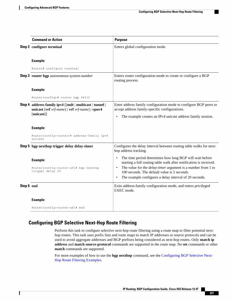
Command or Action Purpose
Step 2 configure terminal
Example:
Router# configure terminal
Enters global configuration mode.
Step 3 router bgp autonomous-system-number
Example:
Router(config)# router bgp 64512
Enters router configuration mode to create or configure a BGProuting process.
Step 4 address-family ipv4 [[mdt | multicast | tunnel |unicast [vrf vrf-name] | vrf vrf-name] | vpnv4[unicast]]
Example:
Router(config-router)# address-family ipv4 unicast
Enter address family configuration mode to configure BGP peers toaccept address family-specific configurations.
• The example creates an IPv4 unicast address family session.
Step 5 bgp nexthop trigger delay delay-timer
Example:
Router(config-router-af)# bgp nexthop trigger delay 20
Configures the delay interval between routing table walks for next-hop address tracking.
• The time period determines how long BGP will wait beforestarting a full routing table walk after notification is received.
• The value for the delay-timer argument is a number from 1 to100 seconds. The default value is 5 seconds.
• The example configures a delay interval of 20 seconds.
Step 6 end
Example:
Router(config-router-af)# end
Exits address-family configuration mode, and enters privilegedEXEC mode.
Configuring BGP Selective Next-Hop Route FilteringPerform this task to configure selective next-hop route filtering using a route map to filter potential next-hop routes. This task uses prefix lists and route maps to match IP addresses or source protocols and can beused to avoid aggregate addresses and BGP prefixes being considered as next-hop routes. Only match ipaddress and match source-protocol commands are supported in the route map. No set commands or othermatch commands are supported.
For more examples of how to use the bgp nexthop command, see the Configuring BGP Selective Next-Hop Route Filtering Examples.
Configuring Advanced BGP FeaturesConfiguring BGP Selective Next-Hop Route Filtering
IP Routing: BGP Configuration Guide, Cisco IOS Release 12.4T 327

SUMMARY STEPS
1. enable
2. configure terminal
3. router bgp autonomous-system-number
4. address-family ipv4 [unicast | multicast| vrf vrf-name]
5. bgp nexthop route-map map-name
6. exit
7. exit
8. ip prefix-list list-name [seq seq-value] {deny network / length | permit network / length}[ge ge-value][le le-value]
9. route-map map-name [permit| deny][sequence-number]
10. match ip address prefix-list prefix-list-name [prefix-list-name...]
11. exit
12. route-map map-name [permit| deny][sequence-number]
13. end
14. show ip bgp [network] [network-mask]
DETAILED STEPS
Command or Action Purpose
Step 1 enable
Example:
Router> enable
Enables privileged EXEC mode.
• Enter your password if prompted.
Step 2 configure terminal
Example:
Router# configure terminal
Enters global configuration mode.
Step 3 router bgp autonomous-system-number
Example:
Router(config)# router bgp 45000
Enters router configuration mode and creates a BGP routing process.
Configuring Advanced BGP Features Configuring BGP Selective Next-Hop Route Filtering
IP Routing: BGP Configuration Guide, Cisco IOS Release 12.4T328

Command or Action Purpose
Step 4 address-family ipv4 [unicast | multicast| vrfvrf-name]
Example:
Router(config-router)# address-family ipv4 unicast
Specifies the IPv4 address family and enters address familyconfiguration mode.
• The unicast keyword specifies the IPv4 unicast address family. Bydefault, the router is placed in address family configuration modefor the IPv4 unicast address family if the unicast keyword is notspecified with the address-family ipv4 command.
• The multicast keyword specifies IPv4 multicast address prefixes.• The vrf keyword and vrf-name argument specify the name of the
VRF instance to associate with subsequent IPv4 address familyconfiguration mode commands.
Step 5 bgp nexthop route-map map-name
Example:
Router(config-router-af)# bgp nexthop route-map CHECK-NEXTHOP
Permits a route map to selectively define routes to help resolve the BGPnext hop.
• In this example the route map named CHECK-NEXTHOP iscreated.
Step 6 exit
Example:
Router(config-router-af)# exit
Exits address family configuration mode and enters routerconfiguration mode.
Step 7 exit
Example:
Router(config-router)# exit
Exits router configuration mode and enters global configuration mode.
Step 8 ip prefix-list list-name [seq seq-value] {deny network / length | permit network / length}[ge ge-value] [le le-value]
Example:
Router(config)# ip prefix-list FILTER25 seq 5 permit 0.0.0.0/0 le 25
Creates a prefix list for BGP next-hop route filtering.
• Selective next-hop route filtering supports prefix length matchingor source protocol matching on a per address-family basis.
• The example creates a prefix list named FILTER25 that permitsroutes only if the mask length is more than 25; this will avoidaggregate routes being considered as the next-hop route.
Step 9 route-map map-name [permit| deny][sequence-number]
Example:
Router(config)# route-map CHECK-NEXTHOP deny 10
Configures a route map and enters route map configuration mode.
• In this example, a route map named CHECK-NEXTHOP iscreated. If there is an IP address match in the following matchcommand, the IP address will be denied.
Configuring Advanced BGP FeaturesConfiguring BGP Selective Next-Hop Route Filtering
IP Routing: BGP Configuration Guide, Cisco IOS Release 12.4T 329

Command or Action Purpose
Step 10 match ip address prefix-list prefix-list-name[prefix-list-name...]
Example:
Router(config-route-map)# match ip address prefix-list FILTER25
Matches the IP addresses in the specified prefix list.
• Use the prefix-list-name argument to specify the name of a prefixlist. The ellipsis means that more than one prefix list can bespecified.
Note Only the syntax applicable to this task is used in this example.For more details, see the Cisco IOS IP Routing: BGP CommandReference.
Step 11 exit
Example:
Router(config-route-map)# exit
Exits route map configuration mode and enters global configurationmode.
Step 12 route-map map-name [permit| deny][sequence-number]
Example:
Router(config)# route-map CHECK-NEXTHOP permit 20
Configures a route map and enters route map configuration mode.
• In this example, all other IP addresses are permitted by route mapCHECK-NEXTHOP.
Step 13 end
Example:
Router(config-route-map)# end
Exits route map configuration mode and enters privileged EXEC mode.
Step 14 show ip bgp [network] [network-mask]
Example:
Router# show ip bgp
Displays the entries in the BGP routing table.
• Enter this command to view the next-hop addresses for each route.
Note Only the syntax applicable to this task is used in this example.For more details, see the Cisco IOS IP Routing: BGP CommandReference.
Example
The following example from the show ip bgp command shows the next-hop addresses for each route:
BGP table version is 7, local router ID is 172.17.1.99Status codes: s suppressed, d damped, h history, * valid, > best, i - internal, r RIB-failure, S StaleOrigin codes: i - IGP, e - EGP, ? - incomplete Network Next Hop Metric LocPrf Weight Path* 10.1.1.0/24 192.168.1.2 0 0 40000 i* 10.2.2.0/24 192.168.3.2 0 0 50000 i*> 172.16.1.0/24 0.0.0.0 0 32768 i*> 172.17.1.0/24 0.0.0.0 0 32768
Configuring Advanced BGP Features Configuring BGP Selective Next-Hop Route Filtering
IP Routing: BGP Configuration Guide, Cisco IOS Release 12.4T330

Configuring BGP Nonstop Forwarding Awareness Using BGP GracefulRestart
The tasks in this section show how configure BGP Nonstop Forwarding (NSF) awareness using the BGPgraceful restart capability. The first task enables BGP NSF globally for all BGP neighbors and suggests afew troubleshooting options. The second task describes how to adjust the BGP graceful restart timersalthough the default settings are optimal for most network deployments. The next three tasks demonstratehow to enable or disable BGP graceful restart for individual BGP neighbors including peer sessiontemplates and peer groups. The final task verifies the local and peer router configuration of BGP NSF.
• Enabling BGP Global NSF Awareness Using BGP Graceful Restart, page 331
• Configuring BGP NSF Awareness Timers, page 333
• Enabling and Disabling BGP Graceful Restart Using BGP Peer Session Templates, page 335
• Enabling BGP Graceful Restart for an Individual BGP Neighbor, page 340
• Disabling BGP Graceful Restart for a BGP Peer Group, page 342
• Verifying the Configuration of BGP Nonstop Forwarding Awareness, page 345
Enabling BGP Global NSF Awareness Using BGP Graceful RestartPerform this task to enable BGP NSF awareness globally for all BGP neighbors. BGP NSF awareness ispart of the graceful restart mechanism and BGP NSF awareness is enabled by issuing the bgp graceful-restart command in router configuration mode. BGP NSF awareness allows NSF-aware routers to supportNSF-capable routers during an SSO operation. NSF-awareness is not enabled by default and should beconfigured on all neighbors that participate in BGP NSF.
Note The configuration of the restart and stale-path timers is not required to enable the BGP graceful restartcapability. The default values are optimal for most network deployments, and these values should beadjusted only by an experienced network operator.
Note Configuring both BFD and BGP graceful restart for NSF on a router running BGP may result in suboptimalrouting. For more details, see "BFD for BGP".
SUMMARY STEPS
1. enable
2. configure terminal
3. router bgp autonomous-system-number
4. bgp graceful-restart [restart-time seconds] [stalepath-time seconds]
5. end
Configuring BGP Nonstop Forwarding Awareness Using BGP Graceful RestartEnabling BGP Global NSF Awareness Using BGP Graceful Restart
IP Routing: BGP Configuration Guide, Cisco IOS Release 12.4T 331
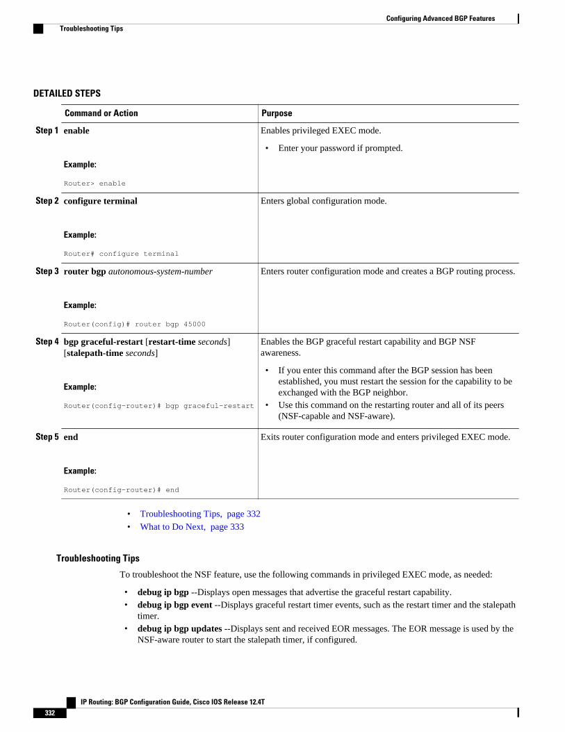
DETAILED STEPS
Command or Action Purpose
Step 1 enable
Example:
Router> enable
Enables privileged EXEC mode.
• Enter your password if prompted.
Step 2 configure terminal
Example:
Router# configure terminal
Enters global configuration mode.
Step 3 router bgp autonomous-system-number
Example:
Router(config)# router bgp 45000
Enters router configuration mode and creates a BGP routing process.
Step 4 bgp graceful-restart [restart-time seconds][stalepath-time seconds]
Example:
Router(config-router)# bgp graceful-restart
Enables the BGP graceful restart capability and BGP NSFawareness.
• If you enter this command after the BGP session has beenestablished, you must restart the session for the capability to beexchanged with the BGP neighbor.
• Use this command on the restarting router and all of its peers(NSF-capable and NSF-aware).
Step 5 end
Example:
Router(config-router)# end
Exits router configuration mode and enters privileged EXEC mode.
• Troubleshooting Tips, page 332
• What to Do Next, page 333
Troubleshooting Tips
To troubleshoot the NSF feature, use the following commands in privileged EXEC mode, as needed:
• debug ip bgp --Displays open messages that advertise the graceful restart capability.• debug ip bgp event --Displays graceful restart timer events, such as the restart timer and the stalepath
timer.• debug ip bgp updates --Displays sent and received EOR messages. The EOR message is used by the
NSF-aware router to start the stalepath timer, if configured.
Configuring Advanced BGP Features Troubleshooting Tips
IP Routing: BGP Configuration Guide, Cisco IOS Release 12.4T332
• show ip bgp --Displays entries in the BGP routing table. The output from this command will displayroutes that are marked as stale by displaying the letter "S" next to each stale route.
• show ip bgp neighbor --Displays information about the TCP and BGP connections to neighbordevices. When enabled, the graceful restart capability is displayed in the output of this command.
What to Do Next
If the bgp graceful-restart command has been issued after the BGP session has been established, you mustreset by issuing the clear ip bgp * command or by reloading the router before graceful restart capabilitieswill be exchanged. For more information about resetting BGP sessions and using the clear ip bgpcommand, see the "Configuring a Basic BGP Network" module.
Configuring BGP NSF Awareness TimersPerform this task to adjust the BGP graceful restart timers. There are two BGP graceful restart timers thatcan be configured. The optional restart-time keyword and seconds argument determine how long peerrouters will wait to delete stale routes before a BGP open message is received. The default value is 120seconds. The optional stalepath-time keyword and seconds argument determine how long a router willwait before deleting stale routes after an end of record (EOR) message is received from the restartingrouter. The default value is 360 seconds.
Note The configuration of the restart and stale-path timers is not required to enable the BGP graceful restartcapability. The default values are optimal for most network deployments, and these values should beadjusted only by an experienced network operator.
SUMMARY STEPS
1. enable
2. configure terminal
3. router bgp autonomous-system-number
4. bgp graceful-restart [restart-timeseconds]
5. bgp graceful-restart [stalepath-time seconds]
6. Router(config-router)# end
DETAILED STEPS
Command or Action Purpose
Step 1 enable
Example:
Router> enable
Enables privileged EXEC mode.
• Enter your password if prompted.
Configuring Advanced BGP FeaturesWhat to Do Next
IP Routing: BGP Configuration Guide, Cisco IOS Release 12.4T 333

Command or Action Purpose
Step 2 configure terminal
Example:
Router# configure terminal
Enters global configuration mode.
Step 3 router bgp autonomous-system-number
Example:
Router(config)# router bgp 45000
Enters router configuration mode and creates a BGP routing process.
Step 4 bgp graceful-restart [restart-timeseconds]
Example:
Router(config-router)# bgp graceful-restart restart-time 130
Enables the BGP graceful restart capability and BGP NSF awareness.
• The restart-time argument determines how long peer routers will waitto delete stale routes before a BGP open message is received.
• The default value is 120 seconds. The configurable range is from 1 to3600 seconds.
Note Only the syntax applicable to this step is used in this example. Formore details, see the Cisco IOS IP Routing: BGP CommandReference.
Step 5 bgp graceful-restart [stalepath-timeseconds]
Example:
Router(config-router)# bgp graceful-restart stalepath-time 350
Enables the BGP graceful restart capability and BGP NSF awareness.
• The stalepath-time argument determines how long a router will waitbefore deleting stale routes after an end of record (EOR) message isreceived from the restarting router.
• The default value is 360 seconds. The configurable range is from 1 to3600 seconds.
Note Only the syntax applicable to this step is used in this example. Formore details, see the Cisco IOS IP Routing: BGP CommandReference.
Step 6 Router(config-router)# end
Example:
Router(config-router)# end
Exits router configuration mode and enters privileged EXEC mode.
• What to Do Next, page 334
What to Do Next
If the bgp graceful-restart command has been issued after the BGP session has been established, you mustreset the peer sessions by issuing the clear ip bgp * command or by reloading the router before gracefulrestart capabilities will be exchanged. For more information about resetting BGP sessions and using theclear ip bgpcommand, see the "Configuring a Basic BGP Network" module.
Configuring Advanced BGP Features What to Do Next
IP Routing: BGP Configuration Guide, Cisco IOS Release 12.4T334
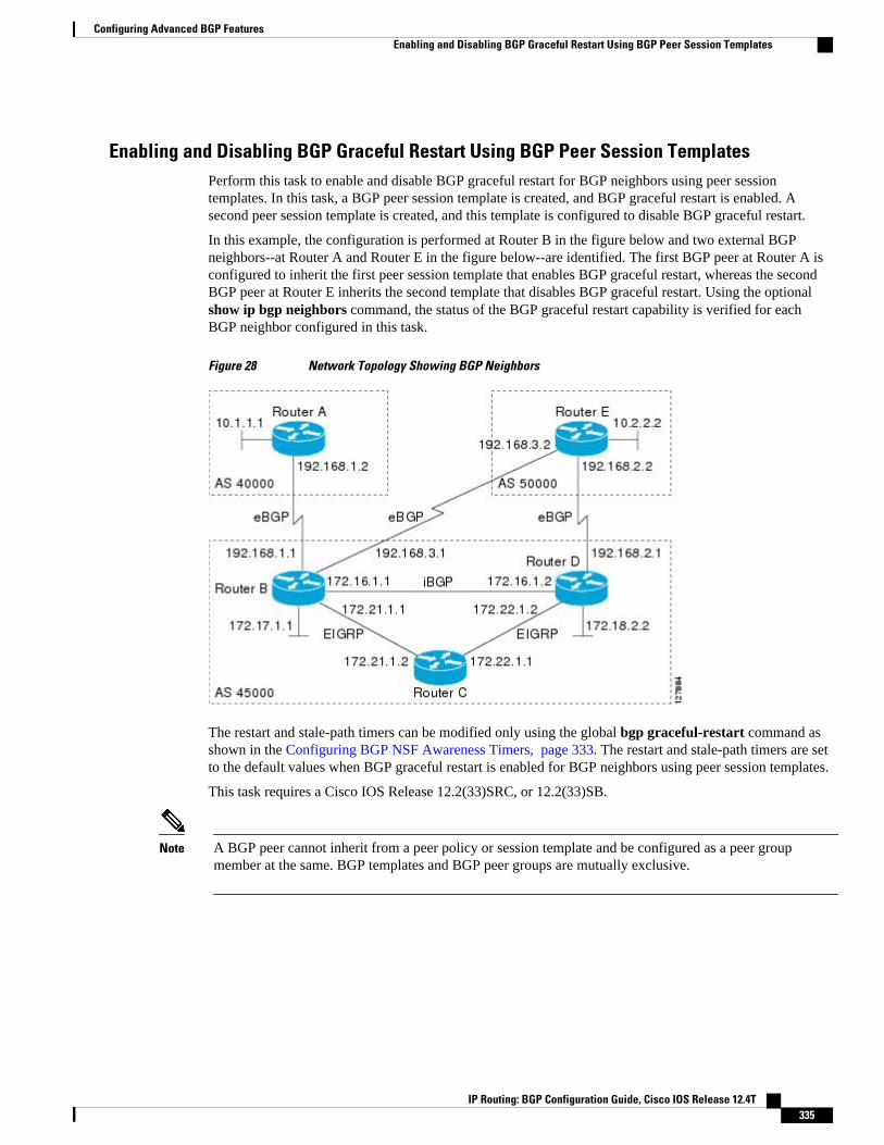
Enabling and Disabling BGP Graceful Restart Using BGP Peer Session TemplatesPerform this task to enable and disable BGP graceful restart for BGP neighbors using peer sessiontemplates. In this task, a BGP peer session template is created, and BGP graceful restart is enabled. Asecond peer session template is created, and this template is configured to disable BGP graceful restart.
In this example, the configuration is performed at Router B in the figure below and two external BGPneighbors--at Router A and Router E in the figure below--are identified. The first BGP peer at Router A isconfigured to inherit the first peer session template that enables BGP graceful restart, whereas the secondBGP peer at Router E inherits the second template that disables BGP graceful restart. Using the optionalshow ip bgp neighbors command, the status of the BGP graceful restart capability is verified for eachBGP neighbor configured in this task.
Figure 28 Network Topology Showing BGP Neighbors
The restart and stale-path timers can be modified only using the global bgp graceful-restart command asshown in the Configuring BGP NSF Awareness Timers, page 333. The restart and stale-path timers are setto the default values when BGP graceful restart is enabled for BGP neighbors using peer session templates.
This task requires a Cisco IOS Release 12.2(33)SRC, or 12.2(33)SB.
Note A BGP peer cannot inherit from a peer policy or session template and be configured as a peer groupmember at the same. BGP templates and BGP peer groups are mutually exclusive.
Configuring Advanced BGP FeaturesEnabling and Disabling BGP Graceful Restart Using BGP Peer Session Templates
IP Routing: BGP Configuration Guide, Cisco IOS Release 12.4T 335

SUMMARY STEPS
1. enable
2. configure terminal
3. router bgp autonomous-system-number
4. template peer-session session-template-name
5. ha-mode graceful-restart [disable]
6. exit-peer-session
7. template peer-session session-template-name
8. ha-mode graceful-restart [disable]
9. exit-peer-session
10. bgp log-neighbor-changes
11. neighbor ip-address remote-as autonomous-system-number
12. neighbor ip-address inherit peer-session session-template-number
13. neighbor ip-address remote-as autonomous-system-number
14. neighbor ip-address inherit peer-session session-template-number
15. end
16. show ip bgp template peer-session [session-template-number]
17. show ip bgp neighbors [ip-address [received-routes | routes | advertised-routes | paths [regexp] |dampened-routes | flap-statistics| received prefix-filter| policy[detail]]]
DETAILED STEPS
Command or Action Purpose
Step 1 enable
Example:
Router> enable
Enables privileged EXEC mode.
• Enter your password if prompted.
Step 2 configure terminal
Example:
Router# configure terminal
Enters global configuration mode.
Step 3 router bgp autonomous-system-number
Example:
Router(config)# router bgp 45000
Enters router configuration mode and creates a BGP routing process.
Configuring Advanced BGP Features Enabling and Disabling BGP Graceful Restart Using BGP Peer Session Templates
IP Routing: BGP Configuration Guide, Cisco IOS Release 12.4T336

Command or Action Purpose
Step 4 template peer-session session-template-name
Example:
Router(config-router)# template peer-session S1
Enters session-template configuration mode and creates a peer sessiontemplate.
• In this example, a peer session template named S1 is created.
Step 5 ha-mode graceful-restart [disable]
Example:
Router(config-router-stmp)# ha-mode graceful-restart
Enables the BGP graceful restart capability and BGP NSF awareness.
• Use the disable keyword to disable BGP graceful restart capability.• If you enter this command after the BGP session has been
established, you must restart the session in order for the capability tobe exchanged with the BGP neighbor.
• In this example, the BGP graceful restart capability is enabled forthe peer session template named S1.
Step 6 exit-peer-session
Example:
Router(config-router-stmp)# exit-peer-session
Exits session-template configuration mode and returns to routerconfiguration mode.
Step 7 template peer-session session-template-name
Example:
Router(config-router)# template peer-session S2
Enters session-template configuration mode and creates a peer sessiontemplate.
• In this example, a peer session template named S2 is created.
Step 8 ha-mode graceful-restart [disable]
Example:
Router(config-router-stmp)# ha-mode graceful-restart disable
Enables the BGP graceful restart capability and BGP NSF awareness.
• Use the disable keyword to disable BGP graceful restart capability.• If you enter this command after the BGP session has been
established, you must restart the session in order for the capability tobe exchanged with the BGP neighbor.
• In this example, the BGP graceful restart capability is disabled forthe peer session template named S2.
Step 9 exit-peer-session
Example:
Router(config-router-stmp)# exit-peer-session
Exits session-template configuration mode and returns to routerconfiguration mode.
Configuring Advanced BGP FeaturesEnabling and Disabling BGP Graceful Restart Using BGP Peer Session Templates
IP Routing: BGP Configuration Guide, Cisco IOS Release 12.4T 337

Command or Action Purpose
Step 10 bgp log-neighbor-changes
Example:
Router(config-router)# bgp log-neighbor-changes
Enables logging of BGP neighbor status changes (up or down) andneighbor resets.
• Use this command for troubleshooting network connectivityproblems and measuring network stability. Unexpected neighborresets might indicate high error rates or high packet loss in thenetwork and should be investigated.
Step 11 neighbor ip-address remote-as autonomous-system-number
Example:
Router(config-router)# neighbor 192.168.1.2 remote-as 40000
Configures peering with a BGP neighbor in the specified autonomoussystem.
• In this example, the BGP peer at 192.168.1.2 is an external BGPpeer because it has a different autonomous system number from therouter where the BGP configuration is being entered (see Step 3).
Step 12 neighbor ip-address inherit peer-sessionsession-template-number
Example:
Router(config-router)# neighbor 192.168.1.2 inherit peer-session S1
Inherits a peer session template.
• In this example, the peer session template named S1 is inherited, andthe neighbor inherits the enabling of BGP graceful restart.
Step 13 neighbor ip-address remote-as autonomous-system-number
Example:
Router(config-router)# neighbor 192.168.3.2 remote-as 50000
Configures peering with a BGP neighbor in the specified autonomoussystem.
• In this example, the BGP peer at 192.168.3.2 is an external BGPpeer because it has a different autonomous system number from therouter where the BGP configuration is being entered (see Step 3).
Step 14 neighbor ip-address inherit peer-sessionsession-template-number
Example:
Router(config-router)# neighbor 192.168.3.2 inherit peer-session S2
Inherits a peer session-template.
• In this example, the peer session template named S2 is inherited, andthe neighbor inherits the disabling of BGP graceful restart.
Step 15 end
Example:
Router(config-router)# end
Exits router configuration mode and enters privileged EXEC mode.
Configuring Advanced BGP Features Enabling and Disabling BGP Graceful Restart Using BGP Peer Session Templates
IP Routing: BGP Configuration Guide, Cisco IOS Release 12.4T338

Command or Action Purpose
Step 16 show ip bgp template peer-session [session-template-number]
Example:
Router# show ip bgp template peer-session
(Optional) Displays locally configured peer session templates.
• The output can be filtered to display a single peer policy templatewith the session-template-name argument. This command alsosupports all standard output modifiers.
Step 17 show ip bgp neighbors [ip-address [received-routes | routes | advertised-routes| paths [regexp] | dampened-routes | flap-statistics| received prefix-filter|policy[detail]]]
Example:
Router# show ip bgp neighbors 192.168.1.2
(Optional) Displays information about TCP and BGP connections toneighbors.
• "Graceful Restart Capability: advertised" will be displayed for eachneighbor that has exchanged graceful restart capabilities with thisrouter.
• In this example, the output is filtered to display information aboutthe BGP peer at 192.168.1.2.
Examples
The following example shows partial output from the show ip bgp neighbors command for the BGP peer at192.168.1.2 (Router A in the figure above). Graceful restart is shown as enabled. Note the default valuesfor the restart and stale-path timers. These timers can only be set using the global bgp graceful-restartcommand.
Router# show ip bgp neighbors 192.168.1.2BGP neighbor is 192.168.1.2, remote AS 40000, external link Inherits from template S1 for session parameters BGP version 4, remote router ID 192.168.1.2 BGP state = Established, up for 00:02:11 Last read 00:00:23, last write 00:00:27, hold time is 180, keepalive intervals Neighbor sessions: 1 active, is multisession capable Neighbor capabilities: Route refresh: advertised and received(new) Address family IPv4 Unicast: advertised and received Graceful Restart Capability: advertised Multisession Capability: advertised and received!Address tracking is enabled, the RIB does have a route to 192.168.1.2 Connections established 1; dropped 0 Last reset never Transport(tcp) path-mtu-discovery is enabled Graceful-Restart is enabled, restart-time 120 seconds, stalepath-time 360 secsConnection state is ESTAB, I/O status: 1, unread input bytes: 0
The following example shows partial output from the show ip bgp neighbors command for the BGP peerat 192.168.3.2 (Router E in the figure above). Graceful restart is shown as disabled.
Router# show ip bgp neighbors 192.168.3.2BGP neighbor is 192.168.3.2, remote AS 50000, external link Inherits from template S2 for session parameters BGP version 4, remote router ID 192.168.3.2 BGP state = Established, up for 00:01:41 Last read 00:00:45, last write 00:00:45, hold time is 180, keepalive intervals Neighbor sessions:
Configuring Advanced BGP FeaturesEnabling and Disabling BGP Graceful Restart Using BGP Peer Session Templates
IP Routing: BGP Configuration Guide, Cisco IOS Release 12.4T 339
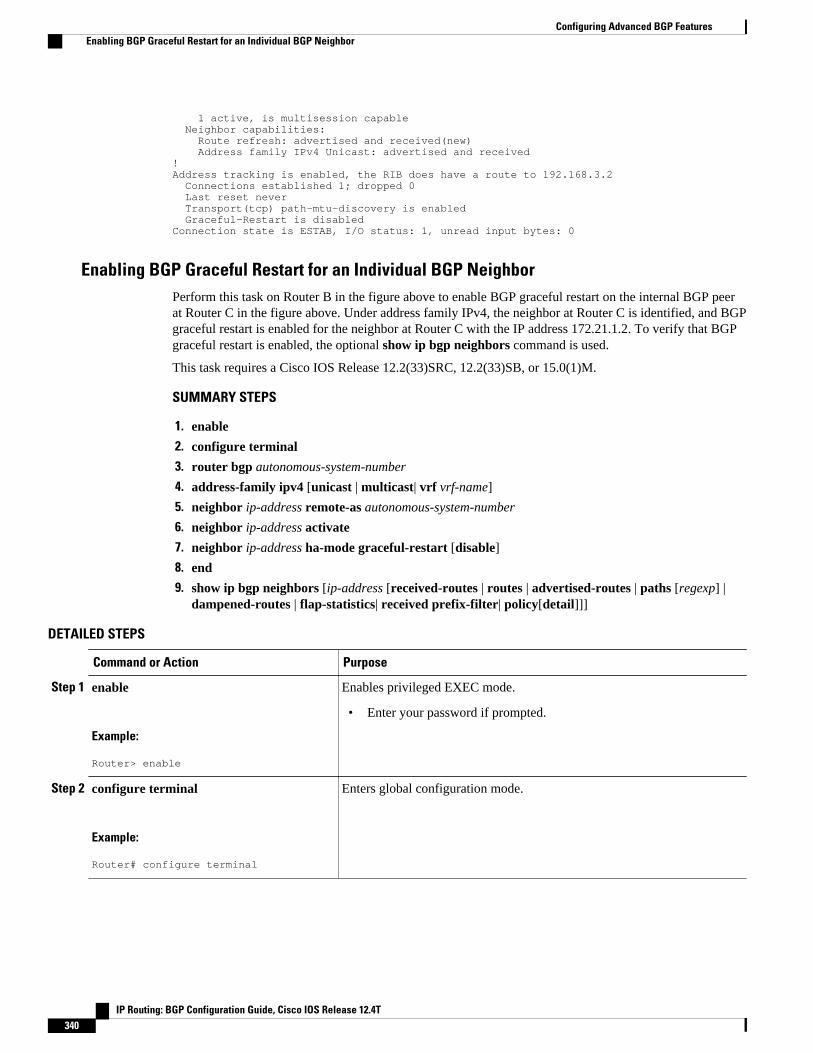
1 active, is multisession capable Neighbor capabilities: Route refresh: advertised and received(new) Address family IPv4 Unicast: advertised and received!Address tracking is enabled, the RIB does have a route to 192.168.3.2 Connections established 1; dropped 0 Last reset never Transport(tcp) path-mtu-discovery is enabled Graceful-Restart is disabledConnection state is ESTAB, I/O status: 1, unread input bytes: 0
Enabling BGP Graceful Restart for an Individual BGP NeighborPerform this task on Router B in the figure above to enable BGP graceful restart on the internal BGP peerat Router C in the figure above. Under address family IPv4, the neighbor at Router C is identified, and BGPgraceful restart is enabled for the neighbor at Router C with the IP address 172.21.1.2. To verify that BGPgraceful restart is enabled, the optional show ip bgp neighbors command is used.
This task requires a Cisco IOS Release 12.2(33)SRC, 12.2(33)SB, or 15.0(1)M.
SUMMARY STEPS
1. enable
2. configure terminal
3. router bgp autonomous-system-number
4. address-family ipv4 [unicast | multicast| vrf vrf-name]
5. neighbor ip-address remote-as autonomous-system-number
6. neighbor ip-address activate
7. neighbor ip-address ha-mode graceful-restart [disable]
8. end
9. show ip bgp neighbors [ip-address [received-routes | routes | advertised-routes | paths [regexp] |dampened-routes | flap-statistics| received prefix-filter| policy[detail]]]
DETAILED STEPS
Command or Action Purpose
Step 1 enable
Example:
Router> enable
Enables privileged EXEC mode.
• Enter your password if prompted.
Step 2 configure terminal
Example:
Router# configure terminal
Enters global configuration mode.
Configuring Advanced BGP Features Enabling BGP Graceful Restart for an Individual BGP Neighbor
IP Routing: BGP Configuration Guide, Cisco IOS Release 12.4T340
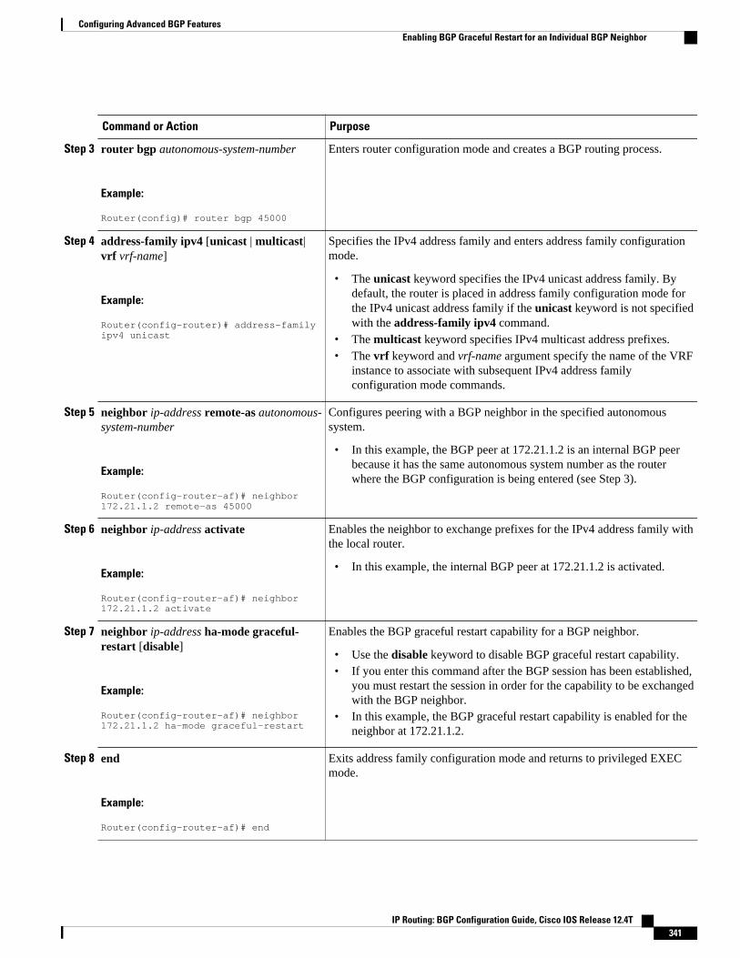
Command or Action Purpose
Step 3 router bgp autonomous-system-number
Example:
Router(config)# router bgp 45000
Enters router configuration mode and creates a BGP routing process.
Step 4 address-family ipv4 [unicast | multicast|vrf vrf-name]
Example:
Router(config-router)# address-family ipv4 unicast
Specifies the IPv4 address family and enters address family configurationmode.
• The unicast keyword specifies the IPv4 unicast address family. Bydefault, the router is placed in address family configuration mode forthe IPv4 unicast address family if the unicast keyword is not specifiedwith the address-family ipv4 command.
• The multicast keyword specifies IPv4 multicast address prefixes.• The vrf keyword and vrf-name argument specify the name of the VRF
instance to associate with subsequent IPv4 address familyconfiguration mode commands.
Step 5 neighbor ip-address remote-as autonomous-system-number
Example:
Router(config-router-af)# neighbor 172.21.1.2 remote-as 45000
Configures peering with a BGP neighbor in the specified autonomoussystem.
• In this example, the BGP peer at 172.21.1.2 is an internal BGP peerbecause it has the same autonomous system number as the routerwhere the BGP configuration is being entered (see Step 3).
Step 6 neighbor ip-address activate
Example:
Router(config-router-af)# neighbor 172.21.1.2 activate
Enables the neighbor to exchange prefixes for the IPv4 address family withthe local router.
• In this example, the internal BGP peer at 172.21.1.2 is activated.
Step 7 neighbor ip-address ha-mode graceful-restart [disable]
Example:
Router(config-router-af)# neighbor 172.21.1.2 ha-mode graceful-restart
Enables the BGP graceful restart capability for a BGP neighbor.
• Use the disable keyword to disable BGP graceful restart capability.• If you enter this command after the BGP session has been established,
you must restart the session in order for the capability to be exchangedwith the BGP neighbor.
• In this example, the BGP graceful restart capability is enabled for theneighbor at 172.21.1.2.
Step 8 end
Example:
Router(config-router-af)# end
Exits address family configuration mode and returns to privileged EXECmode.
Configuring Advanced BGP FeaturesEnabling BGP Graceful Restart for an Individual BGP Neighbor
IP Routing: BGP Configuration Guide, Cisco IOS Release 12.4T 341

Command or Action Purpose
Step 9 show ip bgp neighbors [ip-address [received-routes | routes | advertised-routes | paths [regexp] | dampened-routes |flap-statistics| received prefix-filter|policy[detail]]]
Example:
Router# show ip bgp neighbors 172.21.1.2
(Optional) Displays information about TCP and BGP connections toneighbors.
• "Graceful Restart Capability: advertised" will be displayed for eachneighbor that has exchanged graceful restart capabilities with thisrouter.
• In this example, the output is filtered to display information about theBGP peer at 172.21.1.2.
Examples
The following example shows partial output from the show ip bgp neighbors command for the BGP peerat 172.21.1.2. Graceful restart is shown as enabled. Note the default values for the restart and stale-pathtimers. These timers can be set using only the global bgp graceful-restart command.
Router# show ip bgp neighbors 172.21.1.2BGP neighbor is 172.21.1.2, remote AS 45000, internal link BGP version 4, remote router ID 172.22.1.1 BGP state = Established, up for 00:01:01 Last read 00:00:02, last write 00:00:07, hold time is 180, keepalive intervals Neighbor sessions: 1 active, is multisession capable Neighbor capabilities: Route refresh: advertised and received(new) Address family IPv4 Unicast: advertised and received Graceful Restart Capability: advertised Multisession Capability: advertised and received! Address tracking is enabled, the RIB does have a route to 172.21.1.2 Connections established 1; dropped 0 Last reset never Transport(tcp) path-mtu-discovery is enabled Graceful-Restart is enabled, restart-time 120 seconds, stalepath-time 360 secsConnection state is ESTAB, I/O status: 1, unread input bytes: 0
Disabling BGP Graceful Restart for a BGP Peer GroupPerform this task to disable BGP graceful restart for a BGP peer group. In this task, a BGP peer group iscreated and graceful restart is disabled for the peer group. A BGP neighbor, 172.16.1.2 at Router D in thefigure above, is then identified and added as a peer group member and inherits the configuration associatedwith the peer group, which, in this example, disables BGP graceful restart.
This task requires a Cisco IOS Release 12.2(33)SRC, 12.2(33)SB, or 15.0(1)M.
Configuring Advanced BGP Features Disabling BGP Graceful Restart for a BGP Peer Group
IP Routing: BGP Configuration Guide, Cisco IOS Release 12.4T342
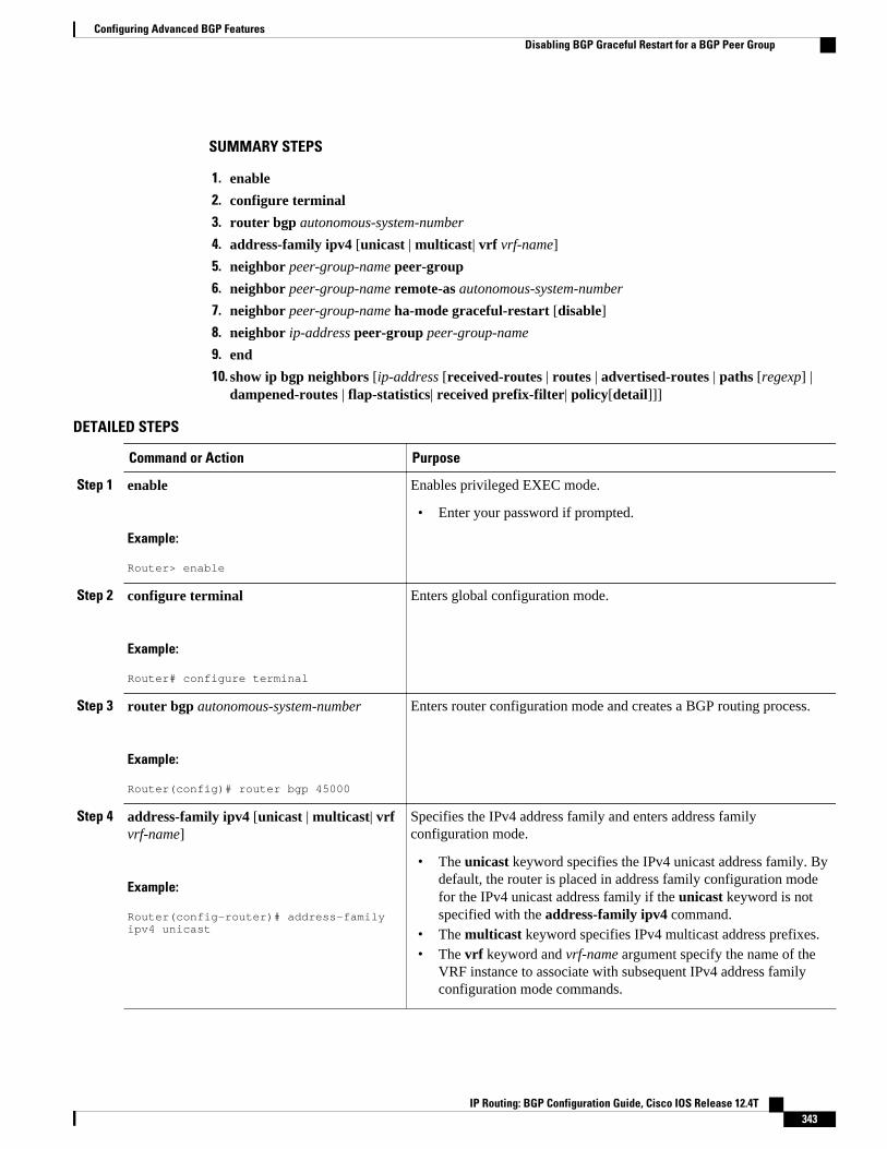
SUMMARY STEPS
1. enable
2. configure terminal
3. router bgp autonomous-system-number
4. address-family ipv4 [unicast | multicast| vrf vrf-name]
5. neighbor peer-group-name peer-group
6. neighbor peer-group-name remote-as autonomous-system-number
7. neighbor peer-group-name ha-mode graceful-restart [disable]
8. neighbor ip-address peer-group peer-group-name
9. end
10. show ip bgp neighbors [ip-address [received-routes | routes | advertised-routes | paths [regexp] |dampened-routes | flap-statistics| received prefix-filter| policy[detail]]]
DETAILED STEPS
Command or Action Purpose
Step 1 enable
Example:
Router> enable
Enables privileged EXEC mode.
• Enter your password if prompted.
Step 2 configure terminal
Example:
Router# configure terminal
Enters global configuration mode.
Step 3 router bgp autonomous-system-number
Example:
Router(config)# router bgp 45000
Enters router configuration mode and creates a BGP routing process.
Step 4 address-family ipv4 [unicast | multicast| vrfvrf-name]
Example:
Router(config-router)# address-family ipv4 unicast
Specifies the IPv4 address family and enters address familyconfiguration mode.
• The unicast keyword specifies the IPv4 unicast address family. Bydefault, the router is placed in address family configuration modefor the IPv4 unicast address family if the unicast keyword is notspecified with the address-family ipv4 command.
• The multicast keyword specifies IPv4 multicast address prefixes.• The vrf keyword and vrf-name argument specify the name of the
VRF instance to associate with subsequent IPv4 address familyconfiguration mode commands.
Configuring Advanced BGP FeaturesDisabling BGP Graceful Restart for a BGP Peer Group
IP Routing: BGP Configuration Guide, Cisco IOS Release 12.4T 343

Command or Action Purpose
Step 5 neighbor peer-group-name peer-group
Example:
Router(config-router-af)# neighbor PG1 peer-group
Creates a BGP peer group.
• In this example, the peer group named PG1 is created.
Step 6 neighbor peer-group-name remote-asautonomous-system-number
Example:
Router(config-router-af)# neighbor PG1 remote-as 45000
Configures peering with a BGP peer group in the specified autonomoussystem.
• In this example, the BGP peer group named PG1 is added to theIPv4 multiprotocol BGP neighbor table of the local router.
Step 7 neighbor peer-group-name ha-modegraceful-restart [disable]
Example:
Router(config-router-af)# neighbor PG1 ha-mode graceful-restart disable
Enables the BGP graceful restart capability for a BGP neighbor.
• Use the disable keyword to disable BGP graceful restart capability.• If you enter this command after the BGP session has been
established, you must restart the session for the capability to beexchanged with the BGP neighbor.
• In this example, the BGP graceful restart capability is disabled forthe BGP peer group named PG1.
Step 8 neighbor ip-address peer-group peer-group-name
Example:
Router(config-router-af)# neighbor 172.16.1.2 peer-group PG1
Assigns the IP address of a BGP neighbor to a peer group.
• In this example, the BGP neighbor peer at 172.16.1.2 is configuredas a member of the peer group named PG1.
Step 9 end
Example:
Router(config-router-af)# end
Exits address family configuration mode and returns to privilegedEXEC mode.
Step 10 show ip bgp neighbors [ip-address [received-routes | routes | advertised-routes | paths[regexp] | dampened-routes | flap-statistics|received prefix-filter| policy[detail]]]
Example:
Router# show ip bgp neighbors 172.16.1.2
(Optional) Displays information about TCP and BGP connections toneighbors.
• In this example, the output is filtered to display information aboutthe BGP peer at 172.16.1.2 and the "Graceful-Restart is disabled"line shows that the graceful restart capability is disabled for thisneighbor.
Configuring Advanced BGP Features Disabling BGP Graceful Restart for a BGP Peer Group
IP Routing: BGP Configuration Guide, Cisco IOS Release 12.4T344

Examples
The following example shows partial output from the show ip bgp neighbors command for the BGP peerat 172.16.1.2. Graceful restart is shown as disabled. Note the default values for the restart and stale-pathtimers. These timers can be set using only the global bgp graceful-restart command.
Router# show ip bgp neighbors 172.16.1.2BGP neighbor is 172.16.1.2, remote AS 45000, internal link Member of peer-group PG1 for session parameters BGP version 4, remote router ID 0.0.0.0 BGP state = Idle Neighbor sessions: 0 active, is multisession capable!Address tracking is enabled, the RIB does have a route to 172.16.1.2 Connections established 0; dropped 0 Last reset never Transport(tcp) path-mtu-discovery is enabled Graceful-Restart is disabled
Verifying the Configuration of BGP Nonstop Forwarding AwarenessUse the following steps to verify the local configuration of BGP NSF awareness on a router and to verifythe configuration of NSF awareness on peer routers in a BGP network.
SUMMARY STEPS
1. enable
2. show running-config [options]
3. show ip bgp neighbors [ip-address [received-routes | routes | advertised-routes | paths [regexp] |dampened-routes | flap-statistics| received prefix-filter| policy[detail]]]
DETAILED STEPS
Step 1 enableEnables privileged EXEC mode. Enter your password if prompted.
Example:
Router> enable
Step 2 show running-config [options]Displays the running configuration on the local router. The output will display the configuration of the bgp graceful-restart command in the BGP section. Repeat this command on all BGP neighbor routers to verify that all BGP peersare configured for BGP NSF awareness. In this example, BGP graceful restart is enabled globally and the externalneighbor at 192.168.1.2 is configured to be a BGP peer and will have the BGP graceful restart capability enabled.
Example:
Router# show running-config...router bgp 45000 bgp router-id 172.17.1.99 bgp log-neighbor-changes
Configuring Advanced BGP FeaturesVerifying the Configuration of BGP Nonstop Forwarding Awareness
IP Routing: BGP Configuration Guide, Cisco IOS Release 12.4T 345

bgp graceful-restart restart-time 130 bgp graceful-restart stalepath-time 350 bgp graceful-restart timers bgp 70 120 neighbor 192.168.1.2 remote-as 40000 neighbor 192.168.1.2 activate...
Step 3 show ip bgp neighbors [ip-address [received-routes | routes | advertised-routes | paths [regexp] | dampened-routes | flap-statistics| received prefix-filter| policy[detail]]]Displays information about TCP and BGP connections to neighbors. "Graceful Restart Capability: advertised" will bedisplayed for each neighbor that has exchanged graceful restart capabilities with this router. In Cisco IOS Releases12.2(33)SRC, 12.2(33)SB, or later releases, the ability to enable or disable the BGP graceful restart capability for anindividual BGP neighbor, peer group or peer session template was introduced and output was added to this commandto show the BGP graceful restart status.
The following partial output example using a Cisco IOS Release 12.2(33)SRC image, displays the graceful restartinformation for internal BGP neighbor 172.21.1.2 at Router C in the figure above. Note the "Graceful-Restart isenabled" message.
Example:
Router# show ip bgp neighbors 172.21.1.2 BGP neighbor is 172.21.1.2, remote AS 45000, internal link BGP version 4, remote router ID 172.22.1.1 BGP state = Established, up for 00:01:01 Last read 00:00:02, last write 00:00:07, hold time is 180, keepalive intervals Neighbor sessions: 1 active, is multisession capable Neighbor capabilities: Route refresh: advertised and received(new) Address family IPv4 Unicast: advertised and received Graceful Restart Capability: advertised Multisession Capability: advertised and received! Address tracking is enabled, the RIB does have a route to 172.21.1.2 Connections established 1; dropped 0 Last reset never Transport(tcp) path-mtu-discovery is enabled Graceful-Restart is enabled, restart-time 120 seconds, stalepath-time 360 secs
Configuring BGP Route DampeningThe tasks in this section configure and monitor BGP route dampening. Route dampening is designed tominimize the propagation of flapping routes across an internetwork. A route is considered to be flappingwhen its availability alternates repeatedly.
• Enabling and Configuring BGP Route Dampening, page 346
• Monitoring and Maintaining BGP Route Dampening, page 348
Enabling and Configuring BGP Route DampeningPerform this task to enable and configure BGP route dampening.
Configuring BGP Route Dampening Enabling and Configuring BGP Route Dampening
IP Routing: BGP Configuration Guide, Cisco IOS Release 12.4T346
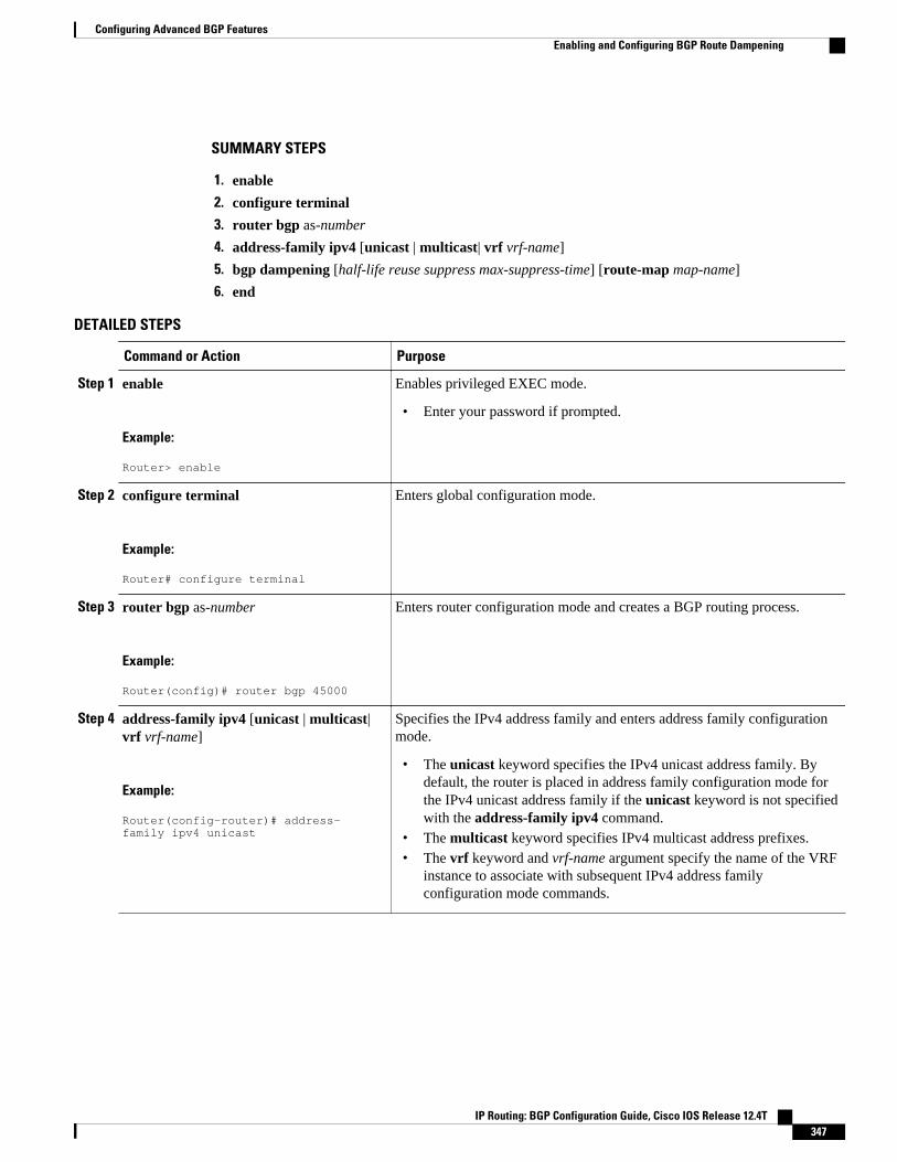
SUMMARY STEPS
1. enable
2. configure terminal
3. router bgp as-number
4. address-family ipv4 [unicast | multicast| vrf vrf-name]
5. bgp dampening [half-life reuse suppress max-suppress-time] [route-map map-name]
6. end
DETAILED STEPS
Command or Action Purpose
Step 1 enable
Example:
Router> enable
Enables privileged EXEC mode.
• Enter your password if prompted.
Step 2 configure terminal
Example:
Router# configure terminal
Enters global configuration mode.
Step 3 router bgp as-number
Example:
Router(config)# router bgp 45000
Enters router configuration mode and creates a BGP routing process.
Step 4 address-family ipv4 [unicast | multicast|vrf vrf-name]
Example:
Router(config-router)# address-family ipv4 unicast
Specifies the IPv4 address family and enters address family configurationmode.
• The unicast keyword specifies the IPv4 unicast address family. Bydefault, the router is placed in address family configuration mode forthe IPv4 unicast address family if the unicast keyword is not specifiedwith the address-family ipv4 command.
• The multicast keyword specifies IPv4 multicast address prefixes.• The vrf keyword and vrf-name argument specify the name of the VRF
instance to associate with subsequent IPv4 address familyconfiguration mode commands.
Configuring Advanced BGP FeaturesEnabling and Configuring BGP Route Dampening
IP Routing: BGP Configuration Guide, Cisco IOS Release 12.4T 347

Command or Action Purpose
Step 5 bgp dampening [half-life reuse suppressmax-suppress-time] [route-map map-name]
Example:
Router(config-router-af)# bgp dampening 30 1500 10000 120
Enables BGP route dampening and changes the default values of routedampening factors.
• The half-life, reuse, suppress, and max-suppress-time arguments areall position dependent; if one argument is entered then all thearguments must be entered.
• Use the route-map keyword and map-name argument to controlwhere BGP route dampening is enabled.
Step 6 end
Example:
Router(config-router-af)# end
Exits address family configuration mode and enters privileged EXECmode.
Monitoring and Maintaining BGP Route DampeningPerform the steps in this task as required to monitor and maintain BGP route dampening.
SUMMARY STEPS
1. enable
2. show ip bgp flap-statistics [regexp regexp | filter-list access-list | ip-address mask [longer-prefix]]
3. clear ip bgp flap-statistics [neighbor-address [ipv4-mask]] [regexp regexp | filter-list extcom-number]
4. show ip bgp dampened-paths
5. clear ip bgp [ipv4 {multicast | unicast} | ipv6{multicast | unicast} | vpnv4 unicast] dampening[neighbor-address] [ipv4-mask]
DETAILED STEPS
Step 1 enableEnables privileged EXEC mode. Enter your password if prompted.
Example:
Router> enable
Step 2 show ip bgp flap-statistics [regexp regexp | filter-list access-list | ip-address mask [longer-prefix]]Use this command to monitor the flaps of all the paths that are flapping. The statistics will be deleted once the route isnot suppressed and is stable for at least one half-life.
Example:
Router# show ip bgp flap-statisticsBGP table version is 10, local router ID is 172.17.232.182Status codes: s suppressed, d damped, h history, * valid, > best, i - internal
Configuring Advanced BGP Features Monitoring and Maintaining BGP Route Dampening
IP Routing: BGP Configuration Guide, Cisco IOS Release 12.4T348
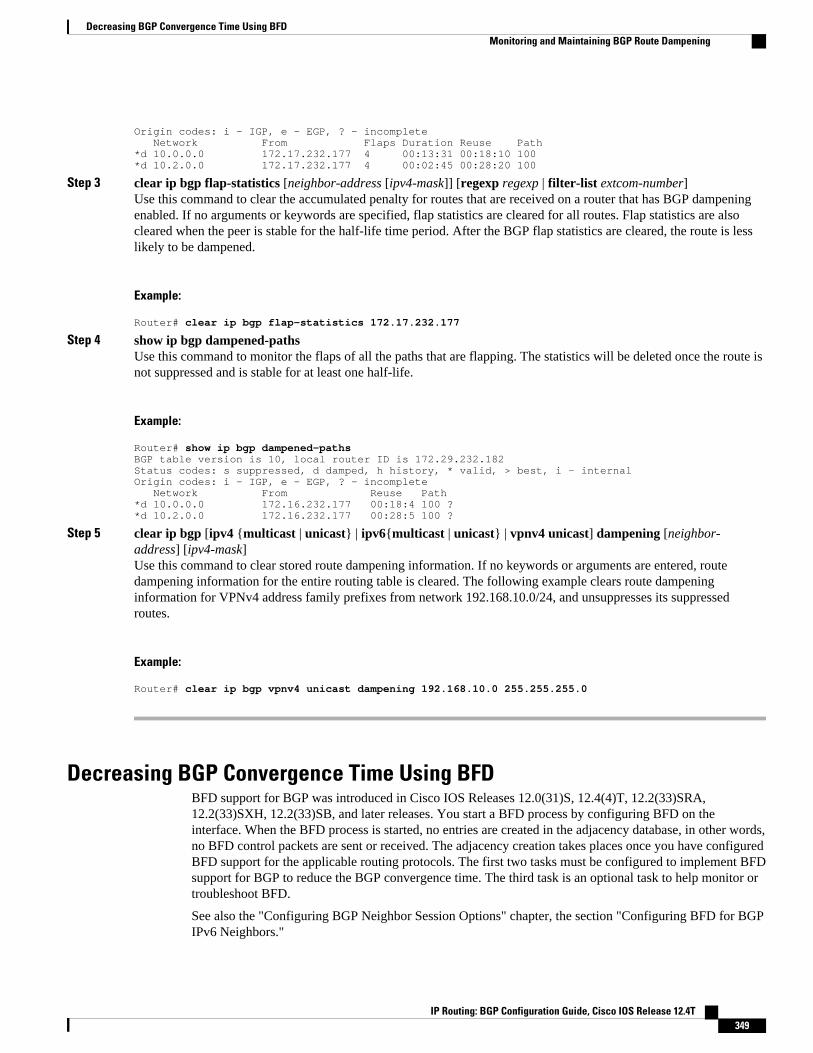
Origin codes: i - IGP, e - EGP, ? - incomplete Network From Flaps Duration Reuse Path*d 10.0.0.0 172.17.232.177 4 00:13:31 00:18:10 100*d 10.2.0.0 172.17.232.177 4 00:02:45 00:28:20 100
Step 3 clear ip bgp flap-statistics [neighbor-address [ipv4-mask]] [regexp regexp | filter-list extcom-number]Use this command to clear the accumulated penalty for routes that are received on a router that has BGP dampeningenabled. If no arguments or keywords are specified, flap statistics are cleared for all routes. Flap statistics are alsocleared when the peer is stable for the half-life time period. After the BGP flap statistics are cleared, the route is lesslikely to be dampened.
Example:
Router# clear ip bgp flap-statistics 172.17.232.177
Step 4 show ip bgp dampened-pathsUse this command to monitor the flaps of all the paths that are flapping. The statistics will be deleted once the route isnot suppressed and is stable for at least one half-life.
Example:
Router# show ip bgp dampened-pathsBGP table version is 10, local router ID is 172.29.232.182Status codes: s suppressed, d damped, h history, * valid, > best, i - internalOrigin codes: i - IGP, e - EGP, ? - incomplete Network From Reuse Path*d 10.0.0.0 172.16.232.177 00:18:4 100 ?*d 10.2.0.0 172.16.232.177 00:28:5 100 ?
Step 5 clear ip bgp [ipv4 {multicast | unicast} | ipv6{multicast | unicast} | vpnv4 unicast] dampening [neighbor-address] [ipv4-mask]Use this command to clear stored route dampening information. If no keywords or arguments are entered, routedampening information for the entire routing table is cleared. The following example clears route dampeninginformation for VPNv4 address family prefixes from network 192.168.10.0/24, and unsuppresses its suppressedroutes.
Example:
Router# clear ip bgp vpnv4 unicast dampening 192.168.10.0 255.255.255.0
Decreasing BGP Convergence Time Using BFDBFD support for BGP was introduced in Cisco IOS Releases 12.0(31)S, 12.4(4)T, 12.2(33)SRA,12.2(33)SXH, 12.2(33)SB, and later releases. You start a BFD process by configuring BFD on theinterface. When the BFD process is started, no entries are created in the adjacency database, in other words,no BFD control packets are sent or received. The adjacency creation takes places once you have configuredBFD support for the applicable routing protocols. The first two tasks must be configured to implement BFDsupport for BGP to reduce the BGP convergence time. The third task is an optional task to help monitor ortroubleshoot BFD.
See also the "Configuring BGP Neighbor Session Options" chapter, the section "Configuring BFD for BGPIPv6 Neighbors."
Decreasing BGP Convergence Time Using BFDMonitoring and Maintaining BGP Route Dampening
IP Routing: BGP Configuration Guide, Cisco IOS Release 12.4T 349

• Prerequisites, page 350
• Restrictions, page 350
• Configuring BFD Session Parameters on the Interface, page 350
• Configuring BFD Support for BGP, page 351
• Monitoring and Troubleshooting BFD for Cisco 7600 Series Routers, page 353
Prerequisites
• Cisco Express Forwarding (CEF) and IP routing must be enabled on all participating routers.• BGP must be configured on the routers before BFD is deployed. You should implement fast
convergence for the routing protocol that you are using. See the IP routing documentation for yourversion of Cisco IOS software for information on configuring fast convergence.
Restrictions
• For the current Cisco implementation of BFD support for BGP in Cisco IOS Releases 12.0(31)S,12.4(4)T, 12.2(33)SRA, 12.2(33)SXH, and 12.2(33)SB, BFD is supported only for IPv4 networks, andonly asynchronous mode is supported. In asynchronous mode, either BFD peer can initiate a BFDsession.
• BFD works only for directly-connected neighbors. BFD neighbors must be no more than one IP hopaway. Multihop configurations are not supported.
• Configuring both BFD and BGP graceful restart for NSF on a router running BGP may result insuboptimal routing. For more details, see the BFD for BGP, page 320.
Configuring BFD Session Parameters on the InterfaceThe steps in this procedure show how to configure BFD on the interface by setting the baseline BFDsession parameters on an interface. Repeat the steps in this procedure for each interface over which youwant to run BFD sessions to BFD neighbors.
SUMMARY STEPS
1. enable
2. configure terminal
3. interface type number
4. bfd interval milliseconds min_rx milliseconds multiplier interval-multiplier
5. end
DETAILED STEPS
Command or Action Purpose
Step 1 enable
Example:
Router> enable
Enables privileged EXEC mode.
• Enter your password if prompted.
Configuring Advanced BGP Features Prerequisites
IP Routing: BGP Configuration Guide, Cisco IOS Release 12.4T350

Command or Action Purpose
Step 2 configure terminal
Example:
Router# configure terminal
Enters global configuration mode.
Step 3 interface type number
Example:
Router(config)# interface FastEthernet 6/0
Enters interface configuration mode.
Step 4 bfd interval milliseconds min_rx milliseconds multiplier interval-multiplier
Example:
Router(config-if)# bfd interval 50 min_rx 50 multiplier 5
Enables BFD on the interface.
Step 5 end
Example:
Router(config-if)# end
Exits interface configuration mode.
Configuring BFD Support for BGPPerform this task to configure BFD support for BGP, so that BGP is a registered protocol with BFD andwill receive forwarding path detection failure messages from BFD.
• BGP must be running on all participating routers.• The baseline parameters for BFD sessions on the interfaces over which you want to run BFD sessions
to BFD neighbors must be configured. See "Configuring BFD Session Parameters on the Interface" formore information.
SUMMARY STEPS
1. enable
2. configure terminal
3. router bgp autonomous-system-number
4. neighbor ip-address fall-over bfd
5. end
6. show bfd neighbors [details]
7. show ip bgp neighbors [ip-address [received-routes | routes | advertised-routes | paths [regexp] |dampened-routes | flap-statistics| received prefix-filter| policy[detail]]]
Configuring Advanced BGP FeaturesConfiguring BFD Support for BGP
IP Routing: BGP Configuration Guide, Cisco IOS Release 12.4T 351

DETAILED STEPS
Command or Action Purpose
Step 1 enable
Example:
Router> enable
Enables privileged EXEC mode.
• Enter your password if prompted.
Step 2 configure terminal
Example:
Router# configure terminal
Enters global configuration mode.
Step 3 router bgp autonomous-system-number
Example:
Router(config)# router bgp tag1
Specifies a BGP process and enters routerconfiguration mode.
Step 4 neighbor ip-address fall-over bfd
Example:
Router(config-router)# neighbor 172.16.10.2 fall-over bfd
Enables BFD support for fallover.
Step 5 end
Example:
Router(config-router)# end
Returns the router to privileged EXEC mode.
Step 6 show bfd neighbors [details]
Example:
Router# show bfd neighbors detail
Verifies that the BFD neighbor is active anddisplays the routing protocols that BFD hasregistered.
Step 7 show ip bgp neighbors [ip-address [received-routes | routes |advertised-routes | paths [regexp] | dampened-routes | flap-statistics|received prefix-filter| policy[detail]]]
Example:
Router# show ip bgp neighbors
Displays information about BGP and TCPconnections to neighbors.
Configuring Advanced BGP Features Configuring BFD Support for BGP
IP Routing: BGP Configuration Guide, Cisco IOS Release 12.4T352

Monitoring and Troubleshooting BFD for Cisco 7600 Series RoutersTo monitor or troubleshoot BFD on Cisco 7600 series routers, perform one or more of the steps in thissection.
SUMMARY STEPS
1. enable
2. show bfd neighbors [details]
3. debug bfd [event | packet | ipc-error | ipc-event | oir-error | oir-event]
DETAILED STEPS
Command or Action Purpose
Step 1 enable
Example:
Router> enable
Enables privileged EXEC mode.
• Enter your password if prompted.
Step 2 show bfd neighbors [details]
Example:
Router# show bfd neighbors details
(Optional) Displays the BFD adjacency database.
• The details keyword shows all BFD protocolparameters and timers per neighbor.
Step 3 debug bfd [event | packet | ipc-error | ipc-event | oir-error |oir-event]
Example:
Router# debug bfd packet
(Optional) Displays debugging information about BFDpackets.
• What to Do Next, page 353
What to Do Next
For more information about configuring BFD support for another routing protocol see the "BidirectionalForwarding Detection" configuration guide.
Enabling BGP MIB SupportSNMP notifications can be configured on the router and GET operations can be performed from an externalmanagement station only after BGP SNMP support is enabled. Perform this task on a router to configureSNMP notifications for the BGP MIB.
Enabling BGP MIB SupportMonitoring and Troubleshooting BFD for Cisco 7600 Series Routers
IP Routing: BGP Configuration Guide, Cisco IOS Release 12.4T 353

SUMMARY STEPS
1. enable2. configure terminal3. snmp-server enable traps bgp [[state-changes [all] [backward-trans] [limited]] | [threshold
prefix]]
4. exit
DETAILED STEPS
Command or Action Purpose
Step 1 enable
Example:
Router> enable
Enables privileged EXEC mode.
• Enter your password if prompted.
Step 2 configure terminal
Example:
Router# configure terminal
Enters global configuration mode.
Step 3 snmp-server enable traps bgp [[state-changes [all] [backward-trans] [limited]]| [threshold prefix]]
Example:
Router# snmp-server enable traps bgp
Enables BGP support for SNMP operations. Entering this command with nokeywords or arguments enables support for all BGP events.
• The state-changes keyword is used to enable support for FSM transitionevents.
• The all keyword enables support for FSM transitions events.• The backward-trans keyword enables support only for backward
transition state change events.• The limited keyword enables support for backward transition state
changes and established state events.• The thresholdand prefix keywords are used to enable notifications
when the configured maximum prefix limit is reached on the specifiedpeer.
Step 4 exit
Example:
Router(config)# exit
Exits global configuration mode, and enters privileged EXEC mode.
Configuring BGP Support for MTRBefore performing the following tasks, you must have configured MTR topologies. For more details, seethe "Multi-Topology Routing" feature in Cisco IOS Release 12.2(33)SRB.
• Activating an MTR Topology Using BGP, page 355
Configuring BGP Support for MTR What to Do Next
IP Routing: BGP Configuration Guide, Cisco IOS Release 12.4T354

• Importing Routes from an MTR Topology Using BGP, page 360
Activating an MTR Topology Using BGPPerform this task to activate an MTR topology inside an address family using BGP. This task is configuredon Router B in the figure below and must also be configured on Router D and Router E. In this task, ascope hierarchy is configured to apply globally and a neighbor is configured under router scopeconfiguration mode. Under the IPv4 unicast address family, an MTR topology that applies to video trafficis activated for the specified neighbor. There is no interface configuration mode for BGP topologies.
Figure 29 BGP Network Diagram
The BGP CLI has been modified to provide backwards compatibility for pre-MTR BGP configuration andto provide a hierarchical implementation of MTR. A new configuration hierarchy, named scope, has beenintroduced into the BGP protocol. To implement MTR for BGP, the scope hierarchy is required, but thescope hierarchy is not limited to MTR use. The scope hierarchy introduces some new configuration modessuch as router scope configuration mode. Router scope configuration mode is entered by configuring thescope command in router configuration mode, and a collection of routing tables is created when thiscommand is entered. The following shows the hierarchy levels that are used when configuring BGP forMTR implementation:
router bgp <autonomous-system-number> ! global commands
scope {global | vrf <vrf-name>} ! scoped commands
address-family {<afi>} [<safi>] ! address family specific commands
Configuring Advanced BGP FeaturesActivating an MTR Topology Using BGP
IP Routing: BGP Configuration Guide, Cisco IOS Release 12.4T 355

topology {<topology-name> | base} ! topology specific commands
Before using BGP to support MTR, you should be familiar with all the concepts documented in the BGPSupport for MTR, page 322.
• You must be running a Cisco IOS Release 12.2(33)SRB, or later release, on any routers configured forMTR.
• A global MTR topology configuration has been configured and activated.• IP routing and CEF are enabled.
Note• Redistribution within a topology is permitted. Redistribution from one topology to another is not
permitted. This restriction is designed to prevent routing loops. You can use topology translation ortopology import functionality to move routes from one topology to another.
• Only the IPv4 address family (multicast and unicast) is supported.• Only a single multicast topology can be configured, and only the base topology can be specified if a
multicast topology is created.
SUMMARY STEPS
1. enable
2. configure terminal
3. router bgp autonomous-system-number
4. scope {global | vrf vrf-name}
5. neighbor {ip-address| peer-group-name} remote-as autonomous-system-number
6. neighbor {ip-address| peer-group-name} transport{connection-mode {active | passive} | path-mtu-discovery | multi-session | single-session}
7. address-family ipv4 [mdt | multicast | unicast]
8. topology {base| topology-name}
9. bgp tid number
10. neighbor ip-address activate
11. neighbor {ip-address| peer-group-name} translate-topology number
12. end
13. clear ip bgp topology {* | topology-name} {as-number | dampening [network-address [network-mask]] | flap-statistics [network-address [network-mask]] | peer-group peer-group-name | table-map |update-group [number | ip-address]} [in [prefix-filter] | out| soft [in [prefix-filter] | out]]
14. show ip bgp topology {* | topology} summary
Configuring Advanced BGP Features Activating an MTR Topology Using BGP
IP Routing: BGP Configuration Guide, Cisco IOS Release 12.4T356

DETAILED STEPS
Command or Action Purpose
Step 1 enable
Example:
Router> enable
Enables privileged EXEC mode.
• Enter your password if prompted.
Step 2 configure terminal
Example:
Router# configure terminal
Enters global configuration mode.
Step 3 router bgp autonomous-system-number
Example:
Router(config)# router bgp 45000
Enters router configuration mode to create or configure a BGProuting process.
Step 4 scope {global | vrf vrf-name}
Example:
Router(config-router)# scope global
Defines the scope to the BGP routing process and enters routerscope configuration mode.
• BGP general session commands that apply to a single network,or a specified VRF, are entered in this configuration mode.
• Use the global keyword to specify that BGP uses the globalrouting table.
• Use the vrf keyword and vrf-name argument to specify thatBGP uses a specific VRF routing table. The VRF must alreadyexist.
Step 5 neighbor {ip-address| peer-group-name} remote-as autonomous-system-number
Example:
Router(config-router-scope)# neighbor 172.16.1.2 remote-as 45000
Adds the IP address of the neighbor in the specified autonomoussystem to the multiprotocol BGP neighbor table of the local router.
Configuring Advanced BGP FeaturesActivating an MTR Topology Using BGP
IP Routing: BGP Configuration Guide, Cisco IOS Release 12.4T 357

Command or Action Purpose
Step 6 neighbor {ip-address| peer-group-name}transport{connection-mode {active | passive} |path-mtu-discovery | multi-session | single-session}
Example:
Router(config-router-scope)# neighbor 172.16.1.2 transport multi-session
Enables a TCP transport session option for a BGP session.
• Use the connection-mode keyword to specify the type ofconnection, either active or passive.
• Use the path-mtu-discovery keyword to enable TCP transportpath maximum transmission unit (MTU) discovery.
• Use the multi-session keyword to specify a separate TCPtransport session for each address family.
• Use the single-session keyword to specify that all addressfamilies use a single TCP transport session.
Step 7 address-family ipv4 [mdt | multicast | unicast]
Example:
Router(config-router-scope)# address-family ipv4
Specifies the IPv4 address family and enters router scope addressfamily configuration mode.
• Use the mdt keyword to specify IPv4 MDT address prefixes.• Use the multicast keyword to specify IPv4 multicast address
prefixes.• Use the unicast keyword to specify the IPv4 unicast address
family. By default, the router is placed in address familyconfiguration mode for the IPv4 unicast address family if theunicast keyword is not specified with the address-family ipv4command.
• Non-topology-specific configuration parameters are configuredin this configuration mode.
Step 8 topology {base| topology-name}
Example:
Router(config-router-scope-af)# topology VIDEO
Configures the topology instance in which BGP will route class-specific or base topology traffic, and enters router scope addressfamily topology configuration mode.
Step 9 bgp tid number
Example:
Router(config-router-scope-af-topo)# bgp tid 100
Associates a BGP routing process with the specified topology ID.
• Each topology must be configured with a unique topology ID.
Step 10 neighbor ip-address activate
Example:
Router(config-router-scope-af-topo)# neighbor 172.16.1.2 activate
Enables the BGP neighbor to exchange prefixes for the NSAPaddress family with the local router.
Note If you have configured a peer group as a BGP neighbor, youdo not use this command because peer groups areautomatically activated when any peer group parameter isconfigured.
Configuring Advanced BGP Features Activating an MTR Topology Using BGP
IP Routing: BGP Configuration Guide, Cisco IOS Release 12.4T358

Command or Action Purpose
Step 11 neighbor {ip-address| peer-group-name}translate-topology number
Example:
Router(config-router-scope-af-topo)# neighbor 172.16.1.2 translate-topology 200
(Optional) Configures BGP to install routes from a topology onanother router to a topology on the local router.
• The topology ID is entered for the number argument to identifythe topology on the router.
Step 12 end
Example:
Router(config-router-scope-af-topo)# end
(Optional) Exits router scope address family topology configurationmode and returns to privileged EXEC mode.
Step 13 clear ip bgp topology {* | topology-name} {as-number | dampening [network-address [network-mask]] | flap-statistics [network-address [network-mask]] | peer-group peer-group-name | table-map| update-group [number | ip-address]} [in [prefix-filter] | out| soft [in [prefix-filter] | out]]
Example:
Router# clear ip bgp topology VIDEO 45000
Resets BGP neighbor sessions under a specified topology or alltopologies.
Step 14 show ip bgp topology {* | topology} summary
Example:
Router# show ip bgp topology VIDEO summary
(Optional) Displays BGP information about a topology.
• Most standard BGP keywords and arguments can be enteredfollowing the topology keyword.
Note Only the syntax required for this task is shown. For moredetails, see the Cisco IOS IP Routing: BGP CommandReference.
Examples
The following example shows summary output for the show ip bgp topology command and the VIDEOtopology:
Router# show ip bgp topology VIDEO summaryBGP router identifier 192.168.3.1, local AS number 45000BGP table version is 1, main routing table version 1Neighbor V AS MsgRcvd MsgSent TblVer InQ OutQ Up/Down State/PfxRcd172.16.1.2 4 45000 289 289 1 0 0 04:48:44 0192.168.3.2 4 50000 3 3 1 0 0 00:00:27 0
• What to Do Next, page 359
What to Do Next
Configuring Advanced BGP FeaturesWhat to Do Next
IP Routing: BGP Configuration Guide, Cisco IOS Release 12.4T 359

Repeat this task for every topology that you want to enable, and repeat this configuration on all neighborrouters that are to use the topologies. If you want to import routes from one MTR topology to another onthe same router, proceed to the next task.
Importing Routes from an MTR Topology Using BGPPerform this task to import routes from one MTR topology to another on the same router, when multipletopologies are configured on the same router. In this task, a prefix list is defined to permit prefixes from the10.2.2.0 network, and this prefix list is used with a route map to filter routes moved from the importedtopology. A global scope is configured, address family IPv4 is entered, the VIDEO topology is specified,the VOICE topology is imported, and the routes are filtered using the route map named 10NET.
• You must be running a Cisco IOS Release 12.2(33)SRB, or later release, on any routers configured forMTR.
• A global topology configuration has been configured and activated.• IP routing and CEF are enabled.
Note• Redistribution within a topology is permitted. Redistribution from one topology to another is not
permitted. This restriction is designed to prevent routing loops from occurring. You can use topologytranslation or topology import functionality to move routes from one topology to another.
• Only the IPv4 address family (multicast and unicast) is supported.• Only a single multicast topology can be configured, and only the base topology can be specified if a
multicast topology is created.
SUMMARY STEPS
1. enable
2. configure terminal
3. ip prefix-list list-name [seq seq-value] {deny network / length| permit network / length} [ge ge-value][le le-value]
4. route-map map-name [permit | deny] [sequence-number]
5. match ip address {access-list-number [access-list-number... | access-list-name...] | access-list-name[access-list-number...| access-list-name] | prefix-list prefix-list-name [prefix-list-name...]}
6. exit
7. router bgp autonomous-system-number
8. scope {global | vrf vrf-name}
9. address-family ipv4 [mdt | multicast | unicast]
10. topology {base| topology-name}
11. import topology {base| topology-name}[route-map map-name]
12. end
Configuring Advanced BGP Features Importing Routes from an MTR Topology Using BGP
IP Routing: BGP Configuration Guide, Cisco IOS Release 12.4T360

DETAILED STEPS
Command or Action Purpose
Step 1 enable
Example:
Router> enable
Enables privileged EXEC mode.
• Enter your password if prompted.
Step 2 configure terminal
Example:
Router# configure terminal
Enters global configuration mode.
Step 3 ip prefix-list list-name [seq seq-value] {denynetwork / length| permit network / length} [ge ge-value] [le le-value]
Example:
Router(config)# ip prefix-list TEN permit 10.2.2.0/24
Configures an IP prefix list.
• In this example, prefix list TEN permits advertising of the10.2.2.0/24 prefix depending on a match set by the match ipaddress command.
Step 4 route-map map-name [permit | deny] [sequence-number]
Example:
Router(config)# route-map 10NET
Creates a route map and enters route map configuration mode.
• In this example, the route map named 10NET is created.
Step 5 match ip address {access-list-number [access-list-number... | access-list-name...] | access-list-name[access-list-number...| access-list-name] | prefix-listprefix-list-name [prefix-list-name...]}
Example:
Router(config-route-map)# match ip address prefix-list TEN
Configures the route map to match a prefix that is permitted by astandard access list, an extended access list, or a prefix list.
• In this example, the route map is configured to match prefixespermitted by prefix list TEN.
Step 6 exit
Example:
Router(config-route-map)# exit
Exits route map configuration mode and returns to globalconfiguration mode.
Configuring Advanced BGP FeaturesImporting Routes from an MTR Topology Using BGP
IP Routing: BGP Configuration Guide, Cisco IOS Release 12.4T 361

Command or Action Purpose
Step 7 router bgp autonomous-system-number
Example:
Router(config)# router bgp 50000
Enters router configuration mode to create or configure a BGProuting process.
Step 8 scope {global | vrf vrf-name}
Example:
Router(config-router)# scope global
Defines the scope to the BGP routing process and enters routerscope configuration mode.
• BGP general session commands that apply to a singlenetwork, or a specified VRF, are entered in this configurationmode.
• Use the global keyword to specify that BGP uses the globalrouting table.
• Use the vrf keyword and vrf-name argument to specify thatBGP uses a specific VRF routing table. The VRF mustalready exist.
Step 9 address-family ipv4 [mdt | multicast | unicast]
Example:
Router(config-router-scope)# address-family ipv4
Enters router scope address family configuration mode toconfigure an address family session under BGP.
• Non-topology-specific configuration parameters areconfigured in this configuration mode.
Step 10 topology {base| topology-name}
Example:
Router(config-router-scope-af)# topology VIDEO
Configures the topology instance in which BGP will route class-specific or base topology traffic, and enters router scope addressfamily topology configuration mode.
Step 11 import topology {base| topology-name}[route-map map-name]
Example:
Router(config-router-scope-af-topo)# import topology VOICE route-map 10NET
(Optional) Configures BGP to move routes from one topology toanother on the same router.
• The route-map keyword can be used to filter routes thatmoved between topologies.
Step 12 end
Example:
Router(config-router-scope-af-topo)# end
(Optional) Exits router scope address family topologyconfiguration mode, and returns to privileged EXEC mode.
Configuring Advanced BGP Features Importing Routes from an MTR Topology Using BGP
IP Routing: BGP Configuration Guide, Cisco IOS Release 12.4T362

Where to Go Next• If you want to connect to an external service provider and use other external BGP features, see the
"Connecting to a Service Provider Using External BGP" module.• If you want to configure some internal BGP features, see the "Configuring Internal BGP Features"
chapter of the BGP section of the Cisco IOS IP Routing Protocols Configuration Guide.• If you want to configure BGP neighbor session options, see the "Configuring BGP Neighbor Session
Options" module.
Additional ReferencesRelated Documents
Related Topic Document Title
BGP commands: complete command syntax,command mode, defaults, command history, usageguidelines, and examples
Cisco IOS IP Routing: BGP Command Reference
Overview of Cisco BGP conceptual informationwith links to all the individual BGP modules
"Cisco BGP Overview" module of the Cisco IOS IPRouting Protocols Configuration Guide.
Conceptual and configuration details for basic BGPtasks.
"Configuring a Basic BGP Network" module of theCisco IOS IP Routing Protocols ConfigurationGuide.
Information about SNMP and SNMP operations. "Configuring SNMP Support" section of the CiscoIOS Network Management Configuration Guide.
Standards
Standard Title
MDT SAFI MDT SAFI
MIBs
MIB MIBs Link
CISCO-BGP4-MIB To locate and download MIBs for selectedplatforms, Cisco IOS releases, and feature sets, useCisco MIB Locator found at the following URL:
http://www.cisco.com/go/mibs
Configuring Advanced BGP FeaturesWhere to Go Next
IP Routing: BGP Configuration Guide, Cisco IOS Release 12.4T 363

RFCs
RFC Title
RFC 1657 Definitions of Managed Objects for the FourthVersion of the Border Gateway Protocol (BGP-4)using SMIv2
RFC 1771 A Border Gateway Protocol 4 (BGP-4)
RFC 1772 Application of the Border Gateway Protocol in theInternet
RFC 1773 Experience with the BGP Protocol
RFC 1774 BGP-4 Protocol Analysis
RFC 1930 Guidelines for Creation, Selection, andRegistration of an Autonomous System (AS)
RFC 2519 A Framework for Inter-Domain Route Aggregation
RFC 2858 Multiprotocol Extensions for BGP-4
RFC 2918 Route Refresh Capability for BGP-4
RFC 3392 Capabilities Advertisement with BGP-4
RFC 4724 Graceful Restart Mechanism for BGP
Technical Assistance
Description Link
The Cisco Support website provides extensiveonline resources, including documentation and toolsfor troubleshooting and resolving technical issueswith Cisco products and technologies.
To receive security and technical information aboutyour products, you can subscribe to variousservices, such as the Product Alert Tool (accessedfrom Field Notices), the Cisco Technical ServicesNewsletter, and Really Simple Syndication (RSS)Feeds.
Access to most tools on the Cisco Support websiterequires a Cisco.com user ID and password.
http://www.cisco.com/techsupport
Feature Information for Configuring Advanced BGP FeaturesThe following table provides release information about the feature or features described in this module.This table lists only the software release that introduced support for a given feature in a given software
Configuring Advanced BGP Features Feature Information for Configuring Advanced BGP Features
IP Routing: BGP Configuration Guide, Cisco IOS Release 12.4T364

release train. Unless noted otherwise, subsequent releases of that software release train also support thatfeature.
Use Cisco Feature Navigator to find information about platform support and Cisco software image support.To access Cisco Feature Navigator, go to www.cisco.com/go/cfn. An account on Cisco.com is not required.
Table 19 Feature Information for Configuring Advanced BGP Features
Feature Name Releases Feature Configuration Information
BGP Graceful Restart perNeighbor
12.2(33)SRC 12.2(33)SB15.0(1)M 15.0(1)S Cisco IOS XE3.1.0SG
The BGP Graceful Restart perNeighbor feature enables ordisables the BGP graceful restartcapability for an individual BGPneighbor, including using peersession templates and BGP peergroups.
In Cisco IOS Release12.2(33)SB, platform supportincludes the Cisco 10000 seriesrouters.
The following commands wereintroduced or modified by thisfeature: ha-mode graceful-restart, neighbor ha-modegraceful-restart, show ip bgpneighbors.
BGP MIB Support Enhancements 12.0(26)S 12.2(25)S 12.3(7)T12.2(33)SRA 12.2(33)SXH
The BGP MIB SupportEnhancements feature introducedsupport in the CISCO-BGP4-MIBfor new SNMP notifications.
The following command wasintroduced in this feature: snmp-server enable traps bgp.
Configuring Advanced BGP FeaturesFeature Information for Configuring Advanced BGP Features
IP Routing: BGP Configuration Guide, Cisco IOS Release 12.4T 365

Feature Name Releases Feature Configuration Information
BGP Nonstop Forwarding (NSF)Awareness
12.2(15)T 15.0(1)S Nonstop Forwarding (NSF)awareness allows a router toassist NSF-capable neighbors tocontinue forwarding packetsduring a Stateful Switchover(SSO) operation. The BGPNonstop Forwarding Awarenessfeature allows an NSF-awarerouter that is running BGP toforward packets along routes thatare already known for a routerthat is performing an SSOoperation. This capability allowsthe BGP peers of the failingrouter to retain the routinginformation that is advertised bythe failing router and continue touse this information until thefailed router has returned tonormal operating behavior and isable to exchange routinginformation. The peering sessionis maintained throughout theentire NSF operation.
The following commands wereintroduced or modified by thisfeature: bgp graceful-restart,show ip bgp, show ip bgpneighbors.
BGP Selective Address Tracking 12.4(4)T 12.2(33)SRB The BGP Selective AddressTracking feature introduces theuse of a route map for next-hoproute filtering and fast sessiondeactivation. Selective next-hopfiltering uses a route map toselectively define routes to helpresolve the BGP next hop, or aroute map can be used todetermine if a peering sessionwith a BGP neighbor should bereset when a route to the BGPpeer changes.
The following commands weremodified by this feature: bgpnexthop, neighbor fall-over.
Configuring Advanced BGP Features Feature Information for Configuring Advanced BGP Features
IP Routing: BGP Configuration Guide, Cisco IOS Release 12.4T366

Feature Name Releases Feature Configuration Information
BGP Support for BFD 12.0(31)S 12.4(4)T 12.2(33)SRA12.2(33)SXH 12.2(33)SB15.0(1)S
Bidirectional ForwardingDetection (BFD) is a detectionprotocol designed to provide fastforwarding path failure detectiontimes for all media types,encapsulations, topologies, androuting protocols. In addition tofast forwarding path failuredetection, BFD provides aconsistent failure detectionmethod for networkadministrators. Because thenetwork administrator can useBFD to detect forwarding pathfailures at a uniform rate, ratherthan the variable rates fordifferent routing protocol hellomechanisms, network profilingand planning will be easier, andreconvergence time will beconsistent and predictable. Themain benefit of implementingBFD for BGP is a significantlyfaster reconvergence time.
The following commands wereintroduced or modified by thisfeature: bfd, neighbor fall-over,show bfd neighbors, show ipbgp neighbors.
Configuring Advanced BGP FeaturesFeature Information for Configuring Advanced BGP Features
IP Routing: BGP Configuration Guide, Cisco IOS Release 12.4T 367

Feature Name Releases Feature Configuration Information
BGP Support for MTR 12.2(33)SRB BGP support for MTR introducesa new configuration hierarchyand command-line interface(CLI) commands to supportmulti-topology routing (MTR)topologies. The newconfiguration hierarchy, or scope,can be implemented by BGPindependently of MTR. MTRallows the configuration ofservice differentiation throughclass-based forwarding. MTRsupports multiple unicasttopologies and a separatemulticast topology. A topology isa subset of the underlyingnetwork (or base topology)characterized by an independentset of Network LayerReachability Information (NLRI).
In 12.2(33)SRB, this feature wasintroduced on the Cisco 7600.
The following commands wereintroduced or modified by thisfeature: address-family ipv4(BGP), bgp tid, clear ip bgptopology, import topology,neighbor translate-topology,neighbor transport, scope, showip bgp topology, topology(BGP).
Configuring Advanced BGP Features Feature Information for Configuring Advanced BGP Features
IP Routing: BGP Configuration Guide, Cisco IOS Release 12.4T368
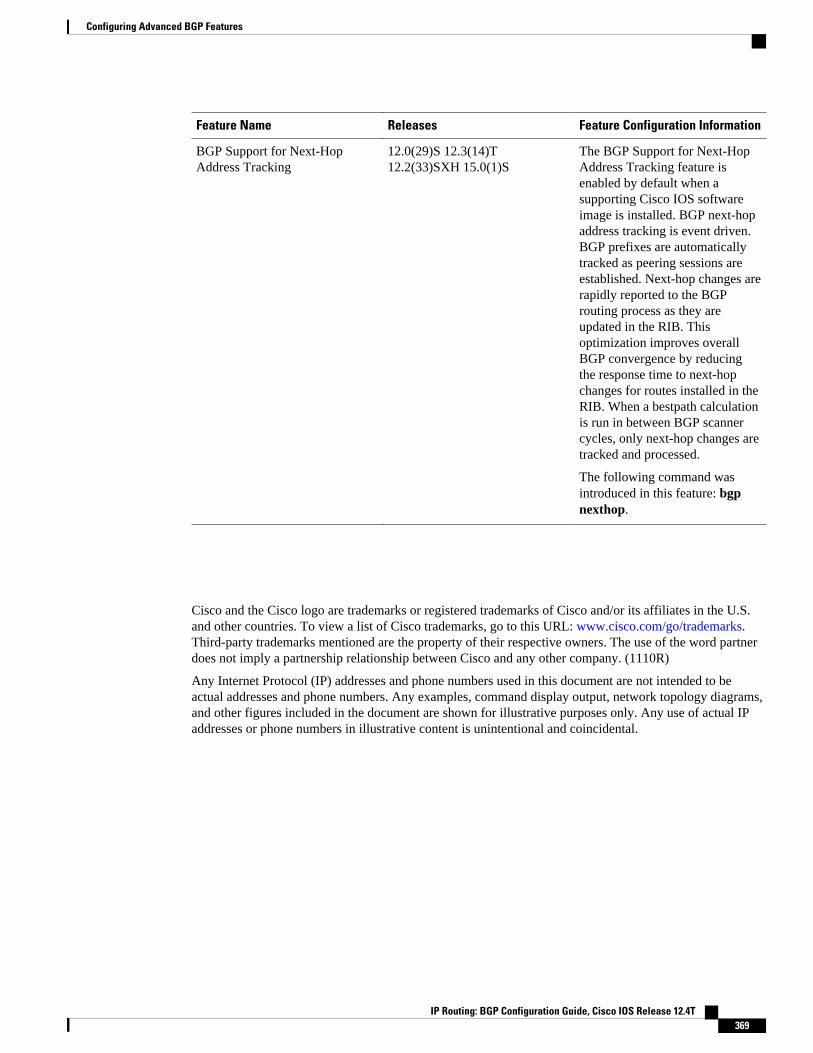
Feature Name Releases Feature Configuration Information
BGP Support for Next-HopAddress Tracking
12.0(29)S 12.3(14)T12.2(33)SXH 15.0(1)S
The BGP Support for Next-HopAddress Tracking feature isenabled by default when asupporting Cisco IOS softwareimage is installed. BGP next-hopaddress tracking is event driven.BGP prefixes are automaticallytracked as peering sessions areestablished. Next-hop changes arerapidly reported to the BGProuting process as they areupdated in the RIB. Thisoptimization improves overallBGP convergence by reducingthe response time to next-hopchanges for routes installed in theRIB. When a bestpath calculationis run in between BGP scannercycles, only next-hop changes aretracked and processed.
The following command wasintroduced in this feature: bgpnexthop.
Cisco and the Cisco logo are trademarks or registered trademarks of Cisco and/or its affiliates in the U.S.and other countries. To view a list of Cisco trademarks, go to this URL: www.cisco.com/go/trademarks.Third-party trademarks mentioned are the property of their respective owners. The use of the word partnerdoes not imply a partnership relationship between Cisco and any other company. (1110R)
Any Internet Protocol (IP) addresses and phone numbers used in this document are not intended to beactual addresses and phone numbers. Any examples, command display output, network topology diagrams,and other figures included in the document are shown for illustrative purposes only. Any use of actual IPaddresses or phone numbers in illustrative content is unintentional and coincidental.
Configuring Advanced BGP Features
IP Routing: BGP Configuration Guide, Cisco IOS Release 12.4T 369

Configuring BGP Support for MTR
IP Routing: BGP Configuration Guide, Cisco IOS Release 12.4T370