ipg-ui user’s guide
TRANSCRIPT

1SLVUAH9D–July 2015–Revised May 2016Submit Documentation Feedback
Copyright © 2015–2016, Texas Instruments Incorporated
IPG-UI User’s Guide
Microsoft, Windows are registered trademarks of Microsoft Corporation.All other trademarks are the property of their respective owners.
User's GuideSLVUAH9D–July 2015–Revised May 2016
IPG-UI User’s Guide
This document covers the usage of the Integrated Power Graphical User Interface (IPG-UI) software fromTexas Instruments.
Contents1 Introduction ................................................................................................................... 32 Supported Features ......................................................................................................... 33 Limitations .................................................................................................................... 34 Revisions...................................................................................................................... 45 Installation .................................................................................................................... 46 Launching the GUI........................................................................................................... 77 Landing Page................................................................................................................. 88 Views Overview ............................................................................................................ 129 Introduction View ........................................................................................................... 1410 Register Map View ........................................................................................................ 1911 Single Register ............................................................................................................. 3112 Register Controls ........................................................................................................... 3513 Device Controls............................................................................................................. 3814 Macros ....................................................................................................................... 3915 Adapter Controls ........................................................................................................... 4116 Status Bar .................................................................................................................. 4317 Quick Access Controls .................................................................................................... 4718 File Menu ................................................................................................................... 4819 GUI Settings ................................................................................................................ 4920 Report........................................................................................................................ 5021 Errors and Notifications ................................................................................................... 5122 Search ...................................................................................................................... 5323 Frequently Asked Questions (FAQ)...................................................................................... 55
List of Figures
1 Splash Screen................................................................................................................ 72 Landing Page................................................................................................................. 83 USB2ANY Selection......................................................................................................... 94 New Project Creation ...................................................................................................... 105 Opening an Existing Project .............................................................................................. 116 Recent Devices and Projects ............................................................................................. 127 Introduction View ........................................................................................................... 148 Device Description ......................................................................................................... 159 Device Block Diagram ..................................................................................................... 1610 Download Data Sheet ..................................................................................................... 1711 Get Started Button ......................................................................................................... 1812 Register Map View ......................................................................................................... 1913 Register Selection .......................................................................................................... 2014 Read/Write ALL............................................................................................................. 21

www.ti.com
2 SLVUAH9D–July 2015–Revised May 2016Submit Documentation Feedback
Copyright © 2015–2016, Texas Instruments Incorporated
IPG-UI User’s Guide
15 Read/Write Group .......................................................................................................... 2216 Single Register R/W ....................................................................................................... 2317 Bit Descriptions ............................................................................................................. 2418 Favorite Registers .......................................................................................................... 2519 Order By Category ......................................................................................................... 2620 Order By Favorite .......................................................................................................... 2721 I2C Address Control ........................................................................................................ 2822 Update Mode Control ...................................................................................................... 2923 AutoRead Control .......................................................................................................... 3024 Single Register View....................................................................................................... 3125 Single Register Mini-Map.................................................................................................. 3226 Single Register View With Unknown Multi-byte Register ............................................................. 3327 Generic I2C Access ........................................................................................................ 3428 Register Controls View .................................................................................................... 3529 Register Controls Auto Read ............................................................................................. 3630 Enable and Disable Register Map ....................................................................................... 3731 Device Controls............................................................................................................. 3832 Macros View ................................................................................................................ 3933 New Macro Creation Screen.............................................................................................. 4034 Adapter GPIO Controls .................................................................................................... 4235 Status Bar ................................................................................................................... 4336 Transaction History ........................................................................................................ 4437 Hardware Connected Status.............................................................................................. 4538 Changes Written Status ................................................................................................... 4639 Quick Access Controls..................................................................................................... 4740 File Menu .................................................................................................................... 4841 GUI Settings ................................................................................................................ 4942 Report........................................................................................................................ 5043 Error Notifications .......................................................................................................... 5144 Notifications ................................................................................................................. 5245 Search ....................................................................................................................... 5346 Search Controls ............................................................................................................ 54

www.ti.com Introduction
3SLVUAH9D–July 2015–Revised May 2016Submit Documentation Feedback
Copyright © 2015–2016, Texas Instruments Incorporated
IPG-UI User’s Guide
1 IntroductionThis software is created using web-based technologies such as Javascript, AngularJS, and Node-Webkit.This software requires using a USB2ANY adapter from Texas Instruments to communicate with the PMICEVM. The USB2ANY adapter provides a USB interface to the host PC for receiving commands and thencommunicates with the PMIC EVM using the I2C protocol.
The IPG-UI supports multiple devices with a single executable, which eliminates the need to installmultiple GUIs when working with more than one device.
For details on how to configure the EVM for the device being used, see the EVM user’s guide for thatPMIC in the product folder of TI.com.
2 Supported FeaturesThe IPG-UI supports the following features:• Supports multiple PMIC devices with a single GUI• Reading and Writing device registers• Setting register values using individual bits, hexadecimal values, or human-readable controls• Saving and Loading project files• Tracking previous devices and projects for easy access• Auto-reading registers at a variable polling interval• Write on change or manual write options• Searching registers and bits• Organizing registers by address, category, or favorites• USB2ANY communication with the EVM using I2C• Configuration of USB2ANY I2C protocols• Support for Microsoft® Windows® XP, Windows 7, Windows 8, Linux 32 and 64-bit (Ubuntu 14.04 LTS),
and Mac OSX 10.10.2• USB2ANY GPIO controls• Creation of Macros for repeated commands• Client and server model for communication with USB2ANY
3 LimitationsThe IPG-UI has the following limitations:• Windows 8 may require disabling the Enhanced Power Management for the USB2ANY device. If this is
enabled, the USB2ANY adapter will blink when it is connected and the IPG-UI application is notrunning. For details on how to disable this feature, see the Microsoft® Windows USB Core Team Bloghelp topic. The VID and PID of the USB2ANY adapter are 0x2047 and 0x0301.
• I2C is the only supported protocol to communicate with the device.• Only the USB2ANY adapter is supported. Other adapters such as USB-to-GPIO or EV2300 are not
supported. If you do not have a USB2ANY adapter, contact your local TI sales team to obtain one.• Requires USB2ANY firmware version 2.7.0.0. For information on updating the firmware, see the
Frequently Asked Questions (FAQ) section.• If the USB2ANY adapter is in a locked state (that is, the LED on the adapter is blinking), the IPG-UI
will freeze at the splash screen until the adapter has been unplugged. Reconnecting the adapter will bedetected and the GUI will then be able to access the USB2ANY device. A common reason for theUSB2ANY to get into a locked state is when the host PC is disconnected from the USB2ANY devicewhile the USB2ANY device remains powered. For example if the USB2ANY is connected through apowered USB hub which provides power to the USB2ANY and the host is disconnected from the hubthis issue can occur.

Revisions www.ti.com
4 SLVUAH9D–July 2015–Revised May 2016Submit Documentation Feedback
Copyright © 2015–2016, Texas Instruments Incorporated
IPG-UI User’s Guide
4 RevisionsThis section details the features added with each release of the IPG-UI.
1.0.0.0 This is the initial release containing the features listed in the supported features section.
1.0.0.2• Fixed issue with single register read to configure the adapter protocol for unknown register groups• Added support for Linux and Mac OSX installers• Fix I2C address list for 10-bit addresses
2.0.0.0 Added support for the following features:• Updated node-webkit version to 0.12.3• Added support for Macros to enable replaying common command sequences• Added support for Device Controls to configure device level settings• Added advanced controls to allow the GUI to reflect the device status more accurately• Additional device support files added to the base installation• Preserve selections when switching between views• Enhanced transaction history to show pre-commands and post-commands as well as which commands
were sent as a single block• Added a mini register map to the Register Controls view• Added confirmation of write of unknown values• Added autosave GUI option• Updated styling of GUI elements
2.5.0.0 Added support for the following features:• Allow Macros to use “unknown” registers• Added support to run Macros as a specified interval• Macros can now run groups of commands as a single transaction• Added Auto-Read controls to register controls• Added support to set custom intervals for auto-read per register• Added ability to drag and drop register and device controls to change order• Improvements to transaction history styling• Added sub-category support for register and device controls• Added ability to group like controls into a single display box to save space• Added dump register report support• Added support for Multi-byte registers• Screen captures in this user's guide have been updated for new features but some may vary slightly in
appearance
5 Installation
5.1 WindowsThe IPG-UI is delivered as a Windows installer and supports the following features:• Selection of installation path. TI recommends using the default installation path.• Optional creation of a desktop shortcut to launch the GUI• Creation of a Start Menu shortcut in the Texas Instruments directory• Option to launch the GUI after installation• Uninstaller which can be run through the Windows Programs and Features page in the Control Panel

www.ti.com Installation
5SLVUAH9D–July 2015–Revised May 2016Submit Documentation Feedback
Copyright © 2015–2016, Texas Instruments Incorporated
IPG-UI User’s Guide
After installation the IPG-UI will be installed by default into the C:\Program Files (x86)\TexasInstruments\IPGUI- <version>/IPG-UI directory. The executable name is nw.exe. In this directory you canalso find the software manifest for the IPG-UI which details the software components used and theircorresponding licenses.
5.2 LinuxThe IPG-UI is delivered as a .run installer for Linux and supports the following features:• Selection of installation path. TI recommends using the default installation path.• Optional creation of a desktop shortcut to launch the GUI• Prompt for sudo password to configure the host Linux system to access the USB2ANY adapter• Option to launch the GUI after installation• An uninstaller program in the installation directory for removing the GUI

Installation www.ti.com
6 SLVUAH9D–July 2015–Revised May 2016Submit Documentation Feedback
Copyright © 2015–2016, Texas Instruments Incorporated
IPG-UI User’s Guide
In order to properly install the GUI the following pre-requisites should be met:1. The user should have sudo permissions. In order to access the USB2ANY adapter and run the GUI
udev rules and symlinks must be created along with a usb2any group. The user will be promptedduring installation to provide their sudo password. If the password is incorrect or the user does nothave sudo permissions they can re-run the IPG-UI-linux-setup.sh script installed in the installationdirectory to finish the setup at a later time.
2. The GUI installer should be marked as executable3. For Ubuntu 14.04, the latest version of node-webkit and node-hid require GCC and libstdc 5.0 libraries.
During the setup script execution, the following commands will be attempted to download andconfigure these software packages. This download and configuration will take additional time duringinstallation.• sudo add-apt-repository ppa:ubuntu-toolchain-r/test• sudo apt-get update• sudo apt-get install g++-5
If you are installing this GUI on a system behind a firewall you must export the http_proxy andhttps_proxy environment variables before installation in order for these commands to work. If this is notdone then the libraries will not be updated and the GUI will not find the USB2ANY adapter. The usercan then either run these commands manually or export the proxy configuration and re-run the IPG-UI-linux-setup.sh script.
As mentioned in the pre-requisites during installation the user will be prompted to provide the sudopassword in order to finish configuration on their system. The same will also occur during uninstallation ofthe GUI.
After installation the IPG-UI will be installed by default into the user’s home directory inTexas_Instruments/IPGUI-<version>/IPG-UI as IPG-UI.
NOTE: It is required that the user logout and login again for the changes to the udev rules andgroups to take effect. Without this the GUI will be unable to find the USB2ANY adapter.
NOTE: You may need to unplug and reconnect the USB2ANY adapter after installation for the newudev rule to take affect. The detection process can take a few seconds before the USB2ANYadapter is detected.
5.3 OSXThe IPG-UI is delivered as an .app.zip installer for OSX and supports the following features:• Selection of installation path. TI recommends using the default installation path.• Option to launch the GUI after installation• An uninstaller program in the installation directory for removing the GUI
In order to install on OSX the user should double-click on the .app.zip file to extract the applicationinstaller. Once the application installer is extracted the user can double-click it and the installation willbegin. The IPG-UI will automatically be added to the list of applications in the application launcher under aTexas_Instruments group.
After installation the IPG-UI will be installed by default into the /Applications/Texas_Instruments/IPGUI-<version>/IPG-UI directory as IPG-UI. This is an application directory and can be run by double-clicking itin the finder.
www.ti.com Launching the GUI
7SLVUAH9D–July 2015–Revised May 2016Submit Documentation Feedback
Copyright © 2015–2016, Texas Instruments Incorporated
IPG-UI User’s Guide
6 Launching the GUIThe easiest method to run the IPG-UI is to use the desktop shortcut if it was created. If no desktopshortcut was created then you can browse to the installation directory referred to above for your OS anddouble-click the executable. For Windows systems there is also a shortcut created in the Start Menu in theTexas Instruments directory that can be used.
When the GUI begins execution, the GUI extracts its components to a temporary directory on the host PCand launches the Node-Webkit browser using those components to render the GUI web page.
It should be noted that any changes made to files inside of the temporary directory will be lost when theGUI exits. The default project save and open paths point to the following directories based on the hostOS:
Windows: user’s <My Documents>/Texas Instruments/IPG-UI directory
Linux: <user's home>/Documents/.Texas_Instruments which is a hidden directory in the user’s homedirectory
OSX: <user's home>/Documents/.Texas_Instruments which is a hidden directory in the user’s homedirectory
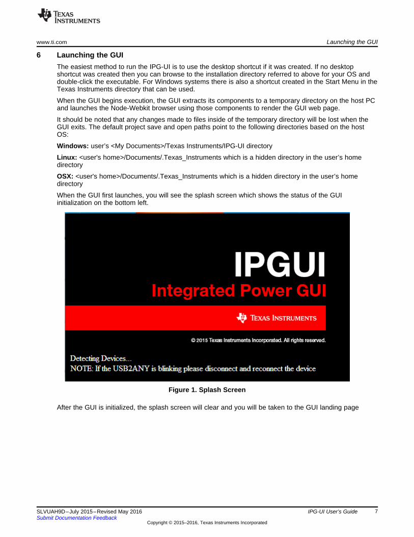
When the GUI first launches, you will see the splash screen which shows the status of the GUIinitialization on the bottom left.
Figure 1. Splash Screen
After the GUI is initialized, the splash screen will clear and you will be taken to the GUI landing page

Landing Page www.ti.com
8 SLVUAH9D–July 2015–Revised May 2016Submit Documentation Feedback
Copyright © 2015–2016, Texas Instruments Incorporated
IPG-UI User’s Guide
7 Landing PageAfter the splash screen has cleared the GUI will show the device landing page. This page is used to allowthe user to select which device to work with and the USB2ANY adapter to use. The following sectionsdetail the options available on the landing page. After a device or project has been selected on the landingpage, the GUI title bar will update with the device name.
Figure 2. Landing Page

www.ti.com Landing Page
9SLVUAH9D–July 2015–Revised May 2016Submit Documentation Feedback
Copyright © 2015–2016, Texas Instruments Incorporated
IPG-UI User’s Guide
7.1 Select USB2ANY AdapterIn the case of multiple USB2ANY adapters being connected the user can select which one to use from thedropdown box at the bottom of the landing page. See the screen capture in Figure 3.
Figure 3. USB2ANY Selection

Landing Page www.ti.com
10 SLVUAH9D–July 2015–Revised May 2016Submit Documentation Feedback
Copyright © 2015–2016, Texas Instruments Incorporated
IPG-UI User’s Guide
7.2 Create a New ProjectIn order to create a new project for a device the user can select from the following options:
Figure 4. New Project Creation
1. Select Device – This option will give the user a list of pre-packaged devices supported by the IPG-UIas a dropdown. Once the device has been selected the Create Project button should be clicked tocreate the project and open the device introduction page for the selected device.
2. Load Device Information from File – This option allows the user to load a stand-alone deviceconfiguration file that is not part of the pre-packaged list and create a project. Clicking the Select Filebutton will open a file explorer dialog where the user can browse to the file they wish to create aproject from.
It should be noted that creating a project works with device description files and not with existing projectfiles. Attempting to open an existing project file will give trigger an error notification. To open and existingproject see the next section.
NOTE: The refresh button can be used to scan for additional device support files that have beeninstalled while the GUI is still running and add them to the list of available devices.

www.ti.com Landing Page
11SLVUAH9D–July 2015–Revised May 2016Submit Documentation Feedback
Copyright © 2015–2016, Texas Instruments Incorporated
IPG-UI User’s Guide
7.3 Loading an Existing ProjectTo open an existing project the user should use the Select File button in the Open Project section of thelanding page as shown below. Clicking this button will open a file explorer dialog where the user canbrowse to the project file they wish to load.
Figure 5. Opening an Existing Project
Attempting to open a device description file using the Open Project feature will display an error on thescreen.

Landing Page www.ti.com
12 SLVUAH9D–July 2015–Revised May 2016Submit Documentation Feedback
Copyright © 2015–2016, Texas Instruments Incorporated
IPG-UI User’s Guide
7.4 Recent Projects and DevicesFor both Create New Project and Open Project the most recent three files opened are listed to the rightof the selection area. Clicking one of these entries will re-open that file and provides a shortcut method foropening previous devices and files without requiring browsing the user file system. Each list of recentdevices can be cleared using the Clear history link for that section.
Figure 6. Recent Devices and Projects
Once you have either created a new project or opened an existing project you will be taken to theintroduction view for that device. This will be covered in later sections.
8 Views OverviewThis section provides an overview of the views available through the navigation pane on the left side ofthe GUI after a device or project file has been selected. For details of operations available in each viewplease see the following sections in this guide.
8.1 IntroductionThe Introduction view provides the user with a description of the device, a block diagram of the device,and a link to the online device data sheet. Clicking the Get Started button will take the user to theRegister Map view where they can begin to interact with the device.
8.2 Register MapThe Register Map view provides the user with a representation of the device register map where valuescan be read or written. If a device is not connected with a USB2ANY adapter the user is still able to makemodifications to the register map and save them as a project to enable writing them to the device at a latertime when the hardware is connected.

www.ti.com Views Overview
13SLVUAH9D–July 2015–Revised May 2016Submit Documentation Feedback
Copyright © 2015–2016, Texas Instruments Incorporated
IPG-UI User’s Guide
8.3 Register ControlsThe Register Controls view shows all of the human readable controls defined for the device organized bycategories. Changes to the controls will automatically set the corresponding bits in the register map. Thisis provided to make it easier to configure the device without requiring looking up bit settings in the datasheet.
8.4 Single RegisterThe Single Register view allows the user to work with only a single register at a time. This is particularlyuseful when using a device such as the blank I2C device which will allow the user to read and write to anyregister on any I2C bus. If a register is a known register for the device selected then the information forthat register will be displayed as well.
8.5 Adapter ControlsThe Adapter Controls view is used to configure the USB2ANY adapter settings such as pull-ups, I2Caddress length, and I2C address protocol.
8.6 Device ControlsThe Device Controls view shows controls that are not tied to a specific register but rather are intended tobe used to control the EVM or device. These controls can be items such as whether to enable autopassword setting, or to run particular command sequences to enable some functionality of the Device.This view will only be available if the selected device has Device Controls declared.
8.7 MacrosThe Macros view is always available and will show the user any existing macros that are already declaredfor the device selected. Macros are sequences of commands that can be re-run with a single button clickto help make complex or frequently-performed operations easier. Even when no pre-defined macros exist,the Macros view can be used to allow the user to create custom macros from the transaction history ofcommands they have sent to the device.

Introduction View www.ti.com
14 SLVUAH9D–July 2015–Revised May 2016Submit Documentation Feedback
Copyright © 2015–2016, Texas Instruments Incorporated
IPG-UI User’s Guide
9 Introduction ViewThis section will cover the introduction view for a device and the features available.
Figure 7. Introduction View

www.ti.com Introduction View
15SLVUAH9D–July 2015–Revised May 2016Submit Documentation Feedback
Copyright © 2015–2016, Texas Instruments Incorporated
IPG-UI User’s Guide
9.1 Device DescriptionThe device description gives an overview of the device features and uses. It is presented as a paragraphof text at the top of the introduction view.
Figure 8. Device Description

Introduction View www.ti.com
16 SLVUAH9D–July 2015–Revised May 2016Submit Documentation Feedback
Copyright © 2015–2016, Texas Instruments Incorporated
IPG-UI User’s Guide
9.2 Device Block DiagramThe device block diagram will be shown at the bottom of the introduction view. If the block diagram scrollsoff the screen the user can scroll or resize the GUI to see the rest of the image.
Figure 9. Device Block Diagram
www.ti.com Introduction View
17SLVUAH9D–July 2015–Revised May 2016Submit Documentation Feedback
Copyright © 2015–2016, Texas Instruments Incorporated
IPG-UI User’s Guide
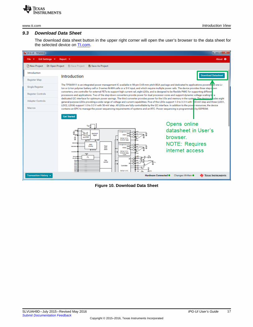
9.3 Download Data SheetThe download data sheet button in the upper right corner will open the user’s browser to the data sheet forthe selected device on TI.com.
Figure 10. Download Data Sheet

Introduction View www.ti.com
18 SLVUAH9D–July 2015–Revised May 2016Submit Documentation Feedback
Copyright © 2015–2016, Texas Instruments Incorporated
IPG-UI User’s Guide
9.4 Get StartedThe Get Started button located between the device description and device block diagram will take theuser to the register map for that device.
Figure 11. Get Started Button

www.ti.com Register Map View
19SLVUAH9D–July 2015–Revised May 2016Submit Documentation Feedback
Copyright © 2015–2016, Texas Instruments Incorporated
IPG-UI User’s Guide
10 Register Map ViewThis section will cover the register map view and the available operations and features. This is the defaultview after the Introduction view.
Figure 12. Register Map View
The register map can have multiple tabs with each tab representing a bank of registers. Within each tab isa scrollable table of registers that the user can interact with.

Register Map View www.ti.com
20 SLVUAH9D–July 2015–Revised May 2016Submit Documentation Feedback
Copyright © 2015–2016, Texas Instruments Incorporated
IPG-UI User’s Guide
10.1 Selecting a RegisterWhen the user clicks on a register the register will be marked as active by having the background for theregister row turn to gray. This has the additional effect of populating the register description section to theright side of the GUI.
Figure 13. Register Selection
The register description area provides information about the selected register as well as the definedregister controls. These controls can be used to modify the bits in the register as described in latersections.
When hardware is connected and any of the following actions are performed the GUI will automaticallyread the register value:1. Any bit in the register bits is clicked2. Any control in the register group is changed3. The user selects the Value field and then moves focus elsewhere in the GUI (blur operation)
Additional register read controls are detailed in the following section.
www.ti.com Register Map View
21SLVUAH9D–July 2015–Revised May 2016Submit Documentation Feedback
Copyright © 2015–2016, Texas Instruments Incorporated
IPG-UI User’s Guide
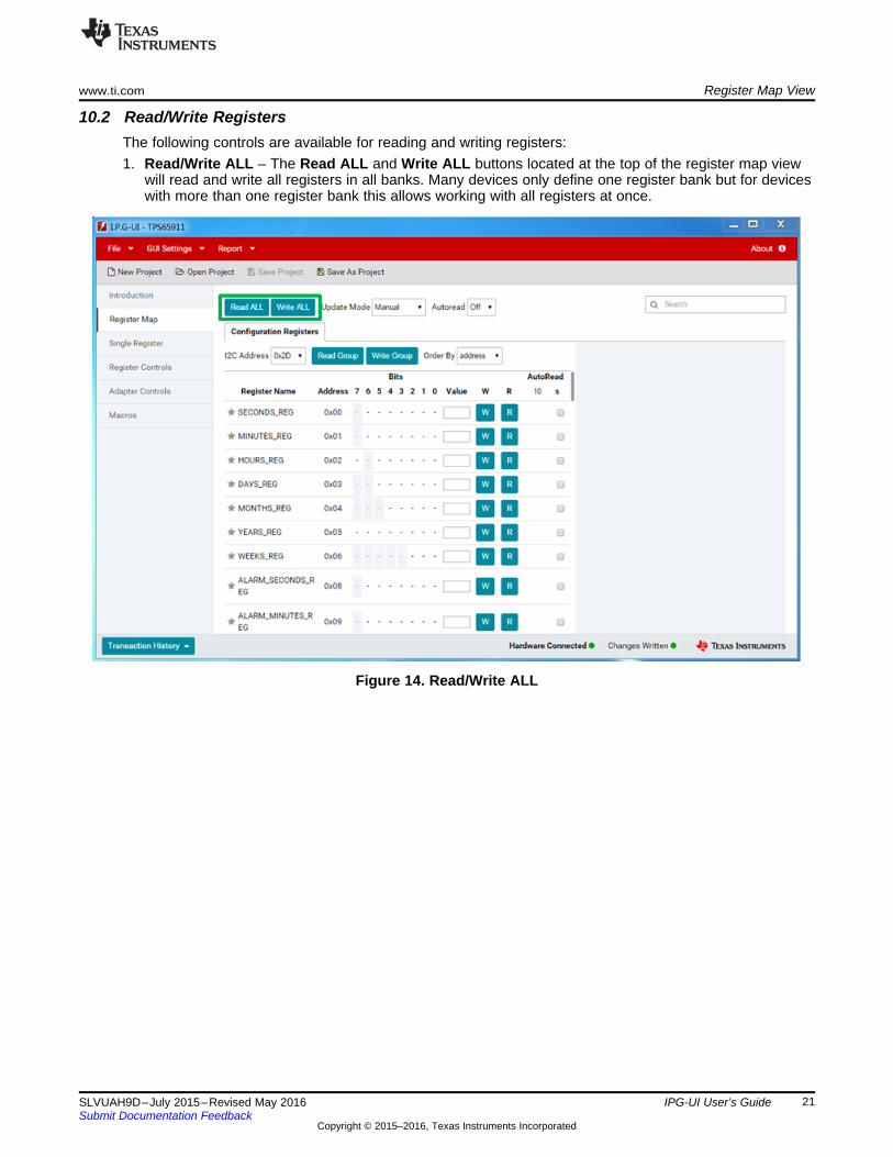
10.2 Read/Write RegistersThe following controls are available for reading and writing registers:1. Read/Write ALL – The Read ALL and Write ALL buttons located at the top of the register map view
will read and write all registers in all banks. Many devices only define one register bank but for deviceswith more than one register bank this allows working with all registers at once.
Figure 14. Read/Write ALL

Register Map View www.ti.com
22 SLVUAH9D–July 2015–Revised May 2016Submit Documentation Feedback
Copyright © 2015–2016, Texas Instruments Incorporated
IPG-UI User’s Guide
2. Read/Write Group – The Read Group and Write Group buttons located inside of each bank ofregisters enable the user to read or write only that bank of registers. All registers in that bank will beread or written when this button is clicked.
Figure 15. Read/Write Group
www.ti.com Register Map View
23SLVUAH9D–July 2015–Revised May 2016Submit Documentation Feedback
Copyright © 2015–2016, Texas Instruments Incorporated
IPG-UI User’s Guide
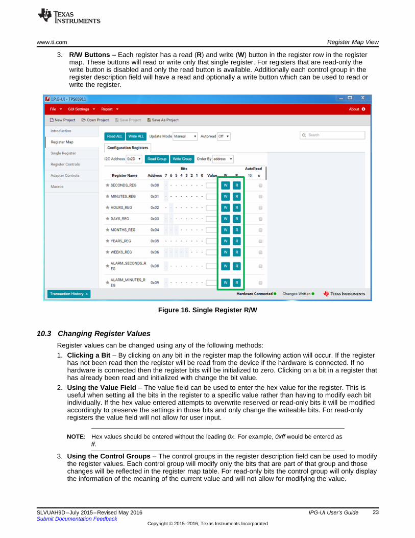
3. R/W Buttons – Each register has a read (R) and write (W) button in the register row in the registermap. These buttons will read or write only that single register. For registers that are read-only thewrite button is disabled and only the read button is available. Additionally each control group in theregister description field will have a read and optionally a write button which can be used to read orwrite the register.
Figure 16. Single Register R/W
10.3 Changing Register ValuesRegister values can be changed using any of the following methods:1. Clicking a Bit – By clicking on any bit in the register map the following action will occur. If the register
has not been read then the register will be read from the device if the hardware is connected. If nohardware is connected then the register bits will be initialized to zero. Clicking on a bit in a register thathas already been read and initialized with change the bit value.
2. Using the Value Field – The value field can be used to enter the hex value for the register. This isuseful when setting all the bits in the register to a specific value rather than having to modify each bitindividually. If the hex value entered attempts to overwrite reserved or read-only bits it will be modifiedaccordingly to preserve the settings in those bits and only change the writeable bits. For read-onlyregisters the value field will not allow for user input.
NOTE: Hex values should be entered without the leading 0x. For example, 0xff would be entered asff.
3. Using the Control Groups – The control groups in the register description field can be used to modifythe register values. Each control group will modify only the bits that are part of that group and thosechanges will be reflected in the register map table. For read-only bits the control group will only displaythe information of the meaning of the current value and will not allow for modifying the value.

Register Map View www.ti.com
24 SLVUAH9D–July 2015–Revised May 2016Submit Documentation Feedback
Copyright © 2015–2016, Texas Instruments Incorporated
IPG-UI User’s Guide
10.4 Coloring/HighlightingThe following colors are used in the register map and register description fields to indicate status:• Gray Register Row – This is used to indicate which register is selected. The selected register will
have its description populated in the register description field.• Yellow – This is used to show highlighted bits. The use cases for highlighting bits are:
– Moving the mouse over a bit will highlight all the bits in the group that bit belongs to, if any. Furtherif the register is active then the corresponding control group in the register description will behighlighted as well.
– Moving the mouse over a control group in the register description will highlight all bits that are partof that group in the register map table.
• Orange – This is used to show the current search result• Blue – When a bit is changed from the last value read the background for the bit and the bit text will
turn blue to indicate a change. Either reading the register again or writing the register will clear thiscolor change. When a register is first read the default comparison value is zero. This means that anyvalues of 1 read from the device will be marked as changed so that the user can see the shift in bitvalue.
• Light Blue Bit – A light blue bit is a read-only bit. Clicking on this bit will cause a register read for anuninitialized register, but any further clicks will not perform any action. The mouse icon will changewhen it is over a read-only bit for the selected register to indicate that the bit cannot be clicked.
10.5 HoveringHovering the mouse over any bit in the register map will display information about the register and that bitin the register to the user. This enables the user to find out more information about a particular bit.
Figure 17. Bit Descriptions

www.ti.com Register Map View
25SLVUAH9D–July 2015–Revised May 2016Submit Documentation Feedback
Copyright © 2015–2016, Texas Instruments Incorporated
IPG-UI User’s Guide
10.6 Marking a Register as FavoriteThe star icon at the left of each register row enables the user to mark the register as a favorite register.Marking a register as favorite will change the star to yellow while non-favorite registers will have a graystar. It is possible to sort the register map to bring favorite registers to the top of the map as detailed in theOrder By section.
Figure 18. Favorite Registers

Register Map View www.ti.com
26 SLVUAH9D–July 2015–Revised May 2016Submit Documentation Feedback
Copyright © 2015–2016, Texas Instruments Incorporated
IPG-UI User’s Guide
10.7 Order ByThe Order By control determines how the register map is sorted. By default the registers are sorted byaddress from lowest to highest. However the use can also select to order the registers by the following:• Category – This will group registers with the same category together. This is useful to help bring all
registers related to a similar topic together.
Figure 19. Order By Category

www.ti.com Register Map View
27SLVUAH9D–July 2015–Revised May 2016Submit Documentation Feedback
Copyright © 2015–2016, Texas Instruments Incorporated
IPG-UI User’s Guide
• Favorite – This will move all registers that have been marked as favorite to the top of the register map.All other registers will be listed below the favorite registers. This is useful when the user wishes tointeract with a set of registers repeatedly that are scattered throughout the register map. By movingthese registers to the top of the list the user can avoid having to scroll the register map betweenregisters.
Figure 20. Order By Favorite
Register Map View www.ti.com
28 SLVUAH9D–July 2015–Revised May 2016Submit Documentation Feedback
Copyright © 2015–2016, Texas Instruments Incorporated
IPG-UI User’s Guide
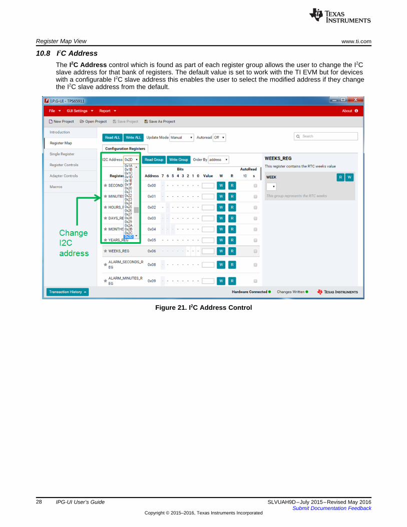
10.8 I2C AddressThe I2C Address control which is found as part of each register group allows the user to change the I2Cslave address for that bank of registers. The default value is set to work with the TI EVM but for deviceswith a configurable I2C slave address this enables the user to select the modified address if they changethe I2C slave address from the default.
Figure 21. I2C Address Control

www.ti.com Register Map View
29SLVUAH9D–July 2015–Revised May 2016Submit Documentation Feedback
Copyright © 2015–2016, Texas Instruments Incorporated
IPG-UI User’s Guide
10.9 Update ModeThe Update Mode control found at the top of the register map view can be used to configure when writeoperations are performed. There are two settings available:• Manual – This is the default mode and means that a write will only occur when the user clicks one of
the write buttons as detailed in the previous sections.• Immediate – In this mode a write will be performed any time a register value is changed using any of
the methods detailed in the previous sections. This is not the default mode as it should be used withcaution. Because the write occurs any time the register value is changed it is possible to put theregister in to an undesired state when clicking on bits to change their value. It is recommended in thismode that the user use the control groups or the value field to set the entire value of the register orregister bit groups if interim values are not desired.
Figure 22. Update Mode Control

Register Map View www.ti.com
30 SLVUAH9D–July 2015–Revised May 2016Submit Documentation Feedback
Copyright © 2015–2016, Texas Instruments Incorporated
IPG-UI User’s Guide
10.10 AutoreadIt is possible to set registers to be automatically read at a given interval. This is useful for operations suchas polling status registers of the device. There are two parts to this control in the register map.1. To the right of each register in the register map there is a checkbox in the AutoRead column. Checking
this box will mark the register to be read automatically when the polling interval is set as described inthe next item. It is also possible to mark all registers to be automatically read by selecting thecheckbox in the table header.
2. In the upper area of the register map view there is a drop-down with the label Autoread. This drop-down controls the polling interval for the autoread functionality. When the interval is set to any otherthan Off all registers that have the autoread checkbox marked will be read after each polling interval.
Figure 23. AutoRead Control
To stop automatically reading registers either return the polling interval to Off or uncheck the register’sautoread checkbox.

www.ti.com Single Register
31SLVUAH9D–July 2015–Revised May 2016Submit Documentation Feedback
Copyright © 2015–2016, Texas Instruments Incorporated
IPG-UI User’s Guide
11 Single RegisterThe single register view allows to user to focus on an individual register. It also enables some additionalregister controls that will be detailed in this section.
Figure 24. Single Register View

Single Register www.ti.com
32 SLVUAH9D–July 2015–Revised May 2016Submit Documentation Feedback
Copyright © 2015–2016, Texas Instruments Incorporated
IPG-UI User’s Guide
11.1 Register Mini-MapThe register mini-map shows a consistent look and feel to match with the register map view for eachregister. The controls are the same for this mini-map except that autoread and favorite selection aredisabled. The register description is also present on the right side to be consistent with the register mapview.
Figure 25. Single Register Mini-Map
11.2 Setting the Register AddressWhen the Reg Address and/or I2C Address field is updated the single register view will be updated toshow one of the following options:• Known Register – If the register address is a known register for the selected I2C Slave address then
the register mini-map will show that register and register description, including any changes that weremade in the register map view. For known registers the Big Endian Addressing and Reg Width valuecannot be changed.
• Unknown Register – If the register address is an unknown register for the selected I2C Slave addressthen a generic register mini-map will be created. This allows working with registers that may not havebeen defined yet. Additionally it is possible for unknown registers to change the endianness of theregister address which is used for registers with addresses greater than 8 bits as well as to adjust theregister width.
11.3 Big Endian AddressingBig Endian Addressing is used for registers with an address greater than 8 bits (for example 16-bitaddressing). This allows the user to set the endianness of the address so that they can enter the registeraddress as normal, that is, 0x0001, and the software will take care of sending this over the I2C bus as0x0100.

www.ti.com Single Register
33SLVUAH9D–July 2015–Revised May 2016Submit Documentation Feedback
Copyright © 2015–2016, Texas Instruments Incorporated
IPG-UI User’s Guide
11.4 Reg WidthThe Reg Width control can be used to change the number of bits in any unknown register. This allowsprogramming registers that are wider than 8 bits.
Figure 26. Single Register View With Unknown Multi-byte Register
11.5 Generic I2C AccessThe Single Register view can be used for generic I2C access in the following manner. When creating anew project from a device file on the landing page the user can select the Blank-I2C-7bit device to createthe project. Because this device has no known registers all registers on any I2C slave address can beconfigured for endianness and register width. The user can then use the read and write buttons to readand write the register.

Single Register www.ti.com
34 SLVUAH9D–July 2015–Revised May 2016Submit Documentation Feedback
Copyright © 2015–2016, Texas Instruments Incorporated
IPG-UI User’s Guide
Figure 27. Generic I2C Access

www.ti.com Register Controls
35SLVUAH9D–July 2015–Revised May 2016Submit Documentation Feedback
Copyright © 2015–2016, Texas Instruments Incorporated
IPG-UI User’s Guide
12 Register ControlsThe Register Controls view enables the user to view all of the control groups sorted by category. Thisgives the user the ability to access the human-readable controls without having to select betweenregisters on the register map or search the data sheet to find out what registers contain a particularcategory of controls.
NOTE: The controls within a category or sub-category can be reordered by dragging and dropping,for convenience.
Figure 28. Register Controls View
Selecting a category tab at the top of the view will bring up all of the control groups that are part of thatcategory. Interacting with the controls is the same as using the control groups in the register description ascovered previously. All changes made in the register controls view will be visible in the register map view.

Register Controls www.ti.com
36 SLVUAH9D–July 2015–Revised May 2016Submit Documentation Feedback
Copyright © 2015–2016, Texas Instruments Incorporated
IPG-UI User’s Guide
12.1 Register Controls Auto ReadIt is possible to control the auto read settings from the Register Controls view as well. The checkboxesfound inside of the register controls tabs and groups will enable the auto read for the various groups andall the groups within a category. Custom auto-read intervals can be specified in the text box next to theauto-read enable checkbox
Figure 29. Register Controls Auto Read
NOTE: The read operation is done at a register level so selecting auto read for a group will alsoselect auto read for all other groups contained in that register.
12.2 Enabling and Disabling Register MapThe Display Register Map checkbox can be used to enable or disable the register map view to the right ofthe screen. Disabling the register map provides additional space for displaying register controls.

www.ti.com Register Controls
37SLVUAH9D–July 2015–Revised May 2016Submit Documentation Feedback
Copyright © 2015–2016, Texas Instruments Incorporated
IPG-UI User’s Guide
Figure 30. Enable and Disable Register Map
Device Controls www.ti.com
38 SLVUAH9D–July 2015–Revised May 2016Submit Documentation Feedback
Copyright © 2015–2016, Texas Instruments Incorporated
IPG-UI User’s Guide
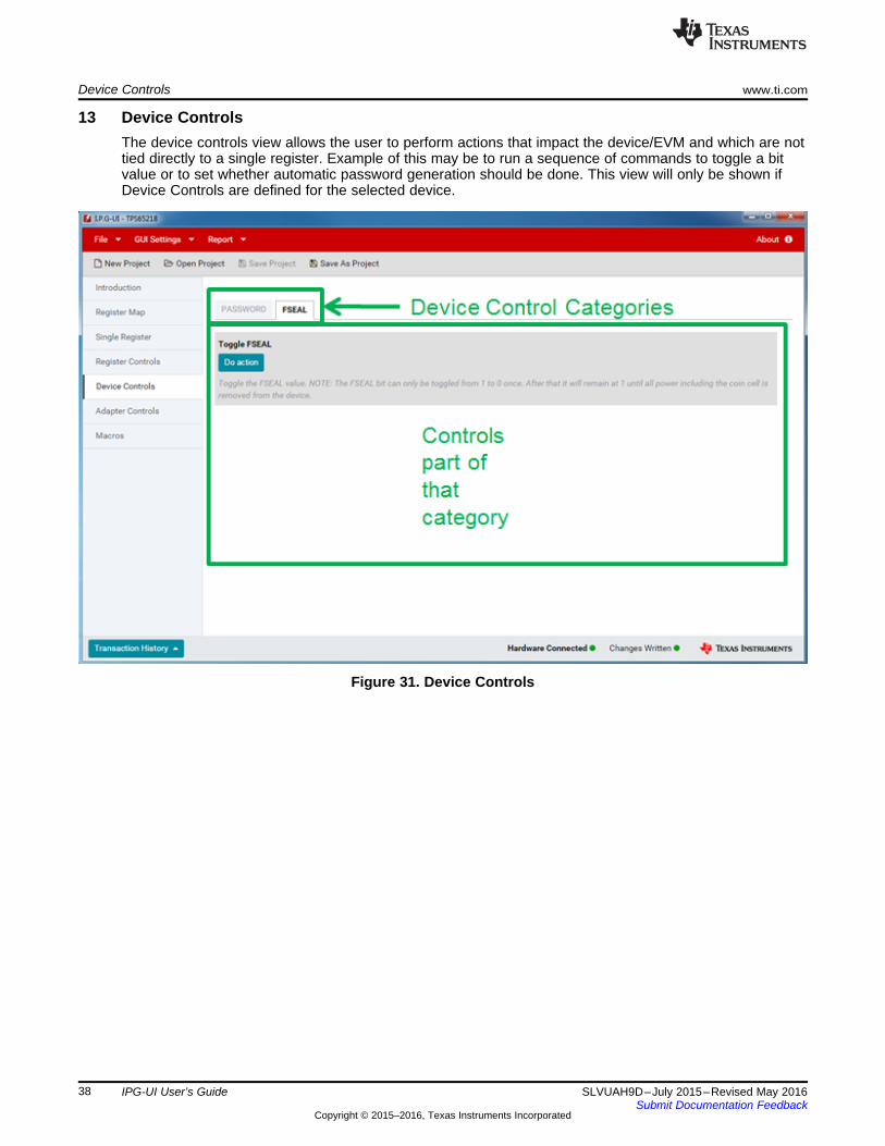
13 Device ControlsThe device controls view allows the user to perform actions that impact the device/EVM and which are nottied directly to a single register. Example of this may be to run a sequence of commands to toggle a bitvalue or to set whether automatic password generation should be done. This view will only be shown ifDevice Controls are defined for the selected device.
Figure 31. Device Controls

www.ti.com Macros
39SLVUAH9D–July 2015–Revised May 2016Submit Documentation Feedback
Copyright © 2015–2016, Texas Instruments Incorporated
IPG-UI User’s Guide
14 MacrosThe Macros view allows the user to run any of the pre-defined macros for the device (if any) or to createnew macros from the transaction history to save commonly-repeated command sequences. The optionsavailable are:1. Run the macro to execute the sequence of commands2. Edit/View the macro to adjust what commands are being run. Edit is only available for user-created
macros. Pre-defined macros only allow viewing the commands.3. Clone the macro to give a starting point for defining a new macro4. Delete the macro. This is only available for user-defined macros. Pre-defined macros cannot be
deleted.5. Enable running a macro at a given interval.
Figure 32. Macros View

Macros www.ti.com
40 SLVUAH9D–July 2015–Revised May 2016Submit Documentation Feedback
Copyright © 2015–2016, Texas Instruments Incorporated
IPG-UI User’s Guide
14.1 Creating a New MacroClicking the New Macro button takes the user to the macro creation screen. Here the user has the abilityto:
Figure 33. New Macro Creation Screen
1. Assign a name and description to the macro2. Choose which category to add the macro to or create a new category3. Select items from the transaction history to be added to the macro4. Determine the order of the commands to run in the macro by dragging and dropping them into the
desired order5. Save the macro to be run again later
The back button can be used to return to the Macros view without saving the macro.
NOTE: Not all items in the transaction history are available to be added to macros. When atransaction item is created by the GUI automatically, this item will not be selectable formacros. An example of this is if automatically generating the password requires writing to apassword register before writing the register the user selected, then the write of the user-selected register will be available for the macro, but the auto-generated command to writethe password register will not. This is done on purpose as selecting the write of the registerwill regenerate the auto write command so there is no need for the user to add that to themacro directly.
NOTE: Items run as part of a single bulk transaction are saved in the macro as a single transaction.If you desire to split up the bulk transaction you must run the operations individually and thencreate the macro.

www.ti.com Macros
41SLVUAH9D–July 2015–Revised May 2016Submit Documentation Feedback
Copyright © 2015–2016, Texas Instruments Incorporated
IPG-UI User’s Guide
14.2 Transaction HistoryThe Transaction History lists all of the commands sent to and from the device as well as any devicecontrol actions that have been run. The commands are grouped together to show which were performedas part of a single operation. Errors are also displayed in the transaction history. Clicking on thetransaction history will expand it so that the user may scroll through the history of commands and errors.
With the addition of advanced controls, it is possible for pre and post operations to be performedautomatically for the user. To differentiate these from normal commands, they are tabbed over to the right.Items that are tabbed to the right below the primary command are run before the primary command. Itemsthat are tabbed to the right above the primary command are run after the primary command. These itemswill not be selectable in the Macros view as they will be run automatically when the user selects theprimary command for the macro.
15 Adapter ControlsThe Adapter Controls allow the user to change the USB2ANY adapter configuration for their device. Thedefault values are assigned by the device description but can be overridden by the adapter controls.However, the default values are set to work for the EVM from TI and should not need modification. Thefollowing controls are available to the user:
15.1 Protocol Controls•
– I2C Address – This control allows the user to select whether to use 7-bit or 10-bit I2C slaveaddressing. For example when using the single register view with the blank device as coveredpreviously this would allow the user to communicate with devices that use a 10-bit I2C slaveaddress rather than the default 7-bit addressing.
– 3.3V pullup – This enables the 3.3-V pull-ups on the USB2ANY adapter for devices that do nothave a pull-up already on the board.
– 5V pullup – This enables the 5-V pull-ups on the USB2ANY for devices that do not have a pull-upalready on the board.
– I2C Speed – This allows the user to change the I2C bus speed for the device. The available speedsare 10, 100, and 400 kbps and are determined by the adapter hardware, not by the PMIC.
– Protocol – This allows the user to choose the I2C protocol to use. Some devices do not support therepeated start protocol for operations like a register read. Instead they require a stop/start protocolto be used.
– Transfer Mode – This allows the user to specify whether block mode transfers should be usedwhen communicating with the device. When Block mode transfers are used the IPG-UI willconsolidate contiguous registers into a single read or write (up to the USB2ANY limit) and transmitthem with a single command. In Single mode each register is read or written one at a time. Not alldevices support block mode and single mode must be used.

Adapter Controls www.ti.com
42 SLVUAH9D–July 2015–Revised May 2016Submit Documentation Feedback
Copyright © 2015–2016, Texas Instruments Incorporated
IPG-UI User’s Guide
15.2 GPIO ControlsFigure 34 illustrates and highlights features of the adapter GPIO controls window.
Figure 34. Adapter GPIO Controls
1. Read State/Write State – Read or write the current state of the GPIO2. Polling – Poll selected GPIOs at a specified interval3. Update Mode – Set whether to update the GPIO config and state values on charge or manually4. Config – Set the GPIO configuration as either an input or output5. State – Set the GPIO high or low state. For input GPIOs this is a read-only control. For output GPIOs
this is a toggle control. Green indicates high.6. Poll – Set the GPIO as part of the list to be polled if the Polling control is set
NOTE: Some of the GPIOs are muxed with the I2C lines. Changing these GPIOs can lead tounexpected I2C behavior.

www.ti.com Status Bar
43SLVUAH9D–July 2015–Revised May 2016Submit Documentation Feedback
Copyright © 2015–2016, Texas Instruments Incorporated
IPG-UI User’s Guide
16 Status BarThe status bar is located at the bottom of the IPG-UI and provides the user with the information about GUIoperations
Figure 35. Status Bar

Status Bar www.ti.com
44 SLVUAH9D–July 2015–Revised May 2016Submit Documentation Feedback
Copyright © 2015–2016, Texas Instruments Incorporated
IPG-UI User’s Guide
16.1 Transaction HistoryThe Transaction History lists all of the commands sent to and from the device. The commands arebroken out by register even when the device is in block mode. Errors are also displayed in the transactionhistory. Clicking on the transaction history will expand it so that the user may scroll through the history ofthe commands and errors.
Figure 36. Transaction History
The user may also clear the transaction history when it is expanded using the Clear History button.
Read and Write operations have the following format in the transaction history:• Dir – This indicates if the command was a read (R) or a write (W)• ProtoAddr - This represents the I2C slave address for the command• RegAddr – This represents the register address for the command• Data – This represents the data read from or written to the register• Seq – This is the command sequence which indicates the order in which the commands were sent
Errors listed in the transaction history will provide the error code returned by the USB2ANY adapter andwhat the code represents.

www.ti.com Status Bar
45SLVUAH9D–July 2015–Revised May 2016Submit Documentation Feedback
Copyright © 2015–2016, Texas Instruments Incorporated
IPG-UI User’s Guide
16.2 Hardware ConnectedThe Hardware Connected item on the status bar indicates whether the USB2ANY adapter is connected.A green circle indicates the adapter is connected while a red circle indicates it is not connected. It shouldbe noted that this does not indicate whether the EVM is connected to the USB2ANY. If an EVM is notconnected then the read and write commands will throw an error.
Figure 37. Hardware Connected Status

Status Bar www.ti.com
46 SLVUAH9D–July 2015–Revised May 2016Submit Documentation Feedback
Copyright © 2015–2016, Texas Instruments Incorporated
IPG-UI User’s Guide
16.3 Changes WrittenThe Changes Written item on the status bar indicates whether the user has made changes to the registersettings that have not been written to the device. A green circle indicates that all changes have beenwritten while a red circle indicates that the user has not written the changes. This is slightly different fromthe bit changed value in the register map in that when the registers are first read the bits are shown aschanged to let the user know which bits were set to 1 instead of 0, but the Changes Written status willnot show any unwritten changes because the user has not made any changes to the bits in the register.
Figure 38. Changes Written Status

www.ti.com Quick Access Controls
47SLVUAH9D–July 2015–Revised May 2016Submit Documentation Feedback
Copyright © 2015–2016, Texas Instruments Incorporated
IPG-UI User’s Guide
17 Quick Access ControlsThe Quick Access Controls can be found in the gray bar along the top of the GUI. These provide theuser a simple one-click method for common GUI actions.
Figure 39. Quick Access Controls
The controls available are:• New Project—Clicking on New Project will take the user back to the Landing Page to create a new
project. If the user has made changes in the current project they will be prompted to either save theproject, discard the project, or cancel the new project request.
• Open Project—Clicking on Open Project will open a file-browsing dialog where the user can select apreviously saved project file to open. The user is not prompted to save the current project or discardchanges when this is selected.
• Save Project—Clicking on Save Project will save the current project to the already selected projectname. If the project has not already been saved using the Save As Project functionality then the SaveProject option will not be clickable.
• Save As Project—Clicking on Save As Project will open a file-browsing dialog to let the user select apath to save the project to as well as the project file name. This path and name will be used by SaveProject to save any updates to the already selected path and name. The default project save path isthe <user’s home directory>/Documents/Texas Instruments/IPG-UI/Projects

File Menu www.ti.com
48 SLVUAH9D–July 2015–Revised May 2016Submit Documentation Feedback
Copyright © 2015–2016, Texas Instruments Incorporated
IPG-UI User’s Guide
18 File MenuThe File Menu can be found in the red bar at the top of the GUI. Hovering over the File item will expandthe menu and provide the user items they can click on to perform the listed action. Currently the file menushows the same options as the quick access menu.
Figure 40. File Menu

www.ti.com GUI Settings
49SLVUAH9D–July 2015–Revised May 2016Submit Documentation Feedback
Copyright © 2015–2016, Texas Instruments Incorporated
IPG-UI User’s Guide
19 GUI SettingsThe GUI settings menu allows control over GUI level behavior. The two items available are Confirm Writeand Autosave Project. A check next to the item indicates that the option is set and clicking the item willtoggle the option.
Figure 41. GUI Settings
19.1 Confirm WriteWhen this option is set to on and the user attempts to write an unknown value to a register they will beprompted with a notification of which register(s) and which logical group(s) have unknown values. At thispoint the user can determine whether they want to continue with the write or exit and fix the issues.Turning this control off will avoid this notification and the values will be written.
19.2 Autosave ProjectWhen the autosave option is checked any time the user makes a change to the project settings or registerconfigurations those changes will be saved. If the user has not previously saved the project then on thefirst change they will be asked to provide a file name to save the project to.

Report www.ti.com
50 SLVUAH9D–July 2015–Revised May 2016Submit Documentation Feedback
Copyright © 2015–2016, Texas Instruments Incorporated
IPG-UI User’s Guide
20 ReportThe Report menu item allows user-generated reports for sharing with TI. The following reports aresupported:1. Transaction History – This prompts the user to specify a file name and location to save the current
transaction history2. Dump Registers – This prompts the user to specify a file name and location to save the current value
of all registers
Figure 42. Report

www.ti.com Errors and Notifications
51SLVUAH9D–July 2015–Revised May 2016Submit Documentation Feedback
Copyright © 2015–2016, Texas Instruments Incorporated
IPG-UI User’s Guide
21 Errors and NotificationsThe user is notified of Errors and other status notifications in the upper right part of the GUI. Errors aredisplayed as a red block with the error details. When an error occurs it will remain until the user clicks theclose icon to dismiss it. If more than one error of the same type occurs only one notification will be shownwith a count of the number of times the error occurred.
Figure 43. Error Notifications

Errors and Notifications www.ti.com
52 SLVUAH9D–July 2015–Revised May 2016Submit Documentation Feedback
Copyright © 2015–2016, Texas Instruments Incorporated
IPG-UI User’s Guide
Notifications are shown as a blue box in the same area. They behave the same as errors with thedifference that a notification will automatically disappear after 5 seconds if the user does not dismiss it.
Figure 44. Notifications

www.ti.com Search
53SLVUAH9D–July 2015–Revised May 2016Submit Documentation Feedback
Copyright © 2015–2016, Texas Instruments Incorporated
IPG-UI User’s Guide
22 SearchIn the Register Map view the user has the option to search the registers and bits for a specified string.The search is located in the upper right corner of the view.
Figure 45. Search

Search www.ti.com
54 SLVUAH9D–July 2015–Revised May 2016Submit Documentation Feedback
Copyright © 2015–2016, Texas Instruments Incorporated
IPG-UI User’s Guide
The values searched are the register name, register description, bit name, and bit description. Thefollowing search options are available:• Search – This is the string to search for.• Search Bits – Whether to search only register name and description or also search bit names and
descriptions.• Match Case – Whether or not to perform a case sensitive search.
Figure 46. Search Controls
After a search has been performed if there are any results the user can use the controls that appear tostep between each search result or clear the search results. The user is also notified which search resultout of the total number of matches they are looking at. As the user moves between search results theregister map will be highlighted to show the current result and will automatically scroll the table or switchbetween register bank tabs to show the current result.

www.ti.com Frequently Asked Questions (FAQ)
55SLVUAH9D–July 2015–Revised May 2016Submit Documentation Feedback
Copyright © 2015–2016, Texas Instruments Incorporated
IPG-UI User’s Guide
23 Frequently Asked Questions (FAQ)1. How do I make the splash screen go away when the GUI starts?
Check the USB2ANY adapter. If the LED is blinking this means the adapter is locked and needs to beunplugged and replugged to reset it. During initialization if the adapter is frozen, the GUI waits for theadapter to be reset in order to finish initializing. If the LED is not blinking, try resetting the adapter toclear the issue.
2. How do I determine the version of the IPG-UI and USB2ANY firmware?The version of the IPG-UI as well as the version of the USB2ANY firmware can be found by clickingthe About button in the upper-right corner of the GUI. This will pop up a window showing the GUI andadapter versions along with other information.
3. How do I determine which device the GUI is configured for?When a project is loaded or created the device the GUI is currently configured for can be determinedby looking at either the title bar of the GUI which will be updated with the device name or by navigatingto the Introduction view.
4. How do I uninstall the IPG-UI?For the Windows system: The IPG-UI can be uninstalled using the Programs and Features control inthe Windows Control Panel. Select the IPG-UI program and click the Uninstall button to remove theIPG-UI software from the host PC.For Linux and OSX systems: The uninstall program located in the IPG-UI installation directory can beused to remove the IPG-UI software from the host PC.
5. What version of the USB2ANY firmware is supported?The IPG-UI supports USB2ANY firmware 2.7.0.0.
6. Can I update the USB2ANY firmware?The IPG-UI does not currently support updating the USB2ANY firmware and relies on a separatesoftware package for firmware updating. The additional software package is the USB2ANY explorerand can be found on the same download page as the IPG-UI.
7. I do not have a USB2ANY adapter. How can I get one?Contact your local TI sales team for assistance in obtaining a USB2ANY adapter.

Revision History www.ti.com
56 SLVUAH9D–July 2015–Revised May 2016Submit Documentation Feedback
Copyright © 2015–2016, Texas Instruments Incorporated
Revision History
Revision HistoryNOTE: Page numbers for previous revisions may differ from page numbers in the current version.
Changes from C Revision (October 2015) to D Revision ............................................................................................... Page
• Changed almost all images. ............................................................................................................. 3• Added elements to the supported features list. ....................................................................................... 3• Added 2.5.0.0 release notes. ............................................................................................................ 4• Updated text in Autoread section. ..................................................................................................... 30• Added image to Reg Width section.................................................................................................... 33• Added note to the Ragister Controls section. ........................................................................................ 35• Added sentence to first paragraph in the Register Controls Auto Read section. ............................................... 36• Added Enabling and Disabling Register Map section. .............................................................................. 36• Updated the list in the Macros section. ............................................................................................... 39• Added note to Creating a New Macro section. ...................................................................................... 40• Updated entire Adapter Controls section. ............................................................................................ 41• Updated the Report section. ........................................................................................................... 50

IMPORTANT NOTICE
Texas Instruments Incorporated and its subsidiaries (TI) reserve the right to make corrections, enhancements, improvements and otherchanges to its semiconductor products and services per JESD46, latest issue, and to discontinue any product or service per JESD48, latestissue. Buyers should obtain the latest relevant information before placing orders and should verify that such information is current andcomplete. All semiconductor products (also referred to herein as “components”) are sold subject to TI’s terms and conditions of salesupplied at the time of order acknowledgment.TI warrants performance of its components to the specifications applicable at the time of sale, in accordance with the warranty in TI’s termsand conditions of sale of semiconductor products. Testing and other quality control techniques are used to the extent TI deems necessaryto support this warranty. Except where mandated by applicable law, testing of all parameters of each component is not necessarilyperformed.TI assumes no liability for applications assistance or the design of Buyers’ products. Buyers are responsible for their products andapplications using TI components. To minimize the risks associated with Buyers’ products and applications, Buyers should provideadequate design and operating safeguards.TI does not warrant or represent that any license, either express or implied, is granted under any patent right, copyright, mask work right, orother intellectual property right relating to any combination, machine, or process in which TI components or services are used. Informationpublished by TI regarding third-party products or services does not constitute a license to use such products or services or a warranty orendorsement thereof. Use of such information may require a license from a third party under the patents or other intellectual property of thethird party, or a license from TI under the patents or other intellectual property of TI.Reproduction of significant portions of TI information in TI data books or data sheets is permissible only if reproduction is without alterationand is accompanied by all associated warranties, conditions, limitations, and notices. TI is not responsible or liable for such altereddocumentation. Information of third parties may be subject to additional restrictions.Resale of TI components or services with statements different from or beyond the parameters stated by TI for that component or servicevoids all express and any implied warranties for the associated TI component or service and is an unfair and deceptive business practice.TI is not responsible or liable for any such statements.Buyer acknowledges and agrees that it is solely responsible for compliance with all legal, regulatory and safety-related requirementsconcerning its products, and any use of TI components in its applications, notwithstanding any applications-related information or supportthat may be provided by TI. Buyer represents and agrees that it has all the necessary expertise to create and implement safeguards whichanticipate dangerous consequences of failures, monitor failures and their consequences, lessen the likelihood of failures that might causeharm and take appropriate remedial actions. Buyer will fully indemnify TI and its representatives against any damages arising out of the useof any TI components in safety-critical applications.In some cases, TI components may be promoted specifically to facilitate safety-related applications. With such components, TI’s goal is tohelp enable customers to design and create their own end-product solutions that meet applicable functional safety standards andrequirements. Nonetheless, such components are subject to these terms.No TI components are authorized for use in FDA Class III (or similar life-critical medical equipment) unless authorized officers of the partieshave executed a special agreement specifically governing such use.Only those TI components which TI has specifically designated as military grade or “enhanced plastic” are designed and intended for use inmilitary/aerospace applications or environments. Buyer acknowledges and agrees that any military or aerospace use of TI componentswhich have not been so designated is solely at the Buyer's risk, and that Buyer is solely responsible for compliance with all legal andregulatory requirements in connection with such use.TI has specifically designated certain components as meeting ISO/TS16949 requirements, mainly for automotive use. In any case of use ofnon-designated products, TI will not be responsible for any failure to meet ISO/TS16949.
Products ApplicationsAudio www.ti.com/audio Automotive and Transportation www.ti.com/automotiveAmplifiers amplifier.ti.com Communications and Telecom www.ti.com/communicationsData Converters dataconverter.ti.com Computers and Peripherals www.ti.com/computersDLP® Products www.dlp.com Consumer Electronics www.ti.com/consumer-appsDSP dsp.ti.com Energy and Lighting www.ti.com/energyClocks and Timers www.ti.com/clocks Industrial www.ti.com/industrialInterface interface.ti.com Medical www.ti.com/medicalLogic logic.ti.com Security www.ti.com/securityPower Mgmt power.ti.com Space, Avionics and Defense www.ti.com/space-avionics-defenseMicrocontrollers microcontroller.ti.com Video and Imaging www.ti.com/videoRFID www.ti-rfid.comOMAP Applications Processors www.ti.com/omap TI E2E Community e2e.ti.comWireless Connectivity www.ti.com/wirelessconnectivity
Mailing Address: Texas Instruments, Post Office Box 655303, Dallas, Texas 75265Copyright © 2016, Texas Instruments Incorporated